EP3382790A1 - Battery module having cooling flow path, method for assembling same, and frame assembly - Google Patents
Battery module having cooling flow path, method for assembling same, and frame assembly Download PDFInfo
- Publication number
- EP3382790A1 EP3382790A1 EP17856749.1A EP17856749A EP3382790A1 EP 3382790 A1 EP3382790 A1 EP 3382790A1 EP 17856749 A EP17856749 A EP 17856749A EP 3382790 A1 EP3382790 A1 EP 3382790A1
- Authority
- EP
- European Patent Office
- Prior art keywords
- battery module
- edge portions
- bottom plate
- pouch cells
- cell assembly
- Prior art date
- Legal status (The legal status is an assumption and is not a legal conclusion. Google has not performed a legal analysis and makes no representation as to the accuracy of the status listed.)
- Granted
Links
Images


Classifications
-
- H—ELECTRICITY
- H01—ELECTRIC ELEMENTS
- H01M—PROCESSES OR MEANS, e.g. BATTERIES, FOR THE DIRECT CONVERSION OF CHEMICAL ENERGY INTO ELECTRICAL ENERGY
- H01M10/00—Secondary cells; Manufacture thereof
- H01M10/60—Heating or cooling; Temperature control
- H01M10/61—Types of temperature control
- H01M10/613—Cooling or keeping cold
-
- H—ELECTRICITY
- H01—ELECTRIC ELEMENTS
- H01M—PROCESSES OR MEANS, e.g. BATTERIES, FOR THE DIRECT CONVERSION OF CHEMICAL ENERGY INTO ELECTRICAL ENERGY
- H01M10/00—Secondary cells; Manufacture thereof
- H01M10/04—Construction or manufacture in general
-
- H—ELECTRICITY
- H01—ELECTRIC ELEMENTS
- H01M—PROCESSES OR MEANS, e.g. BATTERIES, FOR THE DIRECT CONVERSION OF CHEMICAL ENERGY INTO ELECTRICAL ENERGY
- H01M10/00—Secondary cells; Manufacture thereof
- H01M10/60—Heating or cooling; Temperature control
- H01M10/65—Means for temperature control structurally associated with the cells
- H01M10/655—Solid structures for heat exchange or heat conduction
- H01M10/6556—Solid parts with flow channel passages or pipes for heat exchange
-
- H—ELECTRICITY
- H01—ELECTRIC ELEMENTS
- H01M—PROCESSES OR MEANS, e.g. BATTERIES, FOR THE DIRECT CONVERSION OF CHEMICAL ENERGY INTO ELECTRICAL ENERGY
- H01M10/00—Secondary cells; Manufacture thereof
- H01M10/60—Heating or cooling; Temperature control
- H01M10/65—Means for temperature control structurally associated with the cells
- H01M10/655—Solid structures for heat exchange or heat conduction
- H01M10/6556—Solid parts with flow channel passages or pipes for heat exchange
- H01M10/6557—Solid parts with flow channel passages or pipes for heat exchange arranged between the cells
-
- H—ELECTRICITY
- H01—ELECTRIC ELEMENTS
- H01M—PROCESSES OR MEANS, e.g. BATTERIES, FOR THE DIRECT CONVERSION OF CHEMICAL ENERGY INTO ELECTRICAL ENERGY
- H01M50/00—Constructional details or processes of manufacture of the non-active parts of electrochemical cells other than fuel cells, e.g. hybrid cells
- H01M50/10—Primary casings; Jackets or wrappings
- H01M50/102—Primary casings; Jackets or wrappings characterised by their shape or physical structure
- H01M50/105—Pouches or flexible bags
-
- H—ELECTRICITY
- H01—ELECTRIC ELEMENTS
- H01M—PROCESSES OR MEANS, e.g. BATTERIES, FOR THE DIRECT CONVERSION OF CHEMICAL ENERGY INTO ELECTRICAL ENERGY
- H01M50/00—Constructional details or processes of manufacture of the non-active parts of electrochemical cells other than fuel cells, e.g. hybrid cells
- H01M50/10—Primary casings; Jackets or wrappings
- H01M50/147—Lids or covers
- H01M50/166—Lids or covers characterised by the methods of assembling casings with lids
-
- H—ELECTRICITY
- H01—ELECTRIC ELEMENTS
- H01M—PROCESSES OR MEANS, e.g. BATTERIES, FOR THE DIRECT CONVERSION OF CHEMICAL ENERGY INTO ELECTRICAL ENERGY
- H01M50/00—Constructional details or processes of manufacture of the non-active parts of electrochemical cells other than fuel cells, e.g. hybrid cells
- H01M50/20—Mountings; Secondary casings or frames; Racks, modules or packs; Suspension devices; Shock absorbers; Transport or carrying devices; Holders
- H01M50/204—Racks, modules or packs for multiple batteries or multiple cells
- H01M50/207—Racks, modules or packs for multiple batteries or multiple cells characterised by their shape
- H01M50/211—Racks, modules or packs for multiple batteries or multiple cells characterised by their shape adapted for pouch cells
-
- H—ELECTRICITY
- H01—ELECTRIC ELEMENTS
- H01M—PROCESSES OR MEANS, e.g. BATTERIES, FOR THE DIRECT CONVERSION OF CHEMICAL ENERGY INTO ELECTRICAL ENERGY
- H01M50/00—Constructional details or processes of manufacture of the non-active parts of electrochemical cells other than fuel cells, e.g. hybrid cells
- H01M50/20—Mountings; Secondary casings or frames; Racks, modules or packs; Suspension devices; Shock absorbers; Transport or carrying devices; Holders
- H01M50/258—Modular batteries; Casings provided with means for assembling
-
- H—ELECTRICITY
- H01—ELECTRIC ELEMENTS
- H01M—PROCESSES OR MEANS, e.g. BATTERIES, FOR THE DIRECT CONVERSION OF CHEMICAL ENERGY INTO ELECTRICAL ENERGY
- H01M50/00—Constructional details or processes of manufacture of the non-active parts of electrochemical cells other than fuel cells, e.g. hybrid cells
- H01M50/20—Mountings; Secondary casings or frames; Racks, modules or packs; Suspension devices; Shock absorbers; Transport or carrying devices; Holders
- H01M50/289—Mountings; Secondary casings or frames; Racks, modules or packs; Suspension devices; Shock absorbers; Transport or carrying devices; Holders characterised by spacing elements or positioning means within frames, racks or packs
-
- Y—GENERAL TAGGING OF NEW TECHNOLOGICAL DEVELOPMENTS; GENERAL TAGGING OF CROSS-SECTIONAL TECHNOLOGIES SPANNING OVER SEVERAL SECTIONS OF THE IPC; TECHNICAL SUBJECTS COVERED BY FORMER USPC CROSS-REFERENCE ART COLLECTIONS [XRACs] AND DIGESTS
- Y02—TECHNOLOGIES OR APPLICATIONS FOR MITIGATION OR ADAPTATION AGAINST CLIMATE CHANGE
- Y02E—REDUCTION OF GREENHOUSE GAS [GHG] EMISSIONS, RELATED TO ENERGY GENERATION, TRANSMISSION OR DISTRIBUTION
- Y02E60/00—Enabling technologies; Technologies with a potential or indirect contribution to GHG emissions mitigation
- Y02E60/10—Energy storage using batteries
-
- Y—GENERAL TAGGING OF NEW TECHNOLOGICAL DEVELOPMENTS; GENERAL TAGGING OF CROSS-SECTIONAL TECHNOLOGIES SPANNING OVER SEVERAL SECTIONS OF THE IPC; TECHNICAL SUBJECTS COVERED BY FORMER USPC CROSS-REFERENCE ART COLLECTIONS [XRACs] AND DIGESTS
- Y02—TECHNOLOGIES OR APPLICATIONS FOR MITIGATION OR ADAPTATION AGAINST CLIMATE CHANGE
- Y02P—CLIMATE CHANGE MITIGATION TECHNOLOGIES IN THE PRODUCTION OR PROCESSING OF GOODS
- Y02P70/00—Climate change mitigation technologies in the production process for final industrial or consumer products
- Y02P70/50—Manufacturing or production processes characterised by the final manufactured product
Definitions
- the present disclosure relates to a battery module, and more particularly, to a battery module having a cooling channel with an improved structure for allowing a cooling fluid to flow, and an assembling method and a frame assembly thereof.
- a battery module has a structure including a plurality of cells connected in series and/or in parallel.
- the battery module generally includes a cell assembly having a plurality of cells arranged and stacked in one direction, and a frame having plates capable of surrounding the cell assembly.
- Korean Unexamined Patent Publication No. 2011-0130312 discloses a battery cooling device having a structure in which spaces are formed among a plurality of tubes through which a cooling medium flows, and battery cells and cooling fins are inserted into the spaces not to contact the tubes.
- Korean Patent Registration No. 10-0836398 discloses a supporting device for cooling a battery module, which includes a rectifying fin installed in an empty space between neighboring modules accommodated in the case so that a cooling wind introduced through an inlet port may smoothly flow.
- Korean Unexamined Patent Publication No. 2013-0105653 discloses a cooling device for a power battery pack, which includes rubber sheets composed of front and rear covers capable of changing the flow direction of a cooling water so as to give a path for allowing the cooling water to flow throughout the entire array.
- the battery module according to the conventional art has a limitation in securing a space for installing a cooling channel, and a process cost is increased by adding separate components for installing the cooling channel.
- the present disclosure is designed to solve the problems of the related art, and therefore the present disclosure is directed to providing a battery module capable of securing a space for a cooling channel by using a pouch cell built in a battery cell, and an assembling method and a frame assembly thereof.
- the present disclosure is also directed to providing a battery module capable of connecting to another battery module by using the cooling channel, and an assembling method and a frame assembly thereof.
- a battery module comprising: a cell assembly composed of pouch cells; a bottom plate configured to support the cell assembly and having slits formed therein at predetermined intervals so that edge portions of the pouch cells are put therein; and a side plate provided perpendicular to a plane of the bottom plate and disposed adjacent to an outermost side of the cell assembly, wherein as the edge portions of the pouch cells are put into the slits of the bottom plate, empty spaces are respectively formed between adjacent edge portions, and wherein the empty spaces are used as a cooling channel.
- the battery module may further comprise a cooling hose disposed to communicate with the empty space.
- the battery module may further include a pair of end plates disposed at both ends of the cell assembly, and at any one of the pair of end plates, an end of the cooling hose may be drawn outwards.
- the cooling hose located at any one battery module may be coupled to the cooling hose located at another battery module so that different modules are connected in series.
- a method for assembling a battery module comprising: (a) preparing a frame assembly, which includes a bottom plate configured to supporting a cell assembly composed of pouch cells and having slits formed therein at predetermined intervals so that edge portions of the pouch cells are put therein, and a side plate provided perpendicular to a plane of the bottom plate and disposed adjacent to an outermost side of the cell assembly; (b) disposing the pouch cells by putting the edge portions of the pouch cells into the slits of the bottom plate; and (c) disposing a cooling hose communicating with empty spaces respectively formed between adjacent edge portions as the edge portions of the pouch cell are put into the slits.
- a frame assembly of a battery module which supports a plurality of pouch cells at an outside of the battery module, the frame assembly comprising: a bottom plate configured to support the pouch cells and having slits formed therein at predetermined intervals so that edge portions of the pouch cells are put therein; and a side plate provided perpendicular to a plane of the bottom plate and disposed adjacent to an outermost side of the cell assembly, wherein as the edge portions of the pouch cells are put into the slits of the bottom plate, empty spaces serving as a cooling channel are respectively formed between adjacent edge portions.
- the battery module since the space for a cooling channel may be secured between adjacent cells by using the edge structure of the pouch cell included in the battery module, the battery module may have a simplified structure and may be manufactured with lower cost.
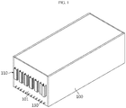
- FIG. 1 is a perspective view showing an appearance of a battery module according to an embodiment of the present disclosure
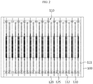
- FIG. 2 is a cross-sectioned view of FIG. 1 .
- a battery module includes a cell assembly 110 composed of a plurality of pouch cells 111, and a frame assembly having a bottom plate 120 into which the pouch cells 111 may be put and a side plate 100 disposed adjacent to an outermost side of the cell assembly 110.
- Each pouch cell 111 has a thin plate-like body, in which a positive electrode, a separator and a negative electrode are alternately stacked and an electrode tab is drawn out to at least one side.
- the positive electrode and the negative electrode are prepared by applying slurry containing an electrode active material, a binder resin, a conductive agent and other additives to at least one side of a current collector.
- the electrode active material may employ a general positive electrode active material such as a lithium-containing transition metal oxide
- the electrode active material may employ a general negative electrode active material such as a lithium metal, a carbon material, a metal compound, or mixtures thereof, which is capable of intercalating or de-intercalating lithium ions.
- As the separator a general porous polymer film used in a lithium secondary battery may be employed.
- the electrolyte accommodated in the pouch case together with the electrode assembly may employ a general electrolyte for a lithium secondary battery.
- the pouch case is made of sheet materials and has an accommodation portion for accommodating the electrode assembly.
- the pouch case is formed by combining a first case and a second case, which are formed by processing a sheet material into a predetermined shape.
- the sheet material of the pouch case may have a multi-layered structure in which an outer resin layer made provided at an outermost side and made of an insulating material such as polyethylene terephthalate (PET) and nylon, a metal layer made of aluminum capable of maintaining mechanical strength and preventing moisture and oxygen from penetrating, and an inner resin layer made of a polyolefin-based material having thermal adhesiveness to serve as a sealing material are laminated.
- an outer resin layer made provided at an outermost side and made of an insulating material such as polyethylene terephthalate (PET) and nylon
- PET polyethylene terephthalate
- metal layer made of aluminum capable of maintaining mechanical strength and preventing moisture and oxygen from penetrating
- an inner resin layer made of a polyolefin-based material having thermal adhesiveness to serve as a sealing material are laminated.
- the sheet material of the pouch case may include an adhesive resin layer between the inner resin layer and the metal layer and between the outer resin layer and the metal layer, if required.
- the adhesive resin layer is intended for smooth adhesion between different kinds of materials and is formed as a single layer or multi layers.
- the adhesive resin layer may be generally made of a polyolefin-based resin, or a polyurethane resin for smooth processing, or a mixture thereof.
- the edge portion 112 corresponds to a flange portion where sealing is performed by thermal compression for efficient bonding of the pouch case.
- the edge portion 112 of the pouch cell 111 has a relatively thin thickness compared to a body portion.
- the plurality of pouch cells 111 are arranged in one direction to substantially form a stacked structure.
- the frame assembly is a structure for accommodating the cell assembly 110 to support and protect the cell assembly 110, and includes a bottom plate 120 located at a lower portion of the cell assembly 110 and a side plate 100 disposed adjacent to an outermost side of the cell assembly 110.
- Each of the plates 100, 120 of the frame assembly is made by a thin metal plate with a small thickness, such as an aluminum plate.
- the bottom plate 120 has a base surface capable of collectively supporting bottom surfaces of the plurality of pouch cells 111. At the base surface of the bottom plate 120, slits are formed at predetermined intervals so that the edge portions 112 of the pouch cells 111 may be inserted therein in a one-to-one relationship with the pouch cells 111.
- the arrangement direction of the pouch cells 111 and the arrangement direction of the slits coincide with each other.
- empty spaces 125 are respectively formed between adjacent edge portions 112, and the empty spaces 125 are used as a cooling channel. That is, a cooling fluid such as an insulating oil is supplied into the empty space 125 and cooled from the edge portions of the pouch cells 111. As shown in FIG. 4 , the cooling fluid moves along the channel that is continuously formed from one end of the battery module to the other end thereof.
- the side plate 100 is made of a metal plate having a relatively small width and a great length and is disposed perpendicular to the plane of the bottom plate 120 and adjacent to the outermost side of the cell assembly 110.
- a pair of end plates 101 are disposed at both ends of the frame assembly in a length direction.
- the pair of end plates 101 are coupled to both sides of the bottom plate 120 and the upper plate in the length direction and to the side plate 100 to support both ends of the pouch cells 111.
- an end of a cooling hose 130 is disposed to be drawn outward.
- the cooling hose 130 is installed to communicate with the empty space 125 in a one-to-one relationship.
- the cooling hose 130 may also be arranged long so as to be longitudinally inserted into each empty space 125.
- an insert hole 131 is formed in the other one of the pair of end plates 101, as shown in FIG. 3 .
- the cooling hose 130 may be disposed inside the insert hole 131.
- different battery modules A, B may be used in a state of being connected to each other back and forth to form an assembly.
- the cooling hose 130 located at any one module is inserted into the insert hole 131 formed at another module and connected to the cooling hose 130 of the another module. If different modules are connected back and forth by using the cooling hose 130, there is no need for a separate pack plate for connecting and integrating the modules together.
- the battery module according to an embodiment of the present disclosure is assembled so that the frame assembly is combined in the unit of the plurality of pouch cells 111.
- the frame assembly includes the bottom plate 120 having slits formed therein and the side plate 100 disposed perpendicular to the bottom plate 120, and the plurality of pouch cells 111 are completely disposed by putting the edge portions 112 of the pouch cells 111 into the slits of the bottom plate 120, respectively, and then sealing the same.
- cooling is performed from the edge portions of the pouch cells 111.
- the space for a cooling channel may be secured by using the empty spaces naturally formed by disposing the pouch cells, it is possible to make a battery module having a simplified structure and a reduced process cost.
Landscapes
- Chemical & Material Sciences (AREA)
- Chemical Kinetics & Catalysis (AREA)
- Electrochemistry (AREA)
- General Chemical & Material Sciences (AREA)
- Engineering & Computer Science (AREA)
- Manufacturing & Machinery (AREA)
- Secondary Cells (AREA)
- Battery Mounting, Suspending (AREA)
Abstract
Description
- The present application claims priority to Korean Patent Application No.
10-2016-0124854 filed on September 28, 2016 - The present disclosure relates to a battery module, and more particularly, to a battery module having a cooling channel with an improved structure for allowing a cooling fluid to flow, and an assembling method and a frame assembly thereof.
- Generally, a battery module has a structure including a plurality of cells connected in series and/or in parallel. The battery module generally includes a cell assembly having a plurality of cells arranged and stacked in one direction, and a frame having plates capable of surrounding the cell assembly.
- In the conventional battery module, when a cooling channel is separately designed for cooling the battery cells, the space occupied by the cooling channel is separately required, so it is difficult to simplify the structure and there is limit in capacity of cells to be mounted.
- In relation to the technology for cooling the battery module, Korean Unexamined Patent Publication No.
2011-0130312 - Korean Patent Registration No.
10-0836398 - In addition, Korean Unexamined Patent Publication No.
2013-0105653 - Although the above technologies have been proposed, the battery module according to the conventional art has a limitation in securing a space for installing a cooling channel, and a process cost is increased by adding separate components for installing the cooling channel.
- The present disclosure is designed to solve the problems of the related art, and therefore the present disclosure is directed to providing a battery module capable of securing a space for a cooling channel by using a pouch cell built in a battery cell, and an assembling method and a frame assembly thereof.
- The present disclosure is also directed to providing a battery module capable of connecting to another battery module by using the cooling channel, and an assembling method and a frame assembly thereof.
- In one aspect of the present disclosure, there is provided a battery module, comprising: a cell assembly composed of pouch cells; a bottom plate configured to support the cell assembly and having slits formed therein at predetermined intervals so that edge portions of the pouch cells are put therein; and a side plate provided perpendicular to a plane of the bottom plate and disposed adjacent to an outermost side of the cell assembly, wherein as the edge portions of the pouch cells are put into the slits of the bottom plate, empty spaces are respectively formed between adjacent edge portions, and wherein the empty spaces are used as a cooling channel.
- In the present disclosure, the battery module may further comprise a cooling hose disposed to communicate with the empty space.
- In the present disclosure, the battery module may further include a pair of end plates disposed at both ends of the cell assembly, and at any one of the pair of end plates, an end of the cooling hose may be drawn outwards.
- In the present disclosure, the cooling hose located at any one battery module may be coupled to the cooling hose located at another battery module so that different modules are connected in series.
- In another aspect of the present disclosure, there is also provided a method for assembling a battery module, comprising: (a) preparing a frame assembly, which includes a bottom plate configured to supporting a cell assembly composed of pouch cells and having slits formed therein at predetermined intervals so that edge portions of the pouch cells are put therein, and a side plate provided perpendicular to a plane of the bottom plate and disposed adjacent to an outermost side of the cell assembly; (b) disposing the pouch cells by putting the edge portions of the pouch cells into the slits of the bottom plate; and (c) disposing a cooling hose communicating with empty spaces respectively formed between adjacent edge portions as the edge portions of the pouch cell are put into the slits.
- In another aspect of the present disclosure, there is also provided a frame assembly of a battery module, which supports a plurality of pouch cells at an outside of the battery module, the frame assembly comprising: a bottom plate configured to support the pouch cells and having slits formed therein at predetermined intervals so that edge portions of the pouch cells are put therein; and a side plate provided perpendicular to a plane of the bottom plate and disposed adjacent to an outermost side of the cell assembly, wherein as the edge portions of the pouch cells are put into the slits of the bottom plate, empty spaces serving as a cooling channel are respectively formed between adjacent edge portions.
- According to the present disclosure, since the space for a cooling channel may be secured between adjacent cells by using the edge structure of the pouch cell included in the battery module, the battery module may have a simplified structure and may be manufactured with lower cost.
- In addition, since different modules may be connected back and forth by using a cooling hose, a pack plate for connecting modules is not separately needed.
- The accompanying drawings illustrate a preferred embodiment of the present disclosure and together with the foregoing disclosure, serve to provide further understanding of the technical features of the present disclosure, and thus, the present disclosure is not construed as being limited to the drawing.
-
FIG. 1 is a perspective view showing an appearance of a battery module according to an embodiment of the present disclosure. -
FIG. 2 is a cross-sectioned view ofFIG. 1 . -
FIG. 3 is a rear view ofFIG. 1 . -
FIG. 4 is a side view ofFIG. 1 . -
FIG. 5 is a perspective view showing that different battery modules are connected in series. -
FIG. 6 is an exploded perspective view showing a coupled structure of a portion C inFIG. 5 . -
FIG. 1 is a perspective view showing an appearance of a battery module according to an embodiment of the present disclosure, andFIG. 2 is a cross-sectioned view ofFIG. 1 . - Referring to
FIGS. 1 and2 , a battery module according to an embodiment of the present disclosure includes acell assembly 110 composed of a plurality ofpouch cells 111, and a frame assembly having abottom plate 120 into which thepouch cells 111 may be put and aside plate 100 disposed adjacent to an outermost side of thecell assembly 110. - Each
pouch cell 111 has a thin plate-like body, in which a positive electrode, a separator and a negative electrode are alternately stacked and an electrode tab is drawn out to at least one side. The positive electrode and the negative electrode are prepared by applying slurry containing an electrode active material, a binder resin, a conductive agent and other additives to at least one side of a current collector. In case of the positive electrode, the electrode active material may employ a general positive electrode active material such as a lithium-containing transition metal oxide, and in the case of the negative electrode, the electrode active material may employ a general negative electrode active material such as a lithium metal, a carbon material, a metal compound, or mixtures thereof, which is capable of intercalating or de-intercalating lithium ions. As the separator, a general porous polymer film used in a lithium secondary battery may be employed. - The electrolyte accommodated in the pouch case together with the electrode assembly may employ a general electrolyte for a lithium secondary battery. The pouch case is made of sheet materials and has an accommodation portion for accommodating the electrode assembly. Preferably, the pouch case is formed by combining a first case and a second case, which are formed by processing a sheet material into a predetermined shape. The sheet material of the pouch case may have a multi-layered structure in which an outer resin layer made provided at an outermost side and made of an insulating material such as polyethylene terephthalate (PET) and nylon, a metal layer made of aluminum capable of maintaining mechanical strength and preventing moisture and oxygen from penetrating, and an inner resin layer made of a polyolefin-based material having thermal adhesiveness to serve as a sealing material are laminated.
- The sheet material of the pouch case may include an adhesive resin layer between the inner resin layer and the metal layer and between the outer resin layer and the metal layer, if required. The adhesive resin layer is intended for smooth adhesion between different kinds of materials and is formed as a single layer or multi layers. The adhesive resin layer may be generally made of a polyolefin-based resin, or a polyurethane resin for smooth processing, or a mixture thereof.
- In the
pouch cell 111, theedge portion 112 corresponds to a flange portion where sealing is performed by thermal compression for efficient bonding of the pouch case. Thus, theedge portion 112 of thepouch cell 111 has a relatively thin thickness compared to a body portion. - The plurality of
pouch cells 111 are arranged in one direction to substantially form a stacked structure. - The frame assembly is a structure for accommodating the
cell assembly 110 to support and protect thecell assembly 110, and includes abottom plate 120 located at a lower portion of thecell assembly 110 and aside plate 100 disposed adjacent to an outermost side of thecell assembly 110. Each of theplates - The
bottom plate 120 has a base surface capable of collectively supporting bottom surfaces of the plurality ofpouch cells 111. At the base surface of thebottom plate 120, slits are formed at predetermined intervals so that theedge portions 112 of thepouch cells 111 may be inserted therein in a one-to-one relationship with thepouch cells 111. Here, the arrangement direction of thepouch cells 111 and the arrangement direction of the slits coincide with each other. - As the
edge portions 112 of thepouch cells 111 are inserted into the slits of thebottom plate 120,empty spaces 125 are respectively formed betweenadjacent edge portions 112, and theempty spaces 125 are used as a cooling channel. That is, a cooling fluid such as an insulating oil is supplied into theempty space 125 and cooled from the edge portions of thepouch cells 111. As shown inFIG. 4 , the cooling fluid moves along the channel that is continuously formed from one end of the battery module to the other end thereof. - The
side plate 100 is made of a metal plate having a relatively small width and a great length and is disposed perpendicular to the plane of thebottom plate 120 and adjacent to the outermost side of thecell assembly 110. - A pair of
end plates 101 are disposed at both ends of the frame assembly in a length direction. The pair ofend plates 101 are coupled to both sides of thebottom plate 120 and the upper plate in the length direction and to theside plate 100 to support both ends of thepouch cells 111. - At any one end of the pair of
end plates 101, an end of acooling hose 130 is disposed to be drawn outward. Thecooling hose 130 is installed to communicate with theempty space 125 in a one-to-one relationship. According to a modified example of the present disclosure, thecooling hose 130 may also be arranged long so as to be longitudinally inserted into eachempty space 125. - In addition, an
insert hole 131 is formed in the other one of the pair ofend plates 101, as shown inFIG. 3 . Thecooling hose 130 may be disposed inside theinsert hole 131. - As shown in
FIG. 5 , different battery modules A, B may be used in a state of being connected to each other back and forth to form an assembly. At this time, at a coupling portion C as shown inFIG. 6 , the coolinghose 130 located at any one module is inserted into theinsert hole 131 formed at another module and connected to thecooling hose 130 of the another module. If different modules are connected back and forth by using thecooling hose 130, there is no need for a separate pack plate for connecting and integrating the modules together. - The battery module according to an embodiment of the present disclosure is assembled so that the frame assembly is combined in the unit of the plurality of
pouch cells 111. - The frame assembly includes the
bottom plate 120 having slits formed therein and theside plate 100 disposed perpendicular to thebottom plate 120, and the plurality ofpouch cells 111 are completely disposed by putting theedge portions 112 of thepouch cells 111 into the slits of thebottom plate 120, respectively, and then sealing the same. - As the
edge portions 112 of thepouch cell 111 are put into the slits of thebottom plate 120,empty spaces 125 are respectively formed between adjacent edge portions, and theempty spaces 125 are used as a cooling channel. - If a cooling fluid such as an insulation oil flows through the cooling
hose 130 after the assembling is completed, cooling is performed from the edge portions of thepouch cells 111. - If the present disclosure is applied, since the space for a cooling channel may be secured by using the empty spaces naturally formed by disposing the pouch cells, it is possible to make a battery module having a simplified structure and a reduced process cost.
Claims (9)
- A battery module, comprising:a cell assembly composed of pouch cells;a bottom plate configured to support the cell assembly and having slits formed therein at predetermined intervals so that edge portions of the pouch cells are put therein; anda side plate provided perpendicular to a plane of the bottom plate and disposed adjacent to an outermost side of the cell assembly,wherein as the edge portions of the pouch cells are put into the slits of the bottom plate, empty spaces are respectively formed between adjacent edge portions, andwherein the empty spaces are used as a cooling channel.
- The battery module according to claim 1, further comprising:
a cooling hose disposed to communicate with the empty space. - The battery module according to claim 2, further comprising:a pair of end plates disposed at both ends of the cell assembly,wherein at any one of the pair of end plates, an end of the cooling hose is drawn outwards.
- The battery module according to claim 1,
wherein the cooling hose located at any one battery module is coupled to the cooling hose located at another battery module so that different modules are connected in series. - A method for assembling a battery module, comprising:(a) preparing a frame assembly, which includes a bottom plate configured to supporting a cell assembly composed of pouch cells and having slits formed therein at predetermined intervals so that edge portions of the pouch cells are put therein, and a side plate provided perpendicular to a plane of the bottom plate and disposed adjacent to an outermost side of the cell assembly;(b) disposing the pouch cells by putting the edge portions of the pouch cells into the slits of the bottom plate; and(c) disposing a cooling hose communicating with empty spaces respectively formed between adjacent edge portions as the edge portions of the pouch cell are put into the slits.
- The method for assembling a battery module according to claim 5, after the step (a), further comprising:disposing a pair of end plates adjacent to both ends of the cell assembly,wherein at any one of the pair of end plates, an end of the cooling hose is drawn outwards.
- The method for assembling a battery module according to claim 6,
wherein the cooling hose located at any one battery module is coupled to the cooling hose located at another battery module so that different modules are connected in series. - A frame assembly of a battery module, which supports a plurality of pouch cells at an outside of the battery module, the frame assembly comprising:a bottom plate configured to support the pouch cells and having slits formed therein at predetermined intervals so that edge portions of the pouch cells are put therein; anda side plate provided perpendicular to a plane of the bottom plate and disposed adjacent to an outermost side of the cell assembly,wherein as the edge portions of the pouch cells are put into the slits of the bottom plate, empty spaces serving as a cooling channel are respectively formed between adjacent edge portions.
- The frame assembly according to claim 8, further comprising:a pair of end plates disposed at both ends of the cell assembly,wherein at any one of the pair of end plates, an end of a cooling hose capable of communicating with the empty spaces serving as a cooling channel is drawn outwards.
Applications Claiming Priority (2)
| Application Number | Priority Date | Filing Date | Title |
|---|---|---|---|
| KR1020160124854A KR102130818B1 (en) | 2016-09-28 | 2016-09-28 | Secondary battery module having cooling passage, fabrication method and frame assembly for the same |
| PCT/KR2017/010742 WO2018062863A1 (en) | 2016-09-28 | 2017-09-27 | Battery module having cooling flow path, method for assembling same, and frame assembly |
Publications (3)
| Publication Number | Publication Date |
|---|---|
| EP3382790A1 true EP3382790A1 (en) | 2018-10-03 |
| EP3382790A4 EP3382790A4 (en) | 2019-01-02 |
| EP3382790B1 EP3382790B1 (en) | 2020-11-04 |
Family
ID=61759766
Family Applications (1)
| Application Number | Title | Priority Date | Filing Date |
|---|---|---|---|
| EP17856749.1A Active EP3382790B1 (en) | 2016-09-28 | 2017-09-27 | Battery module having cooling channel, and assembling method and frame assembly thereof |
Country Status (7)
| Country | Link |
|---|---|
| US (1) | US10957949B2 (en) |
| EP (1) | EP3382790B1 (en) |
| JP (1) | JP7034411B2 (en) |
| KR (1) | KR102130818B1 (en) |
| CN (1) | CN108432034B (en) |
| PL (1) | PL3382790T3 (en) |
| WO (1) | WO2018062863A1 (en) |
Families Citing this family (9)
| Publication number | Priority date | Publication date | Assignee | Title |
|---|---|---|---|---|
| KR102372348B1 (en) | 2018-06-08 | 2022-03-07 | 주식회사 엘지에너지솔루션 | Battery module with improved cooling structure |
| KR20200115824A (en) * | 2019-03-27 | 2020-10-08 | 현대자동차주식회사 | Cooling system for battery of vehicle |
| KR102744712B1 (en) | 2019-10-08 | 2024-12-18 | 주식회사 엘지에너지솔루션 | Battery pack and vehicle comprising the same |
| KR102520590B1 (en) * | 2019-10-24 | 2023-04-10 | 주식회사 엘지에너지솔루션 | Battery module and battery pack including the same |
| KR102686222B1 (en) * | 2020-10-16 | 2024-07-17 | 주식회사 엘지에너지솔루션 | Battery pack and vehicle comprising the same |
| KR102856138B1 (en) * | 2020-11-16 | 2025-09-04 | 주식회사 엘지에너지솔루션 | Battery module having a cooling structure using insulating oil, and a battery pack and vehicle comprising the same |
| WO2022137112A1 (en) * | 2020-12-21 | 2022-06-30 | Phase Motion Control S.P.A. | Battery pack comprising flat cells |
| CN112864510B (en) * | 2021-04-23 | 2021-08-03 | 苏州清陶新能源科技有限公司 | A soft pack battery pack |
| KR20240042806A (en) | 2022-09-26 | 2024-04-02 | 에스케이온 주식회사 | Case for battery module and battery pack |
Family Cites Families (28)
| Publication number | Priority date | Publication date | Assignee | Title |
|---|---|---|---|---|
| JP4572019B2 (en) | 1999-10-08 | 2010-10-27 | パナソニック株式会社 | Assembled battery |
| KR100836398B1 (en) | 2006-12-12 | 2008-06-09 | 현대자동차주식회사 | Battery Module Cooling Support |
| US8409743B2 (en) | 2007-11-28 | 2013-04-02 | Sanyo Electric Co., Ltd. | Battery system with battery cells arranged in array alignment |
| KR101112442B1 (en) * | 2008-10-14 | 2012-02-20 | 주식회사 엘지화학 | Battery Module Assembly of Improved Cooling Efficiency |
| DE102009052254A1 (en) * | 2009-11-06 | 2011-05-12 | Behr Gmbh & Co. Kg | Power storage device |
| JP2011175743A (en) | 2010-02-23 | 2011-09-08 | Sanyo Electric Co Ltd | Power source apparatus, and vehicle equipped with the same |
| US8383260B2 (en) * | 2010-02-26 | 2013-02-26 | GM Global Technology Operations LLC | U-formed cooling plate with solid fins for lithium pouch cells |
| KR101263245B1 (en) | 2010-05-27 | 2013-05-10 | 한라비스테온공조 주식회사 | Battery cooling apparatus |
| US8492019B2 (en) * | 2010-08-17 | 2013-07-23 | GM Global Technology Operations LLC | Extruded thermal fin for temperature control of battery cells |
| JP5804323B2 (en) | 2011-01-07 | 2015-11-04 | 株式会社Gsユアサ | Power storage element and power storage device |
| JP6020942B2 (en) * | 2011-01-07 | 2016-11-02 | 株式会社Gsユアサ | Power storage device |
| CN102714283B (en) | 2011-01-24 | 2015-03-11 | 冯国安 | Power battery pack cooling device |
| DE102011102765A1 (en) * | 2011-05-28 | 2012-11-29 | Audi Ag | Battery for a vehicle and method of manufacturing a battery |
| KR101261736B1 (en) * | 2011-06-13 | 2013-05-07 | 로베르트 보쉬 게엠베하 | Battery Pack |
| JP2013012441A (en) | 2011-06-30 | 2013-01-17 | Sanyo Electric Co Ltd | Electric power source device and vehicle including the same |
| US20140220391A1 (en) | 2011-08-26 | 2014-08-07 | Sanyo Electric Co., Ltd., | Power source apparatus, and vehicle and power storage device equipped with that power source apparatus |
| US9761850B2 (en) * | 2011-10-28 | 2017-09-12 | Nucleus Scientific, Inc. | Multi-cell battery assembly |
| DE102011086246A1 (en) | 2011-11-14 | 2013-05-16 | Sb Limotive Company Ltd. | Battery system and motor vehicle |
| KR101447057B1 (en) * | 2012-01-26 | 2014-10-07 | 주식회사 엘지화학 | Battery Module Having Heat Dissipation Mounting Member for Dissipating Heat And Mounting Battery cell |
| JP2012227164A (en) * | 2012-07-20 | 2012-11-15 | Sanyo Electric Co Ltd | Battery system |
| KR101527352B1 (en) * | 2012-09-07 | 2015-06-10 | 주식회사 엘지화학 | Battery Module Having Pulse-type Pin |
| US20140295235A1 (en) * | 2013-03-29 | 2014-10-02 | Samsung Sdi Co., Ltd. | Battery module |
| KR20140140795A (en) * | 2013-05-30 | 2014-12-10 | 삼성에스디아이 주식회사 | Battery module |
| JP6174388B2 (en) * | 2013-06-19 | 2017-08-02 | 日立オートモティブシステムズ株式会社 | Battery module |
| KR101608853B1 (en) * | 2013-06-20 | 2016-04-04 | 주식회사 엘지화학 | Frame for secondary battery and battery module including the same |
| KR101743697B1 (en) | 2014-04-14 | 2017-06-20 | 주식회사 엘지화학 | Battery module having separated cooling path and venting path and battery pack including the same |
| WO2016063434A1 (en) * | 2014-10-21 | 2016-04-28 | 三洋電機株式会社 | Power supply device |
| KR102327156B1 (en) * | 2014-12-30 | 2021-11-16 | 에이치엘그린파워 주식회사 | Battery pack for preventing gas leak |
-
2016
- 2016-09-28 KR KR1020160124854A patent/KR102130818B1/en active Active
-
2017
- 2017-09-27 EP EP17856749.1A patent/EP3382790B1/en active Active
- 2017-09-27 US US15/781,569 patent/US10957949B2/en active Active
- 2017-09-27 WO PCT/KR2017/010742 patent/WO2018062863A1/en not_active Ceased
- 2017-09-27 CN CN201780005336.9A patent/CN108432034B/en active Active
- 2017-09-27 PL PL17856749.1T patent/PL3382790T3/en unknown
- 2017-09-27 JP JP2018538608A patent/JP7034411B2/en active Active
Also Published As
| Publication number | Publication date |
|---|---|
| US20190334217A1 (en) | 2019-10-31 |
| WO2018062863A1 (en) | 2018-04-05 |
| PL3382790T3 (en) | 2021-02-22 |
| KR102130818B1 (en) | 2020-07-06 |
| US10957949B2 (en) | 2021-03-23 |
| CN108432034A (en) | 2018-08-21 |
| KR20180034958A (en) | 2018-04-05 |
| EP3382790B1 (en) | 2020-11-04 |
| JP2019507469A (en) | 2019-03-14 |
| CN108432034B (en) | 2021-02-02 |
| EP3382790A4 (en) | 2019-01-02 |
| JP7034411B2 (en) | 2022-03-14 |
Similar Documents
| Publication | Publication Date | Title |
|---|---|---|
| EP3382790B1 (en) | Battery module having cooling channel, and assembling method and frame assembly thereof | |
| US10601091B2 (en) | Rechargeable battery module | |
| EP3373384B1 (en) | Battery module | |
| EP3671946B1 (en) | Battery module having improved cooling structure | |
| KR102073853B1 (en) | Secondary battery module improved in cooling passage and frame assembly for the same | |
| JP6713547B2 (en) | Multi-cavity battery module | |
| EP3392957B1 (en) | Air-cooling battery module | |
| CN106486634A (en) | Battery module | |
| EP3211688B1 (en) | Rechargeable battery | |
| KR20180035174A (en) | Secondary battery module improved in frame structure and frame assembly for the same | |
| US11114712B2 (en) | Battery module having improved cooling structure | |
| US20230343983A1 (en) | Apparatus for Manufacturing Pouch Type Battery | |
| US10637033B2 (en) | Battery pack having improved cell lead fixing structure | |
| EP3312928B1 (en) | Lithium ion secondary battery | |
| KR102196103B1 (en) | Method of manufacturing electrode assembly, electrode assembly thereof and lithium secondary battery comprising the same | |
| US12263759B2 (en) | Temperature control apparatus | |
| KR20210011590A (en) | Method of manufacturing electrode assembly, electrode assembly thereof and lithium secondary battery comprising the same | |
| KR20240042806A (en) | Case for battery module and battery pack | |
| KR102196102B1 (en) | Electrode assembly comprising bicells and lithium secondary battery comprising the same | |
| KR102274052B1 (en) | Method of manufacturing pocketed electrode plate | |
| EP4611127A1 (en) | Battery pack and method for manufacturing same | |
| KR102885751B1 (en) | Battery Cell Cartridge with Cooling Pin, Battery Module including Battery Cell Cartridge and Manufacturing Method Thereof | |
| KR20220127902A (en) | Batteries, battery modules, battery packs, and electric vehicles |
Legal Events
| Date | Code | Title | Description |
|---|---|---|---|
| STAA | Information on the status of an ep patent application or granted ep patent |
Free format text: STATUS: THE INTERNATIONAL PUBLICATION HAS BEEN MADE |
|
| PUAI | Public reference made under article 153(3) epc to a published international application that has entered the european phase |
Free format text: ORIGINAL CODE: 0009012 |
|
| STAA | Information on the status of an ep patent application or granted ep patent |
Free format text: STATUS: REQUEST FOR EXAMINATION WAS MADE |
|
| 17P | Request for examination filed |
Effective date: 20180626 |
|
| AK | Designated contracting states |
Kind code of ref document: A1 Designated state(s): AL AT BE BG CH CY CZ DE DK EE ES FI FR GB GR HR HU IE IS IT LI LT LU LV MC MK MT NL NO PL PT RO RS SE SI SK SM TR |
|
| AX | Request for extension of the european patent |
Extension state: BA ME |
|
| A4 | Supplementary search report drawn up and despatched |
Effective date: 20181204 |
|
| RIC1 | Information provided on ipc code assigned before grant |
Ipc: H01M 2/10 20060101ALI20181128BHEP Ipc: H01M 10/613 20140101ALI20181128BHEP Ipc: H01M 10/6556 20140101AFI20181128BHEP Ipc: H01M 2/02 20060101ALI20181128BHEP Ipc: H01M 10/6557 20140101ALI20181128BHEP |
|
| DAV | Request for validation of the european patent (deleted) | ||
| DAX | Request for extension of the european patent (deleted) | ||
| RIC1 | Information provided on ipc code assigned before grant |
Ipc: H01M 10/613 20140101ALI20200306BHEP Ipc: H01M 2/02 20060101ALI20200306BHEP Ipc: H01M 10/6557 20140101ALI20200306BHEP Ipc: H01M 2/10 20060101ALI20200306BHEP Ipc: H01M 10/6556 20140101AFI20200306BHEP |
|
| GRAP | Despatch of communication of intention to grant a patent |
Free format text: ORIGINAL CODE: EPIDOSNIGR1 |
|
| STAA | Information on the status of an ep patent application or granted ep patent |
Free format text: STATUS: GRANT OF PATENT IS INTENDED |
|
| INTG | Intention to grant announced |
Effective date: 20200603 |
|
| GRAS | Grant fee paid |
Free format text: ORIGINAL CODE: EPIDOSNIGR3 |
|
| GRAA | (expected) grant |
Free format text: ORIGINAL CODE: 0009210 |
|
| STAA | Information on the status of an ep patent application or granted ep patent |
Free format text: STATUS: THE PATENT HAS BEEN GRANTED |
|
| AK | Designated contracting states |
Kind code of ref document: B1 Designated state(s): AL AT BE BG CH CY CZ DE DK EE ES FI FR GB GR HR HU IE IS IT LI LT LU LV MC MK MT NL NO PL PT RO RS SE SI SK SM TR |
|
| REG | Reference to a national code |
Ref country code: GB Ref legal event code: FG4D |
|
| REG | Reference to a national code |
Ref country code: CH Ref legal event code: EP |
|
| REG | Reference to a national code |
Ref country code: AT Ref legal event code: REF Ref document number: 1332015 Country of ref document: AT Kind code of ref document: T Effective date: 20201115 |
|
| REG | Reference to a national code |
Ref country code: IE Ref legal event code: FG4D |
|
| REG | Reference to a national code |
Ref country code: DE Ref legal event code: R096 Ref document number: 602017027144 Country of ref document: DE |
|
| REG | Reference to a national code |
Ref country code: SE Ref legal event code: TRGR |
|
| REG | Reference to a national code |
Ref country code: NL Ref legal event code: MP Effective date: 20201104 |
|
| REG | Reference to a national code |
Ref country code: AT Ref legal event code: MK05 Ref document number: 1332015 Country of ref document: AT Kind code of ref document: T Effective date: 20201104 |
|
| PG25 | Lapsed in a contracting state [announced via postgrant information from national office to epo] |
Ref country code: GR Free format text: LAPSE BECAUSE OF FAILURE TO SUBMIT A TRANSLATION OF THE DESCRIPTION OR TO PAY THE FEE WITHIN THE PRESCRIBED TIME-LIMIT Effective date: 20210205 Ref country code: NO Free format text: LAPSE BECAUSE OF FAILURE TO SUBMIT A TRANSLATION OF THE DESCRIPTION OR TO PAY THE FEE WITHIN THE PRESCRIBED TIME-LIMIT Effective date: 20210204 Ref country code: FI Free format text: LAPSE BECAUSE OF FAILURE TO SUBMIT A TRANSLATION OF THE DESCRIPTION OR TO PAY THE FEE WITHIN THE PRESCRIBED TIME-LIMIT Effective date: 20201104 Ref country code: RS Free format text: LAPSE BECAUSE OF FAILURE TO SUBMIT A TRANSLATION OF THE DESCRIPTION OR TO PAY THE FEE WITHIN THE PRESCRIBED TIME-LIMIT Effective date: 20201104 Ref country code: PT Free format text: LAPSE BECAUSE OF FAILURE TO SUBMIT A TRANSLATION OF THE DESCRIPTION OR TO PAY THE FEE WITHIN THE PRESCRIBED TIME-LIMIT Effective date: 20210304 |
|
| PG25 | Lapsed in a contracting state [announced via postgrant information from national office to epo] |
Ref country code: AT Free format text: LAPSE BECAUSE OF FAILURE TO SUBMIT A TRANSLATION OF THE DESCRIPTION OR TO PAY THE FEE WITHIN THE PRESCRIBED TIME-LIMIT Effective date: 20201104 Ref country code: ES Free format text: LAPSE BECAUSE OF FAILURE TO SUBMIT A TRANSLATION OF THE DESCRIPTION OR TO PAY THE FEE WITHIN THE PRESCRIBED TIME-LIMIT Effective date: 20201104 Ref country code: BG Free format text: LAPSE BECAUSE OF FAILURE TO SUBMIT A TRANSLATION OF THE DESCRIPTION OR TO PAY THE FEE WITHIN THE PRESCRIBED TIME-LIMIT Effective date: 20210204 Ref country code: IS Free format text: LAPSE BECAUSE OF FAILURE TO SUBMIT A TRANSLATION OF THE DESCRIPTION OR TO PAY THE FEE WITHIN THE PRESCRIBED TIME-LIMIT Effective date: 20210304 Ref country code: LV Free format text: LAPSE BECAUSE OF FAILURE TO SUBMIT A TRANSLATION OF THE DESCRIPTION OR TO PAY THE FEE WITHIN THE PRESCRIBED TIME-LIMIT Effective date: 20201104 |
|
| REG | Reference to a national code |
Ref country code: LT Ref legal event code: MG9D |
|
| PG25 | Lapsed in a contracting state [announced via postgrant information from national office to epo] |
Ref country code: HR Free format text: LAPSE BECAUSE OF FAILURE TO SUBMIT A TRANSLATION OF THE DESCRIPTION OR TO PAY THE FEE WITHIN THE PRESCRIBED TIME-LIMIT Effective date: 20201104 |
|
| PG25 | Lapsed in a contracting state [announced via postgrant information from national office to epo] |
Ref country code: LT Free format text: LAPSE BECAUSE OF FAILURE TO SUBMIT A TRANSLATION OF THE DESCRIPTION OR TO PAY THE FEE WITHIN THE PRESCRIBED TIME-LIMIT Effective date: 20201104 Ref country code: EE Free format text: LAPSE BECAUSE OF FAILURE TO SUBMIT A TRANSLATION OF THE DESCRIPTION OR TO PAY THE FEE WITHIN THE PRESCRIBED TIME-LIMIT Effective date: 20201104 Ref country code: CZ Free format text: LAPSE BECAUSE OF FAILURE TO SUBMIT A TRANSLATION OF THE DESCRIPTION OR TO PAY THE FEE WITHIN THE PRESCRIBED TIME-LIMIT Effective date: 20201104 Ref country code: SM Free format text: LAPSE BECAUSE OF FAILURE TO SUBMIT A TRANSLATION OF THE DESCRIPTION OR TO PAY THE FEE WITHIN THE PRESCRIBED TIME-LIMIT Effective date: 20201104 Ref country code: RO Free format text: LAPSE BECAUSE OF FAILURE TO SUBMIT A TRANSLATION OF THE DESCRIPTION OR TO PAY THE FEE WITHIN THE PRESCRIBED TIME-LIMIT Effective date: 20201104 Ref country code: SK Free format text: LAPSE BECAUSE OF FAILURE TO SUBMIT A TRANSLATION OF THE DESCRIPTION OR TO PAY THE FEE WITHIN THE PRESCRIBED TIME-LIMIT Effective date: 20201104 |
|
| REG | Reference to a national code |
Ref country code: DE Ref legal event code: R097 Ref document number: 602017027144 Country of ref document: DE |
|
| PG25 | Lapsed in a contracting state [announced via postgrant information from national office to epo] |
Ref country code: DK Free format text: LAPSE BECAUSE OF FAILURE TO SUBMIT A TRANSLATION OF THE DESCRIPTION OR TO PAY THE FEE WITHIN THE PRESCRIBED TIME-LIMIT Effective date: 20201104 |
|
| PLBE | No opposition filed within time limit |
Free format text: ORIGINAL CODE: 0009261 |
|
| STAA | Information on the status of an ep patent application or granted ep patent |
Free format text: STATUS: NO OPPOSITION FILED WITHIN TIME LIMIT |
|
| 26N | No opposition filed |
Effective date: 20210805 |
|
| PG25 | Lapsed in a contracting state [announced via postgrant information from national office to epo] |
Ref country code: AL Free format text: LAPSE BECAUSE OF FAILURE TO SUBMIT A TRANSLATION OF THE DESCRIPTION OR TO PAY THE FEE WITHIN THE PRESCRIBED TIME-LIMIT Effective date: 20201104 Ref country code: NL Free format text: LAPSE BECAUSE OF FAILURE TO SUBMIT A TRANSLATION OF THE DESCRIPTION OR TO PAY THE FEE WITHIN THE PRESCRIBED TIME-LIMIT Effective date: 20201104 Ref country code: IT Free format text: LAPSE BECAUSE OF FAILURE TO SUBMIT A TRANSLATION OF THE DESCRIPTION OR TO PAY THE FEE WITHIN THE PRESCRIBED TIME-LIMIT Effective date: 20201104 |
|
| PG25 | Lapsed in a contracting state [announced via postgrant information from national office to epo] |
Ref country code: SI Free format text: LAPSE BECAUSE OF FAILURE TO SUBMIT A TRANSLATION OF THE DESCRIPTION OR TO PAY THE FEE WITHIN THE PRESCRIBED TIME-LIMIT Effective date: 20201104 |
|
| REG | Reference to a national code |
Ref country code: CH Ref legal event code: PL |
|
| REG | Reference to a national code |
Ref country code: BE Ref legal event code: MM Effective date: 20210930 |
|
| PG25 | Lapsed in a contracting state [announced via postgrant information from national office to epo] |
Ref country code: IS Free format text: LAPSE BECAUSE OF FAILURE TO SUBMIT A TRANSLATION OF THE DESCRIPTION OR TO PAY THE FEE WITHIN THE PRESCRIBED TIME-LIMIT Effective date: 20210304 Ref country code: MC Free format text: LAPSE BECAUSE OF FAILURE TO SUBMIT A TRANSLATION OF THE DESCRIPTION OR TO PAY THE FEE WITHIN THE PRESCRIBED TIME-LIMIT Effective date: 20201104 |
|
| PG25 | Lapsed in a contracting state [announced via postgrant information from national office to epo] |
Ref country code: LU Free format text: LAPSE BECAUSE OF NON-PAYMENT OF DUE FEES Effective date: 20210927 Ref country code: IE Free format text: LAPSE BECAUSE OF NON-PAYMENT OF DUE FEES Effective date: 20210927 Ref country code: BE Free format text: LAPSE BECAUSE OF NON-PAYMENT OF DUE FEES Effective date: 20210930 |
|
| PG25 | Lapsed in a contracting state [announced via postgrant information from national office to epo] |
Ref country code: LI Free format text: LAPSE BECAUSE OF NON-PAYMENT OF DUE FEES Effective date: 20210930 Ref country code: CH Free format text: LAPSE BECAUSE OF NON-PAYMENT OF DUE FEES Effective date: 20210930 |
|
| REG | Reference to a national code |
Ref country code: DE Ref legal event code: R081 Ref document number: 602017027144 Country of ref document: DE Owner name: LG ENERGY SOLUTION, LTD., KR Free format text: FORMER OWNER: LG CHEM, LTD., SEOUL, KR |
|
| P01 | Opt-out of the competence of the unified patent court (upc) registered |
Effective date: 20230512 |
|
| PG25 | Lapsed in a contracting state [announced via postgrant information from national office to epo] |
Ref country code: CY Free format text: LAPSE BECAUSE OF FAILURE TO SUBMIT A TRANSLATION OF THE DESCRIPTION OR TO PAY THE FEE WITHIN THE PRESCRIBED TIME-LIMIT Effective date: 20201104 |
|
| PG25 | Lapsed in a contracting state [announced via postgrant information from national office to epo] |
Ref country code: HU Free format text: LAPSE BECAUSE OF FAILURE TO SUBMIT A TRANSLATION OF THE DESCRIPTION OR TO PAY THE FEE WITHIN THE PRESCRIBED TIME-LIMIT; INVALID AB INITIO Effective date: 20170927 |
|
| REG | Reference to a national code |
Ref country code: GB Ref legal event code: 732E Free format text: REGISTERED BETWEEN 20230824 AND 20230831 |
|
| PG25 | Lapsed in a contracting state [announced via postgrant information from national office to epo] |
Ref country code: MK Free format text: LAPSE BECAUSE OF FAILURE TO SUBMIT A TRANSLATION OF THE DESCRIPTION OR TO PAY THE FEE WITHIN THE PRESCRIBED TIME-LIMIT Effective date: 20201104 |
|
| PG25 | Lapsed in a contracting state [announced via postgrant information from national office to epo] |
Ref country code: MT Free format text: LAPSE BECAUSE OF FAILURE TO SUBMIT A TRANSLATION OF THE DESCRIPTION OR TO PAY THE FEE WITHIN THE PRESCRIBED TIME-LIMIT Effective date: 20201104 |
|
| PGFP | Annual fee paid to national office [announced via postgrant information from national office to epo] |
Ref country code: DE Payment date: 20250820 Year of fee payment: 9 |
|
| PGFP | Annual fee paid to national office [announced via postgrant information from national office to epo] |
Ref country code: PL Payment date: 20250822 Year of fee payment: 9 |
|
| PGFP | Annual fee paid to national office [announced via postgrant information from national office to epo] |
Ref country code: GB Payment date: 20250820 Year of fee payment: 9 |
|
| PGFP | Annual fee paid to national office [announced via postgrant information from national office to epo] |
Ref country code: FR Payment date: 20250821 Year of fee payment: 9 |
|
| PGFP | Annual fee paid to national office [announced via postgrant information from national office to epo] |
Ref country code: SE Payment date: 20250821 Year of fee payment: 9 |
|
| PG25 | Lapsed in a contracting state [announced via postgrant information from national office to epo] |
Ref country code: TR Free format text: LAPSE BECAUSE OF FAILURE TO SUBMIT A TRANSLATION OF THE DESCRIPTION OR TO PAY THE FEE WITHIN THE PRESCRIBED TIME-LIMIT Effective date: 20201104 |