EP3382784A1 - Fuel cell unit comprising casing incorporating fuel cell stack and electrical component - Google Patents
Fuel cell unit comprising casing incorporating fuel cell stack and electrical component Download PDFInfo
- Publication number
- EP3382784A1 EP3382784A1 EP18163975.8A EP18163975A EP3382784A1 EP 3382784 A1 EP3382784 A1 EP 3382784A1 EP 18163975 A EP18163975 A EP 18163975A EP 3382784 A1 EP3382784 A1 EP 3382784A1
- Authority
- EP
- European Patent Office
- Prior art keywords
- fuel cell
- cell stack
- case
- flow passage
- electrical component
- Prior art date
- Legal status (The legal status is an assumption and is not a legal conclusion. Google has not performed a legal analysis and makes no representation as to the accuracy of the status listed.)
- Granted
Links
- 239000000446 fuel Substances 0.000 title claims abstract description 125
- 238000005192 partition Methods 0.000 claims abstract description 5
- 239000002826 coolant Substances 0.000 claims description 38
- 230000008859 change Effects 0.000 claims description 4
- 239000011347 resin Substances 0.000 description 9
- 229920005989 resin Polymers 0.000 description 9
- 239000007788 liquid Substances 0.000 description 5
- 238000000034 method Methods 0.000 description 5
- 230000002457 bidirectional effect Effects 0.000 description 4
- 239000003990 capacitor Substances 0.000 description 3
- 238000009499 grossing Methods 0.000 description 3
- 239000000463 material Substances 0.000 description 3
- 238000010586 diagram Methods 0.000 description 2
- 238000009434 installation Methods 0.000 description 2
- 230000004044 response Effects 0.000 description 2
- XLYOFNOQVPJJNP-UHFFFAOYSA-N water Substances O XLYOFNOQVPJJNP-UHFFFAOYSA-N 0.000 description 2
- XAGFODPZIPBFFR-UHFFFAOYSA-N aluminium Chemical compound [Al] XAGFODPZIPBFFR-UHFFFAOYSA-N 0.000 description 1
- 229910052782 aluminium Inorganic materials 0.000 description 1
- 238000001816 cooling Methods 0.000 description 1
- 238000004512 die casting Methods 0.000 description 1
- 230000002708 enhancing effect Effects 0.000 description 1
- 238000012986 modification Methods 0.000 description 1
- 230000004048 modification Effects 0.000 description 1
- 230000010349 pulsation Effects 0.000 description 1
Images


Classifications
-
- H—ELECTRICITY
- H01—ELECTRIC ELEMENTS
- H01M—PROCESSES OR MEANS, e.g. BATTERIES, FOR THE DIRECT CONVERSION OF CHEMICAL ENERGY INTO ELECTRICAL ENERGY
- H01M8/00—Fuel cells; Manufacture thereof
- H01M8/24—Grouping of fuel cells, e.g. stacking of fuel cells
- H01M8/2465—Details of groupings of fuel cells
- H01M8/247—Arrangements for tightening a stack, for accommodation of a stack in a tank or for assembling different tanks
- H01M8/2475—Enclosures, casings or containers of fuel cell stacks
-
- B—PERFORMING OPERATIONS; TRANSPORTING
- B60—VEHICLES IN GENERAL
- B60L—PROPULSION OF ELECTRICALLY-PROPELLED VEHICLES; SUPPLYING ELECTRIC POWER FOR AUXILIARY EQUIPMENT OF ELECTRICALLY-PROPELLED VEHICLES; ELECTRODYNAMIC BRAKE SYSTEMS FOR VEHICLES IN GENERAL; MAGNETIC SUSPENSION OR LEVITATION FOR VEHICLES; MONITORING OPERATING VARIABLES OF ELECTRICALLY-PROPELLED VEHICLES; ELECTRIC SAFETY DEVICES FOR ELECTRICALLY-PROPELLED VEHICLES
- B60L50/00—Electric propulsion with power supplied within the vehicle
- B60L50/50—Electric propulsion with power supplied within the vehicle using propulsion power supplied by batteries or fuel cells
- B60L50/70—Electric propulsion with power supplied within the vehicle using propulsion power supplied by batteries or fuel cells using power supplied by fuel cells
- B60L50/71—Arrangement of fuel cells within vehicles specially adapted for electric vehicles
-
- B—PERFORMING OPERATIONS; TRANSPORTING
- B60—VEHICLES IN GENERAL
- B60L—PROPULSION OF ELECTRICALLY-PROPELLED VEHICLES; SUPPLYING ELECTRIC POWER FOR AUXILIARY EQUIPMENT OF ELECTRICALLY-PROPELLED VEHICLES; ELECTRODYNAMIC BRAKE SYSTEMS FOR VEHICLES IN GENERAL; MAGNETIC SUSPENSION OR LEVITATION FOR VEHICLES; MONITORING OPERATING VARIABLES OF ELECTRICALLY-PROPELLED VEHICLES; ELECTRIC SAFETY DEVICES FOR ELECTRICALLY-PROPELLED VEHICLES
- B60L3/00—Electric devices on electrically-propelled vehicles for safety purposes; Monitoring operating variables, e.g. speed, deceleration or energy consumption
- B60L3/0007—Measures or means for preventing or attenuating collisions
-
- B—PERFORMING OPERATIONS; TRANSPORTING
- B60—VEHICLES IN GENERAL
- B60L—PROPULSION OF ELECTRICALLY-PROPELLED VEHICLES; SUPPLYING ELECTRIC POWER FOR AUXILIARY EQUIPMENT OF ELECTRICALLY-PROPELLED VEHICLES; ELECTRODYNAMIC BRAKE SYSTEMS FOR VEHICLES IN GENERAL; MAGNETIC SUSPENSION OR LEVITATION FOR VEHICLES; MONITORING OPERATING VARIABLES OF ELECTRICALLY-PROPELLED VEHICLES; ELECTRIC SAFETY DEVICES FOR ELECTRICALLY-PROPELLED VEHICLES
- B60L50/00—Electric propulsion with power supplied within the vehicle
- B60L50/50—Electric propulsion with power supplied within the vehicle using propulsion power supplied by batteries or fuel cells
- B60L50/70—Electric propulsion with power supplied within the vehicle using propulsion power supplied by batteries or fuel cells using power supplied by fuel cells
- B60L50/72—Constructional details of fuel cells specially adapted for electric vehicles
-
- B—PERFORMING OPERATIONS; TRANSPORTING
- B60—VEHICLES IN GENERAL
- B60L—PROPULSION OF ELECTRICALLY-PROPELLED VEHICLES; SUPPLYING ELECTRIC POWER FOR AUXILIARY EQUIPMENT OF ELECTRICALLY-PROPELLED VEHICLES; ELECTRODYNAMIC BRAKE SYSTEMS FOR VEHICLES IN GENERAL; MAGNETIC SUSPENSION OR LEVITATION FOR VEHICLES; MONITORING OPERATING VARIABLES OF ELECTRICALLY-PROPELLED VEHICLES; ELECTRIC SAFETY DEVICES FOR ELECTRICALLY-PROPELLED VEHICLES
- B60L58/00—Methods or circuit arrangements for monitoring or controlling batteries or fuel cells, specially adapted for electric vehicles
- B60L58/40—Methods or circuit arrangements for monitoring or controlling batteries or fuel cells, specially adapted for electric vehicles for controlling a combination of batteries and fuel cells
-
- H—ELECTRICITY
- H01—ELECTRIC ELEMENTS
- H01F—MAGNETS; INDUCTANCES; TRANSFORMERS; SELECTION OF MATERIALS FOR THEIR MAGNETIC PROPERTIES
- H01F27/00—Details of transformers or inductances, in general
- H01F27/02—Casings
- H01F27/025—Constructional details relating to cooling
-
- H—ELECTRICITY
- H01—ELECTRIC ELEMENTS
- H01F—MAGNETS; INDUCTANCES; TRANSFORMERS; SELECTION OF MATERIALS FOR THEIR MAGNETIC PROPERTIES
- H01F27/00—Details of transformers or inductances, in general
- H01F27/08—Cooling; Ventilating
- H01F27/10—Liquid cooling
-
- H—ELECTRICITY
- H01—ELECTRIC ELEMENTS
- H01F—MAGNETS; INDUCTANCES; TRANSFORMERS; SELECTION OF MATERIALS FOR THEIR MAGNETIC PROPERTIES
- H01F37/00—Fixed inductances not covered by group H01F17/00
-
- H—ELECTRICITY
- H01—ELECTRIC ELEMENTS
- H01M—PROCESSES OR MEANS, e.g. BATTERIES, FOR THE DIRECT CONVERSION OF CHEMICAL ENERGY INTO ELECTRICAL ENERGY
- H01M8/00—Fuel cells; Manufacture thereof
- H01M8/02—Details
- H01M8/0202—Collectors; Separators, e.g. bipolar separators; Interconnectors
- H01M8/0267—Collectors; Separators, e.g. bipolar separators; Interconnectors having heating or cooling means, e.g. heaters or coolant flow channels
-
- H—ELECTRICITY
- H01—ELECTRIC ELEMENTS
- H01M—PROCESSES OR MEANS, e.g. BATTERIES, FOR THE DIRECT CONVERSION OF CHEMICAL ENERGY INTO ELECTRICAL ENERGY
- H01M8/00—Fuel cells; Manufacture thereof
- H01M8/04—Auxiliary arrangements, e.g. for control of pressure or for circulation of fluids
- H01M8/04007—Auxiliary arrangements, e.g. for control of pressure or for circulation of fluids related to heat exchange
- H01M8/04067—Heat exchange or temperature measuring elements, thermal insulation, e.g. heat pipes, heat pumps, fins
- H01M8/04074—Heat exchange unit structures specially adapted for fuel cell
-
- H—ELECTRICITY
- H01—ELECTRIC ELEMENTS
- H01M—PROCESSES OR MEANS, e.g. BATTERIES, FOR THE DIRECT CONVERSION OF CHEMICAL ENERGY INTO ELECTRICAL ENERGY
- H01M8/00—Fuel cells; Manufacture thereof
- H01M8/04—Auxiliary arrangements, e.g. for control of pressure or for circulation of fluids
- H01M8/04298—Processes for controlling fuel cells or fuel cell systems
- H01M8/04313—Processes for controlling fuel cells or fuel cell systems characterised by the detection or assessment of variables; characterised by the detection or assessment of failure or abnormal function
- H01M8/04537—Electric variables
- H01M8/04604—Power, energy, capacity or load
- H01M8/04619—Power, energy, capacity or load of fuel cell stacks
-
- H—ELECTRICITY
- H01—ELECTRIC ELEMENTS
- H01M—PROCESSES OR MEANS, e.g. BATTERIES, FOR THE DIRECT CONVERSION OF CHEMICAL ENERGY INTO ELECTRICAL ENERGY
- H01M8/00—Fuel cells; Manufacture thereof
- H01M8/24—Grouping of fuel cells, e.g. stacking of fuel cells
- H01M8/2465—Details of groupings of fuel cells
- H01M8/247—Arrangements for tightening a stack, for accommodation of a stack in a tank or for assembling different tanks
- H01M8/248—Means for compression of the fuel cell stacks
-
- H—ELECTRICITY
- H02—GENERATION; CONVERSION OR DISTRIBUTION OF ELECTRIC POWER
- H02M—APPARATUS FOR CONVERSION BETWEEN AC AND AC, BETWEEN AC AND DC, OR BETWEEN DC AND DC, AND FOR USE WITH MAINS OR SIMILAR POWER SUPPLY SYSTEMS; CONVERSION OF DC OR AC INPUT POWER INTO SURGE OUTPUT POWER; CONTROL OR REGULATION THEREOF
- H02M3/00—Conversion of dc power input into dc power output
- H02M3/02—Conversion of dc power input into dc power output without intermediate conversion into ac
- H02M3/04—Conversion of dc power input into dc power output without intermediate conversion into ac by static converters
- H02M3/10—Conversion of dc power input into dc power output without intermediate conversion into ac by static converters using discharge tubes with control electrode or semiconductor devices with control electrode
- H02M3/145—Conversion of dc power input into dc power output without intermediate conversion into ac by static converters using discharge tubes with control electrode or semiconductor devices with control electrode using devices of a triode or transistor type requiring continuous application of a control signal
- H02M3/155—Conversion of dc power input into dc power output without intermediate conversion into ac by static converters using discharge tubes with control electrode or semiconductor devices with control electrode using devices of a triode or transistor type requiring continuous application of a control signal using semiconductor devices only
- H02M3/156—Conversion of dc power input into dc power output without intermediate conversion into ac by static converters using discharge tubes with control electrode or semiconductor devices with control electrode using devices of a triode or transistor type requiring continuous application of a control signal using semiconductor devices only with automatic control of output voltage or current, e.g. switching regulators
- H02M3/158—Conversion of dc power input into dc power output without intermediate conversion into ac by static converters using discharge tubes with control electrode or semiconductor devices with control electrode using devices of a triode or transistor type requiring continuous application of a control signal using semiconductor devices only with automatic control of output voltage or current, e.g. switching regulators including plural semiconductor devices as final control devices for a single load
- H02M3/1584—Conversion of dc power input into dc power output without intermediate conversion into ac by static converters using discharge tubes with control electrode or semiconductor devices with control electrode using devices of a triode or transistor type requiring continuous application of a control signal using semiconductor devices only with automatic control of output voltage or current, e.g. switching regulators including plural semiconductor devices as final control devices for a single load with a plurality of power processing stages connected in parallel
-
- B—PERFORMING OPERATIONS; TRANSPORTING
- B60—VEHICLES IN GENERAL
- B60K—ARRANGEMENT OR MOUNTING OF PROPULSION UNITS OR OF TRANSMISSIONS IN VEHICLES; ARRANGEMENT OR MOUNTING OF PLURAL DIVERSE PRIME-MOVERS IN VEHICLES; AUXILIARY DRIVES FOR VEHICLES; INSTRUMENTATION OR DASHBOARDS FOR VEHICLES; ARRANGEMENTS IN CONNECTION WITH COOLING, AIR INTAKE, GAS EXHAUST OR FUEL SUPPLY OF PROPULSION UNITS IN VEHICLES
- B60K1/00—Arrangement or mounting of electrical propulsion units
- B60K1/04—Arrangement or mounting of electrical propulsion units of the electric storage means for propulsion
- B60K2001/0405—Arrangement or mounting of electrical propulsion units of the electric storage means for propulsion characterised by their position
- B60K2001/0438—Arrangement under the floor
-
- H—ELECTRICITY
- H01—ELECTRIC ELEMENTS
- H01F—MAGNETS; INDUCTANCES; TRANSFORMERS; SELECTION OF MATERIALS FOR THEIR MAGNETIC PROPERTIES
- H01F27/00—Details of transformers or inductances, in general
- H01F27/02—Casings
- H01F27/022—Encapsulation
-
- H—ELECTRICITY
- H01—ELECTRIC ELEMENTS
- H01F—MAGNETS; INDUCTANCES; TRANSFORMERS; SELECTION OF MATERIALS FOR THEIR MAGNETIC PROPERTIES
- H01F27/00—Details of transformers or inductances, in general
- H01F27/06—Mounting, supporting or suspending transformers, reactors or choke coils not being of the signal type
-
- H—ELECTRICITY
- H01—ELECTRIC ELEMENTS
- H01F—MAGNETS; INDUCTANCES; TRANSFORMERS; SELECTION OF MATERIALS FOR THEIR MAGNETIC PROPERTIES
- H01F27/00—Details of transformers or inductances, in general
- H01F27/08—Cooling; Ventilating
- H01F27/22—Cooling by heat conduction through solid or powdered fillings
-
- H—ELECTRICITY
- H01—ELECTRIC ELEMENTS
- H01M—PROCESSES OR MEANS, e.g. BATTERIES, FOR THE DIRECT CONVERSION OF CHEMICAL ENERGY INTO ELECTRICAL ENERGY
- H01M2250/00—Fuel cells for particular applications; Specific features of fuel cell system
- H01M2250/20—Fuel cells in motive systems, e.g. vehicle, ship, plane
-
- Y—GENERAL TAGGING OF NEW TECHNOLOGICAL DEVELOPMENTS; GENERAL TAGGING OF CROSS-SECTIONAL TECHNOLOGIES SPANNING OVER SEVERAL SECTIONS OF THE IPC; TECHNICAL SUBJECTS COVERED BY FORMER USPC CROSS-REFERENCE ART COLLECTIONS [XRACs] AND DIGESTS
- Y02—TECHNOLOGIES OR APPLICATIONS FOR MITIGATION OR ADAPTATION AGAINST CLIMATE CHANGE
- Y02E—REDUCTION OF GREENHOUSE GAS [GHG] EMISSIONS, RELATED TO ENERGY GENERATION, TRANSMISSION OR DISTRIBUTION
- Y02E60/00—Enabling technologies; Technologies with a potential or indirect contribution to GHG emissions mitigation
- Y02E60/30—Hydrogen technology
- Y02E60/50—Fuel cells
-
- Y—GENERAL TAGGING OF NEW TECHNOLOGICAL DEVELOPMENTS; GENERAL TAGGING OF CROSS-SECTIONAL TECHNOLOGIES SPANNING OVER SEVERAL SECTIONS OF THE IPC; TECHNICAL SUBJECTS COVERED BY FORMER USPC CROSS-REFERENCE ART COLLECTIONS [XRACs] AND DIGESTS
- Y02—TECHNOLOGIES OR APPLICATIONS FOR MITIGATION OR ADAPTATION AGAINST CLIMATE CHANGE
- Y02T—CLIMATE CHANGE MITIGATION TECHNOLOGIES RELATED TO TRANSPORTATION
- Y02T10/00—Road transport of goods or passengers
- Y02T10/60—Other road transportation technologies with climate change mitigation effect
- Y02T10/70—Energy storage systems for electromobility, e.g. batteries
-
- Y—GENERAL TAGGING OF NEW TECHNOLOGICAL DEVELOPMENTS; GENERAL TAGGING OF CROSS-SECTIONAL TECHNOLOGIES SPANNING OVER SEVERAL SECTIONS OF THE IPC; TECHNICAL SUBJECTS COVERED BY FORMER USPC CROSS-REFERENCE ART COLLECTIONS [XRACs] AND DIGESTS
- Y02—TECHNOLOGIES OR APPLICATIONS FOR MITIGATION OR ADAPTATION AGAINST CLIMATE CHANGE
- Y02T—CLIMATE CHANGE MITIGATION TECHNOLOGIES RELATED TO TRANSPORTATION
- Y02T90/00—Enabling technologies or technologies with a potential or indirect contribution to GHG emissions mitigation
- Y02T90/40—Application of hydrogen technology to transportation, e.g. using fuel cells
Definitions
- a technique to be disclosed by the present specification relates to a fuel cell unit. More particularly, the present specification relates to a technique for reducing a space that is required to provide a clearance inside a case of a fuel cell unit.
- the clearance here means an extra distance to be provided between a component housed in the case and an inner surface of the case, or an extra distance to be provided between components.
- JP 2014-83875 A discloses a fuel cell unit that is installed in a front compartment of a vehicle.
- This fuel cell unit has a case housing a fuel cell stack, and another case housing an electrical component (a high-voltage unit that manages the output voltage of the fuel cell stack) is fixed on the upper side of this case.
- the fuel cell unit of JP 2014-83875 A requires a clearance between the fuel cell stack and a top plate (or a bottom plate) of the case, as well as between a top plate (or a bottom plate) of the other case and an electrical component inside the case.
- the fuel cell unit of JP 2014-83875 A requires two spaces for securing these clearances in the height direction.
- the present specification provides a technique for reducing a space required for securing a clearance inside a case of a fuel cell unit including a fuel cell stack and an electrical component associated with this fuel cell stack.
- a fuel cell unit to be disclosed by the present specification includes a fuel cell stack in which a plurality of single fuel cells is stacked, an electrical component that is electrically connected to the fuel cell stack, and a case that houses the fuel cell stack and the electrical component.
- the case is provided with an intermediate plate that partitions a space inside the case into an upper space and a lower space.
- the fuel cell stack is housed in the lower space, with a predetermined clearance provided between the intermediate plate and the fuel cell stack.
- the electrical component is housed in the upper space above the fuel cell stack, with an upper portion of the electrical component fixed to the case.
- a through-hole that is large enough for a lower portion of the electrical component to pass through is provided in the intermediate plate at a position below the electrical component, and the lower portion of the electrical component faces the through-hole.
- the electrical component may be directly fixed to the case, or may be fixed to the case through another member.
- the electrical component is fixed in the upper portion, and a clearance is required on the lower side of the electrical component.
- the intermediate plate that partitions the space inside the case is present on the lower side of the electrical component, and this intermediate plate is provided with the through-hole that is large enough for the lower portion of the electrical component to pass through.
- the clearance on the lower side of the electrical component can be provided between the electrical component and the fuel cell stack housed in the lower space.
- the fuel cell stack is housed in the lower space, with a predetermined clearance provided between the fuel cell stack and the intermediate plate above the fuel cell stack.
- the clearance on the lower side of the electrical component may overlap the clearance on the upper side of the fuel cell stack.
- the fuel cell unit disclosed by the present specification does not require separately providing these clearances.
- the fuel cell unit disclosed by the present specification can reduce the space required to provide a clearance for the fuel cell stack and a clearance between electrical components inside the case.
- the electrical component may be typically a reactor of a voltage converter configured to change the voltage output by the fuel cell stack.
- a plurality of voltage converters connected in parallel to one another is sometimes used.
- a plurality of reactors is required.
- a large through-hole that allows passage of lower portions of these reactors is required in the intermediate plate of the case.
- the case has a role of applying a load to the fuel cell stack along a cell stacking direction.
- Providing a large through-hole in the intermediate plate may reduce the rigidity of the case that supports the load applied to the fuel cell stack.
- a thorough-hole that is elongated in the cell stacking direction may be provided in the intermediate plate, and the reactors may be arrayed along a long-side direction of the through-hole.
- Such a through-hole elongated in the cell stacking direction can avoid reducing the rigidity of the case in the stacking direction (the stacking direction of the single fuel cells).
- At least one first rib including at least one portion extending along the long-side direction may be provided on an upper surface of the intermediate plate, on each side of the elongated through-hole in a short-side direction thereof. Moreover, (i) the at least first rib surround the through-hole, or (ii) the at least one first rib may include two first ribs, and the ends of the two first ribs in the long-side direction are connected to an inner surface of the case. The first ribs enhance the strength of the case, as well as prevent water droplets having fallen on the intermediate plate from falling through the through-hole onto the fuel cell stack.
- a coolant flow passage for cooling the reactor may be required inside the case.
- a coolant flow passage is provided inside the case, above the reactors.
- the reactors are fixed to a flow passage bottom plate that closes the lower side of the coolant flow passage.
- Two second ribs extending along the long-side direction are provided on a lower surface of the flow passage bottom plate. The above-described first ribs are located between the two second ribs, below the flow passage bottom plate.
- any coolant leaking from between joint surfaces of a side wall of the coolant flow passage and the flow passage bottom plate falls onto the intermediate plate by running down the outer side of the second rib of the flow passage bottom plate. Since the leaking coolant falls at a position on the outer side of the first rib (the opposite side from the through-hole), the falling coolant will not fall through the through-hole onto the fuel cell stack.
- the flow passage bottom plate may further include the following configuration.
- a plurality of fins extending along the long-side direction is provided on an upper surface of the flow passage bottom plate.
- a third rib extending in the short-side direction is provided between the adjacent reactors, on the lower surface of the flow passage bottom plate. According to this configuration, the strength of the flow passage bottom plate is enhanced by the fins and the third ribs that extend so as to intersect with each other. As the fins and the third ribs limit deformation of the flow passage bottom plate, the coolant is less likely to leak from the coolant flow passage.
- a lower end of the electrical component may be located at a level equal to or higher than a lower surface of the intermediate plate, and a distance between the lower end of the electrical component and the lower surface of the intermediate plate may be shorter than a predetermined distance.
- FIG. 1 is a block diagram of an electrical vehicle 100 including a fuel cell unit 2.
- the fuel cell unit 2 incudes a fuel cell stack 3, a plurality of voltage converters 10a to 10d, and a smoothing capacitor 14.
- the fuel cell unit 2 also includes a pump and other components, these are not shown in the drawings.
- the voltage converters 10a to 10d are connected in parallel to one another.
- the voltage converters 10a to lOd change the output voltage of the fuel cell stack 3. Specifically, the voltage converters 10a to 10d raise the output voltage of the fuel cell stack 3.
- the voltage converters 10a to 10d each include a reactor 4, a switching element 12, and a rectifier diode 13.
- the reactor 4 is connected to a positive electrode line of the fuel cell stack 3.
- the rectifier diode 13 is connected on the side of the reactor 4 closer to a secondary battery 91 (to be described later).
- the rectifier diode 13 is connected in such a direction that a current flows from the reactor 4 to the secondary battery 91.
- the switching element 12 is connected to a line between the reactor 4 and the rectifier diode 13, and a negative electrode line such that the switching element 12 is disposed between the lines.
- electrical power with a raised voltage is output to the secondary battery 91 according to the duty ratio.
- the smoothing capacitor 14 is connected in parallel to the voltage converters 10a to 10d, on the output side thereof.
- the smoothing capacitor 14 cancels pulsation of the output current of the voltage converters 10a to 10d.
- An inverter 93 is connected on the output side of the voltage converters 10a to 10d.
- a traction motor 94 is connected to the alternating-current side of the inverter 93.
- a bidirectional DC-DC converter 92 is connected between the output side of the voltage converters 10a to 10d and the inverter 93.
- the secondary battery 91 is connected on the farther side of the bidirectional DC-DC converter 92.
- the inverter 93 converts direct-current power into alternating-current power and outputs this alternating-current power to the motor 94.
- the inverter 93 also functions to convert alternating-current power generated by the motor 94 (regenerated power) into direct-current power.
- the bidirectional DC-DC converter 92 has step-up and step-down functions.
- the step-up function is a function of raising the output voltage of the secondary battery 91 and supplies this output voltage to the inverter 93.
- the step-down function is a function of lowering the voltage of regenerated power that has been generated by the motor 94 and converted by the inverter 93 from alternating-current power into direct-current power, and supplying this regenerated power to the secondary battery 91.
- the inverter 93 converts direct-current power sent from the bidirectional DC-DC converter 92 and the fuel cell unit 2 into alternating-current power suitable for driving the motor 94, and outputs this alternating-current power. As described above, in some cases, the inverter 93 converts alternating-current power generated by the motor 94 during deceleration of the vehicle (regenerated power) into direct-current power.
- the time constant of a change in output of the fuel cell stack 3 is longer than the time constant required for the traction motor 94. In other words, the response speed of the output of the fuel cell stack 3 is less than the response speed required for the motor 94.
- the secondary battery 91 is provided to compensate for electrical power output by the fuel cell stack 3 and to absorb extra electrical power of the fuel cell stack 3. As described above, the secondary battery 91 also stores regenerated power.
- the fuel cell unit 2 includes the fuel cell stack 3, and the reactors 4 electrically connected to the fuel cell stack 3.
- the arrangement of the fuel cell stack 3 and the reactors 4 inside a case of the fuel cell unit 2 and the structure of this case will be described.
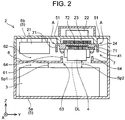
- FIG. 2 is a sectional view of a case 5 of the fuel cell unit 2.
- the case 5 is divided into a lower case 5a housing the fuel cell stack 3 and an upper case 5b connected on the upper side of the lower case 5a.
- the lower case 5a is provided with an intermediate plate 6 that partitions a space inside the case 5 into a lower space 61 and an upper space 62.
- the intermediate plate 6 is formed by aluminum die casting integrally with the lower case 5a. Alternatively, the intermediate plate 6 may be a part separate from the lower case 5a. In this case, the intermediate plate 6 is firmly fastened to the lower case 5a.
- the fuel cell stack 3 is a stack in which a plurality of single fuel cells 31 (see FIG. 4 ) is stacked.
- the lower case 5a (case 5) has a role of applying a load to the fuel cell stack 3 from both sides in a stacking direction of the single fuel cells.
- the intermediate plate 6 serves as a strength enhancing member that suppresses deformation of the lower case 5a when the lower case 5a applies a load to the fuel cell stack 3.
- the voltage converters 10a to 10d shown in FIG. 1 and various other components are housed in the upper case 5b (i.e., the upper space 62).
- the switching elements 12 and the rectifier diodes 13 shown in FIG. 1 are housed in a resin package.
- a stack 21 of a plurality of packages is housed in the upper space 62.
- the reactors 4 are also housed in the upper space 62.
- the reactors 4 are arrayed in an X-direction in the coordinate system of FIG. 2 . The array of the reactors 4 will be described later with reference to FIG. 4 and FIG. 5 .
- the reactor 4 has a structure in which a coil 41 is wound around a ring-shaped core 42 at two positions, and the core 42 and the coils 41 are covered with a resin cover 43.
- the core 42 is indicated by the dashed lines, as it is covered with the resin cover 43 and invisible.
- a projection 45 through which a bolt for fixing the reactor 4 is passed is provided at three positions in the resin cover 43 (one projection 45 is located on the rear side and therefore invisible in FIG. 3 ).
- Part of each coil 41 is exposed from the resin cover 43.
- the entire surface of one side (the lower surface in FIG. 3 ) of each coil 41 is exposed from the resin cover 43.
- Part of the surface of another side (the upper surface in FIG. 3 ) of each coil 41 is exposed through a window 43a provided in the resin cover 43.
- a lead 41a of each coil 41 is shown in FIG. 3 .
- FIG. 3 The reactor 4 shown in FIG. 3 is shown upside down in FIG. 2 . Specifically, the lower sides of the coils 41 are exposed from the resin cover 43 in FIG. 3 , while the upper sides of the coils 41 are exposed in FIG. 2 .
- a coolant flow passage 23 is formed above the reactor 4.
- the coolant flow passage 23 is a space surrounded by part of the upper case 5b, a pair of ridges 51 protruding inward from the upper case 5b, and a flow passage bottom plate 7.
- a liquid coolant flows through the coolant flow passage 23.
- the ridges 51 form side walls of the coolant flow passage 23.
- the flow passage bottom plate 7 is in contact with lower surfaces of the ridges 51 through a seal material or a gasket (neither is shown). In other words, the flow passage bottom plate 7 closes the lower side of the coolant flow passage 23.
- the seal material or the gasket prevents the coolant from leaking from between the ridges 51 and the flow passage bottom plate 7.
- An inverter 22 that drives a fuel cell pump (not shown) is disposed on a top plate of the upper case 5b that corresponds to an upper plate of the coolant flow passage 23.
- the inverter 22 is thermally coupled to the coolant flow passage 23 through the top plate, and is cooled by the coolant flowing through the coolant flow passage 23.
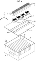
- FIG. 4 is an exploded perspective view of the lower case 5a housing the fuel cell stack 3, the intermediate plate 6, the reactors 4, and the flow passage bottom plate 7, as separated from one another in the up-down direction.
- FIG. 5 is a perspective view of the flow passage bottom plate 7 and the reactors 4 as seen from the lower side in FIG. 4 .
- FIG. 6 is a sectional view of the flow passage bottom plate 7 and the reactors 4 as cut along an XZ-plane indicated in FIG. 6 .
- the installation structure of the reactors 4 will be described with reference to FIG. 4 to FIG. 6 along with FIG. 2 .
- the fuel cell stack 3 is housed in the lower case 5a (i.e., the lower space 61).
- the fuel cell stack 3 is a stack in which the single fuel cells 31 are stacked.
- the X-direction in FIG. 4 corresponds to the stacking direction of the single fuel cells 31 (see FIG. 4 ). In the other drawings, too, the X-direction in the coordinate system indicated therein corresponds to the stacking direction of the single fuel cells 31.
- the lower case 5a is provided with a presser plate 32 that applies a load to the fuel cell stack 3.
- the case 5 applies a load in the stacking direction of the single fuel cells 31 through the presser plate 32 to the fuel cell stack 3.
- One end of the fuel cell stack 3 in the stacking direction is in contact with an inner surface of the lower case 5a, and the presser plate 32 applies a load to the fuel cell stack 3 from the other end side.
- the reactors 4 are arrayed along the X-direction in the drawings, and are fixed to the lower surface of the flow passage bottom plate 7 that is long in the X-direction.
- the projection 45 is provided at three positions in the resin cover of the reactor 4.
- FIG. 5 three fixing bolts 46 are depicted for only the reactor 4 on the left, while the bolts for the other reactors 4 are not shown.
- the bolt 46 passed through the projection 45 of the reactor 4 engages in a screw hole of a projection 75 provided on the flow passage bottom plate 7, and the reactor 4 is thereby fixed to the flow passage bottom plate 7 (see FIG. 5 ).
- FIG. 5 not only the projections 75 corresponding to the reactor 4 on the left but also those corresponding to the other reactors 4 are provided.
- the heat transfer sheets 24 are sandwiched between the coils 41 of the reactor 4 and the flow passage bottom plate 7. As shown in FIG. 5 , not only the heat transfer sheets 24 corresponding to the reactor 4 on the right but also those corresponding to the other reactors 4 are provided.
- the coils 41 of the reactor 4 are thermally coupled to the flow passage bottom plate 7 through the heat transfer sheets 24.
- a plurality of fins 72 is provided on the upper surface of the flow passage bottom plate 7, i.e., on the surface exposed to the coolant flow passage 23 (see FIG. 2 and FIG. 4 ).
- the coils 41 of the reactor 4 generate heat when a current flows therethrough. The heat of the coils 41 is efficiently absorbed by the coolant through the heat transfer sheets 24 and the fins 72.
- the reactors 4 are housed in the upper space 62 so as to be located above the fuel cell stack 3.
- the fuel cell stack 3 is housed in the lower space 61, with a predetermined clearance Sp1 provided between the intermediate plate 6 and the fuel cell stack 3.
- upper portions of the reactors 4 are fixed to the flow passage bottom plate 7, and there is a space on the lower side of the reactors 4.
- the intermediate plate 6 is provided with a through-hole 63 that is elongated in the X-direction (see FIG. 2 and FIG. 4 ).
- the through-hole 63 is provided in the intermediate plate 6 so as to be located below the reactors 4 (see FIG. 2 and FIG. 4 ).
- the through-hole 63 is at least large enough for the lower portions of the reactors 4 to pass through.
- the reactors 4 are disposed so that the lower portions thereof closely face the through-hole 63. In other words, the lower surfaces of the reactors 4 faces an upper surface of the fuel cell stack 3 through the through-hole 63.
- the lower portion of the reactor 4 means a portion up to a predetermined height (e.g., 1 cm) from a lower end of the reactor.
- the clearance Sp1 between the intermediate plate 6 and the fuel cell stack 3 is a clearance that is provided so that the fuel cell stack 3 does not come in contact with the intermediate plate 6.
- the clearance Sp1 is provided also to provide a space for the cable etc. to pass through.
- the through-hole 63 allows the clearance that should be provided on the lower side of the reactors 4 to overlap the clearance (clearance Sp1) provided above the fuel cell stack 3, and thus contributes to reducing the space for these clearances. Since the upper portions of the reactors 4 are fixed to the case 5 and a clearance is provided below the reactors 4, it is possible to overlap the clearance below the reactors 4 with the clearance provided above the fuel cell stack 3.
- the clearance (space) Sp1 shown in FIG. 2 is a clearance provided between the fuel cell stack 3 and the intermediate plate 6.
- the clearance (space) Sp2 is a clearance between the fuel cell stack 3 and the reactors 4. As shown in FIG. 2 , overlapping the space for securing a clearance for the fuel cell stack 3 and the space for securing a clearance for the reactors 4 can reduce the space required for these clearances in the fuel cell unit 2 of this embodiment.
- the reactors 4 are fixed to the upper case 5b through the flow passage bottom plate 7 so that the lower ends of the reactors 4 do not protrude downward beyond the intermediate plate 6.
- the reactors 4 are fixed to the upper case 5b through the flow passage bottom plate 7 so that the lower ends of the reactors 4 are located at a level equal to or higher than a lower surface of the intermediate plate 6 (the dashed line DL in FIG. 2 ). This is to prevent the fuel cell stack 3 from getting damaged on contact with the lower ends of the reactors 4 in the event that the vehicle collides and the case 5 is crushed by the impact.
- the reactors 4 are preferably fixed so that the lower ends thereof are substantially flush with the lower surface of the intermediate plate 6.
- the reactors 4 are disposed so that the lower portions thereof closely face the through-hole 63" is an arrangement in which the lower ends of the reactors 4 are disposed between the first ribs 64.
- the reactors 4 can be disposed at a lower level than when the through-hole 63 is not provided.
- the through-hole 63 is elongated in the stacking direction of the single fuel cells 31 (the X-direction in the drawings), and the reactors 4 are arrayed along the X-direction, i.e., the stacking direction.
- the lower case 5a applies a load in the stacking direction (the X-direction in the drawings) to the fuel cell stack 3.
- the intermediate plate 6 is a member that is integral with the lower case 5a (case 5) and serves to secure the strength of the lower case 5a (case 5) in the X-direction in the drawings.
- the reactors 4 are arrayed in the X-direction, and the through-hole 63 is elongated in the X-direction, so as to minimize the width of the through-hole 63 in the Y-direction.
- This structure can secure the strength of the lower case 5a in the X-direction.
- the first rib 64 is provided on the upper surface of the intermediate plate 6, on each side of the through-hole 63 in the Y-direction. Both ends of the first ribs 64 are in contact with an inner surface of the lower case 5a (case 5). The first ribs 64 enhance the strength of the intermediate plate 6, as well as prevent water having fallen on the intermediate plate 6 from falling through the through-hole 63 onto the fuel cell stack 3.
- the liquid coolant can leak from the coolant flow passage 23.
- the flow passage bottom plate 7 is joined to the lower surfaces of the ridges 51 through a seal material or a gasket (neither is shown).
- the liquid coolant can leak from joint areas between the flow passage bottom plate 7 and the ridges 51 (the areas indicated by the arrows A in FIG. 2 ).
- the fuel cell unit 2 of the embodiment has a feature that prevents any coolant that may leak from the joint areas A from falling through the through-hole 63 onto the fuel cell stack 3. This feature will be described next.
- a second rib 71 extending in the X-direction is provided at each end of the lower surface of the flow passage bottom plate 7 in the Y-direction.
- the first ribs 64 provided on the intermediate plate 6 are located between the two second ribs 71, below the flow passage bottom plate 7. According to this structure, if a coolant leaks from the joint areas between the flow passage bottom plate 7 and the ridges 51 (the areas indicated by the arrows A in FIG. 2 ), this leaking coolant falls onto the intermediate plate 6 by running down the outer side of the second ribs 71.
- the coolant falls at a position in the intermediate plate 6 on the outer side of the first ribs 64 (the opposite side from the through-hole 63).
- the coolant having fallen on the upper surface of the intermediate plate 6 is blocked by the first ribs 64 from falling through the through-hole 63.
- Both ends of the first ribs 64 are in contact with the inner surface of the lower case 5a (case 5).
- an annular first rib may be provided so as to surround the through-hole 63. Such an annular first rib can also prevent the liquid coolant from falling onto the fuel cell stack 3.
- a plurality of fins 72 extending in the X-direction is provided on the upper surface (the surface exposed to the coolant) of the flow passage bottom plate 7.
- a third rib 74 extending in the Y-direction is provided between the adjacent reactors 4, on the lower surface (the surface coming in contact with the reactors 4) of the flow passage bottom plate 7.
- the extension direction of the fins 72 (X-direction) and the extension direction of the third ribs 74 (Y-direction) intersect with each other.
- the rigidity of the flow passage bottom plate 7 is enhanced by the fins 72 and the third ribs 74 intersecting with each other.
- the flow passage bottom plate 7 becomes less likely to deform. It is therefore less likely that a gap is left between the flow passage bottom plate 7 and the ridges 51. As a result, the coolant is less likely to leak from between the flow passage bottom plate 7 and the ridges 51.
- FIG. 7 shows fins 172 in a modified example. Like the fins 172, the fin extending in the X-direction may terminate at an intermediate point in the X-direction.
- the fuel cell unit 2 of the embodiment includes four reactors 4. However, the number of the reactor 4 is not limited to four.
Landscapes
- Engineering & Computer Science (AREA)
- Life Sciences & Earth Sciences (AREA)
- Sustainable Development (AREA)
- Sustainable Energy (AREA)
- Power Engineering (AREA)
- Chemical Kinetics & Catalysis (AREA)
- Manufacturing & Machinery (AREA)
- Chemical & Material Sciences (AREA)
- Electrochemistry (AREA)
- General Chemical & Material Sciences (AREA)
- Mechanical Engineering (AREA)
- Transportation (AREA)
- Fuel Cell (AREA)
Abstract
Description
- A technique to be disclosed by the present specification relates to a fuel cell unit. More particularly, the present specification relates to a technique for reducing a space that is required to provide a clearance inside a case of a fuel cell unit. The clearance here means an extra distance to be provided between a component housed in the case and an inner surface of the case, or an extra distance to be provided between components.
- Fuel cells have been attracting attention as a source of electrical power for vehicles. For example, Japanese Patent Application Publication No.
2014-83875 JP 2014-83875 A - Vehicles are subject to extremely severe restrictions on parts installation space, which require all the parts to be downsized. However, an electrical device requires a predetermined extra distance (clearance) to be provided between a component housed in a case and an inner surface of the case or between components. The fuel cell unit of
JP 2014-83875 A JP 2014-83875 A - A fuel cell unit to be disclosed by the present specification includes a fuel cell stack in which a plurality of single fuel cells is stacked, an electrical component that is electrically connected to the fuel cell stack, and a case that houses the fuel cell stack and the electrical component. The case is provided with an intermediate plate that partitions a space inside the case into an upper space and a lower space. The fuel cell stack is housed in the lower space, with a predetermined clearance provided between the intermediate plate and the fuel cell stack. The electrical component is housed in the upper space above the fuel cell stack, with an upper portion of the electrical component fixed to the case. A through-hole that is large enough for a lower portion of the electrical component to pass through is provided in the intermediate plate at a position below the electrical component, and the lower portion of the electrical component faces the through-hole. The electrical component may be directly fixed to the case, or may be fixed to the case through another member.
- In the above fuel cell unit, the electrical component is fixed in the upper portion, and a clearance is required on the lower side of the electrical component. The intermediate plate that partitions the space inside the case is present on the lower side of the electrical component, and this intermediate plate is provided with the through-hole that is large enough for the lower portion of the electrical component to pass through. Thus, the clearance on the lower side of the electrical component can be provided between the electrical component and the fuel cell stack housed in the lower space. On the other hand, the fuel cell stack is housed in the lower space, with a predetermined clearance provided between the fuel cell stack and the intermediate plate above the fuel cell stack. The clearance on the lower side of the electrical component may overlap the clearance on the upper side of the fuel cell stack. Unlike the fuel cell unit of
JP 2014-83875 A - The electrical component may be typically a reactor of a voltage converter configured to change the voltage output by the fuel cell stack.
- To distribute a load on a voltage converter, a plurality of voltage converters connected in parallel to one another is sometimes used. In this case, a plurality of reactors is required. A large through-hole that allows passage of lower portions of these reactors is required in the intermediate plate of the case. However, the case has a role of applying a load to the fuel cell stack along a cell stacking direction. Providing a large through-hole in the intermediate plate may reduce the rigidity of the case that supports the load applied to the fuel cell stack. As a solution, a thorough-hole that is elongated in the cell stacking direction may be provided in the intermediate plate, and the reactors may be arrayed along a long-side direction of the through-hole. Such a through-hole elongated in the cell stacking direction can avoid reducing the rigidity of the case in the stacking direction (the stacking direction of the single fuel cells).
- At least one first rib including at least one portion extending along the long-side direction may be provided on an upper surface of the intermediate plate, on each side of the elongated through-hole in a short-side direction thereof. Moreover, (i) the at least first rib surround the through-hole, or (ii) the at least one first rib may include two first ribs, and the ends of the two first ribs in the long-side direction are connected to an inner surface of the case. The first ribs enhance the strength of the case, as well as prevent water droplets having fallen on the intermediate plate from falling through the through-hole onto the fuel cell stack.
- Since the reactor is a component that generates heat during operation, a coolant flow passage for cooling the reactor may be required inside the case. In this case, it is desirable that, even if a liquid coolant leaks from the coolant flow passage, this leaking coolant is prevented from falling through the through-hole onto the fuel cell stack. For this purpose, the following structure can be adopted. A coolant flow passage is provided inside the case, above the reactors. The reactors are fixed to a flow passage bottom plate that closes the lower side of the coolant flow passage. Two second ribs extending along the long-side direction are provided on a lower surface of the flow passage bottom plate. The above-described first ribs are located between the two second ribs, below the flow passage bottom plate. In this configuration, any coolant leaking from between joint surfaces of a side wall of the coolant flow passage and the flow passage bottom plate falls onto the intermediate plate by running down the outer side of the second rib of the flow passage bottom plate. Since the leaking coolant falls at a position on the outer side of the first rib (the opposite side from the through-hole), the falling coolant will not fall through the through-hole onto the fuel cell stack.
- The flow passage bottom plate may further include the following configuration. A plurality of fins extending along the long-side direction is provided on an upper surface of the flow passage bottom plate. A third rib extending in the short-side direction is provided between the adjacent reactors, on the lower surface of the flow passage bottom plate. According to this configuration, the strength of the flow passage bottom plate is enhanced by the fins and the third ribs that extend so as to intersect with each other. As the fins and the third ribs limit deformation of the flow passage bottom plate, the coolant is less likely to leak from the coolant flow passage.
- A lower end of the electrical component may be located at a level equal to or higher than a lower surface of the intermediate plate, and a distance between the lower end of the electrical component and the lower surface of the intermediate plate may be shorter than a predetermined distance.
- Features, advantages, and technical and industrial significance of exemplary embodiments of the invention will be described below with reference to the accompanying drawings, in which like numerals denote like elements, and wherein:
-
FIG. 1 is a block diagram of an electrical vehicle including a fuel cell unit; -
FIG. 2 is a sectional view of a case of the fuel cell unit; -
FIG. 3 is a perspective view of a reactor; -
FIG. 4 is a perspective view of the case, an intermediate plate, the reactor, and a flow passage bottom plate; -
FIG. 5 is a perspective view of the flow passage bottom plate and a plurality of reactors as seen from an obliquely lower side; -
FIG. 6 is a sectional view of the flow passage bottom plate and the reactors as cut along a long-side direction of the flow passage bottom plate; and -
FIG. 7 is a sectional view illustrating a modified example of the shape of fins. - A fuel cell unit of an embodiment will be described with reference to the drawings. First, an electrical circuit of the fuel cell unit will be described with reference to
FIG. 1. FIG. 1 is a block diagram of anelectrical vehicle 100 including afuel cell unit 2. Thefuel cell unit 2 incudes afuel cell stack 3, a plurality ofvoltage converters 10a to 10d, and a smoothingcapacitor 14. Although thefuel cell unit 2 also includes a pump and other components, these are not shown in the drawings. - The
voltage converters 10a to 10d are connected in parallel to one another. Thevoltage converters 10a to lOd change the output voltage of thefuel cell stack 3. Specifically, thevoltage converters 10a to 10d raise the output voltage of thefuel cell stack 3. Thevoltage converters 10a to 10d each include areactor 4, a switchingelement 12, and arectifier diode 13. Thereactor 4 is connected to a positive electrode line of thefuel cell stack 3. Therectifier diode 13 is connected on the side of thereactor 4 closer to a secondary battery 91 (to be described later). Therectifier diode 13 is connected in such a direction that a current flows from thereactor 4 to thesecondary battery 91. The switchingelement 12 is connected to a line between thereactor 4 and therectifier diode 13, and a negative electrode line such that the switchingelement 12 is disposed between the lines. When the switchingelement 12 is operated at an appropriate duty ratio, electrical power with a raised voltage is output to thesecondary battery 91 according to the duty ratio. - The smoothing
capacitor 14 is connected in parallel to thevoltage converters 10a to 10d, on the output side thereof. The smoothingcapacitor 14 cancels pulsation of the output current of thevoltage converters 10a to 10d. - An
inverter 93 is connected on the output side of thevoltage converters 10a to 10d. Atraction motor 94 is connected to the alternating-current side of theinverter 93. A bidirectional DC-DC converter 92 is connected between the output side of thevoltage converters 10a to 10d and theinverter 93. Thesecondary battery 91 is connected on the farther side of the bidirectional DC-DC converter 92. Theinverter 93 converts direct-current power into alternating-current power and outputs this alternating-current power to themotor 94. Theinverter 93 also functions to convert alternating-current power generated by the motor 94 (regenerated power) into direct-current power. - The bidirectional DC-
DC converter 92 has step-up and step-down functions. The step-up function is a function of raising the output voltage of thesecondary battery 91 and supplies this output voltage to theinverter 93. The step-down function is a function of lowering the voltage of regenerated power that has been generated by themotor 94 and converted by theinverter 93 from alternating-current power into direct-current power, and supplying this regenerated power to thesecondary battery 91. Theinverter 93 converts direct-current power sent from the bidirectional DC-DC converter 92 and thefuel cell unit 2 into alternating-current power suitable for driving themotor 94, and outputs this alternating-current power. As described above, in some cases, theinverter 93 converts alternating-current power generated by themotor 94 during deceleration of the vehicle (regenerated power) into direct-current power. - The time constant of a change in output of the
fuel cell stack 3 is longer than the time constant required for thetraction motor 94. In other words, the response speed of the output of thefuel cell stack 3 is less than the response speed required for themotor 94. Thesecondary battery 91 is provided to compensate for electrical power output by thefuel cell stack 3 and to absorb extra electrical power of thefuel cell stack 3. As described above, thesecondary battery 91 also stores regenerated power. - As shown in
FIG. 1 , thefuel cell unit 2 includes thefuel cell stack 3, and thereactors 4 electrically connected to thefuel cell stack 3. In the following, the arrangement of thefuel cell stack 3 and thereactors 4 inside a case of thefuel cell unit 2 and the structure of this case will be described. -
FIG. 2 is a sectional view of acase 5 of thefuel cell unit 2. Thecase 5 is divided into alower case 5a housing thefuel cell stack 3 and anupper case 5b connected on the upper side of thelower case 5a. Thelower case 5a is provided with anintermediate plate 6 that partitions a space inside thecase 5 into alower space 61 and anupper space 62. Theintermediate plate 6 is formed by aluminum die casting integrally with thelower case 5a. Alternatively, theintermediate plate 6 may be a part separate from thelower case 5a. In this case, theintermediate plate 6 is firmly fastened to thelower case 5a. - The
fuel cell stack 3 is a stack in which a plurality of single fuel cells 31 (seeFIG. 4 ) is stacked. Thelower case 5a (case 5) has a role of applying a load to thefuel cell stack 3 from both sides in a stacking direction of the single fuel cells. Theintermediate plate 6 serves as a strength enhancing member that suppresses deformation of thelower case 5a when thelower case 5a applies a load to thefuel cell stack 3. - The
voltage converters 10a to 10d shown inFIG. 1 and various other components are housed in theupper case 5b (i.e., the upper space 62). The switchingelements 12 and therectifier diodes 13 shown inFIG. 1 are housed in a resin package. Astack 21 of a plurality of packages is housed in theupper space 62. Thereactors 4 are also housed in theupper space 62. Thereactors 4 are arrayed in an X-direction in the coordinate system ofFIG. 2 . The array of thereactors 4 will be described later with reference toFIG. 4 andFIG. 5 . - Here, the structure of the
reactor 4 will be descried with reference toFIG. 3 . Thereactor 4 has a structure in which acoil 41 is wound around a ring-shapedcore 42 at two positions, and thecore 42 and thecoils 41 are covered with aresin cover 43. InFIG. 3 , thecore 42 is indicated by the dashed lines, as it is covered with theresin cover 43 and invisible. Aprojection 45 through which a bolt for fixing thereactor 4 is passed is provided at three positions in the resin cover 43 (oneprojection 45 is located on the rear side and therefore invisible inFIG. 3 ). Part of eachcoil 41 is exposed from theresin cover 43. The entire surface of one side (the lower surface inFIG. 3 ) of eachcoil 41 is exposed from theresin cover 43. Part of the surface of another side (the upper surface inFIG. 3 ) of eachcoil 41 is exposed through awindow 43a provided in theresin cover 43. A lead 41a of eachcoil 41 is shown inFIG. 3 . - Referring back to
FIG. 2 , the structure of thecase 5 and the arrangement of thereactors 4 in theupper space 62 will be further described. Thereactor 4 shown inFIG. 3 is shown upside down inFIG. 2 . Specifically, the lower sides of thecoils 41 are exposed from theresin cover 43 inFIG. 3 , while the upper sides of thecoils 41 are exposed inFIG. 2 . - A
coolant flow passage 23 is formed above thereactor 4. Thecoolant flow passage 23 is a space surrounded by part of theupper case 5b, a pair ofridges 51 protruding inward from theupper case 5b, and a flow passagebottom plate 7. A liquid coolant flows through thecoolant flow passage 23. Theridges 51 form side walls of thecoolant flow passage 23. The flow passagebottom plate 7 is in contact with lower surfaces of theridges 51 through a seal material or a gasket (neither is shown). In other words, the flow passagebottom plate 7 closes the lower side of thecoolant flow passage 23. The seal material or the gasket prevents the coolant from leaking from between theridges 51 and the flow passagebottom plate 7. Aninverter 22 that drives a fuel cell pump (not shown) is disposed on a top plate of theupper case 5b that corresponds to an upper plate of thecoolant flow passage 23. Theinverter 22 is thermally coupled to thecoolant flow passage 23 through the top plate, and is cooled by the coolant flowing through thecoolant flow passage 23. - The
reactors 4 are fixed to a lower surface of the flow passagebottom plate 7. Since the flow passagebottom plate 7 is fixed to theupper case 5b, thereactors 4 are fixed to theupper case 5b (i.e., the case 5) through the flow passagebottom plate 7. One side surface of eachcoil 41 of thereactor 4 is thermally connected to the flow passagebottom plate 7 through aheat transfer sheet 24.FIG. 4 is an exploded perspective view of thelower case 5a housing thefuel cell stack 3, theintermediate plate 6, thereactors 4, and the flow passagebottom plate 7, as separated from one another in the up-down direction.FIG. 5 is a perspective view of the flow passagebottom plate 7 and thereactors 4 as seen from the lower side inFIG. 4 .FIG. 6 is a sectional view of the flow passagebottom plate 7 and thereactors 4 as cut along an XZ-plane indicated inFIG. 6 . In the following, the installation structure of thereactors 4 will be described with reference toFIG. 4 to FIG. 6 along withFIG. 2 . - The
fuel cell stack 3 is housed in thelower case 5a (i.e., the lower space 61). Thefuel cell stack 3 is a stack in which thesingle fuel cells 31 are stacked. The X-direction inFIG. 4 corresponds to the stacking direction of the single fuel cells 31 (seeFIG. 4 ). In the other drawings, too, the X-direction in the coordinate system indicated therein corresponds to the stacking direction of thesingle fuel cells 31. Thelower case 5a is provided with apresser plate 32 that applies a load to thefuel cell stack 3. Thecase 5 applies a load in the stacking direction of thesingle fuel cells 31 through thepresser plate 32 to thefuel cell stack 3. One end of thefuel cell stack 3 in the stacking direction is in contact with an inner surface of thelower case 5a, and thepresser plate 32 applies a load to thefuel cell stack 3 from the other end side. - The
reactors 4 are arrayed along the X-direction in the drawings, and are fixed to the lower surface of the flow passagebottom plate 7 that is long in the X-direction. As described above, theprojection 45 is provided at three positions in the resin cover of thereactor 4. InFIG. 5 , three fixingbolts 46 are depicted for only thereactor 4 on the left, while the bolts for theother reactors 4 are not shown. Thebolt 46 passed through theprojection 45 of thereactor 4 engages in a screw hole of aprojection 75 provided on the flow passagebottom plate 7, and thereactor 4 is thereby fixed to the flow passage bottom plate 7 (seeFIG. 5 ). As shown inFIG. 5 , not only theprojections 75 corresponding to thereactor 4 on the left but also those corresponding to theother reactors 4 are provided. - The
heat transfer sheets 24 are sandwiched between thecoils 41 of thereactor 4 and the flow passagebottom plate 7. As shown inFIG. 5 , not only theheat transfer sheets 24 corresponding to thereactor 4 on the right but also those corresponding to theother reactors 4 are provided. Thecoils 41 of thereactor 4 are thermally coupled to the flow passagebottom plate 7 through theheat transfer sheets 24. A plurality offins 72 is provided on the upper surface of the flow passagebottom plate 7, i.e., on the surface exposed to the coolant flow passage 23 (seeFIG. 2 andFIG. 4 ). Thecoils 41 of thereactor 4 generate heat when a current flows therethrough. The heat of thecoils 41 is efficiently absorbed by the coolant through theheat transfer sheets 24 and thefins 72. - As shown in
FIG. 2 , thereactors 4 are housed in theupper space 62 so as to be located above thefuel cell stack 3. Thefuel cell stack 3 is housed in thelower space 61, with a predetermined clearance Sp1 provided between theintermediate plate 6 and thefuel cell stack 3. On the other hand, upper portions of thereactors 4 are fixed to the flow passagebottom plate 7, and there is a space on the lower side of thereactors 4. Theintermediate plate 6 is provided with a through-hole 63 that is elongated in the X-direction (seeFIG. 2 andFIG. 4 ). The through-hole 63 is provided in theintermediate plate 6 so as to be located below the reactors 4 (seeFIG. 2 andFIG. 4 ). The through-hole 63 is at least large enough for the lower portions of thereactors 4 to pass through. Thereactors 4 are disposed so that the lower portions thereof closely face the through-hole 63. In other words, the lower surfaces of thereactors 4 faces an upper surface of thefuel cell stack 3 through the through-hole 63. The lower portion of thereactor 4 means a portion up to a predetermined height (e.g., 1 cm) from a lower end of the reactor. - The clearance Sp1 between the
intermediate plate 6 and thefuel cell stack 3 is a clearance that is provided so that thefuel cell stack 3 does not come in contact with theintermediate plate 6. When a cable etc. is passed through above thefuel cell stack 3, the clearance Sp1 is provided also to provide a space for the cable etc. to pass through. On the other hand, it is also necessary to provide a clearance on the lower side of thereactors 4 so that thereactors 4 do not come in contact with theintermediate plate 6, or to allow a cable etc. to pass through below thereactors 4. The through-hole 63 allows the clearance that should be provided on the lower side of thereactors 4 to overlap the clearance (clearance Sp1) provided above thefuel cell stack 3, and thus contributes to reducing the space for these clearances. Since the upper portions of thereactors 4 are fixed to thecase 5 and a clearance is provided below thereactors 4, it is possible to overlap the clearance below thereactors 4 with the clearance provided above thefuel cell stack 3. - The clearance (space) Sp1 shown in
FIG. 2 is a clearance provided between thefuel cell stack 3 and theintermediate plate 6. The clearance (space) Sp2 is a clearance between thefuel cell stack 3 and thereactors 4. As shown inFIG. 2 , overlapping the space for securing a clearance for thefuel cell stack 3 and the space for securing a clearance for thereactors 4 can reduce the space required for these clearances in thefuel cell unit 2 of this embodiment. - The
reactors 4 are fixed to theupper case 5b through the flow passagebottom plate 7 so that the lower ends of thereactors 4 do not protrude downward beyond theintermediate plate 6. In other words, thereactors 4 are fixed to theupper case 5b through the flow passagebottom plate 7 so that the lower ends of thereactors 4 are located at a level equal to or higher than a lower surface of the intermediate plate 6 (the dashed line DL inFIG. 2 ). This is to prevent thefuel cell stack 3 from getting damaged on contact with the lower ends of thereactors 4 in the event that the vehicle collides and thecase 5 is crushed by the impact. Thereactors 4 are preferably fixed so that the lower ends thereof are substantially flush with the lower surface of theintermediate plate 6. One example of the arrangement "thereactors 4 are disposed so that the lower portions thereof closely face the through-hole 63" is an arrangement in which the lower ends of thereactors 4 are disposed between thefirst ribs 64. Thus, thereactors 4 can be disposed at a lower level than when the through-hole 63 is not provided. - As shown in
FIG. 4 , the through-hole 63 is elongated in the stacking direction of the single fuel cells 31 (the X-direction in the drawings), and thereactors 4 are arrayed along the X-direction, i.e., the stacking direction. As described above, thelower case 5a applies a load in the stacking direction (the X-direction in the drawings) to thefuel cell stack 3. As described above, theintermediate plate 6 is a member that is integral with thelower case 5a (case 5) and serves to secure the strength of thelower case 5a (case 5) in the X-direction in the drawings. Providing theintermediate plate 6 with a through-hole that is wide in the Y-direction in the drawings would reduce the strength of thelower case 5a in the X-direction. In thefuel cell unit 2 of the embodiment, thereactors 4 are arrayed in the X-direction, and the through-hole 63 is elongated in the X-direction, so as to minimize the width of the through-hole 63 in the Y-direction. This structure can secure the strength of thelower case 5a in the X-direction. - The
first rib 64 is provided on the upper surface of theintermediate plate 6, on each side of the through-hole 63 in the Y-direction. Both ends of thefirst ribs 64 are in contact with an inner surface of thelower case 5a (case 5). Thefirst ribs 64 enhance the strength of theintermediate plate 6, as well as prevent water having fallen on theintermediate plate 6 from falling through the through-hole 63 onto thefuel cell stack 3. - The liquid coolant can leak from the
coolant flow passage 23. As described above, the flow passagebottom plate 7 is joined to the lower surfaces of theridges 51 through a seal material or a gasket (neither is shown). The liquid coolant can leak from joint areas between the flow passagebottom plate 7 and the ridges 51 (the areas indicated by the arrows A inFIG. 2 ). Thefuel cell unit 2 of the embodiment has a feature that prevents any coolant that may leak from the joint areas A from falling through the through-hole 63 onto thefuel cell stack 3. This feature will be described next. - As shown in
FIG. 2 andFIG. 4 , asecond rib 71 extending in the X-direction is provided at each end of the lower surface of the flow passagebottom plate 7 in the Y-direction. As shown inFIG. 2 , thefirst ribs 64 provided on theintermediate plate 6 are located between the twosecond ribs 71, below the flow passagebottom plate 7. According to this structure, if a coolant leaks from the joint areas between the flow passagebottom plate 7 and the ridges 51 (the areas indicated by the arrows A inFIG. 2 ), this leaking coolant falls onto theintermediate plate 6 by running down the outer side of thesecond ribs 71. The coolant falls at a position in theintermediate plate 6 on the outer side of the first ribs 64 (the opposite side from the through-hole 63). Thus, the coolant having fallen on the upper surface of theintermediate plate 6 is blocked by thefirst ribs 64 from falling through the through-hole 63. Both ends of thefirst ribs 64 are in contact with the inner surface of thelower case 5a (case 5). Instead of this structure, an annular first rib may be provided so as to surround the through-hole 63. Such an annular first rib can also prevent the liquid coolant from falling onto thefuel cell stack 3. - As shown in
FIG. 2 andFIG. 4 , a plurality offins 72 extending in the X-direction is provided on the upper surface (the surface exposed to the coolant) of the flow passagebottom plate 7. As shown inFIG. 5 , athird rib 74 extending in the Y-direction is provided between theadjacent reactors 4, on the lower surface (the surface coming in contact with the reactors 4) of the flow passagebottom plate 7. The extension direction of the fins 72 (X-direction) and the extension direction of the third ribs 74 (Y-direction) intersect with each other. The rigidity of the flow passagebottom plate 7 is enhanced by thefins 72 and thethird ribs 74 intersecting with each other. As the rigidity of the flow passagebottom plate 7 is enhanced, the flow passagebottom plate 7 becomes less likely to deform. It is therefore less likely that a gap is left between the flow passagebottom plate 7 and theridges 51. As a result, the coolant is less likely to leak from between the flow passagebottom plate 7 and theridges 51. -
FIG. 7 shows fins 172 in a modified example. Like thefins 172, the fin extending in the X-direction may terminate at an intermediate point in the X-direction. - Here is one point to note on the technique having been described in the embodiment: The
fuel cell unit 2 of the embodiment includes fourreactors 4. However, the number of thereactor 4 is not limited to four. - While the specific examples of the present invention have been described in detail above, these examples are merely illustrative and do not limit the present invention. The present invention includes the above-illustrated specific examples with various modifications and changes added thereto, within the scope of the claims. The technical elements described in the present specification or the drawings exhibit technical utility independently or in various combinations, without limiting the present invention. The technique illustrated in the present specification or the drawings can achieve a plurality of objects at the same time, and has technical utility simply by achieving one of these objects.
Claims (7)
- A fuel cell unit (2) comprising:a fuel cell stack (3) in which a plurality of single fuel cells is stacked;an electrical component (4) that is electrically connected to the fuel cell stack (3); anda case (5) housing the fuel cell stack (3) and the electrical component (4),wherein the case (5) is provided with an intermediate plate (6) that partitions a space inside the case (5) into an upper space (62) and a lower space (61),wherein the fuel cell stack (3) is housed in the lower space (61), with a predetermined clearance provided between the intermediate plate (6) and the fuel cell stack (3),wherein the electrical component (4) is housed in the upper space (62) above the fuel cell stack (3), with an upper portion of the electrical component (4) fixed to the case (5),wherein a through-hole (63) that is large enough for a lower portion of the electrical component (4) to pass through is provided in the intermediate plate (6) at a position below the electrical component (4), andwherein the lower portion of the electrical component (4) faces the through-hole (63).
- The fuel cell unit according to claim 1, wherein
the electrical component (4) is a reactor of a voltage converter configured to change an output voltage of the fuel cell stack (3). - The fuel cell unit according to claim 2, wherein
the case (5) is configured to apply a load to the fuel cell stack (3) along a stacking direction of the single fuel cells;
the through-hole (63) is elongated in the stacking direction; and
a plurality of reactors is arrayed along a long-side direction of the through-hole (63). - The fuel cell unit according to claim 3, wherein
at least one first rib (64) including at least one portion extending along the long-side direction is provided on an upper surface of the intermediate plate (6), on each side of the elongated through-hole (63) in a short-side direction thereof; and(i) the at least one first rib (64) surrounds the through-hole (63), or (ii) the at least one first rib (64) includes two first ribs, and ends of the two first ribs (64) in the long-side direction are connected to an inner surface of the case (5). - The fuel cell unit according to claim 4, wherein
a coolant flow passage is provided inside the case (5), above the reactors;
the reactors are fixed to a flow passage bottom plate (7) that closes a lower side of the coolant flow passage;
two second ribs (71) extending along the long-side direction are provided on a lower surface of the flow passage bottom plate (7); and
the first ribs (64) are located between the two second ribs (71), below the flow passage bottom plate (7). - The fuel cell unit according to claim 5, wherein
a plurality of fins (72) extending along the long-side direction is provided on an upper surface of the flow passage bottom plate (7), and a third rib (74) extending in the short-side direction is provided between the adjacent reactors, on the lower surface of the flow passage bottom plate (7). - The fuel cell unit according to any one of claims 1 to 6, wherein
a lower end of the electrical component (4) is located at a level equal to or higher than a lower surface of the intermediate plate (6), and a distance between the lower end of the electrical component (4) and the lower surface of the intermediate plate (6) is shorter than a predetermined distance.
Applications Claiming Priority (1)
| Application Number | Priority Date | Filing Date | Title |
|---|---|---|---|
| JP2017061543A JP6673275B2 (en) | 2017-03-27 | 2017-03-27 | Fuel cell unit |
Publications (2)
| Publication Number | Publication Date |
|---|---|
| EP3382784A1 true EP3382784A1 (en) | 2018-10-03 |
| EP3382784B1 EP3382784B1 (en) | 2020-01-01 |
Family
ID=61800391
Family Applications (1)
| Application Number | Title | Priority Date | Filing Date |
|---|---|---|---|
| EP18163975.8A Active EP3382784B1 (en) | 2017-03-27 | 2018-03-26 | Fuel cell unit comprising casing incorporating fuel cell stack and electrical component |
Country Status (7)
| Country | Link |
|---|---|
| US (1) | US10828992B2 (en) |
| EP (1) | EP3382784B1 (en) |
| JP (1) | JP6673275B2 (en) |
| KR (1) | KR102024018B1 (en) |
| CN (1) | CN108666605B (en) |
| BR (1) | BR102018005661A2 (en) |
| RU (1) | RU2677822C1 (en) |
Cited By (1)
| Publication number | Priority date | Publication date | Assignee | Title |
|---|---|---|---|---|
| EP3866240A1 (en) * | 2020-02-12 | 2021-08-18 | Denso Corporation | Fuel cell unit |
Families Citing this family (11)
| Publication number | Priority date | Publication date | Assignee | Title |
|---|---|---|---|---|
| JP6758264B2 (en) * | 2017-08-10 | 2020-09-23 | 株式会社デンソー | Reactor cooling structure |
| JP7136014B2 (en) * | 2019-06-07 | 2022-09-13 | トヨタ自動車株式会社 | fuel cell unit |
| JP7159992B2 (en) | 2019-07-29 | 2022-10-25 | トヨタ自動車株式会社 | fuel cell module |
| JP7136040B2 (en) | 2019-08-06 | 2022-09-13 | トヨタ自動車株式会社 | fuel cell unit |
| JP7136044B2 (en) * | 2019-08-09 | 2022-09-13 | トヨタ自動車株式会社 | fuel cell unit |
| US11676504B1 (en) * | 2019-08-13 | 2023-06-13 | Amplify Education, Inc. | Adaptive educational activities |
| JP2021034430A (en) * | 2019-08-19 | 2021-03-01 | 株式会社デンソー | Reactor unit |
| JP7151686B2 (en) * | 2019-10-15 | 2022-10-12 | トヨタ自動車株式会社 | Power converter controller and fuel cell system |
| KR20210057499A (en) * | 2019-11-12 | 2021-05-21 | 현대자동차주식회사 | Fuel cell vehicle |
| US11557419B2 (en) | 2020-06-23 | 2023-01-17 | Hamilton Sundstrand Corporation | Thermal management of inductor on a cold plate |
| KR20220090986A (en) * | 2020-12-23 | 2022-06-30 | 현대자동차주식회사 | Fuel cell vehicle |
Citations (6)
| Publication number | Priority date | Publication date | Assignee | Title |
|---|---|---|---|---|
| US20020192521A1 (en) * | 2001-06-14 | 2002-12-19 | Stephen Raiser | Electrical isolation system for a fuel cell stack and method of operating a fuel cell stack |
| US20120295173A1 (en) * | 2007-12-05 | 2012-11-22 | Panasonic Corporation | Fuel cell power generation system |
| US20140110185A1 (en) * | 2012-10-19 | 2014-04-24 | Honda Motor Co., Ltd. | Fuel cell power plant provided in vehicle |
| WO2014136553A1 (en) * | 2013-03-06 | 2014-09-12 | Honda Motor Co., Ltd. | Fuel cell system |
| EP2827428A1 (en) * | 2012-03-13 | 2015-01-21 | Nissan Motor Co., Ltd. | Vehicle-mounted cell stack system |
| US20170069923A1 (en) * | 2015-09-08 | 2017-03-09 | Bloom Energy Corporation | Fuel cell ventilation systems |
Family Cites Families (17)
| Publication number | Priority date | Publication date | Assignee | Title |
|---|---|---|---|---|
| JPH0922719A (en) * | 1995-07-05 | 1997-01-21 | Sanyo Electric Co Ltd | Portable fuel cell and its operating method |
| JP2002231292A (en) * | 2001-01-31 | 2002-08-16 | Daikin Ind Ltd | Fuel cell and fuel cell-driven cooling-freezing device |
| JP4118130B2 (en) * | 2002-11-28 | 2008-07-16 | トヨタ自動車株式会社 | Electric car |
| JP4991097B2 (en) * | 2004-09-16 | 2012-08-01 | 京セラ株式会社 | Fuel cell power generator |
| US20070087241A1 (en) * | 2005-10-18 | 2007-04-19 | General Hydrogen Corporation | Fuel cell power pack |
| JP4910365B2 (en) * | 2005-11-04 | 2012-04-04 | トヨタ自動車株式会社 | Fuel cell stack, fuel cell system, and mobile body equipped with the system |
| JP4739166B2 (en) * | 2006-10-24 | 2011-08-03 | 本田技研工業株式会社 | Gas sensor |
| JP5042143B2 (en) * | 2007-12-05 | 2012-10-03 | パナソニック株式会社 | Fuel cell power generation system |
| KR20100114686A (en) | 2009-04-16 | 2010-10-26 | 삼성전자주식회사 | Fuel cell stack and fuel cell system with a plurality of generation modules |
| JP2011253730A (en) * | 2010-06-02 | 2011-12-15 | Toyota Motor Corp | Fuel cell stack |
| JP5126343B2 (en) * | 2010-11-17 | 2013-01-23 | ダイキン工業株式会社 | Air conditioner |
| JP5810257B2 (en) * | 2011-03-18 | 2015-11-11 | パナソニックIpマネジメント株式会社 | Fuel cell system |
| WO2012150629A1 (en) * | 2011-05-02 | 2012-11-08 | トヨタ自動車株式会社 | Fuel cell vehicle |
| JP5057601B2 (en) * | 2012-06-05 | 2012-10-24 | パナソニック株式会社 | Fuel cell power generation system |
| CN203326035U (en) | 2013-06-25 | 2013-12-04 | 航天新长征电动汽车技术有限公司 | Rack of small-size fuel cell mobile power station |
| US9538691B2 (en) * | 2015-04-15 | 2017-01-03 | Ford Global Technologies, Llc | Power inverter for a vehicle |
| RU167197U1 (en) * | 2016-04-18 | 2016-12-27 | Федеральное государственное унитарное предприятие "Крыловский государственный научный центр" | MODULAR MONOBLOCK POWER INSTALLATION ON FUEL ELEMENTS FOR UNDERWATER UNIT |
-
2017
- 2017-03-27 JP JP2017061543A patent/JP6673275B2/en active Active
-
2018
- 2018-03-20 US US15/926,426 patent/US10828992B2/en active Active
- 2018-03-20 KR KR1020180031809A patent/KR102024018B1/en active IP Right Grant
- 2018-03-22 BR BR102018005661A patent/BR102018005661A2/en not_active Application Discontinuation
- 2018-03-22 CN CN201810240032.7A patent/CN108666605B/en not_active Expired - Fee Related
- 2018-03-23 RU RU2018110273A patent/RU2677822C1/en active
- 2018-03-26 EP EP18163975.8A patent/EP3382784B1/en active Active
Patent Citations (6)
| Publication number | Priority date | Publication date | Assignee | Title |
|---|---|---|---|---|
| US20020192521A1 (en) * | 2001-06-14 | 2002-12-19 | Stephen Raiser | Electrical isolation system for a fuel cell stack and method of operating a fuel cell stack |
| US20120295173A1 (en) * | 2007-12-05 | 2012-11-22 | Panasonic Corporation | Fuel cell power generation system |
| EP2827428A1 (en) * | 2012-03-13 | 2015-01-21 | Nissan Motor Co., Ltd. | Vehicle-mounted cell stack system |
| US20140110185A1 (en) * | 2012-10-19 | 2014-04-24 | Honda Motor Co., Ltd. | Fuel cell power plant provided in vehicle |
| WO2014136553A1 (en) * | 2013-03-06 | 2014-09-12 | Honda Motor Co., Ltd. | Fuel cell system |
| US20170069923A1 (en) * | 2015-09-08 | 2017-03-09 | Bloom Energy Corporation | Fuel cell ventilation systems |
Cited By (1)
| Publication number | Priority date | Publication date | Assignee | Title |
|---|---|---|---|---|
| EP3866240A1 (en) * | 2020-02-12 | 2021-08-18 | Denso Corporation | Fuel cell unit |
Also Published As
| Publication number | Publication date |
|---|---|
| KR20180109699A (en) | 2018-10-08 |
| CN108666605B (en) | 2021-09-07 |
| EP3382784B1 (en) | 2020-01-01 |
| KR102024018B1 (en) | 2019-09-24 |
| JP6673275B2 (en) | 2020-03-25 |
| US20180272889A1 (en) | 2018-09-27 |
| CN108666605A (en) | 2018-10-16 |
| JP2018163846A (en) | 2018-10-18 |
| RU2677822C1 (en) | 2019-01-21 |
| US10828992B2 (en) | 2020-11-10 |
| BR102018005661A2 (en) | 2018-10-30 |
Similar Documents
| Publication | Publication Date | Title |
|---|---|---|
| EP3382784B1 (en) | Fuel cell unit comprising casing incorporating fuel cell stack and electrical component | |
| JP4396627B2 (en) | Power converter | |
| US9894814B2 (en) | Electric power convertor | |
| US10512197B2 (en) | Electronic part housing structure | |
| JP6218150B2 (en) | Power converter | |
| CN112566446B (en) | Heat radiation structure of electric component assembly, heat conductive sheet, and method for manufacturing electric component assembly | |
| JP2008054384A (en) | Power conversion device | |
| JP6641463B2 (en) | Power converter | |
| JP2011234488A (en) | Power conversion device | |
| JP6135543B2 (en) | Power supply | |
| JP2022014897A (en) | Driving battery system for automobile and automobile having electric drive equipment | |
| US10202029B2 (en) | High voltage unit | |
| JP5964715B2 (en) | Electrical equipment case and power control unit | |
| JP2009194331A (en) | Cooling structure of power circuit | |
| JP5273487B2 (en) | Power control unit | |
| JP2014078549A (en) | Capacitor unit | |
| JP2014094653A (en) | Electric vehicle | |
| US20220173686A1 (en) | Electromechanically integrated unit | |
| US20230188007A1 (en) | Rotary electric machine unit | |
| US20230188000A1 (en) | Rotary electric machine unit | |
| US20230188008A1 (en) | Rotary electric machine unit | |
| JP7464183B1 (en) | Power Conversion Equipment | |
| JP6070379B2 (en) | On-vehicle converter | |
| JP6156181B2 (en) | Power supply | |
| TW201811592A (en) | Power conversion device |
Legal Events
| Date | Code | Title | Description |
|---|---|---|---|
| PUAI | Public reference made under article 153(3) epc to a published international application that has entered the european phase |
Free format text: ORIGINAL CODE: 0009012 |
|
| STAA | Information on the status of an ep patent application or granted ep patent |
Free format text: STATUS: REQUEST FOR EXAMINATION WAS MADE |
|
| 17P | Request for examination filed |
Effective date: 20180326 |
|
| AK | Designated contracting states |
Kind code of ref document: A1 Designated state(s): AL AT BE BG CH CY CZ DE DK EE ES FI FR GB GR HR HU IE IS IT LI LT LU LV MC MK MT NL NO PL PT RO RS SE SI SK SM TR |
|
| AX | Request for extension of the european patent |
Extension state: BA ME |
|
| RIC1 | Information provided on ipc code assigned before grant |
Ipc: H01M 8/2475 20160101AFI20190531BHEP Ipc: B60L 50/71 20190101ALI20190531BHEP Ipc: B60L 58/40 20190101ALI20190531BHEP Ipc: B60L 50/72 20190101ALI20190531BHEP Ipc: H01F 27/08 20060101ALI20190531BHEP Ipc: H01M 8/248 20160101ALI20190531BHEP |
|
| GRAP | Despatch of communication of intention to grant a patent |
Free format text: ORIGINAL CODE: EPIDOSNIGR1 |
|
| STAA | Information on the status of an ep patent application or granted ep patent |
Free format text: STATUS: GRANT OF PATENT IS INTENDED |
|
| INTG | Intention to grant announced |
Effective date: 20190725 |
|
| GRAS | Grant fee paid |
Free format text: ORIGINAL CODE: EPIDOSNIGR3 |
|
| GRAA | (expected) grant |
Free format text: ORIGINAL CODE: 0009210 |
|
| STAA | Information on the status of an ep patent application or granted ep patent |
Free format text: STATUS: THE PATENT HAS BEEN GRANTED |
|
| AK | Designated contracting states |
Kind code of ref document: B1 Designated state(s): AL AT BE BG CH CY CZ DE DK EE ES FI FR GB GR HR HU IE IS IT LI LT LU LV MC MK MT NL NO PL PT RO RS SE SI SK SM TR |
|
| REG | Reference to a national code |
Ref country code: GB Ref legal event code: FG4D |
|
| REG | Reference to a national code |
Ref country code: CH Ref legal event code: EP Ref country code: AT Ref legal event code: REF Ref document number: 1220936 Country of ref document: AT Kind code of ref document: T Effective date: 20200115 |
|
| REG | Reference to a national code |
Ref country code: DE Ref legal event code: R096 Ref document number: 602018001830 Country of ref document: DE |
|
| REG | Reference to a national code |
Ref country code: IE Ref legal event code: FG4D |
|
| REG | Reference to a national code |
Ref country code: NL Ref legal event code: MP Effective date: 20200101 |
|
| REG | Reference to a national code |
Ref country code: LT Ref legal event code: MG4D |
|
| PG25 | Lapsed in a contracting state [announced via postgrant information from national office to epo] |
Ref country code: NL Free format text: LAPSE BECAUSE OF FAILURE TO SUBMIT A TRANSLATION OF THE DESCRIPTION OR TO PAY THE FEE WITHIN THE PRESCRIBED TIME-LIMIT Effective date: 20200101 Ref country code: LT Free format text: LAPSE BECAUSE OF FAILURE TO SUBMIT A TRANSLATION OF THE DESCRIPTION OR TO PAY THE FEE WITHIN THE PRESCRIBED TIME-LIMIT Effective date: 20200101 Ref country code: NO Free format text: LAPSE BECAUSE OF FAILURE TO SUBMIT A TRANSLATION OF THE DESCRIPTION OR TO PAY THE FEE WITHIN THE PRESCRIBED TIME-LIMIT Effective date: 20200401 Ref country code: FI Free format text: LAPSE BECAUSE OF FAILURE TO SUBMIT A TRANSLATION OF THE DESCRIPTION OR TO PAY THE FEE WITHIN THE PRESCRIBED TIME-LIMIT Effective date: 20200101 Ref country code: CZ Free format text: LAPSE BECAUSE OF FAILURE TO SUBMIT A TRANSLATION OF THE DESCRIPTION OR TO PAY THE FEE WITHIN THE PRESCRIBED TIME-LIMIT Effective date: 20200101 Ref country code: PT Free format text: LAPSE BECAUSE OF FAILURE TO SUBMIT A TRANSLATION OF THE DESCRIPTION OR TO PAY THE FEE WITHIN THE PRESCRIBED TIME-LIMIT Effective date: 20200527 Ref country code: RS Free format text: LAPSE BECAUSE OF FAILURE TO SUBMIT A TRANSLATION OF THE DESCRIPTION OR TO PAY THE FEE WITHIN THE PRESCRIBED TIME-LIMIT Effective date: 20200101 |
|
| PG25 | Lapsed in a contracting state [announced via postgrant information from national office to epo] |
Ref country code: SE Free format text: LAPSE BECAUSE OF FAILURE TO SUBMIT A TRANSLATION OF THE DESCRIPTION OR TO PAY THE FEE WITHIN THE PRESCRIBED TIME-LIMIT Effective date: 20200101 Ref country code: IS Free format text: LAPSE BECAUSE OF FAILURE TO SUBMIT A TRANSLATION OF THE DESCRIPTION OR TO PAY THE FEE WITHIN THE PRESCRIBED TIME-LIMIT Effective date: 20200501 Ref country code: LV Free format text: LAPSE BECAUSE OF FAILURE TO SUBMIT A TRANSLATION OF THE DESCRIPTION OR TO PAY THE FEE WITHIN THE PRESCRIBED TIME-LIMIT Effective date: 20200101 Ref country code: HR Free format text: LAPSE BECAUSE OF FAILURE TO SUBMIT A TRANSLATION OF THE DESCRIPTION OR TO PAY THE FEE WITHIN THE PRESCRIBED TIME-LIMIT Effective date: 20200101 Ref country code: GR Free format text: LAPSE BECAUSE OF FAILURE TO SUBMIT A TRANSLATION OF THE DESCRIPTION OR TO PAY THE FEE WITHIN THE PRESCRIBED TIME-LIMIT Effective date: 20200402 Ref country code: BG Free format text: LAPSE BECAUSE OF FAILURE TO SUBMIT A TRANSLATION OF THE DESCRIPTION OR TO PAY THE FEE WITHIN THE PRESCRIBED TIME-LIMIT Effective date: 20200401 |
|
| REG | Reference to a national code |
Ref country code: DE Ref legal event code: R097 Ref document number: 602018001830 Country of ref document: DE |
|
| PG25 | Lapsed in a contracting state [announced via postgrant information from national office to epo] |
Ref country code: SM Free format text: LAPSE BECAUSE OF FAILURE TO SUBMIT A TRANSLATION OF THE DESCRIPTION OR TO PAY THE FEE WITHIN THE PRESCRIBED TIME-LIMIT Effective date: 20200101 Ref country code: SK Free format text: LAPSE BECAUSE OF FAILURE TO SUBMIT A TRANSLATION OF THE DESCRIPTION OR TO PAY THE FEE WITHIN THE PRESCRIBED TIME-LIMIT Effective date: 20200101 Ref country code: EE Free format text: LAPSE BECAUSE OF FAILURE TO SUBMIT A TRANSLATION OF THE DESCRIPTION OR TO PAY THE FEE WITHIN THE PRESCRIBED TIME-LIMIT Effective date: 20200101 Ref country code: RO Free format text: LAPSE BECAUSE OF FAILURE TO SUBMIT A TRANSLATION OF THE DESCRIPTION OR TO PAY THE FEE WITHIN THE PRESCRIBED TIME-LIMIT Effective date: 20200101 Ref country code: ES Free format text: LAPSE BECAUSE OF FAILURE TO SUBMIT A TRANSLATION OF THE DESCRIPTION OR TO PAY THE FEE WITHIN THE PRESCRIBED TIME-LIMIT Effective date: 20200101 Ref country code: MC Free format text: LAPSE BECAUSE OF FAILURE TO SUBMIT A TRANSLATION OF THE DESCRIPTION OR TO PAY THE FEE WITHIN THE PRESCRIBED TIME-LIMIT Effective date: 20200101 Ref country code: DK Free format text: LAPSE BECAUSE OF FAILURE TO SUBMIT A TRANSLATION OF THE DESCRIPTION OR TO PAY THE FEE WITHIN THE PRESCRIBED TIME-LIMIT Effective date: 20200101 |
|
| PLBE | No opposition filed within time limit |
Free format text: ORIGINAL CODE: 0009261 |
|
| STAA | Information on the status of an ep patent application or granted ep patent |
Free format text: STATUS: NO OPPOSITION FILED WITHIN TIME LIMIT |
|
| REG | Reference to a national code |
Ref country code: AT Ref legal event code: MK05 Ref document number: 1220936 Country of ref document: AT Kind code of ref document: T Effective date: 20200101 |
|
| 26N | No opposition filed |
Effective date: 20201002 |
|
| REG | Reference to a national code |
Ref country code: BE Ref legal event code: MM Effective date: 20200331 |
|
| PG25 | Lapsed in a contracting state [announced via postgrant information from national office to epo] |
Ref country code: LU Free format text: LAPSE BECAUSE OF NON-PAYMENT OF DUE FEES Effective date: 20200326 |
|
| PG25 | Lapsed in a contracting state [announced via postgrant information from national office to epo] |
Ref country code: IE Free format text: LAPSE BECAUSE OF NON-PAYMENT OF DUE FEES Effective date: 20200326 Ref country code: IT Free format text: LAPSE BECAUSE OF FAILURE TO SUBMIT A TRANSLATION OF THE DESCRIPTION OR TO PAY THE FEE WITHIN THE PRESCRIBED TIME-LIMIT Effective date: 20200101 Ref country code: AT Free format text: LAPSE BECAUSE OF FAILURE TO SUBMIT A TRANSLATION OF THE DESCRIPTION OR TO PAY THE FEE WITHIN THE PRESCRIBED TIME-LIMIT Effective date: 20200101 |
|
| PG25 | Lapsed in a contracting state [announced via postgrant information from national office to epo] |
Ref country code: SI Free format text: LAPSE BECAUSE OF FAILURE TO SUBMIT A TRANSLATION OF THE DESCRIPTION OR TO PAY THE FEE WITHIN THE PRESCRIBED TIME-LIMIT Effective date: 20200101 Ref country code: PL Free format text: LAPSE BECAUSE OF FAILURE TO SUBMIT A TRANSLATION OF THE DESCRIPTION OR TO PAY THE FEE WITHIN THE PRESCRIBED TIME-LIMIT Effective date: 20200101 Ref country code: BE Free format text: LAPSE BECAUSE OF NON-PAYMENT OF DUE FEES Effective date: 20200331 |
|
| REG | Reference to a national code |
Ref country code: DE Ref legal event code: R084 Ref document number: 602018001830 Country of ref document: DE |
|
| REG | Reference to a national code |
Ref country code: CH Ref legal event code: PL |
|
| REG | Reference to a national code |
Ref country code: GB Ref legal event code: 746 Effective date: 20211130 |
|
| PG25 | Lapsed in a contracting state [announced via postgrant information from national office to epo] |
Ref country code: CH Free format text: LAPSE BECAUSE OF NON-PAYMENT OF DUE FEES Effective date: 20210331 Ref country code: LI Free format text: LAPSE BECAUSE OF NON-PAYMENT OF DUE FEES Effective date: 20210331 |
|
| PGFP | Annual fee paid to national office [announced via postgrant information from national office to epo] |
Ref country code: GB Payment date: 20220203 Year of fee payment: 5 Ref country code: DE Payment date: 20220203 Year of fee payment: 5 |
|
| PG25 | Lapsed in a contracting state [announced via postgrant information from national office to epo] |
Ref country code: TR Free format text: LAPSE BECAUSE OF FAILURE TO SUBMIT A TRANSLATION OF THE DESCRIPTION OR TO PAY THE FEE WITHIN THE PRESCRIBED TIME-LIMIT Effective date: 20200101 Ref country code: MT Free format text: LAPSE BECAUSE OF FAILURE TO SUBMIT A TRANSLATION OF THE DESCRIPTION OR TO PAY THE FEE WITHIN THE PRESCRIBED TIME-LIMIT Effective date: 20200101 Ref country code: CY Free format text: LAPSE BECAUSE OF FAILURE TO SUBMIT A TRANSLATION OF THE DESCRIPTION OR TO PAY THE FEE WITHIN THE PRESCRIBED TIME-LIMIT Effective date: 20200101 |
|
| PGFP | Annual fee paid to national office [announced via postgrant information from national office to epo] |
Ref country code: FR Payment date: 20220209 Year of fee payment: 5 |
|
| PG25 | Lapsed in a contracting state [announced via postgrant information from national office to epo] |
Ref country code: MK Free format text: LAPSE BECAUSE OF FAILURE TO SUBMIT A TRANSLATION OF THE DESCRIPTION OR TO PAY THE FEE WITHIN THE PRESCRIBED TIME-LIMIT Effective date: 20200101 Ref country code: AL Free format text: LAPSE BECAUSE OF FAILURE TO SUBMIT A TRANSLATION OF THE DESCRIPTION OR TO PAY THE FEE WITHIN THE PRESCRIBED TIME-LIMIT Effective date: 20200101 |
|
| P01 | Opt-out of the competence of the unified patent court (upc) registered |
Effective date: 20230427 |
|
| REG | Reference to a national code |
Ref country code: DE Ref legal event code: R119 Ref document number: 602018001830 Country of ref document: DE |
|
| GBPC | Gb: european patent ceased through non-payment of renewal fee |
Effective date: 20230326 |
|
| PG25 | Lapsed in a contracting state [announced via postgrant information from national office to epo] |
Ref country code: GB Free format text: LAPSE BECAUSE OF NON-PAYMENT OF DUE FEES Effective date: 20230326 |
|
| PG25 | Lapsed in a contracting state [announced via postgrant information from national office to epo] |
Ref country code: GB Free format text: LAPSE BECAUSE OF NON-PAYMENT OF DUE FEES Effective date: 20230326 Ref country code: FR Free format text: LAPSE BECAUSE OF NON-PAYMENT OF DUE FEES Effective date: 20230331 Ref country code: DE Free format text: LAPSE BECAUSE OF NON-PAYMENT OF DUE FEES Effective date: 20231003 |