EP3382780A1 - Positive electrode active material for lithium secondary battery, comprising lithium cobalt oxide for high voltage, and method for preparing same - Google Patents
Positive electrode active material for lithium secondary battery, comprising lithium cobalt oxide for high voltage, and method for preparing same Download PDFInfo
- Publication number
- EP3382780A1 EP3382780A1 EP17848969.6A EP17848969A EP3382780A1 EP 3382780 A1 EP3382780 A1 EP 3382780A1 EP 17848969 A EP17848969 A EP 17848969A EP 3382780 A1 EP3382780 A1 EP 3382780A1
- Authority
- EP
- European Patent Office
- Prior art keywords
- lithium
- active material
- dopant
- cobalt oxide
- positive active
- Prior art date
- Legal status (The legal status is an assumption and is not a legal conclusion. Google has not performed a legal analysis and makes no representation as to the accuracy of the status listed.)
- Granted
Links
- 229910052744 lithium Inorganic materials 0.000 title claims abstract description 83
- WHXSMMKQMYFTQS-UHFFFAOYSA-N Lithium Chemical compound [Li] WHXSMMKQMYFTQS-UHFFFAOYSA-N 0.000 title claims abstract description 82
- 239000007774 positive electrode material Substances 0.000 title claims abstract description 49
- 229910000625 lithium cobalt oxide Inorganic materials 0.000 title claims description 85
- BFZPBUKRYWOWDV-UHFFFAOYSA-N lithium;oxido(oxo)cobalt Chemical compound [Li+].[O-][Co]=O BFZPBUKRYWOWDV-UHFFFAOYSA-N 0.000 title claims description 84
- 238000000034 method Methods 0.000 title claims description 33
- 239000002019 doping agent Substances 0.000 claims abstract description 88
- 229910052751 metal Inorganic materials 0.000 claims abstract description 27
- 239000002184 metal Substances 0.000 claims abstract description 27
- 229910044991 metal oxide Inorganic materials 0.000 claims abstract description 10
- 150000004706 metal oxides Chemical class 0.000 claims abstract description 10
- QVGXLLKOCUKJST-UHFFFAOYSA-N atomic oxygen Chemical compound [O] QVGXLLKOCUKJST-UHFFFAOYSA-N 0.000 claims abstract description 7
- 150000002739 metals Chemical class 0.000 claims abstract description 7
- 229910052760 oxygen Inorganic materials 0.000 claims abstract description 7
- 239000001301 oxygen Substances 0.000 claims abstract description 7
- 125000004430 oxygen atom Chemical group O* 0.000 claims abstract description 7
- 230000002441 reversible effect Effects 0.000 claims abstract description 7
- 239000002245 particle Substances 0.000 claims description 82
- 239000002243 precursor Substances 0.000 claims description 40
- 229910001416 lithium ion Inorganic materials 0.000 claims description 36
- HBBGRARXTFLTSG-UHFFFAOYSA-N Lithium ion Chemical compound [Li+] HBBGRARXTFLTSG-UHFFFAOYSA-N 0.000 claims description 35
- 229910052749 magnesium Inorganic materials 0.000 claims description 20
- 239000000126 substance Substances 0.000 claims description 19
- 229910052726 zirconium Inorganic materials 0.000 claims description 18
- 238000010304 firing Methods 0.000 claims description 14
- 229910052758 niobium Inorganic materials 0.000 claims description 14
- 229910052719 titanium Inorganic materials 0.000 claims description 14
- 229910052782 aluminium Inorganic materials 0.000 claims description 12
- 230000008859 change Effects 0.000 claims description 12
- 238000000576 coating method Methods 0.000 claims description 11
- 229910052720 vanadium Inorganic materials 0.000 claims description 11
- 239000011248 coating agent Substances 0.000 claims description 10
- 230000008569 process Effects 0.000 claims description 10
- 230000001681 protective effect Effects 0.000 claims description 10
- 229910052750 molybdenum Inorganic materials 0.000 claims description 9
- 229910017052 cobalt Inorganic materials 0.000 claims description 8
- 239000010941 cobalt Substances 0.000 claims description 8
- GUTLYIVDDKVIGB-UHFFFAOYSA-N cobalt atom Chemical compound [Co] GUTLYIVDDKVIGB-UHFFFAOYSA-N 0.000 claims description 8
- 150000003839 salts Chemical class 0.000 claims description 8
- 239000000463 material Substances 0.000 claims description 6
- 238000002156 mixing Methods 0.000 claims description 5
- 150000001768 cations Chemical class 0.000 claims description 4
- 229910052787 antimony Inorganic materials 0.000 claims description 3
- 229910052791 calcium Inorganic materials 0.000 claims description 3
- 238000010438 heat treatment Methods 0.000 claims description 3
- KRHYYFGTRYWZRS-UHFFFAOYSA-M Fluoride anion Chemical compound [F-] KRHYYFGTRYWZRS-UHFFFAOYSA-M 0.000 claims description 2
- 238000004519 manufacturing process Methods 0.000 claims 1
- 125000002467 phosphate group Chemical class [H]OP(=O)(O[H])O[*] 0.000 claims 1
- 239000011149 active material Substances 0.000 abstract description 4
- 239000010410 layer Substances 0.000 description 61
- 238000002360 preparation method Methods 0.000 description 31
- -1 LiV3O8 Chemical compound 0.000 description 21
- PXHVJJICTQNCMI-UHFFFAOYSA-N Nickel Chemical compound [Ni] PXHVJJICTQNCMI-UHFFFAOYSA-N 0.000 description 14
- 239000010936 titanium Substances 0.000 description 13
- OKTJSMMVPCPJKN-UHFFFAOYSA-N Carbon Chemical compound [C] OKTJSMMVPCPJKN-UHFFFAOYSA-N 0.000 description 11
- 239000004020 conductor Substances 0.000 description 10
- 230000000694 effects Effects 0.000 description 10
- 125000004429 atom Chemical group 0.000 description 9
- 239000011230 binding agent Substances 0.000 description 8
- 229910032387 LiCoO2 Inorganic materials 0.000 description 7
- UBEWDCMIDFGDOO-UHFFFAOYSA-N cobalt(II,III) oxide Inorganic materials [O-2].[O-2].[O-2].[O-2].[Co+2].[Co+3].[Co+3] UBEWDCMIDFGDOO-UHFFFAOYSA-N 0.000 description 7
- 239000008151 electrolyte solution Substances 0.000 description 7
- XGZVUEUWXADBQD-UHFFFAOYSA-L lithium carbonate Chemical compound [Li+].[Li+].[O-]C([O-])=O XGZVUEUWXADBQD-UHFFFAOYSA-L 0.000 description 7
- 229910052808 lithium carbonate Inorganic materials 0.000 description 7
- 229910052759 nickel Inorganic materials 0.000 description 7
- SECXISVLQFMRJM-UHFFFAOYSA-N N-Methylpyrrolidone Chemical compound CN1CCCC1=O SECXISVLQFMRJM-UHFFFAOYSA-N 0.000 description 6
- 239000011888 foil Substances 0.000 description 6
- 150000002500 ions Chemical class 0.000 description 6
- 239000011255 nonaqueous electrolyte Substances 0.000 description 6
- 229920000642 polymer Polymers 0.000 description 6
- 239000007784 solid electrolyte Substances 0.000 description 6
- 229910052799 carbon Inorganic materials 0.000 description 5
- 239000011247 coating layer Substances 0.000 description 5
- 230000000052 comparative effect Effects 0.000 description 5
- 230000014759 maintenance of location Effects 0.000 description 5
- RTAQQCXQSZGOHL-UHFFFAOYSA-N Titanium Chemical compound [Ti] RTAQQCXQSZGOHL-UHFFFAOYSA-N 0.000 description 4
- XAGFODPZIPBFFR-UHFFFAOYSA-N aluminium Chemical compound [Al] XAGFODPZIPBFFR-UHFFFAOYSA-N 0.000 description 4
- 229910052802 copper Inorganic materials 0.000 description 4
- 239000010949 copper Substances 0.000 description 4
- GNTDGMZSJNCJKK-UHFFFAOYSA-N divanadium pentaoxide Chemical compound O=[V](=O)O[V](=O)=O GNTDGMZSJNCJKK-UHFFFAOYSA-N 0.000 description 4
- 229910052742 iron Inorganic materials 0.000 description 4
- XEEYBQQBJWHFJM-UHFFFAOYSA-N iron Substances [Fe] XEEYBQQBJWHFJM-UHFFFAOYSA-N 0.000 description 4
- 229910003002 lithium salt Inorganic materials 0.000 description 4
- 159000000002 lithium salts Chemical class 0.000 description 4
- 239000011572 manganese Substances 0.000 description 4
- 239000000203 mixture Substances 0.000 description 4
- 229910052710 silicon Inorganic materials 0.000 description 4
- 229910001220 stainless steel Inorganic materials 0.000 description 4
- 239000010935 stainless steel Substances 0.000 description 4
- 239000011701 zinc Substances 0.000 description 4
- WEVYAHXRMPXWCK-UHFFFAOYSA-N Acetonitrile Chemical compound CC#N WEVYAHXRMPXWCK-UHFFFAOYSA-N 0.000 description 3
- 229910001290 LiPF6 Inorganic materials 0.000 description 3
- ZMXDDKWLCZADIW-UHFFFAOYSA-N N,N-Dimethylformamide Chemical compound CN(C)C=O ZMXDDKWLCZADIW-UHFFFAOYSA-N 0.000 description 3
- 229910019142 PO4 Inorganic materials 0.000 description 3
- 239000004698 Polyethylene Substances 0.000 description 3
- GWEVSGVZZGPLCZ-UHFFFAOYSA-N Titan oxide Chemical compound O=[Ti]=O GWEVSGVZZGPLCZ-UHFFFAOYSA-N 0.000 description 3
- 238000006243 chemical reaction Methods 0.000 description 3
- 150000001875 compounds Chemical class 0.000 description 3
- 239000013078 crystal Substances 0.000 description 3
- IEJIGPNLZYLLBP-UHFFFAOYSA-N dimethyl carbonate Chemical compound COC(=O)OC IEJIGPNLZYLLBP-UHFFFAOYSA-N 0.000 description 3
- 229910021382 natural graphite Inorganic materials 0.000 description 3
- 239000007773 negative electrode material Substances 0.000 description 3
- 239000004745 nonwoven fabric Substances 0.000 description 3
- 239000010452 phosphate Substances 0.000 description 3
- 229920000573 polyethylene Polymers 0.000 description 3
- 229920002981 polyvinylidene fluoride Polymers 0.000 description 3
- 238000007086 side reaction Methods 0.000 description 3
- 239000002904 solvent Substances 0.000 description 3
- 229910052725 zinc Inorganic materials 0.000 description 3
- WNXJIVFYUVYPPR-UHFFFAOYSA-N 1,3-dioxolane Chemical compound C1COCO1 WNXJIVFYUVYPPR-UHFFFAOYSA-N 0.000 description 2
- YEJRWHAVMIAJKC-UHFFFAOYSA-N 4-Butyrolactone Chemical compound O=C1CCCO1 YEJRWHAVMIAJKC-UHFFFAOYSA-N 0.000 description 2
- SBLRHMKNNHXPHG-UHFFFAOYSA-N 4-fluoro-1,3-dioxolan-2-one Chemical compound FC1COC(=O)O1 SBLRHMKNNHXPHG-UHFFFAOYSA-N 0.000 description 2
- CURLTUGMZLYLDI-UHFFFAOYSA-N Carbon dioxide Chemical compound O=C=O CURLTUGMZLYLDI-UHFFFAOYSA-N 0.000 description 2
- RYGMFSIKBFXOCR-UHFFFAOYSA-N Copper Chemical compound [Cu] RYGMFSIKBFXOCR-UHFFFAOYSA-N 0.000 description 2
- XTHFKEDIFFGKHM-UHFFFAOYSA-N Dimethoxyethane Chemical compound COCCOC XTHFKEDIFFGKHM-UHFFFAOYSA-N 0.000 description 2
- IAZDPXIOMUYVGZ-UHFFFAOYSA-N Dimethylsulphoxide Chemical compound CS(C)=O IAZDPXIOMUYVGZ-UHFFFAOYSA-N 0.000 description 2
- 229920002943 EPDM rubber Polymers 0.000 description 2
- ZHNUHDYFZUAESO-UHFFFAOYSA-N Formamide Chemical compound NC=O ZHNUHDYFZUAESO-UHFFFAOYSA-N 0.000 description 2
- WMFOQBRAJBCJND-UHFFFAOYSA-M Lithium hydroxide Chemical compound [Li+].[OH-] WMFOQBRAJBCJND-UHFFFAOYSA-M 0.000 description 2
- 239000004743 Polypropylene Substances 0.000 description 2
- 239000004372 Polyvinyl alcohol Substances 0.000 description 2
- JUJWROOIHBZHMG-UHFFFAOYSA-N Pyridine Chemical compound C1=CC=NC=C1 JUJWROOIHBZHMG-UHFFFAOYSA-N 0.000 description 2
- KAESVJOAVNADME-UHFFFAOYSA-N Pyrrole Chemical class C=1C=CNC=1 KAESVJOAVNADME-UHFFFAOYSA-N 0.000 description 2
- BQCADISMDOOEFD-UHFFFAOYSA-N Silver Chemical compound [Ag] BQCADISMDOOEFD-UHFFFAOYSA-N 0.000 description 2
- XLOMVQKBTHCTTD-UHFFFAOYSA-N Zinc monoxide Chemical compound [Zn]=O XLOMVQKBTHCTTD-UHFFFAOYSA-N 0.000 description 2
- MCMNRKCIXSYSNV-UHFFFAOYSA-N Zirconium dioxide Chemical compound O=[Zr]=O MCMNRKCIXSYSNV-UHFFFAOYSA-N 0.000 description 2
- 229910045601 alloy Inorganic materials 0.000 description 2
- 239000000956 alloy Substances 0.000 description 2
- 230000008901 benefit Effects 0.000 description 2
- WMWLMWRWZQELOS-UHFFFAOYSA-N bismuth(iii) oxide Chemical compound O=[Bi]O[Bi]=O WMWLMWRWZQELOS-UHFFFAOYSA-N 0.000 description 2
- 229910052796 boron Inorganic materials 0.000 description 2
- 239000006182 cathode active material Substances 0.000 description 2
- UFMZWBIQTDUYBN-UHFFFAOYSA-N cobalt dinitrate Chemical compound [Co+2].[O-][N+]([O-])=O.[O-][N+]([O-])=O UFMZWBIQTDUYBN-UHFFFAOYSA-N 0.000 description 2
- CKFRRHLHAJZIIN-UHFFFAOYSA-N cobalt lithium Chemical compound [Li].[Co] CKFRRHLHAJZIIN-UHFFFAOYSA-N 0.000 description 2
- 229910000428 cobalt oxide Inorganic materials 0.000 description 2
- IVMYJDGYRUAWML-UHFFFAOYSA-N cobalt(ii) oxide Chemical group [Co]=O IVMYJDGYRUAWML-UHFFFAOYSA-N 0.000 description 2
- 230000006835 compression Effects 0.000 description 2
- 238000007906 compression Methods 0.000 description 2
- 230000006866 deterioration Effects 0.000 description 2
- 238000001035 drying Methods 0.000 description 2
- 239000003792 electrolyte Substances 0.000 description 2
- FKRCODPIKNYEAC-UHFFFAOYSA-N ethyl propionate Chemical compound CCOC(=O)CC FKRCODPIKNYEAC-UHFFFAOYSA-N 0.000 description 2
- LYCAIKOWRPUZTN-UHFFFAOYSA-N ethylene glycol Natural products OCCO LYCAIKOWRPUZTN-UHFFFAOYSA-N 0.000 description 2
- 239000000835 fiber Substances 0.000 description 2
- 239000010408 film Substances 0.000 description 2
- 239000006260 foam Substances 0.000 description 2
- 239000007789 gas Substances 0.000 description 2
- YBMRDBCBODYGJE-UHFFFAOYSA-N germanium dioxide Chemical compound O=[Ge]=O YBMRDBCBODYGJE-UHFFFAOYSA-N 0.000 description 2
- 229910002804 graphite Inorganic materials 0.000 description 2
- 239000010439 graphite Substances 0.000 description 2
- 229910052736 halogen Inorganic materials 0.000 description 2
- 150000002367 halogens Chemical class 0.000 description 2
- 229910003480 inorganic solid Inorganic materials 0.000 description 2
- AMXOYNBUYSYVKV-UHFFFAOYSA-M lithium bromide Chemical compound [Li+].[Br-] AMXOYNBUYSYVKV-UHFFFAOYSA-M 0.000 description 2
- KWGKDLIKAYFUFQ-UHFFFAOYSA-M lithium chloride Chemical compound [Li+].[Cl-] KWGKDLIKAYFUFQ-UHFFFAOYSA-M 0.000 description 2
- HSZCZNFXUDYRKD-UHFFFAOYSA-M lithium iodide Inorganic materials [Li+].[I-] HSZCZNFXUDYRKD-UHFFFAOYSA-M 0.000 description 2
- IIPYXGDZVMZOAP-UHFFFAOYSA-N lithium nitrate Chemical compound [Li+].[O-][N+]([O-])=O IIPYXGDZVMZOAP-UHFFFAOYSA-N 0.000 description 2
- 229910052748 manganese Inorganic materials 0.000 description 2
- NUJOXMJBOLGQSY-UHFFFAOYSA-N manganese dioxide Chemical compound O=[Mn]=O NUJOXMJBOLGQSY-UHFFFAOYSA-N 0.000 description 2
- TZIHFWKZFHZASV-UHFFFAOYSA-N methyl formate Chemical compound COC=O TZIHFWKZFHZASV-UHFFFAOYSA-N 0.000 description 2
- JKQOBWVOAYFWKG-UHFFFAOYSA-N molybdenum trioxide Chemical compound O=[Mo](=O)=O JKQOBWVOAYFWKG-UHFFFAOYSA-N 0.000 description 2
- ZKATWMILCYLAPD-UHFFFAOYSA-N niobium pentoxide Chemical compound O=[Nb](=O)O[Nb](=O)=O ZKATWMILCYLAPD-UHFFFAOYSA-N 0.000 description 2
- 239000011356 non-aqueous organic solvent Substances 0.000 description 2
- 229920001155 polypropylene Polymers 0.000 description 2
- 229920002451 polyvinyl alcohol Polymers 0.000 description 2
- RUOJZAUFBMNUDX-UHFFFAOYSA-N propylene carbonate Chemical compound CC1COC(=O)O1 RUOJZAUFBMNUDX-UHFFFAOYSA-N 0.000 description 2
- 238000011160 research Methods 0.000 description 2
- 229910052709 silver Inorganic materials 0.000 description 2
- 239000004332 silver Substances 0.000 description 2
- 239000000243 solution Substances 0.000 description 2
- VZGDMQKNWNREIO-UHFFFAOYSA-N tetrachloromethane Chemical compound ClC(Cl)(Cl)Cl VZGDMQKNWNREIO-UHFFFAOYSA-N 0.000 description 2
- XOLBLPGZBRYERU-UHFFFAOYSA-N tin dioxide Chemical compound O=[Sn]=O XOLBLPGZBRYERU-UHFFFAOYSA-N 0.000 description 2
- 238000012546 transfer Methods 0.000 description 2
- PYOKUURKVVELLB-UHFFFAOYSA-N trimethyl orthoformate Chemical compound COC(OC)OC PYOKUURKVVELLB-UHFFFAOYSA-N 0.000 description 2
- MIZLGWKEZAPEFJ-UHFFFAOYSA-N 1,1,2-trifluoroethene Chemical compound FC=C(F)F MIZLGWKEZAPEFJ-UHFFFAOYSA-N 0.000 description 1
- ZZXUZKXVROWEIF-UHFFFAOYSA-N 1,2-butylene carbonate Chemical compound CCC1COC(=O)O1 ZZXUZKXVROWEIF-UHFFFAOYSA-N 0.000 description 1
- CYSGHNMQYZDMIA-UHFFFAOYSA-N 1,3-Dimethyl-2-imidazolidinon Chemical compound CN1CCN(C)C1=O CYSGHNMQYZDMIA-UHFFFAOYSA-N 0.000 description 1
- XNWFRZJHXBZDAG-UHFFFAOYSA-N 2-METHOXYETHANOL Chemical class COCCO XNWFRZJHXBZDAG-UHFFFAOYSA-N 0.000 description 1
- JWUJQDFVADABEY-UHFFFAOYSA-N 2-methyltetrahydrofuran Chemical compound CC1CCCO1 JWUJQDFVADABEY-UHFFFAOYSA-N 0.000 description 1
- PPDFQRAASCRJAH-UHFFFAOYSA-N 2-methylthiolane 1,1-dioxide Chemical compound CC1CCCS1(=O)=O PPDFQRAASCRJAH-UHFFFAOYSA-N 0.000 description 1
- QPKYDIDVNONTHX-UHFFFAOYSA-N B(O)(O)O.C1(=CC=CC=C1)[Li] Chemical compound B(O)(O)O.C1(=CC=CC=C1)[Li] QPKYDIDVNONTHX-UHFFFAOYSA-N 0.000 description 1
- 229910001558 CF3SO3Li Inorganic materials 0.000 description 1
- 229920000049 Carbon (fiber) Polymers 0.000 description 1
- 229920002134 Carboxymethyl cellulose Polymers 0.000 description 1
- 229910000925 Cd alloy Inorganic materials 0.000 description 1
- 229910021503 Cobalt(II) hydroxide Inorganic materials 0.000 description 1
- 229910018039 Cu2V2O7 Inorganic materials 0.000 description 1
- OIFBSDVPJOWBCH-UHFFFAOYSA-N Diethyl carbonate Chemical compound CCOC(=O)OCC OIFBSDVPJOWBCH-UHFFFAOYSA-N 0.000 description 1
- LCGLNKUTAGEVQW-UHFFFAOYSA-N Dimethyl ether Chemical group COC LCGLNKUTAGEVQW-UHFFFAOYSA-N 0.000 description 1
- KMTRUDSVKNLOMY-UHFFFAOYSA-N Ethylene carbonate Chemical compound O=C1OCCO1 KMTRUDSVKNLOMY-UHFFFAOYSA-N 0.000 description 1
- PIICEJLVQHRZGT-UHFFFAOYSA-N Ethylenediamine Chemical compound NCCN PIICEJLVQHRZGT-UHFFFAOYSA-N 0.000 description 1
- 229910017354 Fe2(MoO4)3 Inorganic materials 0.000 description 1
- YCKRFDGAMUMZLT-UHFFFAOYSA-N Fluorine atom Chemical compound [F] YCKRFDGAMUMZLT-UHFFFAOYSA-N 0.000 description 1
- UFHFLCQGNIYNRP-UHFFFAOYSA-N Hydrogen Chemical compound [H][H] UFHFLCQGNIYNRP-UHFFFAOYSA-N 0.000 description 1
- 229920002153 Hydroxypropyl cellulose Polymers 0.000 description 1
- 229910000733 Li alloy Inorganic materials 0.000 description 1
- 229910007969 Li-Co-Ni Inorganic materials 0.000 description 1
- 229910006570 Li1+xMn2-xO4 Inorganic materials 0.000 description 1
- 229910006628 Li1+xMn2−xO4 Inorganic materials 0.000 description 1
- 229910003349 Li2CuO2 Inorganic materials 0.000 description 1
- 229910010228 Li2Mn3MO8 Inorganic materials 0.000 description 1
- 229910007558 Li2SiS3 Inorganic materials 0.000 description 1
- 229910012722 Li3N-LiI-LiOH Inorganic materials 0.000 description 1
- 229910012716 Li3N-LiI—LiOH Inorganic materials 0.000 description 1
- 229910012734 Li3N—LiI—LiOH Inorganic materials 0.000 description 1
- 229910013043 Li3PO4-Li2S-SiS2 Inorganic materials 0.000 description 1
- 229910013035 Li3PO4-Li2S—SiS2 Inorganic materials 0.000 description 1
- 229910012810 Li3PO4—Li2S-SiS2 Inorganic materials 0.000 description 1
- 229910012797 Li3PO4—Li2S—SiS2 Inorganic materials 0.000 description 1
- 229910012047 Li4SiO4-LiI-LiOH Inorganic materials 0.000 description 1
- 229910012075 Li4SiO4-LiI—LiOH Inorganic materials 0.000 description 1
- 229910012057 Li4SiO4—LiI—LiOH Inorganic materials 0.000 description 1
- 229910010739 Li5Ni2 Inorganic materials 0.000 description 1
- 229910003253 LiB10Cl10 Inorganic materials 0.000 description 1
- 229910000552 LiCF3SO3 Inorganic materials 0.000 description 1
- 229910052493 LiFePO4 Inorganic materials 0.000 description 1
- 229910014172 LiMn2-xMxO2 Inorganic materials 0.000 description 1
- 229910014774 LiMn2O3 Inorganic materials 0.000 description 1
- 229910014437 LiMn2−XMXO2 Inorganic materials 0.000 description 1
- 229910002993 LiMnO2 Inorganic materials 0.000 description 1
- 229910014713 LiMnO3 Inorganic materials 0.000 description 1
- 229910014114 LiNi1-xMxO2 Inorganic materials 0.000 description 1
- 229910014907 LiNi1−xMxO2 Inorganic materials 0.000 description 1
- 229910012346 LiSiO4-LiI-LiOH Inorganic materials 0.000 description 1
- 229910012345 LiSiO4-LiI—LiOH Inorganic materials 0.000 description 1
- 229910012348 LiSiO4—LiI—LiOH Inorganic materials 0.000 description 1
- 229910012967 LiV3O4 Inorganic materials 0.000 description 1
- 229910012970 LiV3O8 Inorganic materials 0.000 description 1
- 229910002097 Lithium manganese(III,IV) oxide Inorganic materials 0.000 description 1
- 229910016622 LixFe2O3 Inorganic materials 0.000 description 1
- 229910015103 LixWO2 Inorganic materials 0.000 description 1
- 229910006555 Li—Co—Ni Inorganic materials 0.000 description 1
- KDXKERNSBIXSRK-UHFFFAOYSA-N Lysine Natural products NCCCCC(N)C(O)=O KDXKERNSBIXSRK-UHFFFAOYSA-N 0.000 description 1
- 239000004472 Lysine Substances 0.000 description 1
- 239000002033 PVDF binder Substances 0.000 description 1
- 229920003171 Poly (ethylene oxide) Polymers 0.000 description 1
- 229920000265 Polyparaphenylene Polymers 0.000 description 1
- XBDQKXXYIPTUBI-UHFFFAOYSA-M Propionate Chemical compound CCC([O-])=O XBDQKXXYIPTUBI-UHFFFAOYSA-M 0.000 description 1
- 229910006145 SO3Li Inorganic materials 0.000 description 1
- XUIMIQQOPSSXEZ-UHFFFAOYSA-N Silicon Chemical compound [Si] XUIMIQQOPSSXEZ-UHFFFAOYSA-N 0.000 description 1
- 229920002472 Starch Polymers 0.000 description 1
- NINIDFKCEFEMDL-UHFFFAOYSA-N Sulfur Chemical compound [S] NINIDFKCEFEMDL-UHFFFAOYSA-N 0.000 description 1
- UCKMPCXJQFINFW-UHFFFAOYSA-N Sulphide Chemical compound [S-2] UCKMPCXJQFINFW-UHFFFAOYSA-N 0.000 description 1
- WYURNTSHIVDZCO-UHFFFAOYSA-N Tetrahydrofuran Chemical class C1CCOC1 WYURNTSHIVDZCO-UHFFFAOYSA-N 0.000 description 1
- ATJFFYVFTNAWJD-UHFFFAOYSA-N Tin Chemical compound [Sn] ATJFFYVFTNAWJD-UHFFFAOYSA-N 0.000 description 1
- GSEJCLTVZPLZKY-UHFFFAOYSA-N Triethanolamine Chemical compound OCCN(CCO)CCO GSEJCLTVZPLZKY-UHFFFAOYSA-N 0.000 description 1
- QDDVNKWVBSLTMB-UHFFFAOYSA-N [Cu]=O.[Li] Chemical compound [Cu]=O.[Li] QDDVNKWVBSLTMB-UHFFFAOYSA-N 0.000 description 1
- BEKPOUATRPPTLV-UHFFFAOYSA-N [Li].BCl Chemical compound [Li].BCl BEKPOUATRPPTLV-UHFFFAOYSA-N 0.000 description 1
- KLARSDUHONHPRF-UHFFFAOYSA-N [Li].[Mn] Chemical compound [Li].[Mn] KLARSDUHONHPRF-UHFFFAOYSA-N 0.000 description 1
- IDSMHEZTLOUMLM-UHFFFAOYSA-N [Li].[O].[Co] Chemical class [Li].[O].[Co] IDSMHEZTLOUMLM-UHFFFAOYSA-N 0.000 description 1
- XHCLAFWTIXFWPH-UHFFFAOYSA-N [O-2].[O-2].[O-2].[O-2].[O-2].[V+5].[V+5] Chemical compound [O-2].[O-2].[O-2].[O-2].[O-2].[V+5].[V+5] XHCLAFWTIXFWPH-UHFFFAOYSA-N 0.000 description 1
- KXKVLQRXCPHEJC-UHFFFAOYSA-N acetic acid trimethyl ester Natural products COC(C)=O KXKVLQRXCPHEJC-UHFFFAOYSA-N 0.000 description 1
- 239000006230 acetylene black Substances 0.000 description 1
- 239000000853 adhesive Substances 0.000 description 1
- 230000001070 adhesive effect Effects 0.000 description 1
- 238000013019 agitation Methods 0.000 description 1
- 238000003915 air pollution Methods 0.000 description 1
- 229910001420 alkaline earth metal ion Inorganic materials 0.000 description 1
- 150000001336 alkenes Chemical class 0.000 description 1
- HSFWRNGVRCDJHI-UHFFFAOYSA-N alpha-acetylene Natural products C#C HSFWRNGVRCDJHI-UHFFFAOYSA-N 0.000 description 1
- AZDRQVAHHNSJOQ-UHFFFAOYSA-N alumane Chemical compound [AlH3] AZDRQVAHHNSJOQ-UHFFFAOYSA-N 0.000 description 1
- PNEYBMLMFCGWSK-UHFFFAOYSA-N aluminium oxide Inorganic materials [O-2].[O-2].[O-2].[Al+3].[Al+3] PNEYBMLMFCGWSK-UHFFFAOYSA-N 0.000 description 1
- VSCWAEJMTAWNJL-UHFFFAOYSA-K aluminium trichloride Chemical class Cl[Al](Cl)Cl VSCWAEJMTAWNJL-UHFFFAOYSA-K 0.000 description 1
- 150000003863 ammonium salts Chemical class 0.000 description 1
- LJCFOYOSGPHIOO-UHFFFAOYSA-N antimony pentoxide Inorganic materials O=[Sb](=O)O[Sb](=O)=O LJCFOYOSGPHIOO-UHFFFAOYSA-N 0.000 description 1
- 229910000411 antimony tetroxide Inorganic materials 0.000 description 1
- GHPGOEFPKIHBNM-UHFFFAOYSA-N antimony(3+);oxygen(2-) Chemical compound [O-2].[O-2].[O-2].[Sb+3].[Sb+3] GHPGOEFPKIHBNM-UHFFFAOYSA-N 0.000 description 1
- 238000013459 approach Methods 0.000 description 1
- 229910021383 artificial graphite Inorganic materials 0.000 description 1
- 229910000417 bismuth pentoxide Inorganic materials 0.000 description 1
- 239000006229 carbon black Substances 0.000 description 1
- 229910002092 carbon dioxide Inorganic materials 0.000 description 1
- 239000001569 carbon dioxide Substances 0.000 description 1
- 239000004917 carbon fiber Substances 0.000 description 1
- ZJRWDIJRKKXMNW-UHFFFAOYSA-N carbonic acid;cobalt Chemical compound [Co].OC(O)=O ZJRWDIJRKKXMNW-UHFFFAOYSA-N 0.000 description 1
- 239000006231 channel black Substances 0.000 description 1
- 229910052804 chromium Inorganic materials 0.000 description 1
- 239000011651 chromium Substances 0.000 description 1
- 229910001429 cobalt ion Inorganic materials 0.000 description 1
- XLJKHNWPARRRJB-UHFFFAOYSA-N cobalt(2+) Chemical compound [Co+2] XLJKHNWPARRRJB-UHFFFAOYSA-N 0.000 description 1
- 229910000001 cobalt(II) carbonate Inorganic materials 0.000 description 1
- 238000002485 combustion reaction Methods 0.000 description 1
- 239000002131 composite material Substances 0.000 description 1
- 229940125904 compound 1 Drugs 0.000 description 1
- 229920001940 conductive polymer Polymers 0.000 description 1
- 229920001577 copolymer Polymers 0.000 description 1
- 229910052593 corundum Inorganic materials 0.000 description 1
- 150000004292 cyclic ethers Chemical class 0.000 description 1
- 230000003247 decreasing effect Effects 0.000 description 1
- 230000002950 deficient Effects 0.000 description 1
- 230000000368 destabilizing effect Effects 0.000 description 1
- 230000002542 deteriorative effect Effects 0.000 description 1
- 238000011161 development Methods 0.000 description 1
- 150000004862 dioxolanes Chemical class 0.000 description 1
- NJLLQSBAHIKGKF-UHFFFAOYSA-N dipotassium dioxido(oxo)titanium Chemical compound [K+].[K+].[O-][Ti]([O-])=O NJLLQSBAHIKGKF-UHFFFAOYSA-N 0.000 description 1
- 238000007599 discharging Methods 0.000 description 1
- 238000010494 dissociation reaction Methods 0.000 description 1
- 230000005593 dissociations Effects 0.000 description 1
- 229920001971 elastomer Polymers 0.000 description 1
- 238000005516 engineering process Methods 0.000 description 1
- 238000002474 experimental method Methods 0.000 description 1
- 239000000945 filler Substances 0.000 description 1
- 229910052731 fluorine Inorganic materials 0.000 description 1
- 239000011737 fluorine Substances 0.000 description 1
- 239000002803 fossil fuel Substances 0.000 description 1
- 239000006232 furnace black Substances 0.000 description 1
- 229910052732 germanium Inorganic materials 0.000 description 1
- PVADDRMAFCOOPC-UHFFFAOYSA-N germanium monoxide Inorganic materials [Ge]=O PVADDRMAFCOOPC-UHFFFAOYSA-N 0.000 description 1
- 239000003365 glass fiber Substances 0.000 description 1
- 238000000227 grinding Methods 0.000 description 1
- 150000004820 halides Chemical class 0.000 description 1
- 229910021385 hard carbon Inorganic materials 0.000 description 1
- 229910052739 hydrogen Inorganic materials 0.000 description 1
- 239000001257 hydrogen Substances 0.000 description 1
- 230000002209 hydrophobic effect Effects 0.000 description 1
- 239000001863 hydroxypropyl cellulose Substances 0.000 description 1
- 235000010977 hydroxypropyl cellulose Nutrition 0.000 description 1
- 150000002461 imidazolidines Chemical class 0.000 description 1
- 150000003949 imides Chemical class 0.000 description 1
- 229910052909 inorganic silicate Inorganic materials 0.000 description 1
- 230000010220 ion permeability Effects 0.000 description 1
- 239000003273 ketjen black Substances 0.000 description 1
- 239000006233 lamp black Substances 0.000 description 1
- 229910052745 lead Inorganic materials 0.000 description 1
- YADSGOSSYOOKMP-UHFFFAOYSA-N lead dioxide Inorganic materials O=[Pb]=O YADSGOSSYOOKMP-UHFFFAOYSA-N 0.000 description 1
- YEXPOXQUZXUXJW-UHFFFAOYSA-N lead(II) oxide Inorganic materials [Pb]=O YEXPOXQUZXUXJW-UHFFFAOYSA-N 0.000 description 1
- XMFOQHDPRMAJNU-UHFFFAOYSA-N lead(II,IV) oxide Inorganic materials O1[Pb]O[Pb]11O[Pb]O1 XMFOQHDPRMAJNU-UHFFFAOYSA-N 0.000 description 1
- XIXADJRWDQXREU-UHFFFAOYSA-M lithium acetate Chemical compound [Li+].CC([O-])=O XIXADJRWDQXREU-UHFFFAOYSA-M 0.000 description 1
- 239000001989 lithium alloy Substances 0.000 description 1
- 229910001547 lithium hexafluoroantimonate(V) Inorganic materials 0.000 description 1
- 229910001540 lithium hexafluoroarsenate(V) Inorganic materials 0.000 description 1
- 229910002102 lithium manganese oxide Inorganic materials 0.000 description 1
- MHCFAGZWMAWTNR-UHFFFAOYSA-M lithium perchlorate Chemical compound [Li+].[O-]Cl(=O)(=O)=O MHCFAGZWMAWTNR-UHFFFAOYSA-M 0.000 description 1
- 229910001486 lithium perchlorate Inorganic materials 0.000 description 1
- 229910002096 lithium permanganate Inorganic materials 0.000 description 1
- 229910001537 lithium tetrachloroaluminate Inorganic materials 0.000 description 1
- 229910001496 lithium tetrafluoroborate Inorganic materials 0.000 description 1
- HSFDLPWPRRSVSM-UHFFFAOYSA-M lithium;2,2,2-trifluoroacetate Chemical compound [Li+].[O-]C(=O)C(F)(F)F HSFDLPWPRRSVSM-UHFFFAOYSA-M 0.000 description 1
- VROAXDSNYPAOBJ-UHFFFAOYSA-N lithium;oxido(oxo)nickel Chemical compound [Li+].[O-][Ni]=O VROAXDSNYPAOBJ-UHFFFAOYSA-N 0.000 description 1
- VLXXBCXTUVRROQ-UHFFFAOYSA-N lithium;oxido-oxo-(oxomanganiooxy)manganese Chemical compound [Li+].[O-][Mn](=O)O[Mn]=O VLXXBCXTUVRROQ-UHFFFAOYSA-N 0.000 description 1
- URIIGZKXFBNRAU-UHFFFAOYSA-N lithium;oxonickel Chemical compound [Li].[Ni]=O URIIGZKXFBNRAU-UHFFFAOYSA-N 0.000 description 1
- 239000002905 metal composite material Substances 0.000 description 1
- VNWKTOKETHGBQD-UHFFFAOYSA-N methane Chemical compound C VNWKTOKETHGBQD-UHFFFAOYSA-N 0.000 description 1
- 229940017219 methyl propionate Drugs 0.000 description 1
- 150000004767 nitrides Chemical class 0.000 description 1
- 150000005181 nitrobenzenes Chemical class 0.000 description 1
- LYGJENNIWJXYER-UHFFFAOYSA-N nitromethane Chemical compound C[N+]([O-])=O LYGJENNIWJXYER-UHFFFAOYSA-N 0.000 description 1
- JRZJOMJEPLMPRA-UHFFFAOYSA-N olefin Natural products CCCCCCCC=C JRZJOMJEPLMPRA-UHFFFAOYSA-N 0.000 description 1
- 239000003960 organic solvent Substances 0.000 description 1
- 230000000737 periodic effect Effects 0.000 description 1
- NBIIXXVUZAFLBC-UHFFFAOYSA-K phosphate Chemical compound [O-]P([O-])([O-])=O NBIIXXVUZAFLBC-UHFFFAOYSA-K 0.000 description 1
- 229910052698 phosphorus Inorganic materials 0.000 description 1
- 229920001197 polyacetylene Polymers 0.000 description 1
- 229920000728 polyester Polymers 0.000 description 1
- 229920001451 polypropylene glycol Polymers 0.000 description 1
- 229920000036 polyvinylpyrrolidone Polymers 0.000 description 1
- 239000001267 polyvinylpyrrolidone Substances 0.000 description 1
- 235000013855 polyvinylpyrrolidone Nutrition 0.000 description 1
- 239000011148 porous material Substances 0.000 description 1
- 239000000843 powder Substances 0.000 description 1
- QQONPFPTGQHPMA-UHFFFAOYSA-N propylene Natural products CC=C QQONPFPTGQHPMA-UHFFFAOYSA-N 0.000 description 1
- UMJSCPRVCHMLSP-UHFFFAOYSA-N pyridine Natural products COC1=CC=CN=C1 UMJSCPRVCHMLSP-UHFFFAOYSA-N 0.000 description 1
- 239000001008 quinone-imine dye Substances 0.000 description 1
- 239000004627 regenerated cellulose Substances 0.000 description 1
- 239000005060 rubber Substances 0.000 description 1
- 239000010703 silicon Substances 0.000 description 1
- 239000002002 slurry Substances 0.000 description 1
- 239000007787 solid Substances 0.000 description 1
- 239000008107 starch Substances 0.000 description 1
- 235000019698 starch Nutrition 0.000 description 1
- 238000002910 structure generation Methods 0.000 description 1
- 229920003048 styrene butadiene rubber Polymers 0.000 description 1
- HXJUTPCZVOIRIF-UHFFFAOYSA-N sulfolane Chemical compound O=S1(=O)CCCC1 HXJUTPCZVOIRIF-UHFFFAOYSA-N 0.000 description 1
- 229920005608 sulfonated EPDM Polymers 0.000 description 1
- 229910052717 sulfur Inorganic materials 0.000 description 1
- 239000011593 sulfur Substances 0.000 description 1
- 150000003467 sulfuric acid derivatives Chemical class 0.000 description 1
- 230000008961 swelling Effects 0.000 description 1
- 230000002194 synthesizing effect Effects 0.000 description 1
- PBCFLUZVCVVTBY-UHFFFAOYSA-N tantalum pentoxide Inorganic materials O=[Ta](=O)O[Ta](=O)=O PBCFLUZVCVVTBY-UHFFFAOYSA-N 0.000 description 1
- BFKJFAAPBSQJPD-UHFFFAOYSA-N tetrafluoroethene Chemical group FC(F)=C(F)F BFKJFAAPBSQJPD-UHFFFAOYSA-N 0.000 description 1
- TXEYQDLBPFQVAA-UHFFFAOYSA-N tetrafluoromethane Chemical compound FC(F)(F)F TXEYQDLBPFQVAA-UHFFFAOYSA-N 0.000 description 1
- 239000010409 thin film Substances 0.000 description 1
- QHGNHLZPVBIIPX-UHFFFAOYSA-N tin(II) oxide Inorganic materials [Sn]=O QHGNHLZPVBIIPX-UHFFFAOYSA-N 0.000 description 1
- OGIDPMRJRNCKJF-UHFFFAOYSA-N titanium oxide Inorganic materials [Ti]=O OGIDPMRJRNCKJF-UHFFFAOYSA-N 0.000 description 1
- 230000007704 transition Effects 0.000 description 1
- 229910052723 transition metal Inorganic materials 0.000 description 1
- 150000003624 transition metals Chemical group 0.000 description 1
- BDZBKCUKTQZUTL-UHFFFAOYSA-N triethyl phosphite Chemical compound CCOP(OCC)OCC BDZBKCUKTQZUTL-UHFFFAOYSA-N 0.000 description 1
- BHZCMUVGYXEBMY-UHFFFAOYSA-N trilithium;azanide Chemical compound [Li+].[Li+].[Li+].[NH2-] BHZCMUVGYXEBMY-UHFFFAOYSA-N 0.000 description 1
- 229910001935 vanadium oxide Inorganic materials 0.000 description 1
- 229910001845 yogo sapphire Inorganic materials 0.000 description 1
- 239000011787 zinc oxide Substances 0.000 description 1
Images


Classifications
-
- H—ELECTRICITY
- H01—ELECTRIC ELEMENTS
- H01M—PROCESSES OR MEANS, e.g. BATTERIES, FOR THE DIRECT CONVERSION OF CHEMICAL ENERGY INTO ELECTRICAL ENERGY
- H01M4/00—Electrodes
- H01M4/02—Electrodes composed of, or comprising, active material
- H01M4/36—Selection of substances as active materials, active masses, active liquids
- H01M4/48—Selection of substances as active materials, active masses, active liquids of inorganic oxides or hydroxides
- H01M4/52—Selection of substances as active materials, active masses, active liquids of inorganic oxides or hydroxides of nickel, cobalt or iron
- H01M4/525—Selection of substances as active materials, active masses, active liquids of inorganic oxides or hydroxides of nickel, cobalt or iron of mixed oxides or hydroxides containing iron, cobalt or nickel for inserting or intercalating light metals, e.g. LiNiO2, LiCoO2 or LiCoOxFy
-
- C—CHEMISTRY; METALLURGY
- C01—INORGANIC CHEMISTRY
- C01G—COMPOUNDS CONTAINING METALS NOT COVERED BY SUBCLASSES C01D OR C01F
- C01G51/00—Compounds of cobalt
-
- C—CHEMISTRY; METALLURGY
- C01—INORGANIC CHEMISTRY
- C01G—COMPOUNDS CONTAINING METALS NOT COVERED BY SUBCLASSES C01D OR C01F
- C01G51/00—Compounds of cobalt
- C01G51/40—Cobaltates
- C01G51/42—Cobaltates containing alkali metals, e.g. LiCoO2
-
- H—ELECTRICITY
- H01—ELECTRIC ELEMENTS
- H01M—PROCESSES OR MEANS, e.g. BATTERIES, FOR THE DIRECT CONVERSION OF CHEMICAL ENERGY INTO ELECTRICAL ENERGY
- H01M10/00—Secondary cells; Manufacture thereof
- H01M10/05—Accumulators with non-aqueous electrolyte
- H01M10/052—Li-accumulators
-
- H—ELECTRICITY
- H01—ELECTRIC ELEMENTS
- H01M—PROCESSES OR MEANS, e.g. BATTERIES, FOR THE DIRECT CONVERSION OF CHEMICAL ENERGY INTO ELECTRICAL ENERGY
- H01M4/00—Electrodes
- H01M4/02—Electrodes composed of, or comprising, active material
- H01M4/04—Processes of manufacture in general
- H01M4/0471—Processes of manufacture in general involving thermal treatment, e.g. firing, sintering, backing particulate active material, thermal decomposition, pyrolysis
-
- H—ELECTRICITY
- H01—ELECTRIC ELEMENTS
- H01M—PROCESSES OR MEANS, e.g. BATTERIES, FOR THE DIRECT CONVERSION OF CHEMICAL ENERGY INTO ELECTRICAL ENERGY
- H01M4/00—Electrodes
- H01M4/02—Electrodes composed of, or comprising, active material
- H01M4/13—Electrodes for accumulators with non-aqueous electrolyte, e.g. for lithium-accumulators; Processes of manufacture thereof
- H01M4/139—Processes of manufacture
- H01M4/1391—Processes of manufacture of electrodes based on mixed oxides or hydroxides, or on mixtures of oxides or hydroxides, e.g. LiCoOx
-
- H—ELECTRICITY
- H01—ELECTRIC ELEMENTS
- H01M—PROCESSES OR MEANS, e.g. BATTERIES, FOR THE DIRECT CONVERSION OF CHEMICAL ENERGY INTO ELECTRICAL ENERGY
- H01M4/00—Electrodes
- H01M4/02—Electrodes composed of, or comprising, active material
- H01M4/36—Selection of substances as active materials, active masses, active liquids
- H01M4/362—Composites
- H01M4/366—Composites as layered products
-
- Y—GENERAL TAGGING OF NEW TECHNOLOGICAL DEVELOPMENTS; GENERAL TAGGING OF CROSS-SECTIONAL TECHNOLOGIES SPANNING OVER SEVERAL SECTIONS OF THE IPC; TECHNICAL SUBJECTS COVERED BY FORMER USPC CROSS-REFERENCE ART COLLECTIONS [XRACs] AND DIGESTS
- Y02—TECHNOLOGIES OR APPLICATIONS FOR MITIGATION OR ADAPTATION AGAINST CLIMATE CHANGE
- Y02E—REDUCTION OF GREENHOUSE GAS [GHG] EMISSIONS, RELATED TO ENERGY GENERATION, TRANSMISSION OR DISTRIBUTION
- Y02E60/00—Enabling technologies; Technologies with a potential or indirect contribution to GHG emissions mitigation
- Y02E60/10—Energy storage using batteries
Definitions
- the present invention relates to a positive electrode active material for a rechargeable lithium battery including a lithium cobalt oxide for a high voltage, and a method for preparing same.
- the electric vehicle, the hybrid electric vehicle, and the like mainly have a power source of a nickel hydrogen metal secondary battery, but researches on utilizing a rechargeable lithium battery having a high energy density and discharge have been actively made, and they are entering the commercialization stage.
- a prismatic secondary battery and a pouch secondary battery applicable to a product such as a mobile phone having a thin thickness have been highly demanded in a view of a battery shape, and a rechargeable lithium battery such as a lithium ion battery, a lithium ion polymer battery, and the like having a merit of high energy density, discharge, output stability, and the like is highly demanded in a view of a material.
- LiCoO 2 a ternary system (NMC/NCA), LiMnO 4 , LiFePO 4 , and the like are being used as a positive electrode material for the rechargeable lithium battery.
- LiCoO 2 has problems in that cobalt is expensive and it has low capacity in the same voltage compared to the ternary system, so the amount of use of the ternary system and the like has been gradually increasing to provide a secondary battery with higher capacity.
- LiCoO 2 has been mainly used so far since it has excellent properties such as a high compression density and electrochemical characteristics such as a high cycle characteristic. At the same time, LiCoO 2 has problems in that a charge and discharge current amount is low at about 150 mAh/g, and a crystalline structure at a voltage of greater than or equal to 4.3 V is unstable to decrease a cycle-life characteristic.
- a Li amount for LiCoO 2 is increased, so it has problems in that the possibilities of destabilizing a surface and a structure arise to generate a gas due to a side-reaction with the electrolyte solution, so stability is deteriorated, for example, combustion or a swelling phenomenon, and cycle-life characteristics are dramatically deteriorated.
- doping or coating a metal such as Al, Ti, Mg, or Zr on a surface of the LiCoO 2 is a method that is generally used.
- a phase change may be generated, and furthermore, in the case of a coating layer including the metal, it may interrupt Li ion transfer during the charge and discharge, thereby potentially causing the performance of the secondary battery to be deteriorated.
- the present invention aims to solve the above-described problems of the conventional art and technical problems required from the past.
- lithium cobalt oxide particles include a certain element as a dopant, wherein in a crystalline structure in which metal oxide layers (MO layers) including metals and oxygen and reversible lithium layers are repeatedly stacked, the dopant and/or lithium ions move from octahedral sites to tetrahedral sites at the time of charge, thereby forming a lithium trap and/or a lithium dumbbell structure, which will be described later, a desirable effect is exhibited, and completed the present invention.
- MO layers metal oxide layers
- the dopant and/or lithium ions move from octahedral sites to tetrahedral sites at the time of charge, thereby forming a lithium trap and/or a lithium dumbbell structure, which will be described later, a desirable effect is exhibited, and completed the present invention.
- the positive electrode active material for a rechargeable lithium battery including the lithium cobalt oxide particles according to the present invention includes lithium cobalt oxide particles including at least one selected from Mg, Nb, Zr, Ti, Mo, and V as a dopant; the lithium cobalt oxide particles have a crystalline structure in which metal oxide layers (MO layers) including metals and oxygen and reversible lithium layers in which lithium ions move reversibly at the time of charge and discharge are repeatedly stacked; and the dopant and/or lithium ions move from octahedral sites to tetrahedral sites at the time of charge in a lattice configured by oxygen atoms of the MO layers adjacent to each other, thereby forming a lithium trap and/or lithium dumbbell structure.
- MO layers metal oxide layers
- the dopant and/or lithium ions move from octahedral sites to tetrahedral sites at the time of charge in a lattice configured by oxygen atoms of the MO layers adjacent to each
- the lithium cobalt oxide when used as a positive active material at a high voltage, it causes problems in that the crystal structure becomes defective while a large amount of lithium ions are released from the lithium cobalt oxide particles, such that the destabilized crystalline structure collapses to deteriorate reversibility.
- the lithium ion when Co 3+ or Co 4+ ions present on the surface of the lithium cobalt oxide particle are reduced by an electrolyte solution, oxygen is detached from the crystalline structure to accelerate the structural collapse.
- the lithium cobalt oxide particles include a dopant of Mg, Nb, Zr, Ti, Mo, V, and the like in a structure in which MO layers and reversible lithium layers are repeatedly stacked, and when the dopant and/or lithium ions move from octahedral sites to tetrahedral sites at the time of charge, thereby forming a lithium trap and/or a lithium dumbbell structure, a repulsive force among metals of the MO layer, lithium ions of the tetrahedral site, and dopants occurs to suppress a phenomenon in which the MO layers relatively slide, thereby effectively preventing the structural change.
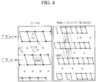
- the lithium trap structure is a structure in which lithium ions are disposed in tetrahedral sites at the time of charge, in a lattice configured by oxygen atoms of the first MO layer and the second MO layer adjacent to each other, and in this case, a repulsive force in a vertical direction occurs among metal cations of the second MO layer, lithium ions of the tetrahedral site, and a dopant of the first MO layer, so as to function as a kind of stopper when the MO layer slides in a horizontal direction, thereby suppressing the structural change.
- the lithium dumbbell structure is a structure in which lithium ions between the first MO layer and the second MO layer are in a tetrahedral site at the time of charge, and dopants between the second MO layer and the third MO layer are in the tetrahedral site, wherein the lithium ions and the dopant are symmetrically positioned on a center of the second MO layer in a lattice configured by oxygen atoms of the mutually adjacent first MO layer, second MO layer, and third MO layer, and a repulsive force occurs in a vertical direction among the lithium ions at the tetrahedral site between the first MO layer and the second MO layer, the metal cations of the second MO layer, and the dopants at the tetrahedral side between the second MO layer and the third MO layer, so as to function as a kind of a stopper when the MO layer is slid in a horizontal direction, thereby suppressing the structure change.
- FIGS. 4 and 5 For understanding the structures, schematic views thereof are shown in FIGS. 4 and 5 .
- the lithium cobalt oxide has a crystalline structure in which a MO layer commonly including a metal and oxygen and a reversible lithium layer in which lithium ions reversibly move at the time of charge and discharge are repeatedly stacked.
- the lithium ions of the lithium layer and the Co ions of the MO layers are disposed in a diagonal line in a region including no dopant, so there is no increase of the internal energy, but in a region including the dopant and forming the lithium trap structure, the lithium ions of the lithium layer, Co ions of the second MO layer, and dopant of the first MO layer are all disposed in a straight line to generate a repulsive force among them, so accompanying the internal energy increase to maintain the structure, and thereby the sliding is prevented by the characteristics that a material is to exist in the most stable state which has the lowest internal energy.
- the lithium dumbbell structure shown in a right view of FIG. 4 has the same fundamental forming protocol as in the lithium trap structure, but lithium ions between the first MO layer and the second MO layer and dopants between the second MO layer and the third MO layer move to tetrahedral sites, meaning a structure in which the lithium ions and the dopants are symmetrically disposed to each other in the center of the second MO layer.
- FIG. 1 In this case, in order to clearly describe the tetrahedral site and the octahedral site, the schematic view thereof is shown in FIG. 1 .
- the tetrahedral site (hole) refers to a space formed in a center of an atom cluster when a single atom is contacted with three atoms of an atomic layer disposed below the same, so two tetrahedral sites exist per atom when atoms having the same size are positioned as near as possible
- the octahedral site (hole) refers to a space formed in a cluster of six atoms for an octahedron which is formed when each of three atoms for two pairs of triangles contact with an alignment angle of 60 degree, wherein the space is larger than the tetrahedral site, and one octahedral site is present per atom when the atoms having the same size are disposed as near as possible.
- both the lithium dumbbell structure and the lithium trap structure may suppress the structural change by generating the repulsive force among the metal cations, dopants, and lithium ions in a vertical direction, but in a case of the lithium dumbbell structure, a trap structure is formed not only between the first MO layer and the second MO layer but also between the second MO layer and the third MO layer, unlike the lithium trap structure, so it is more preferably since it provides much better structural stability effects than the lithium trap structure generating the repulsive force between first MO layer and the second MO layer.
- the dopant which may form the lithium trap or the lithium dumbbell structure may be included at 0.001 to 1 wt% based on the cobalt amount of the lithium cobalt oxide particle, more particularly, the dopant amount may be included at 0.01 wt% to 0.3 wt%, specifically, 0.02 wt% to 0.2 wt%, and more specifically, 0.02 wt% to 0.1 wt%, to provide an active material with excellent capacity and energy by improving the sufficiently high voltage stability and also maintaining the high Co amount.
- the ratio of the dopant in the positive active material particle is too low to obtain the described structure, so the effect of improving the structural stability of the active material is almost nothing, and on the other hand, when is greater than 1 wt%, the ratio of the dopant in the positive active material particle is excessively high, even causing deterioration of the lithium transfer, so it has problems in that the output characteristic is deteriorated, and the overall capacity of the positive active material is relatively decreased.
- the lithium trap structure and the lithium dumbbell structure may be formed differently depending upon a kind of a predetermined dopant.
- the dopant includes at least one selected from Mg, Nb, Zr, and V, and may form a lithium trap and a lithium dumbbell structure.
- the dopant includes at least one selected from Mg, Nb, Zr, Ti, Mo, and V, and may form a lithium trap structure.
- the lithium cobalt oxide particle according to the present invention in order to further improve the structural stability of the lithium cobalt oxide, it is more preferable for the lithium cobalt oxide particle according to the present invention to include at least one selected from a group consisting of Mg, Nb, Zr, and V as a dopant, and more specifically, the dopant may be Mg and/or Zr.
- the dopant concentration of an outer bulk of a particle surface to 0.9*r may be relatively higher than the dopant concentration of an inner bulk from 0.9*r to a particle center.
- the positive active material according to the present invention may include Mg as a dopant included in the lithium cobalt oxide particle, and the Mg concentration of the outer bulk may be relatively higher than the Mg concentration in the inner bulk.
- the positive active material according to the present invention may include Mg and Zr as the dopant included in the lithium cobalt oxide particle, where Zr is primarily included in the outer bulk, and Mg is mostly included in the inner bulk, and the Zr concentration of the outer bulk is relatively higher than the Mg concentration of the inner bulk.
- the positive active material for a secondary battery according to the present invention is prepared by the following method, when the dopant concentration of the outer bulk of the particle surface of the lithium cobalt oxide to 0.9*r is formed relatively higher than the dopant concentration of the inner bulk of 0.9*r to the particle center, an appropriate ratio of the dopants included in the outer bulk and the inner bulk may effectively prevent the sliding phenomenon of the MO layers on the surface even under the charge condition of greater than or equal to 4.5 V, thereby further improving stability of the positive active material.
- the surface should be strengthened to prevent a phase transition, and it is therefore necessary to set the dopant concentration in the inner bulk to be higher than the dopant concentration of the outer bulk.
- the medium particle size (D50) is too small, it is not preferable since it is difficult to fabricate a particle, and the crystalline structure according to the present invention may be incomplete, and on the other hand, when it is too large, it undesirably has a poor compression density of the electrode including particles.
- the lithium cobalt oxide particle according to the present invention may have a medium particle size (D50) of 5 micrometers to 25 micrometers, particularly, 10 micrometers to 25 micrometers, and more particularly, 15 micrometers to 20 micrometers.
- D50 medium particle size
- It may further include at least one selected from a group consisting of Ca, Al, Sb, Si, and Zn, and more particularly, at least one metal selected from a group consisting of Ca, Al, and Sb, in order to stabilize the crystalline structure, in addition to the dopant.
- the lithium cobalt oxide particle may be further coated by protective chemicals, wherein the protective chemicals may be at least one of a metal, an oxide, a phosphate, and a fluoride, and the metal may be at least one of Mg, Nb, Zr, Ti, Mo, V, Zn, Si, and Al.
- the protective chemicals may be at least one of a metal, an oxide, a phosphate, and a fluoride
- the metal may be at least one of Mg, Nb, Zr, Ti, Mo, V, Zn, Si, and Al.
- the protective chemicals may be coated on a lithium cobalt oxide particle using solution reaction, mechanical grinding, solid reaction, and the like, and may reduce a speed of reacting an electrolyte in the separator with the lithium cobalt oxide particle during the charge and discharge of a battery cell, so as to suppress expansion or capacity loss caused by the reaction of the positive electrode active coating.
- the amount of the protective chemical coated on the lithium cobalt oxide particle may be 0.02 wt% to 0.8 wt%, and the thickness may be 30 nm to 250 nm.
- the thickness may be 30 nm to 250 nm.
- the lithium cobalt oxide particle according to the present invention has excellent chemical stability when the amount of the protective chemicals is 0.02 wt% to 0.6 wt%, particularly, 0.03 wt% to 0.4 wt%, and more particularly, 0.04 wt% to 0.1 wt%.
- the protective chemicals have a thickness of 30 nm to 200 nm, particularly, 30 nm to 185 nm, and more particularly, 30 nm to 150 nm, desirable output characteristics are confirmed.
- the present invention provides a method of preparing a positive active material for a secondary battery, and the method includes:
- the lithium cobalt oxide particle according to the present invention may be obtained through two sequentially performed doping processes, and specifically, the lithium cobalt oxide particle according to the present invention may be obtained by processes of mixing an appropriate amount of the first doping precursor in the precursor state and firing the same to provide a lithium cobalt-based oxide particle substituted with a dopant, coating a salt including an appropriate amount of the dopant on a surface of the first doping particle to coat a second doping precursor on the surface of the first doping particle, and then heat treating the same to provide a second doping particle.
- the method includes mixing a cobalt precursor with a lithium precursor and a doping precursor under an air atmosphere and primarily firing the same, and then coating a second doping precursor and secondarily firing the same to synthesize a lithium cobalt oxide particle, so it may maintain a higher dopant concentration on the surface compared to the case of mixing the cobalt precursor, the lithium precursor, and the doping precursor and firing the same only one time to synthesize a lithium cobalt oxide particle, and it may be synthesized in a state in which dopants are uniformly dispersed even to the inside of the particle compared to the case of synthesizing a undoped lithium cobalt oxide particle and then coating the doping precursor and firing the same, so it is more preferable in a view of imparting the desirable effects.
- the cobalt precursor is a cobalt oxide
- the kind of the cobalt oxide used in the method according to the present invention is not limited, but particularly, may be at least one selected from the group consisting of Co 3 O 4 , CoCO 3 , Co(NO 3 ) 2 , and Co(OH) 2 .
- the lithium precursor is not limited as long as the compound includes a lithium source, particularly, at least one selected from the group consisting of Li 2 CO 3 , LiOH, LiNO 3 , CH 3 COOLi, and Li 2 (COO) 2 .
- the doping precursor may be at least one selected from the group consisting of a metal, a metal oxide, or a metal salt for the dopants, and the first doping precursor and the second doping precursor are composed of a metal, a metal oxide, or a metal salt including at least one independently selected from the group consisting of Mg, Nb, Zr, Ti, Mo, and V.
- the first doping precursor and the second doping precursor may be the same or different.
- the first doping precursor when the first doping precursor is the same as the second doping precursor, it may show excellent results in both views of the inside doping effect and the surface doping effect.
- the first doping particle when the first doping particle particularly enhances the structural safety, the second doping particle including the same elements as in the first doping particle may also provide excellent surface safety. Thus it is more preferable than the case of including different dopants.
- an amount of the dopant doped from the second doping precursor may be greater than or equal to the amount of the dopant doped from the first doping precursor.
- the first doping particle generated from the first doping precursor is mainly disposed in the inner bulk of 0.9*r to the particle center
- the second doping particle generated from the second doping precursor is generally disposed in the outer bulk of the particle surface to 0.9*r, so it may be formed so that the dopant concentration of the outer bulk of the lithium cobalt oxide is relatively higher than the dopant concentration of the inner bulk.
- the surface of the lithium cobalt oxide particle As the structural change of the layered positive electrode material such as a lithium cobalt oxide at a high voltage of greater than or equal to 4.5 V occurs from the surface, the surface of the lithium cobalt oxide particle, which is the outer bulk, is formed at a higher concentration than the inner bulk to more strongly suppress the structural change of the surface, thereby providing effects of further improving the stability.
- the firing of the process (a) may be performed at 900 °C to 1100 °C for 8 hours to 12 hours, and the heat treatment of the process (c) may be performed at 700 °C to 900 °C for 1 hour to 6 hours.
- the process (a) and the process (c) are performed out of the ranges, for example, performed at an excessively low temperature or for an excessively short time, the inside structure and the surface structure of the positive active material particle are unstably formed and unfavorably doped, and on the other hand, when the process (a) and the process (c) are performed out of the ranges, for example, performed at an excessively high temperature or for an excessively long time, the physical and chemical characteristics of the lithium cobalt-based oxide for the positive active material particle are changed, even unfavorably causing performance deterioration.
- the present invention provides a positive electrode manufactured by coating a slurry including the positive active material for a secondary battery, a conductive material, and a binder on a current collector.
- the positive electrode may be manufactured by, for example, coating a positive electrode mixture including the positive active material, a conductive material, and a binder, on a positive electrode current collector, and drying it, and if required, the positive electrode mixture may further include a filler.
- the positive electrode current collector is generally made at a thickness of 3 to 500 ⁇ m, but this is not particularly limited as long as it does not cause a chemical change in the battery and has high conductivity, and for example, one selected from stainless steel, aluminum, nickel, titanium, and aluminum, or stainless steel of which the surface is treated with carbon, nickel, titanium, or silver, may be used, and specifically, aluminum may be used.
- the current collector may have fine irregularities formed on a surface thereof to increase adhesive force of the cathode active material, and various forms such as a film, a sheet, a foil, a net, a porous body, foam, a non-woven fabric body, and the like, are possibly used.
- the conductive material is generally added in an amount of 1 to 30 wt% based on the total weight of the mixture including the positive active material.
- a conductive material is not particularly limited as long as it has conductivity without causing a chemical change in the battery, and examples thereof may include: graphite such as natural graphite and artificial graphite; carbon black such as carbon black, acetylene black, Ketjen black, channel black, furnace black, lamp black, and summer black; conductive fibers such as carbon fiber and metal fiber; metal powders such as carbon fluoride, aluminum, and nickel powder; conductive whiskers such as zinc oxide and potassium titanate; conductive metal oxides such as titanium oxide; conductive materials such as polyphenylene derivatives; and the like.
- the binder included in the positive electrode is a component that assists in bonding between the active material and the conductive material and bonding to the current collector, and is generally added in an amount of 1 to 30 wt% based on the total weight of the mixture including the cathode active material.
- binder examples include polyvinylidene fluoride, polyvinyl alcohol, carboxylmethyl cellulose (CMC), starch, hydroxypropyl cellulose, regenerated cellulose, polyvinylpyrrolidone, tetrafluoroethylene, polyethylene, polypropylene, an ethylene-propylene-diene terpolymer (EPDM), sulfonated EPDM, styrenebutadiene rubber, a fluorine rubber, various copolymers, and the like.
- CMC carboxylmethyl cellulose
- EPDM ethylene-propylene-diene terpolymer
- EPDM ethylene-propylene-diene terpolymer
- EPDM ethylene-propylene-diene terpolymer
- sulfonated EPDM styrenebutadiene rubber
- fluorine rubber various copolymers, and the like.
- the present invention also provides a secondary battery characterized by including the positive electrode and the negative electrode, and an electrolyte solution.
- the secondary battery is not particularly limited, but specific examples thereof include a rechargeable lithium battery such as a lithium ion battery and a lithium ion polymer battery having advantages such as high energy density, discharge voltage, and output stability.
- the rechargeable lithium battery includes a positive electrode, a negative electrode, a separator, and a lithium salt-containing non-aqueous electrolyte solution.
- the negative electrode is manufactured by coating and drying the negative active material on the negative current collector, and optionally, may further include components as described above as needed.
- the negative current collector is generally made in a thickness of 3 to 500 micrometers.
- a negative current collector is not particularly limited as long as it has conductivity without causing a chemical change in the battery, and for example, copper, stainless steel, aluminum, nickel, titanium, fired carbon, or copper, or stainless steel of which the surface is treated with carbon, nickel, titanium, silver, and the like, an aluminum-cadmium alloy, or the like, may be used.
- the binding force of the negative active material may be strengthened by forming fine irregularities on the surface thereof, and various forms such as a film, a sheet, a foil, nets, a porous body, foam, and a non-woven fabric body may be used.
- the negative active material may include, for example: carbon such as hard carbon and graphite-based carbon; a metal composite oxide such as Li x Fe 2 O 3 (0 ⁇ x ⁇ 1), Li x WO 2 (0 ⁇ x ⁇ 1), and Sn x Me 1-x Me' y O z (Me: Mn, Fe, Pb, Ge; Me': Al, B, P, Si, Groups 1, 2, and 3 elements of the periodic table, a halogen; 0 ⁇ x ⁇ 1; 1 ⁇ y ⁇ 3; 1 ⁇ z ⁇ 8); a lithium metal; a lithium alloy; a silicon-based alloy; tin-based alloy; metal oxides such as SnO, SnO 2 , PbO, PbO 2 , Pb 2 O 3 , Pb 3 O 4 , Sb 2 O 3 , Sb 2 O 4 , Sb 2 O 5 , GeO, GeO 2 , Bi 2 O 3 , Bi 2 O 4 , and Bi 2 O 5 ; a conductive polymer such as polyacet
- the separator is interposed between the positive electrode and the negative electrode, and an insulating thin film having high ion permeability and mechanical strength is used.
- the separator has a pore diameter of generally 0.01 to 10 ⁇ m, and a thickness of 5 to 300 ⁇ m.
- an olefin-based polymer such as polypropylene, which is chemically resistant and hydrophobic, or the like, or a sheet or a nonwoven fabric formed of a glass fiber, polyethylene, or the like, is used.
- a solid electrolyte such as a polymer is used as the electrolyte
- the solid electrolyte may also serve as the separator.
- the lithium salt-containing non-aqueous electrolyte solution is composed of a non-aqueous electrolyte solution and a lithium salt.
- the non-aqueous electrolyte solution may include a non-aqueous organic solvent, an organic solid electrolyte, an inorganic solid electrolyte, and the like, but is not limited thereto.
- the non-aqueous organic solvent may include, for example, aprotic organic solvents such as N-methyl-2-pyrrolidinone, propylene carbonate, ethylene carbonate, butylene carbonate, dimethyl carbonate, diethyl carbonate, ⁇ -butyrolactone, 1,2-dimethoxy ethane, tetrahydroxy Franc, 2-methyl tetrahydrofuran, dimethyl sulfoxide, 1,3-dioxolane, formamide, dimethylformamide, dioxolane, acetonitrile, nitromethane, methyl formate, methyl acetate, phosphate triester, trimethoxy methane, dioxolane derivative, sulfolane, methyl sulfolane, 1,3-dimethyl-2-imidazolidinone, a propylene carbonate derivative, a tetrahydrofuran derivative, ether, methyl propionate, and ethyl propionate.
- the organic solid electrolyte may include, for example, polyethylene derivatives, polyethylene oxide derivatives, polypropylene oxide derivatives, phosphate ester polymers, poly agitation lysine, polyester sulfide, polyvinyl alcohol, polyfluorovinylidene, polymers including an ionic dissociation group, and the like.
- the inorganic solid electrolyte may include, for example, nitrides, halides, sulfates, or the like of Li such as Li 3 N, LiI, Li 5 NI 2 , Li 3 N-LiI-LiOH, LiSiO 4 , LiSiO 4 -LiI-LiOH, Li 2 SiS 3 , Li 4 SiO 4 , Li 4 SiO 4 -LiI-LiOH, Li 3 PO 4 -Li 2 S-SiS 2 , and the like.
- Li such as Li 3 N, LiI, Li 5 NI 2 , Li 3 N-LiI-LiOH, LiSiO 4 , LiSiO 4 -LiI-LiOH, Li 2 SiS 3 , Li 4 SiO 4 , Li 4 SiO 4 -LiI-LiOH, Li 3 PO 4 -Li 2 S-SiS 2 , and the like.
- the lithium salt is a material which is readily soluble in the non-aqueous electrolyte, and for example, LiCl, LiBr, LiI, LiClO 4 , LiBF 4 , LiB 10 Cl 10 , LiPF 6 , LiCF 3 SO 3 , LiCF 3 CO 2 , LiAsF 6 , LiSbF 6 , LiAlCl 4 , CH 3 SO 3 Li, CF 3 SO 3 Li, (CF 3 SO 2 ) 2 NLi, lithium chloroborane, lower aliphatic lithium carbonates, 4 phenyl lithium borate, imides, and the like may be used.
- non-aqueous electrolyte solution for the purpose of improving charge and discharge characteristics, flame retardancy and the like, for example, pyridine, triethylphosphite, triethanolamine, cyclic ether, ethylene diamine, n-glyme, triamide hexaphosphate, nitrobenzene derivatives, sulfur, quinone imine dyes, N-substituted oxazolidinone, N,N-substituted imidazolidine, ethylene glycol dialkyl ether, ammonium salts, pyrrole, 2-methoxy ethanol, aluminum trichloride, and the like may be added.
- pyridine triethylphosphite
- triethanolamine cyclic ether
- nitrobenzene derivatives sulfur
- quinone imine dyes N-substituted oxazolidinone
- a halogen-containing solvent such as carbon tetrachloride and ethylene trifluoride may be further included, and for improving high temperature storage characteristics, carbon dioxide gas may be further included, and FEC (fluoro-ethylene carbonate), PRS (propene sultone), and the like may be further included.
- the present invention provides a battery pack including the secondary battery and a device including the battery pack, wherein the battery pack and the device are known in the art, so the detailed descriptions are omitted in the present specification.
- the device may be, for example, a laptop computer, a netbook, a tablet PC, a mobile phone, an MP3, a wearable electronic device, a power tool, an electric vehicle (EV), a hybrid electric vehicle (HEV), a plug-in hybrid electric vehicle (PHEV), an electric bicycle (E-bike), an electric scooter (E-scooter), an electric golf cart, or a system for electric power storage, but is not limited thereto.
- a laptop computer a netbook, a tablet PC, a mobile phone, an MP3, a wearable electronic device, a power tool, an electric vehicle (EV), a hybrid electric vehicle (HEV), a plug-in hybrid electric vehicle (PHEV), an electric bicycle (E-bike), an electric scooter (E-scooter), an electric golf cart, or a system for electric power storage, but is not limited thereto.
- EV electric vehicle
- HEV hybrid electric vehicle
- PHEV plug-in hybrid electric vehicle
- E-bike electric bicycle
- E-scooter electric scooter
- a lithium cobalt oxide was obtained in accordance with the same procedure as in Preparation Example 2, except that Mg (Mg source: MgO) was used as a dopant instead of the Al in Preparation Example 2.
- a lithium cobalt oxide was obtained in accordance with the same procedure as in Preparation Example 2, except that Ti (Ti source: TiO 2 ) was used as a dopant instead of the Al in Preparation Example 2.
- a lithium cobalt oxide was obtained in accordance with the same procedure as in Preparation Example 2, except that Zr (Zr source: ZrO 2 ) was used as a dopant instead of the Al in Preparation Example 2.
- a lithium cobalt oxide was obtained in accordance with the same procedure as in Preparation Example 2, except that Nb (Nb source: Nb 2 O 5 ) was used as a dopant instead of the Al in Preparation Example 2.
- a lithium cobalt oxide was obtained in accordance with the same procedure as in Preparation Example 2, except that Ta (Ta source: Ta 2 O 5 ) was used as a dopant instead of the Al in Preparation Example 2.
- a lithium cobalt oxide was obtained in accordance with the same procedure as in Preparation Example 2, except that Mo (Mo source: MoO 3 ) was used as a dopant instead of the Al in Preparation Example 2.
- a lithium cobalt oxide was obtained in accordance with the same procedure as in Preparation Example 2, except that W (W source: WO 3 ) was used as a dopant instead of the Al in Preparation Example 2.
- a lithium cobalt oxide was obtained in accordance with the same procedure as in Preparation Example 2, except that V (V source: V 2 O 5 ) was used as a dopant instead of the Al in Preparation Example 2.
- a lithium cobalt oxide was obtained in accordance with the same procedure as in Preparation Example 2, except that Mn (Mn source: MnO 2 ) was used as a dopant instead of the Al in Preparation Example 2.
- the lithium cobalt oxides obtained from Preparation Examples 1 to 11 were used as a positive active material, PVdF was used as a binder, and natural graphite was used as a conductive material.
- the positive active material: the binder: the conductive material were mixed at a weight ratio of 96:2:2 into NMP and then coated on an Al foil having a thickness of 20 ⁇ m and dried at 130 °C to provide a positive electrode.
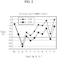
- the generated energy is a negative value, so the lithium dumbbell structure is spontaneously formed under a high voltage of 4.6 V.
- the generated energy is a negative value, so it is understood that the lithium trap structure is spontaneously formed under a high voltage of 4.6 V.
- Mg, Zr, Nb, or V among dopants have a negative value of the generated energy of the lithium trap structure and the dumbbell structure under the high voltage of 4.6 V.
- Mg and Zr have the greatest negative value in the lithium dumbbell structure and the lithium trap structure, respectively, so it is understood that they are the most preferable elements for providing the structures.
- the structure generation energy is calculated using VASP (Vienna Ab initio Simulation Program), the DFT functional uses PBE, and the Pseudo-potential uses PAW-PBE.
- the cut-off energy is calculated at 500 eV.
- a salt including 600 ppm of Zr, which was 15 times (0.06 wt%) the doped Mg amount was dry-mixed with lithium cobalt oxide particles and coated, and secondarily fired in a furnace at 800 °C for 4 hours to provide a positive active material in which Zr was doped on the outer bulk at a concentration of 600 ppm.
- a salt including 400 ppm of Mg which was 0.66 times (0.04 wt%) the doped Mg amount, was dry-mixed with lithium cobalt oxide particles and coated, and then subjected to secondary firing in a furnace at 800 °C for 4 hours to provide a positive active material in which Mg was doped in the outer bulk at a concentration of 400 ppm.
- a salt including 600 ppm of Mg, which was 1.5 times (0.06 wt%) the doped Mg amount was dry-mixed with lithium cobalt oxide particles and coated, and then subjected to secondary firing in a furnace at 800 °C for 4 hours to provide a positive active material in which Mg was doped in the outer bulk at a concentration of 400 ppm.
- the lithium cobalt oxide obtained from Preparation Example 3 was used as a positive active material.
- Each positive active material particle obtained from Examples 1 and 2 and Comparative Example 1, a binder of PVdF, and a conductive material of natural graphite were used.
- the positive active material: the binder: the conductive material were well mixed into NMP to provide a weight ratio of 96:2:2 and coated on an Al foil having a thickness of 20 ⁇ m and then dried at 130 °C to provide a positive electrode.
- Examples 1 to 4 maintained high performance with capacity retention of greater than or equal to 90 % even after 30 cycles and even under a high voltage condition of 4.5 V, compared to the case of using the undoped lithium cobalt oxide according to Comparative Example 1.
- the dopants included in the outer bulk of the lithium cobalt oxide particle suppressed the crystal structure collapse from the external surface, and the dopants included in the inner bulk suppressed a side reaction between the electrolyte solution and Co 4+ ions present on the particle surface in a state of discharging lithium ions, so as to stably maintain the crystal structure.
- the surface stability may be further enhanced under the charge condition of greater than or equal to 4.5 V, compared to the cases of Examples 2 and 3, so it is confirmed that it has much better capacity retention of greater than or equal to 95 % after the 30 cycles.
- the positive active material particle according to the present invention includes a predetermined element as a dopant, and has a crystalline structure in which metal oxide layers (MO layers) including metals and oxygen and reversible lithium layers are repeatedly stacked, and the dopant and/or lithium ions move from octahedral sites to tetrahedral sites at the time of charge, thereby forming a lithium trap and/or a lithium dumbbell structure, thereby providing effects of suppressing the structural change on the particle surface to improve the cycle-life characteristics at a high temperature and also of stably maintaining the crystalline structure even when emitting a large amount of lithium ions.
- MO layers metal oxide layers
- the dopant and/or lithium ions move from octahedral sites to tetrahedral sites at the time of charge, thereby forming a lithium trap and/or a lithium dumbbell structure, thereby providing effects of suppressing the structural change on the particle surface to improve the cycle-life characteristics at a high temperature and also of
Landscapes
- Chemical & Material Sciences (AREA)
- Chemical Kinetics & Catalysis (AREA)
- Electrochemistry (AREA)
- General Chemical & Material Sciences (AREA)
- Engineering & Computer Science (AREA)
- Composite Materials (AREA)
- Inorganic Chemistry (AREA)
- Organic Chemistry (AREA)
- Manufacturing & Machinery (AREA)
- Materials Engineering (AREA)
- Battery Electrode And Active Subsutance (AREA)
- Secondary Cells (AREA)
Abstract
Description
- This application claims priority to and the benefit of Korean Patent Application No.
10-2016-0116951 - The present invention relates to a positive electrode active material for a rechargeable lithium battery including a lithium cobalt oxide for a high voltage, and a method for preparing same.
- As technology development and demand for mobile devices have increased, there has been a rapid increase in demand for secondary batteries as energy sources, and thus a rechargeable lithium battery of secondary batteries having high energy density and operation potential, a long cycle-life, and a low discharge rate has been commercially available.
- In addition, considerable research on an electric vehicle and a hybrid electric vehicle to replace a vehicle using a fossil fuel such as a gasoline vehicle, a diesel vehicle, and the like, which are regarded as primary causes of air pollution, has been undertaken, as interest in the environment has recently increased. The electric vehicle, the hybrid electric vehicle, and the like mainly have a power source of a nickel hydrogen metal secondary battery, but researches on utilizing a rechargeable lithium battery having a high energy density and discharge have been actively made, and they are entering the commercialization stage.
- Representatively, a prismatic secondary battery and a pouch secondary battery applicable to a product such as a mobile phone having a thin thickness have been highly demanded in a view of a battery shape, and a rechargeable lithium battery such as a lithium ion battery, a lithium ion polymer battery, and the like having a merit of high energy density, discharge, output stability, and the like is highly demanded in a view of a material.
- Currently, LiCoO2, a ternary system (NMC/NCA), LiMnO4, LiFePO4, and the like are being used as a positive electrode material for the rechargeable lithium battery. Among them, LiCoO2 has problems in that cobalt is expensive and it has low capacity in the same voltage compared to the ternary system, so the amount of use of the ternary system and the like has been gradually increasing to provide a secondary battery with higher capacity.
- However, LiCoO2 has been mainly used so far since it has excellent properties such as a high compression density and electrochemical characteristics such as a high cycle characteristic. At the same time, LiCoO2 has problems in that a charge and discharge current amount is low at about 150 mAh/g, and a crystalline structure at a voltage of greater than or equal to 4.3 V is unstable to decrease a cycle-life characteristic.
- Particularly, when applying a high voltage for developing a high-capacity secondary battery, a Li amount for LiCoO2 is increased, so it has problems in that the possibilities of destabilizing a surface and a structure arise to generate a gas due to a side-reaction with the electrolyte solution, so stability is deteriorated, for example, combustion or a swelling phenomenon, and cycle-life characteristics are dramatically deteriorated.
- In order to solve the problems, doping or coating a metal such as Al, Ti, Mg, or Zr on a surface of the LiCoO2 is a method that is generally used. However, even in the case of doping the metal, a phase change may be generated, and furthermore, in the case of a coating layer including the metal, it may interrupt Li ion transfer during the charge and discharge, thereby potentially causing the performance of the secondary battery to be deteriorated.
- Accordingly, it is stably oxidized/reduced only until about 4.45 V through the conventional doping/coating method, so different approaches from the conventional art are needed at greater than or equal to 4.5 V.
- Thus, there is a great need to develop a lithium cobalt oxide-based positive active material which may ensure structural stability without deteriorating performance even at a high voltage.
- The present invention aims to solve the above-described problems of the conventional art and technical problems required from the past.
- By repeating in-depth studies and various experiments, the inventors of this application confirmed that when lithium cobalt oxide particles include a certain element as a dopant, wherein in a crystalline structure in which metal oxide layers (MO layers) including metals and oxygen and reversible lithium layers are repeatedly stacked, the dopant and/or lithium ions move from octahedral sites to tetrahedral sites at the time of charge, thereby forming a lithium trap and/or a lithium dumbbell structure, which will be described later, a desirable effect is exhibited, and completed the present invention.
- The positive electrode active material for a rechargeable lithium battery including the lithium cobalt oxide particles according to the present invention includes lithium cobalt oxide particles including at least one selected from Mg, Nb, Zr, Ti, Mo, and V as a dopant;
the lithium cobalt oxide particles have a crystalline structure in which metal oxide layers (MO layers) including metals and oxygen and reversible lithium layers in which lithium ions move reversibly at the time of charge and discharge are repeatedly stacked; and
the dopant and/or lithium ions move from octahedral sites to tetrahedral sites at the time of charge in a lattice configured by oxygen atoms of the MO layers adjacent to each other, thereby forming a lithium trap and/or lithium dumbbell structure. - Generally, when the lithium cobalt oxide is used as a positive active material at a high voltage, it causes problems in that the crystal structure becomes defective while a large amount of lithium ions are released from the lithium cobalt oxide particles, such that the destabilized crystalline structure collapses to deteriorate reversibility. In addition, in a state in which the lithium ion is released, when Co3+ or Co4+ ions present on the surface of the lithium cobalt oxide particle are reduced by an electrolyte solution, oxygen is detached from the crystalline structure to accelerate the structural collapse.
- Accordingly, in order to stably use the lithium cobalt oxide under a high voltage, even if a large amount of lithium ions are emitted, the side reaction of Co ions and the electrolyte solution should be suppressed while the crystalline structure thereof is stably maintained.
- Therefore, in the present invention, the lithium cobalt oxide particles include a dopant of Mg, Nb, Zr, Ti, Mo, V, and the like in a structure in which MO layers and reversible lithium layers are repeatedly stacked, and when the dopant and/or lithium ions move from octahedral sites to tetrahedral sites at the time of charge, thereby forming a lithium trap and/or a lithium dumbbell structure, a repulsive force among metals of the MO layer, lithium ions of the tetrahedral site, and dopants occurs to suppress a phenomenon in which the MO layers relatively slide, thereby effectively preventing the structural change.
- The lithium trap structure is a structure in which lithium ions are disposed in tetrahedral sites at the time of charge, in a lattice configured by oxygen atoms of the first MO layer and the second MO layer adjacent to each other, and in this case, a repulsive force in a vertical direction occurs among metal cations of the second MO layer, lithium ions of the tetrahedral site, and a dopant of the first MO layer, so as to function as a kind of stopper when the MO layer slides in a horizontal direction, thereby suppressing the structural change.
- Similarly, the lithium dumbbell structure is a structure in which lithium ions between the first MO layer and the second MO layer are in a tetrahedral site at the time of charge, and dopants between the second MO layer and the third MO layer are in the tetrahedral site, wherein the lithium ions and the dopant are symmetrically positioned on a center of the second MO layer in a lattice configured by oxygen atoms of the mutually adjacent first MO layer, second MO layer, and third MO layer, and a repulsive force occurs in a vertical direction among the lithium ions at the tetrahedral site between the first MO layer and the second MO layer, the metal cations of the second MO layer, and the dopants at the tetrahedral side between the second MO layer and the third MO layer, so as to function as a kind of a stopper when the MO layer is slid in a horizontal direction, thereby suppressing the structure change.
- For understanding the structures, schematic views thereof are shown in
FIGS. 4 and5 . - Referring to
FIGS. 4 and5 , the lithium cobalt oxide has a crystalline structure in which a MO layer commonly including a metal and oxygen and a reversible lithium layer in which lithium ions reversibly move at the time of charge and discharge are repeatedly stacked. - First, for describing a structure of the lithium trap, referring to a left view of
FIG. 4 together withFIG. 5 , cobalt ions of a first MO layer and a second MO layer and lithium ions of a lithium layer are disposed at all octahedral sites in a lattice region including no dopant in the crystalline structure, but in the lattice region where the cobalt (Co) ions of the first MO layer are substituted with a dopant such as Mg, Zr, and the like, the crystalline structure is changed so that lithium ions of the lithium layer disposed between the first MO layer and the second MO layer and the dopant of the first MO layer move to tetrahedral sites, which is called a lithium trap structure. When obtaining the structure, when sliding in a horizontal direction in the crystalline structure of the lithium cobalt oxide, the lithium ions of the lithium layer and the Co ions of the MO layers are disposed in a diagonal line in a region including no dopant, so there is no increase of the internal energy, but in a region including the dopant and forming the lithium trap structure, the lithium ions of the lithium layer, Co ions of the second MO layer, and dopant of the first MO layer are all disposed in a straight line to generate a repulsive force among them, so accompanying the internal energy increase to maintain the structure, and thereby the sliding is prevented by the characteristics that a material is to exist in the most stable state which has the lowest internal energy. - Similarly, the lithium dumbbell structure shown in a right view of
FIG. 4 has the same fundamental forming protocol as in the lithium trap structure, but lithium ions between the first MO layer and the second MO layer and dopants between the second MO layer and the third MO layer move to tetrahedral sites, meaning a structure in which the lithium ions and the dopants are symmetrically disposed to each other in the center of the second MO layer. - In this case, in order to clearly describe the tetrahedral site and the octahedral site, the schematic view thereof is shown in
FIG. 1 . - Referring to
FIG. 1 , the tetrahedral site (hole) refers to a space formed in a center of an atom cluster when a single atom is contacted with three atoms of an atomic layer disposed below the same, so two tetrahedral sites exist per atom when atoms having the same size are positioned as near as possible, and the octahedral site (hole) refers to a space formed in a cluster of six atoms for an octahedron which is formed when each of three atoms for two pairs of triangles contact with an alignment angle of 60 degree, wherein the space is larger than the tetrahedral site, and one octahedral site is present per atom when the atoms having the same size are disposed as near as possible. - Accordingly, both the lithium dumbbell structure and the lithium trap structure may suppress the structural change by generating the repulsive force among the metal cations, dopants, and lithium ions in a vertical direction, but in a case of the lithium dumbbell structure, a trap structure is formed not only between the first MO layer and the second MO layer but also between the second MO layer and the third MO layer, unlike the lithium trap structure, so it is more preferably since it provides much better structural stability effects than the lithium trap structure generating the repulsive force between first MO layer and the second MO layer.
- The dopant which may form the lithium trap or the lithium dumbbell structure may be included at 0.001 to 1 wt% based on the cobalt amount of the lithium cobalt oxide particle, more particularly, the dopant amount may be included at 0.01 wt% to 0.3 wt%, specifically, 0.02 wt% to 0.2 wt%, and more specifically, 0.02 wt% to 0.1 wt%, to provide an active material with excellent capacity and energy by improving the sufficiently high voltage stability and also maintaining the high Co amount.
- When the amount of dopant is less than 0.001 wt% which is out of the range, the ratio of the dopant in the positive active material particle is too low to obtain the described structure, so the effect of improving the structural stability of the active material is almost nothing, and on the other hand, when is greater than 1 wt%, the ratio of the dopant in the positive active material particle is excessively high, even causing deterioration of the lithium transfer, so it has problems in that the output characteristic is deteriorated, and the overall capacity of the positive active material is relatively decreased.
- Meanwhile, the lithium trap structure and the lithium dumbbell structure may be formed differently depending upon a kind of a predetermined dopant.
- In one specific example, the dopant includes at least one selected from Mg, Nb, Zr, and V, and may form a lithium trap and a lithium dumbbell structure.
- In addition, the dopant includes at least one selected from Mg, Nb, Zr, Ti, Mo, and V, and may form a lithium trap structure.
- The forming of the structure according to a kind of the dopant as stated above is further described in detail in the following Experimental Example 1.
- From the results as stated above, in order to further improve the structural stability of the lithium cobalt oxide, it is more preferable for the lithium cobalt oxide particle according to the present invention to include at least one selected from a group consisting of Mg, Nb, Zr, and V as a dopant, and more specifically, the dopant may be Mg and/or Zr.
- Meanwhile, in the positive active material for a secondary battery cell according to the present invention, when r refers to an average radius of the lithium cobalt oxide particle, the dopant concentration of an outer bulk of a particle surface to 0.9*r may be relatively higher than the dopant concentration of an inner bulk from 0.9*r to a particle center.
- In one example, the positive active material according to the present invention may include Mg as a dopant included in the lithium cobalt oxide particle, and the Mg concentration of the outer bulk may be relatively higher than the Mg concentration in the inner bulk.
- In another example, the positive active material according to the present invention may include Mg and Zr as the dopant included in the lithium cobalt oxide particle, where Zr is primarily included in the outer bulk, and Mg is mostly included in the inner bulk, and the Zr concentration of the outer bulk is relatively higher than the Mg concentration of the inner bulk.
- Thus when the positive active material for a secondary battery according to the present invention is prepared by the following method, when the dopant concentration of the outer bulk of the particle surface of the lithium cobalt oxide to 0.9*r is formed relatively higher than the dopant concentration of the inner bulk of 0.9*r to the particle center, an appropriate ratio of the dopants included in the outer bulk and the inner bulk may effectively prevent the sliding phenomenon of the MO layers on the surface even under the charge condition of greater than or equal to 4.5 V, thereby further improving stability of the positive active material.
- At a high voltage of greater than or equal to 4.5 V, almost no Li remains on the surface of LiCoO2, so it is very easy to convert it to an O1 phase. Accordingly, the surface should be strengthened to prevent a phase transition, and it is therefore necessary to set the dopant concentration in the inner bulk to be higher than the dopant concentration of the outer bulk.
- When the medium particle size (D50) is too small, it is not preferable since it is difficult to fabricate a particle, and the crystalline structure according to the present invention may be incomplete, and on the other hand, when it is too large, it undesirably has a poor compression density of the electrode including particles.
- Accordingly, the lithium cobalt oxide particle according to the present invention may have a medium particle size (D50) of 5 micrometers to 25 micrometers, particularly, 10 micrometers to 25 micrometers, and more particularly, 15 micrometers to 20 micrometers.
- It may further include at least one selected from a group consisting of Ca, Al, Sb, Si, and Zn, and more particularly, at least one metal selected from a group consisting of Ca, Al, and Sb, in order to stabilize the crystalline structure, in addition to the dopant.
- The lithium cobalt oxide particle may be further coated by protective chemicals, wherein the protective chemicals may be at least one of a metal, an oxide, a phosphate, and a fluoride, and the metal may be at least one of Mg, Nb, Zr, Ti, Mo, V, Zn, Si, and Al.
- The protective chemicals may be coated on a lithium cobalt oxide particle using solution reaction, mechanical grinding, solid reaction, and the like, and may reduce a speed of reacting an electrolyte in the separator with the lithium cobalt oxide particle during the charge and discharge of a battery cell, so as to suppress expansion or capacity loss caused by the reaction of the positive electrode active coating.
- In this case, the amount of the protective chemical coated on the lithium cobalt oxide particle may be 0.02 wt% to 0.8 wt%, and the thickness may be 30 nm to 250 nm. When is included at less than 0.02 wt% or formed in a thickness of less than 30 nm, it may not obtain the desirable effects, and when is included at greater than 0.8 wt% or formed in a thickness of greater than 250 nm, it is not preferable since the output characteristics of the battery are deteriorated.
- According to the findings of the inventors of the present invention, it is confirmed that the lithium cobalt oxide particle according to the present invention has excellent chemical stability when the amount of the protective chemicals is 0.02 wt% to 0.6 wt%, particularly, 0.03 wt% to 0.4 wt%, and more particularly, 0.04 wt% to 0.1 wt%.
- In addition, when the protective chemicals have a thickness of 30 nm to 200 nm, particularly, 30 nm to 185 nm, and more particularly, 30 nm to 150 nm, desirable output characteristics are confirmed.
- The present invention provides a method of preparing a positive active material for a secondary battery, and the method includes:
- (a) mixing a cobalt precursor, a lithium precursor, and a first doping precursor and then firing the same to synthesize a first doping particle;
- (b) coating a second doping precursor on a surface of the first doping particle; and
- (c) heating the coated first doping particle to synthesize a second doping particle which is a lithium cobalt oxide particle.
- That is, the lithium cobalt oxide particle according to the present invention may be obtained through two sequentially performed doping processes, and specifically, the lithium cobalt oxide particle according to the present invention may be obtained by processes of mixing an appropriate amount of the first doping precursor in the precursor state and firing the same to provide a lithium cobalt-based oxide particle substituted with a dopant, coating a salt including an appropriate amount of the dopant on a surface of the first doping particle to coat a second doping precursor on the surface of the first doping particle, and then heat treating the same to provide a second doping particle.
- The method includes mixing a cobalt precursor with a lithium precursor and a doping precursor under an air atmosphere and primarily firing the same, and then coating a second doping precursor and secondarily firing the same to synthesize a lithium cobalt oxide particle, so it may maintain a higher dopant concentration on the surface compared to the case of mixing the cobalt precursor, the lithium precursor, and the doping precursor and firing the same only one time to synthesize a lithium cobalt oxide particle, and it may be synthesized in a state in which dopants are uniformly dispersed even to the inside of the particle compared to the case of synthesizing a undoped lithium cobalt oxide particle and then coating the doping precursor and firing the same, so it is more preferable in a view of imparting the desirable effects.
- Herein, the cobalt precursor is a cobalt oxide, and the kind of the cobalt oxide used in the method according to the present invention is not limited, but particularly, may be at least one selected from the group consisting of Co3O4, CoCO3, Co(NO3)2, and Co(OH)2.
- In addition, the lithium precursor is not limited as long as the compound includes a lithium source, particularly, at least one selected from the group consisting of Li2CO3, LiOH, LiNO3, CH3COOLi, and Li2(COO)2.
- The doping precursor may be at least one selected from the group consisting of a metal, a metal oxide, or a metal salt for the dopants, and the first doping precursor and the second doping precursor are composed of a metal, a metal oxide, or a metal salt including at least one independently selected from the group consisting of Mg, Nb, Zr, Ti, Mo, and V. In one specific example, the first doping precursor and the second doping precursor may be the same or different.
- But when the first doping precursor is the same as the second doping precursor, it may show excellent results in both views of the inside doping effect and the surface doping effect. In other words, when the first doping particle particularly enhances the structural safety, the second doping particle including the same elements as in the first doping particle may also provide excellent surface safety. Thus it is more preferable than the case of including different dopants.
- Meanwhile, an amount of the dopant doped from the second doping precursor may be greater than or equal to the amount of the dopant doped from the first doping precursor.
- Herein, the first doping particle generated from the first doping precursor is mainly disposed in the inner bulk of 0.9*r to the particle center, and the second doping particle generated from the second doping precursor is generally disposed in the outer bulk of the particle surface to 0.9*r, so it may be formed so that the dopant concentration of the outer bulk of the lithium cobalt oxide is relatively higher than the dopant concentration of the inner bulk.
- As the structural change of the layered positive electrode material such as a lithium cobalt oxide at a high voltage of greater than or equal to 4.5 V occurs from the surface, the surface of the lithium cobalt oxide particle, which is the outer bulk, is formed at a higher concentration than the inner bulk to more strongly suppress the structural change of the surface, thereby providing effects of further improving the stability.
- Meanwhile, the firing of the process (a) may be performed at 900 °C to 1100 °C for 8 hours to 12 hours, and the heat treatment of the process (c) may be performed at 700 °C to 900 °C for 1 hour to 6 hours.
- When the process (a) and the process (c) are performed out of the ranges, for example, performed at an excessively low temperature or for an excessively short time, the inside structure and the surface structure of the positive active material particle are unstably formed and unfavorably doped, and on the other hand, when the process (a) and the process (c) are performed out of the ranges, for example, performed at an excessively high temperature or for an excessively long time, the physical and chemical characteristics of the lithium cobalt-based oxide for the positive active material particle are changed, even unfavorably causing performance deterioration.
- The present invention provides a positive electrode manufactured by coating a slurry including the positive active material for a secondary battery, a conductive material, and a binder on a current collector.
- The positive electrode may be manufactured by, for example, coating a positive electrode mixture including the positive active material, a conductive material, and a binder, on a positive electrode current collector, and drying it, and if required, the positive electrode mixture may further include a filler.
- The positive electrode current collector is generally made at a thickness of 3 to 500 µm, but this is not particularly limited as long as it does not cause a chemical change in the battery and has high conductivity, and for example, one selected from stainless steel, aluminum, nickel, titanium, and aluminum, or stainless steel of which the surface is treated with carbon, nickel, titanium, or silver, may be used, and specifically, aluminum may be used. The current collector may have fine irregularities formed on a surface thereof to increase adhesive force of the cathode active material, and various forms such as a film, a sheet, a foil, a net, a porous body, foam, a non-woven fabric body, and the like, are possibly used.
- The positive active material may include, for example: a layered compound such as a lithium nickel oxide (LiNiO2) layered compound 1 or a compound substituted with one or more transition metals; a lithium manganese oxide such as one of a chemical formula Li1+xMn2-xO4 (wherein x is 0 to 0.33), LiMnO3, LiMn2O3, LiMnO2, and the like; a lithium copper oxide (Li2CuO2); a vanadium oxide such as LiV3O8, LiV3O4, V2O5, Cu2V2O7, and the like; a Ni site-type lithium nickel oxide represented by a chemical formula LiNi1-xMxO2 (wherein M = Co, Mn, Al, Cu, Fe, Mg, B, or Ga, and x = 0.01 to 0.3); a lithium manganese composite oxide represented by a chemical formula LiMn2-xMxO2 (wherein M = Co, Ni, Fe, Cr, Zn, or Ta, and x = 0.01 to 0.1) or Li2Mn3MO8 (wherein M = Fe, Co, Ni, Cu, or Zn); LiMn2O4 in which a part of Li in the chemical formula is substituted with an alkaline earth metal ion; a disulfide compound; Fe2(MoO4)3; and the like, in addition to the lithium cobalt oxide particle, but is not limited thereto.
- The conductive material is generally added in an amount of 1 to 30 wt% based on the total weight of the mixture including the positive active material. Such a conductive material is not particularly limited as long as it has conductivity without causing a chemical change in the battery, and examples thereof may include: graphite such as natural graphite and artificial graphite; carbon black such as carbon black, acetylene black, Ketjen black, channel black, furnace black, lamp black, and summer black; conductive fibers such as carbon fiber and metal fiber; metal powders such as carbon fluoride, aluminum, and nickel powder; conductive whiskers such as zinc oxide and potassium titanate; conductive metal oxides such as titanium oxide; conductive materials such as polyphenylene derivatives; and the like.
- The binder included in the positive electrode is a component that assists in bonding between the active material and the conductive material and bonding to the current collector, and is generally added in an amount of 1 to 30 wt% based on the total weight of the mixture including the cathode active material. Examples of the binder may include polyvinylidene fluoride, polyvinyl alcohol, carboxylmethyl cellulose (CMC), starch, hydroxypropyl cellulose, regenerated cellulose, polyvinylpyrrolidone, tetrafluoroethylene, polyethylene, polypropylene, an ethylene-propylene-diene terpolymer (EPDM), sulfonated EPDM, styrenebutadiene rubber, a fluorine rubber, various copolymers, and the like.
- The present invention also provides a secondary battery characterized by including the positive electrode and the negative electrode, and an electrolyte solution. The secondary battery is not particularly limited, but specific examples thereof include a rechargeable lithium battery such as a lithium ion battery and a lithium ion polymer battery having advantages such as high energy density, discharge voltage, and output stability.
- Generally, the rechargeable lithium battery includes a positive electrode, a negative electrode, a separator, and a lithium salt-containing non-aqueous electrolyte solution.
- Hereinafter, other aspects of the rechargeable lithium battery are described.
- The negative electrode is manufactured by coating and drying the negative active material on the negative current collector, and optionally, may further include components as described above as needed.
- The negative current collector is generally made in a thickness of 3 to 500 micrometers. Such a negative current collector is not particularly limited as long as it has conductivity without causing a chemical change in the battery, and for example, copper, stainless steel, aluminum, nickel, titanium, fired carbon, or copper, or stainless steel of which the surface is treated with carbon, nickel, titanium, silver, and the like, an aluminum-cadmium alloy, or the like, may be used. Further, like the positive electrode current collector, the binding force of the negative active material may be strengthened by forming fine irregularities on the surface thereof, and various forms such as a film, a sheet, a foil, nets, a porous body, foam, and a non-woven fabric body may be used.
- The negative active material may include, for example: carbon such as hard carbon and graphite-based carbon; a metal composite oxide such as LixFe2O3 (0≤x≤1), LixWO2 (0≤x≤1), and SnxMe1-xMe'yOz (Me: Mn, Fe, Pb, Ge; Me': Al, B, P, Si, Groups 1, 2, and 3 elements of the periodic table, a halogen; 0≤x≤1; 1≤y≤3; 1≤z≤8); a lithium metal; a lithium alloy; a silicon-based alloy; tin-based alloy; metal oxides such as SnO, SnO2, PbO, PbO2, Pb2O3, Pb3O4, Sb2O3, Sb2O4, Sb2O5, GeO, GeO2, Bi2O3, Bi2O4, and Bi2O5; a conductive polymer such as polyacetylene; Li-Co-Ni-based materials; and the like.
- The separator is interposed between the positive electrode and the negative electrode, and an insulating thin film having high ion permeability and mechanical strength is used. The separator has a pore diameter of generally 0.01 to 10 µm, and a thickness of 5 to 300 µm. For the separator, for example, an olefin-based polymer such as polypropylene, which is chemically resistant and hydrophobic, or the like, or a sheet or a nonwoven fabric formed of a glass fiber, polyethylene, or the like, is used. In the case that a solid electrolyte such as a polymer is used as the electrolyte, the solid electrolyte may also serve as the separator.
- The lithium salt-containing non-aqueous electrolyte solution is composed of a non-aqueous electrolyte solution and a lithium salt. The non-aqueous electrolyte solution may include a non-aqueous organic solvent, an organic solid electrolyte, an inorganic solid electrolyte, and the like, but is not limited thereto.
- The non-aqueous organic solvent may include, for example, aprotic organic solvents such as N-methyl-2-pyrrolidinone, propylene carbonate, ethylene carbonate, butylene carbonate, dimethyl carbonate, diethyl carbonate, γ-butyrolactone, 1,2-dimethoxy ethane, tetrahydroxy Franc, 2-methyl tetrahydrofuran, dimethyl sulfoxide, 1,3-dioxolane, formamide, dimethylformamide, dioxolane, acetonitrile, nitromethane, methyl formate, methyl acetate, phosphate triester, trimethoxy methane, dioxolane derivative, sulfolane, methyl sulfolane, 1,3-dimethyl-2-imidazolidinone, a propylene carbonate derivative, a tetrahydrofuran derivative, ether, methyl propionate, and ethyl propionate.
- The organic solid electrolyte may include, for example, polyethylene derivatives, polyethylene oxide derivatives, polypropylene oxide derivatives, phosphate ester polymers, poly agitation lysine, polyester sulfide, polyvinyl alcohol, polyfluorovinylidene, polymers including an ionic dissociation group, and the like.
- The inorganic solid electrolyte may include, for example, nitrides, halides, sulfates, or the like of Li such as Li3N, LiI, Li5NI2, Li3N-LiI-LiOH, LiSiO4, LiSiO4-LiI-LiOH, Li2SiS3, Li4SiO4, Li4SiO4-LiI-LiOH, Li3PO4-Li2S-SiS2, and the like.
- The lithium salt is a material which is readily soluble in the non-aqueous electrolyte, and for example, LiCl, LiBr, LiI, LiClO4, LiBF4, LiB10Cl10, LiPF6, LiCF3SO3, LiCF3CO2, LiAsF6, LiSbF6, LiAlCl4, CH3SO3Li, CF3SO3Li, (CF3SO2)2NLi, lithium chloroborane, lower aliphatic lithium carbonates, 4 phenyl lithium borate, imides, and the like may be used.
- Further, to the non-aqueous electrolyte solution, for the purpose of improving charge and discharge characteristics, flame retardancy and the like, for example, pyridine, triethylphosphite, triethanolamine, cyclic ether, ethylene diamine, n-glyme, triamide hexaphosphate, nitrobenzene derivatives, sulfur, quinone imine dyes, N-substituted oxazolidinone, N,N-substituted imidazolidine, ethylene glycol dialkyl ether, ammonium salts, pyrrole, 2-methoxy ethanol, aluminum trichloride, and the like may be added. In some cases, for imparting incombustibility, a halogen-containing solvent such as carbon tetrachloride and ethylene trifluoride may be further included, and for improving high temperature storage characteristics, carbon dioxide gas may be further included, and FEC (fluoro-ethylene carbonate), PRS (propene sultone), and the like may be further included.
- The present invention provides a battery pack including the secondary battery and a device including the battery pack, wherein the battery pack and the device are known in the art, so the detailed descriptions are omitted in the present specification.
- The device may be, for example, a laptop computer, a netbook, a tablet PC, a mobile phone, an MP3, a wearable electronic device, a power tool, an electric vehicle (EV), a hybrid electric vehicle (HEV), a plug-in hybrid electric vehicle (PHEV), an electric bicycle (E-bike), an electric scooter (E-scooter), an electric golf cart, or a system for electric power storage, but is not limited thereto.
-
-
FIG. 1 is a schematic view showing an octahedral site or a tetrahedral site where a dopant or a lithium ion is disposed. -
FIG. 2 is a graph showing generated energy of a lithium dumbbell structure according to Experimental Example 1 of the present invention. -
FIG. 3 is a graph showing generated energy of a lithium trap structure according to Experimental Example 1 of the present invention. -
FIG. 4 is a schematic view showing a lithium dumbbell and a lithium trap structure according to an embodiment of the present invention. -
FIG. 5 is a side-sectional view of a dopant or a lithium ion in an octahedral site or a tetrahedral site according to an embodiment of the present invention. -
FIG. 6 is a graph showing capacity retention of each battery of Examples 1 and 2 according to experimental examples of the present invention and a comparative example depending upon a cycle number. - Hereinafter, exemplary embodiments of the present invention will be described referring to drawings, but this is for easier understanding of the present invention, and the scope of the present invention is not limited thereto.
- 8.19 g of Co3O4 and 3.74 g of Li2CO3 were mixed and then fired in a furnace at 1000 °C for 10 hours to provide a lithium cobalt oxide.
- 8.19 g of Co3O4, 3.74 g of Li2CO3, and 1000 ppm of Al (Al source: Al2O3) were mixed and then fired in a furnace at 1000 °C for 10 hours to provide a lithium cobalt oxide in which Al of the lithium cobalt oxide was doped.
- A lithium cobalt oxide was obtained in accordance with the same procedure as in Preparation Example 2, except that Mg (Mg source: MgO) was used as a dopant instead of the Al in Preparation Example 2.
- A lithium cobalt oxide was obtained in accordance with the same procedure as in Preparation Example 2, except that Ti (Ti source: TiO2) was used as a dopant instead of the Al in Preparation Example 2.
- A lithium cobalt oxide was obtained in accordance with the same procedure as in Preparation Example 2, except that Zr (Zr source: ZrO2) was used as a dopant instead of the Al in Preparation Example 2.
- A lithium cobalt oxide was obtained in accordance with the same procedure as in Preparation Example 2, except that Nb (Nb source: Nb2O5) was used as a dopant instead of the Al in Preparation Example 2.
- A lithium cobalt oxide was obtained in accordance with the same procedure as in Preparation Example 2, except that Ta (Ta source: Ta2O5) was used as a dopant instead of the Al in Preparation Example 2.
- A lithium cobalt oxide was obtained in accordance with the same procedure as in Preparation Example 2, except that Mo (Mo source: MoO3) was used as a dopant instead of the Al in Preparation Example 2.
- A lithium cobalt oxide was obtained in accordance with the same procedure as in Preparation Example 2, except that W (W source: WO3) was used as a dopant instead of the Al in Preparation Example 2.
- A lithium cobalt oxide was obtained in accordance with the same procedure as in Preparation Example 2, except that V (V source: V2O5) was used as a dopant instead of the Al in Preparation Example 2.
- A lithium cobalt oxide was obtained in accordance with the same procedure as in Preparation Example 2, except that Mn (Mn source: MnO2) was used as a dopant instead of the Al in Preparation Example 2.
- The lithium cobalt oxides obtained from Preparation Examples 1 to 11 were used as a positive active material, PVdF was used as a binder, and natural graphite was used as a conductive material. The positive active material: the binder: the conductive material were mixed at a weight ratio of 96:2:2 into NMP and then coated on an Al foil having a thickness of 20 µm and dried at 130 °C to provide a positive electrode. Using a lithium foil as a negative electrode and an electrolyte solution in which 1M of LiPF6 was dissolved in a solvent of EC:DMC:DEC = 1:2:1, a half coin cell was fabricated.
- While the obtained coin cells were charged at 1.0 C to 4.48 V, generated energy producing a lithium trap structure or dumbbell structure was measured and is shown in
FIGS. 2 and3 , and while the obtained coin cells were charged at 1.0 C to 4.60 V, generated energy producing a lithium trap structure or dumbbell structure was measured and is shown inFIGS. 2 and3 . - Referring to
FIG. 2 , it is understood that when the lithium cobalt oxide particle includes Mg, Zr, Nb, or V as a dopant, the generated energy is a negative value, so the lithium dumbbell structure is spontaneously formed under a high voltage of 4.6 V. - In addition, referring to
FIG. 3 , when the lithium cobalt oxide particle includes Mg, Ti, Zr, Nb, Mo, or V as a dopant, the generated energy is a negative value, so it is understood that the lithium trap structure is spontaneously formed under a high voltage of 4.6 V. - Herein, referring to
FIGS. 2 and3 , it is more preferable that Mg, Zr, Nb, or V among dopants have a negative value of the generated energy of the lithium trap structure and the dumbbell structure under the high voltage of 4.6 V. Particularly, Mg and Zr have the greatest negative value in the lithium dumbbell structure and the lithium trap structure, respectively, so it is understood that they are the most preferable elements for providing the structures. - The structure generation energy is calculated using VASP (Vienna Ab initio Simulation Program), the DFT functional uses PBE, and the Pseudo-potential uses PAW-PBE. In addition, the cut-off energy is calculated at 500 eV.
- 8.19 g of Co3O4, 3.74 g of Li2CO3, and 400 ppm of Mg (Mg source: MgO) were mixed to provide 0.04 wt% of Mg based on a total weight of the lithium cobalt oxide particles, and then primarily fired in a furnace at 1000 °C for 10 hours to provide a lithium cobalt oxide in which Mg was doped in the inner bulk of the lithium cobalt oxide at a concentration of 400 ppm. Then, in order to provide a coating layer on the obtained lithium cobalt oxide, a salt including 600 ppm of Zr, which was 15 times (0.06 wt%) the doped Mg amount, was dry-mixed with lithium cobalt oxide particles and coated, and secondarily fired in a furnace at 800 °C for 4 hours to provide a positive active material in which Zr was doped on the outer bulk at a concentration of 600 ppm.
- 8.19 g of Co3O4, 3.74 g of Li2CO3, and 600 ppm of Mg (Mg source: MgO) were mixed to provide 0.06 wt% of Mg based on a total weight of the lithium cobalt oxide particles, and then primarily fired in a furnace at 1000 °C for 10 hours to provide a lithium cobalt oxide in which Mg was doped in the inner bulk of the lithium cobalt oxide at a concentration of 600 ppm. In order to provide a coating layer on the obtained lithium cobalt oxide, a salt including 400 ppm of Mg, which was 0.66 times (0.04 wt%) the doped Mg amount, was dry-mixed with lithium cobalt oxide particles and coated, and then subjected to secondary firing in a furnace at 800 °C for 4 hours to provide a positive active material in which Mg was doped in the outer bulk at a concentration of 400 ppm.
- 8.19 g of Co3O4, 3.74 g of Li2CO3, and 600 ppm of Mg were mixed to provide 0.06 wt% of Mg based on a total weight of the lithium cobalt oxide particle, and subjected to primary firing in a furnace at 1000 °C for 10 hours to provide a lithium cobalt oxide in which Mg was doped in the inner bulk of the lithium cobalt oxide at a concentration of 600 ppm. In order to provide a coating layer on the obtained lithium cobalt oxide, a salt including 400 ppm of Zr, which was 0.66 times (0.04 wt%) the doped Mg amount, was dry-mixed with lithium cobalt oxide particles and coated, and then subjected to secondary firing in a furnace at 800 °C for 4 hours to provide a positive active material in which Zr was doped in the outer bulk at a concentration of 400 ppm.
- 8.19 g of Co3O4, 3.74 g of Li2CO3, and 400 ppm of Mg were mixed to provide Mg at 0.04 wt% based on a total weight of the lithium cobalt oxide particles, and then subjected to primary firing in a furnace at 1000 °C for 10 hours to provide a lithium cobalt oxide in which Mg was doped in the inner bulk of the lithium cobalt oxide at a concentration of 400 ppm. In order to provide a coating layer on the obtained lithium cobalt oxide, a salt including 600 ppm of Mg, which was 1.5 times (0.06 wt%) the doped Mg amount, was dry-mixed with lithium cobalt oxide particles and coated, and then subjected to secondary firing in a furnace at 800 °C for 4 hours to provide a positive active material in which Mg was doped in the outer bulk at a concentration of 400 ppm.
- The lithium cobalt oxide obtained from Preparation Example 3 was used as a positive active material.
- Each positive active material particle obtained from Examples 1 and 2 and Comparative Example 1, a binder of PVdF, and a conductive material of natural graphite were used. The positive active material: the binder: the conductive material were well mixed into NMP to provide a weight ratio of 96:2:2 and coated on an Al foil having a thickness of 20 µm and then dried at 130 °C to provide a positive electrode. As a negative electrode, a lithium foil was used, and an electrolyte solution in which 1M of LiPF6 was dissolved in a solvent of EC:DMC:DEC = 1:2:1 was used to provide a half coin cell.
- The obtained half coin cell was subjected to 30 cycles at 45 °C with an upper limit voltage of 4.5 V, and capacity retention was measured. The results are shown in the following Table 1 and
FIG. 6 .<Table 1> Example 1 Example 2 Example 3 Example 4 Comparative Example 1 Capacity retention (%) 97.8 % 91.3 % 90.5 % 96.7 % 78.6 % - Referring to Table 1, it is confirmed that Examples 1 to 4 maintained high performance with capacity retention of greater than or equal to 90 % even after 30 cycles and even under a high voltage condition of 4.5 V, compared to the case of using the undoped lithium cobalt oxide according to Comparative Example 1.
- This is because the dopants included in the outer bulk of the lithium cobalt oxide particle suppressed the crystal structure collapse from the external surface, and the dopants included in the inner bulk suppressed a side reaction between the electrolyte solution and Co4+ ions present on the particle surface in a state of discharging lithium ions, so as to stably maintain the crystal structure.
- Meanwhile, as the concentration of dopants included in the outer bulk is higher than the concentration of the dopants included in the inner bulk in the cases of Examples 1 and 4, the surface stability may be further enhanced under the charge condition of greater than or equal to 4.5 V, compared to the cases of Examples 2 and 3, so it is confirmed that it has much better capacity retention of greater than or equal to 95 % after the 30 cycles.
- In addition, compared to Examples 1 with 4, it is confirmed that the case of doping the same elements in both the inner bulk and the outer bulk may have much better effects than the case of doping different elements.
- Although description has been given with reference to an exemplary embodiment of the present invention, a person skilled in the art pertaining to the present invention may variously apply and modify the same within a scope of the present invention on the basis of the description.
- As described above, the positive active material particle according to the present invention includes a predetermined element as a dopant, and has a crystalline structure in which metal oxide layers (MO layers) including metals and oxygen and reversible lithium layers are repeatedly stacked, and the dopant and/or lithium ions move from octahedral sites to tetrahedral sites at the time of charge, thereby forming a lithium trap and/or a lithium dumbbell structure, thereby providing effects of suppressing the structural change on the particle surface to improve the cycle-life characteristics at a high temperature and also of stably maintaining the crystalline structure even when emitting a large amount of lithium ions.
Claims (22)
- A positive active material for a rechargeable lithium battery comprising lithium cobalt oxide particles,
wherein the lithium cobalt oxide particles comprise at least one selected from Mg, Nb, Zr, Ti, Mo, and V as a dopant;
the lithium cobalt oxide particles have a crystalline structure in which metal oxide layers (MO layers) including metals and oxygen and reversible lithium layers in which lithium ions move reversibly at the time of charge and discharge are repeatedly stacked, and
the dopant and/or lithium ions move from octahedral sites to tetrahedral sites at the time of charge in a lattice configured by oxygen atoms of the MO layers adjacent to each other, thereby forming a lithium trap and/or a lithium dumbbell structure and providing structural stability at a high voltage of 4.5 V or greater. - The positive active material of claim 1, wherein the dopant is included in an amount of 0.001 to 1 wt% based on a total weight of the lithium cobalt oxide particles.
- The positive active material of claim 1, wherein the lithium trap structure is a structure in which the lithium ions are disposed in tetrahedral sites at the time of charge in a lattice configured by oxygen atoms of a first MO layer and a second MO layer adjacent to each other.
- The positive active material of claim 1, wherein the lithium dumbbell structure is a structure in which lithium ions are disposed in tetrahedral sites between a first MO layer and a second MO layer, and the dopants are disposed in tetrahedral sites between the second MO layer and a third MO layer at the time of charge in a lattice configured by oxygen atoms of the first MO layer, the second MO, and the third MO layer, so the lithium ions and the dopants are symmetrically disposed in a center of the second MO layer.
- The positive active material of claim 1, wherein the dopant comprises at least one selected from the group consisting of Mg, Nb, Zr, and V, and comprises a lithium trap and a lithium dumbbell structure.
- The positive active material of claim 1, wherein the dopant comprises at least one selected from the group consisting of Mg, Nb, Zr, Ti, Mo, and V, and comprises a lithium trap structure.
- The positive active material of claim 1, wherein when r is an average radius of the lithium cobalt oxide particle, the dopant concentration of the outer bulk of a particle surface to 0.9*r is relatively higher than the dopant concentration of the inner bulk of 0.9*r to a particle center.
- The positive active material of claim 7, wherein the dopant is Mg, and a Mg concentration of the outer bulk is relatively higher than a Mg concentration of the inner bulk.
- The positive active material of claim 7, wherein the dopant is Mg and Zr, wherein Zr is primarily included in the outer bulk, and Mg is mainly included in the inner bulk, and the Zr concentration of the outer bulk is relatively higher than the Mg concentration of the inner bulk.
- The positive active material of claim 1, wherein the lithium trap or the lithium dumbbell structure suppresses a phenomenon of relatively sliding of the MO layers by a repulsive force generated among metals of the MO layer, lithium of the tetrahedral site, and the dopants which are each cations, thus suppressing a structural change.
- The positive active material of claim 1, wherein the lithium cobalt oxide particles further comprise at least one selected from the group consisting of Ca, Al, and Sb as a dopant.
- The positive active material of claim 1, wherein the lithium cobalt oxide particles are further coated with protective chemicals, and the protective chemicals are at least one of a metal, an oxide, a phosphate salt, and a fluoride.
- The positive active material of claim 12, wherein the protective chemicals are included at 0.02 wt% to 0.8 wt%.
- The positive active material of claim 12, wherein the protective chemicals have a thickness of 30 nm to 250 nm.
- The positive active material of claim 1, wherein the lithium cobalt oxide particles have a medium particle size (D50) of 5 micrometers to 25 micrometers.
- A method of fabricating lithium cobalt oxide particles of a positive active material of any one of claims 1 to 10, comprising:(a) mixing a cobalt precursor, a lithium precursor, and a first doping precursor and then firing the same to synthesize first doping particles;(b) coating a second doping precursor on a surface of the first doping particles; and(c) heat treating the coated first doping particles to synthesize second doping particles which are lithium cobalt oxide particles.
- The method of claim 16, wherein the first doping precursor and the second doping precursor are independently a metal, a metal oxide, or a metal salt including at least one selected from the group consisting of Mg, Nb, Zr, Ti, Mo, and V.
- The method of claim 17, wherein the first doping precursor and the second doping precursor have same kind of materials as each other.
- The method of claim 17, wherein the first doping precursor and the second doping precursor have different kinds of materials from each other.
- The method of claim 16, wherein an amount of the dopant doped from the second doping precursor is greater than or equal to an amount of the dopant doped from the first doping precursor.
- The method of claim 16, wherein the firing of the process (a) is performed at 900 °C to 1100 °C for 8 hours to 12 hours.
- The method of claim 16, wherein the heat treatment of the process (c) is performed at 700 °C to 900 °C for 1 hour to 6 hours.
Applications Claiming Priority (2)
| Application Number | Priority Date | Filing Date | Title |
|---|---|---|---|
| KR1020160116951A KR102091214B1 (en) | 2016-09-12 | 2016-09-12 | Positive Electrode Active Material for Lithium Secondary Battery Comprising High-voltage Lithium Cobalt Oxide Particle and Method of Manufacturing the Same |
| PCT/KR2017/007599 WO2018048085A1 (en) | 2016-09-12 | 2017-07-14 | Positive electrode active material for lithium secondary battery, comprising lithium cobalt oxide for high voltage, and method for preparing same |
Publications (3)
| Publication Number | Publication Date |
|---|---|
| EP3382780A1 true EP3382780A1 (en) | 2018-10-03 |
| EP3382780A4 EP3382780A4 (en) | 2018-12-05 |
| EP3382780B1 EP3382780B1 (en) | 2023-12-13 |
Family
ID=61561883
Family Applications (1)
| Application Number | Title | Priority Date | Filing Date |
|---|---|---|---|
| EP17848969.6A Active EP3382780B1 (en) | 2016-09-12 | 2017-07-14 | Positive electrode active material for lithium secondary battery, comprising lithium cobalt oxide for high voltage, and method for preparing same |
Country Status (9)
| Country | Link |
|---|---|
| US (2) | US11081695B2 (en) |
| EP (1) | EP3382780B1 (en) |
| JP (1) | JP6797426B2 (en) |
| KR (1) | KR102091214B1 (en) |
| CN (1) | CN108604675B (en) |
| ES (1) | ES2972861T3 (en) |
| HU (1) | HUE065451T2 (en) |
| PL (1) | PL3382780T3 (en) |
| WO (1) | WO2018048085A1 (en) |
Families Citing this family (8)
| Publication number | Priority date | Publication date | Assignee | Title |
|---|---|---|---|---|
| KR102091214B1 (en) * | 2016-09-12 | 2020-03-19 | 주식회사 엘지화학 | Positive Electrode Active Material for Lithium Secondary Battery Comprising High-voltage Lithium Cobalt Oxide Particle and Method of Manufacturing the Same |
| CN110729458B (en) * | 2018-07-17 | 2021-10-01 | 宁德时代新能源科技股份有限公司 | Positive active material, preparation method thereof, positive pole piece and lithium ion secondary battery |
| KR102513453B1 (en) * | 2018-10-26 | 2023-03-24 | 주식회사 엘지에너지솔루션 | Positive electrode active material for secondary battery, method for preparing the same and lithium secondary battery comprising the same |
| CN110247029B (en) * | 2019-04-23 | 2022-02-11 | 金川集团股份有限公司 | Preparation method of small-particle-size high-doping-amount niobium-tungsten-tantalum cobaltosic oxide |
| CN111564612B (en) * | 2020-04-07 | 2022-09-06 | 江门市科恒实业股份有限公司 | High-thermal-conductivity and high-electrical-conductivity lithium battery positive electrode material and preparation method thereof |
| CN113353988B (en) * | 2021-02-18 | 2023-06-02 | 厦门厦钨新能源材料股份有限公司 | Lithium ion battery positive electrode material, preparation method thereof, lithium ion battery positive electrode and all-solid-state lithium battery |
| CN114267817B (en) * | 2021-12-23 | 2023-10-20 | 蜂巢能源科技股份有限公司 | Positive electrode material and preparation method and application thereof |
| WO2024177427A1 (en) * | 2023-02-23 | 2024-08-29 | 주식회사 엘지에너지솔루션 | Method for manufacturing lithium secondary battery |
Family Cites Families (35)
| Publication number | Priority date | Publication date | Assignee | Title |
|---|---|---|---|---|
| US5910382A (en) | 1996-04-23 | 1999-06-08 | Board Of Regents, University Of Texas Systems | Cathode materials for secondary (rechargeable) lithium batteries |
| KR100269249B1 (en) | 1997-12-22 | 2000-10-16 | 정선종 | Licoxmn2-xo4 as positive electrode material for 5v lithium secondary batteries |
| JP4106186B2 (en) | 1998-11-13 | 2008-06-25 | エフエムシー・コーポレイション | Layered lithium metal oxide free of localized cubic spinel-like structural phase and method for producing the same |
| JP2003157844A (en) | 2001-11-20 | 2003-05-30 | Sagaken Chiiki Sangyo Shien Center | Positive electrode active material for nonaqueous secondary battery, its manufacturing method, and nonaqueous secondary battery |
| KR100437340B1 (en) | 2002-05-13 | 2004-06-25 | 삼성에스디아이 주식회사 | Method of preparing positive active material for rechargeable lithium battery |
| JP4307962B2 (en) * | 2003-02-03 | 2009-08-05 | 三洋電機株式会社 | Nonaqueous electrolyte secondary battery |
| KR100789081B1 (en) * | 2003-11-17 | 2007-12-26 | 마쯔시다덴기산교 가부시키가이샤 | Non-aqueous electrolyte secondary cell |
| JP4502664B2 (en) | 2004-02-24 | 2010-07-14 | 三洋電機株式会社 | Non-aqueous electrolyte secondary battery |
| KR101135501B1 (en) | 2004-03-03 | 2012-04-13 | 삼성에스디아이 주식회사 | Rechargeable lithium battery |
| JP4839633B2 (en) | 2005-02-28 | 2011-12-21 | パナソニック株式会社 | Non-aqueous electrolyte secondary battery and method for producing positive electrode active material for non-aqueous electrolyte secondary battery |
| WO2007052712A1 (en) | 2005-11-02 | 2007-05-10 | Agc Seimi Chemical Co., Ltd. | Lithium-containing composite oxide and method for production thereof |
| KR100790835B1 (en) | 2006-05-10 | 2008-01-03 | 주식회사 엘지화학 | Method of Preparing Material for Lithium Secondary Battery of High Performance |
| JP5537929B2 (en) | 2006-05-10 | 2014-07-02 | エルジー・ケム・リミテッド | High performance lithium secondary battery materials |
| CN101461088B (en) | 2006-05-31 | 2011-12-21 | 三洋电机株式会社 | high-voltage charge type nonaqueous electrolyte secondary battery |
| KR100864199B1 (en) * | 2007-08-21 | 2008-10-17 | 주식회사 엘 앤 에프 | Composite oxide usable as cathode active material and methode thereof |
| EP2630686B1 (en) | 2010-10-20 | 2015-03-11 | Council of Scientific & Industrial Research | Cathode material and lithium ion battery therefrom |
| KR101320391B1 (en) | 2011-07-18 | 2013-10-23 | 삼성에스디아이 주식회사 | Positive active material for lithium secondary battery, preparing method thereof, positive electrode including the same, and lithium secondary battery employing the same |
| US20130101893A1 (en) * | 2011-10-25 | 2013-04-25 | Apple Inc. | High-voltage lithium-polymer batteries for portable electronic devices |
| JP6032458B2 (en) | 2012-02-03 | 2016-11-30 | 日産自動車株式会社 | Solid solution lithium-containing transition metal oxide and lithium ion secondary battery |
| KR101666879B1 (en) | 2012-08-14 | 2016-10-17 | 삼성에스디아이 주식회사 | Cathode active material for lithium secondary battery, method for preparing cathode active material for lithium secondary battery and lithium secondary battery including cathode active material |
| KR20140095810A (en) * | 2013-01-25 | 2014-08-04 | 삼성에스디아이 주식회사 | Positive active material for lithium secondary battery and lithium secondary battery |
| KR101609544B1 (en) * | 2013-03-26 | 2016-04-06 | 주식회사 엘 앤 에프 | Cathode active material for lithium secondary battery and lithium secondary battery using the same |
| JP6068247B2 (en) * | 2013-04-23 | 2017-01-25 | 日立マクセル株式会社 | Positive electrode material for non-aqueous electrolyte lithium ion secondary battery and non-aqueous electrolyte lithium ion secondary battery using the positive electrode material |
| US10218002B2 (en) | 2013-07-30 | 2019-02-26 | Lg Chem, Ltd. | Positive electrode mix for secondary batteries including irreversible additive |
| JP5846453B2 (en) | 2013-09-11 | 2016-01-20 | 株式会社デンソー | Method for producing positive electrode active material |
| KR101816945B1 (en) * | 2013-10-29 | 2018-01-09 | 주식회사 엘지화학 | Cathode active material, preparation method thereof, and lithium secondary battery comprising the same |
| KR101588652B1 (en) | 2014-02-26 | 2016-01-28 | 전자부품연구원 | Positive active material, lithium secondary battery having the same and manufacturing method thereof |
| JP6318956B2 (en) * | 2014-07-31 | 2018-05-09 | 住友金属鉱山株式会社 | Positive electrode active material for non-aqueous electrolyte secondary battery, method for producing the same, and non-aqueous electrolyte secondary battery |
| WO2016055910A1 (en) | 2014-10-08 | 2016-04-14 | Umicore | Carbonate precursors for lithium nickel manganese cobalt oxide cathode material and the method of making same |
| KR102311460B1 (en) | 2014-11-21 | 2021-10-08 | 에스케이이노베이션 주식회사 | Lithium secondary battery |
| JPWO2016129629A1 (en) * | 2015-02-12 | 2017-11-24 | マクセルホールディングス株式会社 | Non-aqueous secondary battery |
| JP6707568B2 (en) | 2015-07-02 | 2020-06-10 | ユミコア | Cobalt-based lithium metal oxide cathode material |
| KR102565007B1 (en) * | 2016-03-11 | 2023-08-08 | 삼성에스디아이 주식회사 | Positive active material for rechargeable lithium battery, method of preparing same, and rechargeable lithium battery including same |
| KR102072221B1 (en) | 2016-06-17 | 2020-03-02 | 주식회사 엘지화학 | Cathode Active Material Having Dopant Concentration Gradient for Lithium Secondary Battery |
| KR102091214B1 (en) * | 2016-09-12 | 2020-03-19 | 주식회사 엘지화학 | Positive Electrode Active Material for Lithium Secondary Battery Comprising High-voltage Lithium Cobalt Oxide Particle and Method of Manufacturing the Same |
-
2016
- 2016-09-12 KR KR1020160116951A patent/KR102091214B1/en active IP Right Grant
-
2017
- 2017-07-14 ES ES17848969T patent/ES2972861T3/en active Active
- 2017-07-14 PL PL17848969.6T patent/PL3382780T3/en unknown
- 2017-07-14 HU HUE17848969A patent/HUE065451T2/en unknown
- 2017-07-14 US US16/070,588 patent/US11081695B2/en active Active
- 2017-07-14 WO PCT/KR2017/007599 patent/WO2018048085A1/en active Application Filing
- 2017-07-14 JP JP2018534920A patent/JP6797426B2/en active Active
- 2017-07-14 EP EP17848969.6A patent/EP3382780B1/en active Active
- 2017-07-14 CN CN201780009769.1A patent/CN108604675B/en active Active
-
2021
- 2021-06-08 US US17/341,950 patent/US11611078B2/en active Active
Also Published As
| Publication number | Publication date |
|---|---|
| ES2972861T3 (en) | 2024-06-17 |
| KR102091214B1 (en) | 2020-03-19 |
| KR20180029306A (en) | 2018-03-21 |
| EP3382780A4 (en) | 2018-12-05 |
| JP6797426B2 (en) | 2020-12-09 |
| JP2019500735A (en) | 2019-01-10 |
| US11611078B2 (en) | 2023-03-21 |
| US20210296647A1 (en) | 2021-09-23 |
| WO2018048085A1 (en) | 2018-03-15 |
| CN108604675A (en) | 2018-09-28 |
| EP3382780B1 (en) | 2023-12-13 |
| PL3382780T3 (en) | 2024-04-15 |
| US20190027750A1 (en) | 2019-01-24 |
| CN108604675B (en) | 2021-05-18 |
| US11081695B2 (en) | 2021-08-03 |
| HUE065451T2 (en) | 2024-05-28 |
Similar Documents
| Publication | Publication Date | Title |
|---|---|---|
| US11611078B2 (en) | Positive electrode active material for lithium secondary battery, comprising lithium cobalt oxide for high voltage, and method for preparing same | |
| KR102345015B1 (en) | Irreversible Additive Comprised in Cathode Material for Lithium Secondary Battery, Preparing Method thereof, and Cathode Material Comprising the Same | |
| KR102095930B1 (en) | Positive Electrode Active Material Comprising High-voltage Lithium Cobalt Oxide Having Doping element for Lithium Secondary Battery and Method of Manufacturing the Same | |
| KR101452029B1 (en) | Cathode active material with high capacity and lithium secondary battery comprising thereof | |
| US11563211B2 (en) | Positive electrode active material, method of preparing the same, and lithium secondary battery including the same | |
| KR101666402B1 (en) | Electrode Material Improved Energy Density and Lithium Secondary Battery Comprising the Same | |
| US9991507B2 (en) | Electrode for secondary battery having improved energy density and lithium secondary battery including the same | |
| KR102120271B1 (en) | Positive Electrode Active Material Comprising High-voltage Lithium Cobalt Oxide Having Doping element for Lithium Secondary Battery and Method of Manufacturing the Same | |
| EP2806486B1 (en) | Cathode active material, lithium secondary battery for controlling impurities or swelling containing same, and preparation method of cathode active material with improved productivity | |
| EP3499610B1 (en) | Positive electrode active material particles each comprising core containing lithium cobalt oxide and shell containing lithium cobalt phosphate and method for manufacturing same | |
| KR102147364B1 (en) | Metal Doped-Positive Active Material for High Voltage | |
| KR20200065626A (en) | Lithium manganese-based positive electrode active material having octahedral structure, positive electrode and lithium secondary battery including the same | |
| KR20180009911A (en) | Positive Electrode Active Material Comprising High-voltage Lithium Cobalt Oxide for Lithium Secondary Battery and Method of Manufacturing the Same | |
| US10008720B2 (en) | Method of preparing positive electrode active material for lithium secondary batteries | |
| KR101796344B1 (en) | Positive electrode material for lithium secondary battery, preparation thereof, and lithium secondary battery comprising the same | |
| KR102582049B1 (en) | Positive Electrode Active Material Particle Comprising Core Having Lithium Cobalt Oxide and Coordination Polymer Coating Layer Having Ligand Compound and Method of Manufacturing the Same | |
| KR102576712B1 (en) | Positive Electrode Active Material Particle Comprising Core Having Lithium Cobalt-based Oxide and Shell Having Lithium Nickel-based Oxide and Method of Manufacturing the Same | |
| KR101762480B1 (en) | Positive electrode material for lithium secondary battery and method for manufacturing the same | |
| US11329290B2 (en) | Electrode assembly and secondary lithium battery including the same | |
| KR101521082B1 (en) | Anode Active Material and Lithium Secondary Battery Comprising The Same | |
| KR20160112766A (en) | Cathode active material for lithium secondary battery with high voltage and Lithium secondary battery comprising the same | |
| KR20130117717A (en) | Cathode active material of high voltage and lithium secondary battery comprising the same |
Legal Events
| Date | Code | Title | Description |
|---|---|---|---|
| STAA | Information on the status of an ep patent application or granted ep patent |
Free format text: STATUS: THE INTERNATIONAL PUBLICATION HAS BEEN MADE |
|
| PUAI | Public reference made under article 153(3) epc to a published international application that has entered the european phase |
Free format text: ORIGINAL CODE: 0009012 |
|
| STAA | Information on the status of an ep patent application or granted ep patent |
Free format text: STATUS: REQUEST FOR EXAMINATION WAS MADE |
|
| 17P | Request for examination filed |
Effective date: 20180628 |
|
| AK | Designated contracting states |
Kind code of ref document: A1 Designated state(s): AL AT BE BG CH CY CZ DE DK EE ES FI FR GB GR HR HU IE IS IT LI LT LU LV MC MK MT NL NO PL PT RO RS SE SI SK SM TR |
|
| AX | Request for extension of the european patent |
Extension state: BA ME |
|
| A4 | Supplementary search report drawn up and despatched |
Effective date: 20181106 |
|
| RIC1 | Information provided on ipc code assigned before grant |
Ipc: H01M 4/525 20100101ALI20181030BHEP Ipc: H01M 4/1391 20100101ALI20181030BHEP Ipc: H01M 4/36 20060101AFI20181030BHEP Ipc: H01M 4/04 20060101ALI20181030BHEP Ipc: C01G 51/00 20060101ALI20181030BHEP |
|
| DAV | Request for validation of the european patent (deleted) | ||
| DAX | Request for extension of the european patent (deleted) | ||
| STAA | Information on the status of an ep patent application or granted ep patent |
Free format text: STATUS: EXAMINATION IS IN PROGRESS |
|
| 17Q | First examination report despatched |
Effective date: 20200318 |
|
| STAA | Information on the status of an ep patent application or granted ep patent |
Free format text: STATUS: EXAMINATION IS IN PROGRESS |
|
| STAA | Information on the status of an ep patent application or granted ep patent |
Free format text: STATUS: EXAMINATION IS IN PROGRESS |
|
| RAP1 | Party data changed (applicant data changed or rights of an application transferred) |
Owner name: LG ENERGY SOLUTION LTD. |
|
| RAP3 | Party data changed (applicant data changed or rights of an application transferred) |
Owner name: LG ENERGY SOLUTION, LTD. |
|
| GRAP | Despatch of communication of intention to grant a patent |
Free format text: ORIGINAL CODE: EPIDOSNIGR1 |
|
| STAA | Information on the status of an ep patent application or granted ep patent |
Free format text: STATUS: GRANT OF PATENT IS INTENDED |
|
| INTG | Intention to grant announced |
Effective date: 20230918 |
|
| GRAS | Grant fee paid |
Free format text: ORIGINAL CODE: EPIDOSNIGR3 |
|
| GRAA | (expected) grant |
Free format text: ORIGINAL CODE: 0009210 |
|
| STAA | Information on the status of an ep patent application or granted ep patent |
Free format text: STATUS: THE PATENT HAS BEEN GRANTED |
|
| AK | Designated contracting states |
Kind code of ref document: B1 Designated state(s): AL AT BE BG CH CY CZ DE DK EE ES FI FR GB GR HR HU IE IS IT LI LT LU LV MC MK MT NL NO PL PT RO RS SE SI SK SM TR |
|
| REG | Reference to a national code |
Ref country code: GB Ref legal event code: FG4D |
|
| REG | Reference to a national code |
Ref country code: CH Ref legal event code: EP |
|
| REG | Reference to a national code |
Ref country code: DE Ref legal event code: R096 Ref document number: 602017077544 Country of ref document: DE |
|
| REG | Reference to a national code |
Ref country code: IE Ref legal event code: FG4D |
|
| P01 | Opt-out of the competence of the unified patent court (upc) registered |
Effective date: 20231201 |
|
| REG | Reference to a national code |
Ref country code: SE Ref legal event code: TRGR |
|
| PG25 | Lapsed in a contracting state [announced via postgrant information from national office to epo] |
Ref country code: GR Free format text: LAPSE BECAUSE OF FAILURE TO SUBMIT A TRANSLATION OF THE DESCRIPTION OR TO PAY THE FEE WITHIN THE PRESCRIBED TIME-LIMIT Effective date: 20240314 |
|
| REG | Reference to a national code |
Ref country code: LT Ref legal event code: MG9D |
|
| PG25 | Lapsed in a contracting state [announced via postgrant information from national office to epo] |
Ref country code: LT Free format text: LAPSE BECAUSE OF FAILURE TO SUBMIT A TRANSLATION OF THE DESCRIPTION OR TO PAY THE FEE WITHIN THE PRESCRIBED TIME-LIMIT Effective date: 20231213 |
|
| REG | Reference to a national code |
Ref country code: NL Ref legal event code: MP Effective date: 20231213 |
|
| PG25 | Lapsed in a contracting state [announced via postgrant information from national office to epo] |
Ref country code: LT Free format text: LAPSE BECAUSE OF FAILURE TO SUBMIT A TRANSLATION OF THE DESCRIPTION OR TO PAY THE FEE WITHIN THE PRESCRIBED TIME-LIMIT Effective date: 20231213 Ref country code: GR Free format text: LAPSE BECAUSE OF FAILURE TO SUBMIT A TRANSLATION OF THE DESCRIPTION OR TO PAY THE FEE WITHIN THE PRESCRIBED TIME-LIMIT Effective date: 20240314 Ref country code: BG Free format text: LAPSE BECAUSE OF FAILURE TO SUBMIT A TRANSLATION OF THE DESCRIPTION OR TO PAY THE FEE WITHIN THE PRESCRIBED TIME-LIMIT Effective date: 20240313 |
|
| REG | Reference to a national code |
Ref country code: AT Ref legal event code: MK05 Ref document number: 1641235 Country of ref document: AT Kind code of ref document: T Effective date: 20231213 |
|
| PG25 | Lapsed in a contracting state [announced via postgrant information from national office to epo] |
Ref country code: NL Free format text: LAPSE BECAUSE OF FAILURE TO SUBMIT A TRANSLATION OF THE DESCRIPTION OR TO PAY THE FEE WITHIN THE PRESCRIBED TIME-LIMIT Effective date: 20231213 |
|
| REG | Reference to a national code |
Ref country code: HU Ref legal event code: AG4A Ref document number: E065451 Country of ref document: HU |
|
| PG25 | Lapsed in a contracting state [announced via postgrant information from national office to epo] |
Ref country code: RS Free format text: LAPSE BECAUSE OF FAILURE TO SUBMIT A TRANSLATION OF THE DESCRIPTION OR TO PAY THE FEE WITHIN THE PRESCRIBED TIME-LIMIT Effective date: 20231213 Ref country code: NO Free format text: LAPSE BECAUSE OF FAILURE TO SUBMIT A TRANSLATION OF THE DESCRIPTION OR TO PAY THE FEE WITHIN THE PRESCRIBED TIME-LIMIT Effective date: 20240313 Ref country code: NL Free format text: LAPSE BECAUSE OF FAILURE TO SUBMIT A TRANSLATION OF THE DESCRIPTION OR TO PAY THE FEE WITHIN THE PRESCRIBED TIME-LIMIT Effective date: 20231213 Ref country code: LV Free format text: LAPSE BECAUSE OF FAILURE TO SUBMIT A TRANSLATION OF THE DESCRIPTION OR TO PAY THE FEE WITHIN THE PRESCRIBED TIME-LIMIT Effective date: 20231213 Ref country code: HR Free format text: LAPSE BECAUSE OF FAILURE TO SUBMIT A TRANSLATION OF THE DESCRIPTION OR TO PAY THE FEE WITHIN THE PRESCRIBED TIME-LIMIT Effective date: 20231213 |
|
| REG | Reference to a national code |
Ref country code: ES Ref legal event code: FG2A Ref document number: 2972861 Country of ref document: ES Kind code of ref document: T3 Effective date: 20240617 |
|
| PG25 | Lapsed in a contracting state [announced via postgrant information from national office to epo] |
Ref country code: IS Free format text: LAPSE BECAUSE OF FAILURE TO SUBMIT A TRANSLATION OF THE DESCRIPTION OR TO PAY THE FEE WITHIN THE PRESCRIBED TIME-LIMIT Effective date: 20240413 |
|
| PGFP | Annual fee paid to national office [announced via postgrant information from national office to epo] |
Ref country code: GB Payment date: 20240620 Year of fee payment: 8 |
|
| PG25 | Lapsed in a contracting state [announced via postgrant information from national office to epo] |
Ref country code: AT Free format text: LAPSE BECAUSE OF FAILURE TO SUBMIT A TRANSLATION OF THE DESCRIPTION OR TO PAY THE FEE WITHIN THE PRESCRIBED TIME-LIMIT Effective date: 20231213 Ref country code: CZ Free format text: LAPSE BECAUSE OF FAILURE TO SUBMIT A TRANSLATION OF THE DESCRIPTION OR TO PAY THE FEE WITHIN THE PRESCRIBED TIME-LIMIT Effective date: 20231213 |
|
| PG25 | Lapsed in a contracting state [announced via postgrant information from national office to epo] |
Ref country code: SK Free format text: LAPSE BECAUSE OF FAILURE TO SUBMIT A TRANSLATION OF THE DESCRIPTION OR TO PAY THE FEE WITHIN THE PRESCRIBED TIME-LIMIT Effective date: 20231213 |
|
| PG25 | Lapsed in a contracting state [announced via postgrant information from national office to epo] |
Ref country code: SM Free format text: LAPSE BECAUSE OF FAILURE TO SUBMIT A TRANSLATION OF THE DESCRIPTION OR TO PAY THE FEE WITHIN THE PRESCRIBED TIME-LIMIT Effective date: 20231213 Ref country code: SK Free format text: LAPSE BECAUSE OF FAILURE TO SUBMIT A TRANSLATION OF THE DESCRIPTION OR TO PAY THE FEE WITHIN THE PRESCRIBED TIME-LIMIT Effective date: 20231213 Ref country code: RO Free format text: LAPSE BECAUSE OF FAILURE TO SUBMIT A TRANSLATION OF THE DESCRIPTION OR TO PAY THE FEE WITHIN THE PRESCRIBED TIME-LIMIT Effective date: 20231213 Ref country code: IT Free format text: LAPSE BECAUSE OF FAILURE TO SUBMIT A TRANSLATION OF THE DESCRIPTION OR TO PAY THE FEE WITHIN THE PRESCRIBED TIME-LIMIT Effective date: 20231213 Ref country code: IS Free format text: LAPSE BECAUSE OF FAILURE TO SUBMIT A TRANSLATION OF THE DESCRIPTION OR TO PAY THE FEE WITHIN THE PRESCRIBED TIME-LIMIT Effective date: 20240413 Ref country code: EE Free format text: LAPSE BECAUSE OF FAILURE TO SUBMIT A TRANSLATION OF THE DESCRIPTION OR TO PAY THE FEE WITHIN THE PRESCRIBED TIME-LIMIT Effective date: 20231213 Ref country code: CZ Free format text: LAPSE BECAUSE OF FAILURE TO SUBMIT A TRANSLATION OF THE DESCRIPTION OR TO PAY THE FEE WITHIN THE PRESCRIBED TIME-LIMIT Effective date: 20231213 Ref country code: AT Free format text: LAPSE BECAUSE OF FAILURE TO SUBMIT A TRANSLATION OF THE DESCRIPTION OR TO PAY THE FEE WITHIN THE PRESCRIBED TIME-LIMIT Effective date: 20231213 |
|
| PGFP | Annual fee paid to national office [announced via postgrant information from national office to epo] |
Ref country code: FR Payment date: 20240624 Year of fee payment: 8 |
|
| PG25 | Lapsed in a contracting state [announced via postgrant information from national office to epo] |
Ref country code: PT Free format text: LAPSE BECAUSE OF FAILURE TO SUBMIT A TRANSLATION OF THE DESCRIPTION OR TO PAY THE FEE WITHIN THE PRESCRIBED TIME-LIMIT Effective date: 20240415 |
|
| PGFP | Annual fee paid to national office [announced via postgrant information from national office to epo] |
Ref country code: PL Payment date: 20240621 Year of fee payment: 8 |
|
| PG25 | Lapsed in a contracting state [announced via postgrant information from national office to epo] |
Ref country code: PT Free format text: LAPSE BECAUSE OF FAILURE TO SUBMIT A TRANSLATION OF THE DESCRIPTION OR TO PAY THE FEE WITHIN THE PRESCRIBED TIME-LIMIT Effective date: 20240415 |
|
| PGFP | Annual fee paid to national office [announced via postgrant information from national office to epo] |
Ref country code: SE Payment date: 20240621 Year of fee payment: 8 |