EP3382322B1 - Träger für ein ballistisches ziel - Google Patents
Träger für ein ballistisches ziel Download PDFInfo
- Publication number
- EP3382322B1 EP3382322B1 EP17425041.5A EP17425041A EP3382322B1 EP 3382322 B1 EP3382322 B1 EP 3382322B1 EP 17425041 A EP17425041 A EP 17425041A EP 3382322 B1 EP3382322 B1 EP 3382322B1
- Authority
- EP
- European Patent Office
- Prior art keywords
- support
- ballistic target
- central portion
- target according
- ballistic
- Prior art date
- Legal status (The legal status is an assumption and is not a legal conclusion. Google has not performed a legal analysis and makes no representation as to the accuracy of the status listed.)
- Active
Links
Images


Classifications
-
- F—MECHANICAL ENGINEERING; LIGHTING; HEATING; WEAPONS; BLASTING
- F41—WEAPONS
- F41J—TARGETS; TARGET RANGES; BULLET CATCHERS
- F41J1/00—Targets; Target stands; Target holders
-
- F—MECHANICAL ENGINEERING; LIGHTING; HEATING; WEAPONS; BLASTING
- F41—WEAPONS
- F41J—TARGETS; TARGET RANGES; BULLET CATCHERS
- F41J13/00—Bullet catchers
- F41J13/02—Bullet catchers combined with targets
-
- F—MECHANICAL ENGINEERING; LIGHTING; HEATING; WEAPONS; BLASTING
- F41—WEAPONS
- F41J—TARGETS; TARGET RANGES; BULLET CATCHERS
- F41J7/00—Movable targets which are stationary when fired at
Definitions
- the present invention relates to the field of equipment for military use, especially that for training activities.
- the present invention relates to a ballistic target for shooting training.
- a terreplein or other structure is usually located behind the targets, which performs the function of blocking the projectile once it has perforated the target, so as to stop it and thereby avoid the risk that the projectile ricochets, taking trajectories potentially dangerous for the users of the shooting range.
- this type of configuration has disadvantages that make the use of targets of the known type very expensive and inefficient for the manager of the shooting range.
- Breakable ammunition that can be made of, for example, polymeric material and copper is also known, this type of ammunition being configured to fragment or pulverize when it collides with the structure located behind the target.
- This type of ammunition can reduce the environmental impact in terms of pollutants, mainly due to the absence of lead among its constituent materials, however it suffers from a greater problem with regard to the cleaning of the shooting area, as the ammunition crumbles into a myriad of fragments; in the specific case of breakable ammunition made of polymeric material and copper, a real pulverization takes place, thus making the collection of the residual fragments and/or dust an extremely complex operation.
- the technical task underlying the present invention is to propose a support for a ballistic target, which overcomes at least some of the above-mentioned drawbacks of the prior art.
- the object of the present invention is to provide a support for a ballistic support according to claim 1 and a movable support for a ballistic target according to claim 14.
- the specified technical task and objects are substantially achieved by means of a support for a ballistic target comprising the technical features set forth in one or more of the accompanying claims.
- a support for a ballistic target which comprises a bulletproof wall configured to absorb the impact of at least one projectile.
- the bulletproof wall has a central portion, at least two lateral portions extending from opposite sides of the central portion and diverging away from the central portion, and a cover portion extending above the central portion and the lateral portions and diverging away from the central portion.
- the central portion and the lateral portions define, in mutual collaboration, a compartment for collecting the projectile.
- a further object of the present invention is a movable support for a ballistic target, which comprises a trailer and a support for a ballistic target reversibly bonded to the trailer.
- the support for a ballistic target comprises a bulletproof wall which has a central portion, at least two lateral portions extending from opposite sides of the central portion and diverging away from the central portion, and a cover portion extending above the central portion and the lateral portions and diverging away from the central portion.
- reference numeral 1 indicates a support for a ballistic target according to the present invention.
- the support 1 comprises a bulletproof wall configured to absorb the impact of at least one projectile.
- bulletproof is intended to mean that the wall can withstand and absorb the impact of a projectile fired from a portable firearm, blocking its advance.
- the support 1 is particularly suitable to operate with breakable ammunition having a calibre ranging from 5.56 mm to 12.7 mm.
- the support is particularly suitable to operate with breakable ammunition having a calibre ranging from 5.56 mm to 12.7 mm and made of polymeric material and copper.
- the support 1 is particularly suitable to operate with breakable ammunition, of the type used, for example, during military training.
- This special type of ammunition has the peculiarity of crumbling, after hitting the surface of the bulletproof wall, into a myriad of fragments that must subsequently be collected and disposed of.
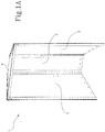
- the bulletproof wall comprises a central portion 2, at least two lateral portions 3, and a cover portion 4.
- the lateral portions 3 extend from opposite sides of the central portion 2 and diverge away from said central portion 2.
- the lateral portions 3 diverge symmetrically from the central portion 2 with an angle comprised between 25° and 35°, advantageously equal to 30°.
- the cover portion 4 extends above the central portion 2 and the lateral portions 3, diverging away from the central portion, so as to define a roofing that covers the volume enclosed by the central portion 2 together with the lateral portions 3.
- the aforementioned portions cooperate with each other to define a collection compartment inside which the residues of the projectiles are collected after they have hit the target during a shooting activity.
- the target 1 of the present invention provides a collection compartment configured to be positioned behind a ballistic target 16, so as to facilitate the collection of the fired bullets or their residual fragments.
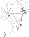
- the support 1 comprises a movable stand 5, preferably a towable or self-propelled trailer, which can be reversibly bonded to a lower portion of the support 1.
- protection means 7 are provided to prevent the fired bullets from hitting the wheels.
- a bulletproof plate can be positioned such that it is interposed, along any possible firing line, between the position point of a shooter and the wheels 6.
- the movable stand 5 comprises stabilising means 8, such as for example a plurality of stabilizers equipped with support bases located at peripheral points of the movable stand 5 in order to provide stable resting points which guarantee the non-mobility of the stand 5, and hence of the support 1, during the shooting activity.
- stabilising means 8 such as for example a plurality of stabilizers equipped with support bases located at peripheral points of the movable stand 5 in order to provide stable resting points which guarantee the non-mobility of the stand 5, and hence of the support 1, during the shooting activity.
- the support 1 preferably comprises a lower section 10 and an upper section 11.
- the upper section 11 is hinged to the lower section 10 along a hinge axis "X" and is rotatable around it.
- the lower section 10 comprises a first part of the central portion 2 and a first part of each of the lateral portions 3, while, instead, the upper section 11 comprises a second part of the central portion 2, a second part of each of the lateral portions 3 and the cover portion 4.
- the support 1 is configured to take a configuration of use, shown for example in Fig. 2 , in which the upper section 11 is arranged in abutment against the lower section 10, and a transport configuration, shown for example in Fig. 3 , in which the upper section 11 is not in abutment against the lower section 10.
- the upper section 11 is positioned behind the lower section 10 relative to the direction of movement of a projectile fired against the support 1.
- damping means 9 are provided, such as for example pistons, configured to dampen the rotatory motion of the upper section 11 when the latter is rotated about the hinge axis "X".
- the damping means 9 prevent that during the rotation of the upper section 11 the weight of the latter makes the manoeuvring difficult, with the risk of too fast and hardly controllable movements.
- the support 1 comprises at least one lever 12 reversibly attachable to the upper section 11 so as to facilitate the rotation of the upper section 11 itself around the hinge axis "X".
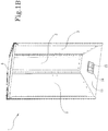
- the support 1 may comprise a support base 13, shown in detail in Fig. 1B , having a discharge opening 14 placed in communication with the collection compartment to facilitate the discharge of at least a part of a projectile from the collection compartment.
- the base 13 comprises an opening 14 through which the parts of the projectile collected in the compartment during the shooting activity can be cleared away, quickly removing in a highly efficient manner the waste of the activity, without the need to undertake long and costly interventions for the reclamation of the soil surrounding the shooting area.
- the support 1 comprises a drawer 15 configured to be inserted in the discharge opening 14 and adapted to collect and contain at least one part of a projectile when the latter is discharged from the collection compartment.
- Fig. 4 shows a possible embodiment of a support 1 for a ballistic target 16 under an operative condition, once the ballistic target 16 has been mounted.
- the lateral portions 3 comprise, preferably at one of their free end edges, fastening means 17 that allow the ballistic target 16 to be bonded in a stable, though reversible manner to the support 1.
- the ballistic target 16 once fixed to the support 1, defines, together with the bulletproof wall, a closed compartment for the collection of at least one projectile.
- the ballistic target 16 with the support 1 forms a closed containment chamber inside which the projectiles are conveniently and efficiently collected after they have struck and crossed the ballistic target 16 itself.
- the fastening means 17 may comprise a plurality of magnetic members, or a plurality of clamping screws.
- the fastening means 17 further comprise a sheet, which is preferably made of plastic material and can be reversibly bonded to the support 1, in particular to the lateral portions 3, so as to provide a support surface that improves the stability of the ballistic target 16 and prevents it from being torn by strong gusts of wind.
- a further object of the present invention is a movable support for a ballistic target 16 which comprises a trailer and a support 1 for a ballistic target 16 reversibly bonded to the trailer, wherein the support 1 comprises a bulletproof wall which has a central portion 2, at least two lateral portions 3 extending from opposite sides of the central portion 2 and diverging away from the central portion 2, and a cover portion 4 extending above the central portion 2 and the lateral portions 3 and diverging away from the central portion 2.
- the central portion 2, the lateral portions 3 and the cover portion 4 define, in mutual collaboration, a compartment for collecting at least one projectile.
- the support 1 is divided into a lower portion 10 and an upper portion 11 hinged to the lower portion 10 along a hinge axis "X" around which the upper portion 11 is rotatable.
- a support 1 for a ballistic target 16 allows for overcoming the drawbacks encountered in the prior art.
- a support 1 according to the present invention eliminates the need to carry out costly and complex operations for the reclamation of the land used for the shooting activity, since all the constituent elements of the projectile are stopped and collected into the collection compartment, without being dispersed in the area surrounding the target 16.
- the support 1 of the present invention is particularly versatile and efficient in that it provides for the presence of a movable stand 5, which allows the support to be conveniently moved if it needs to be moved to a different shooting area.
- the presence of the movable stand 5 makes the transport operation particularly convenient and secure, whilst at the same time guaranteeing a high stability thanks to the possibility of rotating the upper section 11 of the support 1 in such a way as to reduce the height of the centre of gravity of the whole support 1.
Landscapes
- Engineering & Computer Science (AREA)
- General Engineering & Computer Science (AREA)
- Aiming, Guidance, Guns With A Light Source, Armor, Camouflage, And Targets (AREA)
Claims (15)
- Träger (1) für ein ballistisches Ziel, umfassend eine kugelsichere Wand, die so konfiguriert ist, dass sie den Aufprall von mindestens einem Geschoss absorbiert, wobei die kugelsichere Wand einen zentralen Abschnitt (2), mindestens zwei seitliche Abschnitte (3), die sich von gegenüberliegenden Seiten des zentralen Abschnitts (2) erstrecken und von dem zentralen Abschnitt (2) weg divergieren und einem Abdeckabschnitt (4), der sich über den zentralen Abschnitt (2) und die seitlichen Abschnitte (3) erstreckt und vom zentralen Abschnitt (2) weg divergiert, umfasst; wobei der zentrale Abschnitt (2), die seitlichen Abschnitte (3) und der Abdeckabschnitt (4) in gegenseitiger Zusammenarbeit ein Fach zum Auffangen des mindestens einen Geschosses definieren; dadurch gekennzeichnet, dass er umfasst:- eine Trägerbasis (13) aufweisend eine Austrittsöffnung (14) in Kommunikation mit dem Auffangfach, um das Austreten von mindestens einem Teil eines Geschosses aus dem Auffangfach zu erleichtern,- eine Schublade (15), die so konfiguriert ist, dass sie in die Austrittsöffnung (14) eingesetzt werden kann und den mindestens einen Teil eines aus dem Auffangfach ausgetretenen Geschosses aufnimmt und enthält.
- Träger für ein ballistisches Ziel nach Anspruch 1, umfassend einen beweglichen Ständer (5), der reversibel an einem unteren Abschnitt des Trägers für ein ballistisches Ziel (16) anbringbar ist.
- Träger für ein ballistisches Ziel nach Anspruch 2, wobei der bewegliche Ständer (5) eine Vielzahl an Rädern (6) und kugelsicheren Schutzmitteln (7) umfasst, ausgelegt, um die Vielzahl an Rädern (6) abzuschirmen.
- Träger für ein ballistisches Ziel nach Anspruch 2 oder 3, wobei der bewegliche Ständer (5) Stabilisierungsmittel (8) umfasst, die geeignet sind, um zu verhindern, dass er sich während einer Schießaktivität bewegt.
- Träger für ein ballistisches Ziel nach einem oder mehreren der Ansprüche 2 bis 4, umfassend einen unteren Abschnitt (10) und einen oberen Abschnitt (11), der an dem unteren Abschnitt (10) entlang einer Gelenkachse (X) angelenkt und um diese herum drehbar ist.
- Träger für ein ballistisches Ziel nach Anspruch 5, wobei der untere Abschnitt (10) einen ersten Teil des zentralen Abschnitts (2) und einen ersten Teil von jedem der mindestens zwei seitlichen Abschnitte (3) umfasst und wobei der obere Abschnitt (11) einen zweiten Teil des zentralen Abschnitts (2), einen zweiten Teil jedes der mindestens zwei seitlichen Abschnitte (3) und den Abdeckabschnitt (4) umfasst.
- Träger für ein ballistisches Ziel nach Anspruch 6, der so konfiguriert ist, dass er eine Verwendungskonfiguration, in der der obere Abschnitt (11) in Anlage an dem unteren Abschnitt (10) angeordnet ist, und eine Transportkonfiguration übernimmt, in der der obere Abschnitt (11) nicht an dem unteren Abschnitt (10) anliegt.
- Träger für ein ballistisches Ziel nach einem oder mehreren der Ansprüche 5 bis 7, umfassend Dämpfungsmittel (9), ausgelegt, um die Rotationsbewegung des oberen Abschnitts (11) bei einer Drehung um die Gelenkachse (X) zu dämpfen.
- Träger für ein ballistisches Ziel nach einem oder mehreren der Ansprüche 5 bis 8, umfassend mindestens einen Hebel (12), der reversibel an dem oberen Abschnitt (11) anbringbar ist, ausgelegt, um die Drehung des oberen Abschnitts (11) um die Gelenkachse (X) zu fördern.
- Träger für ein ballistisches Ziel nach einem oder mehreren der vorhergehenden Ansprüche, wobei die seitlichen Abschnitte (3), vorzugsweise an einer ihrer freien Endkanten, Befestigungsmittel (17) umfassen, die konfiguriert sind, um ein ballistisches Ziel (16) an dem Träger reversibel anzubringen.
- Träger für ein ballistisches Ziel nach Anspruch 10, wobei die Befestigungsmittel (17) eine Vielzahl an magnetischen Elementen oder eine Vielzahl an Klemmschrauben umfassen.
- Träger für ein ballistisches Ziel nach Anspruch 10 oder 11, wobei die Befestigungsmittel (17) zudem eine Folie umfassen, vorzugsweise aus Kunststoffmaterial, die reversibel an den seitlichen Abschnitten (3) anbringbar ist und ausgelegt, um eine Trägerfläche für das ballistische Ziel (16) bereitzustellen.
- Träger für ein ballistisches Ziel nach einem oder mehreren der vorhergehenden Ansprüche, wobei die mindestens zwei seitlichen Abschnitte (3) in Bezug auf den zentralen Abschnitt (2) um einen Winkel zwischen 25° und 35° geneigt sind.
- Beweglicher Träger für ein ballistisches Ziel, dadurch gekennzeichnet, dass er einen Anhänger und einen Träger für ein ballistisches Ziel (16) nach Anspruch 1 umfasst, wobei der Träger für ein ballistisches Ziel (16) reversibel an den Anhänger gebunden ist.
- Beweglicher Träger für ein ballistisches Ziel nach Anspruch 14, wobei der Träger für ein ballistisches Ziel (16) in einen unteren Abschnitt und einen oberen Abschnitt unterteilt ist, der an dem unteren Abschnitt entlang einer Gelenkachse (X) angelenkt ist und um diese herum drehbar ist.
Priority Applications (4)
| Application Number | Priority Date | Filing Date | Title |
|---|---|---|---|
| PL17425041T PL3382322T3 (pl) | 2017-03-29 | 2017-03-29 | Nośnik dla tarczy balistycznej |
| EP17425041.5A EP3382322B1 (de) | 2017-03-29 | 2017-03-29 | Träger für ein ballistisches ziel |
| ES17425041T ES2741847T3 (es) | 2017-03-29 | 2017-03-29 | Soporte para objetivo balístico |
| DK17425041.5T DK3382322T3 (da) | 2017-03-29 | 2017-03-29 | Støtte til ballistisk mål |
Applications Claiming Priority (1)
| Application Number | Priority Date | Filing Date | Title |
|---|---|---|---|
| EP17425041.5A EP3382322B1 (de) | 2017-03-29 | 2017-03-29 | Träger für ein ballistisches ziel |
Publications (2)
| Publication Number | Publication Date |
|---|---|
| EP3382322A1 EP3382322A1 (de) | 2018-10-03 |
| EP3382322B1 true EP3382322B1 (de) | 2019-04-17 |
Family
ID=58669764
Family Applications (1)
| Application Number | Title | Priority Date | Filing Date |
|---|---|---|---|
| EP17425041.5A Active EP3382322B1 (de) | 2017-03-29 | 2017-03-29 | Träger für ein ballistisches ziel |
Country Status (4)
| Country | Link |
|---|---|
| EP (1) | EP3382322B1 (de) |
| DK (1) | DK3382322T3 (de) |
| ES (1) | ES2741847T3 (de) |
| PL (1) | PL3382322T3 (de) |
Citations (1)
| Publication number | Priority date | Publication date | Assignee | Title |
|---|---|---|---|---|
| US8827274B2 (en) * | 2012-05-18 | 2014-09-09 | Bullet Trap, LLC | Projectile containment system |
Family Cites Families (4)
| Publication number | Priority date | Publication date | Assignee | Title |
|---|---|---|---|---|
| DE9313702U1 (de) * | 1992-12-23 | 1993-11-18 | Mey, Klaus-Peter, Dipl.-Ing. Dipl.-Wirtsch.-Ing. Dr.-Ing., 50226 Frechen | Zielscheibe mit Halterung |
| US8313103B2 (en) * | 2009-08-13 | 2012-11-20 | O'neal Kerry | Portable projectile trap assembly |
| US8464460B1 (en) * | 2011-05-25 | 2013-06-18 | Clayton Chance Runyan | Transportable shooting bench and target |
| US20160003584A1 (en) * | 2013-07-09 | 2016-01-07 | Eric Durynski | Portable bullet trap |
-
2017
- 2017-03-29 DK DK17425041.5T patent/DK3382322T3/da active
- 2017-03-29 ES ES17425041T patent/ES2741847T3/es active Active
- 2017-03-29 EP EP17425041.5A patent/EP3382322B1/de active Active
- 2017-03-29 PL PL17425041T patent/PL3382322T3/pl unknown
Patent Citations (1)
| Publication number | Priority date | Publication date | Assignee | Title |
|---|---|---|---|---|
| US8827274B2 (en) * | 2012-05-18 | 2014-09-09 | Bullet Trap, LLC | Projectile containment system |
Also Published As
| Publication number | Publication date |
|---|---|
| DK3382322T3 (da) | 2019-07-29 |
| ES2741847T3 (es) | 2020-02-12 |
| EP3382322A1 (de) | 2018-10-03 |
| PL3382322T3 (pl) | 2019-10-31 |
Similar Documents
| Publication | Publication Date | Title |
|---|---|---|
| US9891029B2 (en) | Apparatus for collecting warheads | |
| US8091894B2 (en) | Military target system | |
| US20080185786A1 (en) | Triple tap target system | |
| US10378864B2 (en) | Ecological shooting training panel for any type and caliber ammunition | |
| KR102425550B1 (ko) | 도탄방지용 표적장치 | |
| KR100915517B1 (ko) | 소총 탄두 회수장치 | |
| KR101915799B1 (ko) | 방탄방패 | |
| EP3382322A1 (de) | Träger für ein ballistisches ziel | |
| KR102116752B1 (ko) | 스마트 실탄 사격 표적 시스템 | |
| KR20170110930A (ko) | 탄두 회수 장치 | |
| EP2362177A2 (de) | Schutzsystem für ein Fahrzeug | |
| US10473440B1 (en) | System for personalized berm | |
| KR102137448B1 (ko) | 탄두고 | |
| KR20170105260A (ko) | 고무충진부 및 개구부가 구비된 탄두회수장치. | |
| KR101945848B1 (ko) | 탄두 회수 장치 | |
| RU2331037C1 (ru) | Мобильное устройство для защиты с трансформируемым защитным экраном | |
| KR20180004070A (ko) | 고무충진부 및 개구부가 구비된 탄두회수장치. | |
| SK500942015U1 (sk) | Mobilný kontajnerový zachytávač balistických striel | |
| US20130328269A1 (en) | Stand-Alone Target Trap For Absorbing High Velocity Projectiles | |
| RU166926U1 (ru) | Скрывающееся модульное огневое сооружение | |
| RU118418U1 (ru) | Скрывающееся огневое сооружение дистанционного управления | |
| US20210148680A1 (en) | Apparatus for Target Shooting and Projectile Containment | |
| DE1941597A1 (de) | Anordnung,bestehend aus einer Infanteriewaffe und deren Munition | |
| KR102617668B1 (ko) | 도비탄 방지기능을 겸비한 탄두 회수장치 | |
| US20130019740A1 (en) | Method and apparatus for absorbing the energy of bullet impacts |
Legal Events
| Date | Code | Title | Description |
|---|---|---|---|
| STAA | Information on the status of an ep patent application or granted ep patent |
Free format text: STATUS: EXAMINATION IS IN PROGRESS |
|
| PUAI | Public reference made under article 153(3) epc to a published international application that has entered the european phase |
Free format text: ORIGINAL CODE: 0009012 |
|
| 17P | Request for examination filed |
Effective date: 20180522 |
|
| AK | Designated contracting states |
Kind code of ref document: A1 Designated state(s): AL AT BE BG CH CY CZ DE DK EE ES FI FR GB GR HR HU IE IS IT LI LT LU LV MC MK MT NL NO PL PT RO RS SE SI SK SM TR |
|
| AX | Request for extension of the european patent |
Extension state: BA ME |
|
| GRAP | Despatch of communication of intention to grant a patent |
Free format text: ORIGINAL CODE: EPIDOSNIGR1 |
|
| STAA | Information on the status of an ep patent application or granted ep patent |
Free format text: STATUS: GRANT OF PATENT IS INTENDED |
|
| INTG | Intention to grant announced |
Effective date: 20181105 |
|
| GRAS | Grant fee paid |
Free format text: ORIGINAL CODE: EPIDOSNIGR3 |
|
| GRAA | (expected) grant |
Free format text: ORIGINAL CODE: 0009210 |
|
| STAA | Information on the status of an ep patent application or granted ep patent |
Free format text: STATUS: THE PATENT HAS BEEN GRANTED |
|
| AK | Designated contracting states |
Kind code of ref document: B1 Designated state(s): AL AT BE BG CH CY CZ DE DK EE ES FI FR GB GR HR HU IE IS IT LI LT LU LV MC MK MT NL NO PL PT RO RS SE SI SK SM TR |
|
| REG | Reference to a national code |
Ref country code: GB Ref legal event code: FG4D |
|
| REG | Reference to a national code |
Ref country code: CH Ref legal event code: EP |
|
| REG | Reference to a national code |
Ref country code: DE Ref legal event code: R096 Ref document number: 602017003380 Country of ref document: DE |
|
| REG | Reference to a national code |
Ref country code: AT Ref legal event code: REF Ref document number: 1122033 Country of ref document: AT Kind code of ref document: T Effective date: 20190515 Ref country code: IE Ref legal event code: FG4D |
|
| REG | Reference to a national code |
Ref country code: RO Ref legal event code: EPE |
|
| REG | Reference to a national code |
Ref country code: DK Ref legal event code: T3 Effective date: 20190724 |
|
| REG | Reference to a national code |
Ref country code: NL Ref legal event code: FP |
|
| REG | Reference to a national code |
Ref country code: SE Ref legal event code: TRGR |
|
| REG | Reference to a national code |
Ref country code: CH Ref legal event code: NV Representative=s name: BUGNION S.A., CH |
|
| REG | Reference to a national code |
Ref country code: LT Ref legal event code: MG4D |
|
| REG | Reference to a national code |
Ref country code: NO Ref legal event code: T2 Effective date: 20190417 |
|
| PG25 | Lapsed in a contracting state [announced via postgrant information from national office to epo] |
Ref country code: HR Free format text: LAPSE BECAUSE OF FAILURE TO SUBMIT A TRANSLATION OF THE DESCRIPTION OR TO PAY THE FEE WITHIN THE PRESCRIBED TIME-LIMIT Effective date: 20190417 Ref country code: LT Free format text: LAPSE BECAUSE OF FAILURE TO SUBMIT A TRANSLATION OF THE DESCRIPTION OR TO PAY THE FEE WITHIN THE PRESCRIBED TIME-LIMIT Effective date: 20190417 Ref country code: PT Free format text: LAPSE BECAUSE OF FAILURE TO SUBMIT A TRANSLATION OF THE DESCRIPTION OR TO PAY THE FEE WITHIN THE PRESCRIBED TIME-LIMIT Effective date: 20190817 Ref country code: AL Free format text: LAPSE BECAUSE OF FAILURE TO SUBMIT A TRANSLATION OF THE DESCRIPTION OR TO PAY THE FEE WITHIN THE PRESCRIBED TIME-LIMIT Effective date: 20190417 |
|
| PG25 | Lapsed in a contracting state [announced via postgrant information from national office to epo] |
Ref country code: BG Free format text: LAPSE BECAUSE OF FAILURE TO SUBMIT A TRANSLATION OF THE DESCRIPTION OR TO PAY THE FEE WITHIN THE PRESCRIBED TIME-LIMIT Effective date: 20190717 Ref country code: GR Free format text: LAPSE BECAUSE OF FAILURE TO SUBMIT A TRANSLATION OF THE DESCRIPTION OR TO PAY THE FEE WITHIN THE PRESCRIBED TIME-LIMIT Effective date: 20190718 Ref country code: RS Free format text: LAPSE BECAUSE OF FAILURE TO SUBMIT A TRANSLATION OF THE DESCRIPTION OR TO PAY THE FEE WITHIN THE PRESCRIBED TIME-LIMIT Effective date: 20190417 Ref country code: LV Free format text: LAPSE BECAUSE OF FAILURE TO SUBMIT A TRANSLATION OF THE DESCRIPTION OR TO PAY THE FEE WITHIN THE PRESCRIBED TIME-LIMIT Effective date: 20190417 |
|
| PG25 | Lapsed in a contracting state [announced via postgrant information from national office to epo] |
Ref country code: IS Free format text: LAPSE BECAUSE OF FAILURE TO SUBMIT A TRANSLATION OF THE DESCRIPTION OR TO PAY THE FEE WITHIN THE PRESCRIBED TIME-LIMIT Effective date: 20190817 |
|
| REG | Reference to a national code |
Ref country code: DE Ref legal event code: R097 Ref document number: 602017003380 Country of ref document: DE |
|
| PG25 | Lapsed in a contracting state [announced via postgrant information from national office to epo] |
Ref country code: EE Free format text: LAPSE BECAUSE OF FAILURE TO SUBMIT A TRANSLATION OF THE DESCRIPTION OR TO PAY THE FEE WITHIN THE PRESCRIBED TIME-LIMIT Effective date: 20190417 Ref country code: SK Free format text: LAPSE BECAUSE OF FAILURE TO SUBMIT A TRANSLATION OF THE DESCRIPTION OR TO PAY THE FEE WITHIN THE PRESCRIBED TIME-LIMIT Effective date: 20190417 |
|
| REG | Reference to a national code |
Ref country code: ES Ref legal event code: FG2A Ref document number: 2741847 Country of ref document: ES Kind code of ref document: T3 Effective date: 20200212 |
|
| PLBE | No opposition filed within time limit |
Free format text: ORIGINAL CODE: 0009261 |
|
| STAA | Information on the status of an ep patent application or granted ep patent |
Free format text: STATUS: NO OPPOSITION FILED WITHIN TIME LIMIT |
|
| PG25 | Lapsed in a contracting state [announced via postgrant information from national office to epo] |
Ref country code: SM Free format text: LAPSE BECAUSE OF FAILURE TO SUBMIT A TRANSLATION OF THE DESCRIPTION OR TO PAY THE FEE WITHIN THE PRESCRIBED TIME-LIMIT Effective date: 20190417 |
|
| 26N | No opposition filed |
Effective date: 20200120 |
|
| PG25 | Lapsed in a contracting state [announced via postgrant information from national office to epo] |
Ref country code: MC Free format text: LAPSE BECAUSE OF FAILURE TO SUBMIT A TRANSLATION OF THE DESCRIPTION OR TO PAY THE FEE WITHIN THE PRESCRIBED TIME-LIMIT Effective date: 20190417 |
|
| PG25 | Lapsed in a contracting state [announced via postgrant information from national office to epo] |
Ref country code: LU Free format text: LAPSE BECAUSE OF NON-PAYMENT OF DUE FEES Effective date: 20200329 |
|
| REG | Reference to a national code |
Ref country code: AT Ref legal event code: UEP Ref document number: 1122033 Country of ref document: AT Kind code of ref document: T Effective date: 20190417 |
|
| PG25 | Lapsed in a contracting state [announced via postgrant information from national office to epo] |
Ref country code: IE Free format text: LAPSE BECAUSE OF NON-PAYMENT OF DUE FEES Effective date: 20200329 |
|
| PGFP | Annual fee paid to national office [announced via postgrant information from national office to epo] |
Ref country code: GB Payment date: 20220322 Year of fee payment: 6 Ref country code: FI Payment date: 20220318 Year of fee payment: 6 Ref country code: DK Payment date: 20220324 Year of fee payment: 6 Ref country code: DE Payment date: 20220329 Year of fee payment: 6 Ref country code: CH Payment date: 20220324 Year of fee payment: 6 Ref country code: AT Payment date: 20220318 Year of fee payment: 6 |
|
| PG25 | Lapsed in a contracting state [announced via postgrant information from national office to epo] |
Ref country code: MT Free format text: LAPSE BECAUSE OF FAILURE TO SUBMIT A TRANSLATION OF THE DESCRIPTION OR TO PAY THE FEE WITHIN THE PRESCRIBED TIME-LIMIT Effective date: 20190417 Ref country code: CY Free format text: LAPSE BECAUSE OF FAILURE TO SUBMIT A TRANSLATION OF THE DESCRIPTION OR TO PAY THE FEE WITHIN THE PRESCRIBED TIME-LIMIT Effective date: 20190417 |
|
| PGFP | Annual fee paid to national office [announced via postgrant information from national office to epo] |
Ref country code: TR Payment date: 20220315 Year of fee payment: 6 Ref country code: SE Payment date: 20220324 Year of fee payment: 6 Ref country code: RO Payment date: 20220321 Year of fee payment: 6 Ref country code: PL Payment date: 20220317 Year of fee payment: 6 Ref country code: NO Payment date: 20220322 Year of fee payment: 6 Ref country code: NL Payment date: 20220325 Year of fee payment: 6 Ref country code: FR Payment date: 20220325 Year of fee payment: 6 Ref country code: CZ Payment date: 20220328 Year of fee payment: 6 Ref country code: BE Payment date: 20220325 Year of fee payment: 6 |
|
| PG25 | Lapsed in a contracting state [announced via postgrant information from national office to epo] |
Ref country code: MK Free format text: LAPSE BECAUSE OF FAILURE TO SUBMIT A TRANSLATION OF THE DESCRIPTION OR TO PAY THE FEE WITHIN THE PRESCRIBED TIME-LIMIT Effective date: 20190417 |
|
| PGFP | Annual fee paid to national office [announced via postgrant information from national office to epo] |
Ref country code: ES Payment date: 20220418 Year of fee payment: 6 |
|
| PG25 | Lapsed in a contracting state [announced via postgrant information from national office to epo] |
Ref country code: SI Free format text: LAPSE BECAUSE OF FAILURE TO SUBMIT A TRANSLATION OF THE DESCRIPTION OR TO PAY THE FEE WITHIN THE PRESCRIBED TIME-LIMIT Effective date: 20190417 |
|
| REG | Reference to a national code |
Ref country code: DE Ref legal event code: R119 Ref document number: 602017003380 Country of ref document: DE |
|
| REG | Reference to a national code |
Ref country code: NO Ref legal event code: MMEP |
|
| PG25 | Lapsed in a contracting state [announced via postgrant information from national office to epo] |
Ref country code: RO Free format text: LAPSE BECAUSE OF NON-PAYMENT OF DUE FEES Effective date: 20230329 Ref country code: FI Free format text: LAPSE BECAUSE OF NON-PAYMENT OF DUE FEES Effective date: 20230329 Ref country code: CZ Free format text: LAPSE BECAUSE OF NON-PAYMENT OF DUE FEES Effective date: 20230329 |
|
| REG | Reference to a national code |
Ref country code: CH Ref legal event code: PL Ref country code: SE Ref legal event code: EUG |
|
| REG | Reference to a national code |
Ref country code: DK Ref legal event code: EBP Effective date: 20230331 |
|
| REG | Reference to a national code |
Ref country code: NL Ref legal event code: MM Effective date: 20230401 |
|
| REG | Reference to a national code |
Ref country code: AT Ref legal event code: MM01 Ref document number: 1122033 Country of ref document: AT Kind code of ref document: T Effective date: 20230329 |
|
| GBPC | Gb: european patent ceased through non-payment of renewal fee |
Effective date: 20230329 |
|
| REG | Reference to a national code |
Ref country code: BE Ref legal event code: MM Effective date: 20230331 |
|
| PG25 | Lapsed in a contracting state [announced via postgrant information from national office to epo] |
Ref country code: NL Free format text: LAPSE BECAUSE OF NON-PAYMENT OF DUE FEES Effective date: 20230401 |
|
| PG25 | Lapsed in a contracting state [announced via postgrant information from national office to epo] |
Ref country code: GB Free format text: LAPSE BECAUSE OF NON-PAYMENT OF DUE FEES Effective date: 20230329 |
|
| PG25 | Lapsed in a contracting state [announced via postgrant information from national office to epo] |
Ref country code: SE Free format text: LAPSE BECAUSE OF NON-PAYMENT OF DUE FEES Effective date: 20230330 Ref country code: NO Free format text: LAPSE BECAUSE OF NON-PAYMENT OF DUE FEES Effective date: 20230331 Ref country code: LI Free format text: LAPSE BECAUSE OF NON-PAYMENT OF DUE FEES Effective date: 20230331 Ref country code: GB Free format text: LAPSE BECAUSE OF NON-PAYMENT OF DUE FEES Effective date: 20230329 Ref country code: FR Free format text: LAPSE BECAUSE OF NON-PAYMENT OF DUE FEES Effective date: 20230331 Ref country code: DE Free format text: LAPSE BECAUSE OF NON-PAYMENT OF DUE FEES Effective date: 20231003 Ref country code: CH Free format text: LAPSE BECAUSE OF NON-PAYMENT OF DUE FEES Effective date: 20230331 Ref country code: AT Free format text: LAPSE BECAUSE OF NON-PAYMENT OF DUE FEES Effective date: 20230329 |
|
| PG25 | Lapsed in a contracting state [announced via postgrant information from national office to epo] |
Ref country code: BE Free format text: LAPSE BECAUSE OF NON-PAYMENT OF DUE FEES Effective date: 20230331 |
|
| PG25 | Lapsed in a contracting state [announced via postgrant information from national office to epo] |
Ref country code: DK Free format text: LAPSE BECAUSE OF NON-PAYMENT OF DUE FEES Effective date: 20230331 |
|
| REG | Reference to a national code |
Ref country code: ES Ref legal event code: FD2A Effective date: 20240507 |
|
| PG25 | Lapsed in a contracting state [announced via postgrant information from national office to epo] |
Ref country code: ES Free format text: LAPSE BECAUSE OF NON-PAYMENT OF DUE FEES Effective date: 20230330 |
|
| PG25 | Lapsed in a contracting state [announced via postgrant information from national office to epo] |
Ref country code: ES Free format text: LAPSE BECAUSE OF NON-PAYMENT OF DUE FEES Effective date: 20230330 |
|
| PG25 | Lapsed in a contracting state [announced via postgrant information from national office to epo] |
Ref country code: PL Free format text: LAPSE BECAUSE OF NON-PAYMENT OF DUE FEES Effective date: 20230329 |
|
| PG25 | Lapsed in a contracting state [announced via postgrant information from national office to epo] |
Ref country code: PL Free format text: LAPSE BECAUSE OF NON-PAYMENT OF DUE FEES Effective date: 20230329 |
|
| PGFP | Annual fee paid to national office [announced via postgrant information from national office to epo] |
Ref country code: IT Payment date: 20260319 Year of fee payment: 10 |