EP3382191A1 - Intake passage structure - Google Patents
Intake passage structure Download PDFInfo
- Publication number
- EP3382191A1 EP3382191A1 EP18161685.5A EP18161685A EP3382191A1 EP 3382191 A1 EP3382191 A1 EP 3382191A1 EP 18161685 A EP18161685 A EP 18161685A EP 3382191 A1 EP3382191 A1 EP 3382191A1
- Authority
- EP
- European Patent Office
- Prior art keywords
- constriction
- intake passage
- protrusion
- intake
- circumferential surface
- Prior art date
- Legal status (The legal status is an assumption and is not a legal conclusion. Google has not performed a legal analysis and makes no representation as to the accuracy of the status listed.)
- Granted
Links
Images


Classifications
-
- F—MECHANICAL ENGINEERING; LIGHTING; HEATING; WEAPONS; BLASTING
- F02—COMBUSTION ENGINES; HOT-GAS OR COMBUSTION-PRODUCT ENGINE PLANTS
- F02M—SUPPLYING COMBUSTION ENGINES IN GENERAL WITH COMBUSTIBLE MIXTURES OR CONSTITUENTS THEREOF
- F02M35/00—Combustion-air cleaners, air intakes, intake silencers, or induction systems specially adapted for, or arranged on, internal-combustion engines
- F02M35/10—Air intakes; Induction systems
- F02M35/10242—Devices or means connected to or integrated into air intakes; Air intakes combined with other engine or vehicle parts
- F02M35/10262—Flow guides, obstructions, deflectors or the like
-
- B—PERFORMING OPERATIONS; TRANSPORTING
- B60—VEHICLES IN GENERAL
- B60K—ARRANGEMENT OR MOUNTING OF PROPULSION UNITS OR OF TRANSMISSIONS IN VEHICLES; ARRANGEMENT OR MOUNTING OF PLURAL DIVERSE PRIME-MOVERS IN VEHICLES; AUXILIARY DRIVES FOR VEHICLES; INSTRUMENTATION OR DASHBOARDS FOR VEHICLES; ARRANGEMENTS IN CONNECTION WITH COOLING, AIR INTAKE, GAS EXHAUST OR FUEL SUPPLY OF PROPULSION UNITS IN VEHICLES
- B60K11/00—Arrangement in connection with cooling of propulsion units
- B60K11/06—Arrangement in connection with cooling of propulsion units with air cooling
-
- B—PERFORMING OPERATIONS; TRANSPORTING
- B62—LAND VEHICLES FOR TRAVELLING OTHERWISE THAN ON RAILS
- B62J—CYCLE SADDLES OR SEATS; AUXILIARY DEVICES OR ACCESSORIES SPECIALLY ADAPTED TO CYCLES AND NOT OTHERWISE PROVIDED FOR, e.g. ARTICLE CARRIERS OR CYCLE PROTECTORS
- B62J40/00—Arrangements of air cleaners specially adapted for cycles
- B62J40/10—Arrangements of air cleaners specially adapted for cycles characterised by air duct arrangements
-
- B—PERFORMING OPERATIONS; TRANSPORTING
- B62—LAND VEHICLES FOR TRAVELLING OTHERWISE THAN ON RAILS
- B62M—RIDER PROPULSION OF WHEELED VEHICLES OR SLEDGES; POWERED PROPULSION OF SLEDGES OR SINGLE-TRACK CYCLES; TRANSMISSIONS SPECIALLY ADAPTED FOR SUCH VEHICLES
- B62M7/00—Motorcycles characterised by position of motor or engine
- B62M7/02—Motorcycles characterised by position of motor or engine with engine between front and rear wheels
-
- F—MECHANICAL ENGINEERING; LIGHTING; HEATING; WEAPONS; BLASTING
- F02—COMBUSTION ENGINES; HOT-GAS OR COMBUSTION-PRODUCT ENGINE PLANTS
- F02B—INTERNAL-COMBUSTION PISTON ENGINES; COMBUSTION ENGINES IN GENERAL
- F02B37/00—Engines characterised by provision of pumps driven at least for part of the time by exhaust
- F02B37/04—Engines with exhaust drive and other drive of pumps, e.g. with exhaust-driven pump and mechanically-driven second pump
-
- F—MECHANICAL ENGINEERING; LIGHTING; HEATING; WEAPONS; BLASTING
- F02—COMBUSTION ENGINES; HOT-GAS OR COMBUSTION-PRODUCT ENGINE PLANTS
- F02D—CONTROLLING COMBUSTION ENGINES
- F02D9/00—Controlling engines by throttling air or fuel-and-air induction conduits or exhaust conduits
- F02D9/02—Controlling engines by throttling air or fuel-and-air induction conduits or exhaust conduits concerning induction conduits
-
- F—MECHANICAL ENGINEERING; LIGHTING; HEATING; WEAPONS; BLASTING
- F02—COMBUSTION ENGINES; HOT-GAS OR COMBUSTION-PRODUCT ENGINE PLANTS
- F02D—CONTROLLING COMBUSTION ENGINES
- F02D9/00—Controlling engines by throttling air or fuel-and-air induction conduits or exhaust conduits
- F02D9/08—Throttle valves specially adapted therefor; Arrangements of such valves in conduits
- F02D9/10—Throttle valves specially adapted therefor; Arrangements of such valves in conduits having pivotally-mounted flaps
-
- F—MECHANICAL ENGINEERING; LIGHTING; HEATING; WEAPONS; BLASTING
- F02—COMBUSTION ENGINES; HOT-GAS OR COMBUSTION-PRODUCT ENGINE PLANTS
- F02M—SUPPLYING COMBUSTION ENGINES IN GENERAL WITH COMBUSTIBLE MIXTURES OR CONSTITUENTS THEREOF
- F02M35/00—Combustion-air cleaners, air intakes, intake silencers, or induction systems specially adapted for, or arranged on, internal-combustion engines
- F02M35/10—Air intakes; Induction systems
- F02M35/10091—Air intakes; Induction systems characterised by details of intake ducts: shapes; connections; arrangements
- F02M35/10098—Straight ducts
-
- F—MECHANICAL ENGINEERING; LIGHTING; HEATING; WEAPONS; BLASTING
- F02—COMBUSTION ENGINES; HOT-GAS OR COMBUSTION-PRODUCT ENGINE PLANTS
- F02M—SUPPLYING COMBUSTION ENGINES IN GENERAL WITH COMBUSTIBLE MIXTURES OR CONSTITUENTS THEREOF
- F02M35/00—Combustion-air cleaners, air intakes, intake silencers, or induction systems specially adapted for, or arranged on, internal-combustion engines
- F02M35/10—Air intakes; Induction systems
- F02M35/10091—Air intakes; Induction systems characterised by details of intake ducts: shapes; connections; arrangements
- F02M35/10118—Air intakes; Induction systems characterised by details of intake ducts: shapes; connections; arrangements with variable cross-sections of intake ducts along their length; Venturis; Diffusers
-
- F—MECHANICAL ENGINEERING; LIGHTING; HEATING; WEAPONS; BLASTING
- F02—COMBUSTION ENGINES; HOT-GAS OR COMBUSTION-PRODUCT ENGINE PLANTS
- F02M—SUPPLYING COMBUSTION ENGINES IN GENERAL WITH COMBUSTIBLE MIXTURES OR CONSTITUENTS THEREOF
- F02M35/00—Combustion-air cleaners, air intakes, intake silencers, or induction systems specially adapted for, or arranged on, internal-combustion engines
- F02M35/10—Air intakes; Induction systems
- F02M35/10091—Air intakes; Induction systems characterised by details of intake ducts: shapes; connections; arrangements
- F02M35/10124—Ducts with special cross-sections, e.g. non-circular cross-section
-
- F—MECHANICAL ENGINEERING; LIGHTING; HEATING; WEAPONS; BLASTING
- F02—COMBUSTION ENGINES; HOT-GAS OR COMBUSTION-PRODUCT ENGINE PLANTS
- F02M—SUPPLYING COMBUSTION ENGINES IN GENERAL WITH COMBUSTIBLE MIXTURES OR CONSTITUENTS THEREOF
- F02M35/00—Combustion-air cleaners, air intakes, intake silencers, or induction systems specially adapted for, or arranged on, internal-combustion engines
- F02M35/10—Air intakes; Induction systems
- F02M35/10091—Air intakes; Induction systems characterised by details of intake ducts: shapes; connections; arrangements
- F02M35/10137—Flexible ducts, e.g. bellows or hoses
-
- F—MECHANICAL ENGINEERING; LIGHTING; HEATING; WEAPONS; BLASTING
- F02—COMBUSTION ENGINES; HOT-GAS OR COMBUSTION-PRODUCT ENGINE PLANTS
- F02M—SUPPLYING COMBUSTION ENGINES IN GENERAL WITH COMBUSTIBLE MIXTURES OR CONSTITUENTS THEREOF
- F02M35/00—Combustion-air cleaners, air intakes, intake silencers, or induction systems specially adapted for, or arranged on, internal-combustion engines
- F02M35/10—Air intakes; Induction systems
- F02M35/10091—Air intakes; Induction systems characterised by details of intake ducts: shapes; connections; arrangements
- F02M35/10144—Connections of intake ducts to each other or to another device
-
- F—MECHANICAL ENGINEERING; LIGHTING; HEATING; WEAPONS; BLASTING
- F02—COMBUSTION ENGINES; HOT-GAS OR COMBUSTION-PRODUCT ENGINE PLANTS
- F02M—SUPPLYING COMBUSTION ENGINES IN GENERAL WITH COMBUSTIBLE MIXTURES OR CONSTITUENTS THEREOF
- F02M35/00—Combustion-air cleaners, air intakes, intake silencers, or induction systems specially adapted for, or arranged on, internal-combustion engines
- F02M35/10—Air intakes; Induction systems
- F02M35/10314—Materials for intake systems
- F02M35/10321—Plastics; Composites; Rubbers
-
- F—MECHANICAL ENGINEERING; LIGHTING; HEATING; WEAPONS; BLASTING
- F02—COMBUSTION ENGINES; HOT-GAS OR COMBUSTION-PRODUCT ENGINE PLANTS
- F02M—SUPPLYING COMBUSTION ENGINES IN GENERAL WITH COMBUSTIBLE MIXTURES OR CONSTITUENTS THEREOF
- F02M35/00—Combustion-air cleaners, air intakes, intake silencers, or induction systems specially adapted for, or arranged on, internal-combustion engines
- F02M35/12—Intake silencers ; Sound modulation, transmission or amplification
- F02M35/1205—Flow throttling or guiding
- F02M35/1211—Flow throttling or guiding by using inserts in the air intake flow path, e.g. baffles, throttles or orifices; Flow guides
-
- F—MECHANICAL ENGINEERING; LIGHTING; HEATING; WEAPONS; BLASTING
- F02—COMBUSTION ENGINES; HOT-GAS OR COMBUSTION-PRODUCT ENGINE PLANTS
- F02M—SUPPLYING COMBUSTION ENGINES IN GENERAL WITH COMBUSTIBLE MIXTURES OR CONSTITUENTS THEREOF
- F02M35/00—Combustion-air cleaners, air intakes, intake silencers, or induction systems specially adapted for, or arranged on, internal-combustion engines
- F02M35/16—Combustion-air cleaners, air intakes, intake silencers, or induction systems specially adapted for, or arranged on, internal-combustion engines characterised by use in vehicles
- F02M35/162—Motorcycles; All-terrain vehicles, e.g. quads, snowmobiles; Small vehicles, e.g. forklifts
-
- F—MECHANICAL ENGINEERING; LIGHTING; HEATING; WEAPONS; BLASTING
- F02—COMBUSTION ENGINES; HOT-GAS OR COMBUSTION-PRODUCT ENGINE PLANTS
- F02D—CONTROLLING COMBUSTION ENGINES
- F02D41/00—Electrical control of supply of combustible mixture or its constituents
- F02D41/0002—Controlling intake air
-
- Y—GENERAL TAGGING OF NEW TECHNOLOGICAL DEVELOPMENTS; GENERAL TAGGING OF CROSS-SECTIONAL TECHNOLOGIES SPANNING OVER SEVERAL SECTIONS OF THE IPC; TECHNICAL SUBJECTS COVERED BY FORMER USPC CROSS-REFERENCE ART COLLECTIONS [XRACs] AND DIGESTS
- Y02—TECHNOLOGIES OR APPLICATIONS FOR MITIGATION OR ADAPTATION AGAINST CLIMATE CHANGE
- Y02T—CLIMATE CHANGE MITIGATION TECHNOLOGIES RELATED TO TRANSPORTATION
- Y02T10/00—Road transport of goods or passengers
- Y02T10/10—Internal combustion engine [ICE] based vehicles
- Y02T10/12—Improving ICE efficiencies
Definitions
- the present invention relates generally to intake passage structures and, more particularly, to an intake passage structure applied to an intake passage connected with an intake port of an engine.
- a known structure includes a throttle valve, disposed midway in an intake passage connected with an intake port of an engine, for changing a flow passage area of the intake passage.
- Patent Document 1 discloses an arrangement in which an intake passage has a protrusion that protrudes, at a position upstream of a throttle valve, to the inside of the intake passage to thereby change a flow passage shape.
- a protrusion can affect, for example, an intake air amount and an intake air flow with respect to a throttle valve opening in any desired manner.
- Patent Document 1 JP-A-H2-105540
- the protrusion of the arrangement disclosed in Patent Document 1 is disposed on an inner circumferential surface that has been thickened without an outline of the intake passage being changed.
- the protrusion represents an increase in weight and a user, for example, can machine the protrusion to change the flow passage shape.
- the present invention has a first feature in that an intake passage structure applicable to an intake passage (30) connected with an intake port (37) of an engine (18) and formed by connecting a plurality of parts including a throttle body (41) having a throttle valve (42), the intake passage structure comprising the plurality of parts include a constriction part (50, 150, 350) having a protrusion (60, 160, 360) that protrudes on an inner circumferential surface side of the intake passage (30), wherein the constriction part (50, 150, 350) includes cylindrical connections (52, 56, 152, 156, 352, 356) disposed on both sides of a constriction path (55, 155, 355) in which the protrusion (60, 160, 360) is formed, the connections (52, 56, 152, 156, 352, 356) connecting upstream and downstream parts, the constriction path (55, 155, 355) has an outer circumferential surface (62, 162, 362) recessed inwardly in a
- the present invention has a second feature in that the constriction path (55, 155, 355) has a uniform wall thickness.
- the present invention has a third feature in that the constriction part (50, 150, 350) is a connecting tube connected upstream of the throttle body (41).
- the present invention has a fourth feature in that the constriction part (50, 150, 350) is formed of an elastic material, and the constriction path (55, 155, 355) has a rib (54, 154, 354) disposed on the outer circumferential surface (62, 162, 362) in a standing condition, the rib (54, 154, 354) connecting between the connections (52, 56, 152, 156, 352, 356).
- the present invention has a fifth feature in that the intake passage (30) is formed to extend linearly.
- the present invention has a sixth feature in that a constriction opening (59) constricted by an apex (60a) of the protrusion (60) has a circular cross-sectional shape concentric with the connections (52, 56).
- the present invention has a seventh feature in that the protrusion (160) protrudes inwardly in a radial direction from a vehicle body inferior side of the constriction path (155), and the protrusion (160) forms a wall (160c) that extends substantially perpendicularly to a flow passage direction.
- the present invention has an eighth feature in that a constriction opening (359) constricted by an apex (360a) of the protrusion (360) has an elliptical cross-sectional shape long in the vehicle width direction having a center at a position offset on the vehicle body inferior side with respect to the connections (352, 356).
- the portion at which the protrusion is formed can have a minimized wall thickness, so that the weight of the intake passage can be prevented from increasing. Additionally, machining the protrusion results in a thinner wall thickness of the outer wall of the constriction path and in reduced strength. Thus, a user, for example, can be dissuaded from machining the protrusion to thereby change a flow passage shape.
- the constriction path (55, 155, 355) has a uniform wall thickness. Therefore, an effect of preventing the flow passage shape from being changed can be enhanced, while reduction in weight of the constriction part is promoted.
- the constriction part (50, 150, 350) is a connecting tube connected upstream of the throttle body (41). Therefore, an intake air amount is constricted at a position upstream of the throttle valve. This can reduce pressure load applied to the throttle valve, while reducing engine noise.
- the constriction part (50, 150, 350) is formed of an elastic material, and the constriction path (55, 155, 355) has a rib (54, 154, 354) disposed on the outer circumferential surface (62, 162, 362) in a standing condition, the rib (54, 154, 354) connecting between the connections (52, 56, 152, 156, 352, 356). Therefore, the constriction part formed of an elastic material facilitates connection with the upstream and downstream parts. Additionally, rigidity enhanced by the rib allows deformation resistance of the constriction path to be enhanced.
- the intake passage (30) is formed to extend linearly. Therefore, coupling rigidity among different parts constituting the intake passage can be easily enhanced and force to bend the intake passage is not likely to occur, so that the constriction part can be prevented from being deformed.
- a constriction opening (59) constricted by an apex (60a) of the protrusion (60) has a circular cross-sectional shape concentric with the connections (52, 56). Therefore, rigidity of the constriction path can be readily made uniform in a circumferential direction.
- the protrusion (160) protrudes inwardly in a radial direction from a vehicle body inferior side of the constriction path (155), and the protrusion (160) forms a wall (160c) that extends substantially perpendicularly to a flow passage direction. Therefore, even when a mixture heavier than air flows back along an inner circumferential surface on the vehicle body inferior side of the intake passage due to mixture spit-back, the wall of the protrusion is allowed to receive the mixture. Thus, the spit-back mixture can be prevented from reaching an air cleaner box and sticking to an air filter.
- a constriction opening (359) constricted by an apex (360a) of the protrusion (360) has an elliptical cross-sectional shape long in the vehicle width direction having a center at a position offset on the vehicle body inferior side with respect to the connections (352, 356). Therefore, the intake flow passage is thus constricted to achieve reduced engine noise.
- the constriction opening disposed at the position offset inferiorly in the vehicle body results in the constriction opening being disposed on the inferior side in the vehicle body on which the intake passage starts to open as a throttle valve initiates an opening operation. This enables smooth inflow of the mixture particularly when a throttle opening remains small.
- Fig. 1 is a left side elevational view of a motorcycle 1 to which an intake passage structure according to an embodiment of the present invention is applied.
- the motorcycle 1 is an off-road saddled vehicle that travels by transmitting driving power of an engine 18 as a power source to a rear wheel WR.
- a head pipe 5 is disposed at a vehicle body anterior end portion of a vehicle body frame 2.
- the head pipe 5 oscillatably journals a steering stem not depicted.
- a pair of left and right front forks 15 is supported by a top bridge 7 and a bottom bridge 10 that are fixed to the steering stem at upper and lower portions, respectively, of the head pipe 5.
- the front forks 15 rotatably journal a front wheel WF.
- a steering handlebar 6 is mounted on an upper portion of the top bridge 7.
- the engine 18 is disposed at a lower portion of the vehicle body frame 2.
- a pivot 20 is disposed at a rear end lower portion of the vehicle body frame 2.
- the pivot 20 swingably journals a front end portion of a swing arm 22.
- the swing arm 22 rotatably journals the rear wheel WR.
- a rear cushion 21 suspends an anterior side of the swing arm 22 on the vehicle body frame 2.
- a pair of left and right steps 19 is disposed inferior to the pivot 20. A rider can rest his or her feet on the steps 19.
- a headlight 12, a pair of left and right direction indicators 13, a meter unit 8, and a screen 9 are disposed anterior to the steering handlebar 6.
- the headlight 12 is fixed to the side of the head pipe 5.
- the meter unit 8 displays information such as a speedometer and an odometer.
- the screen 9 covers an area around the headlight 12.
- a front fender 14 is disposed inferior to the direction indicators 13. The front fender 14 is fixed to the front forks 15.
- a fuel tank 4 is disposed between the steering handlebar 6 and a seat 28.
- the fuel tank 4 is fixed to the vehicle body frame 2.
- a side cowl 29 is disposed inferior to the seat 28 and a seat cowl 27 is disposed posterior to the seat 28.
- a pair of left and right radiator shrouds 11 is disposed outside the respective front forks 15 in a vehicle width direction.
- a pair of left and right side covers 3 is connected posteriorly with rear portions of the radiator shrouds 11.
- a taillight unit 25 and a pair of left and right rear-side direction indicators 26 are disposed posterior to the seat cowl 27.
- a rear fender 24 is disposed inferior to the taillight unit 25.
- An exhaust pipe 17 is connected with an exhaust port disposed at a vehicle body anterior side of a cylinder head 16 of the engine 18.
- the exhaust pipe 17 guides combustion gas to a muffler 23.
- An intake passage 30 is connected with an intake port disposed at a vehicle body posterior side of the cylinder head 16.
- An intake passage structure according to an embodiment of the present invention is applied to the intake passage 30.
- An air cleaner box 70 is connected upstream of the intake passage 30.
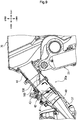
- Fig. 2 is a partial enlarged cross-sectional view of parts around the intake passage 30 in the motorcycle 1.
- the cylinder head 16 of the engine 18 has an exhaust port 35 and an intake port 37.
- the exhaust pipe 17 is connected with the exhaust port 35.
- the intake passage 30 is connected with the intake port 37.
- a valve actuating mechanism 33 for intake and exhaust valves and an ignition plug 34 are disposed in the cylinder head 16.
- a cylinder head cover 32 covers an upper opening in the cylinder head 16.
- a fuel pump 31 is disposed at a bottom portion of the fuel tank 4 disposed superior to the cylinder head cover 32. The fuel pump 31 sends fuel under pressure to an injector 43 disposed in the intake passage 30.
- the intake passage 30 has a read end portion connected with a front surface portion of the air cleaner box 70.
- the rear cushion 21 including a reservoir tank 38 is disposed inferior to the intake passage 30 and the air cleaner box 70.
- the air cleaner box 70 has a recess 70a formed on a vehicle body anterior side thereof. The recess 70a is intended to avoid interference with the reservoir tank 38.
- the air cleaner box 70 includes a front-side half body 73 and a rear-side half body 76.
- the front-side half body 73 has the recess 70a formed therein.
- the rear-side half body 76 houses an air filter 74.
- An intake pipe 75 is mounted on an upper surface of the rear-side half body 76. Outside air is drawn in the intake pipe 75 from a portion inferior to the seat 28.
- a battery 39 is disposed posterior to the intake pipe 75.
- the battery 39 supplies electric power to a starter motor and a headlight, for example.
- the front-side half body 73 of the air cleaner box 70 includes a front portion 71 and a rear portion 72 coupled with each other.
- the intake passage 30 has a rear end portion fixed into an opening in the front portion 71.
- the intake passage 30 forms a linear intake flow passage between the intake port 37 and the air cleaner box 70.
- the intake passage 30 includes a connection ring 40, a throttle body 41, a connecting tube 50, and an intake funnel 44.
- the connection ring 40 is formed of an elastic material such as rubber.
- the throttle body 41 formed of metal, includes the injector 43 and a throttle valve 42.
- the connecting tube 50 is formed of an elastic material such as rubber.
- the intake funnel 44 is formed of, for example, a hard synthetic resin.
- connection ring 40, the throttle body 41, the connecting tube 50, and the intake funnel 44 are arranged in sequence from the anterior side of the vehicle body and connected with each other to constitute the intake passage 30.
- the linearly formed intake passage 30 allows coupling rigidity among different parts to be enhanced and prevents force to bend the intake passage 30 from being readily generated.
- Fig. 3 is a partial enlarged view of the parts around the intake passage 30 depicted in Fig. 2 .
- the connection ring 40 has a through hole 45 formed in a right lateral surface thereof in the vehicle width direction. A control vacuum for an EGR valve that recirculates exhaust gas to the intake port 37 is taken from the through hole 45.
- the connection ring 40 has a downstream end covering an outer circumference of an upstream end of a metal pipe that constitutes the intake port 37 and fixed tightly by a thin plate-shaped band 40a. Additionally, the connection ring 40 has an upstream end covering an outer circumference of a downstream end of the throttle body 41 and fixed tightly by a thin plate-shaped band 40b.
- the connecting tube 50 has a downstream end covering an outer circumference of an upstream end of the throttle body 41 and fixed tightly by a thin plate-shaped band 47.
- the connecting tube 50 has an upstream end covering an outer circumference of a downstream end of the intake funnel 44 and fixed tightly by a thin plate-shaped band 48.
- the connecting tube 50 of the embodiment has a protrusion that protrudes largely on an inner circumferential surface side thereof so as to function as a constriction part constricting a passage for intake air.
- the connection of the connecting tube 50 having the protrusion with the upstream side of the throttle body 41 enables reduction in engine noise and load of an intake air vacuum applied to the butterfly type throttle valve 42.
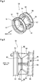
- Fig. 4 is a perspective view of the connecting tube 50 (hereinafter, may be referred to also as a constriction part).
- Fig. 5 is a side elevational view of the constriction part 50.
- Fig. 6 is a front elevational view of the constriction part 50 as viewed from the engine side.
- Fig. 7 is a cross-sectional view taken along line VII-VII in Fig. 6 .
- Fig. 8 is a cross-sectional view taken along line VIII-VIII in Fig. 5 .
- the constriction part 50 includes a constriction path 55, a first connection 52, and a second connection 56.
- the constriction path 55 has a protrusion 60 formed to protrude on the inner circumferential side.
- the first connection 52 and the second connection 56 are disposed on both ends of the constriction path 55.
- the first connection 52 connected with an end outer circumference of the throttle body 41 has a positioning tab 53 for the band 47.
- the positioning tab 53 is disposed on an outer circumferential portion of the first connection 52.
- the second connection 56 connected with an end outer circumference of the intake funnel 44 has a positioning tab 57 for the band 48.
- the positioning tab 57 is disposed on an outer circumferential portion of the second connection 56.
- Ribs are provided in a standing condition throughout an entire circumference on both ends of the outer circumference on which each of the positioning tabs 53 and 57 is formed.
- the ribs guide positions in a flow passage direction of the bands 47 and 48.
- the first connection 52 has engagement protrusions 51 to be engaged with the throttle body 41 and the second connection 56 has an indicator plate 58 indicating an assembling direction.
- the engagement protrusions 51 are disposed on an end face of the first connection 52.
- the indicator plate 58 is disposed on a guide rib end face of the second connection 56.
- the intake flow passage in the first connection 52 has a circular cross-sectional shape that is substantially identical to a cross-sectional shape of the second connection 56.
- the constriction path 55 is configured such that a cylindrical member having a uniform wall thickness has a lateral surface recessed inwardly in a radial direction.
- the protrusion 60 in the embodiment is formed such that the intake flow passage in the first connection 52 and the second connection 56 is constricted so as to taper toward a circular constriction opening 59 formed by an apex 60a and an outer circumferential surface 62 of the constriction path 55 is formed to follow the shape of the protrusion 60.
- the outer circumferential surface 62 has a most recessed portion 62a disposed inside the inner circumferential surface 52a of the first connection 52 and the inner circumferential surface 56a of the second connection 56 in the radial direction.
- the constriction path 55 of the constriction part 50 is formed of a plate member having a substantially uniform (e.g., 4 mm) wall thickness.
- the weight of the constriction part 50 can be prevented from increasing even when the protrusion 60 protrudes largely on the inner circumferential side of the constriction part 50.
- machining the protrusion 60 causes an outer wall of the constriction path 55 to have a thinner thickness, resulting in reduced strength.
- a user for example, can be prevented from attempting to machine the protrusion 60 to thereby change the flow passage shape.
- Ribs 54 are disposed on the outer circumferential surface 62 of the constriction path 55.
- the ribs 54 connect between the first connection 52 and the second connection 56.
- the ribs 54 four in total, are disposed at 90 degrees intervals to extend in the flow passage direction.
- the ribs 54 each have a wall thickness substantially identical to the wall thickness of the constriction path 55. This arrangement enhances rigidity and deformation resistance of the constriction path 55, while minimizing an increase in weight.
- the ribs 54 may each be, for example, marked on a lateral surface so as to prevent erroneous assembly during the assembly procedure.
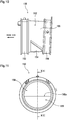
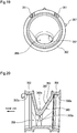
- Fig. 9 is a cross-sectional view of a configuration of an intake passage 30a to which a constriction part 150 according to a second embodiment of the present invention is applied.
- Fig. 10 is a side elevational view of the constriction part 150.
- Fig. 11 is a front elevational view of the constriction part 150 as viewed from the engine side.
- Fig. 12 is a cross-sectional view taken along line XII-XII in Fig. 11 .
- the constriction part 150 differs from the constriction part 50 described with reference to the first embodiment only in a shape of a constriction path 155.
- a protrusion 160 that protrudes on an inner circumferential side of the constriction path 155 has a shape that occupies substantially half of the intake flow passage on a vehicle body inferior side.
- the protrusion 160 has an apex 160a extending in the vehicle width direction.
- the protrusion 160 further includes a taper 160b and a wall 160c.
- the taper 160b gradually constricts the flow passage shape toward a constriction opening 159.
- the wall 160c extends perpendicularly to the flow passage direction.
- the shape of the constriction path 155 described above constricts the intake flow passage to thereby reduce load of an intake air vacuum applied to the throttle valve 42, while reducing engine noise.
- the shape of the constriction path 155 allows the wall 160c to receive the mixture.
- the spit-back mixture can be prevented from reaching the air cleaner box 70 and sticking to the air filter 74.
- the constriction path 155 of the constriction part 150 is formed of a plate member having a substantially uniform wall thickness and having the protrusion 160 does not readily increase the weight of the constriction part 150. Additionally, machining the protrusion 160 causes an outer wall of the constriction path 155 to have a thinner thickness, resulting in reduced strength. Thus, the user, for example, can be prevented from attempting to machine the protrusion 160 to thereby change the flow passage shape.
- a rib 154 is disposed at a position corresponding to the protrusion 160 on an outer circumferential surface 162 of the constriction path 155. The rib 154 connects between a first connection 152 and a second connection 156. The rib 154 enhances rigidity and deformation resistance of the constriction path 155, while minimizing an increase in weight.
- Fig. 13 is a cross-sectional view of a constriction part 250 according to a third embodiment of the present invention.
- the constriction part 250 differs from the constriction part 50 described with reference to the first embodiment in a shape of a constriction path 255.
- a protrusion 260 that protrudes on an inner circumferential side of the constriction path 255 is formed into a closed-bottom box shape that protrudes from the vehicle body superior side to the vehicle body inferior side of the intake flow passage.
- a lid 280 is fitted to close an opening in an upper portion of the protrusion 260.
- the protrusion 260 has a lateral surface on the engine side, in which a through hole 270 is formed.
- the protrusion 260 constricts the intake flow passage to a constriction opening 259. Additionally, a space enclosed by an outer circumferential surface 262 of the protrusion 260 and the lid 280 functions as a resonator chamber, so that intake noise can be reduced.
- Fig. 14 is a cross-sectional view of a joint structure between the intake funnel 44 that constitutes the rear end portion of the intake passage 30 and the air cleaner box 70.
- the intake funnel 44 is inserted, from a posterior side of the vehicle body, in an opening 77 in the front portion 71 of the front-side half body 73 that forms part of the air cleaner box 70.
- a first flange 71a that constitutes a perimeter of the opening 77 and a second flange 44a formed at a rear end of the intake funnel 44 are then subjected to thermal welding throughout an entire circumference indicated by the arrow in Fig. 14 .
- the second flange 44a on the vehicle body inferior side is formed into an end of a plate member extending inferiorly in a standing condition from the intake funnel 44, thereby enhancing support rigidity with respect to the opening 77.
- Fig. 15 is an enlarged cross-sectional view of the thermally welded portion.
- the first flange 71a of the front portion 71 has a first annular protrusion 71b that is formed into a circularly annular shape extending over an entire circumference.
- the second flange 44a of the intake funnel 44 has a surface on the engine side, on which a second annular protrusion 44b that is formed into a circularly annular shape extending over an entire circumference is formed.
- the first annular protrusion 71b is formed by machining two grooves in an inner wall 71c of the front portion 71. Additionally, the first annular protrusion 71b has an apex disposed at a position lower than the inner wall 71c.
- the foregoing arrangements result in the following. Specifically, when the first flange 71a and the second flange 44a are fixed through thermal welding, the ceiling surface of the first annular protrusion 71b contacts the ceiling surface of the second annular protrusion 44b and, in addition, the inner wall 71c of the first flange 71a contacts one surface of the second flange 44a on the inside and outside in the radial direction of the annular protrusions. Stress can thus be applied uniformly to the annular protrusions during the thermal welding and coupling rigidity by the thermal welding can be enhanced.
- Fig. 16 is a cross-sectional view of the connection ring 40.
- the connection ring 40 has the first through hole 45 formed in the right lateral surface thereof in the vehicle width direction.
- a control vacuum for the EGR valve that recirculates exhaust gas to the intake port 37 is taken from the first through hole 45.
- the connection ring 40 further has a second through hole 46 formed in the left lateral surface thereof in the vehicle width direction. Evaporative gas adsorbed by a charcoal canister is drawn in through the second through hole 46.
- connection ring 40 is shaped to be bilaterally symmetrical. Cylindrical portions 40a protruding to the outside from the respective through holes 45 and 46 are also shaped to be identical to each other. A common part may therefore be manufactured for a metal pipe joint 80 for connecting lines 85 and 86 with the respective through holes 45 and 46, so that production cost can be reduced.
- the pipe joint 80 includes an inside pipe 83 and an outside pipe 81 across a flange 82.
- the inside pipe 83 protrudes into the inside of the intake flow passage.
- the outside pipe 81 receives each of the lines 85 and 86 inserted thereover.
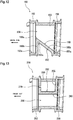
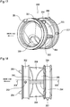
- Fig. 17 is a perspective view of a constriction part 350 according to a fourth embodiment of the present invention.
- Fig. 18 is a side elevational view of the constriction part 350.
- Fig. 19 is a front elevational view of the constriction part 350 as viewed from the engine side.
- Fig. 20 is a cross-sectional view taken along line XX-XX in Fig. 18 .
- the constriction part 350 differs from the constriction part 50 described with reference to Figs. 4 to 8 only in shapes of a constriction path 355 and ribs 354.
- the constriction part 350 includes a cylindrical first connection 352 and a cylindrical second connection 356 disposed across the constriction path 355 that has a protrusion 360 protruding on an inner circumferential side.
- the first connection 352 connected with the end outer circumference of the throttle body 41 has a positioning tab 353 for the band 47.
- the positioning tab 353 is disposed on an outer circumferential portion of the first connection 352.
- the second connection 356 connected with the end outer circumference of the intake funnel 44 has a positioning tab 357 for the band 48.
- the positioning tab 357 is disposed on an outer circumferential portion of the second connection 356. Ribs are provided in a standing condition throughout an entire circumference on both ends of the outer circumference on which each of the positioning tabs 353 and 357 is formed. The ribs guide positions in the flow passage direction of the bands 47 and 48. Additionally, to prevent erroneous assembly during the assembly procedure, the first connection 352 has engagement protrusions 351 to be engaged with the throttle body 41 and the second connection 356 has an indicator plate 358 indicating an assembling direction. Specifically, the engagement protrusions 351 are disposed on an end face of the first connection 352. The indicator plate 358 is disposed on a guide rib end face of the second connection 356.
- the intake flow passage in the first connection 352 has a circular cross-sectional shape that is substantially identical to a cross-sectional shape of the second connection 356.
- the constriction path 355 is configured such that a cylindrical member having a uniform wall thickness has a lateral surface recessed inwardly in a radial direction.
- the protrusion 360 in the embodiment is formed such that the intake flow passage in the first connection 352 and the second connection 356 is constricted so as to taper toward a constriction opening 359 that is formed at a position offset inferiorly in the vehicle body by an apex 360a and an outer circumferential surface 362 of the constriction path 355 is formed to follow the shape of the protrusion 360.
- the constriction opening 359 is formed into a substantially elliptical shape having a major axis oriented toward the vehicle width direction.
- the outer circumferential surface 362 has a most recessed portion 362a disposed inside the inner circumferential surface 352a of the first connection 352 and the inner circumferential surface 356a of the second connection 356 in the radial direction.
- constriction path 355 constricts the intake flow passage to thereby reduce engine noise.
- constriction opening 359 disposed at the position offset inferiorly in the vehicle body results in the constriction opening 359 being disposed on the inferior side in the vehicle body on which the intake passage starts to open as the throttle valve 42 initiates an opening operation. This enables smooth inflow of the mixture particularly when the throttle opening remains small.
- the ribs 354 are disposed on the outer circumferential surface 362 of the constriction path 355.
- the ribs 354 connect between the first connection 352 and the second connection 356.
- the ribs 354, three in total, are disposed at 90 degrees intervals to extend in the flow passage direction.
- the ribs 354 each have a wall thickness substantially identical to the wall thickness of the constriction path 355. This arrangement enhances rigidity and deformation resistance of the constriction path 355, while minimizing an increase in weight.
- parts that constitute the intake passage include the constriction part that includes the cylindrical connections disposed across the constriction path that has the protrusion formed therein.
- the constriction path has the outer circumferential surface recessed inwardly in the radial direction so as to follow the shape of the protrusion and the most recessed portion of the outer circumferential surface is disposed inside the inner circumferential surfaces of the connections in the radial direction.
- the construction and configuration of the motorcycle, shape and construction of the intake passage, shape of the intake port, shape and construction of the throttle body and the intake funnel, shape and material of the constriction part, and the like described above are illustrative only and not limiting and various changes may be made therein.
- the position of the opening constricted by the apex of the protrusion may be changed in various ways in the flow passage direction or the radial direction.
- the intake passage structure according to the embodiments of the present invention can be applied to, not only motorcycles, but also various other types of vehicles in which the engine intake port is connected with the air cleaner box by an intake passage.
- a plurality of parts that constitute an intake passage (30) connected with an intake port (37) of an engine (18) include a constriction part (50) that has a protrusion (60) formed to protrude on an inner circumferential surface side of the intake passage (30).
- the constriction part (50) includes cylindrical connections (52, 56) disposed on both sides of a constriction path (55) in which the protrusion (60) is formed.
- the constriction path (55) has an outer circumferential surface (62) recessed inwardly in a radial direction so as to follow a shape of the protrusion (60).
- a portion recessed most (62a) of the recessed outer circumferential surface (62) is disposed inside inner circumferential surfaces (52a, 56a) of the connections (52, 56) in the radial direction.
- the constriction path (55) has a uniform wall thickness.
- the constriction part (50) is connected upstream of the throttle body (41).
Landscapes
- Engineering & Computer Science (AREA)
- Chemical & Material Sciences (AREA)
- Combustion & Propulsion (AREA)
- Mechanical Engineering (AREA)
- General Engineering & Computer Science (AREA)
- Transportation (AREA)
- Control Of Throttle Valves Provided In The Intake System Or In The Exhaust System (AREA)
Abstract
Description
- The present invention relates generally to intake passage structures and, more particularly, to an intake passage structure applied to an intake passage connected with an intake port of an engine.
- A known structure includes a throttle valve, disposed midway in an intake passage connected with an intake port of an engine, for changing a flow passage area of the intake passage.
- Patent Document 1 discloses an arrangement in which an intake passage has a protrusion that protrudes, at a position upstream of a throttle valve, to the inside of the intake passage to thereby change a flow passage shape. Such a protrusion can affect, for example, an intake air amount and an intake air flow with respect to a throttle valve opening in any desired manner.
- Patent Document 1:
JP-A-H2-105540 - The protrusion of the arrangement disclosed in Patent Document 1 is disposed on an inner circumferential surface that has been thickened without an outline of the intake passage being changed. Thus, unfortunately, the protrusion represents an increase in weight and a user, for example, can machine the protrusion to change the flow passage shape.
- It is an object of the present invention to solve the foregoing problems and to provide an intake passage structure that can, through a simple structure, achieve reduction in weight of an intake passage and prevent a flow passage shape from being changed.
- To achieve the afore-mentioned object, the present invention has a first feature in that an intake passage structure applicable to an intake passage (30) connected with an intake port (37) of an engine (18) and formed by connecting a plurality of parts including a throttle body (41) having a throttle valve (42), the intake passage structure comprising the plurality of parts include a constriction part (50, 150, 350) having a protrusion (60, 160, 360) that protrudes on an inner circumferential surface side of the intake passage (30), wherein the constriction part (50, 150, 350) includes cylindrical connections (52, 56, 152, 156, 352, 356) disposed on both sides of a constriction path (55, 155, 355) in which the protrusion (60, 160, 360) is formed, the connections (52, 56, 152, 156, 352, 356) connecting upstream and downstream parts, the constriction path (55, 155, 355) has an outer circumferential surface (62, 162, 362) recessed inwardly in a radial direction so as to follow a shape of the protrusion (60), and a portion recessed most (62a, 162a, 362a) of the recessed outer circumferential surface (62, 162, 362) is disposed inside inner circumferential surfaces (52a, 56a, 152a, 156a, 352a, 356a) of the connections (52, 56, 152, 156, 352, 356) in the radial direction.
- The present invention has a second feature in that the constriction path (55, 155, 355) has a uniform wall thickness.
- The present invention has a third feature in that the constriction part (50, 150, 350) is a connecting tube connected upstream of the throttle body (41).
- The present invention has a fourth feature in that the constriction part (50, 150, 350) is formed of an elastic material, and the constriction path (55, 155, 355) has a rib (54, 154, 354) disposed on the outer circumferential surface (62, 162, 362) in a standing condition, the rib (54, 154, 354) connecting between the connections (52, 56, 152, 156, 352, 356).
- The present invention has a fifth feature in that the intake passage (30) is formed to extend linearly.
- The present invention has a sixth feature in that a constriction opening (59) constricted by an apex (60a) of the protrusion (60) has a circular cross-sectional shape concentric with the connections (52, 56).
- The present invention has a seventh feature in that the protrusion (160) protrudes inwardly in a radial direction from a vehicle body inferior side of the constriction path (155), and the protrusion (160) forms a wall (160c) that extends substantially perpendicularly to a flow passage direction.
- The present invention has an eighth feature in that a constriction opening (359) constricted by an apex (360a) of the protrusion (360) has an elliptical cross-sectional shape long in the vehicle width direction having a center at a position offset on the vehicle body inferior side with respect to the connections (352, 356).
- According to the first feature of the present invention, an intake passage structure applicable to an intake passage (30) connected with an intake port (37) of an engine (18) and formed by connecting a plurality of parts including a throttle body (41) having a throttle valve (42), the intake passage structure comprising the plurality of parts include a constriction part (50, 150, 350) having a protrusion (60, 160, 360) that protrudes on an inner circumferential surface side of the intake passage (30), wherein the constriction part (50, 150, 350) includes cylindrical connections (52, 56, 152, 156, 352, 356) disposed on both sides of a constriction path (55, 155, 355) in which the protrusion (60, 160, 360) is formed, the connections (52, 56, 152, 156, 352, 356) connecting upstream and downstream parts, the constriction path (55, 155, 355) has an outer circumferential surface (62, 162, 362) recessed inwardly in a radial direction so as to follow a shape of the protrusion (60), and a portion recessed most (62a, 162a, 362a) of the recessed outer circumferential surface (62, 162, 362) is disposed inside inner circumferential surfaces (52a, 56a, 152a, 156a, 352a, 356a) of the connections (52, 56, 152, 156, 352, 356) in the radial direction. Therefore, even with a large protrusion formed on the inner circumferential surface of the constriction part, the portion at which the protrusion is formed can have a minimized wall thickness, so that the weight of the intake passage can be prevented from increasing. Additionally, machining the protrusion results in a thinner wall thickness of the outer wall of the constriction path and in reduced strength. Thus, a user, for example, can be dissuaded from machining the protrusion to thereby change a flow passage shape.
- According to the second feature of the present invention, the constriction path (55, 155, 355) has a uniform wall thickness. Therefore, an effect of preventing the flow passage shape from being changed can be enhanced, while reduction in weight of the constriction part is promoted.
- According to the third feature of the present invention, the constriction part (50, 150, 350) is a connecting tube connected upstream of the throttle body (41). Therefore, an intake air amount is constricted at a position upstream of the throttle valve. This can reduce pressure load applied to the throttle valve, while reducing engine noise.
- According to the fourth feature of the present invention, the constriction part (50, 150, 350) is formed of an elastic material, and the constriction path (55, 155, 355) has a rib (54, 154, 354) disposed on the outer circumferential surface (62, 162, 362) in a standing condition, the rib (54, 154, 354) connecting between the connections (52, 56, 152, 156, 352, 356). Therefore, the constriction part formed of an elastic material facilitates connection with the upstream and downstream parts. Additionally, rigidity enhanced by the rib allows deformation resistance of the constriction path to be enhanced.
- According to the fifth feature of the present invention, the intake passage (30) is formed to extend linearly. Therefore, coupling rigidity among different parts constituting the intake passage can be easily enhanced and force to bend the intake passage is not likely to occur, so that the constriction part can be prevented from being deformed.
- According to the sixth feature of the present invention, a constriction opening (59) constricted by an apex (60a) of the protrusion (60) has a circular cross-sectional shape concentric with the connections (52, 56). Therefore, rigidity of the constriction path can be readily made uniform in a circumferential direction.
- According to the seventh feature of the present invention, the protrusion (160) protrudes inwardly in a radial direction from a vehicle body inferior side of the constriction path (155), and the protrusion (160) forms a wall (160c) that extends substantially perpendicularly to a flow passage direction. Therefore, even when a mixture heavier than air flows back along an inner circumferential surface on the vehicle body inferior side of the intake passage due to mixture spit-back, the wall of the protrusion is allowed to receive the mixture. Thus, the spit-back mixture can be prevented from reaching an air cleaner box and sticking to an air filter.
- According to the eighth feature of the present invention, a constriction opening (359) constricted by an apex (360a) of the protrusion (360) has an elliptical cross-sectional shape long in the vehicle width direction having a center at a position offset on the vehicle body inferior side with respect to the connections (352, 356). Therefore, the intake flow passage is thus constricted to achieve reduced engine noise. In addition, the constriction opening disposed at the position offset inferiorly in the vehicle body results in the constriction opening being disposed on the inferior side in the vehicle body on which the intake passage starts to open as a throttle valve initiates an opening operation. This enables smooth inflow of the mixture particularly when a throttle opening remains small.
-
-
Fig. 1 is a left side elevational view of a motorcycle to which an intake passage structure according to an embodiment of the present invention is applied. -
Fig. 2 is a partial enlarged cross-sectional view of parts around theintake passage 30 in the motorcycle. -
Fig. 3 is a partial enlarged view of the parts around the intake passage depicted inFig. 2 . -
Fig. 4 is a perspective view of the constriction part. -
Fig. 5 is a side elevational view of the constriction part. -
Fig. 6 is a front elevational view of theconstriction part 50 as viewed from the engine side. -
Fig. 7 is a cross-sectional view taken along line VII-VII inFig. 6 . -
Fig. 8 is a cross-sectional view taken along line VIII-VIII inFig. 5 . -
Fig. 9 is a cross-sectional view of an intake passage structures to which a constriction part according to a second embodiment is applied. -
Fig. 10 is a side elevational view of the constriction part according to a second embodiment. -
Fig. 11 is a front elevational view of theconstriction part 150 as viewed from the engine side. -
Fig. 12 is a cross-sectional view taken along line XII-XII inFig. 11 . -
Fig. 13 is a cross-sectional view of a constriction part according to a third embodiment. -
Fig. 14 is a cross-sectional view of a joint structure between the intake funnel that constitutes the rear end portion of the intake passage and the air cleaner box. -
Fig. 15 is an enlarged cross-sectional view of the thermally welded portion. -
Fig. 16 is a cross-sectional view of the connection ring. -
Fig. 17 is a perspective view of a constriction part according to a fourth embodiment of the present invention. -
Fig. 18 is a side elevational view of the constriction part according to a fourth embodiment. -
Fig. 19 is a front elevational view of the constriction part according to a fourth embodiment as viewed from the engine side. -
Fig. 20 is a cross-sectional view taken along line XX-XX inFig. 18 . - A specific preferred embodiment to which the present invention is applied will be described below with reference to the accompanying drawings.
Fig. 1 is a left side elevational view of a motorcycle 1 to which an intake passage structure according to an embodiment of the present invention is applied. The motorcycle 1 is an off-road saddled vehicle that travels by transmitting driving power of anengine 18 as a power source to a rear wheel WR. - A
head pipe 5 is disposed at a vehicle body anterior end portion of avehicle body frame 2. Thehead pipe 5 oscillatably journals a steering stem not depicted. A pair of left and rightfront forks 15 is supported by atop bridge 7 and abottom bridge 10 that are fixed to the steering stem at upper and lower portions, respectively, of thehead pipe 5. Thefront forks 15 rotatably journal a front wheel WF. A steering handlebar 6 is mounted on an upper portion of thetop bridge 7. - The
engine 18 is disposed at a lower portion of thevehicle body frame 2. Apivot 20 is disposed at a rear end lower portion of thevehicle body frame 2. Thepivot 20 swingably journals a front end portion of aswing arm 22. Theswing arm 22 rotatably journals the rear wheel WR. Arear cushion 21 suspends an anterior side of theswing arm 22 on thevehicle body frame 2. A pair of left andright steps 19 is disposed inferior to thepivot 20. A rider can rest his or her feet on thesteps 19. - A
headlight 12, a pair of left andright direction indicators 13, ameter unit 8, and ascreen 9 are disposed anterior to the steering handlebar 6. Theheadlight 12 is fixed to the side of thehead pipe 5. Themeter unit 8 displays information such as a speedometer and an odometer. Thescreen 9 covers an area around theheadlight 12. Afront fender 14 is disposed inferior to thedirection indicators 13. Thefront fender 14 is fixed to thefront forks 15. - A
fuel tank 4 is disposed between the steering handlebar 6 and aseat 28. Thefuel tank 4 is fixed to thevehicle body frame 2. Aside cowl 29 is disposed inferior to theseat 28 and aseat cowl 27 is disposed posterior to theseat 28. A pair of left and right radiator shrouds 11 is disposed outside the respectivefront forks 15 in a vehicle width direction. A pair of left and right side covers 3 is connected posteriorly with rear portions of the radiator shrouds 11. Ataillight unit 25 and a pair of left and right rear-side direction indicators 26 are disposed posterior to theseat cowl 27. Arear fender 24 is disposed inferior to thetaillight unit 25. - An
exhaust pipe 17 is connected with an exhaust port disposed at a vehicle body anterior side of acylinder head 16 of theengine 18. Theexhaust pipe 17 guides combustion gas to amuffler 23. Anintake passage 30 is connected with an intake port disposed at a vehicle body posterior side of thecylinder head 16. An intake passage structure according to an embodiment of the present invention is applied to theintake passage 30. An aircleaner box 70 is connected upstream of theintake passage 30. -
Fig. 2 is a partial enlarged cross-sectional view of parts around theintake passage 30 in the motorcycle 1. As described previously, thecylinder head 16 of theengine 18 has anexhaust port 35 and anintake port 37. Theexhaust pipe 17 is connected with theexhaust port 35. Theintake passage 30 is connected with theintake port 37. Avalve actuating mechanism 33 for intake and exhaust valves and anignition plug 34 are disposed in thecylinder head 16. Acylinder head cover 32 covers an upper opening in thecylinder head 16. Afuel pump 31 is disposed at a bottom portion of thefuel tank 4 disposed superior to thecylinder head cover 32. Thefuel pump 31 sends fuel under pressure to aninjector 43 disposed in theintake passage 30. - The
intake passage 30 has a read end portion connected with a front surface portion of theair cleaner box 70. Therear cushion 21 including areservoir tank 38 is disposed inferior to theintake passage 30 and theair cleaner box 70. Theair cleaner box 70 has arecess 70a formed on a vehicle body anterior side thereof. Therecess 70a is intended to avoid interference with thereservoir tank 38. Theair cleaner box 70 includes a front-side half body 73 and a rear-side half body 76. The front-side half body 73 has therecess 70a formed therein. The rear-side half body 76 houses anair filter 74. Anintake pipe 75 is mounted on an upper surface of the rear-side half body 76. Outside air is drawn in theintake pipe 75 from a portion inferior to theseat 28. Abattery 39 is disposed posterior to theintake pipe 75. Thebattery 39 supplies electric power to a starter motor and a headlight, for example. - The front-
side half body 73 of theair cleaner box 70 includes afront portion 71 and arear portion 72 coupled with each other. Theintake passage 30 has a rear end portion fixed into an opening in thefront portion 71. Theintake passage 30 forms a linear intake flow passage between theintake port 37 and theair cleaner box 70. Theintake passage 30 includes aconnection ring 40, athrottle body 41, a connectingtube 50, and anintake funnel 44. Theconnection ring 40 is formed of an elastic material such as rubber. Thethrottle body 41, formed of metal, includes theinjector 43 and athrottle valve 42. The connectingtube 50 is formed of an elastic material such as rubber. Theintake funnel 44 is formed of, for example, a hard synthetic resin. Theconnection ring 40, thethrottle body 41, the connectingtube 50, and theintake funnel 44 are arranged in sequence from the anterior side of the vehicle body and connected with each other to constitute theintake passage 30. In the embodiment, the linearly formedintake passage 30 allows coupling rigidity among different parts to be enhanced and prevents force to bend theintake passage 30 from being readily generated. -
Fig. 3 is a partial enlarged view of the parts around theintake passage 30 depicted inFig. 2 . Theconnection ring 40 has a throughhole 45 formed in a right lateral surface thereof in the vehicle width direction. A control vacuum for an EGR valve that recirculates exhaust gas to theintake port 37 is taken from the throughhole 45. Theconnection ring 40 has a downstream end covering an outer circumference of an upstream end of a metal pipe that constitutes theintake port 37 and fixed tightly by a thin plate-shapedband 40a. Additionally, theconnection ring 40 has an upstream end covering an outer circumference of a downstream end of thethrottle body 41 and fixed tightly by a thin plate-shapedband 40b. The connectingtube 50 has a downstream end covering an outer circumference of an upstream end of thethrottle body 41 and fixed tightly by a thin plate-shapedband 47. The connectingtube 50 has an upstream end covering an outer circumference of a downstream end of theintake funnel 44 and fixed tightly by a thin plate-shapedband 48. During assembling and servicing the vehicle, the elastic force of theconnection ring 40 and the connectingtube 50 enables each of the parts to be easily removed and reinstalled, enhances the airtightness by being fastened by thebands engine 18 from being transmitted to thethrottle body 41 and theair cleaner box 70. - The connecting
tube 50 of the embodiment has a protrusion that protrudes largely on an inner circumferential surface side thereof so as to function as a constriction part constricting a passage for intake air. The connection of the connectingtube 50 having the protrusion with the upstream side of thethrottle body 41 enables reduction in engine noise and load of an intake air vacuum applied to the butterflytype throttle valve 42. -
Fig. 4 is a perspective view of the connecting tube 50 (hereinafter, may be referred to also as a constriction part).Fig. 5 is a side elevational view of theconstriction part 50.Fig. 6 is a front elevational view of theconstriction part 50 as viewed from the engine side.Fig. 7 is a cross-sectional view taken along line VII-VII inFig. 6 .Fig. 8 is a cross-sectional view taken along line VIII-VIII inFig. 5 . - The
constriction part 50 includes aconstriction path 55, afirst connection 52, and asecond connection 56. Theconstriction path 55 has aprotrusion 60 formed to protrude on the inner circumferential side. Thefirst connection 52 and thesecond connection 56, each having a cylindrical shape, are disposed on both ends of theconstriction path 55. Thefirst connection 52 connected with an end outer circumference of thethrottle body 41 has apositioning tab 53 for theband 47. Thepositioning tab 53 is disposed on an outer circumferential portion of thefirst connection 52. Thesecond connection 56 connected with an end outer circumference of theintake funnel 44 has apositioning tab 57 for theband 48. Thepositioning tab 57 is disposed on an outer circumferential portion of thesecond connection 56. Ribs are provided in a standing condition throughout an entire circumference on both ends of the outer circumference on which each of thepositioning tabs bands first connection 52 hasengagement protrusions 51 to be engaged with thethrottle body 41 and thesecond connection 56 has anindicator plate 58 indicating an assembling direction. Specifically, theengagement protrusions 51 are disposed on an end face of thefirst connection 52. Theindicator plate 58 is disposed on a guide rib end face of thesecond connection 56. - When the
throttle body 41 is connected with thefirst connection 52, the end outer circumference of thethrottle body 41 contacts an innercircumferential surface 52a of thefirst connection 52. This results in the intake flow passage in thefirst connection 52 being formed by an inner circumferential surface of thethrottle body 41. When theintake funnel 44 is connected with thesecond connection 56, the end outer circumference of theintake funnel 44 contacts an innercircumferential surface 56a of thesecond connection 56. This results in the intake flow passage in thesecond connection 56 being formed by an inner circumferential surface of theintake funnel 44. The intake flow passage in thefirst connection 52 has a circular cross-sectional shape that is substantially identical to a cross-sectional shape of thesecond connection 56. - The
constriction path 55 is configured such that a cylindrical member having a uniform wall thickness has a lateral surface recessed inwardly in a radial direction. Theprotrusion 60 in the embodiment is formed such that the intake flow passage in thefirst connection 52 and thesecond connection 56 is constricted so as to taper toward a circular constriction opening 59 formed by an apex 60a and an outercircumferential surface 62 of theconstriction path 55 is formed to follow the shape of theprotrusion 60. Additionally, the outercircumferential surface 62 has a most recessedportion 62a disposed inside the innercircumferential surface 52a of thefirst connection 52 and the innercircumferential surface 56a of thesecond connection 56 in the radial direction. - As described above, the
constriction path 55 of theconstriction part 50 is formed of a plate member having a substantially uniform (e.g., 4 mm) wall thickness. Thus, the weight of theconstriction part 50 can be prevented from increasing even when theprotrusion 60 protrudes largely on the inner circumferential side of theconstriction part 50. Additionally, machining theprotrusion 60 causes an outer wall of theconstriction path 55 to have a thinner thickness, resulting in reduced strength. Thus, a user, for example, can be prevented from attempting to machine theprotrusion 60 to thereby change the flow passage shape. -
Ribs 54 are disposed on the outercircumferential surface 62 of theconstriction path 55. Theribs 54 connect between thefirst connection 52 and thesecond connection 56. Theribs 54, four in total, are disposed at 90 degrees intervals to extend in the flow passage direction. Theribs 54 each have a wall thickness substantially identical to the wall thickness of theconstriction path 55. This arrangement enhances rigidity and deformation resistance of theconstriction path 55, while minimizing an increase in weight. Theribs 54 may each be, for example, marked on a lateral surface so as to prevent erroneous assembly during the assembly procedure. -
Fig. 9 is a cross-sectional view of a configuration of anintake passage 30a to which aconstriction part 150 according to a second embodiment of the present invention is applied.Fig. 10 is a side elevational view of theconstriction part 150.Fig. 11 is a front elevational view of theconstriction part 150 as viewed from the engine side.Fig. 12 is a cross-sectional view taken along line XII-XII inFig. 11 . - The
constriction part 150 differs from theconstriction part 50 described with reference to the first embodiment only in a shape of aconstriction path 155. Aprotrusion 160 that protrudes on an inner circumferential side of theconstriction path 155 has a shape that occupies substantially half of the intake flow passage on a vehicle body inferior side. Theprotrusion 160 has an apex 160a extending in the vehicle width direction. Theprotrusion 160 further includes ataper 160b and awall 160c. Thetaper 160b gradually constricts the flow passage shape toward aconstriction opening 159. Thewall 160c extends perpendicularly to the flow passage direction. - The shape of the
constriction path 155 described above constricts the intake flow passage to thereby reduce load of an intake air vacuum applied to thethrottle valve 42, while reducing engine noise. In addition, even when a mixture heavier than air flows back along an inner circumferential surface on the vehicle body inferior side of theintake passage 30a due to mixture spit-back, the shape of theconstriction path 155 allows thewall 160c to receive the mixture. Thus, the spit-back mixture can be prevented from reaching theair cleaner box 70 and sticking to theair filter 74. - As with the
constriction part 50 described earlier, theconstriction path 155 of theconstriction part 150 is formed of a plate member having a substantially uniform wall thickness and having theprotrusion 160 does not readily increase the weight of theconstriction part 150. Additionally, machining theprotrusion 160 causes an outer wall of theconstriction path 155 to have a thinner thickness, resulting in reduced strength. Thus, the user, for example, can be prevented from attempting to machine theprotrusion 160 to thereby change the flow passage shape. Arib 154 is disposed at a position corresponding to theprotrusion 160 on an outercircumferential surface 162 of theconstriction path 155. Therib 154 connects between afirst connection 152 and asecond connection 156. Therib 154 enhances rigidity and deformation resistance of theconstriction path 155, while minimizing an increase in weight. -
Fig. 13 is a cross-sectional view of aconstriction part 250 according to a third embodiment of the present invention. Theconstriction part 250 differs from theconstriction part 50 described with reference to the first embodiment in a shape of aconstriction path 255. Aprotrusion 260 that protrudes on an inner circumferential side of theconstriction path 255 is formed into a closed-bottom box shape that protrudes from the vehicle body superior side to the vehicle body inferior side of the intake flow passage. Alid 280 is fitted to close an opening in an upper portion of theprotrusion 260. Theprotrusion 260 has a lateral surface on the engine side, in which a throughhole 270 is formed. - In the
constriction path 255 according to the third embodiment, theprotrusion 260 constricts the intake flow passage to aconstriction opening 259. Additionally, a space enclosed by an outercircumferential surface 262 of theprotrusion 260 and thelid 280 functions as a resonator chamber, so that intake noise can be reduced. -
Fig. 14 is a cross-sectional view of a joint structure between theintake funnel 44 that constitutes the rear end portion of theintake passage 30 and theair cleaner box 70. Theintake funnel 44 is inserted, from a posterior side of the vehicle body, in anopening 77 in thefront portion 71 of the front-side half body 73 that forms part of theair cleaner box 70. Afirst flange 71a that constitutes a perimeter of theopening 77 and asecond flange 44a formed at a rear end of theintake funnel 44 are then subjected to thermal welding throughout an entire circumference indicated by the arrow inFig. 14 . Thesecond flange 44a on the vehicle body inferior side is formed into an end of a plate member extending inferiorly in a standing condition from theintake funnel 44, thereby enhancing support rigidity with respect to theopening 77. -
Fig. 15 is an enlarged cross-sectional view of the thermally welded portion. Thefirst flange 71a of thefront portion 71 has a firstannular protrusion 71b that is formed into a circularly annular shape extending over an entire circumference. Thesecond flange 44a of theintake funnel 44 has a surface on the engine side, on which a secondannular protrusion 44b that is formed into a circularly annular shape extending over an entire circumference is formed. The firstannular protrusion 71b is formed by machining two grooves in aninner wall 71c of thefront portion 71. Additionally, the firstannular protrusion 71b has an apex disposed at a position lower than theinner wall 71c. - When the
intake funnel 44 is inserted into theopening 77 in thefront portion 71 from the vehicle body posterior side, a ceiling surface of the firstannular protrusion 71b contacts a ceiling surface of the secondannular protrusion 44b and thesecond flange 44a abuts on theinner wall 71c of thefirst flange 71a. The thermal welding is performed such that the secondannular protrusion 44b is pressed against the firstannular protrusion 71b from the inside of thefront portion 71. - The foregoing arrangements result in the following. Specifically, when the
first flange 71a and thesecond flange 44a are fixed through thermal welding, the ceiling surface of the firstannular protrusion 71b contacts the ceiling surface of the secondannular protrusion 44b and, in addition, theinner wall 71c of thefirst flange 71a contacts one surface of thesecond flange 44a on the inside and outside in the radial direction of the annular protrusions. Stress can thus be applied uniformly to the annular protrusions during the thermal welding and coupling rigidity by the thermal welding can be enhanced. -
Fig. 16 is a cross-sectional view of theconnection ring 40. Theconnection ring 40 has the first throughhole 45 formed in the right lateral surface thereof in the vehicle width direction. A control vacuum for the EGR valve that recirculates exhaust gas to theintake port 37 is taken from the first throughhole 45. Theconnection ring 40 further has a second throughhole 46 formed in the left lateral surface thereof in the vehicle width direction. Evaporative gas adsorbed by a charcoal canister is drawn in through the second throughhole 46. - The
connection ring 40 is shaped to be bilaterally symmetrical.Cylindrical portions 40a protruding to the outside from the respective throughholes lines holes inside pipe 83 and anoutside pipe 81 across aflange 82. Theinside pipe 83 protrudes into the inside of the intake flow passage. Theoutside pipe 81 receives each of thelines -
Fig. 17 is a perspective view of aconstriction part 350 according to a fourth embodiment of the present invention.Fig. 18 is a side elevational view of theconstriction part 350.Fig. 19 is a front elevational view of theconstriction part 350 as viewed from the engine side.Fig. 20 is a cross-sectional view taken along line XX-XX inFig. 18 . - The
constriction part 350 differs from theconstriction part 50 described with reference toFigs. 4 to 8 only in shapes of aconstriction path 355 andribs 354. Theconstriction part 350 includes a cylindricalfirst connection 352 and a cylindricalsecond connection 356 disposed across theconstriction path 355 that has aprotrusion 360 protruding on an inner circumferential side. Thefirst connection 352 connected with the end outer circumference of thethrottle body 41 has apositioning tab 353 for theband 47. Thepositioning tab 353 is disposed on an outer circumferential portion of thefirst connection 352. Thesecond connection 356 connected with the end outer circumference of theintake funnel 44 has apositioning tab 357 for theband 48. Thepositioning tab 357 is disposed on an outer circumferential portion of thesecond connection 356. Ribs are provided in a standing condition throughout an entire circumference on both ends of the outer circumference on which each of thepositioning tabs bands first connection 352 hasengagement protrusions 351 to be engaged with thethrottle body 41 and thesecond connection 356 has anindicator plate 358 indicating an assembling direction. Specifically, theengagement protrusions 351 are disposed on an end face of thefirst connection 352. Theindicator plate 358 is disposed on a guide rib end face of thesecond connection 356. - When the
throttle body 41 is connected with thefirst connection 352, the end outer circumference of thethrottle body 41 contacts an innercircumferential surface 352a of thefirst connection 352. This results in the intake flow passage in thefirst connection 352 being formed by an inner circumferential surface of thethrottle body 41. When theintake funnel 44 is connected with thesecond connection 356, the end outer circumference of theintake funnel 44 contacts an innercircumferential surface 356a of thesecond connection 356. This results in the intake flow passage in thesecond connection 356 being formed by an inner circumferential surface of theintake funnel 44. The intake flow passage in thefirst connection 352 has a circular cross-sectional shape that is substantially identical to a cross-sectional shape of thesecond connection 356. - The
constriction path 355 is configured such that a cylindrical member having a uniform wall thickness has a lateral surface recessed inwardly in a radial direction. Theprotrusion 360 in the embodiment is formed such that the intake flow passage in thefirst connection 352 and thesecond connection 356 is constricted so as to taper toward aconstriction opening 359 that is formed at a position offset inferiorly in the vehicle body by an apex 360a and an outercircumferential surface 362 of theconstriction path 355 is formed to follow the shape of theprotrusion 360. Theconstriction opening 359 is formed into a substantially elliptical shape having a major axis oriented toward the vehicle width direction. Additionally, the outercircumferential surface 362 has a most recessedportion 362a disposed inside the innercircumferential surface 352a of thefirst connection 352 and the innercircumferential surface 356a of thesecond connection 356 in the radial direction. - The shape of the
constriction path 355 described above constricts the intake flow passage to thereby reduce engine noise. In addition, theconstriction opening 359 disposed at the position offset inferiorly in the vehicle body results in theconstriction opening 359 being disposed on the inferior side in the vehicle body on which the intake passage starts to open as thethrottle valve 42 initiates an opening operation. This enables smooth inflow of the mixture particularly when the throttle opening remains small. - The
ribs 354 are disposed on the outercircumferential surface 362 of theconstriction path 355. Theribs 354 connect between thefirst connection 352 and thesecond connection 356. Theribs 354, three in total, are disposed at 90 degrees intervals to extend in the flow passage direction. Theribs 354 each have a wall thickness substantially identical to the wall thickness of theconstriction path 355. This arrangement enhances rigidity and deformation resistance of theconstriction path 355, while minimizing an increase in weight. - As described above, in the intake passage structure according to the embodiments of the present invention, parts that constitute the intake passage include the constriction part that includes the cylindrical connections disposed across the constriction path that has the protrusion formed therein. The constriction path has the outer circumferential surface recessed inwardly in the radial direction so as to follow the shape of the protrusion and the most recessed portion of the outer circumferential surface is disposed inside the inner circumferential surfaces of the connections in the radial direction. Thus, even with a large protrusion formed on the inner circumferential surface of the constriction part, the portion at which the protrusion is formed can have a minimized wall thickness, so that the weight of the intake passage can be prevented from increasing. Additionally, machining the protrusion results in a thinner wall thickness of the outer wall of the constriction path and in reduced strength. Thus, the user, for example, can be dissuaded from machining the protrusion to thereby change the flow passage shape.
- It is noted that the construction and configuration of the motorcycle, shape and construction of the intake passage, shape of the intake port, shape and construction of the throttle body and the intake funnel, shape and material of the constriction part, and the like described above are illustrative only and not limiting and various changes may be made therein. For example, the position of the opening constricted by the apex of the protrusion may be changed in various ways in the flow passage direction or the radial direction. The intake passage structure according to the embodiments of the present invention can be applied to, not only motorcycles, but also various other types of vehicles in which the engine intake port is connected with the air cleaner box by an intake passage.
- A plurality of parts that constitute an intake passage (30) connected with an intake port (37) of an engine (18) include a constriction part (50) that has a protrusion (60) formed to protrude on an inner circumferential surface side of the intake passage (30). The constriction part (50) includes cylindrical connections (52, 56) disposed on both sides of a constriction path (55) in which the protrusion (60) is formed. The constriction path (55) has an outer circumferential surface (62) recessed inwardly in a radial direction so as to follow a shape of the protrusion (60). A portion recessed most (62a) of the recessed outer circumferential surface (62) is disposed inside inner circumferential surfaces (52a, 56a) of the connections (52, 56) in the radial direction. The constriction path (55) has a uniform wall thickness. The constriction part (50) is connected upstream of the throttle body (41).
- 1 ... Motorcycle, 18 ... Engine, 30 ... Intake passage, 37 ... Intake port, 41 ... Throttle body, 42 ... Throttle valve, 44 ... Intake funnel, 50 ... Connecting tube (constriction part), 54 ... Rib, 52 ... First connection, 52a ... Inner circumferential surface, 56 ... Second connection, 56a ... Inner circumferential surface, 55 ... Constriction path, 59 ... Constriction opening, 60 ... Protrusion, 62 ... Outer circumferential surface, 62a ... Most recessed portion, 52 ... First connection (connection), 52a ... Inner circumferential surface, 56 ... Second connection (connection), 56a ... Inner circumferential surface, 70 ... Air cleaner box, 150 ... Constriction part, 160 ... Protrusion, 160c ... Wall, 350 ... Constriction part, 352 ... First connection, 352a ... Inner circumferential surface, 356 ... Second connection, 359 ... Constriction opening
Claims (8)
- An intake passage structure applicable to an intake passage (30) connected with an intake port (37) of an engine (18) and formed by connecting a plurality of parts including a throttle body (41) having a throttle valve (42), the intake passage structure comprising:the plurality of parts include a constriction part (50, 150, 350) having a protrusion (60, 160, 360) that protrudes on an inner circumferential surface side of the intake passage (30), whereinthe constriction part (50, 150, 350) includes cylindrical connections (52, 56, 152, 156, 352, 356) disposed on both sides of a constriction path (55, 155, 355) in which the protrusion (60, 160, 360) is formed, the connections (52, 56, 152, 156, 352, 356) connecting upstream and downstream parts,the constriction path (55, 155, 355) has an outer circumferential surface (62, 162, 362) recessed inwardly in a radial direction so as to follow a shape of the protrusion (60), anda portion recessed most (62a, 162a, 362a) of the recessed outer circumferential surface (62, 162, 362) is disposed inside inner circumferential surfaces (52a, 56a, 152a, 156a, 352a, 356a) of the connections (52, 56, 152, 156, 352, 356) in the radial direction.
- The intake passage structure according to claim 1, wherein the constriction path (55, 155, 355) has a uniform wall thickness.
- The intake passage structure according to claim 1 or 2, wherein the constriction part (50, 150, 350) is a connecting tube connected upstream of the throttle body (41).
- The intake passage structure according to any one of claims 1 to 3, wherein
the constriction part (50, 150, 350) is formed of an elastic material, and
the constriction path (55, 155, 355) has a rib (54, 154, 354) disposed on the outer circumferential surface (62, 162, 362) in a standing condition, the rib (54, 154, 354) connecting between the connections (52, 56, 152, 156, 352, 356). - The intake passage structure according to any one of claims 1 to 4, wherein the intake passage (30) is formed to extend linearly.
- The intake passage structure according to any one of claims 1 to 5, wherein a constriction opening (59) constricted by an apex (60a) of the protrusion (60) has a circular cross-sectional shape concentric with the connections (52, 56).
- The intake passage structure according to any one of claims 1 to 5, wherein
the protrusion (160) protrudes inwardly in a radial direction from a vehicle body inferior side of the constriction path (155), and
the protrusion (160) forms a wall (160c) that extends substantially perpendicularly to a flow passage direction. - The intake passage structure according to any one of claims 1 to 5, wherein a constriction opening (359) constricted by an apex (360a) of the protrusion (360) has an elliptical cross-sectional shape long in the vehicle width direction having a center at a position offset on the vehicle body inferior side with respect to the connections (352, 356).
Applications Claiming Priority (1)
| Application Number | Priority Date | Filing Date | Title |
|---|---|---|---|
| JP2017061237A JP2018162760A (en) | 2017-03-27 | 2017-03-27 | Intake passage structure |
Publications (3)
| Publication Number | Publication Date |
|---|---|
| EP3382191A1 true EP3382191A1 (en) | 2018-10-03 |
| EP3382191B1 EP3382191B1 (en) | 2020-12-23 |
| EP3382191B8 EP3382191B8 (en) | 2021-04-14 |
Family
ID=61691667
Family Applications (1)
| Application Number | Title | Priority Date | Filing Date |
|---|---|---|---|
| EP18161685.5A Active EP3382191B8 (en) | 2017-03-27 | 2018-03-14 | Intake passage structure |
Country Status (3)
| Country | Link |
|---|---|
| US (1) | US11053896B2 (en) |
| EP (1) | EP3382191B8 (en) |
| JP (1) | JP2018162760A (en) |
Families Citing this family (4)
| Publication number | Priority date | Publication date | Assignee | Title |
|---|---|---|---|---|
| JP7107086B2 (en) * | 2018-08-13 | 2022-07-27 | トヨタ紡織株式会社 | Intake duct for internal combustion engine |
| JP7046783B2 (en) * | 2018-11-16 | 2022-04-04 | 本田技研工業株式会社 | Saddle-type vehicle |
| JP7161060B2 (en) * | 2019-08-26 | 2022-10-25 | 本田技研工業株式会社 | straddle-type vehicle |
| US12180916B2 (en) * | 2020-02-09 | 2024-12-31 | Velossa Tech Engineering Inc. | Interchangeable intake manifold assemblies |
Citations (4)
| Publication number | Priority date | Publication date | Assignee | Title |
|---|---|---|---|---|
| JPH02105540A (en) | 1988-10-14 | 1990-04-18 | Nec Corp | Manufacture of semiconductor device |
| US5216985A (en) * | 1991-10-25 | 1993-06-08 | Firma Carl Freudenberg | Intake manifold having an elastically expandable membrane |
| US20110308494A1 (en) * | 2010-06-17 | 2011-12-22 | Cummins Filtration Ip Inc. | Integrated Idealized Inlet for Engine Air Induction System |
| US20160177880A1 (en) * | 2014-12-17 | 2016-06-23 | Caterpillar Inc. | Exhaust gas recirculation adapter |
Family Cites Families (24)
| Publication number | Priority date | Publication date | Assignee | Title |
|---|---|---|---|---|
| JPS5233733B2 (en) * | 1973-03-01 | 1977-08-30 | ||
| JPS52166018U (en) * | 1976-06-10 | 1977-12-16 | ||
| JPS5933897Y2 (en) * | 1980-04-30 | 1984-09-20 | 株式会社土屋製作所 | Air cleaner connecting pipe |
| JPS5830461A (en) * | 1981-08-19 | 1983-02-22 | Honda Motor Co Ltd | Carburetter device for v-shaped internal combustion engine |
| US4667629A (en) * | 1986-03-10 | 1987-05-26 | J. I. Case Company | Air-intake duct for work vehicles |
| JPS62173551U (en) * | 1986-04-23 | 1987-11-04 | ||
| JPH02105540U (en) | 1989-02-07 | 1990-08-22 | ||
| JP2578156Y2 (en) * | 1992-12-25 | 1998-08-06 | 三菱自動車工業株式会社 | Aluminum intake manifold |
| JP3218985B2 (en) * | 1996-08-30 | 2001-10-15 | トヨタ自動車株式会社 | Resin hollow body |
| FR2807108B1 (en) * | 2000-04-04 | 2002-10-11 | Magneti Marelli France | SHORT ENLARGEMENT AIR INTAKE MANIFOLD FOR INTERNAL COMBUSTION ENGINE |
| JP4041287B2 (en) * | 2001-03-23 | 2008-01-30 | 本田技研工業株式会社 | Blow-by gas recirculation device in an internal combustion engine |
| JP2003097370A (en) * | 2001-09-26 | 2003-04-03 | Inoac Corp | Intake duct for vehicle |
| JP2006017090A (en) * | 2004-07-05 | 2006-01-19 | Yamaha Motor Co Ltd | engine |
| US7281511B2 (en) * | 2005-03-07 | 2007-10-16 | Anthony Quezada | Air intake for motor vehicles |
| JP4522902B2 (en) * | 2005-03-31 | 2010-08-11 | 本田技研工業株式会社 | Air cleaner box structure |
| JP2008031918A (en) * | 2006-07-28 | 2008-02-14 | Denso Corp | Intake device |
| US7359795B2 (en) * | 2006-08-28 | 2008-04-15 | Ard Technology, Llc | Calibration method for air intake tracts for internal combustion engines |
| JP4380764B2 (en) * | 2007-06-01 | 2009-12-09 | 株式会社デンソー | Duct manufacturing method |
| JP2009275603A (en) * | 2008-05-14 | 2009-11-26 | Nippon Soken Inc | Intake device of internal combustion engine |
| US8177498B2 (en) * | 2009-04-21 | 2012-05-15 | Ford Global Technologies, Llc | Inlet swirl control for turbochargers |
| JP5785717B2 (en) * | 2011-01-14 | 2015-09-30 | 本田技研工業株式会社 | Intake device for internal combustion engine |
| US20160123357A1 (en) * | 2014-10-31 | 2016-05-05 | Phase 2 Motortrend Inc. | Universal velocity stack and method for creating laminar air flow |
| JP6508976B2 (en) * | 2015-02-26 | 2019-05-08 | ダイハツ工業株式会社 | Spacer |
| JP6629656B2 (en) * | 2016-03-30 | 2020-01-15 | 本田技研工業株式会社 | Saddle-type vehicle |
-
2017
- 2017-03-27 JP JP2017061237A patent/JP2018162760A/en active Pending
-
2018
- 2018-03-14 EP EP18161685.5A patent/EP3382191B8/en active Active
- 2018-03-14 US US15/920,713 patent/US11053896B2/en active Active
Patent Citations (4)
| Publication number | Priority date | Publication date | Assignee | Title |
|---|---|---|---|---|
| JPH02105540A (en) | 1988-10-14 | 1990-04-18 | Nec Corp | Manufacture of semiconductor device |
| US5216985A (en) * | 1991-10-25 | 1993-06-08 | Firma Carl Freudenberg | Intake manifold having an elastically expandable membrane |
| US20110308494A1 (en) * | 2010-06-17 | 2011-12-22 | Cummins Filtration Ip Inc. | Integrated Idealized Inlet for Engine Air Induction System |
| US20160177880A1 (en) * | 2014-12-17 | 2016-06-23 | Caterpillar Inc. | Exhaust gas recirculation adapter |
Also Published As
| Publication number | Publication date |
|---|---|
| US11053896B2 (en) | 2021-07-06 |
| US20180274502A1 (en) | 2018-09-27 |
| EP3382191B8 (en) | 2021-04-14 |
| JP2018162760A (en) | 2018-10-18 |
| EP3382191B1 (en) | 2020-12-23 |
Similar Documents
| Publication | Publication Date | Title |
|---|---|---|
| EP3382191B1 (en) | Intake passage structure | |
| JP2009161016A (en) | Saddle riding vehicle | |
| JP5823854B2 (en) | Resin parts mounting structure for motorcycles | |
| JP5771651B2 (en) | Fuel cap with breather mechanism | |
| US20080308331A1 (en) | Motorcycle including a rider saddle and a fuel tank | |
| JP4684041B2 (en) | Motorcycle | |
| US7971682B2 (en) | Exhaust device for engine | |
| JP2019217831A (en) | Tank cap structure and saddle-riding type vehicle | |
| JP3159300U (en) | Saddle riding vehicle | |
| JP5987425B2 (en) | Intake device for internal combustion engine | |
| JP2012241639A (en) | Muffler structure for straddle-type vehicle | |
| JP4949511B2 (en) | Motorcycle | |
| JP2011043165A5 (en) | ||
| JP2013147991A (en) | Air cleaner device of saddle riding type vehicle | |
| US8348013B2 (en) | Exhaust device of internal combustion engine | |
| JP6437501B2 (en) | Saddle-type vehicle fuel tank | |
| JP6171809B2 (en) | Separator device with fuel gauge | |
| JP6263279B2 (en) | Air cleaner device for vehicle | |
| JP4522931B2 (en) | Vehicle intake duct mounting structure | |
| JP2002303132A (en) | Motorcycle | |
| US11193404B2 (en) | Muffler structure of saddle-type vehicle | |
| JP6795633B2 (en) | Funnel for intake device | |
| JP7251312B2 (en) | vehicle air intake structure | |
| JP5891156B2 (en) | Saddle riding vehicle | |
| WO2018180272A1 (en) | Saddle-type vehicle exhaust device |
Legal Events
| Date | Code | Title | Description |
|---|---|---|---|
| PUAI | Public reference made under article 153(3) epc to a published international application that has entered the european phase |
Free format text: ORIGINAL CODE: 0009012 |
|
| STAA | Information on the status of an ep patent application or granted ep patent |
Free format text: STATUS: REQUEST FOR EXAMINATION WAS MADE |
|
| 17P | Request for examination filed |
Effective date: 20180314 |
|
| AK | Designated contracting states |
Kind code of ref document: A1 Designated state(s): AL AT BE BG CH CY CZ DE DK EE ES FI FR GB GR HR HU IE IS IT LI LT LU LV MC MK MT NL NO PL PT RO RS SE SI SK SM TR |
|
| AX | Request for extension of the european patent |
Extension state: BA ME |
|
| STAA | Information on the status of an ep patent application or granted ep patent |
Free format text: STATUS: EXAMINATION IS IN PROGRESS |
|
| 17Q | First examination report despatched |
Effective date: 20200117 |
|
| GRAP | Despatch of communication of intention to grant a patent |
Free format text: ORIGINAL CODE: EPIDOSNIGR1 |
|
| STAA | Information on the status of an ep patent application or granted ep patent |
Free format text: STATUS: GRANT OF PATENT IS INTENDED |
|
| RIC1 | Information provided on ipc code assigned before grant |
Ipc: F02D 41/00 20060101ALI20200701BHEP Ipc: F02D 9/02 20060101ALI20200701BHEP Ipc: F02M 35/16 20060101ALI20200701BHEP Ipc: F02M 35/12 20060101ALI20200701BHEP Ipc: F02M 35/10 20060101AFI20200701BHEP |
|
| RIC1 | Information provided on ipc code assigned before grant |
Ipc: F02B 37/04 20060101ALI20200713BHEP Ipc: F02M 35/16 20060101ALI20200713BHEP Ipc: F02M 35/10 20060101AFI20200713BHEP Ipc: F02M 35/12 20060101ALI20200713BHEP Ipc: F02D 9/06 20060101ALI20200713BHEP Ipc: F02D 41/00 20060101ALI20200713BHEP Ipc: F02D 9/02 20060101ALI20200713BHEP |
|
| INTG | Intention to grant announced |
Effective date: 20200731 |
|
| GRAS | Grant fee paid |
Free format text: ORIGINAL CODE: EPIDOSNIGR3 |
|
| GRAA | (expected) grant |
Free format text: ORIGINAL CODE: 0009210 |
|
| STAA | Information on the status of an ep patent application or granted ep patent |
Free format text: STATUS: THE PATENT HAS BEEN GRANTED |
|
| GRAT | Correction requested after decision to grant or after decision to maintain patent in amended form |
Free format text: ORIGINAL CODE: EPIDOSNCDEC |
|
| RAP1 | Party data changed (applicant data changed or rights of an application transferred) |
Owner name: HONDA MOTOR CO., LTD. |
|
| AK | Designated contracting states |
Kind code of ref document: B1 Designated state(s): AL AT BE BG CH CY CZ DE DK EE ES FI FR GB GR HR HU IE IS IT LI LT LU LV MC MK MT NL NO PL PT RO RS SE SI SK SM TR |
|
| REG | Reference to a national code |
Ref country code: GB Ref legal event code: FG4D |
|
| REG | Reference to a national code |
Ref country code: DE Ref legal event code: R096 Ref document number: 602018010968 Country of ref document: DE |
|
| REG | Reference to a national code |
Ref country code: AT Ref legal event code: REF Ref document number: 1347955 Country of ref document: AT Kind code of ref document: T Effective date: 20210115 Ref country code: DE Ref legal event code: R082 Ref document number: 602018010968 Country of ref document: DE Representative=s name: WEICKMANN & WEICKMANN PATENT- UND RECHTSANWAEL, DE Ref country code: DE Ref legal event code: R081 Ref document number: 602018010968 Country of ref document: DE Owner name: HONDA MOTOR CO., LTD., JP Free format text: FORMER OWNER: HONDA MOTOR CO., LTD., WAKO-SHI, SAITAMA, JP |
|
| RAP2 | Party data changed (patent owner data changed or rights of a patent transferred) |
Owner name: HONDA MOTOR CO., LTD. |
|
| REG | Reference to a national code |
Ref country code: IE Ref legal event code: FG4D |
|
| GRAE | Information related to correction after decision to grant or after decision to maintain patent in amended form modified |
Free format text: ORIGINAL CODE: EPIDOSCCDEC |
|
| REG | Reference to a national code |
Ref country code: CH Ref legal event code: PK Free format text: BERICHTIGUNG B8 |
|
| REG | Reference to a national code |
Ref country code: CH Ref legal event code: PK Free format text: BERICHTIGUNGEN |
|
| REG | Reference to a national code |
Ref country code: CH Ref legal event code: PK Free format text: BERICHTIGUNG B8 |
|
| RIN2 | Information on inventor provided after grant (corrected) |
Inventor name: TANI, YUSABURO Inventor name: TAKANO, TETSUYA |
|
| PG25 | Lapsed in a contracting state [announced via postgrant information from national office to epo] |
Ref country code: GR Free format text: LAPSE BECAUSE OF FAILURE TO SUBMIT A TRANSLATION OF THE DESCRIPTION OR TO PAY THE FEE WITHIN THE PRESCRIBED TIME-LIMIT Effective date: 20210324 Ref country code: NO Free format text: LAPSE BECAUSE OF FAILURE TO SUBMIT A TRANSLATION OF THE DESCRIPTION OR TO PAY THE FEE WITHIN THE PRESCRIBED TIME-LIMIT Effective date: 20210323 Ref country code: RS Free format text: LAPSE BECAUSE OF FAILURE TO SUBMIT A TRANSLATION OF THE DESCRIPTION OR TO PAY THE FEE WITHIN THE PRESCRIBED TIME-LIMIT Effective date: 20201223 Ref country code: FI Free format text: LAPSE BECAUSE OF FAILURE TO SUBMIT A TRANSLATION OF THE DESCRIPTION OR TO PAY THE FEE WITHIN THE PRESCRIBED TIME-LIMIT Effective date: 20201223 |
|
| REG | Reference to a national code |
Ref country code: AT Ref legal event code: MK05 Ref document number: 1347955 Country of ref document: AT Kind code of ref document: T Effective date: 20201223 |
|
| REG | Reference to a national code |
Ref country code: NL Ref legal event code: MP Effective date: 20201223 |
|
| PG25 | Lapsed in a contracting state [announced via postgrant information from national office to epo] |
Ref country code: SE Free format text: LAPSE BECAUSE OF FAILURE TO SUBMIT A TRANSLATION OF THE DESCRIPTION OR TO PAY THE FEE WITHIN THE PRESCRIBED TIME-LIMIT Effective date: 20201223 Ref country code: LV Free format text: LAPSE BECAUSE OF FAILURE TO SUBMIT A TRANSLATION OF THE DESCRIPTION OR TO PAY THE FEE WITHIN THE PRESCRIBED TIME-LIMIT Effective date: 20201223 Ref country code: BG Free format text: LAPSE BECAUSE OF FAILURE TO SUBMIT A TRANSLATION OF THE DESCRIPTION OR TO PAY THE FEE WITHIN THE PRESCRIBED TIME-LIMIT Effective date: 20210323 |
|
| PG25 | Lapsed in a contracting state [announced via postgrant information from national office to epo] |
Ref country code: NL Free format text: LAPSE BECAUSE OF FAILURE TO SUBMIT A TRANSLATION OF THE DESCRIPTION OR TO PAY THE FEE WITHIN THE PRESCRIBED TIME-LIMIT Effective date: 20201223 Ref country code: HR Free format text: LAPSE BECAUSE OF FAILURE TO SUBMIT A TRANSLATION OF THE DESCRIPTION OR TO PAY THE FEE WITHIN THE PRESCRIBED TIME-LIMIT Effective date: 20201223 |
|
| REG | Reference to a national code |
Ref country code: LT Ref legal event code: MG9D |
|
| PG25 | Lapsed in a contracting state [announced via postgrant information from national office to epo] |
Ref country code: RO Free format text: LAPSE BECAUSE OF FAILURE TO SUBMIT A TRANSLATION OF THE DESCRIPTION OR TO PAY THE FEE WITHIN THE PRESCRIBED TIME-LIMIT Effective date: 20201223 Ref country code: PT Free format text: LAPSE BECAUSE OF FAILURE TO SUBMIT A TRANSLATION OF THE DESCRIPTION OR TO PAY THE FEE WITHIN THE PRESCRIBED TIME-LIMIT Effective date: 20210423 Ref country code: SK Free format text: LAPSE BECAUSE OF FAILURE TO SUBMIT A TRANSLATION OF THE DESCRIPTION OR TO PAY THE FEE WITHIN THE PRESCRIBED TIME-LIMIT Effective date: 20201223 Ref country code: SM Free format text: LAPSE BECAUSE OF FAILURE TO SUBMIT A TRANSLATION OF THE DESCRIPTION OR TO PAY THE FEE WITHIN THE PRESCRIBED TIME-LIMIT Effective date: 20201223 Ref country code: EE Free format text: LAPSE BECAUSE OF FAILURE TO SUBMIT A TRANSLATION OF THE DESCRIPTION OR TO PAY THE FEE WITHIN THE PRESCRIBED TIME-LIMIT Effective date: 20201223 Ref country code: LT Free format text: LAPSE BECAUSE OF FAILURE TO SUBMIT A TRANSLATION OF THE DESCRIPTION OR TO PAY THE FEE WITHIN THE PRESCRIBED TIME-LIMIT Effective date: 20201223 |
|
| REG | Reference to a national code |
Ref country code: DE Ref legal event code: R084 Ref document number: 602018010968 Country of ref document: DE |
|
| PG25 | Lapsed in a contracting state [announced via postgrant information from national office to epo] |
Ref country code: PL Free format text: LAPSE BECAUSE OF FAILURE TO SUBMIT A TRANSLATION OF THE DESCRIPTION OR TO PAY THE FEE WITHIN THE PRESCRIBED TIME-LIMIT Effective date: 20201223 Ref country code: AT Free format text: LAPSE BECAUSE OF FAILURE TO SUBMIT A TRANSLATION OF THE DESCRIPTION OR TO PAY THE FEE WITHIN THE PRESCRIBED TIME-LIMIT Effective date: 20201223 |
|
| REG | Reference to a national code |
Ref country code: DE Ref legal event code: R097 Ref document number: 602018010968 Country of ref document: DE |
|
| PG25 | Lapsed in a contracting state [announced via postgrant information from national office to epo] |
Ref country code: IS Free format text: LAPSE BECAUSE OF FAILURE TO SUBMIT A TRANSLATION OF THE DESCRIPTION OR TO PAY THE FEE WITHIN THE PRESCRIBED TIME-LIMIT Effective date: 20210423 |
|
| PG25 | Lapsed in a contracting state [announced via postgrant information from national office to epo] |
Ref country code: CZ Free format text: LAPSE BECAUSE OF FAILURE TO SUBMIT A TRANSLATION OF THE DESCRIPTION OR TO PAY THE FEE WITHIN THE PRESCRIBED TIME-LIMIT Effective date: 20201223 Ref country code: IT Free format text: LAPSE BECAUSE OF FAILURE TO SUBMIT A TRANSLATION OF THE DESCRIPTION OR TO PAY THE FEE WITHIN THE PRESCRIBED TIME-LIMIT Effective date: 20201223 Ref country code: MC Free format text: LAPSE BECAUSE OF FAILURE TO SUBMIT A TRANSLATION OF THE DESCRIPTION OR TO PAY THE FEE WITHIN THE PRESCRIBED TIME-LIMIT Effective date: 20201223 Ref country code: AL Free format text: LAPSE BECAUSE OF FAILURE TO SUBMIT A TRANSLATION OF THE DESCRIPTION OR TO PAY THE FEE WITHIN THE PRESCRIBED TIME-LIMIT Effective date: 20201223 |
|
| PLBE | No opposition filed within time limit |
Free format text: ORIGINAL CODE: 0009261 |
|
| REG | Reference to a national code |
Ref country code: CH Ref legal event code: PL |
|
| STAA | Information on the status of an ep patent application or granted ep patent |
Free format text: STATUS: NO OPPOSITION FILED WITHIN TIME LIMIT |
|
| PG25 | Lapsed in a contracting state [announced via postgrant information from national office to epo] |
Ref country code: DK Free format text: LAPSE BECAUSE OF FAILURE TO SUBMIT A TRANSLATION OF THE DESCRIPTION OR TO PAY THE FEE WITHIN THE PRESCRIBED TIME-LIMIT Effective date: 20201223 |
|
| 26N | No opposition filed |
Effective date: 20210924 |
|
| REG | Reference to a national code |
Ref country code: BE Ref legal event code: MM Effective date: 20210331 |
|
| PG25 | Lapsed in a contracting state [announced via postgrant information from national office to epo] |
Ref country code: LI Free format text: LAPSE BECAUSE OF NON-PAYMENT OF DUE FEES Effective date: 20210331 Ref country code: IE Free format text: LAPSE BECAUSE OF NON-PAYMENT OF DUE FEES Effective date: 20210314 Ref country code: LU Free format text: LAPSE BECAUSE OF NON-PAYMENT OF DUE FEES Effective date: 20210314 Ref country code: CH Free format text: LAPSE BECAUSE OF NON-PAYMENT OF DUE FEES Effective date: 20210331 Ref country code: ES Free format text: LAPSE BECAUSE OF FAILURE TO SUBMIT A TRANSLATION OF THE DESCRIPTION OR TO PAY THE FEE WITHIN THE PRESCRIBED TIME-LIMIT Effective date: 20201223 Ref country code: FR Free format text: LAPSE BECAUSE OF NON-PAYMENT OF DUE FEES Effective date: 20210331 |
|
| PG25 | Lapsed in a contracting state [announced via postgrant information from national office to epo] |
Ref country code: SI Free format text: LAPSE BECAUSE OF FAILURE TO SUBMIT A TRANSLATION OF THE DESCRIPTION OR TO PAY THE FEE WITHIN THE PRESCRIBED TIME-LIMIT Effective date: 20201223 |
|
| PG25 | Lapsed in a contracting state [announced via postgrant information from national office to epo] |
Ref country code: IS Free format text: LAPSE BECAUSE OF FAILURE TO SUBMIT A TRANSLATION OF THE DESCRIPTION OR TO PAY THE FEE WITHIN THE PRESCRIBED TIME-LIMIT Effective date: 20210423 |
|
| PG25 | Lapsed in a contracting state [announced via postgrant information from national office to epo] |
Ref country code: BE Free format text: LAPSE BECAUSE OF NON-PAYMENT OF DUE FEES Effective date: 20210331 |
|
| GBPC | Gb: european patent ceased through non-payment of renewal fee |
Effective date: 20220314 |
|
| PG25 | Lapsed in a contracting state [announced via postgrant information from national office to epo] |
Ref country code: GB Free format text: LAPSE BECAUSE OF NON-PAYMENT OF DUE FEES Effective date: 20220314 |
|
| PG25 | Lapsed in a contracting state [announced via postgrant information from national office to epo] |
Ref country code: CY Free format text: LAPSE BECAUSE OF FAILURE TO SUBMIT A TRANSLATION OF THE DESCRIPTION OR TO PAY THE FEE WITHIN THE PRESCRIBED TIME-LIMIT Effective date: 20201223 |
|
| PG25 | Lapsed in a contracting state [announced via postgrant information from national office to epo] |
Ref country code: HU Free format text: LAPSE BECAUSE OF FAILURE TO SUBMIT A TRANSLATION OF THE DESCRIPTION OR TO PAY THE FEE WITHIN THE PRESCRIBED TIME-LIMIT; INVALID AB INITIO Effective date: 20180314 |
|
| PG25 | Lapsed in a contracting state [announced via postgrant information from national office to epo] |
Ref country code: MK Free format text: LAPSE BECAUSE OF FAILURE TO SUBMIT A TRANSLATION OF THE DESCRIPTION OR TO PAY THE FEE WITHIN THE PRESCRIBED TIME-LIMIT Effective date: 20201223 |
|
| PG25 | Lapsed in a contracting state [announced via postgrant information from national office to epo] |
Ref country code: TR Free format text: LAPSE BECAUSE OF FAILURE TO SUBMIT A TRANSLATION OF THE DESCRIPTION OR TO PAY THE FEE WITHIN THE PRESCRIBED TIME-LIMIT Effective date: 20201223 |
|
| PG25 | Lapsed in a contracting state [announced via postgrant information from national office to epo] |
Ref country code: MT Free format text: LAPSE BECAUSE OF FAILURE TO SUBMIT A TRANSLATION OF THE DESCRIPTION OR TO PAY THE FEE WITHIN THE PRESCRIBED TIME-LIMIT Effective date: 20201223 |
|
| PGFP | Annual fee paid to national office [announced via postgrant information from national office to epo] |
Ref country code: DE Payment date: 20260219 Year of fee payment: 9 |