EP3382103A2 - Rapid coupling - Google Patents
Rapid coupling Download PDFInfo
- Publication number
- EP3382103A2 EP3382103A2 EP18160660.9A EP18160660A EP3382103A2 EP 3382103 A2 EP3382103 A2 EP 3382103A2 EP 18160660 A EP18160660 A EP 18160660A EP 3382103 A2 EP3382103 A2 EP 3382103A2
- Authority
- EP
- European Patent Office
- Prior art keywords
- locking
- coupler
- drive shaft
- coupler body
- recess
- Prior art date
- Legal status (The legal status is an assumption and is not a legal conclusion. Google has not performed a legal analysis and makes no representation as to the accuracy of the status listed.)
- Granted
Links
- 238000010168 coupling process Methods 0.000 title claims abstract description 64
- 230000008878 coupling Effects 0.000 title claims abstract description 63
- 238000005859 coupling reaction Methods 0.000 title claims abstract description 63
- 239000011324 bead Substances 0.000 claims description 18
- 230000000712 assembly Effects 0.000 claims description 7
- 238000000429 assembly Methods 0.000 claims description 7
- 238000012544 monitoring process Methods 0.000 claims description 7
- 230000001360 synchronised effect Effects 0.000 claims description 6
- 230000001154 acute effect Effects 0.000 claims description 4
- 230000007246 mechanism Effects 0.000 abstract description 7
- 210000000078 claw Anatomy 0.000 abstract description 3
- 230000008719 thickening Effects 0.000 description 7
- 238000010276 construction Methods 0.000 description 4
- 238000013461 design Methods 0.000 description 4
- 238000011161 development Methods 0.000 description 4
- 230000002349 favourable effect Effects 0.000 description 3
- 238000006073 displacement reaction Methods 0.000 description 2
- 238000012806 monitoring device Methods 0.000 description 2
- 239000007787 solid Substances 0.000 description 2
- 229910000831 Steel Inorganic materials 0.000 description 1
- 230000008901 benefit Effects 0.000 description 1
- 210000000080 chela (arthropods) Anatomy 0.000 description 1
- 230000001419 dependent effect Effects 0.000 description 1
- 238000009434 installation Methods 0.000 description 1
- 239000000463 material Substances 0.000 description 1
- 230000013011 mating Effects 0.000 description 1
- 239000002184 metal Substances 0.000 description 1
- 230000002093 peripheral effect Effects 0.000 description 1
- 230000009467 reduction Effects 0.000 description 1
- 239000010959 steel Substances 0.000 description 1
- 238000005728 strengthening Methods 0.000 description 1
- 238000013519 translation Methods 0.000 description 1
- 230000000007 visual effect Effects 0.000 description 1
- 239000002023 wood Substances 0.000 description 1
Images


Classifications
-
- E—FIXED CONSTRUCTIONS
- E02—HYDRAULIC ENGINEERING; FOUNDATIONS; SOIL SHIFTING
- E02F—DREDGING; SOIL-SHIFTING
- E02F3/00—Dredgers; Soil-shifting machines
- E02F3/04—Dredgers; Soil-shifting machines mechanically-driven
- E02F3/28—Dredgers; Soil-shifting machines mechanically-driven with digging tools mounted on a dipper- or bucket-arm, i.e. there is either one arm or a pair of arms, e.g. dippers, buckets
- E02F3/36—Component parts
- E02F3/3604—Devices to connect tools to arms, booms or the like
- E02F3/3609—Devices to connect tools to arms, booms or the like of the quick acting type, e.g. controlled from the operator seat
- E02F3/3672—Devices to connect tools to arms, booms or the like of the quick acting type, e.g. controlled from the operator seat where disengagement is effected by a mechanical lever or handle
-
- E—FIXED CONSTRUCTIONS
- E02—HYDRAULIC ENGINEERING; FOUNDATIONS; SOIL SHIFTING
- E02F—DREDGING; SOIL-SHIFTING
- E02F3/00—Dredgers; Soil-shifting machines
- E02F3/04—Dredgers; Soil-shifting machines mechanically-driven
- E02F3/28—Dredgers; Soil-shifting machines mechanically-driven with digging tools mounted on a dipper- or bucket-arm, i.e. there is either one arm or a pair of arms, e.g. dippers, buckets
- E02F3/36—Component parts
- E02F3/3604—Devices to connect tools to arms, booms or the like
- E02F3/3609—Devices to connect tools to arms, booms or the like of the quick acting type, e.g. controlled from the operator seat
- E02F3/3613—Devices to connect tools to arms, booms or the like of the quick acting type, e.g. controlled from the operator seat with means for absorbing any play therebetween
-
- E—FIXED CONSTRUCTIONS
- E02—HYDRAULIC ENGINEERING; FOUNDATIONS; SOIL SHIFTING
- E02F—DREDGING; SOIL-SHIFTING
- E02F3/00—Dredgers; Soil-shifting machines
- E02F3/04—Dredgers; Soil-shifting machines mechanically-driven
- E02F3/28—Dredgers; Soil-shifting machines mechanically-driven with digging tools mounted on a dipper- or bucket-arm, i.e. there is either one arm or a pair of arms, e.g. dippers, buckets
- E02F3/36—Component parts
- E02F3/3604—Devices to connect tools to arms, booms or the like
- E02F3/3609—Devices to connect tools to arms, booms or the like of the quick acting type, e.g. controlled from the operator seat
- E02F3/3622—Devices to connect tools to arms, booms or the like of the quick acting type, e.g. controlled from the operator seat with a hook and a locking element acting on a pin
-
- E—FIXED CONSTRUCTIONS
- E02—HYDRAULIC ENGINEERING; FOUNDATIONS; SOIL SHIFTING
- E02F—DREDGING; SOIL-SHIFTING
- E02F3/00—Dredgers; Soil-shifting machines
- E02F3/04—Dredgers; Soil-shifting machines mechanically-driven
- E02F3/28—Dredgers; Soil-shifting machines mechanically-driven with digging tools mounted on a dipper- or bucket-arm, i.e. there is either one arm or a pair of arms, e.g. dippers, buckets
- E02F3/36—Component parts
- E02F3/3604—Devices to connect tools to arms, booms or the like
- E02F3/3609—Devices to connect tools to arms, booms or the like of the quick acting type, e.g. controlled from the operator seat
- E02F3/364—Devices to connect tools to arms, booms or the like of the quick acting type, e.g. controlled from the operator seat using wedges
-
- E—FIXED CONSTRUCTIONS
- E02—HYDRAULIC ENGINEERING; FOUNDATIONS; SOIL SHIFTING
- E02F—DREDGING; SOIL-SHIFTING
- E02F3/00—Dredgers; Soil-shifting machines
- E02F3/04—Dredgers; Soil-shifting machines mechanically-driven
- E02F3/28—Dredgers; Soil-shifting machines mechanically-driven with digging tools mounted on a dipper- or bucket-arm, i.e. there is either one arm or a pair of arms, e.g. dippers, buckets
- E02F3/36—Component parts
- E02F3/3604—Devices to connect tools to arms, booms or the like
- E02F3/3609—Devices to connect tools to arms, booms or the like of the quick acting type, e.g. controlled from the operator seat
- E02F3/3654—Devices to connect tools to arms, booms or the like of the quick acting type, e.g. controlled from the operator seat with energy coupler, e.g. coupler for hydraulic or electric lines, to provide energy to drive(s) mounted on the tool
-
- E—FIXED CONSTRUCTIONS
- E02—HYDRAULIC ENGINEERING; FOUNDATIONS; SOIL SHIFTING
- E02F—DREDGING; SOIL-SHIFTING
- E02F3/00—Dredgers; Soil-shifting machines
- E02F3/04—Dredgers; Soil-shifting machines mechanically-driven
- E02F3/28—Dredgers; Soil-shifting machines mechanically-driven with digging tools mounted on a dipper- or bucket-arm, i.e. there is either one arm or a pair of arms, e.g. dippers, buckets
- E02F3/36—Component parts
- E02F3/3604—Devices to connect tools to arms, booms or the like
- E02F3/3609—Devices to connect tools to arms, booms or the like of the quick acting type, e.g. controlled from the operator seat
- E02F3/3668—Devices to connect tools to arms, booms or the like of the quick acting type, e.g. controlled from the operator seat where engagement is effected by a mechanical lever or handle
Definitions
- the present invention relates to a quick coupler for coupling a tool such as excavator buckets, claw grippers or demolition tongs to a tool guide such as excavator handle or the like, with a coupler body having on opposite ends on the one hand a Ankuppelability for receiving a first locking part of a coupler part to be coupled and on the other hand a locking receptacle for Receiving a second locking part of the coupling part to be coupled, wherein at least the locking receptacle is associated with at least one movable locking part for locking the second locking part, wherein said locking element is manually operable via a arranged on the coupler body actuating mechanism.
- Such quick coupler can have as locking elements in particular two spaced apart locking axes on a coupling part, while the other coupling part, in particular the handlebar side coupling part may have a preferably hook-shaped coupling receptacle for hooking on a first of the two locking axes and a locking receptacle for locking on the second locking axis.
- a third-party actuated actuating actuator is provided, which may be designed, for example, as a hydraulic cylinder and is usually actuatable by hydraulic pressure from the device.
- the said locking axes on the one coupling part can thereby be formed by locking bolts, which may extend in particular parallel to each other on the corresponding coupling part, but instead of such bolts but possibly other structural parts of the coupling part such as projecting lugs, stub axles, engagement stumps in the form of projections or Recesses, for example in the form of pockets can serve as a locking part, which are adapted to the Ankuppelage or the locking receptacle of the other coupling part.
- Such quick couplers are also the subject of standards in terms of dimensions and locking parts, in order to ensure compatibility with the excavator handle used coupler half with various tools on which a coupler half is mounted, which may come from different manufacturers depending on the tool and as far as the stalk coupler half must be compatible so that the two coupler halves can move together and lock.
- standardization is carried out, for example, in the form of the so-called S-coupler or the S-standard, which stipulates the dimensions and arrangement of the locking elements and receiving jaws and was defined by the Swedish Maskinleverantörerna Institute and was last issued on 28.05.2010.
- This S-coupler has in the manner described above on one coupler half two parallel, spaced-apart cross bolt as locking parts, while the other coupler half has on opposite ends on the one hand a muzzle Ankoppelfact and on the other hand, an L-shaped locking receptacle which closed by a pair of extendable locking bolt or to a then also U-shaped or mouth-shaped receptacle can be closed.
- the font shows WO 2016/198638 A1 a quick coupler, in which the locking elements via rotary actuator parts of a drive shaft forth ago and are retractable, wherein to the said drive shaft, a hand tool for manually operating the quick coupler can be connected.
- a hydraulic rotary motor is connected to said drive shaft in order to actuate the drive shaft and thus the locking element also by motor.
- the locking elements are associated with hydraulic actuators, for example in the form of hydraulic cylinders, by means of which the locking elements can be retracted and extended.
- hydraulic actuators for example in the form of hydraulic cylinders, by means of which the locking elements can be retracted and extended.
- the coupler halves also have hydraulic clutches, the automatically collapse when swinging the two coupler halves together.
- Such manually operable quick couplers usually have a control gear which is arranged on the coupler body, on which the said locking elements can be moved in and out or in another way between locking and unlocking position.
- a lever mechanism may be provided which can be actuated by a rotatable rotary actuator, so that a favorable manual operation can be achieved via the lever ratios.
- a wrench or a similar tool as it is known in a comparable form for loosening and tightening the wheel nuts when changing the wheel on a motor vehicle, are releasably attached to said rotary actuator part, for example via a polygonal connector to actuate the rotary actuator.
- Such a control gear expediently also includes a spring that biases the locking element.
- the present invention has the object to provide an improved quick coupler of the type mentioned, which avoids the disadvantages of the prior art and further develops the latter in an advantageous manner.
- a secure and at the same time simple manual locking should be made possible with a compact design, even if the opposite coupler half has hydraulic or other energy-circuit couplings.
- the locking element associated with the locking element and a movable, additional Sich ceremoniesslement that is associated with the Ankuppelfact for securing the first locking member therein actuated by the common drive shaft and each articulated via an actuating link on a rotatably connected to the common drive shaft rotary actuator part, so that the Verriegelungslement and the securing element by rotating the common drive shaft in a rotational direction to each other in opposite directions.
- the locking element moves toward one side of the quick-release body in the locking receptacle provided there, while the fuse element moves towards the opposite side of the coupler body in the Ankuppelfact provided there, when the common drive shaft is rotated in one direction. If the drive shaft is rotated in the opposite direction of rotation, the locking and securing elements move counter to each other in their respective unlocking position.
- said drive shaft may extend transversely across the coupler body between the coupling receptacle and the latch receptacle, in particular in a direction perpendicular to the adjustment directions of the latching and securing elements, wherein a through-passage may advantageously be provided in a side wall of the coupler body through which passes the drive shaft may extend to an outside of the coupler body to be coupled there with a hand tool.
- the hand tool can be inserted through said passage recess to be coupled in said side cheek or within said side cheek to the drive shaft.
- the coupling of the hand tool can basically be done in various ways.
- the hand tool by means of a shaft-hub connection rotatably mounted on the drive shaft, so that the hand tool and the drive shaft extend approximately coaxially to each other.
- the hand tool and the drive shaft but can also be arranged offset from each other, for example by a pinion rotatably on the drive shaft and a pinion rotatably provided on the hand tool and can interlock in the sense of a spur gear.
- a bevel gear stage can also be connected between the hand tool and the drive shaft on the pakker body in order to tilt or bend the axis of rotation of the hand tool relative to the axis of rotation of the drive shaft.
- a reduction or translation between hand tool and Drive shaft can be generated, which allows a particularly power-saving, mecanicgnature operating the quick coupler.
- the additional securing element can be moved into the Ankuppelage obliquely and / or acute-angled to prevent the locking member located there form-fitting on slipping out of the Ankuppelage.
- said coupling receptacle can form a mouth-shaped blind groove with a groove longitudinal axis, which is open to one side of the coupler body, which faces away from the locking receptacle, wherein the Ankuppelage with its said groove longitudinal axis to a control axis of the fuse element and / or to a connection plane , which goes through both the Ankuppelability and through the locking receptacle, can extend at an acute angle inclined.
- said Ankuppelage may, for example, angled at an acute angle obliquely upwards and / or obliquely obliquely downwards inclined, the securing element substantially horizontally moved and can be partially moved into the Ankuppelage inside to block the entry and exit path for the associated locking part.
- the Verriegelungslement can be moved substantially horizontally, when said cuboid coupling body is considered in a horizontal position.
- the locking element and the securing element can both be moved horizontally or along mutually substantially parallel axes, which is favorable for the operation by the common drive shaft and at the same time enables a compact, flat construction of the coupler.
- the rotary adjusting parts on which the locking part on the one hand and the securing element on the other hand are articulated on the already mentioned actuating link, on opposite sides of the Extend drive shaft and be arranged such that the actuating arm of the locking element and the securing element are overstretched during rotation of the drive shaft from the unlocking position to the locking position and each run over a dead center.
- the securing element on the one hand and the locking element on the other hand be connected in different ways to the rotational movement of the common drive shaft, in particular such that the securing element is substantially free of play, forcibly coupled to the rotation of the drive shaft, while the locking element a limited clearance against the rotational movement of the Drive shaft, for example, by providing a longitudinal groove or a slot, which can form a point of articulation of the actuating arm.
- a biasing device for example in the form of a spring device, be assigned to drive the locking element in the contacting, abutting position on the locking part.
- the said clearance is in this case relatively small and in each case so limited that the locking element, even if the clearance is utilized, the lock receptacle blocked sufficiently to prevent falling out of the locking element safely.
- the additional securing element which is associated with the Ankuppelage, positively convert the rotary drive shaft of the drive shaft without clearance implement.
- the fuse element must not be driven to stop, but it may be sufficient to drive the said fuse sufficiently oblique in the Ankuppelage to obstruct the path for the locking part.
- a monitoring device may be provided in the development of the invention, which comprises at least one rotary position sensor for detecting the rotational position of the drive shaft.
- the said rotary position sensor can be designed to detect the achievement of the locking rotational position of the drive shaft in order to be able to deliver a corresponding signal, which indicates the reaching of the locking position.
- the said rotary position sensor does not have to be assigned directly to the drive shaft, but can, for example, also detect the position of one of the rotary actuator parts, which are connected in a rotationally fixed manner to the drive shaft.
- the monitoring device also comprises two pick-up sensors, which are associated with the coupling receptacle on the one hand and the latch receptacle on the other, and respectively monitor the presence of the first latching part and the second latching part in the coupling receptacle or the latch receptacle.
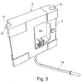
- the coupler body has in a central portion between its provided at opposite ends coupling and locking receptacles to be coupled to the coupling part down recess for receiving and / or retracting hydraulic connections of the coupler part to be coupled, wherein the actuating mechanism for manually actuating the at least one locking member in addition to said Recess, the recess is released.
- the hydraulic connections can retract into said recess between edge arranged Kuppler Modellmaschine and / or Stellgetriebeabête and thus the Kupplerkorpus be driven without collision on the coupler part to be coupled.
- the quick coupler can continue to be used for hydraulic coupler solutions, as in this case said recess in the coupler body simply remains free, if no hydraulic or power circuit couplings are provided on the counterpart.
- Said recess may in this case form a cup-shaped or trough-shaped depression in the underside of the coupler body, ie in the coupler body side which is driven onto the coupling part to be coupled when coupling, wherein said cup-shaped or trough-shaped depression is made sufficiently deep to accommodate the hydraulics - To record or power circuit clutches on the dome part to be coupled.
- the said recess can at the edge of stiffening and / or strength-increasing structure thickening and / or edge beads and / or adjusting gear sections of the manually operable Adjusted or enclosed actuating gear, wherein such structure thickening or edge beads may advantageously be provided on at least two or three edge sides of said recess.
- said structural thickenings or edge thickenings may extend along the side edges of the coupler body, while the central region of the coupler body is recessed from such structural thickenings and / or may be formed by a flat, thin plate or a similarly thin structural sheet or part.
- the aforementioned adjusting gear sections can also be arranged at least partially within said edge-bordering structural thickenings and / or edge beads.
- said central recess may be at least partially formed as a through-hole, so that in the coupler body, a central through-hole is provided with a free visual axis therethrough.
- Said through-passage can pass centrally through the coupler body and extend from the underside of the coupler body, which is intended to be driven onto the counterpart or coupler part to be coupled, up to its upper side.
- the coupler part possibly present on the coupler part which may be present remain accessible even when the coupler is coupled, from above or through the said passage recess.
- the quick coupler regardless of the height of possibly existing hydraulic couplings can be built very flat.
- Said recess in the coupler body may vary in size, wherein it is dimensioned sufficiently large in each case to accommodate the present at the counterpart hydraulic or power circuit clutches.
- said recess can advantageously in the transverse direction - ie transverse to the adjusting axis of the locking element and / or transversely to the plane of the coupling movement and / or parallel to the bolt-shaped locking parts of the coupling part to be coupled - a clear width of more than 50% or more than 66% of the width of the entire coupler body possess.
- the recess can advantageously a clear width or length of at least more than 33% or more than 50% of the spacing of the coupling and locking receptacles, wherein also a length more than 66% of said spacing is possible.
- the actuating mechanism laid next to said recess may, in an advantageous embodiment of the invention, comprise a rotatably mounted rotary actuator which, by turning over an actuating link, displaces the locking element with which the locking receptacle is closed or the locking part received therein is locked.
- a spring device can be coupled with said rotary actuator part, in particular in such a way that upon rotation of the rotary actuator part a dead center is run over and the rotary actuator part can be prestressed by the spring device into opposite end positions which can correspond to the locked and unlocked positions of the coupler.
- the spring device is more relaxed in both end positions of the rotary actuator than in the intermediate dead center position, so that the spring device can hold the actuating gear both in the unlocked position and in the locked position by spring force. In order to move from the unlocked position to the locked position or vice versa from the locked to the unlocked position, manually said spring force must be overcome.
- the said spring means on the one hand and the actuating link on the other hand which converts the rotational movement of the rotary actuator into an actuating movement of the locking element, be arranged on different or opposite sides of the locking part.
- said assembly comprising the rotary actuator, the actuating arm and the spring device can extend laterally along the coupler body and / or along said recess, without the assembly, the recess and the retractability of the hydraulic couplings in the Obstruct or restrict the area of the recess.
- said assembly can be made relatively long or take advantage of a large part of the available length of the coupler body, whereby a favorable leverage and a simple design spring means can be provided.
- the said spring device can advantageously act directly on said rotary actuator part and / or bias a clamping arm, which is hinged on the one hand articulated to said rotary actuator part and on the other hand slidably guided on the Kupplerkorpus.
- the spring means may be associated with said biasing link such that said biasing link is biased along its longitudinal direction and is being urged against the pincer body by the spring force.
- the quick coupler may comprise two locking elements, which are associated with said locking receptacle and can lock a locking member received therein.
- each of said locking elements is a separate Stellgetriebebaueria each comprising a rotary actuator, associated with an articulated actuation link and a spring device, wherein said adjusting gear assemblies advantageously laterally to opposite Can extend edges of the coupler body and / or on opposite sides of the aforementioned recess.
- the two Stellgetriebebau phenomenon can be synchronized by a synchronization shaft, which connects the two Wheelberichtile each other and synchronized in terms of their rotation.
- a rotational synchronization of the two rotary actuator parts and thus the locking movement of the locking elements can also be achieved by the actuation tool to be applied, which can replace or have, for example, said synchronization shaft.
- the hand tool can be inserted from one side into both rotary actuator parts, for example via a polygonal recess and / or a splined recess and / or an otherwise torque-transmitting recess in the two rotary actuator parts.
- the two adjusting gear assemblies can therefore also be synchronized by the hand tool to be used, so that even more installation space for the coupling movement is available when the operating tool is removed.
- the two actuating gearing assemblies mentioned can also be actuated via separate actuating tools.
- the at least one rotary actuator can be positioned on the coupler body such that the axis of rotation of the rotary actuator is aligned with a recess which is provided in a side flange of the coupling part to be coupled, so that said axis of rotation of the rotary actuator in the contracted or coupled state is in a range bounded by side flanges of the coupler part to be coupled.
- the axis of rotation of the rotary actuator parts moves into an inner space between the side flanges of the coupler part to be coupled, whereby a particularly flat construction of the quick coupler is made possible.
- the rotary actuator is positioned so that its axis of rotation is aligned, in the coupled state, with a through-hole provided in said side flange of the coupling member to be coupled.
- the actuation tool to be applied can thus be inserted through the said passage recess in the side flange and brought into engagement with the rotary actuator part.
- said drive shaft can be operated not only manually by coupling a hand tool, but the quick coupler can include a drive or a foreign energy operable Stellaktor to rotate the drive shaft by means of external energy and thus the locking and securing element and extend to be able to.
- the common drive shaft may for this purpose have a Stellaktoran gleich for connecting such a Stellaktors for rotating the drive shaft, wherein said Stellaktoran gleich can be provided, for example, on one of the aforementioned rotary actuator or on another rotary actuator which is rotatably connected to the drive shaft.
- Stellaktor can basically be designed differently.
- a pressure medium cylinder may be provided, which is hydraulically or optionally also pneumatically actuated.
- a Stellaktor may extend substantially parallel to a connection plane which passes through the locking recess and the Ankuppelfact, said Stellaktor can be aligned with its longitudinal and / or effective axis advantageously substantially perpendicular to the longitudinal axis of the drive shaft.
- the Stellaktor may also have an electric motor and / or an electric Stellaktor.
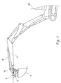
- Fig. 1 shows, the quick coupler 1 between the free end of the boom 5 of an excavator 30 and the tool to be mounted on it 4 are mounted, said attachment tool 4 in Fig. 1 is designed as a grave spoon, but in a conventional manner, of course, other corresponding construction, handling or demolition tools, for example in the form of clamshell, demolition tongs, scissors or the like may include.
- Said quick coupler 1 is in this case on the one hand by means of a handle-side coupler part 2 pivotally mounted to a lying, aligned transversely to the longitudinal axis of the boom stem 5 pivot axis of said boom arm 5, so that the quick coupler 1 together with the attached tool 4, for example by means of a pressure medium cylinder 36 and an intermediate swivel piece 37 can be pivoted relative to the extension arm 5.
- said quick coupler can be mounted on the attachment tool 4 and / or an intermediate rotary drive.
- a locking receptacle 10 include the two Locking parts, for example in the form of locking axes 13 and 14 on the other, preferably tool-side coupler part 3 hooked or can be brought into engagement.
- FIG. 2 shows the Ankuppelage 6 and the locking receptacle 10 each have a mouth-shaped, open to one side receptacle into which the locking axles 13 and 14 can retract, which may be formed by transverse bolts or locking bolts, see.
- Fig. 2 shows the Ankuppelage 6 and the locking receptacle 10 each have a mouth-shaped, open to one side receptacle into which the locking axles 13 and 14 can retract, which may be formed by transverse bolts or locking bolts, see.
- Fig. 2 shows the Ankuppelage 6 and the locking receptacle 10 each have a mouth-shaped, open to one side receptacle into which the locking axles 13 and 14 can retract, which may be formed by transverse bolts or locking bolts, see.
- Fig. 2 shows the Ankuppelage 6 and the locking receptacle 10 each have a mouth-shaped, open to one side receptacle into which the locking axles 13 and 14 can retract, which
- the Ankuppelage 6 and the locking receptacle 10 are advantageously arranged and configured such that when a first locking axle 13 of a coupler part 3 is retracted or hooked into the preferably hook-shaped Ankuppelage 6 of the other coupler part 2, the two coupler parts can be pivoted to each other in such a way that the Ankuppelage 6 and the locking shaft 13 received therein form the axis of rotation and can retract the second locking shaft 14 in the locking receptacle 10 by the corresponding pivoting movement, so that the two coupler parts 2 and 3 are coupled together in a two-stage coupling process can.
- the Ankuppelage 6 is hooked to the first locking shaft 13 to then by pivoting the two coupler parts 2 and 3 relative to each other - which can be done for example by actuation of the aforementioned pivoting cylinder 36 - the locking receptacle 10 can be brought into engagement with the second locking axis 14.
- a locking element 11 is provided, for example in the form of a locking wedge, which can be moved on the opening side of the locking receptacle 10 in front of the locking shaft 14 received therein, cf. Fig. 3 ,
- a tool 15 can advantageously be attached.
- the coupling receptacle 6 is advantageously associated with a securing element 25 which secures or locks the locking axis 13 in the coupling receptacle 6 and prevents the locking axis 13 from being moved out of the coupling receptacle 6.
- Said securing element 25 may comprise a movable latch part which can be retracted into the area of the open end of the coupling receptacle 6, cf. Fig. 6 (b) ,
- two locking elements 11 of the locking receptacle 10 are advantageously assigned to lock therein the second locking axis 14, wherein said locking elements 11 may be advantageously arranged on opposite edge or side portions of the coupler body 7.
- two securing elements 25 may be associated with the coupling receptacle 6 in order to lock the first locking axis 14 therein, wherein said securing elements 25 may advantageously be arranged on opposite edge or side sections of the coupler body 7.
- the two locking elements 11 and the two securing elements 25 can advantageously be manually operated via a control gear 12, wherein each locking element 11 and securing element 25 may be assigned its own adjusting gear assembly, which can be synchronized with each other via the tool 15 to be applied or a synchronization shaft.
- each adjusting gear assembly of the adjusting gear 12 includes a rotary actuator 16 which is mounted about a transverse axis approximately parallel to the longitudinal extent of the locking receptacle 10 and transversely to the longitudinal axis of the locking member 11 rotatably mounted on the coupler body 11, wherein advantageously the axes of rotation of the two rotary actuator parts 16 to each other can be aligned.
- an actuating link 17 is articulated, which, on the other hand, is articulated on the associated locking element 11. If the rotary actuator 16 is rotated, the said actuating link 17 converts the rotational movement into a displacement of the locking element 11.
- the said locking element 11 is for this purpose mounted longitudinally displaceable on the coupler body 7.
- a second rotary setting part 26 can be provided, which can be formed separately from the first rotary setting part 16, but can also be combined with the mentioned rotary setting part 16.
- An actuation link 27 directs the securing element 25 against the aforementioned rotary setting part 26 in order to convert a rotation of the rotary setting part 16 into a translatory sliding movement of the securing element 25.
- the rotary actuator parts 16 and 26 extend on opposite sides of the axis of rotation, so that the locking and securing elements 11 and 25 are moved in opposite directions to each other when the rotary actuator parts are rotated in one direction of rotation, see. in comparison to each other Fig. 6 (a) and Fig. 6 (b) ,
- a tension link 18 is articulated articulated to said rotary actuator 16 and / or the rotary actuator 26, on the other hand, is displaceably guided on the coupler body 7. More precisely, the said tension control arm 18 is slidably guided on a rotatable stop 19, so that the tension link 18 can be displaced against the stop 19 during rotational movements of the rotary actuating part 16, wherein the stop 19 can rotate simultaneously in order to take into account the pivoting of the tension link 18 ,
- Said tensioning arm 18 is prestressed by a spring device 20, said spring device 20 being able to be arranged between said stop 19 and a shoulder of the tensioning link 18, for example in the form of a helical spring which is pushed over the tensioning link 18.
- the clamping force of the spring device 20 attempts to move the tension link 18 in one direction, which causes a rotational bias on the rotary actuator 16 and / or the rotary actuator 26.
- the spring device 20 and the tensioning link 18 are in this case arranged on the rotary adjusting part 16 that when turning the rotary actuator 16 from the unlocked position into the locking position and vice versa from the locking position to the unlocked position a dead center position is run over and the spring device 20, the rotary actuator 16 once trying to bias in one direction and the other in the other direction.
- the spring device 20 biases the rotary actuator 16 on the one hand the unlocked end position and on the other hand in the locked end position before, depending on which side of the said dead center has been run over.
- the spring device 20 and the tension link 18 on the one hand and the actuating link 17 on the other hand on opposite sides of the rotary actuator 16 are arranged to achieve an overall very slim design of the adjusting gear assemblies.
- the two Stellgetriebebau phenomenon can be synchronized by a drive or synchronization shaft 21 with each other, which couples the two rotary actuator members 16 together so that they are rotated in synchronization with each other.
- Said drive shaft 21 can be permanently installed or alternatively be formed by the actuation tool 15 to be attached, which can be inserted from one side in both rotary actuator parts 16 and 26 respectively.
- the rotary actuator parts 16 and 26 can for this purpose have a torque-transmitting plug-in recess, for example in the form of a polygonal hole or a profile shaft recess.
- the rotary actuator parts 16 and 26 can advantageously be arranged such that the actuating tool 15 can be inserted through a through-passage 22 which can be inserted into one of the side flanges of the coupler part 3 to be coupled, cf. Fig. 2 ,
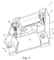
- FIGS. 4 and 5 show the coupler body 7 of the coupler part 2 has a central recess 8 which is provided between the Ankuppel- and locking receptacles 6 and 10 and extends on the underside of the coupler body 7, see.
- FIGS. 4 and 5 show the coupler body 7 of the coupler part 2 has a central recess 8 which is provided between the Ankuppel- and locking receptacles 6 and 10 and extends on the underside of the coupler body 7, see.
- FIGS. 4 and 5 show the coupler body 7 of the coupler part 2 has a central recess 8 which is provided between the Ankuppel- and locking receptacles 6 and 10 and extends on the underside of the coupler body 7, see.
- FIGS. 4 and 5 show the coupler body 7 of the coupler part 2 has a central recess 8 which is provided between the Ankuppel- and locking receptacles 6 and 10 and extends on the underside of the coupler body 7, see.
- Said recess 8 is thereby framed, on the one hand by said coupling and locking receptacles 6 and 10 and the sections of the coupler body 7 forming these, and on the other hand by longitudinally extending longitudinal webs which form the coupler body 7 on the right and on the left connect both Ankuppel- and locking receptacles 6 and 10 together.
- the central region of the coupler body 7 is thus recessed, said recess 8 can extend over more than two thirds of the width of the coupler body 7 and over at least half of the length in the sense of spacing between the two Ankuppel- and locking receptacles 6 and 10.
- said recess 8 may form a central cup-shaped or trough-shaped recess in the underside of the coupler body 7, which is moved to the coupler part 3 to be joined during coupling, said recess 8 laterally to the right and left of strengthening, stiffening structure thickening, in particular in the form may be bordered by edge beads 23.
- Said edge beads 23 may form an elongate hollow box profile or else consist of a solid longitudinal member or web, so that the thickness of the coupler body on the lateral edge beads 23 increases massively with respect to the recessed central region and in particular is a multiple of the thickness in the central region.
- FIG. 5 show the central recess 8 can be bordered along three sides of such edge beads, wherein left and right arranged edge beads 23l and 23r be at least partially formed as a hollow box profile and / or can accommodate the adjusting gear sections of the adjusting gear 12.
- a transversely extending edge bead 23q can form the receiving jaw 6 and / or laterally shaped peripheral mouthpieces 6 connect together and be formed, for example in the form of a solid half-shell profile.
- a structural plate 24 for example in the form of a sheet metal plate, in particular sheet steel plate or a thin, approximately planar structural part, which may also be designed wandwerk- or net or mesh-like.
- a central through-hole 8a may be provided, which may form part of said recess 8 and in the area of said recess 8 extends from the bottom to the top of the coupler body 7.
- Said passage recess 8a may, for example, have an extent whose inside diameter is more than 50% or even more than 66% of the width of the entire coupler body and / or its clear length more than 33% or even more than 50% of the spacing of the coupling and Locking recordings is.
- the actuating mechanism 12 extends laterally to the right and left of said recess 8 and leaves the said recess 8 free, so that existing coupling coupler 3 existing hydraulic couplings 9 collision-free retract into the recess 8 and between the two Ankuppel- and locking receptacles 6 and 10th can retract.
- Said actuating gear 12 may extend at least partially in the interior of said edge-side edge beads 23l and 23r, wherein alternatively or additionally said edge beads 23 may also have recesses in the region of which said actuating gears 12 are exposed.
- the quick coupler is advantageously characterized by the fact that both the locking receptacle 10 associated locking member 11 and a movable securing member 25 which is associated with the Ankuppelfact 6 for securing the first locking member 13 received therein, actuated by the common drive shaft 21 and each over an actuating handlebars 17, 27 are articulated on a rotatably connected to the common drive shaft 21 rotary actuator part 16, 26, so that the Verriegelungslement 11 and the securing element 25 by rotating the common drive shaft 21 in a rotational direction to each other in opposite directions.
- said drive shaft 21 extends transversely over the coupler body 7 between the coupling receptacle 6 and the locking receptacle 10 and a side wall 7s of the coupler body 7 has a through-passage 28, through which the drive shaft 21 extends to an outer side of the coupler body 7 extends and / or the hand tool with the drive shaft 21 can be coupled.
- the Ankuppelage 6 forms a mouth-shaped blind groove with a NutlCodesachse 29, which is facing away from the locking receptacle 10 to a side, wherein the NutlHarsachse 29 to a control axis 25a of the fuse element 25 and / or a connecting plane 30 which goes through both the Ankuppelage 6 and through the locking receptacle 10 is inclined at an acute angle.
- the rotary actuator parts 16, 26, on which the locking element 11 on the one hand and the securing element 25 are hinged on the other hand extend on opposite sides of the drive shaft 11 and are arranged such that the actuating links 17, 27 of the locking element 11 and When the drive shaft 21 is rotated, the securing element 25 can be overstretched from the unlocking position into the locking position and in each case run over a dead center.
- the quick coupler can be characterized in that the securing element 25 is coupled via the operating link 27 and the rotary actuator 26 at least substantially free of play to the rotational movement of the drive shaft 21 and the rotational movement of the drive shaft 21 is positively controlled converted into an actuating movement of the securing element 25 while the locking member 11 relative to the drive shaft 21 has a limited clearance, which is preferably associated with a biasing device for biasing in an end position of clearance.
- a monitoring sensor system 31 for monitoring the locking has at least one rotary position sensor 32 for monitoring the reaching of an interlocking rotational position of the drive shaft 21 and two pick-up sensors 33, 34, which are assigned on the one hand the Ankuppelage 6 and on the other hand, the locking receptacle 10 and the presence the first and second locking part 13, 14 in the Ankuppelage 6 and the locking receptacle 10 monitor.
- the common drive shaft 21 has a Stellaktoran gleich for connecting a foreign energy actuated Stellaktors 35 for rotating the drive shaft 21.
- the quick coupler can be characterized in that the Stellaktor 35 includes at least one pressure medium cylinder 36 which extends substantially parallel to a connection plane which goes through both the Ankuppelage 6 and through the locking receptacle 10.
- the quick coupler can be characterized in that the Stellaktor 35 includes an electric motor and / or an electric Stellaktor.
Abstract
Die vorliegende Erfindung betrifft einen Schnellkuppler zum Ankuppeln eines Werkzeugs wie beispielsweise Baggerlöffel, Schalengreifer oder Abbruchzangen an einen Werkzeugführer wie beispielsweise Baggerstiel oder dergleichen, mit einem Kupplerkorpus, der an gegenüberliegenden Stirnseiten einerseits eine Ankuppelaufnahme zum Aufnehmen eines ersten Verriegelungsteils eines anzukuppelnden Kupplerteils und andererseits eine Verriegelungsaufnahme zum Aufnehmen eines zweiten Verriegelungsteils des anzukuppelnden Kupplerteils aufweist, wobei zumindest der Verriegelungsaufnahme zumindest ein bewegliches Verriegelungsteil zum Verriegeln des zweiten Verriegelungsteils zugeordnet ist, wobei das genannte Verriegelungselement über ein an dem Kupplerkorpus angeordnetes Stellgetriebe manuell betätigbar ist. Erfindungsgemäß ist sowohl das der Verriegelungsaufnahme zugeordnete Verriegelungselement als auch ein bewegliches, zusätzliches Sicherungslement, das der Ankuppelaufnahme zum Sichern des darin aufgenommenen ersten Verriegelungsteils zugeordnet ist, durch die gemeinsame Antriebswelle betätigbar und jeweils über einen Betätigungslenker an einem mit der gemeinsamen Antriebswelle drehfest verbundenen Drehstellteil angelenkt, sodass das Verriegelungslement und das Sicherungselement durch Verdrehen der gemeinsamen Antriebswelle in eine Drehrichtung zueinander gegenläufig verfahren.The present invention relates to a quick coupler for coupling a tool such as excavator buckets, claw grippers or demolition tongs to a tool guide such as excavator handle or the like, with a coupler body having on opposite ends on the one hand a Ankuppelaufnahme for receiving a first locking part of a coupler part to be coupled and on the other hand a locking receptacle for Receiving a second locking part of the coupling part to be coupled, wherein at least the locking receptacle is associated with at least one movable locking part for locking the second locking part, wherein said locking element is manually operable via a arranged on the coupler body actuating mechanism. According to the invention, the locking element associated with the locking element and a movable, additional Sicherungslement that is associated with the Ankuppelaufnahme for securing the first locking member therein, actuated by the common drive shaft and each articulated via an actuating link on a rotatably connected to the common drive shaft rotary actuator part, so that the Verriegelungslement and the securing element by rotating the common drive shaft in a rotational direction to each other in opposite directions.
Description
Die vorliegende Erfindung betrifft einen Schnellkuppler zum Ankuppeln eines Werkzeugs wie beispielsweise Baggerlöffel, Schalengreifer oder Abbruchzangen an einen Werkzeugführer wie beispielsweise Baggerstiel oder dergleichen, mit einem Kupplerkorpus, der an gegenüberliegenden Stirnseiten einerseits eine Ankuppelaufnahme zum Aufnehmen eines ersten Verriegelungsteils eines anzukuppelnden Kupplerteils und andererseits eine Verriegelungsaufnahme zum Aufnehmen eines zweiten Verriegelungsteils des anzukuppelnden Kupplerteils aufweist, wobei zumindest der Verriegelungsaufnahme zumindest ein bewegliches Verriegelungsteil zum Verriegeln des zweiten Verriegelungsteils zugeordnet ist, wobei das genannte Verriegelungselement über ein an dem Kupplerkorpus angeordnetes Stellgetriebe manuell betätigbar ist.The present invention relates to a quick coupler for coupling a tool such as excavator buckets, claw grippers or demolition tongs to a tool guide such as excavator handle or the like, with a coupler body having on opposite ends on the one hand a Ankuppelaufnahme for receiving a first locking part of a coupler part to be coupled and on the other hand a locking receptacle for Receiving a second locking part of the coupling part to be coupled, wherein at least the locking receptacle is associated with at least one movable locking part for locking the second locking part, wherein said locking element is manually operable via a arranged on the coupler body actuating mechanism.
An Baumaschinen wie beispielsweise Hydraulikbaggern oder Gelenkgreifern wie beispielsweise Holzhandhabungsmaschinen oder Abbruchgeräten oder ähnlichen Materialumschlagmaschinen werden häufig Schnellkuppler zum Ankuppeln verschiedener Werkzeuge wie beispielsweise Räumlöffel, Schalengreifer oder Abbruchzangen an einen Baggerstiel oder ähnliche Werkzeugführer wie Knickarmauslegern verwendet, um verschiedene Werkzeuge ohne lange Umrüstzeiten verwenden zu können.On construction machines such as hydraulic excavators or articulated grabs such as wood handling machines or demolition equipment or similar material handling machines are often quick coupler for coupling various tools such as tedding spoons, claw grabs or demolition tongs on a bagger handle or similar tool guides such Knuckle boom used to use different tools without long changeover times can.
Derartige Schnellkuppler können als Verriegelungselemente insbesondere zwei voneinander beabstandete Verriegelungsachsen an einem Kupplungsteil aufweisen, während der andere Kupplungsteil, insbesondere der baggerstielseitige Kupplungsteil eine vorzugsweise hakenförmige Ankuppelaufnahme zum Einhaken an einer ersten der beiden Verriegelungsachsen und eine Verriegelungsaufnahme zum Verriegeln an der zweiten Verriegelungsachse aufweisen kann. Nach Einhaken der ersten Verriegelungsachse in der Ankuppelaufnahme können die beiden Kupplungsteile zueinander verschwenkt werden, wobei die in der Ankuppelaufnahme sitzende Verriegelungsachse die Drehachse bildet, so dass die zweite Verriegelungsachse in die Verriegelungsaufnahme einfährt bzw. hineingeschwenkt wird, wo die genannte zweite Verriegelungsachse dann durch ein Verriegelungselement wie beispielsweise einen ausfahrbaren Keil verriegelt werden kann, so dass es gleichzeitig auch nicht mehr möglich ist, die erste Verriegelungsachse aus der Ankuppelaufnahme herauszubewegen. Zum Verfahren des genannten Verriegelungselements ist ein fremdenergiebetätigter Stellaktor vorgesehen, der beispielsweise als Hydraulikzylinder ausgebildet sein kann und üblicherweise durch Hydraulikdruck vom Gerät her betätigbar ist.Such quick coupler can have as locking elements in particular two spaced apart locking axes on a coupling part, while the other coupling part, in particular the handlebar side coupling part may have a preferably hook-shaped coupling receptacle for hooking on a first of the two locking axes and a locking receptacle for locking on the second locking axis. After hooking the first locking axis in the Ankuppelaufnahme the two coupling parts can be pivoted to each other, wherein the seated in the Ankuppelaufnahme locking axis forms the axis of rotation, so that the second locking axis retracts into the locking receptacle or is pivoted into, where said second locking axis then by a locking element such as an extendable wedge can be locked, so that at the same time it is no longer possible to move the first locking axle from the Ankuppelaufnahme. For the operation of said locking element, a third-party actuated actuating actuator is provided, which may be designed, for example, as a hydraulic cylinder and is usually actuatable by hydraulic pressure from the device.
Die genannten Verriegelungsachsen an dem einen Kupplungsteil können dabei von Verriegelungsbolzen gebildet werden, die sich am entsprechenden Kupplungsteil insbesondere parallel zueinander erstrecken können, wobei anstelle solcher Bolzen jedoch ggf. auch andere Strukturteile des Kupplungsteils wie beispielsweise vorspringende Nasen, Achsschenkel, Eingriffsstumpfe in Form von Vorsprüngen oder Ausnehmungen beispielsweise in Form von Taschen als Verriegelungsteil dienen können, die an die Ankuppelaufnahme bzw. die Verriegelungsaufnahme des anderen Kupplungsteils formangepasst sind.The said locking axes on the one coupling part can thereby be formed by locking bolts, which may extend in particular parallel to each other on the corresponding coupling part, but instead of such bolts but possibly other structural parts of the coupling part such as projecting lugs, stub axles, engagement stumps in the form of projections or Recesses, for example in the form of pockets can serve as a locking part, which are adapted to the Ankuppelaufnahme or the locking receptacle of the other coupling part.
Solche Schnellkuppler sind von den Abmessungen und den Verriegelungsteilen her auch Gegenstand von Normen, um die Kompatibilität einer am Baggerstiel verwendeten Kupplerhälfte mit diversen Werkzeugen zu gewährleisten, an denen eine Kupplerhälfte montiert ist, die je nach Werkzeug von verschiedenen Herstellern stammen kann und soweit mit der stielseitigen Kupplerhälfte kompatibel sein muss, dass die beiden Kupplerhälften zusammenfahren und verriegeln können. Eine solche Normung ist beispielsweise in Form des sog. S-Kupplers bzw. des S-Standards erfolgt, der die Abmessungen und Anordnung der Verriegelungselemente und Aufnahmemäuler festschreibt und vom schwedischen Institut Maskinleverantörerna festgelegt wurde und zuletzt am 28.05.2010 herausgegeben wurde. Dieser S-Kuppler besitzt in der oben beschriebenen Weise an der einen Kupplerhälfte zwei parallele, voneinander beabstandete Querbolzen als Verriegelungsteile, während die andere Kupplerhälfte an gegenüberliegenden Stirnseiten einerseits eine maulförmige Ankoppelaufnahme und andererseits eine L-förmige Verriegelungsaufnahme besitzt, die durch ein Paar ausfahrbare Verriegelungsbolzen verschlossen bzw. zu einer dann ebenfalls U-förmigen bzw. maulförmigen Aufnahme geschlossen werden kann.Such quick couplers are also the subject of standards in terms of dimensions and locking parts, in order to ensure compatibility with the excavator handle used coupler half with various tools on which a coupler half is mounted, which may come from different manufacturers depending on the tool and as far as the stalk coupler half must be compatible so that the two coupler halves can move together and lock. Such standardization is carried out, for example, in the form of the so-called S-coupler or the S-standard, which stipulates the dimensions and arrangement of the locking elements and receiving jaws and was defined by the Swedish Maskinleverantörerna Institute and was last issued on 28.05.2010. This S-coupler has in the manner described above on one coupler half two parallel, spaced-apart cross bolt as locking parts, while the other coupler half has on opposite ends on the one hand a muzzle Ankoppelaufnahme and on the other hand, an L-shaped locking receptacle which closed by a pair of extendable locking bolt or to a then also U-shaped or mouth-shaped receptacle can be closed.
Weiterhin zeigt die Schrift
Weitere Beispiele solcher Schnellkuppler sind aus den Schriften
Moderne Varianten solcher Schnellkuppler sind dabei häufig hydraulisch betätigbar. Den Verriegelungselementen sind hydraulische Stellaktoren beispielsweise in Form von Hydraulikzylindern zugeordnet, mittels derer die Verriegelungselemente ein- und ausgefahren werden können. Sind dabei hydraulisch betätigbare Werkzeuge anzukuppeln, besitzen die Kupplerhälften darüber hinaus Hydraulikkupplungen, die beim Zusammenschwenken der beiden Kupplerhälften automatisch zusammenfahren.Modern variants of such quick couplers are often hydraulically actuated. The locking elements are associated with hydraulic actuators, for example in the form of hydraulic cylinders, by means of which the locking elements can be retracted and extended. Are there hydraulically actuated tools to couple, the coupler halves also have hydraulic clutches, the automatically collapse when swinging the two coupler halves together.
Es werden jedoch immer noch manuell betätigbare Kupplerhälften benötigt, insbesondere in kleineren Betrieben oder für selten benutzte Maschinen, für die sich vollhydraulische Schnellwechslersysteme nicht lohnen bzw. zu kostspielig sind.However, manually operable coupler halves are still needed, especially in smaller operations or for infrequently used machines for which fully hydraulic quick coupler systems are not worthwhile or too costly.
Solche manuell betätigbaren Schnellkuppler besitzen dabei üblicherweise ein Stellgetriebe, das an dem Kupplerkorpus angeordnet ist, an dem die genannten Verriegelungselemente ein- und ausfahrbar bzw. in anderer Weise zwischen Verriegelungs- und Entriegelungsstellung bewegbar sind. Mittels solcher Stellgetriebe werden die benötigten Stellkräfte reduziert, um eine einfache händische Betätigung zu gewährleisten. Beispielsweise kann ein Hebelmechanismus vorgesehen sein, der durch einen verdrehbaren Drehstellteil betätigt werden kann, so dass über die Hebelverhältnisse eine günstige manuelle Betätigung erzielt werden kann. Dabei kann ein Schraubenschlüssel oder ein ähnliches Werkzeug, wie es in vergleichbarer Form für das Lösen und Anziehen der Radmuttern beim Radwechsel an einem Kraftfahrzeug bekannt ist, lösbar an den genannten Drehstellteil angesetzt werden, beispielsweise über eine Mehrkantsteckverbindung, um den Drehstellteil zu betätigen. Ein solches Stellgetriebe umfasst dabei sinnvollerweise auch eine Feder, die das Verriegelungselement vorspannt.Such manually operable quick couplers usually have a control gear which is arranged on the coupler body, on which the said locking elements can be moved in and out or in another way between locking and unlocking position. By means of such adjusting the required actuating forces are reduced to ensure a simple manual operation. For example, a lever mechanism may be provided which can be actuated by a rotatable rotary actuator, so that a favorable manual operation can be achieved via the lever ratios. In this case, a wrench or a similar tool, as it is known in a comparable form for loosening and tightening the wheel nuts when changing the wheel on a motor vehicle, are releasably attached to said rotary actuator part, for example via a polygonal connector to actuate the rotary actuator. Such a control gear expediently also includes a spring that biases the locking element.
Aufgrund des Stellgetriebes ist es bislang jedoch schwierig, einen solchen manuell betätigbaren Schnellkuppler an Kupplerhälften anzukuppeln, an denen auch Hydraulik- und/oder Energiekreiskupplungen angeordnet sind, da das Stellgetriebe und der das Stellgetriebe umgebende Kupplerkorpus mit solchen Hydraulik- bzw. Energiekreiskupplungen kollidieren würden. Üblicherweise sind solche Hydraulik- bzw. Energiekreiskupplungen zentral zwischen den gegenüberliegenden Verriegelungsteilen angeordnet, die in die Ankuppel- und Verriegelungsaufnahmen einzufahren sind, und liegen somit exakt dort, wo an der gegenüberliegenden Kupplerhälfte das genannte Stellgetriebe angeordnet ist. Im Ergebnis können bislang solche manuell betätigbaren Schnellkuppler lediglich mit Kupplerhälften gekuppelt werden, die keine solchen Hydraulik- bzw. Energiekreiskupplungen aufweisen.Due to the adjusting gear, however, it has hitherto been difficult to couple such a manually operable quick coupler to coupler halves on which hydraulic and / or energy circuit couplings are arranged, since the actuating gear and the coupler body surrounding the actuating mechanism would collide with such hydraulic or energy-circuit couplings. Usually such hydraulic or power circuit clutches are arranged centrally between the opposite locking parts, which are to be retracted into the Ankuppel- and locking receptacles, and thus lie exactly where the said actuating gear is arranged on the opposite coupler half. As a result, you can So far, such manually operable quick couplers are coupled only with coupler halves, which have no such hydraulic or power circuit clutches.
Hiervon ausgehend liegt der vorliegenden Erfindung die Aufgabe zugrunde, einen verbesserten Schnellkuppler der genannten Art zu schaffen, der Nachteile des Standes der Technik vermeidet und Letzteren in vorteilhafter Weise weiterbildet. Insbesondere soll eine sichere und gleichzeitig einfache manuelle Verriegelung bei kompakter Bauweise ermöglicht werden, auch wenn die gegenüberliegende Kupplerhälfte Hydraulik- oder andere Energiekreiskupplungen aufweist.On this basis, the present invention has the object to provide an improved quick coupler of the type mentioned, which avoids the disadvantages of the prior art and further develops the latter in an advantageous manner. In particular, a secure and at the same time simple manual locking should be made possible with a compact design, even if the opposite coupler half has hydraulic or other energy-circuit couplings.
Erfindungsgemäß wird die genannte Aufgabe durch einen Schnellkuppler gemäß Anspruch 1 gelöst. Bevorzugte Ausgestaltungen der Erfindung sind Gegenstand der abhängigen Ansprüche.According to the invention, the stated object is achieved by a quick coupler according to claim 1. Preferred embodiments of the invention are the subject of the dependent claims.
Es wird also vorgeschlagen, zusätzlich zu den Verriegelungselementen, die der Verriegelungsausnehmung zugeordnet sind, auch der Aufnahmeausnehmung zumindest ein Sicherungselement zuzuordnen, um das darin aufgenommene Verriegelungsteil zu sichern, und beide Elemente, das heißt Verriegelungslement und Sicherungselement an die gemeinsame Antriebswelle anzubinden, um mit nur einer Drehbewegung der gemeinsamen Antriebswelle sowohl die Verriegelungsals auch die Sicherungslemente verriegeln und entriegeln zu können. Erfindungsgemäß ist sowohl das der Verriegelungsaufnahme zugeordnete Verriegelungselement als auch ein bewegliches, zusätzliches Sicherungslement, das der Ankuppelaufnahme zum Sichern des darin aufgenommenen ersten Verriegelungsteils zugeordnet ist, durch die gemeinsame Antriebswelle betätigbar und jeweils über einen Betätigungslenker an einem mit der gemeinsamen Antriebswelle drehfest verbundenen Drehstellteil angelenkt, sodass das Verriegelungslement und das Sicherungselement durch Verdrehen der gemeinsamen Antriebswelle in eine Drehrichtung zueinander gegenläufig verfahren. Insbesondere verfährt das Verriegelungselement zur einen Seite des Schnellkupplerkorpus hin in die dort vorgesehene Verriegelungsaufnahme, während das Sicherungselement zur gegenüberliegenden Kupplerkorpusseite hin in die dort vorgesehene Ankuppelaufnahme fährt, wenn die gemeinsame Antriebswelle in eine Richtung verdreht wird. Wird die Antriebswelle in die entgegengesetzte Drehrichtung verdreht, fahren die Verriegelungs- und Sicherungselemente zueinander gegenläufig in ihre jeweils entriegelnde Stellung.It is therefore proposed, in addition to the locking elements, which are associated with the locking recess, and the receiving recess at least to assign a securing element to secure the locking member received therein, and to connect both elements, ie Verriegelungslement and securing element to the common drive shaft with only a rotational movement of the common drive shaft to lock and unlock both the Verriegelungsals and the Sicherungslemente can. According to the invention, the locking element associated with the locking element and a movable, additional Sicherungslement that is associated with the Ankuppelaufnahme for securing the first locking member therein, actuated by the common drive shaft and each articulated via an actuating link on a rotatably connected to the common drive shaft rotary actuator part, so that the Verriegelungslement and the securing element by rotating the common drive shaft in a rotational direction to each other in opposite directions. In particular, the locking element moves toward one side of the quick-release body in the locking receptacle provided there, while the fuse element moves towards the opposite side of the coupler body in the Ankuppelaufnahme provided there, when the common drive shaft is rotated in one direction. If the drive shaft is rotated in the opposite direction of rotation, the locking and securing elements move counter to each other in their respective unlocking position.
Vorteilhafterweise kann sich die genannte Antriebswelle zwischen der Ankuppelaufnahme und der Verriegelungsaufnahme quer über den Kupplerkorpus hinweg erstrecken, insbesondere in einer Richtung senkrecht zu den Verstellrichtungen der Verriegelungs- und Sicherungelemente, wobei vorteilhafterweise in einer Seitenwange des Kupplerkorpus eine Durchgangsausnehmung vorgesehen sein kann, durch die hindurch sich die Antriebswelle zu einer Außenseite des Kupplerkorpus hin erstrecken kann, um dort mit einem Handwerkzeug gekuppelt zu werden. Alternativ kann auch das Handwerkzeug durch die genannte Durchgangsausnehmung hindurchgesteckt werden, um in der genannten Seitenwange oder auch innerhalb der genannten Seitenwange mit der Antriebswelle gekuppelt zu werden.Advantageously, said drive shaft may extend transversely across the coupler body between the coupling receptacle and the latch receptacle, in particular in a direction perpendicular to the adjustment directions of the latching and securing elements, wherein a through-passage may advantageously be provided in a side wall of the coupler body through which passes the drive shaft may extend to an outside of the coupler body to be coupled there with a hand tool. Alternatively, the hand tool can be inserted through said passage recess to be coupled in said side cheek or within said side cheek to the drive shaft.
Das Ankuppeln des Handwerkzeugs kann dabei grundsätzlich in verschiedener Weise erfolgen. Beispielsweise kann das Handwerkzeug mittels einer Welle-Nabe-Verbindung drehfest auf die Antriebswelle aufgesteckt werden, sodass sich das Handwerkzeug und die Antriebswelle näherungsweise koaxial zueinander erstrecken. Alternativ können das Handwerkzeug und die Antriebswelle aber auch zueinander versetzt angeordnet werden, beispielsweise indem ein Ritzel drehfest an der Antriebswelle und ein Ritzel drehfest am Handwerkzeug vorgesehen werden und im Sinne einer Stirnradstufe ineinandergreifen können. Alternativ oder zusätzlich zu einer solchen Stirnradstufe kann zwischen das Handwerkzeug und die Antriebswelle am Kupplerkorpus auch eine Kegelradstufe geschaltet sein, um die Drehachse des Handwerkzeugs gegenüber der Drehachse der Antriebswelle zu verkippen bzw. abzuknicken. Gleichzeitig kann durch eine solche Ritzel- bzw. Getriebestufe eine Untersetzung bzw. Übersetzung zwischen Handwerkzeug und Antriebswelle erzeugt werden, die ein besonders kraftsparendes, leichtgängies Betätigen des Schnellkupplers ermöglicht.The coupling of the hand tool can basically be done in various ways. For example, the hand tool by means of a shaft-hub connection rotatably mounted on the drive shaft, so that the hand tool and the drive shaft extend approximately coaxially to each other. Alternatively, the hand tool and the drive shaft but can also be arranged offset from each other, for example by a pinion rotatably on the drive shaft and a pinion rotatably provided on the hand tool and can interlock in the sense of a spur gear. As an alternative or in addition to such a spur gear stage, a bevel gear stage can also be connected between the hand tool and the drive shaft on the pakker body in order to tilt or bend the axis of rotation of the hand tool relative to the axis of rotation of the drive shaft. At the same time by such a pinion or gear stage, a reduction or translation between hand tool and Drive shaft can be generated, which allows a particularly power-saving, leichtgängies operating the quick coupler.
In vorteilhafter Weiterbildung der Erfindung kann das zusätzliche Sicherungselement schräg und/oder spitzwinklig in die Ankuppelaufnahme hineingefahren werden, um das dort befindliche Verriegelungsteil formschlüssig am Herausrutschen aus der Ankuppelaufnahme zu hindern. Insbesondere kann die genannte Ankuppelaufnahme eine maulförmige Sacknut mit einer Nutlängsachse bilden, die zu einer Seite des Kupplerkorpus hin, die von der Verriegelungsaufnahme abgewandt ist, offen ist, wobei sich die Ankuppelaufnahme mit ihrer genannten Nutlängsachse zu einer Stellachse des Sicherungselements und/oder zu einer Verbindungsebene, die sowohl durch die Ankuppelaufnahme als auch durch die Verriegelungsaufnahme geht, spitzwinklig geneigt erstrecken kann. Betrachtet man den näherungsweise beispielsweise quaderförmigen Kupplungskorpus in einer horizontal ausgerichteten Stellung, kann sich die genannte Ankuppelaufnahme beispielsweise spitzwinklig schräg nach oben geneigt und/oder spitzwinklig schräg nach unten geneigt erstrecken, wobei das Sicherungselement im Wesentlichen horizontal verfahren und teilweise in die Ankuppelaufnahme hinein verfahren werden kann, um den Ein- und Ausführweg für das zugehörige Verriegelungsteil zu versperren.In an advantageous embodiment of the invention, the additional securing element can be moved into the Ankuppelaufnahme obliquely and / or acute-angled to prevent the locking member located there form-fitting on slipping out of the Ankuppelaufnahme. In particular, said coupling receptacle can form a mouth-shaped blind groove with a groove longitudinal axis, which is open to one side of the coupler body, which faces away from the locking receptacle, wherein the Ankuppelaufnahme with its said groove longitudinal axis to a control axis of the fuse element and / or to a connection plane , which goes through both the Ankuppelaufnahme and through the locking receptacle, can extend at an acute angle inclined. Considering the approximately, for example, cuboid coupling body in a horizontally oriented position, said Ankuppelaufnahme may, for example, angled at an acute angle obliquely upwards and / or obliquely obliquely downwards inclined, the securing element substantially horizontally moved and can be partially moved into the Ankuppelaufnahme inside to block the entry and exit path for the associated locking part.
Vorteilhafterweise kann auch das Verriegelungslement im Wesentlichen horizontal verfahren werden, wenn der besagte quaderförmige Kupplungskorpus in einer horizontalen Stellung betrachtet wird. In diesem Fall können das Verriegelungselement und das Sicherungselement beide horizontal bzw. entlang zueinander im Wesentlichen paralleler Achsen verfahren werden, was sich günstig für die Betätigung durch die gemeinsame Antriebswelle auswirkt und gleichzeitig eine kompakte, flache Bauweise des Kupplers ermöglicht.Advantageously, the Verriegelungslement can be moved substantially horizontally, when said cuboid coupling body is considered in a horizontal position. In this case, the locking element and the securing element can both be moved horizontally or along mutually substantially parallel axes, which is favorable for the operation by the common drive shaft and at the same time enables a compact, flat construction of the coupler.
Vorteilhafterweise können sich die Drehstellteile, an denen das Verriegelungsteil einerseits und das Sicherungselement andererseits über die schon genannten Betätigungslenker angelenkt sind, auf gegenüberliegenden Seiten der Antriebswelle erstrecken und derart angeordnet sein, dass die Betätigungslenker des Verriegelungselements und des Sicherungselements beim Verdrehen des der Antriebswelle aus der entriegelnden Stellung in die verriegelnde Stellung überstreckt werden und jeweils einen Totpunkt überfahren. Durch eine solche Konfiguration, bei der die Betätigungslenker überstreckt werden und ein Totpunkt überfahren wird, kann die Antriebswelle durch Anfahren von Drehanschlägen die Verriegelungs- und Sicherungselemente sicher in der verriegelnden und entriegelnden Stellung gehalten werden, ohne dass hierfür spezielle, zusätzliche Sicherungsmaßnahmen beispielsweise in Form von Sperrriegeln erforderlich wären.Advantageously, the rotary adjusting parts, on which the locking part on the one hand and the securing element on the other hand are articulated on the already mentioned actuating link, on opposite sides of the Extend drive shaft and be arranged such that the actuating arm of the locking element and the securing element are overstretched during rotation of the drive shaft from the unlocking position to the locking position and each run over a dead center. By such a configuration in which the control arms are overstretched and a dead center is run over, the drive shaft can be safely held in the locking and unlocking position by approaching rotation stops the locking and securing elements, without requiring special, additional security measures, for example in the form of Locking bolts would be required.
Dabei können das Sicherungselement einerseits und das Verriegelungselement andererseits in unterschiedlicher Weise an die Drehbewegung der gemeinsamen Antriebswelle angebunden sein, insbesondere dergestalt, dass das Sicherungselement im Wesentlichen spielfrei, zwangsgesteuert an die Rotation der Antriebswelle gekoppelt ist, während das Verriegelungselement einen begrenzten Freigang gegenüber der Rotationsbewegung der Antriebswelle aufweist, beispielsweise durch Vorsehen einer Längsnut bzw. eines Langlochs, welches einen Anlenkpunkt des Betätigungslenkers bilden kann. Hierdurch wird es möglich, das Verriegelungselement formschlüssig auf Stoß gegen das Verriegelungslement bzw. im Sinne eines Anschlags gegen das Verriegelungselement zu fahren, auch wenn der Betätigungslenker beim Anfahren der verriegelnden Stellung überstreckt wird und den Totpunkt überfährt. Vorteilhafterweise kann dem genannten Freigang hierbei eine Vorspanneinrichtung, beispielsweise in Form einer Federeinrichtung, zugeordnet sein, um das Verriegelungselement in die kontaktierende, anschlagende Stellung am Verriegelungsteil zu fahren.In this case, the securing element on the one hand and the locking element on the other hand be connected in different ways to the rotational movement of the common drive shaft, in particular such that the securing element is substantially free of play, forcibly coupled to the rotation of the drive shaft, while the locking element a limited clearance against the rotational movement of the Drive shaft, for example, by providing a longitudinal groove or a slot, which can form a point of articulation of the actuating arm. This makes it possible to drive the locking element positively against impact against the Verriegelungslement or in the sense of a stop against the locking element, even if the actuating arm is overstretched when starting the locking position and moves over the dead center. Advantageously, the said clearance in this case a biasing device, for example in the form of a spring device, be assigned to drive the locking element in the contacting, abutting position on the locking part.
Der genannte Freigang ist hierbei relativ klein und in jedem Falle so begrenzt, dass das Verriegelungselement auch dann, wenn der Freigang ausgenutzt wird, die Verriegelungsaufnahme ausreichend versperrt, um ein Herausfallen des Verriegelungselements sicher zu verhindern.The said clearance is in this case relatively small and in each case so limited that the locking element, even if the clearance is utilized, the lock receptacle blocked sufficiently to prevent falling out of the locking element safely.
Andererseits kann das zusätzliche Sicherungselement, das der Ankuppelaufnahme zugeordnet ist, die rotatorische Antriebswelle der Antriebswelle zwangsgesteuert ohne Freigang umsetzen. Insbesondere durch die zuvor genannte Schrägstellung der Ankuppelaufnahme muss das Sicherungselement nicht auf Anschlag gefahren werden, sondern es kann ausreichend sein, das genannte Sicherungselement ausreichend weit schräg in die Ankuppelaufnahme zu fahren, um den Weg für das Verriegelungsteil zu verbauen.On the other hand, the additional securing element, which is associated with the Ankuppelaufnahme, positively convert the rotary drive shaft of the drive shaft without clearance implement. In particular, by the aforementioned inclination of the Ankuppelaufnahme the fuse element must not be driven to stop, but it may be sufficient to drive the said fuse sufficiently oblique in the Ankuppelaufnahme to obstruct the path for the locking part.
Um eine sichere Funktion des Schnellkupplers automatisiert sicherzustellen, kann in Weiterbildung der Erfindung eine Überwachungsvorrichtung vorgesehen sein, die zumindest einen Drehstellungssensor zum Erfassen der Drehstellung der Antriebswelle umfasst. Insbesonder kann der genannte Drehstellungssensor dazu ausgebildet sein, das Erreichen der verriegelnden Drehstellung der Antriebswelle zu erfassen, um ein entsprechendes Signal abgeben zu können, welches das Erreichen der verriegelnden Stellung anzeigt. Der genannte Drehstellungssensor muss dabei nicht direkt der Antriebswelle zugeordnet sein, sondern kann beispielsweise auch die Stellung eines der Drehstellteile erfassen, die drehfest mit der Antriebswelle verbunden sind.In order to ensure automated operation of the quick coupler, a monitoring device may be provided in the development of the invention, which comprises at least one rotary position sensor for detecting the rotational position of the drive shaft. In particular, the said rotary position sensor can be designed to detect the achievement of the locking rotational position of the drive shaft in order to be able to deliver a corresponding signal, which indicates the reaching of the locking position. The said rotary position sensor does not have to be assigned directly to the drive shaft, but can, for example, also detect the position of one of the rotary actuator parts, which are connected in a rotationally fixed manner to the drive shaft.
Vorteilhafterweise umfasst die Überwachungsvorrichtung zusätzlich zu dem genannten Drehstellungssensor auch noch zwei Aufnahmesensoren, die einerseits der Ankuppelaufnahme und andererseits der Verriegelungsaufnahme zugeordnet sind und jeweils die Anwesenheit des ersten Verriegelungsteils und des zweiten Verriegelungsteils in der Ankuppelaufnahme bzw. der Verriegelungsaufnahme überwachen.Advantageously, in addition to said rotational position sensor, the monitoring device also comprises two pick-up sensors, which are associated with the coupling receptacle on the one hand and the latch receptacle on the other, and respectively monitor the presence of the first latching part and the second latching part in the coupling receptacle or the latch receptacle.
Durch eine solche Dreipunktüberwachung kann verlässlich und in automatischer Weise sichergestellt werden, dass der Schnellkuppler tatsächlich das anzukuppelnde Gegenstück in vorbestimmter Weise aufgenommen und sicher verriegelt hat.By such a three-point monitoring can be reliably and automatically ensure that the quick coupler has actually received the mating piece to be coupled in a predetermined manner and securely locked.
Weiterhin wird vorgeschlagen, das Stellgetriebe zum manuellen Betätigen des zumindest einen Verriegelungselements aus dem Kollisionsbereich mit den Hydraulik- bzw. Energiekreiskupplungen am anzukuppelnden Kuppelteil zu verlegen und den Kupplerkorpus in dem Bereich, der beim Ankuppeln bestimmungsgemäß an den genannten Hydraulik- bzw. Energiekreiskupplungen des Gegenstücks zu liegen kommt, auszusparen, so dass die Hydraulik- bzw. Energiekreiskupplungen in den ausgesparten Bereich einfahren können. Erfindungsgemäß besitzt der Kupplerkorpus in einem Mittelabschnitt zwischen seinen an gegenüberliegenden Stirnseiten vorgesehenen Ankuppel- und Verriegelungsaufnahmen eine zu dem anzukuppelnden Kuppelteil hin offene Ausnehmung zum Aufnehmen und/oder Einfahren von Hydraulikanschlüssen des anzukuppelnden Kupplerteils, wobei das Stellgetriebe zum händischen Betätigen des zumindest einen Verriegelungsteils neben der genannten Ausnehmung, die Ausnehmung freilassend angeordnet ist. Durch eine solche Aussparung in Kombination mit einer Anordnung des Stellgetriebes am Rand bzw. neben der genannten Aussparung können die Hydraulikanschlüsse in die genannte Aussparung zwischen randseitig angeordnete Kupplerstrukturteile und/oder Stellgetriebeabschnitte einfahren und somit der Kupplerkorpus ohne Kollision auf das anzukuppelnde Kupplerteil gefahren werden. Gleichzeitig kann der Schnellkuppler weiterhin auch für hydraulikfreie Kupplerlösungen eingesetzt werden, da in diesem Fall die genannte Aussparung in dem Kupplerkorpus einfach frei bleibt, wenn am Gegenstück keine Hydraulik- oder Energiekreiskupplungen vorgesehen sind.It is also proposed to move the actuating gear for manual actuation of the at least one locking element from the collision area with the hydraulic or power circuit clutches on the dome part to be coupled and the coupler body in the area, the intended purpose of coupling to the said hydraulic or power circuit clutches of the counterpart when coupling lie comes out, so that the hydraulic or power circuit clutches can retract into the recessed area. According to the coupler body has in a central portion between its provided at opposite ends coupling and locking receptacles to be coupled to the coupling part down recess for receiving and / or retracting hydraulic connections of the coupler part to be coupled, wherein the actuating mechanism for manually actuating the at least one locking member in addition to said Recess, the recess is released. By such a recess in combination with an arrangement of the adjusting gear at the edge or next to said recess, the hydraulic connections can retract into said recess between edge arranged Kupplerstrukturteile and / or Stellgetriebeabschnitte and thus the Kupplerkorpus be driven without collision on the coupler part to be coupled. At the same time the quick coupler can continue to be used for hydraulic coupler solutions, as in this case said recess in the coupler body simply remains free, if no hydraulic or power circuit couplings are provided on the counterpart.
Die genannte Aussparung kann hierbei eine napf- oder wannenförmige Vertiefung in der Unterseite des Kupplerkorpus, d.h. in der Kupplerkorpusseite, die beim Ankuppeln auf das anzukuppelnde Kuppelteil gefahren wird, bilden, wobei die genannte napf- oder wannenförmige Vertiefung ausreichend tief ausgebildet ist, um die Hydraulik- bzw. Energiekreiskupplungen am anzukuppelnden Kuppelteil aufnehmen zu können. Insbesondere kann die genannte Aussparung randseitig von versteifenden und/oder festigkeitserhöhenden Strukturverdickungen und/oder Randwulsten und/oder Stellgetriebeabschnitten des händisch betätigbaren Stellgetriebes eingefasst bzw. umgeben sein, wobei solche Strukturverdickungen bzw. Randwulste vorteilhafterweise an zumindest zwei oder drei Randseiten der genannten Aussparung vorgesehen sein können.Said recess may in this case form a cup-shaped or trough-shaped depression in the underside of the coupler body, ie in the coupler body side which is driven onto the coupling part to be coupled when coupling, wherein said cup-shaped or trough-shaped depression is made sufficiently deep to accommodate the hydraulics - To record or power circuit clutches on the dome part to be coupled. In particular, the said recess can at the edge of stiffening and / or strength-increasing structure thickening and / or edge beads and / or adjusting gear sections of the manually operable Adjusted or enclosed actuating gear, wherein such structure thickening or edge beads may advantageously be provided on at least two or three edge sides of said recess.
Insbesondere können sich die genannten Strukturverdickungen bzw. Randverdickungen entlang den Seitenrändern des Kupplerkorpus erstrecken, während der Zentralbereich des Kupplerkorpus von solchen Strukturverdickungen ausgespart ist und/oder durch eine flache, dünne Platte oder ein ähnlich dünnes Strukturblech oder -teil gebildet sein kann.In particular, said structural thickenings or edge thickenings may extend along the side edges of the coupler body, while the central region of the coupler body is recessed from such structural thickenings and / or may be formed by a flat, thin plate or a similarly thin structural sheet or part.
In vorteilhafter Weiterbildung der Erfindung können die vorgenannten Stellgetriebeabschnitte auch zumindest teilweise innerhalb der genannten randseitig einfassenden Strukturverdickungen und/oder Randwulsten angeordnet sein.In an advantageous embodiment of the invention, the aforementioned adjusting gear sections can also be arranged at least partially within said edge-bordering structural thickenings and / or edge beads.
In vorteilhafter Weiterbildung der Erfindung kann die genannte zentrale Ausnehmung zumindest teilweise als Durchgangsausnehmung ausgebildet sein, so dass in dem Kupplerkorpus ein zentrales Durchgangsloch mit freier Blickachse hindurch vorgesehen ist. Die genannte Durchgangsausnehmung kann zentral durch den Kupplerkorpus gehen und sich von der Unterseite des Kupplerkorpus, die bestimmungsgemäß auf das anzukuppelnde Gegenstück bzw. Kupplerteil gefahren wird, bis zu dessen Oberseite erstrecken. Durch ein solches Durchgangsloch bleiben die am anzukuppelnden Kupplerteil evtl. vorhandenen Hydraulik- bzw. Energiekreiskupplungen auch bei angekuppeltem Schnellkuppler von oben her bzw. durch die genannte Durchgangsausnehmung hindurch zugänglich. Zudem kann der Schnellkuppler ungeachtet der Bauhöhe möglicherweise vorhandener Hydraulikkupplungen besonders flach gebaut werden.In an advantageous embodiment of the invention, said central recess may be at least partially formed as a through-hole, so that in the coupler body, a central through-hole is provided with a free visual axis therethrough. Said through-passage can pass centrally through the coupler body and extend from the underside of the coupler body, which is intended to be driven onto the counterpart or coupler part to be coupled, up to its upper side. By means of such a through hole, the coupler part possibly present on the coupler part which may be present remain accessible even when the coupler is coupled, from above or through the said passage recess. In addition, the quick coupler regardless of the height of possibly existing hydraulic couplings can be built very flat.
Die genannte Ausnehmung im Kupplerkorpus kann in ihrer Größe variieren, wobei sie in jedem Fall ausreichend groß bemessen ist, um die am Gegenstück vorhandenen Hydraulik- bzw. Energiekreiskupplungen aufzunehmen. Um auch bei verschieden positionierten Hydraulik- bzw. Energiekreiskupplungen ein kollisionsfreies Zusammenfahren zu gewährleisten, kann die genannte Ausnehmung vorteilhafterweise in Querrichtung - also quer zur Stellachse des Verriegelungselements und/oder quer zur Ebene der Kupplungsbewegung und/oder parallel zu den bolzenförmigen Verriegelungsteilen des anzukuppelnden Kupplerteils - eine lichte Weite von mehr als 50% oder mehr als 66% der Breite des gesamten Kupplerkorpus besitzen. In Längsrichtung - also etwa in Richtung der Beabstandung der beiden Ankoppel- und Verriegelungsaufnahmen zueinander - kann die Ausnehmung vorteilhafterweise eine lichte Weite bzw. Länge von zumindest mehr als 33% oder mehr als 50% der Beabstandung der Ankoppel- und Verriegelungsaufnahmen, wobei auch eine Länge von mehr als 66% der genannten Beabstandung der Aufnahmen möglich ist. Durch eine solchermaßen ausreichend groß bemessene Ausnehmung wird auch bei unsauberen Kupplungsbewegungen eine Kollision des Kupplerkorpus mit den Hydraulikanschlüssen am Gegenstück vermieden.Said recess in the coupler body may vary in size, wherein it is dimensioned sufficiently large in each case to accommodate the present at the counterpart hydraulic or power circuit clutches. To even with differently positioned hydraulic or power circuit clutches a To ensure collision-free collision, said recess can advantageously in the transverse direction - ie transverse to the adjusting axis of the locking element and / or transversely to the plane of the coupling movement and / or parallel to the bolt-shaped locking parts of the coupling part to be coupled - a clear width of more than 50% or more than 66% of the width of the entire coupler body possess. In the longitudinal direction - ie approximately in the direction of the spacing of the two coupling and locking receptacles to each other - the recess can advantageously a clear width or length of at least more than 33% or more than 50% of the spacing of the coupling and locking receptacles, wherein also a length more than 66% of said spacing is possible. By such a sufficiently large sized recess a collision of the coupler body is avoided with the hydraulic connections on the counterpart even with unclean couplings movements.
Das neben die genannte Ausnehmung verlegte Stellgetriebe kann in vorteilhafter Weiterbildung der Erfindung ein drehbar gelagertes Drehstellteil aufweisen, das durch Verdrehen über einen Betätigungslenker das Verriegelungselement verschiebt, mit dem die Verriegelungsaufnahme verschlossen bzw. das darin aufgenommene Verriegelungsteil verriegelt wird. Mit dem genannten Drehstellteil kann dabei vorteilhafterweise eine Federeinrichtung gekoppelt sein, und zwar insbesondere derart, dass bei Verdrehen des Drehstellteils ein Totpunkt überfahren wird und das Drehstellteil von der Federeinrichtung in entgegengesetzte Endstellungen vorspannbar ist, die den ver- und entriegelten Stellungen des Kupplers entsprechen können. Die Federeinrichtung ist dabei in beiden Endstellungen des Drehstellteils entspannter als in der dazwischen liegenden Totpunktstellung, so dass die Federeinrichtung das Stellgetriebe sowohl in der entriegelten Stellung als auch in der verriegelten Stellung durch Federkraft halten kann. Um von der entriegelten Stellung in die verriegelte Stellung oder umgekehrt von der verriegelten in die entriegelte Stellung zu fahren, muss händisch die genannte Federkraft überwunden werden.The actuating mechanism laid next to said recess may, in an advantageous embodiment of the invention, comprise a rotatably mounted rotary actuator which, by turning over an actuating link, displaces the locking element with which the locking receptacle is closed or the locking part received therein is locked. Advantageously, a spring device can be coupled with said rotary actuator part, in particular in such a way that upon rotation of the rotary actuator part a dead center is run over and the rotary actuator part can be prestressed by the spring device into opposite end positions which can correspond to the locked and unlocked positions of the coupler. The spring device is more relaxed in both end positions of the rotary actuator than in the intermediate dead center position, so that the spring device can hold the actuating gear both in the unlocked position and in the locked position by spring force. In order to move from the unlocked position to the locked position or vice versa from the locked to the unlocked position, manually said spring force must be overcome.
Vorteilhafterweise kann die genannte Federeinrichtung einerseits und der Betätigungslenker andererseits, der die Drehbewegung des Drehstellteils in eine Stellbewegung des Verriegelungselements umsetzt, auf verschiedenen bzw. gegenüberliegenden Seiten des Verriegelungsteils angeordnet sein. Hierdurch wird eine besonders schlanke Bauweise erzielt, so dass sich die genannte Baugruppe umfassend das Drehstellteil, den Betätigungslenker und die Federeinrichtung seitlich entlang dem Kupplerkorpus und/oder entlang der genannte Ausnehmung erstrecken kann, ohne dass die Baugruppe die Ausnehmung und die Einfahrbarkeit der Hydraulikkupplungen in dem Bereich der Ausnehmung behindern oder beschränken würde. Trotzdem kann die genannte Baugruppe relativ lang ausgeführt werden bzw. einen großen Teil der zur Verfügung stehenden Länge des Kupplerkorpus ausnutzen, wodurch eine günstige Hebelwirkung und eine einfach bauende Federeinrichtung vorgesehen werden können.Advantageously, the said spring means on the one hand and the actuating link on the other hand, which converts the rotational movement of the rotary actuator into an actuating movement of the locking element, be arranged on different or opposite sides of the locking part. As a result, a particularly slim design is achieved, so that said assembly comprising the rotary actuator, the actuating arm and the spring device can extend laterally along the coupler body and / or along said recess, without the assembly, the recess and the retractability of the hydraulic couplings in the Obstruct or restrict the area of the recess. Nevertheless, said assembly can be made relatively long or take advantage of a large part of the available length of the coupler body, whereby a favorable leverage and a simple design spring means can be provided.
Die genannte Federeinrichtung kann dabei vorteilhafterweise unmittelbar dem genannten Drehstellteil angreifen und/oder einen Spannlenker vorspannen, der einerseits gelenkig an dem genannten Drehstellteil angelenkt ist und andererseits verschieblich am Kupplerkorpus geführt ist. Insbesondere kann die Federeinrichtung dem genannten Vorspannlenker so zugeordnet sein, dass der genannte Vorspannlenker entlang seiner Längsrichtung vorgespannt ist und gegenüber dem Kupplerkorpus von der Federkraft versucht wird, verschoben zu werden. Diese federkraftbeaufschlagte Verschiebebewegung des Spannlenkers versucht den Drehstellteil in eine seiner Endstellungen zu verdrehen.The said spring device can advantageously act directly on said rotary actuator part and / or bias a clamping arm, which is hinged on the one hand articulated to said rotary actuator part and on the other hand slidably guided on the Kupplerkorpus. In particular, the spring means may be associated with said biasing link such that said biasing link is biased along its longitudinal direction and is being urged against the pincer body by the spring force. This Federkraftbeaufschlagte displacement movement of the tension control arm tries to turn the rotary actuator in one of its end positions.
Vorteilhafterweise kann der Schnellkuppler zwei Verriegelungselemente aufweisen, die der genannten Verriegelungsaufnahme zugeordnet sind und einen darin aufgenommenen Verriegelungsteil verriegeln können. Vorteilhafterweise ist dabei jedem der genannten Verriegelungselemente eine eigene Stellgetriebebaugruppe umfassend jeweils ein Drehstellteil, einen daran angelenkten Betätigungslenker und eine Federeinrichtung zugeordnet, wobei sich die genannten Stellgetriebebaugruppen vorteilhafterweise seitlich an gegenüberliegenden Rändern des Kupplerkorpus und/oder auf gegenüberliegenden Seiten der zuvor genannten Ausnehmung erstrecken können.Advantageously, the quick coupler may comprise two locking elements, which are associated with said locking receptacle and can lock a locking member received therein. Advantageously, each of said locking elements is a separate Stellgetriebebaugruppe each comprising a rotary actuator, associated with an articulated actuation link and a spring device, wherein said adjusting gear assemblies advantageously laterally to opposite Can extend edges of the coupler body and / or on opposite sides of the aforementioned recess.
Die beiden Stellgetriebebaugruppen können dabei durch eine Synchronisationswelle synchronisiert sein, die die beiden Drehstellteile miteinander verbindet und hinsichtlich ihrer Rotation synchronisiert. Eine solche Drehsynchronisation der beiden Drehstellteile und damit der Verriegelungsbewegung der Verriegelungselemente kann jedoch auch durch das anzusetzende Betätigungswerkzeug erzielt werden, das beispielsweise die genannte Synchronisationswelle ersetzen bzw. aufweisen kann. Beispielsweise kann das Handwerkzeug von einer Seite her in beide Drehstellteile eingesteckt werden, beispielsweise über eine Mehrkantausnehmung und/oder eine Keilwellenausnehmung und/oder eine anderweitig drehmomentübertragende Ausnehmung in den beiden Drehstellteilen. Die beiden Stellgetriebebaugruppen können also auch durch das einzusetzende Handwerkzeug synchronisiert werden, so dass bei entferntem Betätigungswerkzeug noch mehr Bauraum für die Ankuppelbewegung zur Verfügung steht.The two Stellgetriebebaugruppen can be synchronized by a synchronization shaft, which connects the two Drehstellteile each other and synchronized in terms of their rotation. However, such a rotational synchronization of the two rotary actuator parts and thus the locking movement of the locking elements can also be achieved by the actuation tool to be applied, which can replace or have, for example, said synchronization shaft. For example, the hand tool can be inserted from one side into both rotary actuator parts, for example via a polygonal recess and / or a splined recess and / or an otherwise torque-transmitting recess in the two rotary actuator parts. The two adjusting gear assemblies can therefore also be synchronized by the hand tool to be used, so that even more installation space for the coupling movement is available when the operating tool is removed.
Alternativ können die genannten beiden Stellgetriebebaugruppen jedoch auch über separate Betätigungswerkzeuge betätigt werden.Alternatively, however, the two actuating gearing assemblies mentioned can also be actuated via separate actuating tools.
In vorteilhafter Weiterbildung der Erfindung kann das zumindest eine Drehstellteil an dem Kupplerkorpus derart positioniert sein, dass die Drehachse des Drehstellteils mit einer Ausnehmung fluchtet, die in einem Seitenflansch des anzukuppelnden Kupplerteils vorgesehen ist, so dass die genannte Drehachse des Drehstellteils im zusammengefahrenen bzw. angekuppelten Zustand in einem Bereich liegt, der von Seitenflanschen des anzukuppelnden Kupplerteils begrenzt wird. Mit anderen Worten fährt die Drehachse der Drehstellteile in einen Innenraum zwischen den Seitenflanschen des anzukuppelnden Kupplerteils ein, wodurch eine besonders flache Bauweise des Schnellkupplers ermöglicht wird.In an advantageous embodiment of the invention, the at least one rotary actuator can be positioned on the coupler body such that the axis of rotation of the rotary actuator is aligned with a recess which is provided in a side flange of the coupling part to be coupled, so that said axis of rotation of the rotary actuator in the contracted or coupled state is in a range bounded by side flanges of the coupler part to be coupled. In other words, the axis of rotation of the rotary actuator parts moves into an inner space between the side flanges of the coupler part to be coupled, whereby a particularly flat construction of the quick coupler is made possible.
Um trotzdem von der Seite her das Betätigungswerkzeug an das genannte Drehstellteil ansetzen zu können, ist der Drehstellteil so positioniert, dass seine Drehachse - im angekuppelten Zustand - mit einer Durchgangsausnehmung fluchtet, die in dem besagten Seitenflansch des anzukuppelnden Kupplerteils vorgesehen ist. Das anzusetzende Betätigungswerkzeug kann somit durch die genannte Durchgangsausnehmung im Seitenflansch hindurchgesteckt und mit dem Drehstellteil in Eingriff gebracht werden.Nevertheless, in order to be able to apply the actuating tool to said rotary actuator from the side, the rotary actuator is positioned so that its axis of rotation is aligned, in the coupled state, with a through-hole provided in said side flange of the coupling member to be coupled. The actuation tool to be applied can thus be inserted through the said passage recess in the side flange and brought into engagement with the rotary actuator part.
In vorteilhafter Weiterbildung der Erfindung kann die genannte Antriebswelle nicht nur manuell durch Ankuppeln eines Handwerkzeugs betätigt werden, sondern der Schnellkuppler kann einen Antrieb bzw. einen Fremdenergie betätigbaren Stellaktor umfassen, um die Antriebswelle mittels Fremdenergie verdrehen und damit die Verriegelungs- und Sicherungselement ein- und ausfahren zu können.In an advantageous embodiment of the invention, said drive shaft can be operated not only manually by coupling a hand tool, but the quick coupler can include a drive or a foreign energy operable Stellaktor to rotate the drive shaft by means of external energy and thus the locking and securing element and extend to be able to.
Die gemeinsame Antriebswelle kann hierfür einen Stellaktoranschluss zum Anschließen eines solchen Stellaktors zum Verdrehen der Antriebswelle aufweisen, wobei besagter Stellaktoranschluss beispielsweise an einem der schon genannten Drehstellteile oder an einem weiteren Drehstellteil vorgesehen sein kann, das drehfest mit der Antriebswelle verbunden ist.The common drive shaft may for this purpose have a Stellaktoranschluss for connecting such a Stellaktors for rotating the drive shaft, wherein said Stellaktoranschluss can be provided, for example, on one of the aforementioned rotary actuator or on another rotary actuator which is rotatably connected to the drive shaft.
Der genannte Stellaktor kann grundsätzlich verschieden ausgebildet sein. In vorteilhafter Weiterbildung der Erfindung kann beispielsweise ein Druckmittelzylinder vorgesehen sein, der hydraulisch oder gegebenenfalls auch pneumatisch betätigbar ist. Vorteilhafterweise kann sich ein solcher Stellaktor im Wesentlichen parallel zu einer Verbindungsebene erstrecken, die durch die Verriegelungsausnehmung und die Ankuppelaufnahme geht, wobei der genannte Stellaktor mit seiner Längs- und/oder Wirkachse vorteilhafterweise im Wesentlichen senkrecht zur Längsachse der Antriebswelle ausgerichtet sein kann.The named Stellaktor can basically be designed differently. In an advantageous embodiment of the invention, for example, a pressure medium cylinder may be provided, which is hydraulically or optionally also pneumatically actuated. Advantageously, such a Stellaktor may extend substantially parallel to a connection plane which passes through the locking recess and the Ankuppelaufnahme, said Stellaktor can be aligned with its longitudinal and / or effective axis advantageously substantially perpendicular to the longitudinal axis of the drive shaft.
Alternativ oder zusätzlich zu einem solchen Druckmittelzylinder kann der Stellaktor auch einen Elektromotor und/oder einen elektrischen Stellaktor aufweisen.Alternatively or in addition to such a pressure cylinder, the Stellaktor may also have an electric motor and / or an electric Stellaktor.
Die Erfindung wird nachfolgend anhand eines bevorzugten Ausführungsbeispiels und zugehöriger Zeichnungen näher erläutert. In den Zeichnungen zeigen:
- Fig. 1:
- eine schematische Seitenansicht eines Schnellkupplers nach einer vorteilhaften Ausführung der Erfindung, der an einen Auslegerstiel eines Baggers angebaut ist und als Anbauwerkzeug einen Grablöffel ankuppelt,
- Fig. 2:
- eine perspektivische Darstellung des Schnellkupplers aus
Fig. 1 in einer abgekuppelten Stellung, in der die beiden miteinander kuppelbaren Kupplungsteile kurz vor dem Einhaken am Hakenabschnitt gezeigt sind, - Fig. 3:
- eine schematische Darstellung des elektrisch/hydraulischen Antriebsystems des Schnellkupplers aus den vorhergehenden Figuren nach einer vorteilhaften Ausführung der Erfindung,
- Fig. 4:
- eine perspektivische Darstellung des Schnellkupplers aus
Fig. 3 schräg von unten, d.h. von der dem anzukuppelnden Kupplerteil zugewandten Seite her, die die ausfahrbaren Verriegelungselemente an der Verriegelungsaufnahme zeigen, - Fig. 5:
- eine Draufsicht auf die Unterseite des Schnellkupplers aus
den Figuren 3 und4 , d.h. auf die dem anzukuppelnden Kupplerteil zugewandten Seite, die die Anordnung der beiden Stellgetriebe rechts und links der Ausnehmung zeigen, und - Fig. 6:
- eine schematische, teilgeschnittene Darstellung des Schnellkupplers in einer Seitenansicht, die die gegenläufig verfahrbaren Verriegelungs- und Sicherungselemente und deren Anbindung an eine gemeinsame Antriebswelle zeigt, wobei die Teilansicht (a) die Antriebswelle in einer Drehstellung zeigt, in der die Sicherungs- und Verriegelungselemente entriegelt sind und die Teilansicht (b) die Antriebswelle in einer Drehstellung zeigt, in der die Sicherungs- und Verriegelungselemente verriegelt sind,
- Fig. 7:
- eine teilgeschnittene, perspektivische Darstellung des Schnellkupplers aus den vorhergehenden Figuren, die einen mit der Antriebswelle gekoppelten Stellantrieb in Form eines Hydraulikzylinders zeigt, und
- Fig. 8:
- eine teilgeschnittene, perspektivische Darstellung des Schnellkupplers aus den vorhergehenden Figuren, die einen an die Antriebswelle angekoppelten Stellantrieb in Form eines Elektromotors zeigt.
- Fig. 1:
- a schematic side view of a quick coupler according to an advantageous embodiment of the invention, which is grown on a boom arm of an excavator and attaches a grapple as an attachment tool,
- Fig. 2:
- a perspective view of the quick coupler
Fig. 1 in a decoupled position, in which the two coupling parts which can be coupled with one another are shown shortly before hooking on the hook section, - 3:
- a schematic representation of the electric / hydraulic drive system of the quick coupler from the preceding figures according to an advantageous embodiment of the invention,
- 4:
- a perspective view of the quick coupler
Fig. 3 obliquely from below, ie from the coupler part to be coupled facing side, showing the extendable locking elements on the locking receptacle, - Fig. 5:
- a plan view of the underside of the quick coupler from the
Figures 3 and4 , ie, on the side facing the coupling part to be coupled, showing the arrangement of the two actuating gear to the right and left of the recess, and - Fig. 6:
- a schematic, partially sectional view of the quick coupler in a side view showing the counter-movable locking and securing elements and their connection to a common drive shaft, wherein the partial view (a) shows the drive shaft in a rotational position in which the securing and locking elements are unlocked and the partial view (b) the drive shaft in a Rotary position shows, in which the locking and locking elements are locked,
- Fig. 7:
- a partially cut, perspective view of the quick coupler from the preceding figures, which shows a coupled to the drive shaft actuator in the form of a hydraulic cylinder, and
- Fig. 8:
- a partially cut, perspective view of the quick coupler from the preceding figures, which shows a coupled to the drive shaft actuator in the form of an electric motor.
Wie
Mittels eines werkzeugseitigen Kupplerteils 3 - vgl.
Wie die
Wie
Ist die zweite Verriegelungsachse 14 in die Verriegelungsaufnahme 10 eingefahren, wird die genannte zweite Verriegelungsachse 14 in der Verriegelungsaufnahme 10 verriegelt bzw. wird die Verriegelungsaufnahme 10 geschlossen, so dass die zweite Verriegelungsachse 14 nicht mehr heraus kann. Hierzu ist ein Verriegelungselement 11 beispielsweise in Form eines Verriegelungskeils vorgesehen, der auf der Öffnungsseite der Verriegelungsaufnahme 10 vor die darin aufgenommene Verriegelungsachse 14 gefahren werden kann, vgl.
Durch Verriegelung des Verriegelungselements 11 ist dabei nicht nur die zweite Verriegelungsachse 14 in der Verriegelungsaufnahme 10 gehalten, sondern auch die beiden Kupplerteile 2 und 3 miteinander verriegelt, da die Ankuppelaufnahme 6 so ausgebildet ist, dass die darin aufgenommene erste Verriegelungsachse 13 nicht aus der Ankuppelaufnahme 6 heraus kann, wenn die zweite Verriegelungsachse 14 in der Verriegelungsaufnahme 10 gefangen ist.By locking the locking
Dennoch ist vorteilhafterweise auch der Ankuppelaufnahme 6 ein Sicherungselement 25 zugeordnet, welches die Verriegelungsachse 13 in der Ankuppelaufnahme 6 sichert bzw. verriegelt und verhindert, dass die Verriegelungsachse 13 aus der Ankuppelaufnahme 6 herausbewegt werden kann. Das genannte Sicherungselement 25 kann ein verfahrbares Riegelteil umfassen, das im Bereich des offenen Endes der Ankuppelaufnahme 6 in diese eingefahren werden kann, vgl.
Wie die
Ebenso können zwei Sicherungselemente 25 der Ankuppelaufnahme 6 zugeordnet sein, um die erste Verriegelungsachse 14 darin zu verriegeln, wobei die genannten Sicherungselemente 25 vorteilhafterweise an gegenüberliegenden Rand- bzw. Seitenabschnitten des Kupplerkorpus 7 angeordnet sein können.Likewise, two securing
Die beiden Verriegelungselemente 11 und die beiden Sicherungselemente 25 können vorteilhafterweise händisch über ein Stellgetriebe 12 angetrieben werden, wobei jedem Verriegelungselement 11 und Sicherungselement 25 eine eigene Stellgetriebebaugruppe zugeordnet sein kann, die über das anzusetzende Werkzeug 15 oder eine Synchronisationswelle miteinander synchronisiert sein können.The two
Wie
An dem genannten Drehstellteil 16 ist einerseits ein Betätigungslenker 17 gelenkig angelenkt, welcher andererseits an dem zugehörigen Verriegelungselement 11 gelenkig angelenkt ist. Wird das Drehstellteil 16 verdreht, setzt der genannte Betätigungslenker 17 die Drehbewegung in eine Verschiebung des Verriegelungselements 11 um. Das besagte Verriegelungselement 11 ist hierzu längsverschieblich an dem Kupplerkorpus 7 gelagert.On the one hand
Um das Sicherungselement 25 verfahren zu können, kann ein zweites Drehstellteil 26 vorgesehen sein, das separat vom ersten Drehstellteil 16 ausgebildet sein kann, aber auch mit dem genannten Drehstellteil 16 zusammengefasst sein kann. Ein Betätigungslenker 27 lenkt das Sicherungselement 25 an das genannte Drehstellteil 26 an, um ein Verdrehen des Drehstellteils 16 in eine translatorische Schiebebewegung des Sicherungselement 25 umzusetzen.In order to be able to move the securing
Vorteilhafterweise erstrecken sich die Drehstellteile 16 und 26 auf gegenüberliegenden Seiten der Drehachse, so dass die Verriegelungs- und Sicherungselemente 11 bzw. 25 zueinander gegenläufig verfahren werden, wenn die Drehstellteile in einer Drehrichtung verdreht werden, vgl. im Vergleich zueinander
Andererseits ist an dem genannten Drehstellteil 16 und/oder dem Drehstellteil 26 ein Spannlenker 18 gelenkig angelenkt, der andererseits an dem Kupplerkorpus 7 verschieblich geführt ist. Genauer gesagt ist der besagte Spannlenker 18 an einen drehbaren Anschlag 19 verschieblich geführt, so dass der Spannlenker 18 bei Drehbewegungen des Drehstellteils 16 an dem Anschlag 19 verschoben werden kann, wobei sich der Anschlag 19 gleichzeitig drehen kann, um die Verschwenkung des Spannlenkers 18 zu berücksichtigen.On the other hand, a
Der genannte Spannlenker 18 wird dabei von einer Federeinrichtung 20 vorgespannt, wobei die genannten Federeinrichtung 20 zwischen dem besagten Anschlag 19 und einer Schulter des Spannlenkers 18 angeordnet sein kann, beispielsweise in Form einer Schraubenfeder, die über den Spannlenker 18 geschoben ist.Said tensioning
Die Spannkraft der Federeinrichtung 20 versucht den Spannlenker 18 in eine Richtung zu verschieben, was eine rotatorische Vorspannung auf den Drehstellteil 16 und/oder den Drehstellteil 26 bewirkt.The clamping force of the
Die Federeinrichtung 20 bzw. der Spannlenker 18 sind dabei derart an dem Drehstellteil 16 angeordnet, dass beim Verdrehen des Drehstellteils 16 von der Entriegelungsstellung in die Verriegelungsstellung und umgekehrt von der Verriegelungsstellung in die Entriegelungsstellung jeweils eine Totpunktstellung überfahren wird und die Federeinrichtung 20 den Drehstellteil 16 einmal in die eine Richtung und das andere Mal in die andere Richtung vorzuspannen versucht. Mit anderen Worten spannt die Federeinrichtung 20 den Drehstellteil 16 einerseits in die entriegelte Endstellung und andererseits in die verriegelte Endstellung vor, je nachdem, zu welcher Seite hin der genannte Totpunkt überfahren worden ist.The
Vorteilhafterweise erstrecken sich die beiden Stellgetriebebaugruppen des Stellgetriebes 12, jeweils umfassend die Drehstellteile 16 und 26, die Betätigungslenker 17 und 27, den Spannlenker 18 und die Federeinrichtung 20, entlang eines länglichen Bauraums, der sich seitlich oder randseitig links bzw. rechts am Kupplerkorpus 7 befindet, so dass die Stellgetriebebaugruppen in ihrer Erstreckung auf die rechten und linken Randbereiche des Kupplerkorpus 7 beschränkt sind.Advantageously, the two adjusting gear assemblies of the
Vorteilhafterweise sind hierzu die Federeinrichtung 20 und der Spannlenker 18 einerseits sowie der Betätigungslenker 17 andererseits auf gegenüberliegenden Seiten des Drehstellteils 16 angeordnet, um eine insgesamt sehr schlanke Bauweise der Stellgetriebebaugruppen zu erzielen.Advantageously, the
Wie
Die genannte Antriebswelle 21 kann dabei fest installiert sein oder alternativ hierzu durch das anzusetzende Betätigungswerkzeug 15 gebildet sein, das von einer Seite her in beide Drehstellteile 16 bzw. 26 einsteckbar sein kann. Die Drehstellteile 16 und 26 können hierzu eine drehmomentübertragende Steckausnehmung beispielsweise in Form eines Mehrkantlochs oder eine Profilwellenausnehmung aufweisen.Said
Die Drehstellteile 16 und 26 können dabei vorteilhafterweise derart angeordnet sein, dass das Betätigungswerkzeug 15 durch eine Durchgangsausnehmung 22, die in einem der Seitenflansche des anzukuppelnden Kupplerteils 3 eingesteckt werden kann, vgl.
Wie die
Die genannte Ausnehmung 8 wird dabei rahmenartig eingefasst, und zwar einerseits von den genannten Ankuppel- und Verriegelungsaufnahmen 6 und 10 und den diese ausbildenden Abschnitten des Kupplerkorpus 7, sowie andererseits von sich in Längsrichtung erstreckenden Längsstegen, die rechts und links den Kupplerkorpus 7 bilden und die beiden Ankuppel- und Verriegelungsaufnahmen 6 und 10 miteinander verbinden. Der Zentralbereich des Kupplerkorpus 7 ist also ausgespart, wobei die genannte Ausnehmung 8 sich über mehr als zwei Drittel der Breite des Kupplerkorpus 7 und über zumindest die Hälfte der Länge im Sinne der Beabstandung zwischen den beiden Ankuppel- und Verriegelungsaufnahmen 6 und 10 erstrecken kann.
Insbesondere kann die genannte Ausnehmung 8 eine zentrale napf- oder wannenförmige Vertiefung in der Unterseite des Kupplerkorpus 7 bilden, die beim Ankuppeln auf das zu verbindende Kupplerteil 3 gefahren wird, wobei die genannte Ausnehmung 8 seitlich rechts und links von festigkeitserhöhenden, versteifenden Strukturverdickungen insbesondere in Form von Randwulsten 23 eingefasst sein kann. Die genannten Randwulste 23 können ein längliches Hohlkastenprofil bilden oder auch aus einem massiven Längsträger bzw. -steg bestehen, so dass sich die Dicke des Kupplerkorpus an den seitlichen Randwulsten 23 gegenüber dem ausgesparten Zentralbereich massiv erhöht und insbesondere ein Vielfaches der Dicke im Zentralbereich beträgt. Wie
Im ausgesparten Zentralbereich zwischen den genannten Randwulsten 23 kann der Kupplerkorpus 7 im Wesentlichen nur aus einer Strukturplatte 24 beispielsweise in Form einer Blechplatte, insbesondere Stahlblechplatte oder einem dünnen, näherungsweise ebenen Strukturteil, das auch stabwerk- oder netz- oder maschenartig beschaffen sein kann, bestehen.In the recessed central region between said edge beads 23 of the
Wie die
Das Stellgetriebe 12 erstreckt sich seitlich rechts und links neben der genannten Ausnehmung 8 und lässt die genannte Ausnehmung 8 frei, so dass an dem anzukuppelnden Kupplerteil 3 vorhandene Hydraulikkupplungen 9 kollisionsfrei in die Ausnehmung 8 einfahren bzw. zwischen die beiden Ankuppel- und Verriegelungsaufnahmen 6 und 10 einfahren können.The
Das genannte Stellgetriebe 12 kann zumindest teilweise im Inneren der genannten randseitigen Randwulste 23l und 23r erstrecken, wobei alternativ oder zusätzlich die genannten Randwulste 23 auch Aussparungen besitzen können, im Bereich derer die genannten Stellgetriebe 12 freiliegen.Said actuating
Wie aus den
Vorteilhafterweise kann vorgesehen sein, dass die genannte Antriebswelle 21 sich zwischen der Ankuppelaufnahme 6 und der Verriegelungsaufnahme 10 quer über den Kupplerkorpus 7 erstreckt und eine Seitenwange 7s des Kupplerkorpus 7 eine Durchgangsausnehmung 28 aufweist, durch die hindurch sich die Antriebswelle 21 zu einer Außenseite des Kupplerkorpus 7 hin erstreckt und/oder das Handwerkzeug mit der Antriebswelle 21 kuppelbar ist.Advantageously, it can be provided that said
Vorteilhafterweise kann vorgesehen sein, dass die Ankuppelaufnahme 6 eine maulförmige Sacknut mit einer Nutlängsachse 29 bildet, die zu einer Seite hin, die von der Verriegelungsaufnahme 10 abgewandt ist, offen ist, wobei die Nutlängsachse 29 zu einer Stellachse 25a des Sicherungselements 25 und/oder zu einer Verbindungsebene 30, die sowohl durch die Ankuppelaufnahme 6 als auch durch die Verriegelungsaufnahme 10 geht, spitzwinklig geneigt ist.Advantageously, it can be provided that the
Vorteilhafterweise kann vorgesehen sein, dass die Drehstellteile 16, 26, an denen das Verriegelungselement 11 einerseits und das Sicherungselement 25 andererseits angelenkt sind, sich auf gegenüberliegenden Seiten der Antriebswelle 11 erstrecken und derart angeordnet sind, dass die Betätigungslenker 17, 27 des Verriegelungselements 11 und des Sicherungselements 25 beim Verdrehen der Antriebswelle 21 aus der entriegelnden Stellung in die verriegelnde Stellung überstreckt werden und jeweils einen Totpunkt überfahren.Advantageously, it can be provided that the
In Weiterbildung der Erfindung kann sich der Schnellkuppler dadurch auszeichnen, dass das Sicherungselement 25 über den Betätigungslenker 27 und das Drehstellteil 26 zumindest im Wesentlichen spielfrei an die Drehbewegung der Antriebswelle 21 angekoppelt ist und die Drehbewegung der Antriebswelle 21 zwangsgesteuert in eine Stellbewegung des Sicherungselements 25 umgesetzt wird, während das Verriegelungselement 11 gegenüber der Antriebswelle 21 einen begrenzten Freigang besitzt, dem vorzugsweise eine Vorspannvorrichtung zum Vorspannen in eine Endstellung des Freigangs zugeordnet ist.In a further development of the invention, the quick coupler can be characterized in that the securing
Vorteilhafterweise kann vorgesehen sein, dass eine Überwachungssensorik 31 zum Überwachen der Verriegelung zumindest einen Drehstellungssensor 32 zum Überwachen des Erreichens einer verriegelnden Drehstellung der Antriebswelle 21 sowie zwei Aufnahmesensoren 33, 34 aufweist, die einerseits der Ankuppelaufnahme 6 und andererseits der Verriegelungsaufnahme 10 zugeordnet sind und die Anwesenheit des ersten und zweiten Verriegelungsteils 13, 14 in der Ankuppelaufnahme 6 und der Verriegelungsaufnahme 10 überwachen.Advantageously, it may be provided that a
Vorteilhafterweise kann vorgesehen sein, dass die gemeinsame Antriebswelle 21 einen Stellaktoranschluss zum Anschließen eines Fremdenergie betätigten Stellaktors 35 zum Verdrehen der Antriebswelle 21 aufweist.Advantageously, it can be provided that the
In Weiterbildung der Erfindung kann sich der Schnellkuppler dadurch auszeichnen, dass der Stellaktor 35 zumindest einen Druckmittelzylinder 36 umfasst, der sich im wesentlichen parallel zu einer Verbindungsebene erstreckt, die sowohl durch die Ankuppelaufnahme 6 als auch durch die Verriegelungsaufnahme 10 geht.In a further development of the invention, the quick coupler can be characterized in that the
In Weiterbildung der Erfindung kann sich der Schnellkuppler dadurch auszeichnen, dass der Stellaktor 35 einen Elektromotor und/oder einen elektrischen Stellaktor umfasst.In development of the invention, the quick coupler can be characterized in that the
Claims (16)
Applications Claiming Priority (2)
| Application Number | Priority Date | Filing Date | Title |
|---|---|---|---|
| DE202017001245 | 2017-03-08 | ||
| DE202017001992.2U DE202017001992U1 (en) | 2017-03-08 | 2017-04-13 | Quick coupler |
Publications (3)
| Publication Number | Publication Date |
|---|---|
| EP3382103A2 true EP3382103A2 (en) | 2018-10-03 |
| EP3382103A3 EP3382103A3 (en) | 2019-02-27 |
| EP3382103B1 EP3382103B1 (en) | 2022-06-29 |
Family
ID=62716952
Family Applications (1)
| Application Number | Title | Priority Date | Filing Date |
|---|---|---|---|
| EP18160660.9A Active EP3382103B1 (en) | 2017-03-08 | 2018-03-08 | Rapid coupling system |
Country Status (6)
| Country | Link |
|---|---|
| EP (1) | EP3382103B1 (en) |
| DE (1) | DE202017001992U1 (en) |
| DK (1) | DK3382103T3 (en) |
| ES (1) | ES2923181T3 (en) |
| HU (1) | HUE060147T2 (en) |
| PL (1) | PL3382103T3 (en) |
Families Citing this family (1)
| Publication number | Priority date | Publication date | Assignee | Title |
|---|---|---|---|---|
| DE202020100794U1 (en) * | 2020-02-14 | 2021-05-17 | Kinshofer Gmbh | Hydraulic attachment and construction machine with such an attachment |
Family Cites Families (14)
| Publication number | Priority date | Publication date | Assignee | Title |
|---|---|---|---|---|
| US3876091A (en) * | 1974-07-26 | 1975-04-08 | Rivinius Inc | Implement connecting coupling mechanism |
| GB8625778D0 (en) * | 1986-10-28 | 1986-12-03 | Knackstedt J S | Connector |
| JP2537066Y2 (en) * | 1991-11-15 | 1997-05-28 | 油谷重工株式会社 | Bucket removal device |
| US5419673A (en) * | 1993-03-11 | 1995-05-30 | Memo Industrial Planning, Inc. | Quick disconnect apparatus for tractor front loader |
| EP1318242B1 (en) * | 2001-12-06 | 2006-10-11 | Geith Patents Limited | a quick hitch coupler for coupling an accessory to a dipper arm and the quick hitch coupler comprising a control system |
| US7779716B2 (en) * | 2004-10-22 | 2010-08-24 | Ati Industrial Automation, Inc. | Quick disconnect tooling apparatus |
| WO2007038960A1 (en) * | 2005-10-03 | 2007-04-12 | Cos.Mec S.R.L. | Safety system to avoid unexpected release of an implement from a quick coupling device connected to a working arm of an earth-moving vehicle. |
| JP2007146582A (en) * | 2005-11-30 | 2007-06-14 | Shin Caterpillar Mitsubishi Ltd | Quick coupler for working vehicle |
| EP1852555B1 (en) | 2006-05-02 | 2012-09-12 | Kinshofer GmbH | A safety locking device for a quick coupler |
| US8974137B2 (en) * | 2011-12-22 | 2015-03-10 | Caterpillar Inc. | Quick coupler |
| GB2505703A (en) * | 2012-09-10 | 2014-03-12 | Geith Internat Ltd | A locking mechanism for use in a quick hitch coupling |
| DE202014001328U1 (en) | 2014-02-13 | 2015-05-15 | Kinshofer Gmbh | Quick coupler |
| DE102014119748A1 (en) * | 2014-12-31 | 2016-06-30 | Lehnhoff Hartstahl Gmbh & Co. Kg | Quick coupler and adapter of a quick-change device |
| DE102015210860A1 (en) * | 2015-06-12 | 2016-12-15 | Lehnhoff Hartstahl Gmbh & Co. Kg | Quick coupler |
-
2017
- 2017-04-13 DE DE202017001992.2U patent/DE202017001992U1/en active Active
-
2018
- 2018-03-08 PL PL18160660.9T patent/PL3382103T3/en unknown
- 2018-03-08 EP EP18160660.9A patent/EP3382103B1/en active Active
- 2018-03-08 HU HUE18160660A patent/HUE060147T2/en unknown
- 2018-03-08 ES ES18160660T patent/ES2923181T3/en active Active
- 2018-03-08 DK DK18160660.9T patent/DK3382103T3/en active
Also Published As
| Publication number | Publication date |
|---|---|
| HUE060147T2 (en) | 2023-02-28 |
| DK3382103T3 (en) | 2022-08-22 |
| EP3382103B1 (en) | 2022-06-29 |
| DE202017001992U1 (en) | 2018-06-11 |
| ES2923181T3 (en) | 2022-09-26 |
| PL3382103T3 (en) | 2022-11-07 |
| EP3382103A3 (en) | 2019-02-27 |
Similar Documents
| Publication | Publication Date | Title |
|---|---|---|
| DE3924313C2 (en) | Quick change device for a front charger | |
| EP0826539B1 (en) | Movable roof construction for convertible passenger vehicle | |
| DE102005037105C5 (en) | Adapter for a working device as part of a quick-change device and quick-change device | |
| WO2007006567A2 (en) | Connecting profiled element for connecting sheet piles to carrier elements, and combined-bulk head comprising said type of connecting profiled element | |
| EP3715535B1 (en) | Quick changer for construction tools | |
| EP4263318A1 (en) | Automatic railway coupling and method for uncoupling an automatic railway coupling | |
| EP2248753B1 (en) | Crane which can overcome dead centre | |
| EP2403998B1 (en) | Attachment for construction equipment | |
| EP2959061B1 (en) | Traffic guide barrier, and vehicle retaining system with such a traffic guide barrier | |
| EP2216204B1 (en) | Roof luggage holder for motor vehicles | |
| EP3382103B1 (en) | Rapid coupling system | |
| DE202021101016U1 (en) | Quick coupler for construction machinery tools | |
| EP2810590B1 (en) | Tree stand | |
| EP1886547A2 (en) | Connection of a lifting arm on the drive shaft of a three-point hitch unit | |
| DE102019125861A1 (en) | Quick coupler | |
| DE102014101001B4 (en) | Quick-change device for a construction equipment with boom | |
| DE102012006591A1 (en) | Device e.g. girder lock, for locking e.g. doors, has operating device whose rotational movement is converted into linear movement of latches via gear box that comprises gears over which rolling strip is linked with input wheel in position | |
| EP3276112B1 (en) | Door locking device | |
| DE2852670C2 (en) | ||
| WO2022152594A1 (en) | Element receptacle | |
| EP1190906A2 (en) | Fastening device, especially for a roof box | |
| EP2412876A2 (en) | Front loader assembly | |
| WO2005017267A1 (en) | Arrangement for fixing an add-on piece, e.g. an excavator shovel, to a boom of a shovel or a vehicle in a replaceable manner | |
| WO2000021864A1 (en) | Method of securing a container on a container or on a transport means situated underneath it | |
| EP0392972B1 (en) | Coupling for an excavator bucket |
Legal Events
| Date | Code | Title | Description |
|---|---|---|---|
| PUAI | Public reference made under article 153(3) epc to a published international application that has entered the european phase |
Free format text: ORIGINAL CODE: 0009012 |
|
| STAA | Information on the status of an ep patent application or granted ep patent |
Free format text: STATUS: THE APPLICATION HAS BEEN PUBLISHED |
|
| AK | Designated contracting states |
Kind code of ref document: A2 Designated state(s): AL AT BE BG CH CY CZ DE DK EE ES FI FR GB GR HR HU IE IS IT LI LT LU LV MC MK MT NL NO PL PT RO RS SE SI SK SM TR |
|
| AX | Request for extension of the european patent |
Extension state: BA ME |
|
| PUAL | Search report despatched |
Free format text: ORIGINAL CODE: 0009013 |
|
| AK | Designated contracting states |
Kind code of ref document: A3 Designated state(s): AL AT BE BG CH CY CZ DE DK EE ES FI FR GB GR HR HU IE IS IT LI LT LU LV MC MK MT NL NO PL PT RO RS SE SI SK SM TR |
|
| AX | Request for extension of the european patent |
Extension state: BA ME |
|
| RIC1 | Information provided on ipc code assigned before grant |
Ipc: E02F 3/36 20060101AFI20190122BHEP |
|
| STAA | Information on the status of an ep patent application or granted ep patent |
Free format text: STATUS: REQUEST FOR EXAMINATION WAS MADE |
|
| 17P | Request for examination filed |
Effective date: 20190821 |
|
| RBV | Designated contracting states (corrected) |
Designated state(s): AL AT BE BG CH CY CZ DE DK EE ES FI FR GB GR HR HU IE IS IT LI LT LU LV MC MK MT NL NO PL PT RO RS SE SI SK SM TR |
|
| RAP1 | Party data changed (applicant data changed or rights of an application transferred) |
Owner name: QILQUICK DEUTSCHLAND GMBH |
|
| RAP1 | Party data changed (applicant data changed or rights of an application transferred) |
Owner name: OILQUICK DEUTSCHLAND KG |
|
| GRAP | Despatch of communication of intention to grant a patent |
Free format text: ORIGINAL CODE: EPIDOSNIGR1 |
|
| STAA | Information on the status of an ep patent application or granted ep patent |
Free format text: STATUS: GRANT OF PATENT IS INTENDED |
|
| INTG | Intention to grant announced |
Effective date: 20220408 |
|
| GRAS | Grant fee paid |
Free format text: ORIGINAL CODE: EPIDOSNIGR3 |
|
| GRAA | (expected) grant |
Free format text: ORIGINAL CODE: 0009210 |
|
| STAA | Information on the status of an ep patent application or granted ep patent |
Free format text: STATUS: THE PATENT HAS BEEN GRANTED |
|
| AK | Designated contracting states |
Kind code of ref document: B1 Designated state(s): AL AT BE BG CH CY CZ DE DK EE ES FI FR GB GR HR HU IE IS IT LI LT LU LV MC MK MT NL NO PL PT RO RS SE SI SK SM TR |
|
| REG | Reference to a national code |
Ref country code: CH Ref legal event code: EP |
|
| REG | Reference to a national code |
Ref country code: AT Ref legal event code: REF Ref document number: 1501436 Country of ref document: AT Kind code of ref document: T Effective date: 20220715 |
|
| REG | Reference to a national code |
Ref country code: IE Ref legal event code: FG4D Free format text: LANGUAGE OF EP DOCUMENT: GERMAN |
|
| REG | Reference to a national code |
Ref country code: DE Ref legal event code: R096 Ref document number: 502018010023 Country of ref document: DE |
|
| REG | Reference to a national code |
Ref country code: NL Ref legal event code: FP |
|
| REG | Reference to a national code |
Ref country code: DK Ref legal event code: T3 Effective date: 20220818 |
|
| REG | Reference to a national code |
Ref country code: ES Ref legal event code: FG2A Ref document number: 2923181 Country of ref document: ES Kind code of ref document: T3 Effective date: 20220926 |
|
| REG | Reference to a national code |
Ref country code: FI Ref legal event code: FGE |
|
| REG | Reference to a national code |
Ref country code: NO Ref legal event code: T2 Effective date: 20220629 Ref country code: LT Ref legal event code: MG9D |
|
| REG | Reference to a national code |
Ref country code: SE Ref legal event code: TRGR |
|
| PG25 | Lapsed in a contracting state [announced via postgrant information from national office to epo] |
Ref country code: LT Free format text: LAPSE BECAUSE OF FAILURE TO SUBMIT A TRANSLATION OF THE DESCRIPTION OR TO PAY THE FEE WITHIN THE PRESCRIBED TIME-LIMIT Effective date: 20220629 Ref country code: HR Free format text: LAPSE BECAUSE OF FAILURE TO SUBMIT A TRANSLATION OF THE DESCRIPTION OR TO PAY THE FEE WITHIN THE PRESCRIBED TIME-LIMIT Effective date: 20220629 Ref country code: GR Free format text: LAPSE BECAUSE OF FAILURE TO SUBMIT A TRANSLATION OF THE DESCRIPTION OR TO PAY THE FEE WITHIN THE PRESCRIBED TIME-LIMIT Effective date: 20220930 Ref country code: BG Free format text: LAPSE BECAUSE OF FAILURE TO SUBMIT A TRANSLATION OF THE DESCRIPTION OR TO PAY THE FEE WITHIN THE PRESCRIBED TIME-LIMIT Effective date: 20220929 |
|
| REG | Reference to a national code |
Ref country code: SK Ref legal event code: T3 Ref document number: E 40424 Country of ref document: SK |
|
| PG25 | Lapsed in a contracting state [announced via postgrant information from national office to epo] |
Ref country code: RS Free format text: LAPSE BECAUSE OF FAILURE TO SUBMIT A TRANSLATION OF THE DESCRIPTION OR TO PAY THE FEE WITHIN THE PRESCRIBED TIME-LIMIT Effective date: 20220629 Ref country code: LV Free format text: LAPSE BECAUSE OF FAILURE TO SUBMIT A TRANSLATION OF THE DESCRIPTION OR TO PAY THE FEE WITHIN THE PRESCRIBED TIME-LIMIT Effective date: 20220629 |
|
| PG25 | Lapsed in a contracting state [announced via postgrant information from national office to epo] |
Ref country code: SM Free format text: LAPSE BECAUSE OF FAILURE TO SUBMIT A TRANSLATION OF THE DESCRIPTION OR TO PAY THE FEE WITHIN THE PRESCRIBED TIME-LIMIT Effective date: 20220629 Ref country code: RO Free format text: LAPSE BECAUSE OF FAILURE TO SUBMIT A TRANSLATION OF THE DESCRIPTION OR TO PAY THE FEE WITHIN THE PRESCRIBED TIME-LIMIT Effective date: 20220629 Ref country code: PT Free format text: LAPSE BECAUSE OF FAILURE TO SUBMIT A TRANSLATION OF THE DESCRIPTION OR TO PAY THE FEE WITHIN THE PRESCRIBED TIME-LIMIT Effective date: 20221031 Ref country code: EE Free format text: LAPSE BECAUSE OF FAILURE TO SUBMIT A TRANSLATION OF THE DESCRIPTION OR TO PAY THE FEE WITHIN THE PRESCRIBED TIME-LIMIT Effective date: 20220629 |
|
| PG25 | Lapsed in a contracting state [announced via postgrant information from national office to epo] |
Ref country code: IS Free format text: LAPSE BECAUSE OF FAILURE TO SUBMIT A TRANSLATION OF THE DESCRIPTION OR TO PAY THE FEE WITHIN THE PRESCRIBED TIME-LIMIT Effective date: 20221029 |
|
| REG | Reference to a national code |
Ref country code: HU Ref legal event code: AG4A Ref document number: E060147 Country of ref document: HU |
|
| REG | Reference to a national code |
Ref country code: DE Ref legal event code: R097 Ref document number: 502018010023 Country of ref document: DE |
|
| PG25 | Lapsed in a contracting state [announced via postgrant information from national office to epo] |
Ref country code: AL Free format text: LAPSE BECAUSE OF FAILURE TO SUBMIT A TRANSLATION OF THE DESCRIPTION OR TO PAY THE FEE WITHIN THE PRESCRIBED TIME-LIMIT Effective date: 20220629 |
|
| PGFP | Annual fee paid to national office [announced via postgrant information from national office to epo] |
Ref country code: NO Payment date: 20230321 Year of fee payment: 6 Ref country code: LU Payment date: 20230320 Year of fee payment: 6 Ref country code: FR Payment date: 20230320 Year of fee payment: 6 Ref country code: FI Payment date: 20230320 Year of fee payment: 6 Ref country code: DK Payment date: 20230323 Year of fee payment: 6 Ref country code: CZ Payment date: 20230227 Year of fee payment: 6 Ref country code: AT Payment date: 20230317 Year of fee payment: 6 |
|
| PLBE | No opposition filed within time limit |
Free format text: ORIGINAL CODE: 0009261 |
|
| STAA | Information on the status of an ep patent application or granted ep patent |
Free format text: STATUS: NO OPPOSITION FILED WITHIN TIME LIMIT |
|
| PGFP | Annual fee paid to national office [announced via postgrant information from national office to epo] |
Ref country code: TR Payment date: 20230306 Year of fee payment: 6 Ref country code: SK Payment date: 20230301 Year of fee payment: 6 Ref country code: SE Payment date: 20230315 Year of fee payment: 6 Ref country code: PL Payment date: 20230228 Year of fee payment: 6 Ref country code: HU Payment date: 20230301 Year of fee payment: 6 Ref country code: GB Payment date: 20230323 Year of fee payment: 6 Ref country code: BE Payment date: 20230321 Year of fee payment: 6 |
|
| 26N | No opposition filed |
Effective date: 20230330 |
|
| P01 | Opt-out of the competence of the unified patent court (upc) registered |
Effective date: 20230502 |
|
| PGFP | Annual fee paid to national office [announced via postgrant information from national office to epo] |
Ref country code: NL Payment date: 20230322 Year of fee payment: 6 |
|
| PGFP | Annual fee paid to national office [announced via postgrant information from national office to epo] |
Ref country code: IT Payment date: 20230331 Year of fee payment: 6 Ref country code: ES Payment date: 20230414 Year of fee payment: 6 Ref country code: DE Payment date: 20230505 Year of fee payment: 6 Ref country code: CH Payment date: 20230402 Year of fee payment: 6 |
|
| PG25 | Lapsed in a contracting state [announced via postgrant information from national office to epo] |
Ref country code: SI Free format text: LAPSE BECAUSE OF FAILURE TO SUBMIT A TRANSLATION OF THE DESCRIPTION OR TO PAY THE FEE WITHIN THE PRESCRIBED TIME-LIMIT Effective date: 20220629 |
|
| PG25 | Lapsed in a contracting state [announced via postgrant information from national office to epo] |
Ref country code: MC Free format text: LAPSE BECAUSE OF FAILURE TO SUBMIT A TRANSLATION OF THE DESCRIPTION OR TO PAY THE FEE WITHIN THE PRESCRIBED TIME-LIMIT Effective date: 20220629 |
|
| REG | Reference to a national code |
Ref country code: IE Ref legal event code: MM4A |
|
| PG25 | Lapsed in a contracting state [announced via postgrant information from national office to epo] |
Ref country code: IE Free format text: LAPSE BECAUSE OF NON-PAYMENT OF DUE FEES Effective date: 20230308 |
|
| PGFP | Annual fee paid to national office [announced via postgrant information from national office to epo] |
Ref country code: NL Payment date: 20240320 Year of fee payment: 7 Ref country code: LU Payment date: 20240321 Year of fee payment: 7 |