EP3381332B1 - Storable intravenous stands - Google Patents
Storable intravenous stands Download PDFInfo
- Publication number
- EP3381332B1 EP3381332B1 EP18167461.5A EP18167461A EP3381332B1 EP 3381332 B1 EP3381332 B1 EP 3381332B1 EP 18167461 A EP18167461 A EP 18167461A EP 3381332 B1 EP3381332 B1 EP 3381332B1
- Authority
- EP
- European Patent Office
- Prior art keywords
- outrigger
- segments
- plane
- segment
- proximate
- Prior art date
- Legal status (The legal status is an assumption and is not a legal conclusion. Google has not performed a legal analysis and makes no representation as to the accuracy of the status listed.)
- Active
Links
- 238000001990 intravenous administration Methods 0.000 title claims description 39
- 238000010422 painting Methods 0.000 description 2
- 239000007787 solid Substances 0.000 description 2
- 229910052782 aluminium Inorganic materials 0.000 description 1
- XAGFODPZIPBFFR-UHFFFAOYSA-N aluminium Chemical compound [Al] XAGFODPZIPBFFR-UHFFFAOYSA-N 0.000 description 1
- 239000002131 composite material Substances 0.000 description 1
- 229910052751 metal Inorganic materials 0.000 description 1
- 239000002184 metal Substances 0.000 description 1
- 238000012986 modification Methods 0.000 description 1
- 230000004048 modification Effects 0.000 description 1
- 229910052755 nonmetal Inorganic materials 0.000 description 1
- 229920000642 polymer Polymers 0.000 description 1
- 239000000843 powder Substances 0.000 description 1
- 239000005060 rubber Substances 0.000 description 1
Images


Classifications
-
- A—HUMAN NECESSITIES
- A61—MEDICAL OR VETERINARY SCIENCE; HYGIENE
- A61M—DEVICES FOR INTRODUCING MEDIA INTO, OR ONTO, THE BODY; DEVICES FOR TRANSDUCING BODY MEDIA OR FOR TAKING MEDIA FROM THE BODY; DEVICES FOR PRODUCING OR ENDING SLEEP OR STUPOR
- A61M5/00—Devices for bringing media into the body in a subcutaneous, intra-vascular or intramuscular way; Accessories therefor, e.g. filling or cleaning devices, arm-rests
- A61M5/14—Infusion devices, e.g. infusing by gravity; Blood infusion; Accessories therefor
- A61M5/1414—Hanging-up devices
- A61M5/1415—Stands, brackets or the like for supporting infusion accessories
-
- B—PERFORMING OPERATIONS; TRANSPORTING
- B62—LAND VEHICLES FOR TRAVELLING OTHERWISE THAN ON RAILS
- B62B—HAND-PROPELLED VEHICLES, e.g. HAND CARTS OR PERAMBULATORS; SLEDGES
- B62B3/00—Hand carts having more than one axis carrying transport wheels; Steering devices therefor; Equipment therefor
- B62B3/006—Hand carts having more than one axis carrying transport wheels; Steering devices therefor; Equipment therefor for stacking objects like trays, bobbins, chains
-
- B—PERFORMING OPERATIONS; TRANSPORTING
- B62—LAND VEHICLES FOR TRAVELLING OTHERWISE THAN ON RAILS
- B62B—HAND-PROPELLED VEHICLES, e.g. HAND CARTS OR PERAMBULATORS; SLEDGES
- B62B3/00—Hand carts having more than one axis carrying transport wheels; Steering devices therefor; Equipment therefor
- B62B3/14—Hand carts having more than one axis carrying transport wheels; Steering devices therefor; Equipment therefor characterised by provisions for nesting or stacking, e.g. shopping trolleys
- B62B3/18—Hand carts having more than one axis carrying transport wheels; Steering devices therefor; Equipment therefor characterised by provisions for nesting or stacking, e.g. shopping trolleys nestable by means of pivoted supports or support parts, e.g. baskets
-
- F—MECHANICAL ENGINEERING; LIGHTING; HEATING; WEAPONS; BLASTING
- F16—ENGINEERING ELEMENTS AND UNITS; GENERAL MEASURES FOR PRODUCING AND MAINTAINING EFFECTIVE FUNCTIONING OF MACHINES OR INSTALLATIONS; THERMAL INSULATION IN GENERAL
- F16M—FRAMES, CASINGS OR BEDS OF ENGINES, MACHINES OR APPARATUS, NOT SPECIFIC TO ENGINES, MACHINES OR APPARATUS PROVIDED FOR ELSEWHERE; STANDS; SUPPORTS
- F16M11/00—Stands or trestles as supports for apparatus or articles placed thereon Stands for scientific apparatus such as gravitational force meters
- F16M11/42—Stands or trestles as supports for apparatus or articles placed thereon Stands for scientific apparatus such as gravitational force meters with arrangement for propelling the support stands on wheels
-
- F—MECHANICAL ENGINEERING; LIGHTING; HEATING; WEAPONS; BLASTING
- F16—ENGINEERING ELEMENTS AND UNITS; GENERAL MEASURES FOR PRODUCING AND MAINTAINING EFFECTIVE FUNCTIONING OF MACHINES OR INSTALLATIONS; THERMAL INSULATION IN GENERAL
- F16M—FRAMES, CASINGS OR BEDS OF ENGINES, MACHINES OR APPARATUS, NOT SPECIFIC TO ENGINES, MACHINES OR APPARATUS PROVIDED FOR ELSEWHERE; STANDS; SUPPORTS
- F16M2200/00—Details of stands or supports
- F16M2200/08—Foot or support base
Definitions
- the present invention is directed to stands for intravenous (IV) units, and more particularly to stands capable of being stored in such a manner so as to reduce the amount of space required during storage.
- IV intravenous
- the intravenous stand includes a base support having a set of wheels or the like and a bar extending upward from the base, wherein the intravenous delivery unit is suspended from the bar and is capable of accompanying the user during movement.
- the intravenous stand is preferably designed such that it is resistant to tipping over. In most cases, such a design includes a sufficiently broad base support. Unfortunately, unless the broad base support is capable of being collapsed, storage of the intravenous stands requires a substantial amount of floor space. Alternatively, the intravenous stands may be stacked upon each other during storage, however it would be preferable if lifting the stand was not required.
- the present invention is directed to addressing these and other matters.
- the present invention is directed to an intravenous stand including a base support that facilitates storage of multiple intravenous stands within close proximity to each other.
- a portable intravenous stand comprises a base member including a plurality of segments, wherein the plurality of segments further comprise a first segment having a first end and a second end; a second segment having a first end and a second end wherein the first end of the second segment is operatively attached to the first end of the first segment forming a first junction lying within a first plane; an outrigger member having a first end and a second end wherein the outrigger member first end is operatively attached to the first junction such that the first junction is elevated above the outrigger member; a first rotating member operatively attached proximate the second end of the first segment; a second rotating member operatively attached proximate the second end of the second segment; a third rotating member operatively attached proximate the second end of the outrigger member wherein the first, second and third rotating members are within a second plane parallel to and lower than the first plane; a circle lying within the second plane, wherein the first, second and third rotating members essentially
- the portable intravenous stand includes a base member having a plurality of segments that substantially lie within a first plane, and a plurality of rotating members operatively connected-e.g., bolted, welded, press-fit, snap-fit, and any other attachment mechanism known to one of ordinary skill in the art that is used to connect such cooperating components-to the base member.
- An outrigger member is connected between two adjacent segments of the base member, wherein the outrigger member includes a portion thereof being higher than a portion of the plurality of segments, which facilitates the positioning of another similarly configured portable intravenous stand proximate thereto and under the outrigger member.
- a support is integral to the outrigger member and capable of maintaining a pole member substantially perpendicular to the first plane.
- FIGS. 1-7 depict a portable intravenous stand 10 having a base member 12 further including a plurality of segments 14.
- the plurality of segments 14 lies substantially within a plane 22 (which is substantially parallel with the paper with respect to FIGS. 5 and 6 ).
- a plurality of rotating members 16 can be operatively connected to the base member 12, preferably proximate the end(s) of each segment.
- any part/component of the portable intravenous stand 10 contemplates utilizing any connecting mechanism known to one of ordinary skill in the art for connecting such cooperating components, such as, and not limited to: welds, bolts, screws, hinges, pivots, snaps, fittings, crimps, and alike.
- An outrigger member 18 is connected between two adjacent segments 14 of the base member 12, and preferably extends past the adjacent segments to provide additional stability to the stand 10. Similar to the segments 18, a rotating member 16 can be attached proximate each end of the outrigger member 18.
- the outrigger member 18 is configured such that its end, when attached to rotating members 16 would lie on the circle and equidistant apart from the other rotating members.
- the outrigger member 18 includes at least a portion thereof-and preferably a substantial portion thereof-that does not lie within the same plane as the plurality of segments 14; that is, at least a portion of the outrigger member 18 lies in another plane 23 that is above or higher than the first plane 22 and which is preferably substantially parallel to the first plane.
- the higher portion of the outrigger member 18 facilitates the positioning of another similarly designed portable intravenous stand 10 there under and proximate thereto. See FIG. 7 .
- a support 19 is preferably integral to the base member 12 and is capable of maintaining a pole member 20 substantially perpendicular to the planes 22, 23 respectively containing the plurality of segments 14 and the outrigger member 18.
- the present invention and the aspects of the disclosure contemplate utilizing various amounts and varieties of segments 14, outrigger members 18, and rotating members 16.
- the base member 12 can include two or more segments 14 of flat or rounded stock made of metal, non-metal, plastic, polymer, rubber, composite, solid, non-solid, and combinations thereof. See FIGS. 8-14 .
- the example according an aspect of the disclosure shown in FIGS. 1-7 is cast out of aluminum and powder-coated.
- the rotating members 16 can also be selected from among a variety of types know to those of ordinary skill in that art; including and not limited to wheels, casters, balls, and rollers.
- a base member 12 comprises an outrigger member 18, at least two adjacent segments 14, and an elevated junction 27 proximate the center of mass 24.
- the outrigger member 18 first end is connected to adjacent segments proximate the junction 27.
- At least a portion of the outrigger member 18 is elevated and perhaps inclined toward the elevated junction 27. The angle of incline can be approximately 15° but other incline angles would be acceptable.
- the incline is of adequate steepness to facilitate the passage of one outrigger member of one base member 12 under another base member of an adjacent similarly configured portable intravenous stand 10 such that the poles of the stands are in close proximity.
- a rotating member can be attached proximate the outrigger member 18 second end.
- the first ends of adjacent segments 14 are attached to the outrigger member 18 first end proximate junction 27.
- At least a portion of the adjacent segments 14 is elevated and perhaps inclined toward the elevated junction 27.
- the angle of inclination can be similar to the incline of outrigger member 18.
- Rotating members can be attached proximate the adjacent segment second ends.
- the junction 27 is elevated above the outrigger member 18 and adjacent segments 14 second ends such that the center of mass is in a first plane and the second ends are in a second plane parallel to the first plane.
- the elevated junction 27 facilitates the passage of outrigger member 18 of another similarly configured portable intravenous stand 10 under the junction 27 and positioning of the stands 10 in close proximity. See FIGS. 19C and 20C .
- a support 19 is attached proximate junction 27.
- a rotating member not shown, can be attached proximate each second end of outrigger member 18 and segments 14. Additional segments 14' can be attached proximate second ends of segments 14 to improve the stability of the base.
- the outrigger member 18 extending between at least two segments 14 of the base member 12-e.g., FIGS. 1-18 , 23 , and 24 -it is preferable that at least a portion of the outrigger member is raised above a portion of the plurality of segments such that during storage, a portion of the segment of an adjacent stand 10 is capable of passing under the outrigger member to facilitate close positioning of the stands as shown in FIGS. 7 and 15-18 . While the outrigger member 18 has been shown extending between two adjacent segments 14 closest to the center of the base member 12, it is to be understood that the outrigger member can extend past the segments (as shown in FIGS. 1-7 ) and/or be attached to other segments as well.
- Additional discrete outrigger members 18 can also be utilized to branch between subsequent adjacent segments 14 to provide increased sturdiness to the base member 10.
- the additional outrigger members 18 preferably also include at least a portion raised above a portion of the plurality of segments 14, which facilitates close positioning of additional stands during storage.
- the additional outrigger member 18 can be branched between at least any two segments 14-not necessarily immediately adjacent segments-and is not required to be aligned such that if extended further, it would eventually pass proximate to the base member's center.
- an additional support 19 can be attached or integral with the additional discrete outrigger member 18.
- the portable intravenous stand 10 includes a base member 12 having a center of mass 24 and lying substantially within a plane 22 (substantially parallel with the paper).
- the base member 12 includes a main segment 26 that preferably extends through or proximate the base member's 12 center of mass 24.
- a first adjacent segment 28 having a first and second end is attached to a first end 30 of the main segment, and a second adjacent segment 32 having a first and second end is attached to a second end 34 of the main segment 26 forming a Z-shaped base 12.
- An angle ⁇ between the main segment 26 and first adjacent segment 28 and second adjacent segment 32 is formed at the points of attachment.
- the angle ⁇ can be approximately 15° to 75°.
- a first rotating member (not shown in FIGS. 21 and 22 ) can be attached proximate the attachment of the main segment 26 and the first adjacent segment 28, and a second rotating member (not shown in FIGS. 21 and 22 ) can be attached proximate the attachment location of the main segment 26 and the second adjacent segment 32.
- Additional segments 14' can be attached proximate the second end of adjacent segments 14 forming a base member 12 having a zig-zag form. The additional segments 14' increase the stability of the stand.
- Rotating members can be attached to the free ends of the segments 14'.
- a pole member 20 (not shown in FIGS.
- 21 and 22 can extend substantially vertical from the support 19 that is preferably integral with the base member 12 and proximate the center of mass 24, such that the base member enables the close positioning of corresponding segments of other similarly designed portable intravenous stands.
- An additional rotating member 16 can be attached to the main segment 26 of the base member 12 and proximate its center of mass 24 and/or support 19.
- a pair of rotating members can be attached to the base member 12, wherein the pair of rotating members lie upon a circumference of a circle 40 that lies parallel to the plane 22 wherein the circle's center is preferably aligned with the center of the support 19, which is preferably proximate to the stand's 10 center of mass 24.
- Additional rotating members can further be attached to the base member 12 and also located about the circumference 40 and preferably an equal distance apart from each other along the path of the circumference.
- the outrigger member 18 is configured such that the rotating members attached to its ends, which extend past the adjacent segments 14, lie on the circumference 40 along with the other rotating members, wherein the rotating members are preferable positioned an equal distance apart from each other along the path of the circumference.
- one half of the outrigger member is substantially perpendicular to one of the adjacent segments and the other half of the outrigger member is substantially perpendicular to the other of the adjacent segments.
- the equidistant spacing of rotating members 16 about the circumference 40 provides substantial stability to the base member.
- rotating members 16 need to be located proximate the circumference 40, but rather can be spaced a different distance from the support 19.
- other rotating members preferably in pairs, can be positioned about another circle having a different circumference that is concentric with the first circumference 40 about the support 19, or the center of mass 24 of the stand 10; but where the concentric circumferences have different diameters (see FIGS. 24 and 25 ).
Description
- The present invention is directed to stands for intravenous (IV) units, and more particularly to stands capable of being stored in such a manner so as to reduce the amount of space required during storage.
- There are many styles of portable intravenous stands available today. In general, the intravenous stand includes a base support having a set of wheels or the like and a bar extending upward from the base, wherein the intravenous delivery unit is suspended from the bar and is capable of accompanying the user during movement. The intravenous stand is preferably designed such that it is resistant to tipping over. In most cases, such a design includes a sufficiently broad base support. Unfortunately, unless the broad base support is capable of being collapsed, storage of the intravenous stands requires a substantial amount of floor space. Alternatively, the intravenous stands may be stacked upon each other during storage, however it would be preferable if lifting the stand was not required.
- Examples of stands having a disadvantageously broad base support resulting in non-optimal need of floor space can be found in
JP 2001-129057 DE 40 20 434WO 2007/056830 , andDE 202 19431 . - Examples of stands which could be placed proximate to each other or, if particularly less floor space needs to be occupied, could be disassembled, are shown in
DE 67 50 494 . Such structures are likewise known in other areas (see for exampleUS 5,501,419 for a chair base). However, if a minimum storage space is desired, these stands require disassembly which in turn requires additional work steps. Also, when placed proximate to each other, these stands still occupy a large amount of floor space. - An example for a stand of the prior art which can be placed proximate another stand of the same kind by sliding a portion of one base underneath another base is shown for example in
EP 1 882 485 A2 . - It is also known from other industries to use devices which may be stored floor space friendly, as for example shown in
US 3,272,528 for food trays or the like, inUS 5,125,520 for tray racks for e.g. carrying commodities in a supermarket, inUS 6,158,701 for painting stands used for the painting of vehicle parts, and inUS 6,161,848 for wheelchairs. - The present invention is directed to addressing these and other matters.
- The present invention is directed to an intravenous stand including a base support that facilitates storage of multiple intravenous stands within close proximity to each other.
- It is an object of the present invention to provide a sturdy and sufficiently stable portable intravenous stand that includes a base capable of cooperating with bases of other similarly constructed portable intravenous stands such that the area required to store the portable intravenous stands is significantly less than those portable intravenous stands used today.
- According to the invention, a portable intravenous stand comprises a base member including a plurality of segments, wherein the plurality of segments further comprise a first segment having a first end and a second end; a second segment having a first end and a second end wherein the first end of the second segment is operatively attached to the first end of the first segment forming a first junction lying within a first plane; an outrigger member having a first end and a second end wherein the outrigger member first end is operatively attached to the first junction such that the first junction is elevated above the outrigger member; a first rotating member operatively attached proximate the second end of the first segment; a second rotating member operatively attached proximate the second end of the second segment; a third rotating member operatively attached proximate the second end of the outrigger member wherein the first, second and third rotating members are within a second plane parallel to and lower than the first plane; a circle lying within the second plane, wherein the first, second and third rotating members essentially lie upon a circumference of the circle; and a support integral to the base member and capable of maintaining a pole member substantially perpendicular to the first plane, wherein the elevated junction facilitates the passage of the outrigger member of another similarly configured portable intravenous stand under the junction and positioning of the stands in close proximity.
- According to another aspect of the disclosure, the portable intravenous stand includes a base member having a plurality of segments that substantially lie within a first plane, and a plurality of rotating members operatively connected-e.g., bolted, welded, press-fit, snap-fit, and any other attachment mechanism known to one of ordinary skill in the art that is used to connect such cooperating components-to the base member. An outrigger member is connected between two adjacent segments of the base member, wherein the outrigger member includes a portion thereof being higher than a portion of the plurality of segments, which facilitates the positioning of another similarly configured portable intravenous stand proximate thereto and under the outrigger member. Preferably, a support is integral to the outrigger member and capable of maintaining a pole member substantially perpendicular to the first plane.
- These and other aspects and attributes of the present invention and aspects of the present disclosure will be discussed with reference to the following drawings and accompanying specification and claims.
- Having thus generally described the nature of the present invention, reference will now be made to the accompanying drawings showing, by way of illustration, preferred embodiments in which:
-
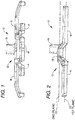
FIG. 1 is a front perspective view of one example according to an aspect of the disclosure; -
FIG. 2 is a left perspective view of the example shown inFIG. 1 ; -
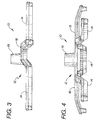
FIG. 3 is a right perspective view of the example shown inFIG. 1 ; -
FIG. 4 is a rear perspective view of the example shown inFIG. 1 ; -
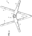
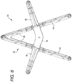
FIG. 5 is a top perspective view of the example shown inFIG. 1 ; -
FIG. 6 is a bottom perspective view of the example shown inFIG. 1 ; -
FIG. 7 is a perspective view of several examples according to an aspect of the disclosure shown inFIG. 1 as stored; -
FIG. 8 is a perspective view of an alternative example according to an aspect of the disclosure; -
FIG. 9 is a perspective view of another alternative example according to an aspect of the disclosure; -
FIG. 10 is a perspective view of another alternative example according to an aspect of the disclosure; -
FIG. 11 is a perspective view of another alternative example according to an aspect of the disclosure; -
FIGS. 12-14 are perspective views of various examples according to an aspect of the disclosure show with the pole member attached thereto; -
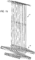
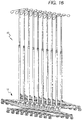
FIGS. 15-18 are perspective views of various examples of the portable intravenous stands according to an aspect of the disclosure and attaching pole members as stored; -
FIG. 19A-19C depict an embodiment of the base member of the portable intravenous stand according to the invention, whereinFIG. 19A is an elevated view thereof,FIG. 19B is a plan view thereof, andFIG. 19C shows multiple stands in storage; -
FIG. 20A-20C depict an alternate embodiment of the base member of the portable intravenous stand according to the invention, whereinFIG. 20A is a plan view thereof,FIG. 20B is an elevated view thereof, andFIG. 20C shows multiple stands in storage; -
FIG. 21 is an example of the base member of the portable intravenous stand according to an aspect of the disclosure; -
FIG. 22 is an example of the base member of the portable intravenous stand according to an aspect of the disclosure; -
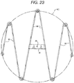
FIG. 23 is an example of the base member of the portable intravenous stand according to an aspect of the disclosure; -
FIG. 24 is an example of the base member of the portable intravenous stand according to an aspect of the disclosure; and, -
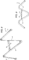
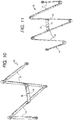
FIG. 25 is an example of the base member of the portable intravenous stand according to an aspect of the disclosure. - One example according an aspect of the disclosure is shown in
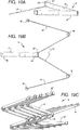
FIGS. 1-7 , wherein various views depict a portableintravenous stand 10 having abase member 12 further including a plurality ofsegments 14. The plurality ofsegments 14 lies substantially within a plane 22 (which is substantially parallel with the paper with respect toFIGS. 5 and6 ). A plurality of rotating members 16 (not shown inFIGS. 1-7 ) can be operatively connected to thebase member 12, preferably proximate the end(s) of each segment. It is to be understood that the operative connection of any part/component of the portableintravenous stand 10 contemplates utilizing any connecting mechanism known to one of ordinary skill in the art for connecting such cooperating components, such as, and not limited to: welds, bolts, screws, hinges, pivots, snaps, fittings, crimps, and alike. Anoutrigger member 18 is connected between twoadjacent segments 14 of thebase member 12, and preferably extends past the adjacent segments to provide additional stability to thestand 10. Similar to thesegments 18, a rotatingmember 16 can be attached proximate each end of theoutrigger member 18. Theoutrigger member 18 is configured such that its end, when attached to rotatingmembers 16 would lie on the circle and equidistant apart from the other rotating members. Theoutrigger member 18 includes at least a portion thereof-and preferably a substantial portion thereof-that does not lie within the same plane as the plurality ofsegments 14; that is, at least a portion of theoutrigger member 18 lies in anotherplane 23 that is above or higher than thefirst plane 22 and which is preferably substantially parallel to the first plane. The higher portion of theoutrigger member 18 facilitates the positioning of another similarly designed portableintravenous stand 10 there under and proximate thereto. SeeFIG. 7 . Asupport 19 is preferably integral to thebase member 12 and is capable of maintaining apole member 20 substantially perpendicular to theplanes segments 14 and theoutrigger member 18. - As shown in all the figures, the present invention and the aspects of the disclosure contemplate utilizing various amounts and varieties of
segments 14,outrigger members 18, and rotatingmembers 16. That is, thebase member 12 can include two ormore segments 14 of flat or rounded stock made of metal, non-metal, plastic, polymer, rubber, composite, solid, non-solid, and combinations thereof. SeeFIGS. 8-14 . The example according an aspect of the disclosure shown inFIGS. 1-7 is cast out of aluminum and powder-coated. The rotatingmembers 16 can also be selected from among a variety of types know to those of ordinary skill in that art; including and not limited to wheels, casters, balls, and rollers. - In preferred embodiments of the present invention shown in
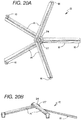
FIGS. 19A-19C and 20A-20C, abase member 12 comprises anoutrigger member 18, at least twoadjacent segments 14, and anelevated junction 27 proximate the center ofmass 24. Theoutrigger member 18, having a first end and a second end, extends from thebase member 12 proximate its center ofmass 24, but does not connect between, nor extend past,adjacent segments 14. Theoutrigger member 18 first end is connected to adjacent segments proximate thejunction 27. At least a portion of theoutrigger member 18 is elevated and perhaps inclined toward theelevated junction 27. The angle of incline can be approximately 15° but other incline angles would be acceptable. The incline is of adequate steepness to facilitate the passage of one outrigger member of onebase member 12 under another base member of an adjacent similarly configured portableintravenous stand 10 such that the poles of the stands are in close proximity. A rotating member can be attached proximate theoutrigger member 18 second end. - At least two
adjacent segments 14, having first and second ends, extend fromproximate junction 27. The first ends ofadjacent segments 14 are attached to theoutrigger member 18 first endproximate junction 27. At least a portion of theadjacent segments 14 is elevated and perhaps inclined toward theelevated junction 27. The angle of inclination can be similar to the incline ofoutrigger member 18. Rotating members can be attached proximate the adjacent segment second ends. - The
junction 27 is elevated above theoutrigger member 18 andadjacent segments 14 second ends such that the center of mass is in a first plane and the second ends are in a second plane parallel to the first plane. Theelevated junction 27 facilitates the passage ofoutrigger member 18 of another similarly configured portableintravenous stand 10 under thejunction 27 and positioning of thestands 10 in close proximity. SeeFIGS. 19C and20C . Asupport 19 is attachedproximate junction 27. A rotating member, not shown, can be attached proximate each second end ofoutrigger member 18 andsegments 14. Additional segments 14' can be attached proximate second ends ofsegments 14 to improve the stability of the base. - In all examples of aspects of the present disclosure including the
outrigger member 18 extending between at least twosegments 14 of the base member 12-e.g.,FIGS. 1-18 ,23 , and24 -it is preferable that at least a portion of the outrigger member is raised above a portion of the plurality of segments such that during storage, a portion of the segment of anadjacent stand 10 is capable of passing under the outrigger member to facilitate close positioning of the stands as shown inFIGS. 7 and15-18 . While theoutrigger member 18 has been shown extending between twoadjacent segments 14 closest to the center of thebase member 12, it is to be understood that the outrigger member can extend past the segments (as shown inFIGS. 1-7 ) and/or be attached to other segments as well. Additionaldiscrete outrigger members 18 can also be utilized to branch between subsequentadjacent segments 14 to provide increased sturdiness to thebase member 10. Theadditional outrigger members 18 preferably also include at least a portion raised above a portion of the plurality ofsegments 14, which facilitates close positioning of additional stands during storage. Theadditional outrigger member 18 can be branched between at least any two segments 14-not necessarily immediately adjacent segments-and is not required to be aligned such that if extended further, it would eventually pass proximate to the base member's center. The present example of an aspect of the disclosure further contemplates that anadditional support 19 can be attached or integral with the additionaldiscrete outrigger member 18. - In yet another examples according to an aspect of the disclosure shown in
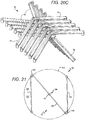
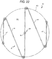
FIGS. 21 and22 , the portableintravenous stand 10 includes abase member 12 having a center ofmass 24 and lying substantially within a plane 22 (substantially parallel with the paper). Thebase member 12 includes amain segment 26 that preferably extends through or proximate the base member's 12 center ofmass 24. A firstadjacent segment 28 having a first and second end is attached to afirst end 30 of the main segment, and a secondadjacent segment 32 having a first and second end is attached to asecond end 34 of themain segment 26 forming a Z-shapedbase 12. An angle α between themain segment 26 and firstadjacent segment 28 and secondadjacent segment 32 is formed at the points of attachment. The angle α can be approximately 15° to 75°. A first rotating member (not shown inFIGS. 21 and22 ) can be attached proximate the attachment of themain segment 26 and the firstadjacent segment 28, and a second rotating member (not shown inFIGS. 21 and22 ) can be attached proximate the attachment location of themain segment 26 and the secondadjacent segment 32. Additional segments 14' can be attached proximate the second end ofadjacent segments 14 forming abase member 12 having a zig-zag form. The additional segments 14' increase the stability of the stand. Rotating members can be attached to the free ends of the segments 14'. A pole member 20 (not shown inFIGS. 21 and22 ) can extend substantially vertical from thesupport 19 that is preferably integral with thebase member 12 and proximate the center ofmass 24, such that the base member enables the close positioning of corresponding segments of other similarly designed portable intravenous stands. An additional rotatingmember 16 can be attached to themain segment 26 of thebase member 12 and proximate its center ofmass 24 and/orsupport 19. - As shown in
FIGS. 21 - 23 -and which is also applicable to the embodiments of the present invention shown inFIGS. 19A - 20C -a pair of rotating members can be attached to thebase member 12, wherein the pair of rotating members lie upon a circumference of acircle 40 that lies parallel to theplane 22 wherein the circle's center is preferably aligned with the center of thesupport 19, which is preferably proximate to the stand's 10 center ofmass 24. Additional rotating members can further be attached to thebase member 12 and also located about thecircumference 40 and preferably an equal distance apart from each other along the path of the circumference. - Referring back to
FIGS. 1-7 , theoutrigger member 18 is configured such that the rotating members attached to its ends, which extend past theadjacent segments 14, lie on thecircumference 40 along with the other rotating members, wherein the rotating members are preferable positioned an equal distance apart from each other along the path of the circumference. InFIGS. 1-7 , one half of the outrigger member is substantially perpendicular to one of the adjacent segments and the other half of the outrigger member is substantially perpendicular to the other of the adjacent segments. The equidistant spacing of rotatingmembers 16 about thecircumference 40 provides substantial stability to the base member. - It is to be noted however that not all rotating
members 16 need to be located proximate thecircumference 40, but rather can be spaced a different distance from thesupport 19. In other words, other rotating members, preferably in pairs, can be positioned about another circle having a different circumference that is concentric with thefirst circumference 40 about thesupport 19, or the center ofmass 24 of thestand 10; but where the concentric circumferences have different diameters (seeFIGS. 24 and 25 ). - It is to be understood that additional embodiments of the present invention described herein may be contemplated by one of ordinary skill in the art and the scope of the present invention is not limited to the embodiments disclosed. While specific embodiments of the present invention have been illustrated and described, numerous modifications come to mind and the scope of protection is only limited by the scope of the accompanying claims.
Claims (2)
- A portable intravenous stand comprising:a base member (12) including a plurality of segments (14), wherein the plurality of segments (14) further includea first segment (14) having a first end and a second end;a second segment (14) having a first end and a second end wherein the first end of the second segment (14) is operatively connected to the first end of the first segment (14) forming a first junction (27) lying within a first plane;an outrigger member (18) having a first end and a second end wherein the outrigger member (18) first end is operatively attached to the first junction (27) such that the first junction (27) is elevated above the outrigger member (18);a first rotating member (16) operatively attached proximate the second end of the first segment (14);a second rotating member (16) operatively attached proximate the second end of the second segment (14);a third rotating member (16) operatively attached proximate the second end of the outrigger member (18) wherein the first, second and third rotating members (16) are within a second plane parallel to and lower than the first plane,whereby the portable intravenous stand (10) comprisesa circle lying within the second plane, wherein the first, second and third rotating members (16) essentially lie upon a circumference of the circle, anda support (19) integral to the base member (12) and capable of maintaining a pole member (20) substantially perpendicular to the first plane,wherein the elevated junction (27) facilitates the passage of the outrigger member (18) of another similarly configured portable intravenous stand (10) under the junction (27) and positioning of the stands (10) in close proximity.
- The portable intravenous stand of claim 1 wherein the segments (14) and outrigger member (18) incline from the second plane to the first plane to further facilitate the positioning of a similarly configured portable intravenous stand (10) there under and proximate thereto.
Applications Claiming Priority (3)
| Application Number | Priority Date | Filing Date | Title |
|---|---|---|---|
| US12/287,535 US8196874B2 (en) | 2007-10-12 | 2008-10-10 | Storable intravenous stands |
| PCT/US2008/013264 WO2010042091A1 (en) | 2008-10-10 | 2008-12-02 | Storable intravenous stands |
| EP08877328.8A EP2334216B1 (en) | 2008-10-10 | 2008-12-02 | Storable intravenous stands |
Related Parent Applications (1)
| Application Number | Title | Priority Date | Filing Date |
|---|---|---|---|
| EP08877328.8A Division EP2334216B1 (en) | 2008-10-10 | 2008-12-02 | Storable intravenous stands |
Publications (2)
| Publication Number | Publication Date |
|---|---|
| EP3381332A1 EP3381332A1 (en) | 2018-10-03 |
| EP3381332B1 true EP3381332B1 (en) | 2021-04-14 |
Family
ID=40720619
Family Applications (4)
| Application Number | Title | Priority Date | Filing Date |
|---|---|---|---|
| EP18167460.7A Active EP3381331B1 (en) | 2008-10-10 | 2008-12-02 | Storable intravenous stands |
| EP08877328.8A Active EP2334216B1 (en) | 2008-10-10 | 2008-12-02 | Storable intravenous stands |
| EP18167461.5A Active EP3381332B1 (en) | 2008-10-10 | 2008-12-02 | Storable intravenous stands |
| EP21161043.1A Withdrawn EP3851138A1 (en) | 2008-10-10 | 2008-12-02 | Storable intravenous stands |
Family Applications Before (2)
| Application Number | Title | Priority Date | Filing Date |
|---|---|---|---|
| EP18167460.7A Active EP3381331B1 (en) | 2008-10-10 | 2008-12-02 | Storable intravenous stands |
| EP08877328.8A Active EP2334216B1 (en) | 2008-10-10 | 2008-12-02 | Storable intravenous stands |
Family Applications After (1)
| Application Number | Title | Priority Date | Filing Date |
|---|---|---|---|
| EP21161043.1A Withdrawn EP3851138A1 (en) | 2008-10-10 | 2008-12-02 | Storable intravenous stands |
Country Status (6)
| Country | Link |
|---|---|
| US (4) | US8196874B2 (en) |
| EP (4) | EP3381331B1 (en) |
| JP (2) | JP5214740B2 (en) |
| AU (1) | AU2008362797A1 (en) |
| CA (1) | CA2702108C (en) |
| WO (1) | WO2010042091A1 (en) |
Families Citing this family (24)
| Publication number | Priority date | Publication date | Assignee | Title |
|---|---|---|---|---|
| US8196874B2 (en) * | 2007-10-12 | 2012-06-12 | Maxtec, Llc | Storable intravenous stands |
| JP4583435B2 (en) * | 2007-12-19 | 2010-11-17 | 株式会社三菱東京Ufj銀行 | stand |
| JP4907704B2 (en) * | 2009-09-03 | 2012-04-04 | 株式会社三菱東京Ufj銀行 | stand |
| GB2481649A (en) * | 2010-07-03 | 2012-01-04 | Paul Francis Brady | Stackable base for IV stand |
| CA2719687A1 (en) | 2010-11-01 | 2012-05-01 | 2240978 Ontario Inc. | Carrier for patient fluids |
| US8733719B2 (en) * | 2010-11-12 | 2014-05-27 | Wildcard Enterprises Llc | Method and apparatus for use in management of medical intravenous pole assemblies |
| JP5857387B2 (en) * | 2011-09-09 | 2016-02-10 | コクヨ株式会社 | Drip stand |
| US11813425B2 (en) * | 2011-12-29 | 2023-11-14 | Medline Industries, Lp | Apparatus pertaining to a base for a vertical support pole |
| US9737654B2 (en) | 2011-12-29 | 2017-08-22 | Medline Industries, Inc. | Intravenous pole base having tessellating elements |
| JP5989472B2 (en) * | 2012-09-14 | 2016-09-07 | アトムメディカル株式会社 | Gartle stand |
| US9079597B2 (en) | 2013-02-06 | 2015-07-14 | Spg International Llc | Adjustable rack |
| US9661858B2 (en) * | 2014-04-08 | 2017-05-30 | National Cart Co., Inc. | Nesting baking oven racks |
| WO2016077729A1 (en) * | 2014-11-13 | 2016-05-19 | The Research Institute At Nationwide Children's Hospital | Nesting intravenous stand and walking support |
| US10582981B2 (en) | 2016-02-02 | 2020-03-10 | Stryker Corporation | Accessory support and coupling systems for an accessory support |
| US10426887B2 (en) * | 2016-06-21 | 2019-10-01 | Pedigo Products, Inc. | Handle for mobile stand for use with intravenous delivery of medications |
| USD820978S1 (en) | 2017-03-31 | 2018-06-19 | Pedigo Products, Inc. | Wheeled base |
| USD870799S1 (en) * | 2017-06-06 | 2019-12-24 | Arlo Technologies, Inc. | Flexible camera mount |
| US11007102B2 (en) | 2017-08-22 | 2021-05-18 | Stryker Corporation | Patient transport system |
| US11344115B2 (en) * | 2019-11-21 | 2022-05-31 | Harvest Supply Canada Inc. | System of racks for space saving storage |
| USD911870S1 (en) * | 2020-05-27 | 2021-03-02 | Centresky Crafts(Shantou)Co., Ltd | Tree stand |
| CN114949433B (en) * | 2021-02-24 | 2024-04-09 | 贝泰企业有限公司 | Insertion and storage type medical drip moving seat |
| WO2022183291A1 (en) * | 2021-03-04 | 2022-09-09 | Mark Sunderland | Pole support systems and methods |
| US11766517B2 (en) * | 2021-03-17 | 2023-09-26 | Better Enterprise Co., Ltd. | Insert-storage type intravenous drip moving seat |
| JP7120675B1 (en) * | 2021-03-24 | 2022-08-17 | 貝泰企業有限公司 | Penetration Retractable Medical Infusion Mobile Base |
Family Cites Families (58)
| Publication number | Priority date | Publication date | Assignee | Title |
|---|---|---|---|---|
| US1893799A (en) * | 1930-11-21 | 1933-01-10 | Central Scientific Co | Laboratory support |
| US2170006A (en) * | 1937-09-27 | 1939-08-22 | Robert J Brandt | Base construction |
| US3026079A (en) * | 1960-04-04 | 1962-03-20 | Mary E Stack | Adjustable support means for liquid dispensing vessels |
| US3272528A (en) | 1964-08-03 | 1966-09-13 | Unarco Industries | Nestable cart |
| US3303938A (en) * | 1966-01-17 | 1967-02-14 | Solomon Archie | Garment rack |
| DE6750494U (en) * | 1968-07-13 | 1969-01-09 | Koenig & Meyer | INFUSION STAND |
| US3889910A (en) * | 1973-03-08 | 1975-06-17 | Ratus W Walters | Floor stand support and bracing system |
| US3888442A (en) * | 1973-09-07 | 1975-06-10 | Harold J Comeaux | Garbage bag support and storage device |
| US4054209A (en) * | 1976-04-07 | 1977-10-18 | Harold Solomon Trust | Garment rack |
| US4332378A (en) * | 1980-04-15 | 1982-06-01 | Pryor John W | Ambulatory patient support stand |
| US4456273A (en) * | 1980-09-12 | 1984-06-26 | Mckinnon Crerand | Load-carrying trolleys |
| US4541596A (en) | 1982-09-13 | 1985-09-17 | Price Ronald K | Portable intravenous pole for use in an emergency |
| US4541598A (en) * | 1983-08-05 | 1985-09-17 | The Cooperative Marketing Co. | Hanger for mounting items |
| US4744536A (en) * | 1986-06-25 | 1988-05-17 | Icu Medical, Inc. | Collapsable pole and stand combination |
| JPH0715025Y2 (en) * | 1987-01-14 | 1995-04-10 | 株式会社和田楽器 | Music stand, musical instrument stand |
| USD310570S (en) * | 1988-02-08 | 1990-09-11 | Wells James A | Portable intravenous pole |
| US4911308A (en) * | 1988-11-07 | 1990-03-27 | Saxvikens Mat Ab | Mobile plate stand |
| US4905944A (en) * | 1989-01-26 | 1990-03-06 | Baxter International Inc. | Home care intravenous stand |
| DE4020434A1 (en) * | 1989-07-01 | 1991-01-17 | Geyer Hans Juergen Dipl Design | Stand for blood transfusion appts. - has cross-bars which can be adjusted for height |
| US5048789A (en) * | 1990-01-02 | 1991-09-17 | Ultimate Support Systems, Inc. | Microphone stand |
| US5125520A (en) * | 1991-07-23 | 1992-06-30 | Junzaburo Kawasaki | Tray rack |
| US5344169A (en) | 1992-01-27 | 1994-09-06 | Pryor Products | Multi-pole support stand |
| US5458305A (en) * | 1993-05-17 | 1995-10-17 | Woodward; John | Portable intravenous support stand |
| JPH0715025A (en) | 1993-06-21 | 1995-01-17 | Sanyo Electric Co Ltd | Manufacture of photovoltaic device |
| US5479953A (en) * | 1993-12-20 | 1996-01-02 | Pasulka; Patrick S. | Portable intravenous equipment console and walker apparatus for an ambulatory patient |
| US5556065A (en) * | 1994-10-19 | 1996-09-17 | Wadley; Robert D. | Intensive care equipment carriage |
| US5501419A (en) * | 1994-12-08 | 1996-03-26 | Huang; Ching-Feng | Chair leg assembly with three legs |
| US5680429A (en) | 1995-01-18 | 1997-10-21 | Shimadzu Corporation | X-ray generating apparatus and X-ray microscope |
| US5957309A (en) * | 1995-02-10 | 1999-09-28 | Hall; Donald M. | Tray rack |
| AUPN265895A0 (en) * | 1995-04-28 | 1995-05-25 | Risk Management Resources Pty Ltd | Control wheel assembly for trolleys |
| NL1002714C2 (en) * | 1996-03-26 | 1997-09-30 | Revab Bv | Nestable wheelchair and wheelchair assembly for use in such an assembly. |
| JP3182513B2 (en) * | 1998-03-12 | 2001-07-03 | 株式会社イトーキ | Panel furniture |
| US6203035B1 (en) * | 1998-04-29 | 2001-03-20 | V. John Ondrasik | Nestable platter cart |
| CA2287783C (en) * | 1998-11-05 | 2005-09-20 | Kabushiki Kaisha Kobe Seiko Sho | Method for the compaction of powders for powder metallurgy |
| USD457239S1 (en) * | 1999-04-23 | 2002-05-14 | Burton J. Kunik | Pole apparatus for hanging intravenous bags or other similar devices |
| US6158701A (en) * | 1999-09-03 | 2000-12-12 | Deshler; Donald T. | Painting stand for vehicle parts |
| JP2001129057A (en) * | 1999-11-05 | 2001-05-15 | Senko Medical Instr Mfg Co Ltd | Stand for drip infusion |
| DE19963382A1 (en) * | 1999-12-28 | 2001-07-12 | Bosch Gmbh Robert | Micromirror |
| US20020096608A1 (en) | 2001-01-19 | 2002-07-25 | Cedarberg Industries, Inc. | IV stand cord/tube holder |
| US6382434B1 (en) | 2001-04-04 | 2002-05-07 | Keith E. Silberg | Compact foldable merchandising display rack |
| MXPA04002231A (en) | 2001-09-12 | 2005-03-07 | Acordis Speciality Fibres Ltd | Antibacterial wound dressing. |
| JP3755754B2 (en) * | 2001-10-31 | 2006-03-15 | パラマウントベッド株式会社 | Grasping and moving operation device for Illrigator stand |
| CA2381886A1 (en) | 2002-04-17 | 2003-10-17 | Patrick Murray | Nesting rack |
| JP3466180B2 (en) * | 2002-04-22 | 2003-11-10 | 国一 宮地 | Multifunctional drip stand |
| US6749208B2 (en) * | 2002-05-03 | 2004-06-15 | Precision Wire Racks And Carts, Inc. | Nestable platter cart |
| JP2004049491A (en) * | 2002-07-18 | 2004-02-19 | Toho Press Kogyo Kk | Infusion stand |
| DE20219431U1 (en) * | 2002-12-16 | 2003-03-27 | Leidig Christoph | Foot structure in the form of a circularly bent pipe element for an infusion stand comprises a gap, and is provided with an eccentrically positioned column |
| EP1605887A2 (en) | 2003-03-18 | 2005-12-21 | Hill-Rom Services, Inc. | Patient care equipment management system |
| US20060196997A1 (en) | 2005-03-04 | 2006-09-07 | Johnson Sheila E | Movable and adjustable cooler stand |
| US7216875B2 (en) | 2005-09-16 | 2007-05-15 | Unarco Industries, Inc. | Shopping cart having caster lift |
| WO2007056830A1 (en) * | 2005-11-21 | 2007-05-24 | About Time Technologies Pty Ltd | Mobility frame |
| EP1790249B1 (en) | 2005-11-25 | 2011-08-31 | Ondal Holding GmbH | Stand with a securing device |
| NL1030782C2 (en) * | 2005-12-27 | 2007-06-28 | Endomed B V | Mobile infusion post comprises horizontally extending frame with first half provided with downwardly extending wheels and rear half with rear downwardly extending wheels |
| WO2008085698A2 (en) | 2007-01-03 | 2008-07-17 | Firefly Medical, Inc. | Integrated infusion management system |
| US8196874B2 (en) * | 2007-10-12 | 2012-06-12 | Maxtec, Llc | Storable intravenous stands |
| US7631773B1 (en) * | 2007-12-13 | 2009-12-15 | Calabrisotto Dianne | Personal rolling valet |
| US8313066B2 (en) * | 2008-06-25 | 2012-11-20 | Medline Industries, Inc. | Intravenous fluid container stand and methods for making same |
| GB2481649A (en) * | 2010-07-03 | 2012-01-04 | Paul Francis Brady | Stackable base for IV stand |
-
2008
- 2008-10-10 US US12/287,535 patent/US8196874B2/en active Active
- 2008-12-02 AU AU2008362797A patent/AU2008362797A1/en not_active Abandoned
- 2008-12-02 EP EP18167460.7A patent/EP3381331B1/en active Active
- 2008-12-02 CA CA2702108A patent/CA2702108C/en active Active
- 2008-12-02 EP EP08877328.8A patent/EP2334216B1/en active Active
- 2008-12-02 JP JP2010537929A patent/JP5214740B2/en active Active
- 2008-12-02 WO PCT/US2008/013264 patent/WO2010042091A1/en active Application Filing
- 2008-12-02 EP EP18167461.5A patent/EP3381332B1/en active Active
- 2008-12-02 EP EP21161043.1A patent/EP3851138A1/en not_active Withdrawn
-
2012
- 2012-05-11 US US13/469,863 patent/US8657241B2/en active Active
-
2013
- 2013-02-26 JP JP2013036222A patent/JP5607195B2/en active Active
-
2014
- 2014-02-24 US US14/187,943 patent/US9227007B2/en active Active
-
2015
- 2015-12-28 US US14/979,762 patent/US10046107B2/en active Active
Non-Patent Citations (1)
| Title |
|---|
| None * |
Also Published As
| Publication number | Publication date |
|---|---|
| US10046107B2 (en) | 2018-08-14 |
| AU2008362797A1 (en) | 2010-04-15 |
| CA2702108C (en) | 2015-11-24 |
| US20090146027A1 (en) | 2009-06-11 |
| CA2702108A1 (en) | 2010-04-15 |
| US20120217711A1 (en) | 2012-08-30 |
| EP2334216A4 (en) | 2015-05-27 |
| US20140166828A1 (en) | 2014-06-19 |
| EP3851138A1 (en) | 2021-07-21 |
| JP2013135882A (en) | 2013-07-11 |
| EP2334216B1 (en) | 2018-04-18 |
| US9227007B2 (en) | 2016-01-05 |
| WO2010042091A1 (en) | 2010-04-15 |
| US20160184508A1 (en) | 2016-06-30 |
| US8196874B2 (en) | 2012-06-12 |
| JP2011505962A (en) | 2011-03-03 |
| JP5607195B2 (en) | 2014-10-15 |
| EP3381331B1 (en) | 2021-04-07 |
| JP5214740B2 (en) | 2013-06-19 |
| US8657241B2 (en) | 2014-02-25 |
| EP2334216A1 (en) | 2011-06-22 |
| EP3381331A1 (en) | 2018-10-03 |
| EP3381332A1 (en) | 2018-10-03 |
Similar Documents
| Publication | Publication Date | Title |
|---|---|---|
| EP3381332B1 (en) | Storable intravenous stands | |
| US7494019B2 (en) | Modular cantilevered shelving assembly and method | |
| EP0993263B1 (en) | Pivotal display rack | |
| EP1035791A1 (en) | Self standing merchandiser | |
| US20110278246A1 (en) | Display having variable incline shelves | |
| US20030213415A1 (en) | Computer desk | |
| US8342343B2 (en) | Free-standing, point-of-purchase display | |
| US20160374466A1 (en) | Gondola gravity feed conversion bracket system | |
| US6991306B2 (en) | Carrousel file | |
| US8141724B2 (en) | Double sided bin holder assembly | |
| US6315136B1 (en) | Storage bin shelving system | |
| CA2287826A1 (en) | Product shelving construction | |
| CN210902379U (en) | Shelf with angle-adjustable shelf board | |
| US20070256613A1 (en) | Connector for shelving | |
| US20110266239A1 (en) | Display with multiple nesting components | |
| US11647830B1 (en) | Free standing collapsible furniture item | |
| WO2004002271A1 (en) | Carrousel file |
Legal Events
| Date | Code | Title | Description |
|---|---|---|---|
| PUAI | Public reference made under article 153(3) epc to a published international application that has entered the european phase |
Free format text: ORIGINAL CODE: 0009012 |
|
| STAA | Information on the status of an ep patent application or granted ep patent |
Free format text: STATUS: REQUEST FOR EXAMINATION WAS MADE |
|
| 17P | Request for examination filed |
Effective date: 20180416 |
|
| AC | Divisional application: reference to earlier application |
Ref document number: 2334216 Country of ref document: EP Kind code of ref document: P |
|
| AK | Designated contracting states |
Kind code of ref document: A1 Designated state(s): AT BE BG CH CY CZ DE DK EE ES FI FR GB GR HR HU IE IS IT LI LT LU LV MC MT NL NO PL PT RO SE SI SK TR |
|
| GRAP | Despatch of communication of intention to grant a patent |
Free format text: ORIGINAL CODE: EPIDOSNIGR1 |
|
| STAA | Information on the status of an ep patent application or granted ep patent |
Free format text: STATUS: GRANT OF PATENT IS INTENDED |
|
| INTG | Intention to grant announced |
Effective date: 20201110 |
|
| GRAS | Grant fee paid |
Free format text: ORIGINAL CODE: EPIDOSNIGR3 |
|
| GRAA | (expected) grant |
Free format text: ORIGINAL CODE: 0009210 |
|
| STAA | Information on the status of an ep patent application or granted ep patent |
Free format text: STATUS: THE PATENT HAS BEEN GRANTED |
|
| AC | Divisional application: reference to earlier application |
Ref document number: 2334216 Country of ref document: EP Kind code of ref document: P |
|
| AK | Designated contracting states |
Kind code of ref document: B1 Designated state(s): AT BE BG CH CY CZ DE DK EE ES FI FR GB GR HR HU IE IS IT LI LT LU LV MC MT NL NO PL PT RO SE SI SK TR |
|
| REG | Reference to a national code |
Ref country code: GB Ref legal event code: FG4D |
|
| REG | Reference to a national code |
Ref country code: CH Ref legal event code: EP |
|
| REG | Reference to a national code |
Ref country code: DE Ref legal event code: R096 Ref document number: 602008063876 Country of ref document: DE |
|
| REG | Reference to a national code |
Ref country code: IE Ref legal event code: FG4D |
|
| REG | Reference to a national code |
Ref country code: AT Ref legal event code: REF Ref document number: 1381494 Country of ref document: AT Kind code of ref document: T Effective date: 20210515 |
|
| REG | Reference to a national code |
Ref country code: SE Ref legal event code: TRGR |
|
| REG | Reference to a national code |
Ref country code: LT Ref legal event code: MG9D |
|
| REG | Reference to a national code |
Ref country code: AT Ref legal event code: MK05 Ref document number: 1381494 Country of ref document: AT Kind code of ref document: T Effective date: 20210414 |
|
| REG | Reference to a national code |
Ref country code: NL Ref legal event code: MP Effective date: 20210414 |
|
| PG25 | Lapsed in a contracting state [announced via postgrant information from national office to epo] |
Ref country code: NL Free format text: LAPSE BECAUSE OF FAILURE TO SUBMIT A TRANSLATION OF THE DESCRIPTION OR TO PAY THE FEE WITHIN THE PRESCRIBED TIME-LIMIT Effective date: 20210414 Ref country code: BG Free format text: LAPSE BECAUSE OF FAILURE TO SUBMIT A TRANSLATION OF THE DESCRIPTION OR TO PAY THE FEE WITHIN THE PRESCRIBED TIME-LIMIT Effective date: 20210714 Ref country code: AT Free format text: LAPSE BECAUSE OF FAILURE TO SUBMIT A TRANSLATION OF THE DESCRIPTION OR TO PAY THE FEE WITHIN THE PRESCRIBED TIME-LIMIT Effective date: 20210414 Ref country code: FI Free format text: LAPSE BECAUSE OF FAILURE TO SUBMIT A TRANSLATION OF THE DESCRIPTION OR TO PAY THE FEE WITHIN THE PRESCRIBED TIME-LIMIT Effective date: 20210414 Ref country code: HR Free format text: LAPSE BECAUSE OF FAILURE TO SUBMIT A TRANSLATION OF THE DESCRIPTION OR TO PAY THE FEE WITHIN THE PRESCRIBED TIME-LIMIT Effective date: 20210414 Ref country code: LT Free format text: LAPSE BECAUSE OF FAILURE TO SUBMIT A TRANSLATION OF THE DESCRIPTION OR TO PAY THE FEE WITHIN THE PRESCRIBED TIME-LIMIT Effective date: 20210414 |
|
| PG25 | Lapsed in a contracting state [announced via postgrant information from national office to epo] |
Ref country code: PT Free format text: LAPSE BECAUSE OF FAILURE TO SUBMIT A TRANSLATION OF THE DESCRIPTION OR TO PAY THE FEE WITHIN THE PRESCRIBED TIME-LIMIT Effective date: 20210816 Ref country code: NO Free format text: LAPSE BECAUSE OF FAILURE TO SUBMIT A TRANSLATION OF THE DESCRIPTION OR TO PAY THE FEE WITHIN THE PRESCRIBED TIME-LIMIT Effective date: 20210714 Ref country code: PL Free format text: LAPSE BECAUSE OF FAILURE TO SUBMIT A TRANSLATION OF THE DESCRIPTION OR TO PAY THE FEE WITHIN THE PRESCRIBED TIME-LIMIT Effective date: 20210414 Ref country code: LV Free format text: LAPSE BECAUSE OF FAILURE TO SUBMIT A TRANSLATION OF THE DESCRIPTION OR TO PAY THE FEE WITHIN THE PRESCRIBED TIME-LIMIT Effective date: 20210414 Ref country code: GR Free format text: LAPSE BECAUSE OF FAILURE TO SUBMIT A TRANSLATION OF THE DESCRIPTION OR TO PAY THE FEE WITHIN THE PRESCRIBED TIME-LIMIT Effective date: 20210715 Ref country code: IS Free format text: LAPSE BECAUSE OF FAILURE TO SUBMIT A TRANSLATION OF THE DESCRIPTION OR TO PAY THE FEE WITHIN THE PRESCRIBED TIME-LIMIT Effective date: 20210814 |
|
| REG | Reference to a national code |
Ref country code: DE Ref legal event code: R097 Ref document number: 602008063876 Country of ref document: DE |
|
| PG25 | Lapsed in a contracting state [announced via postgrant information from national office to epo] |
Ref country code: SK Free format text: LAPSE BECAUSE OF FAILURE TO SUBMIT A TRANSLATION OF THE DESCRIPTION OR TO PAY THE FEE WITHIN THE PRESCRIBED TIME-LIMIT Effective date: 20210414 Ref country code: EE Free format text: LAPSE BECAUSE OF FAILURE TO SUBMIT A TRANSLATION OF THE DESCRIPTION OR TO PAY THE FEE WITHIN THE PRESCRIBED TIME-LIMIT Effective date: 20210414 Ref country code: ES Free format text: LAPSE BECAUSE OF FAILURE TO SUBMIT A TRANSLATION OF THE DESCRIPTION OR TO PAY THE FEE WITHIN THE PRESCRIBED TIME-LIMIT Effective date: 20210414 Ref country code: RO Free format text: LAPSE BECAUSE OF FAILURE TO SUBMIT A TRANSLATION OF THE DESCRIPTION OR TO PAY THE FEE WITHIN THE PRESCRIBED TIME-LIMIT Effective date: 20210414 Ref country code: CZ Free format text: LAPSE BECAUSE OF FAILURE TO SUBMIT A TRANSLATION OF THE DESCRIPTION OR TO PAY THE FEE WITHIN THE PRESCRIBED TIME-LIMIT Effective date: 20210414 Ref country code: DK Free format text: LAPSE BECAUSE OF FAILURE TO SUBMIT A TRANSLATION OF THE DESCRIPTION OR TO PAY THE FEE WITHIN THE PRESCRIBED TIME-LIMIT Effective date: 20210414 |
|
| PLBE | No opposition filed within time limit |
Free format text: ORIGINAL CODE: 0009261 |
|
| STAA | Information on the status of an ep patent application or granted ep patent |
Free format text: STATUS: NO OPPOSITION FILED WITHIN TIME LIMIT |
|
| 26N | No opposition filed |
Effective date: 20220117 |
|
| PG25 | Lapsed in a contracting state [announced via postgrant information from national office to epo] |
Ref country code: IS Free format text: LAPSE BECAUSE OF FAILURE TO SUBMIT A TRANSLATION OF THE DESCRIPTION OR TO PAY THE FEE WITHIN THE PRESCRIBED TIME-LIMIT Effective date: 20210814 |
|
| PG25 | Lapsed in a contracting state [announced via postgrant information from national office to epo] |
Ref country code: MC Free format text: LAPSE BECAUSE OF FAILURE TO SUBMIT A TRANSLATION OF THE DESCRIPTION OR TO PAY THE FEE WITHIN THE PRESCRIBED TIME-LIMIT Effective date: 20210414 Ref country code: IT Free format text: LAPSE BECAUSE OF FAILURE TO SUBMIT A TRANSLATION OF THE DESCRIPTION OR TO PAY THE FEE WITHIN THE PRESCRIBED TIME-LIMIT Effective date: 20210414 |
|
| PG25 | Lapsed in a contracting state [announced via postgrant information from national office to epo] |
Ref country code: LU Free format text: LAPSE BECAUSE OF NON-PAYMENT OF DUE FEES Effective date: 20211202 Ref country code: IE Free format text: LAPSE BECAUSE OF NON-PAYMENT OF DUE FEES Effective date: 20211202 |
|
| PGFP | Annual fee paid to national office [announced via postgrant information from national office to epo] |
Ref country code: BE Payment date: 20220915 Year of fee payment: 15 |
|
| PGFP | Annual fee paid to national office [announced via postgrant information from national office to epo] |
Ref country code: CH Payment date: 20230101 Year of fee payment: 15 |
|
| PG25 | Lapsed in a contracting state [announced via postgrant information from national office to epo] |
Ref country code: HU Free format text: LAPSE BECAUSE OF FAILURE TO SUBMIT A TRANSLATION OF THE DESCRIPTION OR TO PAY THE FEE WITHIN THE PRESCRIBED TIME-LIMIT; INVALID AB INITIO Effective date: 20081202 Ref country code: CY Free format text: LAPSE BECAUSE OF FAILURE TO SUBMIT A TRANSLATION OF THE DESCRIPTION OR TO PAY THE FEE WITHIN THE PRESCRIBED TIME-LIMIT Effective date: 20210414 |
|
| P01 | Opt-out of the competence of the unified patent court (upc) registered |
Effective date: 20230524 |
|
| PGFP | Annual fee paid to national office [announced via postgrant information from national office to epo] |
Ref country code: GB Payment date: 20231108 Year of fee payment: 16 |
|
| PGFP | Annual fee paid to national office [announced via postgrant information from national office to epo] |
Ref country code: SE Payment date: 20231208 Year of fee payment: 16 Ref country code: FR Payment date: 20231108 Year of fee payment: 16 Ref country code: DE Payment date: 20231108 Year of fee payment: 16 |
|
| PGFP | Annual fee paid to national office [announced via postgrant information from national office to epo] |
Ref country code: BE Payment date: 20231109 Year of fee payment: 16 |