EP3381108B1 - Verfahren zur herstellung einer spulenwicklung zum einlegen in radial offene nuten von statoren oder rotoren von elektromaschinen - Google Patents
Verfahren zur herstellung einer spulenwicklung zum einlegen in radial offene nuten von statoren oder rotoren von elektromaschinen Download PDFInfo
- Publication number
- EP3381108B1 EP3381108B1 EP16800986.8A EP16800986A EP3381108B1 EP 3381108 B1 EP3381108 B1 EP 3381108B1 EP 16800986 A EP16800986 A EP 16800986A EP 3381108 B1 EP3381108 B1 EP 3381108B1
- Authority
- EP
- European Patent Office
- Prior art keywords
- wires
- holding
- winding
- wire
- holding region
- Prior art date
- Legal status (The legal status is an assumption and is not a legal conclusion. Google has not performed a legal analysis and makes no representation as to the accuracy of the status listed.)
- Active
Links
- 238000004804 winding Methods 0.000 title claims description 228
- 238000004519 manufacturing process Methods 0.000 title claims description 11
- 238000000034 method Methods 0.000 claims description 102
- 238000006073 displacement reaction Methods 0.000 claims description 15
- 238000005452 bending Methods 0.000 claims description 6
- 230000009471 action Effects 0.000 claims description 5
- 238000005491 wire drawing Methods 0.000 claims description 4
- 230000008569 process Effects 0.000 description 36
- 238000007493 shaping process Methods 0.000 description 8
- 208000012886 Vertigo Diseases 0.000 description 3
- 230000015572 biosynthetic process Effects 0.000 description 3
- 230000008859 change Effects 0.000 description 3
- 238000013461 design Methods 0.000 description 3
- 238000005096 rolling process Methods 0.000 description 3
- 230000008901 benefit Effects 0.000 description 2
- 239000004020 conductor Substances 0.000 description 2
- 238000010276 construction Methods 0.000 description 2
- 238000010924 continuous production Methods 0.000 description 2
- 238000005520 cutting process Methods 0.000 description 2
- 238000011161 development Methods 0.000 description 2
- 230000018109 developmental process Effects 0.000 description 2
- 230000000694 effects Effects 0.000 description 2
- 229910052739 hydrogen Inorganic materials 0.000 description 2
- 238000009434 installation Methods 0.000 description 2
- 239000000463 material Substances 0.000 description 2
- 230000007704 transition Effects 0.000 description 2
- 230000001960 triggered effect Effects 0.000 description 2
- 208000036829 Device dislocation Diseases 0.000 description 1
- 230000004323 axial length Effects 0.000 description 1
- 238000007630 basic procedure Methods 0.000 description 1
- 230000005540 biological transmission Effects 0.000 description 1
- 230000003111 delayed effect Effects 0.000 description 1
- 239000012530 fluid Substances 0.000 description 1
- 238000010348 incorporation Methods 0.000 description 1
- 238000003780 insertion Methods 0.000 description 1
- 230000037431 insertion Effects 0.000 description 1
- 238000000465 moulding Methods 0.000 description 1
- 230000008092 positive effect Effects 0.000 description 1
- 238000012545 processing Methods 0.000 description 1
- 230000003252 repetitive effect Effects 0.000 description 1
- 230000000087 stabilizing effect Effects 0.000 description 1
- 230000001360 synchronised effect Effects 0.000 description 1
- 238000012546 transfer Methods 0.000 description 1
Images


Classifications
-
- H—ELECTRICITY
- H02—GENERATION; CONVERSION OR DISTRIBUTION OF ELECTRIC POWER
- H02K—DYNAMO-ELECTRIC MACHINES
- H02K15/00—Methods or apparatus specially adapted for manufacturing, assembling, maintaining or repairing of dynamo-electric machines
- H02K15/04—Methods or apparatus specially adapted for manufacturing, assembling, maintaining or repairing of dynamo-electric machines of windings, prior to mounting into machines
- H02K15/0435—Wound windings
- H02K15/0478—Wave windings, undulated windings
Definitions
- the method is also particularly suitable for the use of wires which are essentially rectangular in cross section and which are preferred in view of an optimal degree of filling in the slots of the stator. Conventional winding processes for round wire cannot be used for such wire cross-sections.
- the present method mainly serves to produce a so-called distributed wave winding, which can then be inserted into the slots of a stator (or rotor).
- a distributed wave winding has a plurality of parallel wires that have straight sections that are arranged in the slots of a stator. These straight sections alternate between an inner and an adjacent outer radial position in the stator when the wire pattern moves radially around the stator.
- This distributed wave pattern contains a number X of phases or grouped grooves in the stator. In general, X is a multiple of 3, but constructions are also possible in which X is any other integer.
- the number of parallel wires in the winding pattern of the distributed wave is 2X.
- a direct winding of all wires with the number 2 X is in any case not possible with both methods, since after the displacement, which corresponds to the first bending to produce the bent winding heads by X times the distance of the wires, half of the wires are still with the wires in Area of the wire feeder would collide.
- the assembly of the two halves of the distributed wave winding is not particularly problematic, but represents an additional process step and requires exact alignment of the two halves to one another before they are inserted into a magazine, from which they are then inserted into the slots in the stator ,
- the last two steps of inserting them into the magazine and transferring them into the slots of the stator are known as such and are also used in addition to the method presented here in order to finally produce the desired stator or rotor with the windings produced.
- Subsequent feeding of the additional wires into the current process is also not possible with this process design, since wires added later would also collide with wires that were already processed with the winding step initially provided here.
- the object of the present invention is to provide a method of the type mentioned at the outset which, using a simple winding template, enables the production of the entire coil winding in one process sequence without the subsequent merging of two partial windings.
- the new process offers the advantage that all wires with a number of 2 times X (compared to two turns halves to be subsequently twisted, each with a number X of wires) can be processed in a continuous process.
- An essential aspect of the newly specified method is that before the wound wire sections are wound onto the winding template, an inclined wire section is generated in each case, which then during winding, i.e. when the winding template is rotated in steps E or I, it is bent over in the middle, thereby forming roof-shaped winding heads.
- the basic design of the method enables all the wires to be shaped together in a continuous process to form a winding, which can either take place in such a way that all the wires are fed in from the start, or the wires are successively introduced into the ongoing process.
- newly added wires are first fed in successively, then shifted in parallel with the formation of an inclined roof section and finally included in the synchronous rotation / displacement sequence.
- the process then runs at the end corresponding to the delayed number of wires at the end by the corresponding number of steps, without the process flow having to be interrupted thereby.
- One embodiment of the method provides that the wires are fed in step A using a wire pulling device, the wires being drawn off from a wire supply.
- At least two holding devices are advantageously used, a first holding device being used in step B in the first holding area and the second holding device being used in the second holding area in step C.
- the holding devices are not bound to the respective holding area but can be moved between the three holding areas, so that they can maintain the holding action not only during their displacement but also during the rotation of the winding template.
- the respective holding device moves in the third holding area in the third holding area after the holding effect has been released, in order to clamp or otherwise fix the tracked wires there.
- This procedure requires more complex mechanics and controls, and the cycle times may also be extended.
- a third holding device is therefore preferably used, which intervenes in the process sequence for the first time in step F and clamps the tracked wires in the second holding area.
- the holding action in the third holding area can then be released in close proximity to step F and the displacement of the first holding device from the third to the second holding area can be carried out as part of the next turning process of the winding template.
- the holding devices move during the turning operations of the winding template from the first to the third holding area, then during the next turning operation from the third to the second holding area and finally again from the second to the first holding area, from where the sequence of movements is repeated when the winding template is turned further ,
- the guidance of the holding device preferably also enables its individual displacement parallel to the axis of rotation of the winding template, in order to enable steps D, H and K to be carried out in the holding position.
- two holding devices coupled with respect to the rotary movement with the winding template are possible, which fix the wires alternately in the first or third holding area depending on the rotational state.
- the second holding device is then preferably decoupled from the rotational movement of the winding template and is moved between the first and second holding region, it being able to describe a curved path in order to always be arranged in the vicinity of the flat winding template when it executes its rotational movement.
- the first and third holding devices are preferably moved radially and axially with respect to the axis of rotation of the winding template between two end positions, the wires being free in a radially outer position and the wires being fixed in a radially inner position.
- the holding devices are moved in the axial direction to a maximally extended end position when the shifting step D, H or K is carried out. In the opposite axial end position, the retracted holding device can be moved past the wires when it is moved from the third to the first holding area with the winding template.
- the winding overhangs are finally formed in the region of the bending region formed in step E or I from the inclined wire region by turning the winding template.
- This shaping process can compensate for any irregularities in the shape of the winding overhangs and in particular also serves to further reduce the already discussed protrusion of the winding overhangs over the stator or rotor in the sense of the advantage according to the invention which is given in any case.
- a molding tool can be used here, which is pressed against the end windings.
- the wires are cut in step L in a preferably in a rotational position of the winding template, in which the initially fed wire ends lie on the side of the winding template on which the wire is fed. In this way, it is achieved that the connections at both ends of the coil winding lie on the same side after the winding has been inserted into the stator or rotor, which simplifies their contacting.
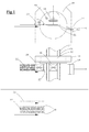
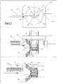
- Fig. 1 shows the starting position at the beginning of a method for producing a coil winding 70 for a stator of an electric motor (not shown).
- a winding device 10 is available in the exemplary embodiment shown, which has a winding head 12 with a wire handling device 14, which has a wire pulling device 16, three wire holding devices 18, 20, 22 (see also Figure 5 ) and a winding head forming device 24.
- the winding device 10 works together with a winding template 26 which is designed as a flat template, ie has a strip-like shape.
- the cross section of the winding template 26 is shown in the upper part a of FIG Fig.1 clearly from which the edge regions 27 of the winding template 26, which taper towards the flanks, and a radius of the flanks themselves become clear.
- the length of the winding template 26, which is not shown in full length, is determined by the length of the coil winding 70 to be produced and the exact design of the method, the length of the winding template 26 not having to correspond to the length of the coil winding 70 and then considerably, for example may be shorter than the coil winding 70 if it is already passed on successively from the template to a transmission device (not shown) in the course of the method.
- the winding device is also associated with a wire rolling device 28, which performs a roll forming of wires to be processed during the rotation processes for better contact with the winding template 26.
- the wire drawing device 16 pulls the parallel bundle of wires 32 into one Fig.2 Defined position shown, so that the wire starts 30 protrude a certain amount beyond the winding template 26.
- the wires 32 can pass the second holding device (B) which is not yet jammed unhindered.
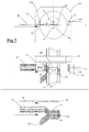
- the first holding device (A) 18 is moved from its rest position into a holding position which is approximated or in contact with the winding template 26 (see Figure 3 ).
- a first stop is defined in a first holding area 34 on the top of the flat winding template 26.
- Fig. 3 is further illustrated how the wire starts 30 are transferred by means of the wire pulling device 16 by a sideways movement of the latter into a bent wire section, which represents the connection point of the finished coil winding 70.
- a kink 38 is defined by the first holding device 18 in the first holding area 34.
- the wire drawing device is then released from the wire starts 30 and is no longer required for the rest of the execution of the method in the variant described here as an exemplary embodiment. Accordingly, the wire pulling device is moved into a rest position, which in Figure 4 is shown.
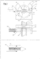
- FIG. 4 illustrates a method step in which an inclined wire section 40 is generated.
- These wire sections 40 later form winding heads 42 between straight legs 44, which lie in the slots of a stator or rotor.
- the winding heads 42 will be discussed in more detail in the subsequent method step and also later.
- the second holding device 20 is brought closer to the winding template 36 by the shifting step, because the length of the inclined section corresponds to the distance between the first holding device 34 and the second holding device 36 in Fig. 3 must correspond.
- This readjustment movement is guided and can be carried out by active tracking or by a passive compensating movement.
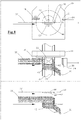
- the rotating device 28 is activated and rotates the Winding template 26 as well as the first holding device (A) 18, which is also coupled to it in the direction of rotation, from the first holding area 34 into an in Figure 5 Third holding area 46 shown, wherein the second holding device (B) 20, which is still clamped to the wires 32, is taken from the second holding area 36 into the first holding area 34 and further wire of the wires 32 is also withdrawn from the wire supply.
- the inclined wire section 40 is transferred by the rotation of the winding template into the roof-shaped winding heads 42 already mentioned because the wires nestle against the flanks of the winding template 26, the winding heads 42 tapering towards turning points 48 in accordance with the shape of the edge regions 27 and at the Turning points 48 even bending radii are formed.
- Fig. 5 the third holding device (C) 22 is also shown for the first time, but is still in a rest position here because it intervenes later in the process sequence.
- FIG. 6 An optional step is illustrated, in which the previously produced winding heads 42 are given a final shape by means of the wire forming device 24.
- the wire-forming device 24 has a shaped element 50 which is designed as a negative form of the winding heads 42 in its desired final shape and is pressed against the winding heads 42 under pressure.
- the third holding device (C) 22 is moved into the second holding area 36.
- the first holding device (A) 18 can also already be released, but can also remain jammed with the wires 32 in the third holding area 46 via the next method step.
- Fig. 7 shows, in turn provides for the formation of an inclined transition area 40 between the stop previously generated by triggering the third holding device (C) 22 in the second holding area 36 and that which is still jammed by the second holding device (B) 20, which is still in the first Holding area 34 is located. This takes place in turn by relative axial displacement of the jammed holding devices (here B and C) in the first and second holding area 34, 36 parallel to the axis of rotation of the winding template 26.
- the holding device (here A) in the third holding area 46 moves together with the holding device (here B) in the first holding area axially relative to the holding device (here C) in the second holding area 36.
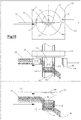
- FIG. 8c shows a complete first turn of the later coil winding on the winding template 26 with winding heads 42 on both sides of the straight legs 52, which later lie in the slots of the stator or rotor. It closes again, as in Figure 9 an optional step of shaping the winding heads 42 by means of the shaping element 50 of the wire shaping device 24, which is already in connection with FIG Fig. 6 has been explained in order to optimize the shape of the winding heads 42.
- FIG Figure 13 The final step in making the complete coil winding 70 is in FIG Figure 13 shown. At this point, a number of straight legs 52 have been generated, which are desired for the assembly of the rotor or stator slots. In Figure 13 however, only a shortened coil winding 70 is shown for better clarity. In the exemplary embodiment shown, it is desirable that all connecting wires of the finished coil winding 70 lie on one side, and the step is correspondingly carried out Figure 13 performed when the wire starts 30 are on the wire feed side.
- the finished coil winding 70 is then transferred into the stator or rotor in a manner known per se, wherein it is first stripped from the winding template and, if appropriate, inserted into a transfer device in an intermediate step.
- the method is not defined in particular with regard to the number of wires processed in parallel, which is indicated by twelve in the exemplary embodiment shown and described.
- any even number of wires can be processed in parallel.
- the method is practically suitable for any number of wires.
- the method is intended in particular for the production of coil windings 70 from flat wires which have a rectangular cross section.
- a prefabricated winding 70 is shown in the flat state, this position corresponding to the state in which the winding 70 lies on the strip-shaped template 26 which but is not shown.
- the winding 70 shown in FIG Fig. 14 only around a winding with six connecting wires each, which are formed by the wire starts 30 and the wire ends 54, that is to say X 3 in this case.
- the axial path is correspondingly reduced when the inclined transition regions 42 are shifted and formed between the straight wire sections 44.
- Fig. 15 shows as an example a stator 80, in which the winding 70 is inserted in stator slots 82.
- the connecting wires formed by the wire starts 30 and the wire ends 54 at the beginning and at the end of the winding lie on one side of the stator 80, which makes their connection easier.
- the length of the stator winding 70 is a multiple of the circumference of the stator 80, in the exemplary embodiment shown it is twice the length.
- stators produced in this way can achieve excellent degrees of filling of the grooves 82, so that the compact motors have high performance.
- the winding heads 42 flattened by the displacement ensure low material consumption and a small axial installation space of the rotor.
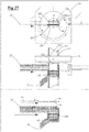
- the essential difference between the winding device 110 shown in FIG. 16 and that in FIG 1 to 13 presented winding device 10 is that not three more or less the same, for example designed as clamping devices holding devices are used, which are used in a kind of circulation in succession on all three holding areas 34, 36 and 46, but the first and third holding device 118 and 122 are coupled to the winding head 12 in the direction of rotation. Movement of the first and third retainers 118 and 122 takes place in the radial and axial direction with respect to the axis of rotation of the winding template 26.
- the second holding device 120 is designed as a wire laying device and does not rotate with the winding template 26. Nevertheless, the wire laying device, which also allows the wires 32 to be clamped in a tensile manner in their engagement area, performs an arcuate movement during the infeed movement in the direction of the winding template 26, on the one hand not to collide with the winding template and, on the other hand, to be able to place the wire as close as possible to the winding template 26, while the return movement is linear but does not have to take place. This is followed in connection with the description of 16 to 29 discussed in more detail, but the movement sequence X is also illustrated in the individual representations.
- the process state is off Fig. 1 corresponding position of all parts of the winding device 110 shown.
- the first and third holding devices 118 and 122 are in an axial rest position completely retracted into the winding head 12, in which they release the space around the winding template 26, this being not absolutely necessary in order to carry out the method steps that follow first.
- the wire laying device as the second holding device 120 is in a released rest position, ie the wire beginnings 30 passing through it are in turn not jammed with it or fixed in any other way with it.
- the simultaneous processing of all the wires is shown as an example, it also being possible for the wires to be fed successively in the course of the method.
- the wire pulling device 16 pulls the parallel bundle of wires 32 into the in FIG Fig. 17 shown position where the wire starts protrude a certain amount beyond the winding template 26, while they pass the wire laying device.
- the first holding device is then positioned axially above the wires 32 and then lowered radially toward the winding template 26, so that the wires are fixed in the region of the legs 44 to be formed (see Fig. 18 ).
- the wire pulling device then moves parallel to the axis of rotation of the winding template 26 to form the bent connection lugs of the later winding 70.
- the next step to that in FIG Fig. 19 shown state again consists in axially displacing the first holding device 118 relative to the second holding device 120 to produce the inclined wire section 40, the path being equal to half the width of the entire wire bundle, regardless of the number of wires being processed.
- Fig. 20 For a better understanding of the subsequent winding process with formation of the winding heads 42, is in Fig. 20 an intermediate step is shown, in which the winding template 26 has only been rotated by 90 °. It can be clearly seen that the first holding device 118 still fixes the wires 32 on the winding template 26, ie remains in the position axially offset by half the width.
- the wire rolling device 28 ensures that the wires nestle against the basic shape of the winding template during the rotation, while the wire laying device as the second holding device 120 remains axially in the same position and describes an arcuate path during the turning process of the winding template 28, which results if the tip of the wire laying device follows the outer contour of the rotating winding template 26.
- the third holding device 122 is located in FIG Fig. 20 and 21 illustrated rotation process in an axially retracted position and can for example be completely retracted into the winding head. As a result, it dodges the wire laying device and the wires 32 located in the vicinity of the winding template.
- the wire pulling device in deviation from the mode of operation of the in 1 to 13 shown winding device 10 here, the wire pulling device remains clamped with the wire ends 30 and follows the rotational movement of the winding template 26.
- the wire pulling device stabilizes the wires 32 and serves as additional support so that they do not inadvertently shift or deform under the action of force during the winding. This measure can also be used without further ado in the previously described winding device 10.
- the wire laying device as the second holding device 120 lies on the side of the winding template 26 opposite the first holding device 118 (see Fig. 21 ) it already closes in Fig. 6 Shown process of the winding heads 42 by means of the wire forming device 24, wherein the wire laying device is then detached from the wires 32 and moved back into the starting position, where it fixes the wires 32 again, for example by being clamped with them.
- the third holding device 122 is lowered in order to fix the wires 32 in the direction of the winding template 26 as soon as the wire laying device (second holding device 120) has released the space above the winding template 26.
- next shifting step can be carried out by half the width of the wire bundle, at the end of which the in Fig. 23 shown state results in which the leg 44th from the first move step according to Fig. 19 with respect to the axis of rotation of the winding template 26 now lie axially next to the wires 32 supplied.
- Another winding process according to Fig. 24 and a wire forming process according to Fig. 25 join, with the processes of shifting, winding, and shaping repeated until the desired winding 70 except for that in the termination sequence shown in FIG 26 to 29 steps shown following the steps 10 to 13 correspond with the proviso that the kinematics of the holding devices 118, 120 and 122 are designed as described above and shown from FIG. 16.
- the method can be carried out with different devices. Accordingly, the invention is not limited to one of the above-described embodiments, but can be modified in many ways.
Priority Applications (1)
| Application Number | Priority Date | Filing Date | Title |
|---|---|---|---|
| PL16800986T PL3381108T3 (pl) | 2015-11-27 | 2016-11-24 | Sposób wytwarzania uzwojenia cewki do wkładania do promieniowo otwartych szczelin stojanów lub wirników maszyn elektrycznych |
Applications Claiming Priority (2)
| Application Number | Priority Date | Filing Date | Title |
|---|---|---|---|
| DE102015120661.7A DE102015120661A1 (de) | 2015-11-27 | 2015-11-27 | Verfahren zur Herstellung einer Spulenwicklung zum Einlegen in radial offene Nuten von Statoren oder Rotoren von Elektromaschinen |
| PCT/EP2016/078666 WO2017089455A1 (de) | 2015-11-27 | 2016-11-24 | Verfahren zur herstellung einer spulenwicklung zum einlegen in radial offene nuten von statoren oder rotoren von elektromaschinen |
Publications (2)
| Publication Number | Publication Date |
|---|---|
| EP3381108A1 EP3381108A1 (de) | 2018-10-03 |
| EP3381108B1 true EP3381108B1 (de) | 2020-01-01 |
Family
ID=57391987
Family Applications (1)
| Application Number | Title | Priority Date | Filing Date |
|---|---|---|---|
| EP16800986.8A Active EP3381108B1 (de) | 2015-11-27 | 2016-11-24 | Verfahren zur herstellung einer spulenwicklung zum einlegen in radial offene nuten von statoren oder rotoren von elektromaschinen |
Country Status (11)
| Country | Link |
|---|---|
| US (1) | US10938282B2 (ja) |
| EP (1) | EP3381108B1 (ja) |
| JP (1) | JP6717464B2 (ja) |
| KR (1) | KR102209195B1 (ja) |
| CN (1) | CN108702070B (ja) |
| BR (1) | BR112018010186A2 (ja) |
| DE (1) | DE102015120661A1 (ja) |
| ES (1) | ES2783324T3 (ja) |
| MX (1) | MX2018006464A (ja) |
| PL (1) | PL3381108T3 (ja) |
| WO (1) | WO2017089455A1 (ja) |
Cited By (1)
| Publication number | Priority date | Publication date | Assignee | Title |
|---|---|---|---|---|
| CN109713860A (zh) * | 2017-10-25 | 2019-05-03 | 丰田自动车株式会社 | 绕组线制造装置及其控制方法 |
Families Citing this family (21)
| Publication number | Priority date | Publication date | Assignee | Title |
|---|---|---|---|---|
| DE102008019479A1 (de) | 2008-04-17 | 2009-10-29 | Elmotec Statomat Vertriebs Gmbh | Stator oder Rotor für elektrische Maschinen und Verfahren zu seiner Herstellung |
| DE102017120559A1 (de) * | 2017-07-28 | 2019-01-31 | Grob-Werke Gmbh & Co. Kg | Verfahren und Vorrichtung zum Wickeln einer Wellenwickelmatte sowie damit herstellbare Wellenwickelmatte |
| DE102018100016A1 (de) * | 2018-01-02 | 2019-07-04 | Elmotec Statomat Holding GmbH | Verfahren und Vorrichtung zur Herstellung von Rotoren und Statoren einschließlich der Konfektionierung von Anschlussdrähten |
| HUE050238T2 (hu) * | 2018-01-11 | 2020-11-30 | Aumann Espelkamp Gmbh | Hullámtekercs készítõ berendezés és eljárás hullámtekercs elõállítására |
| AT521580A1 (de) * | 2018-09-12 | 2020-03-15 | Miba Ag | Verfahren zum Bereitstellen von Formstäben |
| JP7075333B2 (ja) * | 2018-12-11 | 2022-05-25 | 本田技研工業株式会社 | コイル成形方法及びコイル成形装置 |
| EP3906607B1 (de) | 2019-03-05 | 2022-05-04 | Grob-Werke GmbH & Co. KG | Biegeverfahren, herstellverfahren, biegevorrichtung und herstellvorrichtung für eine wellenwicklungsmatte sowie damit erhältliche wellenwicklungsmatte |
| DE102019208227A1 (de) * | 2019-06-05 | 2020-12-10 | Volkswagen Aktiengesellschaft | Verfahren zur Herstellung einer Statorwicklung und Elektromaschine |
| DE102019117966A1 (de) | 2019-07-03 | 2021-01-07 | Elmotec Statomat Holding GmbH | Verfahren zur Herstellung einer Spulenwicklung zum Einlegen in radial offene Nuten von Statoren oder Rotoren von Elektromaschinen |
| DE102019124162A1 (de) | 2019-09-09 | 2021-03-11 | Schaeffler Technologies AG & Co. KG | Bandförmige Wicklungseinheit für eine Statorwicklung und Verfahren zur Herstellung einer bandförmigen Wicklungseinheit |
| DE102020118925A1 (de) | 2020-07-17 | 2022-01-20 | Schaeffler Technologies AG & Co. KG | Verfahren zur Herstellung einer Spulenwicklung und Wickelschablone |
| DE102021119592A1 (de) | 2021-07-28 | 2022-08-25 | Schaeffler Technologies AG & Co. KG | Verfahren zur Herstellung einer optimierten Wickelkopfgeometrie und Spulenwicklung mit einer solchen Geometrie |
| DE102021122115A1 (de) | 2021-08-26 | 2023-03-02 | Schaeffler Technologies AG & Co. KG | Verfahren zum Herstellen einer Spulenwicklung |
| DE102021125942B3 (de) | 2021-10-06 | 2023-03-16 | Schaeffler Technologies AG & Co. KG | Verfahren zum Pressen einer Spulenwicklung |
| DE102022130543A1 (de) | 2022-05-05 | 2023-11-09 | Schaeffler Technologies AG & Co. KG | Verfahren zum Tausch von Leitern bei der Herstellung einer flachen Wellenwicklung |
| DE102022117040A1 (de) | 2022-05-17 | 2023-11-23 | Schaeffler Technologies AG & Co. KG | Verfahren und Vorrichtung zum Herstellen einer Wellenwicklung mit variablem Drahtabstand |
| DE102022113127A1 (de) | 2022-05-24 | 2023-11-30 | Roland KASPER | Wicklung, elektrische Maschine und Herstellungsverfahren |
| DE102022116741A1 (de) | 2022-07-05 | 2024-01-11 | Schaeffler Technologies AG & Co. KG | Verfahren und Vorrichtung zur Torsionsvermeidung von Drähten bei der Herstellung von Wellenwicklungen |
| DE102022117276A1 (de) | 2022-07-12 | 2024-01-18 | Schaeffler Technologies AG & Co. KG | Verfahren zur Herstellung einer Wellenwicklung mit abisolierten Drahtenden |
| DE102022120095A1 (de) | 2022-08-10 | 2024-02-15 | Schaeffler Technologies AG & Co. KG | Führungsbacke |
| DE102022120094A1 (de) | 2022-08-10 | 2024-02-15 | Schaeffler Technologies AG & Co. KG | Verfahren und Vorrichtung zum Formen einer Wellenwicklung |
Family Cites Families (34)
| Publication number | Priority date | Publication date | Assignee | Title |
|---|---|---|---|---|
| US3820728A (en) | 1971-04-30 | 1974-06-28 | Globe Tool Eng Co | Stator winding method and apparatus |
| US4416058A (en) * | 1981-12-17 | 1983-11-22 | Essex Group Incorporated | Apparatus for winding coils and inserting coils and wedges into stator cores |
| CA2092264A1 (en) | 1992-04-15 | 1993-10-16 | Massimo Ponzio | Stator winding methods and apparatus |
| GB2328892B (en) | 1997-09-04 | 1999-12-15 | Honda Motor Co Ltd | Winding method and winding apparatus for producing stators for electric motors |
| DE19739353A1 (de) * | 1997-09-08 | 1999-03-18 | Elmotec Elektro Motoren Tech | Verfahren und Vorrichtung zur Herstellung einer verteilten Wellenwicklung |
| JP3952346B2 (ja) | 1998-05-20 | 2007-08-01 | 株式会社デンソー | 回転電機及びその製造方法 |
| US6687974B1 (en) | 1999-12-27 | 2004-02-10 | Mitsubishi Denki Kabushiki Kaisha | Method for manufacturing an alternator |
| SE520332C2 (sv) | 2001-02-09 | 2003-06-24 | Abb Ab | Förfarande för montering av statorlindning |
| US7129612B2 (en) | 2002-01-24 | 2006-10-31 | Visteon Global Technologies, Inc. | Stator assembly with cascaded winding and method of making same |
| GB2389717B (en) | 2002-01-24 | 2004-07-28 | Visteon Global Tech Inc | Automotive alternator stator assembly and winding method |
| US6750581B2 (en) | 2002-01-24 | 2004-06-15 | Visteon Global Technologies, Inc. | Automotive alternator stator assembly with rectangular continuous wire |
| US6979926B2 (en) | 2002-06-12 | 2005-12-27 | Denso Corporation | Sequentially joined-segment coil for rotary electrical machine |
| FR2844646B1 (fr) | 2002-09-17 | 2006-02-24 | Denso Corp | Machine rotative electrique a haute tension |
| US7370401B2 (en) * | 2003-04-03 | 2008-05-13 | Atop S.P.A. | Apparatus and methods for wire coil lead placement |
| JP3982446B2 (ja) | 2003-04-16 | 2007-09-26 | 株式会社日立製作所 | 回転電機の製造方法 |
| DE10328955B4 (de) | 2003-06-27 | 2008-07-24 | Elmotec Statomat Vertriebs Gmbh | Verfahren und Vorrichtung zum Formen von Wellenwicklungen für Rotor- und Statorblechpakete elektrischer Maschinen |
| DE10328956A1 (de) | 2003-06-27 | 2005-01-20 | Elmotec Statomat Vertriebs Gmbh | Verfahren und Vorrichtung zum Einführen von Wellenwicklungen in Rotor- und Statorblechpakete elektrischer Maschinen |
| JP4452984B2 (ja) | 2004-01-20 | 2010-04-21 | 株式会社デンソー | 回転電機の固定子巻線の製造方法 |
| WO2005074105A1 (ja) | 2004-01-28 | 2005-08-11 | Mitsubishi Denki Kabushiki Kaisha | 回転電機の巻線組立の製造方法およびその巻線組立の製造装置 |
| JP4606746B2 (ja) | 2004-01-29 | 2011-01-05 | 三菱電機株式会社 | 交流発電機 |
| US6958561B2 (en) | 2004-02-27 | 2005-10-25 | Unique Product & Design Co., Ltd. | Stator winding structure of a motor or a generator |
| JP4186872B2 (ja) | 2004-05-24 | 2008-11-26 | 株式会社デンソー | 4層型セグメント順次接合ステータコイル及びその製造方法 |
| DE102004035084A1 (de) | 2004-07-20 | 2006-02-16 | Elmotec Statomat Vertriebs Gmbh | Verfahren und Vorrichtung zur Herstellung einer Spulenwicklung für Statoren oder Rotoren elektrischer Maschinen sowie damit herzustellender Stator oder Rotor |
| US7269888B2 (en) | 2004-08-10 | 2007-09-18 | Visteon Global Technologies, Inc. | Method of making cascaded multilayer stator winding with interleaved transitions |
| JP2006149049A (ja) | 2004-11-18 | 2006-06-08 | Denso Corp | 車両用回転電機 |
| US7365467B2 (en) | 2005-04-06 | 2008-04-29 | Visteon Global Technologies, Inc. | Low noise stator winding having a phase angle shift |
| DE102005054863A1 (de) * | 2005-11-21 | 2007-05-24 | Robert Bosch Gmbh | Gefaltete Schleifenwicklung für einen Ständer |
| JP4497102B2 (ja) | 2006-02-10 | 2010-07-07 | 株式会社デンソー | 車両用回転電機の固定子 |
| DE102006019312A1 (de) | 2006-04-26 | 2007-10-31 | Robert Bosch Gmbh | Verfahren zur Herstellung einer Stabwicklung für den Stator einer elektrischen Maschine |
| US8215000B2 (en) | 2007-07-20 | 2012-07-10 | Tecnomatic, S.P.A. | Methods for twisting rotor and stator ends |
| DE102008019479A1 (de) | 2008-04-17 | 2009-10-29 | Elmotec Statomat Vertriebs Gmbh | Stator oder Rotor für elektrische Maschinen und Verfahren zu seiner Herstellung |
| JP2014045622A (ja) | 2012-08-28 | 2014-03-13 | Aisin Seiki Co Ltd | 回転電機の巻線装置 |
| DE102014003602A1 (de) | 2014-03-17 | 2015-09-17 | Elmotec Statomat Vertriebs Gmbh | Verfahren zum Herstellen einer Wicklung |
| FR3020207B1 (fr) | 2014-04-17 | 2018-03-02 | Valeo Equipements Electriques Moteur | Procede de realisation d'un bobinage d'un stator de machine electrique et stator correspondant |
-
2015
- 2015-11-27 DE DE102015120661.7A patent/DE102015120661A1/de not_active Withdrawn
-
2016
- 2016-11-24 BR BR112018010186-9A patent/BR112018010186A2/pt not_active IP Right Cessation
- 2016-11-24 JP JP2018524463A patent/JP6717464B2/ja active Active
- 2016-11-24 MX MX2018006464A patent/MX2018006464A/es unknown
- 2016-11-24 US US15/779,534 patent/US10938282B2/en active Active
- 2016-11-24 PL PL16800986T patent/PL3381108T3/pl unknown
- 2016-11-24 EP EP16800986.8A patent/EP3381108B1/de active Active
- 2016-11-24 WO PCT/EP2016/078666 patent/WO2017089455A1/de active Application Filing
- 2016-11-24 KR KR1020187016310A patent/KR102209195B1/ko active IP Right Grant
- 2016-11-24 CN CN201680068907.9A patent/CN108702070B/zh active Active
- 2016-11-24 ES ES16800986T patent/ES2783324T3/es active Active
Cited By (2)
| Publication number | Priority date | Publication date | Assignee | Title |
|---|---|---|---|---|
| CN109713860A (zh) * | 2017-10-25 | 2019-05-03 | 丰田自动车株式会社 | 绕组线制造装置及其控制方法 |
| CN109713860B (zh) * | 2017-10-25 | 2021-03-09 | 丰田自动车株式会社 | 绕组线制造装置及其控制方法 |
Also Published As
| Publication number | Publication date |
|---|---|
| BR112018010186A2 (pt) | 2018-11-21 |
| WO2017089455A1 (de) | 2017-06-01 |
| US20180331606A1 (en) | 2018-11-15 |
| CN108702070A (zh) | 2018-10-23 |
| PL3381108T3 (pl) | 2020-07-27 |
| DE102015120661A1 (de) | 2017-06-01 |
| MX2018006464A (es) | 2019-02-26 |
| KR20180115255A (ko) | 2018-10-22 |
| KR102209195B1 (ko) | 2021-01-29 |
| ES2783324T3 (es) | 2020-09-17 |
| JP2018535636A (ja) | 2018-11-29 |
| US10938282B2 (en) | 2021-03-02 |
| JP6717464B2 (ja) | 2020-07-01 |
| EP3381108A1 (de) | 2018-10-03 |
| CN108702070B (zh) | 2020-11-20 |
Similar Documents
| Publication | Publication Date | Title |
|---|---|---|
| EP3381108B1 (de) | Verfahren zur herstellung einer spulenwicklung zum einlegen in radial offene nuten von statoren oder rotoren von elektromaschinen | |
| WO2019020148A1 (de) | Verfahren und vorrichtung zum wickeln einer wellenwickelmatte sowie damit herstellbare wellenwickelmatte | |
| EP3714534B1 (de) | Einheit, einrichtung, vorrichtung und verfahren zum biegen und herstellen von wellenwicklungen für spulenwicklungen elektrischer maschinen | |
| WO2007006668A1 (de) | Verfahren zum herstellen einer wicklung einer elektrischen maschine | |
| DE10023461B4 (de) | Spulenwickelmaschine und Verfahren zum Wickeln einer Spule aus leitfähigem Draht | |
| EP3534498A1 (de) | Verfahren und vorrichtung zum herstellen eines stators mit einer wicklung mit geschränkten luftspulen | |
| DE102016203167A1 (de) | Vorrichtung und Verfahren zum Herstellen eines wellenförmig gebogenen Drahtsegments | |
| WO2021001483A1 (de) | Verfahren zur herstellung einer spulenwicklung zum einlegen in radial offene nuten von statoren oder rotoren von elektromaschinen | |
| DE112015002921T5 (de) | Verfahren zur Herstellung einer dynamoelektrischen Maschine | |
| DE102014003602A1 (de) | Verfahren zum Herstellen einer Wicklung | |
| DE10246423A1 (de) | Wickelmaschine sowie Verfahren zur Herstellung einer Wicklung | |
| EP3909121A1 (de) | Verfahren und vorrichtung zum mehrlagigen einfügen einer spulenmatte in ein bauteil einer elektrischen maschine | |
| EP3506469B1 (de) | Wickelmaschine | |
| EP3211773B1 (de) | Verfahren zur herstellung eines stators durch nadelwickeln | |
| EP2269285B1 (de) | Verfahren und vorrichtung zur herstellung einer elektrischen wicklung | |
| DE10306147A1 (de) | Verfahren zum Herstellen eines Stators oder Rotors für eine elektrische Maschine und Vorrichtung zur Durchführung des Verfahrens | |
| EP3544161A1 (de) | Verfahren und vorrichtung zum einbringen einer wellenwickelmatte in den rotor oder stator einer elektrischen maschine, insbesondere in en statorblechpaket | |
| WO2016005076A1 (de) | Verfahren zum herstellen einer elektrischen maschine mit formspulen sowie elektrische maschine und herstellungswerkzeug | |
| DE102019208227A1 (de) | Verfahren zur Herstellung einer Statorwicklung und Elektromaschine | |
| AT522206A1 (de) | Verfahren zum Bereitstellen von Formstäben aus einem elektrischen Leiterdraht sowie entsprechende Formstäbe | |
| WO2019081516A1 (de) | Verfahren zum herstellen einer elektrischen spule und wickelvorrichtung | |
| WO2024083283A1 (de) | Verfahren und vorrichtung zur herstellung eines stators einer elektrischen rotationsmaschine, stator sowie elektrische rotationsmaschine | |
| EP4175139A1 (de) | Vorrichtung und verfahren zum herstellen einer biegung einer wellenwicklung für eine spulenwicklung einer elektrischen maschine | |
| DE102022129444A1 (de) | Verfahren zur Montage eines Stators mit einer Wellenwicklung | |
| WO2024099505A1 (de) | Verfahren zur montage eines stators mit einer wellenwicklung |
Legal Events
| Date | Code | Title | Description |
|---|---|---|---|
| STAA | Information on the status of an ep patent application or granted ep patent |
Free format text: STATUS: UNKNOWN |
|
| STAA | Information on the status of an ep patent application or granted ep patent |
Free format text: STATUS: THE INTERNATIONAL PUBLICATION HAS BEEN MADE |
|
| PUAI | Public reference made under article 153(3) epc to a published international application that has entered the european phase |
Free format text: ORIGINAL CODE: 0009012 |
|
| STAA | Information on the status of an ep patent application or granted ep patent |
Free format text: STATUS: REQUEST FOR EXAMINATION WAS MADE |
|
| 17P | Request for examination filed |
Effective date: 20180509 |
|
| AK | Designated contracting states |
Kind code of ref document: A1 Designated state(s): AL AT BE BG CH CY CZ DE DK EE ES FI FR GB GR HR HU IE IS IT LI LT LU LV MC MK MT NL NO PL PT RO RS SE SI SK SM TR |
|
| AX | Request for extension of the european patent |
Extension state: BA ME |
|
| DAV | Request for validation of the european patent (deleted) | ||
| DAX | Request for extension of the european patent (deleted) | ||
| GRAP | Despatch of communication of intention to grant a patent |
Free format text: ORIGINAL CODE: EPIDOSNIGR1 |
|
| STAA | Information on the status of an ep patent application or granted ep patent |
Free format text: STATUS: GRANT OF PATENT IS INTENDED |
|
| INTG | Intention to grant announced |
Effective date: 20190617 |
|
| GRAS | Grant fee paid |
Free format text: ORIGINAL CODE: EPIDOSNIGR3 |
|
| GRAA | (expected) grant |
Free format text: ORIGINAL CODE: 0009210 |
|
| STAA | Information on the status of an ep patent application or granted ep patent |
Free format text: STATUS: THE PATENT HAS BEEN GRANTED |
|
| AK | Designated contracting states |
Kind code of ref document: B1 Designated state(s): AL AT BE BG CH CY CZ DE DK EE ES FI FR GB GR HR HU IE IS IT LI LT LU LV MC MK MT NL NO PL PT RO RS SE SI SK SM TR |
|
| REG | Reference to a national code |
Ref country code: GB Ref legal event code: FG4D Free format text: NOT ENGLISH |
|
| REG | Reference to a national code |
Ref country code: CH Ref legal event code: EP Ref country code: AT Ref legal event code: REF Ref document number: 1221031 Country of ref document: AT Kind code of ref document: T Effective date: 20200115 |
|
| REG | Reference to a national code |
Ref country code: DE Ref legal event code: R096 Ref document number: 502016008282 Country of ref document: DE |
|
| REG | Reference to a national code |
Ref country code: IE Ref legal event code: FG4D Free format text: LANGUAGE OF EP DOCUMENT: GERMAN |
|
| REG | Reference to a national code |
Ref country code: NL Ref legal event code: MP Effective date: 20200101 |
|
| REG | Reference to a national code |
Ref country code: LT Ref legal event code: MG4D |
|
| PG25 | Lapsed in a contracting state [announced via postgrant information from national office to epo] |
Ref country code: LT Free format text: LAPSE BECAUSE OF FAILURE TO SUBMIT A TRANSLATION OF THE DESCRIPTION OR TO PAY THE FEE WITHIN THE PRESCRIBED TIME-LIMIT Effective date: 20200101 Ref country code: FI Free format text: LAPSE BECAUSE OF FAILURE TO SUBMIT A TRANSLATION OF THE DESCRIPTION OR TO PAY THE FEE WITHIN THE PRESCRIBED TIME-LIMIT Effective date: 20200101 Ref country code: RS Free format text: LAPSE BECAUSE OF FAILURE TO SUBMIT A TRANSLATION OF THE DESCRIPTION OR TO PAY THE FEE WITHIN THE PRESCRIBED TIME-LIMIT Effective date: 20200101 Ref country code: PT Free format text: LAPSE BECAUSE OF FAILURE TO SUBMIT A TRANSLATION OF THE DESCRIPTION OR TO PAY THE FEE WITHIN THE PRESCRIBED TIME-LIMIT Effective date: 20200527 Ref country code: NL Free format text: LAPSE BECAUSE OF FAILURE TO SUBMIT A TRANSLATION OF THE DESCRIPTION OR TO PAY THE FEE WITHIN THE PRESCRIBED TIME-LIMIT Effective date: 20200101 Ref country code: CZ Free format text: LAPSE BECAUSE OF FAILURE TO SUBMIT A TRANSLATION OF THE DESCRIPTION OR TO PAY THE FEE WITHIN THE PRESCRIBED TIME-LIMIT Effective date: 20200101 Ref country code: NO Free format text: LAPSE BECAUSE OF FAILURE TO SUBMIT A TRANSLATION OF THE DESCRIPTION OR TO PAY THE FEE WITHIN THE PRESCRIBED TIME-LIMIT Effective date: 20200401 |
|
| PG25 | Lapsed in a contracting state [announced via postgrant information from national office to epo] |
Ref country code: HR Free format text: LAPSE BECAUSE OF FAILURE TO SUBMIT A TRANSLATION OF THE DESCRIPTION OR TO PAY THE FEE WITHIN THE PRESCRIBED TIME-LIMIT Effective date: 20200101 Ref country code: BG Free format text: LAPSE BECAUSE OF FAILURE TO SUBMIT A TRANSLATION OF THE DESCRIPTION OR TO PAY THE FEE WITHIN THE PRESCRIBED TIME-LIMIT Effective date: 20200401 Ref country code: GR Free format text: LAPSE BECAUSE OF FAILURE TO SUBMIT A TRANSLATION OF THE DESCRIPTION OR TO PAY THE FEE WITHIN THE PRESCRIBED TIME-LIMIT Effective date: 20200402 Ref country code: LV Free format text: LAPSE BECAUSE OF FAILURE TO SUBMIT A TRANSLATION OF THE DESCRIPTION OR TO PAY THE FEE WITHIN THE PRESCRIBED TIME-LIMIT Effective date: 20200101 Ref country code: SE Free format text: LAPSE BECAUSE OF FAILURE TO SUBMIT A TRANSLATION OF THE DESCRIPTION OR TO PAY THE FEE WITHIN THE PRESCRIBED TIME-LIMIT Effective date: 20200101 Ref country code: IS Free format text: LAPSE BECAUSE OF FAILURE TO SUBMIT A TRANSLATION OF THE DESCRIPTION OR TO PAY THE FEE WITHIN THE PRESCRIBED TIME-LIMIT Effective date: 20200501 |
|
| REG | Reference to a national code |
Ref country code: ES Ref legal event code: FG2A Ref document number: 2783324 Country of ref document: ES Kind code of ref document: T3 Effective date: 20200917 |
|
| REG | Reference to a national code |
Ref country code: DE Ref legal event code: R097 Ref document number: 502016008282 Country of ref document: DE |
|
| PG25 | Lapsed in a contracting state [announced via postgrant information from national office to epo] |
Ref country code: RO Free format text: LAPSE BECAUSE OF FAILURE TO SUBMIT A TRANSLATION OF THE DESCRIPTION OR TO PAY THE FEE WITHIN THE PRESCRIBED TIME-LIMIT Effective date: 20200101 Ref country code: SK Free format text: LAPSE BECAUSE OF FAILURE TO SUBMIT A TRANSLATION OF THE DESCRIPTION OR TO PAY THE FEE WITHIN THE PRESCRIBED TIME-LIMIT Effective date: 20200101 Ref country code: SM Free format text: LAPSE BECAUSE OF FAILURE TO SUBMIT A TRANSLATION OF THE DESCRIPTION OR TO PAY THE FEE WITHIN THE PRESCRIBED TIME-LIMIT Effective date: 20200101 Ref country code: EE Free format text: LAPSE BECAUSE OF FAILURE TO SUBMIT A TRANSLATION OF THE DESCRIPTION OR TO PAY THE FEE WITHIN THE PRESCRIBED TIME-LIMIT Effective date: 20200101 Ref country code: DK Free format text: LAPSE BECAUSE OF FAILURE TO SUBMIT A TRANSLATION OF THE DESCRIPTION OR TO PAY THE FEE WITHIN THE PRESCRIBED TIME-LIMIT Effective date: 20200101 |
|
| PLBE | No opposition filed within time limit |
Free format text: ORIGINAL CODE: 0009261 |
|
| STAA | Information on the status of an ep patent application or granted ep patent |
Free format text: STATUS: NO OPPOSITION FILED WITHIN TIME LIMIT |
|
| 26N | No opposition filed |
Effective date: 20201002 |
|
| PGFP | Annual fee paid to national office [announced via postgrant information from national office to epo] |
Ref country code: GB Payment date: 20201120 Year of fee payment: 5 |
|
| PG25 | Lapsed in a contracting state [announced via postgrant information from national office to epo] |
Ref country code: SI Free format text: LAPSE BECAUSE OF FAILURE TO SUBMIT A TRANSLATION OF THE DESCRIPTION OR TO PAY THE FEE WITHIN THE PRESCRIBED TIME-LIMIT Effective date: 20200101 |
|
| PGFP | Annual fee paid to national office [announced via postgrant information from national office to epo] |
Ref country code: PL Payment date: 20201113 Year of fee payment: 5 |
|
| REG | Reference to a national code |
Ref country code: DE Ref legal event code: R082 Ref document number: 502016008282 Country of ref document: DE Representative=s name: BOULT WADE TENNANT LLP, DE Ref country code: DE Ref legal event code: R081 Ref document number: 502016008282 Country of ref document: DE Owner name: SCHAEFFLER ELMOTEC STATOMAT GMBH, DE Free format text: FORMER OWNER: ELMOTEC STATOMAT VERTRIEBS GMBH, 61184 KARBEN, DE |
|
| PGFP | Annual fee paid to national office [announced via postgrant information from national office to epo] |
Ref country code: ES Payment date: 20210122 Year of fee payment: 5 |
|
| PG25 | Lapsed in a contracting state [announced via postgrant information from national office to epo] |
Ref country code: MC Free format text: LAPSE BECAUSE OF FAILURE TO SUBMIT A TRANSLATION OF THE DESCRIPTION OR TO PAY THE FEE WITHIN THE PRESCRIBED TIME-LIMIT Effective date: 20200101 |
|
| REG | Reference to a national code |
Ref country code: CH Ref legal event code: PL |
|
| PG25 | Lapsed in a contracting state [announced via postgrant information from national office to epo] |
Ref country code: LU Free format text: LAPSE BECAUSE OF NON-PAYMENT OF DUE FEES Effective date: 20201124 |
|
| REG | Reference to a national code |
Ref country code: BE Ref legal event code: MM Effective date: 20201130 |
|
| PG25 | Lapsed in a contracting state [announced via postgrant information from national office to epo] |
Ref country code: LI Free format text: LAPSE BECAUSE OF NON-PAYMENT OF DUE FEES Effective date: 20201130 Ref country code: CH Free format text: LAPSE BECAUSE OF NON-PAYMENT OF DUE FEES Effective date: 20201130 |
|
| PG25 | Lapsed in a contracting state [announced via postgrant information from national office to epo] |
Ref country code: IE Free format text: LAPSE BECAUSE OF NON-PAYMENT OF DUE FEES Effective date: 20201124 |
|
| PG25 | Lapsed in a contracting state [announced via postgrant information from national office to epo] |
Ref country code: TR Free format text: LAPSE BECAUSE OF FAILURE TO SUBMIT A TRANSLATION OF THE DESCRIPTION OR TO PAY THE FEE WITHIN THE PRESCRIBED TIME-LIMIT Effective date: 20200101 Ref country code: MT Free format text: LAPSE BECAUSE OF FAILURE TO SUBMIT A TRANSLATION OF THE DESCRIPTION OR TO PAY THE FEE WITHIN THE PRESCRIBED TIME-LIMIT Effective date: 20200101 Ref country code: CY Free format text: LAPSE BECAUSE OF FAILURE TO SUBMIT A TRANSLATION OF THE DESCRIPTION OR TO PAY THE FEE WITHIN THE PRESCRIBED TIME-LIMIT Effective date: 20200101 |
|
| PG25 | Lapsed in a contracting state [announced via postgrant information from national office to epo] |
Ref country code: MK Free format text: LAPSE BECAUSE OF FAILURE TO SUBMIT A TRANSLATION OF THE DESCRIPTION OR TO PAY THE FEE WITHIN THE PRESCRIBED TIME-LIMIT Effective date: 20200101 Ref country code: AL Free format text: LAPSE BECAUSE OF FAILURE TO SUBMIT A TRANSLATION OF THE DESCRIPTION OR TO PAY THE FEE WITHIN THE PRESCRIBED TIME-LIMIT Effective date: 20200101 |
|
| GBPC | Gb: european patent ceased through non-payment of renewal fee |
Effective date: 20211124 |
|
| PG25 | Lapsed in a contracting state [announced via postgrant information from national office to epo] |
Ref country code: BE Free format text: LAPSE BECAUSE OF NON-PAYMENT OF DUE FEES Effective date: 20201130 |
|
| PG25 | Lapsed in a contracting state [announced via postgrant information from national office to epo] |
Ref country code: GB Free format text: LAPSE BECAUSE OF NON-PAYMENT OF DUE FEES Effective date: 20211124 |
|
| REG | Reference to a national code |
Ref country code: AT Ref legal event code: MM01 Ref document number: 1221031 Country of ref document: AT Kind code of ref document: T Effective date: 20211124 |
|
| PG25 | Lapsed in a contracting state [announced via postgrant information from national office to epo] |
Ref country code: AT Free format text: LAPSE BECAUSE OF NON-PAYMENT OF DUE FEES Effective date: 20211124 |
|
| REG | Reference to a national code |
Ref country code: ES Ref legal event code: FD2A Effective date: 20230210 |
|
| PG25 | Lapsed in a contracting state [announced via postgrant information from national office to epo] |
Ref country code: ES Free format text: LAPSE BECAUSE OF NON-PAYMENT OF DUE FEES Effective date: 20211125 |
|
| PG25 | Lapsed in a contracting state [announced via postgrant information from national office to epo] |
Ref country code: PL Free format text: LAPSE BECAUSE OF NON-PAYMENT OF DUE FEES Effective date: 20211124 |
|
| PGFP | Annual fee paid to national office [announced via postgrant information from national office to epo] |
Ref country code: DE Payment date: 20230119 Year of fee payment: 7 |
|
| P01 | Opt-out of the competence of the unified patent court (upc) registered |
Effective date: 20230522 |
|
| PGFP | Annual fee paid to national office [announced via postgrant information from national office to epo] |
Ref country code: IT Payment date: 20231124 Year of fee payment: 8 Ref country code: FR Payment date: 20231120 Year of fee payment: 8 |
|
| PGFP | Annual fee paid to national office [announced via postgrant information from national office to epo] |
Ref country code: DE Payment date: 20240119 Year of fee payment: 8 |