EP3380824B1 - Kleinvolumige multipass-zelle - Google Patents
Kleinvolumige multipass-zelle Download PDFInfo
- Publication number
- EP3380824B1 EP3380824B1 EP16863728.8A EP16863728A EP3380824B1 EP 3380824 B1 EP3380824 B1 EP 3380824B1 EP 16863728 A EP16863728 A EP 16863728A EP 3380824 B1 EP3380824 B1 EP 3380824B1
- Authority
- EP
- European Patent Office
- Prior art keywords
- cavity
- mirror
- multipass cell
- multipass
- channel
- Prior art date
- Legal status (The legal status is an assumption and is not a legal conclusion. Google has not performed a legal analysis and makes no representation as to the accuracy of the status listed.)
- Active
Links
Images


Classifications
-
- G—PHYSICS
- G01—MEASURING; TESTING
- G01N—INVESTIGATING OR ANALYSING MATERIALS BY DETERMINING THEIR CHEMICAL OR PHYSICAL PROPERTIES
- G01N21/00—Investigating or analysing materials by the use of optical means, i.e. using sub-millimetre waves, infrared, visible or ultraviolet light
- G01N21/01—Arrangements or apparatus for facilitating the optical investigation
- G01N21/03—Cuvette constructions
- G01N21/031—Multipass arrangements
-
- G—PHYSICS
- G01—MEASURING; TESTING
- G01J—MEASUREMENT OF INTENSITY, VELOCITY, SPECTRAL CONTENT, POLARISATION, PHASE OR PULSE CHARACTERISTICS OF INFRARED, VISIBLE OR ULTRAVIOLET LIGHT; COLORIMETRY; RADIATION PYROMETRY
- G01J3/00—Spectrometry; Spectrophotometry; Monochromators; Measuring colours
- G01J3/28—Investigating the spectrum
- G01J3/42—Absorption spectrometry; Double beam spectrometry; Flicker spectrometry; Reflection spectrometry
-
- G—PHYSICS
- G01—MEASURING; TESTING
- G01N—INVESTIGATING OR ANALYSING MATERIALS BY DETERMINING THEIR CHEMICAL OR PHYSICAL PROPERTIES
- G01N21/00—Investigating or analysing materials by the use of optical means, i.e. using sub-millimetre waves, infrared, visible or ultraviolet light
- G01N21/17—Systems in which incident light is modified in accordance with the properties of the material investigated
- G01N21/1702—Systems in which incident light is modified in accordance with the properties of the material investigated with opto-acoustic detection, e.g. for gases or analysing solids
-
- G—PHYSICS
- G01—MEASURING; TESTING
- G01N—INVESTIGATING OR ANALYSING MATERIALS BY DETERMINING THEIR CHEMICAL OR PHYSICAL PROPERTIES
- G01N21/00—Investigating or analysing materials by the use of optical means, i.e. using sub-millimetre waves, infrared, visible or ultraviolet light
- G01N21/17—Systems in which incident light is modified in accordance with the properties of the material investigated
- G01N21/25—Colour; Spectral properties, i.e. comparison of effect of material on the light at two or more different wavelengths or wavelength bands
- G01N21/31—Investigating relative effect of material at wavelengths characteristic of specific elements or molecules, e.g. atomic absorption spectrometry
-
- G—PHYSICS
- G01—MEASURING; TESTING
- G01N—INVESTIGATING OR ANALYSING MATERIALS BY DETERMINING THEIR CHEMICAL OR PHYSICAL PROPERTIES
- G01N21/00—Investigating or analysing materials by the use of optical means, i.e. using sub-millimetre waves, infrared, visible or ultraviolet light
- G01N21/17—Systems in which incident light is modified in accordance with the properties of the material investigated
- G01N21/25—Colour; Spectral properties, i.e. comparison of effect of material on the light at two or more different wavelengths or wavelength bands
- G01N21/31—Investigating relative effect of material at wavelengths characteristic of specific elements or molecules, e.g. atomic absorption spectrometry
- G01N21/39—Investigating relative effect of material at wavelengths characteristic of specific elements or molecules, e.g. atomic absorption spectrometry using tunable lasers
-
- G—PHYSICS
- G01—MEASURING; TESTING
- G01N—INVESTIGATING OR ANALYSING MATERIALS BY DETERMINING THEIR CHEMICAL OR PHYSICAL PROPERTIES
- G01N29/00—Investigating or analysing materials by the use of ultrasonic, sonic or infrasonic waves; Visualisation of the interior of objects by transmitting ultrasonic or sonic waves through the object
- G01N29/02—Analysing fluids
-
- G—PHYSICS
- G01—MEASURING; TESTING
- G01N—INVESTIGATING OR ANALYSING MATERIALS BY DETERMINING THEIR CHEMICAL OR PHYSICAL PROPERTIES
- G01N29/00—Investigating or analysing materials by the use of ultrasonic, sonic or infrasonic waves; Visualisation of the interior of objects by transmitting ultrasonic or sonic waves through the object
- G01N29/22—Details, e.g. general constructional or apparatus details
- G01N29/24—Probes
- G01N29/2418—Probes using optoacoustic interaction with the material, e.g. laser radiation, photoacoustics
-
- G—PHYSICS
- G01—MEASURING; TESTING
- G01N—INVESTIGATING OR ANALYSING MATERIALS BY DETERMINING THEIR CHEMICAL OR PHYSICAL PROPERTIES
- G01N29/00—Investigating or analysing materials by the use of ultrasonic, sonic or infrasonic waves; Visualisation of the interior of objects by transmitting ultrasonic or sonic waves through the object
- G01N29/22—Details, e.g. general constructional or apparatus details
- G01N29/24—Probes
- G01N29/2418—Probes using optoacoustic interaction with the material, e.g. laser radiation, photoacoustics
- G01N29/2425—Probes using optoacoustic interaction with the material, e.g. laser radiation, photoacoustics optoacoustic fluid cells therefor
-
- G—PHYSICS
- G02—OPTICS
- G02B—OPTICAL ELEMENTS, SYSTEMS OR APPARATUS
- G02B17/00—Systems with reflecting surfaces, with or without refracting elements
-
- G—PHYSICS
- G02—OPTICS
- G02B—OPTICAL ELEMENTS, SYSTEMS OR APPARATUS
- G02B17/00—Systems with reflecting surfaces, with or without refracting elements
- G02B17/004—Systems comprising a plurality of reflections between two or more surfaces, e.g. cells, resonators
-
- G—PHYSICS
- G01—MEASURING; TESTING
- G01N—INVESTIGATING OR ANALYSING MATERIALS BY DETERMINING THEIR CHEMICAL OR PHYSICAL PROPERTIES
- G01N21/00—Investigating or analysing materials by the use of optical means, i.e. using sub-millimetre waves, infrared, visible or ultraviolet light
- G01N21/17—Systems in which incident light is modified in accordance with the properties of the material investigated
- G01N21/1702—Systems in which incident light is modified in accordance with the properties of the material investigated with opto-acoustic detection, e.g. for gases or analysing solids
- G01N2021/1704—Systems in which incident light is modified in accordance with the properties of the material investigated with opto-acoustic detection, e.g. for gases or analysing solids in gases
-
- G—PHYSICS
- G01—MEASURING; TESTING
- G01N—INVESTIGATING OR ANALYSING MATERIALS BY DETERMINING THEIR CHEMICAL OR PHYSICAL PROPERTIES
- G01N21/00—Investigating or analysing materials by the use of optical means, i.e. using sub-millimetre waves, infrared, visible or ultraviolet light
- G01N21/17—Systems in which incident light is modified in accordance with the properties of the material investigated
- G01N21/25—Colour; Spectral properties, i.e. comparison of effect of material on the light at two or more different wavelengths or wavelength bands
- G01N21/31—Investigating relative effect of material at wavelengths characteristic of specific elements or molecules, e.g. atomic absorption spectrometry
- G01N21/35—Investigating relative effect of material at wavelengths characteristic of specific elements or molecules, e.g. atomic absorption spectrometry using infrared light
- G01N21/3504—Investigating relative effect of material at wavelengths characteristic of specific elements or molecules, e.g. atomic absorption spectrometry using infrared light for analysing gases, e.g. multi-gas analysis
Definitions
- the present application generally relates to optical detection.
- the present application relates to a low volume optical multipass cell for use in optical detection, for example in laser spectroscopy.
- Sensitivity of optical detection can be improved by increasing the optical pathlength within the sample being analyzed.
- Such an increase of optical pathlength is conveniently obtained using a multipass cell.
- Conventional multipass cells e.g. Herriott cells, are well known.
- Such conventional multipass cells require a large volume and are accordingly unsuitable for applications with limited space and/or low available sample volume.
- a circular multipass cell constructed from separate sections has also been previously presented in a journal article " Versatile multipass cell for laser spectroscopic trace gas analysis” by Manninen et. al. in Applied Physics B (2012) 109, p. 461-466 .
- Such a cell while more cost-effective, requires very tasking alignment of the separate mirrors and problems arise with diffraction on the mirror edges.
- DE 10216047 A1 describes a monolithic multipass cell for gas spectroscopy, in which two parabolic mirrors are arranged parallel to each other in such a way that multiple reflection of the light beam results in the light beam being guided parallel to the plane of the base plate.
- EP 2904377 A1 describes a multipass optical cell with a toroidal ring mirror configured to reflect light in one radial plane.
- US 5121988 A describes a multipass cell for particle detection comprising two cylindrical mirrors configured to provide a sheet light illumination.
- US 2010/107733 A1 describes a multipass photo-acoustic cell comprising two spherical mirrors arranged at the walls of the cavity for concentrating the reflected light towards the common optical axis.
- a multipass cell comprising
- the first mirror and the second mirror may be configured in such a way that prior to the first reflection from the first or second mirror and after the last reflection from the first or second mirror the beam propagates substantially in the same single plane.
- the multipass cell may further comprise at least a first channel configured to allow a beam to enter the cavity.
- the multipass cell may further comprise at least a second channel configured to allow a beam to exit the cavity.
- the multipass cell may further comprise means for introducing a sample in to the cavity.
- the means for introducing a sample into the cavity may comprise a fluid inlet channel and a fluid outlet.
- the multipass cell may further comprise a cover configured to cover the cavity.
- the means for introducing a sample into the cavity may comprise perforations and/or porous material in the cover.
- an optical detection system comprising:
- the optical source may comprise a tunable laser source configured to direct a laser beam of adjustable frequency or modulated intensity into the cavity.
- the optical detection system may comprise a laser absorption spectrometer or a photoacoustic detector.
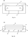
- Figs. 1a and 1b show a schematic top and side view, respectively, of a multipass cell 100 according to an embodiment of the invention.
- the multipass cell 100 comprises a body 10.
- the body 10 is made of a suitable material, in an embodiment material such as plastic, glass, metal or composite materials or a composition comprising several materials.
- a cavity 20 is formed in the body 10 of the multipass cell 100.
- the cavity 20 has a rectangular form. In a further embodiment the cavity is thinner in the middle than at the ends thereof in order to minimize the volume thereof.
- the multipass cell 100 further comprises a first mirror 30a and a second mirror 30b at opposite ends of the cavity 20, i.e. the first mirror 30a at a first end and the second mirror 30b at the other, opposite, end.
- the first and second mirrors 30a, 30b comprise concave spherical, toroidal, or cylindrical mirrors.
- the mirrors 30a, 30b are positioned parallel to each other and perpendicular to the centerline of the cavity 20.
- the first and/or the second mirror is tilted with respect to the other mirror and/or with respect to a cross-sectional axis of the cavity 20.
- the mirrors 30a, 30b in an embodiment comprise materials such as dielectric material, aluminium and copper and are in an embodiment coated, e.g. with gold, silver or with a coating applied by thin film technology, to improve reflectivity.
- the mirrors 30a, 30b are easy to manufacture with high optical quality and cost-effectively.
- the multipass cell 100 further comprises a first channel 40 and a second channel 50 configured to allow electromagnetic radiation, in an embodiment UV, visible or infrared light such as a laser beam, to enter and exit the cavity 20.
- the first 40 and second 50 channel are positioned on the same side of the cavity 20 as shown in Fig. 1a .
- the first 40 and second 50 channel are positioned on opposite corners of the cavity 20.
- the first 40 and second 50 channel are positioned at the same end of the cavity 20 on opposite sides thereof.
- the multipass cell 100 comprises only a single channel configured to allow light to enter and exit the cavity 20.
- the multipass cell 100 comprises a channel on each corner of the cavity.
- the first 30a and second 30b mirror and the first channel 40 are aligned in such a way that a beam, such as a beam of infrared laser, entering the cavity through the first channel 40 next to the outer edge of the first mirror 30a hits the second mirror 30b next to the opposite edge thereof.
- the first 30a and the second 30b mirror are positioned at a distance corresponding to twice the radius of curvature of the first 30a and the second 30b mirror in such way that the beam is focused between the first 30a and the second 30b mirror.
- the first 30a and second 30b mirror are configured to reflect the beam entering the cavity next to an outer edge of the first 30a or the second 30b mirror a predetermined number of times so that the beam propagates substantially in a single plane between the first and the second mirror 30a, 30b and forms a substantially linear reflection spot pattern on the first 30a and the second 30b mirror.
- the beam propagates in the cavity 20 prior to the first reflection from the first or second mirror 30a, 30b and after the last reflection from the first or second mirror 30a, 30b substantially in the same single plane.
- the beam exits the cavity next to the outer edge of the first 30a or the second 30b mirror depending on the position of the second channel 50.
- the number of reflections and the exit position depends on the alignment of the mirrors and the optical parameters thereof. In the following the propagation of a beam in the multipass cell 100 is explained further with reference to Figs 2 to 6 .
- Fig. 2 shows a schematic principle view of a multipass cell according to an embodiment of the invention.
- a beam 200 enters the cavity 20 just outside the edge of the first mirror 30a and hits the opposite edge of the second mirror 30b.
- the first 30a and second 30b mirror are configured to reflect the beam entering the cavity next to an outer edge of the first 30a or the second 30b mirror a predetermined number of times so that the beam 200 propagates substantially in a single plane between the first and the second mirror 30a, 30b and forms a substantially linear reflection spot pattern on the first 30a and the second 30b mirror.
- the beam 200 exits the cavity just outside the edge of the second mirror 30b on the same side of the cavity from which it entered.
- Fig. 3 shows a further schematic principle view of a multipass cell according to an embodiment of the invention.
- a beam 300 enters the cavity 20 just outside the edge of the first mirror 30a and hits the opposite edge of the second mirror 30b.
- the first 30a and second 30b mirror are configured to reflect the beam entering the cavity next to an outer edge of the first 30a or the second 30b mirror a predetermined number of times so that the beam 300 propagates substantially in a single plane between the first and the second mirror 30a, 30b and forms a substantially linear reflection spot pattern on the first 30a and the second 30b mirror.
- the beam 300 exits the cavity just outside the edge of the second mirror 30b on the opposite side of the cavity from which it entered.
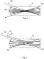
- Fig. 4 shows a further schematic principle view of a multipass cell according to an embodiment of the invention.
- a beam 400 enters the cavity 20 just outside the edge of the first mirror 30a and hits the opposite edge of the second mirror 30b.
- the first 30a and second 30b mirror are configured to reflect the beam entering the cavity next to an outer edge of the first 30a or the second 30b mirror a predetermined number of times so that the beam 400 propagates substantially in a single plane between the first and the second mirror 30a, 30b and forms a substantially linear reflection spot pattern on the first 30a and the second 30b mirror.
- the beam 400 exits the cavity just outside the edge of the first mirror 30a on the opposite side of the cavity from which it entered.
- Fig. 5 shows a further schematic principle view of a multipass cell according to an embodiment of the invention.
- a beam 500 enters the cavity 20 just outside the edge of the first mirror 30a and hits the opposite edge of the second mirror 30b.
- the first 30a and second 30b mirror are configured to reflect the beam entering the cavity next to an outer edge of the first 30a or the second 30b mirror a predetermined number of times so that the beam 500 propagates substantially in a single plane between the first and the second mirror 30a, 30b and forms a substantially linear reflection spot pattern on the first 30a and the second 30b mirror.
- the beam 500 exits the cavity just outside the edge of the first mirror 30a on the same side of the cavity from which it entered.
- the multipass cell 100 further comprises an optical element 90, such as a beamsplitter or a mirror, configured to reflect the light exiting the cavity 20 into a desired direction, for example away from the source of the beam 500 towards e.g. a detector element.
- an optical element 90 such as a beamsplitter or a mirror, configured to reflect the light exiting the cavity 20 into a desired direction, for example away from the source of the beam 500 towards e.g. a detector element.
- Fig. 6 shows a schematic principle view of reflection spot patterns of a multipass cell according to an embodiment of the invention.
- Fig 6 shows only the first mirror 30a with two example forms thereof.
- the first 30a and second 30b mirror are configured to reflect the beam entering the cavity next to an outer edge of the first 30a or the second 30b mirror a predetermined number of times so that the beam propagates substantially in a single plane between the first and the second mirror 30a, 30b and forms a substantially linear reflection spot pattern on the first 30a and the second 30b mirror.
- the cavity 20 need not have a large height, i.e. volume, as the beam propagation does not require height in comparison with traditional multipass cells with an elliptic reflection spot pattern.
- the number of reflections, and accordingly the optical pathlength attained depends on the alignment of the mirrors 30a, 30b, the optical parameters of the mirrors 30a, 30b and the size of the cavity 20, as well as the entry angle of the beam 200.
- the number of reflections is accordingly chosen in accordance with the use of the multipass cell, i.e. the needed pathlength and the size of the cavity required.
- the minimum size of the cavity is somewhat limited by diffraction depending on the wavelength of the used radiation.
- An example minimum length of the cavity 20 is for example with mid-infrared radiation, i.e. wavelengths of about 3 to 5 ⁇ m, approximately from 10 ⁇ m to 100 ⁇ m.
- the minimum height of the cavity is in the region of a few millimeters, for example 2 millimeters.
- Fig. 7 shows a schematic top view of an optical detection system 700 according to an embodiment of the invention.
- the optical detection system is a laser spectrometer.
- the optical detection system is a laser absorption spectrometer.
- the optical detection system is a photoacoustic detector.
- the optical detection system 700 comprises a multipass cell 100 as hereinbefore described with reference to Figs. 1a to 6 .
- the optical detection system 700 further comprises a source 110, for example a laser source configured to direct a beam into the cavity 20.
- the source 110 comprises a tunable laser source, for example a mid-range infrared source, configured to direct a laser beam with adjustable frequency into the cavity 20 via the channel 40.
- the laser source 110 is of a conventional type.
- the laser source comprises a light emitting diode instead of a laser source.
- the optical detection system 700 comprises several sources configured to direct a beam into the cavity 20 via a single or several channels.
- the optical detection system 700 further comprises a detector element 120 configured to receive the beam exiting the cavity 20 via the channel 50.
- the detector element 120 comprises in an embodiment photodetectors and reference photodetectors and an interferometer.
- the detector element 120 is of a conventional type.
- the source 110 is configured to function as the detector element as well using e.g. so called self-mixing technique.
- the detector element 120 comprises an acoustic detection arrangement for photoacoustic detection configured to receive the acoustic signal generated by light absorption in the cavity 20.
- the optical detection system 700 with the multipass cell 100 according to the invention is used for example in absorption laser spectrometry for detecting isotopes in a gas. In such an application a small sample volume with large pathlength is required with small interferences.
- the optical detection system 700 with the multipass cell 100 is used in detecting temporal variations of concentration in which large sample exchange rates possible due to the small volume of the cavity 20 are required.
- the absorption laser spectrometry 700 with the multipass cell 100 is used in studying sample containing only a few molecules of the substance to be detected, which detection is possible due to the small amount of sample required as the volume of the cavity 20 is small and the pathlength large.
- the multipass cell 100 according to the invention is scaled in such a way that it is installed in a handheld device, such as a mobile communications device, which is possible due to the small volume of the cavity 20.
- a technical effect of one or more of the example embodiments disclosed herein is a simple alignment of the mirrors, i.e. the adjustment of distance and tilt thereof is straightforward.
- Another technical effect of one or more of the example embodiments disclosed herein is a robust multipass cell not sensitive to slight misalignment.
- Another technical effect of one or more of the example embodiments disclosed herein is a cost-effective multipass cell with components being easy to manufacture with high optical quality.
- a still further technical effect of one or more of the example embodiments disclosed herein is scalability, i.e. the provision of large pathlength in small volume.
Landscapes
- Physics & Mathematics (AREA)
- General Physics & Mathematics (AREA)
- Analytical Chemistry (AREA)
- Health & Medical Sciences (AREA)
- Life Sciences & Earth Sciences (AREA)
- Chemical & Material Sciences (AREA)
- Biochemistry (AREA)
- General Health & Medical Sciences (AREA)
- Immunology (AREA)
- Pathology (AREA)
- Optics & Photonics (AREA)
- Spectroscopy & Molecular Physics (AREA)
- Acoustics & Sound (AREA)
- Investigating Or Analysing Materials By Optical Means (AREA)
- Optical Measuring Cells (AREA)
Claims (11)
- Multipass-Zelle (100), umfassendeinen Körper (10);einen in dem Körper (10) gebildeten Hohlraum (20);mindestens einen ersten Kanal (40), der so konfiguriert ist, dass ein Strahl in den Hohlraum (20) eintreten kann;einen ersten konkaven sphärischen oder toroidalen Spiegel (30a) an einem ersten Ende des Hohlraums (20); undeinen zweiten konkaven sphärischen oder toroidalen Spiegel (30b) an dem gegenüberliegenden Ende des Hohlraums; wobeider erste Spiegel (30a) und der zweite Spiegel (30b) so konfiguriert sind, dass sie einen Strahl, der etwas außerhalb einer äußeren Kante des ersten (30a) oder des zweiten (30b) Spiegels durch den ersten Kanal (40) in den Hohlraum eintritt, eine vorbestimmte Anzahl von Malen reflektieren, so dass sich der Strahl im Wesentlichen in einer einzigen Ebene zwischen dem ersten (30a) und dem zweiten (30b) Spiegel ausbreitet, bildend ein im Wesentlichen lineares Reflexionsstellenmuster auf dem ersten (30a) und dem zweiten (30b) Spiegel; und wobeider erste Spiegel und der zweite Spiegel in einem Abstand, der dem doppelten Krümmungsradius des ersten (30a) und des zweiten (30b) Spiegels entspricht, auf solch eine Weise angeordnet sind, dass der Strahl zwischen dem ersten und dem zweiten Spiegel fokussiert wird; und wobeider Hohlraum (20) eine rechteckige Form aufweist.
- Multipass-Zelle (100) nach Anspruch 1, wobei der erste Spiegel (30a) und der zweite Spiegel (30b) auf solch eine Weise konfiguriert sind, dass sich der Strahl vor der ersten Reflexion von dem ersten (30a) oder zweiten (30b) Spiegel und nach der letzten Reflexion von dem ersten (30a) oder zweiten (30b) Spiegel im Wesentlichen in derselben einzigen Ebene ausbreitet.
- Multipass-Zelle (100) nach Anspruch 1 oder 2, ferner umfassend mindestens einen zweiten Kanal (50), der so konfiguriert ist, dass ein Strahl den Hohlraum (20) verlassen kann.
- Multipass-Zelle (100) nach einem der vorhergehenden Ansprüche, ferner umfassend Mittel zum Einführen einer Probe in den Hohlraum (20).
- Multipass-Zelle (100) nach Anspruch 4, wobei die Mittel zum Einführen einer Probe in den Hohlraum (20) einen Fluideinlass (60) Kanal und einen Fluidauslass (70) umfassen.
- Multipass-Zelle (100) nach einem der vorhergehenden Ansprüche, ferner umfassend eine Abdeckung (80), die so konfiguriert ist, dass sie den Hohlraum (20) abdeckt.
- Multipass-Zelle (100) nach Anspruch 6, wenn sie von Anspruch 4 abhängig ist, wobei die Mittel zum Einführen einer Probe in den Hohlraum (20) Perforationen und / oder poröses Material in der Abdeckung (80) umfassen.
- Multipass-Zelle (100) nach einem der vorhergehenden Ansprüche, wobei der Hohlraum (20) in der Mitte dünner als an seinen Enden ist.
- Optisches Detektionssystem, umfassend:die Multipass-Zelle nach einem der vorhergehenden Ansprüche,eine optische Quelle (110), die so konfiguriert ist, dass sie einen Strahl in den Hohlraum (20) richtet; undein Detektorelement (120), das so konfiguriert ist, dass es den aus dem Hohlraum (20) austretenden Strahl empfängt, oder so konfiguriert ist, dass es das durch Lichtabsorption in dem Hohlraum (20) erzeugte akustische Signal empfängt.
- Optisches Detektionssystem nach Anspruch 9, wobei die optische Quelle eine abstimmbare Laserquelle umfasst, die so konfiguriert ist, dass sie einen Laserstrahl mit einstellbarer Frequenz oder modulierter Intensität in den Hohlraum (20) richtet.
- Optisches Detektionssystem nach Anspruch 9 oder 10, wobei das optische Detektionssystem ein Laserabsorptionsspektrometer oder einen photoakustischen Detektor umfasst.
Applications Claiming Priority (2)
| Application Number | Priority Date | Filing Date | Title |
|---|---|---|---|
| FI20155833A FI129342B (en) | 2015-11-11 | 2015-11-11 | Multipass cell with small volume |
| PCT/FI2016/050774 WO2017081363A1 (en) | 2015-11-11 | 2016-11-03 | Low volume multipass cell |
Publications (4)
| Publication Number | Publication Date |
|---|---|
| EP3380824A1 EP3380824A1 (de) | 2018-10-03 |
| EP3380824A4 EP3380824A4 (de) | 2019-04-17 |
| EP3380824B1 true EP3380824B1 (de) | 2025-01-08 |
| EP3380824C0 EP3380824C0 (de) | 2025-01-08 |
Family
ID=58694750
Family Applications (1)
| Application Number | Title | Priority Date | Filing Date |
|---|---|---|---|
| EP16863728.8A Active EP3380824B1 (de) | 2015-11-11 | 2016-11-03 | Kleinvolumige multipass-zelle |
Country Status (4)
| Country | Link |
|---|---|
| US (1) | US10337981B2 (de) |
| EP (1) | EP3380824B1 (de) |
| FI (1) | FI129342B (de) |
| WO (1) | WO2017081363A1 (de) |
Families Citing this family (9)
| Publication number | Priority date | Publication date | Assignee | Title |
|---|---|---|---|---|
| FI127556B (en) | 2017-02-06 | 2018-09-14 | Teknologian Tutkimuskeskus Vtt Oy | Method and Device for Respiratory Analysis |
| JP2019074434A (ja) * | 2017-10-17 | 2019-05-16 | 日本無線株式会社 | 検体診断装置 |
| CN109407310B (zh) * | 2018-12-09 | 2020-07-10 | 山西大学 | 一种多通池的设计方法 |
| GB2587418B (en) * | 2019-09-30 | 2022-02-09 | Oxford Highq Ltd | Sensor including an optical microcavity on a unitary structure |
| GB2587420B (en) * | 2019-09-30 | 2021-11-03 | Oxford Highq Ltd | Optical microcavity device, alignment structure for an optical device, and method for aligning an optical device |
| EP3974808A1 (de) * | 2020-09-25 | 2022-03-30 | MIRO Analytical AG | Vorrichtung und verfahren zur gasanalyse |
| EP4019938A1 (de) * | 2020-12-22 | 2022-06-29 | Fraunhofer-Gesellschaft zur Förderung der angewandten Forschung e.V. | Fluidmesszelle für einen photoakustischen sensor |
| CN119757227A (zh) * | 2024-12-06 | 2025-04-04 | 国网安徽省电力有限公司电力科学研究院 | 一种用于气体绝缘设备的光纤光声气体传感系统及方法 |
| CN119757226A (zh) * | 2024-12-06 | 2025-04-04 | 国网安徽省电力有限公司电力科学研究院 | 用于气体绝缘设备的线型光斑多通式光纤光声气体传感器 |
Citations (1)
| Publication number | Priority date | Publication date | Assignee | Title |
|---|---|---|---|---|
| EP2904377A1 (de) * | 2012-10-08 | 2015-08-12 | EMPA Eidgenössische Materialprüfungs- und Forschungsanstalt | Verfahren zur reduzierung von interferenzstreifen bei laserspektroskopiemessungen mittels einer absorptionsmaske in kombination mit mehrflutigen optischen zellen |
Family Cites Families (18)
| Publication number | Priority date | Publication date | Assignee | Title |
|---|---|---|---|---|
| GB1168717A (en) | 1967-06-16 | 1969-10-29 | Zeiss Jena Veb Carl | Optical Multiple-Reflection System. |
| US4189646A (en) * | 1977-05-12 | 1980-02-19 | Vanderleeden Johannes C | Process and apparatus for reacting laser radiation with a reactive medium |
| JP2560362B2 (ja) | 1987-12-18 | 1996-12-04 | 富士通株式会社 | 多重反射鏡 |
| US5121988A (en) * | 1989-10-04 | 1992-06-16 | Tsi Incorporated | Single particle detector method and apparatus utilizing light extinction within a sheet of light |
| WO1994024545A1 (en) | 1993-04-15 | 1994-10-27 | Board Of Regents, The University Of Texas System | Raman spectrometer |
| JPH0843305A (ja) | 1994-07-29 | 1996-02-16 | Nippon Kagaku Kogyo Kk | 煙濃度測定装置 |
| US5993549A (en) * | 1996-01-19 | 1999-11-30 | Deutsche Forschungsanstalt Fuer Luft- Und Raumfahrt E.V. | Powder coating apparatus |
| US20010051118A1 (en) | 1999-07-21 | 2001-12-13 | Ronald J. Mosso | Particle production apparatus |
| US6067840A (en) | 1997-08-04 | 2000-05-30 | Texas Instruments Incorporated | Method and apparatus for infrared sensing of gas |
| FR2767195A1 (fr) | 1997-12-15 | 1999-02-12 | Commissariat Energie Atomique | Cuve d'absorption pour systeme d'analyse de gaz |
| US6563583B2 (en) | 2000-10-12 | 2003-05-13 | Amnis Corporation | Multipass cavity for illumination and excitation of moving objects |
| JP3638261B2 (ja) | 2001-08-03 | 2005-04-13 | 日本カノマックス株式会社 | 煙濃度測定装置 |
| DE10216047A1 (de) | 2002-04-11 | 2003-10-23 | Univ Albert Ludwigs Freiburg | Monolithische Multi-Pass-Zelle |
| GB2389177B (en) | 2002-05-31 | 2006-03-15 | Marconi Applied Techn Ltd | Gas sensors |
| DE102007014518B3 (de) | 2007-03-27 | 2008-11-13 | Fraunhofer-Gesellschaft zur Förderung der angewandten Forschung e.V. | Photoakustische Multipass-Zelle mit konzentrierenden Reflexionsmitteln |
| US7876443B2 (en) | 2008-09-29 | 2011-01-25 | Battelle Memorial Institute | Multipass optical device and process for gas and analyte determination |
| CN104122223B (zh) | 2014-08-07 | 2017-02-08 | 中国科学院上海微系统与信息技术研究所 | 一种双光程多气体红外气体传感器 |
| US20170356842A1 (en) * | 2016-06-09 | 2017-12-14 | Adelphi University | Real-time trace gas sensor using a multi-mode diode laser and multiple line integrated cavity enhanced absorption spectroscopy |
-
2015
- 2015-11-11 FI FI20155833A patent/FI129342B/en active IP Right Grant
-
2016
- 2016-11-03 WO PCT/FI2016/050774 patent/WO2017081363A1/en not_active Ceased
- 2016-11-03 EP EP16863728.8A patent/EP3380824B1/de active Active
- 2016-11-03 US US15/775,415 patent/US10337981B2/en active Active
Patent Citations (1)
| Publication number | Priority date | Publication date | Assignee | Title |
|---|---|---|---|---|
| EP2904377A1 (de) * | 2012-10-08 | 2015-08-12 | EMPA Eidgenössische Materialprüfungs- und Forschungsanstalt | Verfahren zur reduzierung von interferenzstreifen bei laserspektroskopiemessungen mittels einer absorptionsmaske in kombination mit mehrflutigen optischen zellen |
Also Published As
| Publication number | Publication date |
|---|---|
| US10337981B2 (en) | 2019-07-02 |
| US20180372616A1 (en) | 2018-12-27 |
| FI129342B (en) | 2021-12-15 |
| EP3380824C0 (de) | 2025-01-08 |
| EP3380824A4 (de) | 2019-04-17 |
| FI20155833A7 (fi) | 2017-05-12 |
| EP3380824A1 (de) | 2018-10-03 |
| WO2017081363A1 (en) | 2017-05-18 |
Similar Documents
| Publication | Publication Date | Title |
|---|---|---|
| US10337981B2 (en) | Low volume multipass cell | |
| US7777887B2 (en) | Absorption spectroscopy apparatus and method | |
| US7869036B2 (en) | Analysis apparatus for analyzing a specimen by obtaining electromagnetic spectrum information | |
| US20070145236A1 (en) | Photosensing throughout energy range and in subranges | |
| US10739198B2 (en) | System for analyzing electromagnetic radiation, and device for producing same | |
| AU2016314503B2 (en) | Spectrograph | |
| US20160061660A1 (en) | Miniature spectrometer and apparatus employing same | |
| EP3532823A1 (de) | Gasdetektorsystem mit ringreflektor | |
| EP2904377B1 (de) | Verfahren zur reduzierung von interferenzstreifen bei laserspektroskopiemessungen mittels einer absorptionsmaske in kombination mit mehrflutigen optischen zellen | |
| WO2016166872A1 (ja) | フーリエ変換型分光光度計 | |
| CN108020516A (zh) | 光谱仪或成像光谱仪 | |
| CN100595568C (zh) | 光学分析仪 | |
| CN110632058A (zh) | 一种用于拉曼光谱分析的小型分光装置 | |
| US11674888B2 (en) | Self-aligned high finesse optical sensor cell | |
| KR101606785B1 (ko) | 기체 분석용 테라헤르츠 분광기 | |
| US10760968B2 (en) | Spectrometric measuring device | |
| CN101379391B (zh) | 用于测量薄片性质的光学扫描仪 | |
| CN101451952B (zh) | 实现宽带光谱表面等离子体共振的方法 | |
| CN114755187B (zh) | 高分辨率拉曼光谱仪 | |
| WO2019116461A1 (ja) | 遠赤外光源、遠赤外分光装置 | |
| JP5371295B2 (ja) | 電磁波の分析装置 | |
| US12072281B2 (en) | Multipass optical spectroscopy cell having a single transmission path | |
| CN212059104U (zh) | 一种宽光谱高灵敏度拉曼光谱仪 | |
| JPH0480330B2 (de) | ||
| JP3469569B2 (ja) | フローセル |
Legal Events
| Date | Code | Title | Description |
|---|---|---|---|
| STAA | Information on the status of an ep patent application or granted ep patent |
Free format text: STATUS: THE INTERNATIONAL PUBLICATION HAS BEEN MADE |
|
| PUAI | Public reference made under article 153(3) epc to a published international application that has entered the european phase |
Free format text: ORIGINAL CODE: 0009012 |
|
| STAA | Information on the status of an ep patent application or granted ep patent |
Free format text: STATUS: REQUEST FOR EXAMINATION WAS MADE |
|
| 17P | Request for examination filed |
Effective date: 20180529 |
|
| AK | Designated contracting states |
Kind code of ref document: A1 Designated state(s): AL AT BE BG CH CY CZ DE DK EE ES FI FR GB GR HR HU IE IS IT LI LT LU LV MC MK MT NL NO PL PT RO RS SE SI SK SM TR |
|
| AX | Request for extension of the european patent |
Extension state: BA ME |
|
| DAV | Request for validation of the european patent (deleted) | ||
| DAX | Request for extension of the european patent (deleted) | ||
| A4 | Supplementary search report drawn up and despatched |
Effective date: 20190319 |
|
| RIC1 | Information provided on ipc code assigned before grant |
Ipc: G01N 29/02 20060101ALN20190311BHEP Ipc: G01N 21/39 20060101ALN20190311BHEP Ipc: G01N 29/24 20060101ALN20190311BHEP Ipc: G01N 21/17 20060101ALN20190311BHEP Ipc: G01N 21/03 20060101AFI20190311BHEP Ipc: G01N 21/3504 20140101ALN20190311BHEP |
|
| STAA | Information on the status of an ep patent application or granted ep patent |
Free format text: STATUS: EXAMINATION IS IN PROGRESS |
|
| 17Q | First examination report despatched |
Effective date: 20210713 |
|
| GRAP | Despatch of communication of intention to grant a patent |
Free format text: ORIGINAL CODE: EPIDOSNIGR1 |
|
| STAA | Information on the status of an ep patent application or granted ep patent |
Free format text: STATUS: GRANT OF PATENT IS INTENDED |
|
| RIC1 | Information provided on ipc code assigned before grant |
Ipc: G01N 21/17 20060101ALN20240313BHEP Ipc: G01N 21/3504 20140101ALN20240313BHEP Ipc: G01N 29/24 20060101ALI20240313BHEP Ipc: G01N 29/02 20060101ALI20240313BHEP Ipc: G01N 21/39 20060101ALI20240313BHEP Ipc: G01N 21/03 20060101AFI20240313BHEP |
|
| INTG | Intention to grant announced |
Effective date: 20240402 |
|
| GRAJ | Information related to disapproval of communication of intention to grant by the applicant or resumption of examination proceedings by the epo deleted |
Free format text: ORIGINAL CODE: EPIDOSDIGR1 |
|
| STAA | Information on the status of an ep patent application or granted ep patent |
Free format text: STATUS: EXAMINATION IS IN PROGRESS |
|
| GRAP | Despatch of communication of intention to grant a patent |
Free format text: ORIGINAL CODE: EPIDOSNIGR1 |
|
| STAA | Information on the status of an ep patent application or granted ep patent |
Free format text: STATUS: GRANT OF PATENT IS INTENDED |
|
| INTC | Intention to grant announced (deleted) | ||
| RIC1 | Information provided on ipc code assigned before grant |
Ipc: G01N 21/17 20060101ALN20240801BHEP Ipc: G01N 21/3504 20140101ALN20240801BHEP Ipc: G01N 29/24 20060101ALI20240801BHEP Ipc: G01N 29/02 20060101ALI20240801BHEP Ipc: G01N 21/39 20060101ALI20240801BHEP Ipc: G01N 21/03 20060101AFI20240801BHEP |
|
| INTG | Intention to grant announced |
Effective date: 20240808 |
|
| GRAS | Grant fee paid |
Free format text: ORIGINAL CODE: EPIDOSNIGR3 |
|
| GRAA | (expected) grant |
Free format text: ORIGINAL CODE: 0009210 |
|
| STAA | Information on the status of an ep patent application or granted ep patent |
Free format text: STATUS: THE PATENT HAS BEEN GRANTED |
|
| AK | Designated contracting states |
Kind code of ref document: B1 Designated state(s): AL AT BE BG CH CY CZ DE DK EE ES FI FR GB GR HR HU IE IS IT LI LT LU LV MC MK MT NL NO PL PT RO RS SE SI SK SM TR |
|
| RAP3 | Party data changed (applicant data changed or rights of an application transferred) |
Owner name: TEKNOLOGIAN TUTKIMUSKESKUS VTT OY |
|
| REG | Reference to a national code |
Ref country code: GB Ref legal event code: FG4D |
|
| REG | Reference to a national code |
Ref country code: CH Ref legal event code: EP |
|
| REG | Reference to a national code |
Ref country code: DE Ref legal event code: R096 Ref document number: 602016090916 Country of ref document: DE |
|
| REG | Reference to a national code |
Ref country code: IE Ref legal event code: FG4D |
|
| U01 | Request for unitary effect filed |
Effective date: 20250110 |
|
| U07 | Unitary effect registered |
Designated state(s): AT BE BG DE DK EE FI FR IT LT LU LV MT NL PT RO SE SI Effective date: 20250116 |
|
| PG25 | Lapsed in a contracting state [announced via postgrant information from national office to epo] |
Ref country code: RS Free format text: LAPSE BECAUSE OF FAILURE TO SUBMIT A TRANSLATION OF THE DESCRIPTION OR TO PAY THE FEE WITHIN THE PRESCRIBED TIME-LIMIT Effective date: 20250408 |
|
| PG25 | Lapsed in a contracting state [announced via postgrant information from national office to epo] |
Ref country code: PL Free format text: LAPSE BECAUSE OF FAILURE TO SUBMIT A TRANSLATION OF THE DESCRIPTION OR TO PAY THE FEE WITHIN THE PRESCRIBED TIME-LIMIT Effective date: 20250108 |
|
| PG25 | Lapsed in a contracting state [announced via postgrant information from national office to epo] |
Ref country code: ES Free format text: LAPSE BECAUSE OF FAILURE TO SUBMIT A TRANSLATION OF THE DESCRIPTION OR TO PAY THE FEE WITHIN THE PRESCRIBED TIME-LIMIT Effective date: 20250108 |
|
| PG25 | Lapsed in a contracting state [announced via postgrant information from national office to epo] |
Ref country code: NO Free format text: LAPSE BECAUSE OF FAILURE TO SUBMIT A TRANSLATION OF THE DESCRIPTION OR TO PAY THE FEE WITHIN THE PRESCRIBED TIME-LIMIT Effective date: 20250408 Ref country code: IS Free format text: LAPSE BECAUSE OF FAILURE TO SUBMIT A TRANSLATION OF THE DESCRIPTION OR TO PAY THE FEE WITHIN THE PRESCRIBED TIME-LIMIT Effective date: 20250508 |
|
| PG25 | Lapsed in a contracting state [announced via postgrant information from national office to epo] |
Ref country code: HR Free format text: LAPSE BECAUSE OF FAILURE TO SUBMIT A TRANSLATION OF THE DESCRIPTION OR TO PAY THE FEE WITHIN THE PRESCRIBED TIME-LIMIT Effective date: 20250108 |
|
| PG25 | Lapsed in a contracting state [announced via postgrant information from national office to epo] |
Ref country code: GR Free format text: LAPSE BECAUSE OF FAILURE TO SUBMIT A TRANSLATION OF THE DESCRIPTION OR TO PAY THE FEE WITHIN THE PRESCRIBED TIME-LIMIT Effective date: 20250409 |
|
| PG25 | Lapsed in a contracting state [announced via postgrant information from national office to epo] |
Ref country code: SM Free format text: LAPSE BECAUSE OF FAILURE TO SUBMIT A TRANSLATION OF THE DESCRIPTION OR TO PAY THE FEE WITHIN THE PRESCRIBED TIME-LIMIT Effective date: 20250108 |
|
| PG25 | Lapsed in a contracting state [announced via postgrant information from national office to epo] |
Ref country code: CZ Free format text: LAPSE BECAUSE OF FAILURE TO SUBMIT A TRANSLATION OF THE DESCRIPTION OR TO PAY THE FEE WITHIN THE PRESCRIBED TIME-LIMIT Effective date: 20250108 |
|
| PG25 | Lapsed in a contracting state [announced via postgrant information from national office to epo] |
Ref country code: SK Free format text: LAPSE BECAUSE OF FAILURE TO SUBMIT A TRANSLATION OF THE DESCRIPTION OR TO PAY THE FEE WITHIN THE PRESCRIBED TIME-LIMIT Effective date: 20250108 |
|
| PLBE | No opposition filed within time limit |
Free format text: ORIGINAL CODE: 0009261 |
|
| STAA | Information on the status of an ep patent application or granted ep patent |
Free format text: STATUS: NO OPPOSITION FILED WITHIN TIME LIMIT |
|
| 26N | No opposition filed |
Effective date: 20251009 |
|
| U20 | Renewal fee for the european patent with unitary effect paid |
Year of fee payment: 10 Effective date: 20251127 |
|
| PGFP | Annual fee paid to national office [announced via postgrant information from national office to epo] |
Ref country code: GB Payment date: 20251121 Year of fee payment: 10 |