EP3380347B1 - Process of operating the air conditioning system of a cab of a machine - Google Patents
Process of operating the air conditioning system of a cab of a machine Download PDFInfo
- Publication number
- EP3380347B1 EP3380347B1 EP16802022.0A EP16802022A EP3380347B1 EP 3380347 B1 EP3380347 B1 EP 3380347B1 EP 16802022 A EP16802022 A EP 16802022A EP 3380347 B1 EP3380347 B1 EP 3380347B1
- Authority
- EP
- European Patent Office
- Prior art keywords
- air
- cab
- conditioning system
- process according
- flow
- Prior art date
- Legal status (The legal status is an assumption and is not a legal conclusion. Google has not performed a legal analysis and makes no representation as to the accuracy of the status listed.)
- Active
Links
Images




Classifications
-
- B—PERFORMING OPERATIONS; TRANSPORTING
- B60—VEHICLES IN GENERAL
- B60H—ARRANGEMENTS OF HEATING, COOLING, VENTILATING OR OTHER AIR-TREATING DEVICES SPECIALLY ADAPTED FOR PASSENGER OR GOODS SPACES OF VEHICLES
- B60H1/00—Heating, cooling or ventilating devices
- B60H1/00357—Air-conditioning arrangements specially adapted for particular vehicles
- B60H1/00378—Air-conditioning arrangements specially adapted for particular vehicles for tractor or load vehicle cabins
-
- B—PERFORMING OPERATIONS; TRANSPORTING
- B60—VEHICLES IN GENERAL
- B60H—ARRANGEMENTS OF HEATING, COOLING, VENTILATING OR OTHER AIR-TREATING DEVICES SPECIALLY ADAPTED FOR PASSENGER OR GOODS SPACES OF VEHICLES
- B60H1/00—Heating, cooling or ventilating devices
- B60H1/00642—Control systems or circuits; Control members or indication devices for heating, cooling or ventilating devices
- B60H1/00735—Control systems or circuits characterised by their input, i.e. by the detection, measurement or calculation of particular conditions, e.g. signal treatment, dynamic models
-
- B—PERFORMING OPERATIONS; TRANSPORTING
- B60—VEHICLES IN GENERAL
- B60H—ARRANGEMENTS OF HEATING, COOLING, VENTILATING OR OTHER AIR-TREATING DEVICES SPECIALLY ADAPTED FOR PASSENGER OR GOODS SPACES OF VEHICLES
- B60H1/00—Heating, cooling or ventilating devices
- B60H1/00642—Control systems or circuits; Control members or indication devices for heating, cooling or ventilating devices
- B60H1/00735—Control systems or circuits characterised by their input, i.e. by the detection, measurement or calculation of particular conditions, e.g. signal treatment, dynamic models
- B60H1/008—Control systems or circuits characterised by their input, i.e. by the detection, measurement or calculation of particular conditions, e.g. signal treatment, dynamic models the input being air quality
-
- B—PERFORMING OPERATIONS; TRANSPORTING
- B60—VEHICLES IN GENERAL
- B60H—ARRANGEMENTS OF HEATING, COOLING, VENTILATING OR OTHER AIR-TREATING DEVICES SPECIALLY ADAPTED FOR PASSENGER OR GOODS SPACES OF VEHICLES
- B60H1/00—Heating, cooling or ventilating devices
- B60H1/00642—Control systems or circuits; Control members or indication devices for heating, cooling or ventilating devices
- B60H1/00814—Control systems or circuits characterised by their output, for controlling particular components of the heating, cooling or ventilating installation
- B60H1/00821—Control systems or circuits characterised by their output, for controlling particular components of the heating, cooling or ventilating installation the components being ventilating, air admitting or air distributing devices
- B60H1/00835—Damper doors, e.g. position control
- B60H1/00849—Damper doors, e.g. position control for selectively commanding the induction of outside or inside air
-
- E—FIXED CONSTRUCTIONS
- E02—HYDRAULIC ENGINEERING; FOUNDATIONS; SOIL SHIFTING
- E02F—DREDGING; SOIL-SHIFTING
- E02F9/00—Component parts of dredgers or soil-shifting machines, not restricted to one of the kinds covered by groups E02F3/00 - E02F7/00
- E02F9/16—Cabins, platforms, or the like, for drivers
- E02F9/163—Structures to protect drivers, e.g. cabins, doors for cabins; Falling object protection structure [FOPS]; Roll over protection structure [ROPS]
Definitions
- the invention relates to a process of operating the air conditioning system of a cab of a machine, and a machine, in particular an agricultural machine, comprising a cab equipped with an air conditioning system which is adapted to be operated according to such a process.
- such machines are driven by a human operator seating in a closed cab of the driver station for actuating the commands means for moving said machine and/or operating the spreading unit.
- the machine is in particular adapted to be driven by a human operator.
- the driver station comprises a closed cab 1 wherein the operator is intended to seat for actuating the commands means for moving said machine and/or operating the spreading unit.
- central housing 13 is in fluid communication with the lateral housings 14a, 14b, so as to allow the blowing into the exterior branch 9b of an exterior air flow F E that has been filtered by at least one filtering means 11a, 11b.
- each housing 14a, 14b may be provided with a pressure differential sensor S ( figure 4b ) which is connected by sensor lines to the upstream and downstream ends of the respective lateral housings 14a, 14b.
- a pressure differential sensor S figure 4b
- the pressure differential sensor signal is constantly monitored by the sensors S and, upon the pressure differential exceeding a limit value, the operator is warned that the one or the other filtering means 11a, 11b needs replacement, in particular by activating a communication mean such as a lighting indicator button, a screen or speaker(s), implemented in the cab 1.
- the air conditioning system 5 further comprises additional filtering means 19 that may be arranged at the fluid communication path between the interior of the cab 1 and the outlet of the recycling branch 9a, so as to remove possible air pollutants from the recycled air flow coming from said cab interior.
- the additional filtering means 19 are provided at the inlet of the recycling branch 9a.
- the process comprises a filtration mode selection procedure wherein the switching means are operated to select one filtration mode, either upon manual activation of an appropriate means by the operator in the cab 1, for example a button or a switch on a control board within said cab, or upon automatic detection of an appropriate signal corresponding to the actuation state of the spreading unit.
- the process provides for performing the regular procedure upon initial actuation I of the air conditioning system 5, the steps A, B of the filtration mode selection procedure being performed during said regular procedure just after the initial actuation step I.
Landscapes
- Physics & Mathematics (AREA)
- Thermal Sciences (AREA)
- Engineering & Computer Science (AREA)
- Mechanical Engineering (AREA)
- Air-Conditioning For Vehicles (AREA)
Description
- The invention relates to a process of operating the air conditioning system of a cab of a machine, and a machine, in particular an agricultural machine, comprising a cab equipped with an air conditioning system which is adapted to be operated according to such a process.
- It applies in particular to the technical domain of mechanical or pressurized spreading of treatment products, such as phytosanitary products, insecticides or fertilizers, on the harvest plants and/or the plowed soil of an agricultural field, such as a vineyard or an orchard.
- To do so, land agricultural machines are known, comprising a motorized support structure which is equipped with a driver station and movable in particular along rows of plants and/or furrows of an agricultural field, a spreading unit being mounted on said structure for straddling at least one of said rows and spreading determined measures of at least one treatment product on said rows.
- In particular, such machines are driven by a human operator seating in a closed cab of the driver station for actuating the commands means for moving said machine and/or operating the spreading unit.
- Treatment products used in the agricultural domain are generally harmful for the health. In particular, during spreading operations, a quantity of such products may diffuse in the air, in particular in the form of dusts, aerosols and/or vapors, and form air pollutants which, if there are inhaled by the operator, in particular repeatedly, may cause in the long term serious and invalidating professional pulmonary and/or respiratory diseases.
- For limiting the risks of exposure of the operator to such air pollutants, cabs are generally equipped with air conditioning systems that are adapted to condition the air circulating in said cabs, in particular by feeding said cabs with air that is mainly free from such pollutants.
- In particular, such air-conditioning systems are known, comprising:
- a circuit for supplying the cab with air coming from a recycling branch, that is fed with recycled air coming from the interior of said cab, and an exterior branch, that is fed with air coming from the exterior of said cab;
- a blowing device for providing an air flow inside said circuit;
- filtration means for removing pollutants from the air blown in the cab through said circuit;
- Besides, such air-conditioning systems may comply with strict regulatory texts, such as the European standard EN-15695, in particular as regards the air flow debit, the air pressurization inside the cab and the quality of the filtration means. For example, this standard defines four levels or categories for the security provided to the operator, from a minimum security level (category 1) wherein the health risks are minimal, for instance when the machine is driven on a road, to a maximum security level (category 4), wherein said machine is driven on a field to spray highly polluting and volatile products.
- However, these requirements are not totally satisfactory, as they cannot efficiently protect the operator in case of a contamination of the cab with air pollutants as described above. Indeed, when polluted air enters into the cab, for example upon opening of an access of said cab by the operator, said polluted air is difficult and slow to evacuate, in particular as the air provided by the air-conditioning system mainly comprises recycled air coming from said cab, i.e. potentially polluted air.
- A process of operating the air conditioning system of a cab of a machine is known from
document EP 1 908 345 A1 . The invention aims to improve the prior art by proposing a process of operating the air conditioning system of a cab which allows to protect more efficiently the operator from air pollutants diffused around said cab, in particular in the case of contamination of the interior of said cab with said air pollutants. - For that purpose, and according to a first aspect, the invention relates to a process of operating the air conditioning system of a cab of a machine, said air-conditioning system comprising:
- a circuit for supplying said cab with air coming from a recycling branch fed with air coming from the interior of said cab and an exterior branch fed with air coming from the exterior of said cab;
- a blowing device for providing an air flow inside said circuit;
- filtration means for removing pollutants from the air blown in the cab through said circuit;
- increase the flow of air supplied into the cab by the blowing device through the circuit;
- balance said flow of air to supply air coming only from the exterior branch by closing the recycling branch; and
- open an exhaust flap within the cab for increasing the flow of air evacuated from said cab;
- According to a second aspect, the invention relates to a machine, in particular an agricultural machine, comprising a cab equipped with an air conditioning system which is adapted to be operated according to such a process.
- Other aspects and advantages of the invention will become apparent in the following description made with reference to the appended figures, wherein:
-
figure 1 represents schematically in a perspective view a cab of a machine according to the invention; -
figure 2 represents schematically in a partial exploded view the air conditioning system of the cab offigure 1 ,figure 2a representing in a exploded view the filtration and pressurization set of said system with means for switching between first and second filtration modes according to a first embodiment of the invention; -
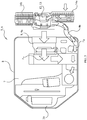
figure 3 represents schematically in a top view the operation of the air-conditioning system offigures 1 ,2 during the regular procedure, said air-conditioning system being arranged in a first filtration mode; -
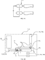
figure 4a represents schematically the steps of the procedure for switching the air conditioning system between the first and second filtration modes,figure 4b representing schematically a filtration and pressurization set with switching means according to a second embodiment of the invention; -
figure 5 represents schematically the steps of a process according to the invention; -
figures 6 represents schematically in a top view the operation of the air conditioning system offigures 1 ,2 which is arranged in a second filtration mode, respectively during the regular procedure (figure 6a ) and during the flushing procedure (figure 6b ). - In relation to those figures, we describe below a machine comprising a cab equipped with an air conditioning system.
- The machine is in particular an agricultural machine arranged for the mechanical or pressurized spreading of treatment products, such as phytosanitary products, insecticides or fertilizers, on the harvest plants and/or the plowed soil of an agricultural field, such as a vineyard or an orchard.
- To do so, the machine comprising a motorized support structure which is equipped with a driver station and movable in particular along rows of plants and/or furrows of an agricultural field, a spreading unit being mounted on said structure for straddling at least one of said rows and spreading determined amounts of at least one treatment product on said rows.
- In particular, the spreading unit can be mounted on the support structure permanently or removably, so as to be replaceable by other equipment and accessories, for example harvesting equipment, pruning equipment or equipment for working the soil.
- The machine is in particular adapted to be driven by a human operator. To do so, the driver station comprises a closed
cab 1 wherein the operator is intended to seat for actuating the commands means for moving said machine and/or operating the spreading unit. - As shown in
figure 1 , thecab 1 comprises afront windshield 2 made from a substantially transparent and solid material, for example laminated glass, for protecting the operator from wind and/or rain while ensuring a good visibility to allow said operator to safely drive and operate the machine, as well as adevice 3 for remotely controlled washing of said windshield, in particular with an adapted product, for removing dirt that can potentially hinder said visibility. Moreover, thecab 1 comprises at least an access, in particular alateral access door 4, for allowing the operator to enter and to leave thecab 1. - Direct contact with treatment products used in the agricultural domain is generally harmful for the health. In particular, during spreading operations, a quantity of such products may diffuse in the air, in particular in the form of dusts, aerosols and/or vapours, and then may form air pollutants which, if they are inhaled by the operator, in particular repeatedly, may cause in the long term serious and invalidating professional pulmonary and/or respiratory diseases.
- For limiting the risk of exposure of the operator to such air pollutants, the
cab 1 is equipped with anair conditioning system 5 that is adapted to condition the air circulating in said cab, in particular by feeding said cab with air that is principally free from such pollutants. - In relation to the figures, the
air conditioning system 5 is implemented in the roof of thecab 1, in particular into a sealedcompartment 6 which is fixed, for example by gluing, underneath said roof, and which is accessible from the exterior of thecab 1 by means of an upperremovable maintenance cover 7. In particular, themaintenance cover 7 comprises a peripheral edge which is equipped with a sealinggasket 8, so as to ensure the sealed closing of thecompartment 6. - In a known manner, the
air conditioning system 5 comprises: - a
control board card 21 for steering the operation of said system, in particular upon communication with command means implemented within thecab 1, according to a predetermined process; - a circuit 9 which supplies the
cab 1 with air coming from a recycling branch 9a fed with air coming from the interior of said cab and anexterior branch 9b fed with air coming from the exterior of said cab; - a blowing
device 10 for providing an air flow inside said circuit; - filtration means 11 for removing pollutants from the air blown in the cab through said circuit.
- With reference to the figures, the
air conditioning system 5 comprises a filtration andpressurization set 12 which is arranged upstream the circuit 9, said set comprising acentral housing 13, wherein the blowingdevice 10 is arranged, and twolateral housings figure 2a , the central 13 and lateral 14a, 14b housings may be constituted by upper 13u, 14au, 14bu and lower 131, 14al, 14bl housing portions to be assembled together to form said housings. Moreover,figures 2a and4b represent schematically a filtration and pressurization set 12 according to respectively an embodiment of the invention. Thelateral housings cab 1, so as to allow circulation through said housings of air coming from said exterior and to remove pollutants from said exterior air by means of the filtration means 11a, 11b arranged within said housings. - Further, the
central housing 13 is in fluid communication with thelateral housings exterior branch 9b of an exterior air flow FE that has been filtered by at least one filtering means 11a, 11b. - The filtering means 11, 11a, 11b may be adapted to remove pollutants to comply with the requirements of at least the
category 2 defined by standard EN-15695 so as to be able to remove at least the dust pollutants from the air flow to be blown into thecab 1, and more particularly with the requirements of themaximum category 4 of said standard, so as to be able to remove not only dusts, but also aerosol and vapour pollutants from said air flow. - In the embodiment shown, the
air conditioning system 5 comprises first 11a and second 11b filtering means that comply with the requirements of respectively thecategories - Moreover, the
air conditioning system 5 comprises means for selectively switching between two filtration modes corresponding respectively tocategory device 10 according to the desired level of filtration. - As shown in
figures 2a and4b , the switching means comprise at least one filter selection valve 15 (figure 2a ), and in particular twoselection valves figure 4b ), said valves being arranged influid communication paths 16 relaying thecentral housing 13 to respectively thefirst category 2 14a and thesecond category 4 14b filtering housings, said valve(s) being operable to be selectively actuated, in particular by means of anactuator 17 to which said valve is linked through a connector (not shown), respectively incategory category 4filtration housing 14b and thecentral housing 13 and open(s) - respectively close(s) - the fluid communication between thecategory 2filtration housing 14a and said central housing. - Thus, in a particularly advantageous manner, the operator can benefit from a high level of filtration only when required, in particular only during the performing of a spreading operation in an agricultural field, and can switch to a lower level of filtration of
category 2 when the risks of air pollution are lower, for example during road transport between an agricultural field and a farm or between fields Such a configuration allows to limit the clogging of thecategory 4 filtering means 11b and to substantially increase its lifetime, which is quite short in relation to the lifetime of approximately 1 year of thecategory 2 filters. - In order to assess the saturation or clogging of the filtering means 11a, 11b, each
housing figure 4b ) which is connected by sensor lines to the upstream and downstream ends of the respectivelateral housings cab 1. - The
air conditioning system 5 further comprises additional filtering means 19 that may be arranged at the fluid communication path between the interior of thecab 1 and the outlet of the recycling branch 9a, so as to remove possible air pollutants from the recycled air flow coming from said cab interior. In the embodiment shown, the additional filtering means 19 are provided at the inlet of the recycling branch 9a. - The
air conditioning system 5 further comprises arecycling valve 27 located in the recycling branch 9a, e.g. downstream of the additional filtering means 19, for selectively opening and closing said recycling branch. - Moreover, the
air conditioning system 5 comprises a HVAC device 20 (for Heating, Ventilation and Air Conditioning) which is arranged downstream of the circuit 9 for conditioning the air flow blown in thecab 1 through said circuit, said HVAC device comprising an inlet into which both of thecircuit branches 9a, 9b end for feeding said HVAC device with the air flow to be conditioned and blown into thecab 1. TheHVAC device 20 comprises heat exchangers for cooling or heating the passing air and a circulation blower for blowing the conditioned air into the interior of thecab 1. - With reference to the figures, we describe now a process of operating the
air conditioning system 5. - In particular, the process comprises a filtration mode selection procedure wherein the switching means are operated to select one filtration mode, either upon manual activation of an appropriate means by the operator in the
cab 1, for example a button or a switch on a control board within said cab, or upon automatic detection of an appropriate signal corresponding to the actuation state of the spreading unit. - More precisely, the filtration mode selection procedure provides a first step A, in which the system assesses whether the
cab 1 is provided with bothcategory 2 andcategory 4 filtering means 11a, 11b and puts theselection valves category 2 filtration mode. Therecycling valve 27 is in its default position, which is the open state to allow the flow FR of interior air through the recycling branch 9a to theHVAC device 20. - Afterward, the filtration mode selection procedure provides a second step B, wherein the
air conditioning system 5 may be operated to put theselection valves category 4 filtration mode. Here, the selection procedure provides for the monitoring of appropriate signals, for example the manual actuation of a command means in thecab 1 or the actuation/deactivation of the spreading unit, and to perform switching from one filtration mode to another, according to the results of said monitoring. - In an advantageous manner, the process can provide for performing the filtration mode selection procedure upon initial actuation I of the
air conditioning system 5. In particular, as shown infigure 5 , thecategory 2 mode selection step A is performed just after the initial actuation step I, so as to put by default the filtration and pressurization set 12 in thecategory 2 filtration mode. - Afterwards, the process provides for monitoring an appropriate signal as described above and for performing the
category 4 mode selection step B upon the detection of such signal. In particular, the process can provide for informing the operator that the filtration and pressurization set 12 is in thecategory 4 filtration mode, in particular by lighting anindicator button 23 and/or displaying an icon on a screen in thecab 1. - The process then automatically proceeds to a step E for performing a regular procedure, described with reference to
figures 3 and6a . Herein, theair conditioning system 5 is operated to balance the air supplied by each of the recycling 9a andexterior 9b branches of the circuit 9, whatever the filtration mode selected. - In particular, the
air conditioning system 5 is operable to balance, in the supplied air flow, the amount of air coming from the recycling branch 9a versus the amount of air coming from theexterior branch 9b. Moreover, the regular procedure can provide for operating theair conditioning system 5 to supply thecab 1 with a total flow of air comprising approximately 80% of a flow FR of recycled air coming from the recycling branch 9a and approximately 20% of a flow FE of exterior air coming from theexterior branch 9b. - Moreover, to comply with the requirements of at least the
category 2 defined by standard EN-15695, the regular procedure can provide for operating theair conditioning system 5, and in particular the blowingdevice 10, so that the air flow FE from theexterior branch 9b supplied in thecab 1 presents a flow rate of at least 30m3/h with an overpressure in said cab of at least 20Pa. - As illustrated in
figure 5 , the process provides for performing the regular procedure upon initial actuation I of theair conditioning system 5, the steps A, B of the filtration mode selection procedure being performed during said regular procedure just after the initial actuation step I. - Thus, during the regular procedure, the
cab 1 is regularly supplied with a flow of fresh air FR, FE coming from both the interior and the exterior of thecab 1, said flow being previously filtered by appropriate filtration means 11, 11a, 11b, 19 for removing pollutants generated in particular by the spreading product before being blown into said cab. - However, the regular procedure does not allow to protect the operator from such pollutants when polluted air has already entered into the
cab 1, for example upon opening by the operator of anaccess 4 of said cab, in particular as the flow of air FR, FE supplied by theair conditioning system 5 mainly comprises a flow of recycled air FR coming from the interior of said cab, i.e. potentially polluted air. - Thus, the process further comprises the monitoring of a signal indicative of a potential contamination of the interior of the
cab 1 and, upon the detection of such signal, the process provides for performing a flushing procedure wherein theair conditioning system 5 is operated to remove the contamination by flushing of the air within thecab 1. - In particular, as stated above, the process can provide the monitoring of a signal initiated by the occurrence of an
access 4 of thecab 1, for example theaccess door 4, as thecab 1 may effectively be contaminated upon entry through anopen access 4 of air polluted with the spreading product. In relation tofigure 5 , the process provides a step C1 wherein the occurrence of anaccess 4 of thecab 1 is detected, and then a consecutive step D wherein the flushing procedure is performed upon said detection. - To do so, the
air conditioning system 5 comprises means for monitoring such an occurrence signal, inparticular air flow 24 andpressure 25 sensors implemented within thecab 1 for monitoring the changes of air flow and/or pressure within thecab 1 due to a potential opening or closing of anaccess 4 of thecab 1. - Moreover, the process can provide the monitoring of a signal initiated by a manual activation of an appropriate means by the operator in the
cab 1, for example a button or a switch on a control board within said cab. Thus, in relation tofigure 5 , the process provides a step C2 wherein the actuation of appropriate means by the operator is detected, the step D of flushing procedure being performed upon said detection. - Generally, the process can provide for checking, during the monitoring steps C1, C2, the closing of all
accesses 4 of thecab 1 before performing the step D or flushing procedure. Indeed, for performing the flushing procedure in the best conditions, it is necessary to stop at first potential entries of polluted air within thecab 1, said stopping being in particular achieved through the total closing ofaccesses 4 of said cab. - In particular, in the case of an occurrence of an
access 4 of thecab 1, the process can provide the monitoring of consecutive opening and closing signals of said access, in particular by performing step C1 upon detection of the opening signal and by monitoring the consecutive closing signal during this step C1, so as to perform the step D of flushing procedure only upon the detection of said closing signal. - Moreover, in the case of a manual actuation of appropriate means by the operator, the process can provide for checking the closing of all
accesses 4 of thecab 1 and, in the case when at least one of said accesses is open, for alerting said operator of such opening, for example through the displaying of an error message on the control board in thecab 1. - Once all the above mentioned conditions are met, the process provides for performing the step D of flushing procedure. In particular, the process can provide for informing the operator that the flushing procedure is to be performed, in particular by actuating an
indicator lighting button 26 on the control board or displaying an icon on a screen in thecab 1. - During the step D, the flushing procedure provides for operating the
air conditioning system 5 to increase the flow of air supplied in thecab 1 by the blowingdevice 10 through the circuit 9, so as to accelerate the evacuation of potentially polluted air within thecab 1. In particular, the flushing procedure provides for operating theblowing device 10 to supply thecab 1 with an air flow having a flow rate greater than 40 m3/h. - Moreover, to avoid recycling of potentially contaminated air coming from the interior of the
cab 1, the flushing procedure provides, as represented onfigure 6b , to balance the flow of air FE only in theexterior branch 9b of the circuit 9 by closing the recycling branch 9a. - To do so, the process provides for using the
recycling valve 27 located in the recycling branch 9a for selectively opening and closing said recycling branch, the flushing procedure providing to operate said recycling valve for closing said recycling branch. - Besides, to increase the flow of air evacuated from the
cab 1, the flushing procedure provides to open anexhaust flap 28 located in a bottom wall or roof of thecab 1, through which said flow of air can be guided to the exterior of said cab. At the end of the flushing procedure, theexhaust flap 28 is closed again, to restore the regular procedure conditions. - In particular, the process provides for performing the step D of flushing procedure for a determined period of time before performing again the regular procedure, in particular by stopping the step D of flushing procedure after the expiry of said period of time and for relaunching step E for restoring such regular procedure upon said stopping. According to an embodiment, the determined period of time is fixed, in particular comprised between 120 s and 140 s, according to the total volume of the
cab 1 and the flow rates of air flow evacuated from said cab.
said process comprising a regular procedure wherein the air-conditioning system is operated to balance the air flow to supply air coming from each of the recycling and exterior branches, said process further comprising the monitoring of a signal indicative of a potential contamination of the interior of the cab and, upon the detection of such signal, a flushing procedure wherein the air conditioning system is operated to:
Claims (12)
- Process of operating the air conditioning system (5) of a cab (1) of a machine, said air conditioning system comprising:- a circuit (9) for supplying said cab with air (FR, FE) coming from a recycling branch (9a) fed with air (FR) coming from the interior of said cab and an exterior branch (9b) fed with air (FE) coming from the exterior of said cab;- a blowing device (10) for providing an air flow (FE) inside said circuit;- filtration means (11, 11a, 11b,19) for removing pollutants from the air (FR, FE) blown in the cab (1) through said circuit;said air conditioning system being operable to balance, in the supplied air flow, the amount of air coming from the recycling branch (9a) versus the amount of air coming from the exterior branch (9b);
said process comprising a regular procedure wherein the air conditioning system (5) is operated to balance the air supplied by each of the recycling (9a) and exterior (9b) branches, said process being characterized in that it comprises the monitoring of a signal indicative of a potential contamination of the cab (1) and, upon the detection of such signal, a flushing procedure wherein the air-conditioning system (5) is operated to:- increase the flow of air (FE) supplied in the cab (1) by the blowing device (10) through the circuit (9);- balance said flow of air to supply air (FE) coming only from the exterior branch (9b) by closing the recycling branch (9a); and- open an exhaust flap (28) within the cab (1) for increasing the flow of air evacuated from said cab,said flushing procedure being performed for a determined period of time before performing again the regular procedure. - Process according to claim 1, characterized in that the filtration means (11, 11a, 11b) are adapted to remove pollutants to comply with the requirements of at least the category 2 defined by standard EN-15695.
- Process according to claim 2, characterized in that the filtration means (11b) are adapted to remove pollutants to comply with the requirements of the category 4 defined by standard EN-15695.
- Process according to any of claims 1 to 3, characterized in that a monitored signal is initiated by the occurrence of an access (4) of the cab (1).
- Process according to claim 4, characterized in that it comprises a monitoring of consecutive opening and closing signals of the access (4), the flushing procedure being performed only upon the detection of the closing signal.
- Process according to any of claims 1 to 5, characterized in that a monitored signal is initiated by a manual activation of an appropriate mean by an operator in the cab (1).
- Process according to any of claims 1 to 6, characterized in that it provides for checking the closing of all accesses (4) of the cab (1) before performing the flushing procedure.
- Process according to any of claims 1 to 7, characterized in that the regular procedure provides for operating the air conditioning system (5) so that the air flow (FE) from the exterior branch (9b) supplied in the cab (1) presents a flow rate of at least 30 m3/h with an overpressure in the cab (1) of at least 20 Pa.
- Process according to any of claims 1 to 8, characterized in that the flushing procedure provides for operating the blowing device (10) to supply the cab (1) with an air flow (FE) having a flow rate greater than 40 m3/h.
- Process according to any of claims 1 to 9, characterized in that the determined period of time for performing the flushing procedure is fixed, in particular comprised between 120 s and 140 s.
- Process according to any of the preceding claims, characterized in that the filtration means (11, 11a, 11b, 19) comprise filtering means (11a, 11b) for filtering the flow of air (FE) blown into the exterior branch (9b).
- Process according to any of the preceding claims, characterized in that the exhaust flap (28) is located in a bottom, wall or roof of the cab (1).
Applications Claiming Priority (2)
| Application Number | Priority Date | Filing Date | Title |
|---|---|---|---|
| EP15306861.4A EP3173266A1 (en) | 2015-11-24 | 2015-11-24 | Process of operating the air conditioning system of a cab of a machine |
| PCT/EP2016/078723 WO2017089490A1 (en) | 2015-11-24 | 2016-11-24 | Process of operating the air conditioning system of a cab of a machine |
Publications (2)
| Publication Number | Publication Date |
|---|---|
| EP3380347A1 EP3380347A1 (en) | 2018-10-03 |
| EP3380347B1 true EP3380347B1 (en) | 2021-05-12 |
Family
ID=54705145
Family Applications (2)
| Application Number | Title | Priority Date | Filing Date |
|---|---|---|---|
| EP15306861.4A Withdrawn EP3173266A1 (en) | 2015-11-24 | 2015-11-24 | Process of operating the air conditioning system of a cab of a machine |
| EP16802022.0A Active EP3380347B1 (en) | 2015-11-24 | 2016-11-24 | Process of operating the air conditioning system of a cab of a machine |
Family Applications Before (1)
| Application Number | Title | Priority Date | Filing Date |
|---|---|---|---|
| EP15306861.4A Withdrawn EP3173266A1 (en) | 2015-11-24 | 2015-11-24 | Process of operating the air conditioning system of a cab of a machine |
Country Status (7)
| Country | Link |
|---|---|
| US (1) | US10814693B2 (en) |
| EP (2) | EP3173266A1 (en) |
| AU (1) | AU2016360884B2 (en) |
| BR (1) | BR112018010528B1 (en) |
| ES (1) | ES2877559T3 (en) |
| NZ (1) | NZ742682A (en) |
| WO (1) | WO2017089490A1 (en) |
Families Citing this family (10)
| Publication number | Priority date | Publication date | Assignee | Title |
|---|---|---|---|---|
| US10933713B2 (en) * | 2016-12-27 | 2021-03-02 | Cnh Industrial America Llc | Airflow control system of a work vehicle |
| US10603983B2 (en) * | 2017-03-13 | 2020-03-31 | Cnh Industrial America Llc | Pressurization system for an agricultural machine |
| US10414355B2 (en) * | 2017-06-16 | 2019-09-17 | GM Global Technology Operations LLC | Systems and methods for rear door lock and window block-out |
| US11597260B2 (en) | 2017-12-28 | 2023-03-07 | Tecnocad Engineering & Design S.r.l. | Air treatment system for a confined environment |
| GB201814571D0 (en) * | 2018-09-07 | 2018-10-24 | Agco Int Gmbh | Air treatment apparatus and valve mechanism |
| GB201917952D0 (en) | 2019-12-09 | 2020-01-22 | Agco Int Gmbh | Air treatment apparatus |
| AU2021107019A4 (en) * | 2020-12-04 | 2021-12-02 | Work Air Technologies Pty Ltd | Method and system for monitoring the environment of a cabin and regulating the pressurisation of same |
| EP4082810B1 (en) * | 2021-04-27 | 2025-08-27 | Filterion Sp.z.o.o. | Protective ventilation and mobile working machine with such a ventilation device |
| WO2023010179A1 (en) * | 2021-08-05 | 2023-02-09 | Breathesafe Pty Ltd | System and method for monitoring and controlling air quality in an enclosed space |
| WO2023163249A1 (en) * | 2022-02-25 | 2023-08-31 | 안철홍 | Sealed medical facility |
Family Cites Families (17)
| Publication number | Priority date | Publication date | Assignee | Title |
|---|---|---|---|---|
| US4344356A (en) * | 1980-06-23 | 1982-08-17 | Deere & Company | Air distribution system |
| US5120271A (en) * | 1989-10-27 | 1992-06-09 | Julio Shtanko | Ventilating arrangement for a car, and car provided with the same |
| JPH05155233A (en) | 1991-12-04 | 1993-06-22 | Honda Motor Co Ltd | Pre-air-conditioning system for electric automobile |
| US5876277A (en) * | 1997-02-04 | 1999-03-02 | Denso Corporation | Air conditioning apparatus for vehicle, having deodorizing filter |
| JP2000052742A (en) * | 1998-08-10 | 2000-02-22 | Zexel Corp | Air-conditioning device for construction equipment |
| US6077158A (en) * | 1998-11-12 | 2000-06-20 | Daimlerchrysler Corporation | Air handling controller for HVAC system for electric vehicles |
| US6758739B1 (en) * | 2003-03-04 | 2004-07-06 | Delphi Technologies, Inc. | Air quality system for a vehicle |
| US7681630B2 (en) * | 2004-12-07 | 2010-03-23 | Cnh America Llc | HVAC system for a work vehicle |
| US7377848B2 (en) * | 2006-07-12 | 2008-05-27 | Cnh America Llc | Filter purge control for HVAC variable air circulation system |
| US20100241306A1 (en) * | 2006-08-09 | 2010-09-23 | Shousuke Akisada | Ion generating system for using in a vehicle |
| FR2906500B1 (en) * | 2006-10-03 | 2008-11-21 | Exel Ind | VENTILATION SYSTEM FOR AGRICULTURAL EQUIPMENT CABIN INTERVENTING IN SPRAY OPERATIONS, AND AGRICULTURAL EQUIPMENT EQUIPPED WITH SUCH A SYSTEM. |
| JP2008201224A (en) * | 2007-02-19 | 2008-09-04 | Shin Caterpillar Mitsubishi Ltd | Cab interior temperature control method, cab interior temperature control device, and vehicle |
| DE102011007351A1 (en) * | 2011-04-14 | 2012-10-18 | Ford Global Technologies, Llc | Method and device for improving the air in a vehicle interior |
| EP3418089B1 (en) | 2013-03-13 | 2020-02-12 | Bergstrom, Inc. | Air conditioning system utilizing heat recovery ventilation for fresh air supply and climate control |
| AT514470B1 (en) * | 2013-06-17 | 2015-04-15 | Lindner Traktorenwerk Gmbh | Cabin for a farm machine |
| JP6278694B2 (en) | 2013-12-25 | 2018-02-14 | 株式会社クボタ | Harvesting machine |
| ES2759559T3 (en) * | 2014-04-16 | 2020-05-11 | Denso Thermal Systems Spa | Cabin pressurization system for agricultural machines, which has a filtration system |
-
2015
- 2015-11-24 EP EP15306861.4A patent/EP3173266A1/en not_active Withdrawn
-
2016
- 2016-11-24 BR BR112018010528-7A patent/BR112018010528B1/en active IP Right Grant
- 2016-11-24 NZ NZ742682A patent/NZ742682A/en unknown
- 2016-11-24 AU AU2016360884A patent/AU2016360884B2/en active Active
- 2016-11-24 ES ES16802022T patent/ES2877559T3/en active Active
- 2016-11-24 WO PCT/EP2016/078723 patent/WO2017089490A1/en not_active Ceased
- 2016-11-24 EP EP16802022.0A patent/EP3380347B1/en active Active
-
2018
- 2018-05-24 US US15/988,370 patent/US10814693B2/en active Active
Non-Patent Citations (1)
| Title |
|---|
| None * |
Also Published As
| Publication number | Publication date |
|---|---|
| US10814693B2 (en) | 2020-10-27 |
| AU2016360884A1 (en) | 2018-07-12 |
| BR112018010528B1 (en) | 2022-08-02 |
| BR112018010528A2 (en) | 2018-11-13 |
| NZ742682A (en) | 2019-03-29 |
| WO2017089490A1 (en) | 2017-06-01 |
| EP3173266A1 (en) | 2017-05-31 |
| EP3380347A1 (en) | 2018-10-03 |
| AU2016360884B2 (en) | 2019-06-13 |
| US20180264910A1 (en) | 2018-09-20 |
| ES2877559T3 (en) | 2021-11-17 |
Similar Documents
| Publication | Publication Date | Title |
|---|---|---|
| AU2016360884B2 (en) | Process of operating the air conditioning system of a cab of a machine | |
| EP3535147B1 (en) | Process of operating the air conditioning system of a cab of a vehicle | |
| CA1230997A (en) | Protective device for work in polluted environment | |
| US4492151A (en) | Air pressurizers/conditioners especially for work cabs in a polluted atmosphere | |
| EP3131773B1 (en) | Cabin pressurization system for agricultural machines, having a filtration system | |
| EP3166809B1 (en) | Air treatment system with pressure balance | |
| EP3166810B1 (en) | Selective filtration level air treatment system. | |
| EP3727914B1 (en) | Air treatment apparatus | |
| EP3634790B1 (en) | Fresh air filter regeneration for an hvac system in a work vehicle | |
| US20180043746A1 (en) | Cabin pressurization system for agricultural machines with filtration system | |
| EP2570734B1 (en) | Extractor hood and method for operating | |
| DE102010025758A1 (en) | Cleaning apparatus for cleaning surface of display device in vehicle, has airflow switch partly taking cleaning stream out of main airflow of aerator, and air guide device to remove dirt particles from stream on visible surface | |
| JP4077685B2 (en) | Air filtration system for vehicle cab | |
| US4784048A (en) | Filter system incorporated with cab for orchard sprayer | |
| DE19882237B4 (en) | Filling machine for the sterile filling and closing of packaging containers | |
| BR112019009226B1 (en) | AIR CONDITIONING SYSTEM OPERATION PROCESS OF A VEHICLE CABIN | |
| US8272932B2 (en) | Ventilation system for a cab of an agricultural machine involved in spraying operations, and an agricultural machine fitted with such a system | |
| DE3724050C2 (en) | ||
| DE102021131329A1 (en) | Motor vehicle, scenting device and cartridge | |
| DE10052824A1 (en) | Air-treatment unit for cooking premises has nozzles, filter in air circulation system, and suction pipe |
Legal Events
| Date | Code | Title | Description |
|---|---|---|---|
| STAA | Information on the status of an ep patent application or granted ep patent |
Free format text: STATUS: UNKNOWN |
|
| STAA | Information on the status of an ep patent application or granted ep patent |
Free format text: STATUS: THE INTERNATIONAL PUBLICATION HAS BEEN MADE |
|
| PUAI | Public reference made under article 153(3) epc to a published international application that has entered the european phase |
Free format text: ORIGINAL CODE: 0009012 |
|
| STAA | Information on the status of an ep patent application or granted ep patent |
Free format text: STATUS: REQUEST FOR EXAMINATION WAS MADE |
|
| 17P | Request for examination filed |
Effective date: 20180625 |
|
| AK | Designated contracting states |
Kind code of ref document: A1 Designated state(s): AL AT BE BG CH CY CZ DE DK EE ES FI FR GB GR HR HU IE IS IT LI LT LU LV MC MK MT NL NO PL PT RO RS SE SI SK SM TR |
|
| AX | Request for extension of the european patent |
Extension state: BA ME |
|
| DAV | Request for validation of the european patent (deleted) | ||
| DAX | Request for extension of the european patent (deleted) | ||
| GRAP | Despatch of communication of intention to grant a patent |
Free format text: ORIGINAL CODE: EPIDOSNIGR1 |
|
| STAA | Information on the status of an ep patent application or granted ep patent |
Free format text: STATUS: GRANT OF PATENT IS INTENDED |
|
| INTG | Intention to grant announced |
Effective date: 20201201 |
|
| GRAS | Grant fee paid |
Free format text: ORIGINAL CODE: EPIDOSNIGR3 |
|
| GRAA | (expected) grant |
Free format text: ORIGINAL CODE: 0009210 |
|
| STAA | Information on the status of an ep patent application or granted ep patent |
Free format text: STATUS: THE PATENT HAS BEEN GRANTED |
|
| AK | Designated contracting states |
Kind code of ref document: B1 Designated state(s): AL AT BE BG CH CY CZ DE DK EE ES FI FR GB GR HR HU IE IS IT LI LT LU LV MC MK MT NL NO PL PT RO RS SE SI SK SM TR |
|
| REG | Reference to a national code |
Ref country code: GB Ref legal event code: FG4D |
|
| REG | Reference to a national code |
Ref country code: CH Ref legal event code: EP |
|
| REG | Reference to a national code |
Ref country code: DE Ref legal event code: R096 Ref document number: 602016057806 Country of ref document: DE |
|
| REG | Reference to a national code |
Ref country code: DE Ref legal event code: R082 Ref document number: 602016057806 Country of ref document: DE Representative=s name: KROHER STROBEL RECHTS- UND PATENTANWAELTE PART, DE |
|
| REG | Reference to a national code |
Ref country code: IE Ref legal event code: FG4D |
|
| REG | Reference to a national code |
Ref country code: AT Ref legal event code: REF Ref document number: 1391956 Country of ref document: AT Kind code of ref document: T Effective date: 20210615 |
|
| RAP4 | Party data changed (patent owner data changed or rights of a patent transferred) |
Owner name: CNH INDUSTRIAL FRANCE S.A.S. |
|
| REG | Reference to a national code |
Ref country code: LT Ref legal event code: MG9D |
|
| REG | Reference to a national code |
Ref country code: AT Ref legal event code: MK05 Ref document number: 1391956 Country of ref document: AT Kind code of ref document: T Effective date: 20210512 |
|
| REG | Reference to a national code |
Ref country code: NL Ref legal event code: MP Effective date: 20210512 |
|
| PG25 | Lapsed in a contracting state [announced via postgrant information from national office to epo] |
Ref country code: LT Free format text: LAPSE BECAUSE OF FAILURE TO SUBMIT A TRANSLATION OF THE DESCRIPTION OR TO PAY THE FEE WITHIN THE PRESCRIBED TIME-LIMIT Effective date: 20210512 Ref country code: FI Free format text: LAPSE BECAUSE OF FAILURE TO SUBMIT A TRANSLATION OF THE DESCRIPTION OR TO PAY THE FEE WITHIN THE PRESCRIBED TIME-LIMIT Effective date: 20210512 Ref country code: BG Free format text: LAPSE BECAUSE OF FAILURE TO SUBMIT A TRANSLATION OF THE DESCRIPTION OR TO PAY THE FEE WITHIN THE PRESCRIBED TIME-LIMIT Effective date: 20210812 Ref country code: AT Free format text: LAPSE BECAUSE OF FAILURE TO SUBMIT A TRANSLATION OF THE DESCRIPTION OR TO PAY THE FEE WITHIN THE PRESCRIBED TIME-LIMIT Effective date: 20210512 Ref country code: HR Free format text: LAPSE BECAUSE OF FAILURE TO SUBMIT A TRANSLATION OF THE DESCRIPTION OR TO PAY THE FEE WITHIN THE PRESCRIBED TIME-LIMIT Effective date: 20210512 |
|
| REG | Reference to a national code |
Ref country code: ES Ref legal event code: FG2A Ref document number: 2877559 Country of ref document: ES Kind code of ref document: T3 Effective date: 20211117 |
|
| PG25 | Lapsed in a contracting state [announced via postgrant information from national office to epo] |
Ref country code: RS Free format text: LAPSE BECAUSE OF FAILURE TO SUBMIT A TRANSLATION OF THE DESCRIPTION OR TO PAY THE FEE WITHIN THE PRESCRIBED TIME-LIMIT Effective date: 20210512 Ref country code: SE Free format text: LAPSE BECAUSE OF FAILURE TO SUBMIT A TRANSLATION OF THE DESCRIPTION OR TO PAY THE FEE WITHIN THE PRESCRIBED TIME-LIMIT Effective date: 20210512 Ref country code: PL Free format text: LAPSE BECAUSE OF FAILURE TO SUBMIT A TRANSLATION OF THE DESCRIPTION OR TO PAY THE FEE WITHIN THE PRESCRIBED TIME-LIMIT Effective date: 20210512 Ref country code: NO Free format text: LAPSE BECAUSE OF FAILURE TO SUBMIT A TRANSLATION OF THE DESCRIPTION OR TO PAY THE FEE WITHIN THE PRESCRIBED TIME-LIMIT Effective date: 20210812 Ref country code: PT Free format text: LAPSE BECAUSE OF FAILURE TO SUBMIT A TRANSLATION OF THE DESCRIPTION OR TO PAY THE FEE WITHIN THE PRESCRIBED TIME-LIMIT Effective date: 20210913 Ref country code: GR Free format text: LAPSE BECAUSE OF FAILURE TO SUBMIT A TRANSLATION OF THE DESCRIPTION OR TO PAY THE FEE WITHIN THE PRESCRIBED TIME-LIMIT Effective date: 20210813 Ref country code: LV Free format text: LAPSE BECAUSE OF FAILURE TO SUBMIT A TRANSLATION OF THE DESCRIPTION OR TO PAY THE FEE WITHIN THE PRESCRIBED TIME-LIMIT Effective date: 20210512 Ref country code: IS Free format text: LAPSE BECAUSE OF FAILURE TO SUBMIT A TRANSLATION OF THE DESCRIPTION OR TO PAY THE FEE WITHIN THE PRESCRIBED TIME-LIMIT Effective date: 20210912 |
|
| PG25 | Lapsed in a contracting state [announced via postgrant information from national office to epo] |
Ref country code: NL Free format text: LAPSE BECAUSE OF FAILURE TO SUBMIT A TRANSLATION OF THE DESCRIPTION OR TO PAY THE FEE WITHIN THE PRESCRIBED TIME-LIMIT Effective date: 20210512 |
|
| PG25 | Lapsed in a contracting state [announced via postgrant information from national office to epo] |
Ref country code: SK Free format text: LAPSE BECAUSE OF FAILURE TO SUBMIT A TRANSLATION OF THE DESCRIPTION OR TO PAY THE FEE WITHIN THE PRESCRIBED TIME-LIMIT Effective date: 20210512 Ref country code: SM Free format text: LAPSE BECAUSE OF FAILURE TO SUBMIT A TRANSLATION OF THE DESCRIPTION OR TO PAY THE FEE WITHIN THE PRESCRIBED TIME-LIMIT Effective date: 20210512 Ref country code: EE Free format text: LAPSE BECAUSE OF FAILURE TO SUBMIT A TRANSLATION OF THE DESCRIPTION OR TO PAY THE FEE WITHIN THE PRESCRIBED TIME-LIMIT Effective date: 20210512 Ref country code: CZ Free format text: LAPSE BECAUSE OF FAILURE TO SUBMIT A TRANSLATION OF THE DESCRIPTION OR TO PAY THE FEE WITHIN THE PRESCRIBED TIME-LIMIT Effective date: 20210512 Ref country code: DK Free format text: LAPSE BECAUSE OF FAILURE TO SUBMIT A TRANSLATION OF THE DESCRIPTION OR TO PAY THE FEE WITHIN THE PRESCRIBED TIME-LIMIT Effective date: 20210512 Ref country code: RO Free format text: LAPSE BECAUSE OF FAILURE TO SUBMIT A TRANSLATION OF THE DESCRIPTION OR TO PAY THE FEE WITHIN THE PRESCRIBED TIME-LIMIT Effective date: 20210512 |
|
| REG | Reference to a national code |
Ref country code: DE Ref legal event code: R097 Ref document number: 602016057806 Country of ref document: DE |
|
| PLBE | No opposition filed within time limit |
Free format text: ORIGINAL CODE: 0009261 |
|
| STAA | Information on the status of an ep patent application or granted ep patent |
Free format text: STATUS: NO OPPOSITION FILED WITHIN TIME LIMIT |
|
| 26N | No opposition filed |
Effective date: 20220215 |
|
| PG25 | Lapsed in a contracting state [announced via postgrant information from national office to epo] |
Ref country code: IS Free format text: LAPSE BECAUSE OF FAILURE TO SUBMIT A TRANSLATION OF THE DESCRIPTION OR TO PAY THE FEE WITHIN THE PRESCRIBED TIME-LIMIT Effective date: 20210912 Ref country code: AL Free format text: LAPSE BECAUSE OF FAILURE TO SUBMIT A TRANSLATION OF THE DESCRIPTION OR TO PAY THE FEE WITHIN THE PRESCRIBED TIME-LIMIT Effective date: 20210512 |
|
| PG25 | Lapsed in a contracting state [announced via postgrant information from national office to epo] |
Ref country code: MC Free format text: LAPSE BECAUSE OF FAILURE TO SUBMIT A TRANSLATION OF THE DESCRIPTION OR TO PAY THE FEE WITHIN THE PRESCRIBED TIME-LIMIT Effective date: 20210512 |
|
| REG | Reference to a national code |
Ref country code: CH Ref legal event code: PL |
|
| GBPC | Gb: european patent ceased through non-payment of renewal fee |
Effective date: 20211124 |
|
| PG25 | Lapsed in a contracting state [announced via postgrant information from national office to epo] |
Ref country code: LU Free format text: LAPSE BECAUSE OF NON-PAYMENT OF DUE FEES Effective date: 20211124 Ref country code: BE Free format text: LAPSE BECAUSE OF NON-PAYMENT OF DUE FEES Effective date: 20211130 |
|
| REG | Reference to a national code |
Ref country code: BE Ref legal event code: MM Effective date: 20211130 |
|
| PG25 | Lapsed in a contracting state [announced via postgrant information from national office to epo] |
Ref country code: LI Free format text: LAPSE BECAUSE OF NON-PAYMENT OF DUE FEES Effective date: 20211130 Ref country code: CH Free format text: LAPSE BECAUSE OF NON-PAYMENT OF DUE FEES Effective date: 20211130 |
|
| PG25 | Lapsed in a contracting state [announced via postgrant information from national office to epo] |
Ref country code: IE Free format text: LAPSE BECAUSE OF NON-PAYMENT OF DUE FEES Effective date: 20211124 Ref country code: GB Free format text: LAPSE BECAUSE OF NON-PAYMENT OF DUE FEES Effective date: 20211124 |
|
| PG25 | Lapsed in a contracting state [announced via postgrant information from national office to epo] |
Ref country code: HU Free format text: LAPSE BECAUSE OF FAILURE TO SUBMIT A TRANSLATION OF THE DESCRIPTION OR TO PAY THE FEE WITHIN THE PRESCRIBED TIME-LIMIT; INVALID AB INITIO Effective date: 20161124 |
|
| PG25 | Lapsed in a contracting state [announced via postgrant information from national office to epo] |
Ref country code: CY Free format text: LAPSE BECAUSE OF FAILURE TO SUBMIT A TRANSLATION OF THE DESCRIPTION OR TO PAY THE FEE WITHIN THE PRESCRIBED TIME-LIMIT Effective date: 20210512 |
|
| PG25 | Lapsed in a contracting state [announced via postgrant information from national office to epo] |
Ref country code: MK Free format text: LAPSE BECAUSE OF FAILURE TO SUBMIT A TRANSLATION OF THE DESCRIPTION OR TO PAY THE FEE WITHIN THE PRESCRIBED TIME-LIMIT Effective date: 20210512 |
|
| PG25 | Lapsed in a contracting state [announced via postgrant information from national office to epo] |
Ref country code: MT Free format text: LAPSE BECAUSE OF FAILURE TO SUBMIT A TRANSLATION OF THE DESCRIPTION OR TO PAY THE FEE WITHIN THE PRESCRIBED TIME-LIMIT Effective date: 20210512 |
|
| PG25 | Lapsed in a contracting state [announced via postgrant information from national office to epo] |
Ref country code: TR Free format text: LAPSE BECAUSE OF FAILURE TO SUBMIT A TRANSLATION OF THE DESCRIPTION OR TO PAY THE FEE WITHIN THE PRESCRIBED TIME-LIMIT Effective date: 20210512 |
|
| PGFP | Annual fee paid to national office [announced via postgrant information from national office to epo] |
Ref country code: DE Payment date: 20251126 Year of fee payment: 10 |
|
| PGFP | Annual fee paid to national office [announced via postgrant information from national office to epo] |
Ref country code: IT Payment date: 20251121 Year of fee payment: 10 |
|
| PGFP | Annual fee paid to national office [announced via postgrant information from national office to epo] |
Ref country code: FR Payment date: 20251124 Year of fee payment: 10 |
|
| PGFP | Annual fee paid to national office [announced via postgrant information from national office to epo] |
Ref country code: ES Payment date: 20251209 Year of fee payment: 10 |