EP3380142B1 - Dispositif injecteur automatique - Google Patents
Dispositif injecteur automatique Download PDFInfo
- Publication number
- EP3380142B1 EP3380142B1 EP16798722.1A EP16798722A EP3380142B1 EP 3380142 B1 EP3380142 B1 EP 3380142B1 EP 16798722 A EP16798722 A EP 16798722A EP 3380142 B1 EP3380142 B1 EP 3380142B1
- Authority
- EP
- European Patent Office
- Prior art keywords
- driving element
- configuration
- medicament
- auto
- injector device
- Prior art date
- Legal status (The legal status is an assumption and is not a legal conclusion. Google has not performed a legal analysis and makes no representation as to the accuracy of the status listed.)
- Active
Links
- 229940090047 auto-injector Drugs 0.000 title claims description 34
- 239000003814 drug Substances 0.000 claims description 101
- 230000007246 mechanism Effects 0.000 claims description 58
- 239000000126 substance Substances 0.000 claims description 43
- 238000010438 heat treatment Methods 0.000 claims description 39
- 239000012530 fluid Substances 0.000 claims description 37
- 229910001285 shape-memory alloy Inorganic materials 0.000 claims description 24
- 238000000034 method Methods 0.000 claims description 20
- 230000008569 process Effects 0.000 claims description 18
- 230000008859 change Effects 0.000 claims description 14
- 150000003839 salts Chemical class 0.000 claims description 10
- 239000012528 membrane Substances 0.000 claims description 8
- 238000006243 chemical reaction Methods 0.000 claims description 7
- 229910001000 nickel titanium Inorganic materials 0.000 claims description 5
- 230000000717 retained effect Effects 0.000 claims description 5
- 238000002425 crystallisation Methods 0.000 claims description 3
- 238000002347 injection Methods 0.000 description 31
- 239000007924 injection Substances 0.000 description 31
- 101000976075 Homo sapiens Insulin Proteins 0.000 description 26
- PBGKTOXHQIOBKM-FHFVDXKLSA-N insulin (human) Chemical compound C([C@@H](C(=O)N[C@@H](CC(C)C)C(=O)N[C@H]1CSSC[C@H]2C(=O)N[C@H](C(=O)N[C@@H](CO)C(=O)N[C@H](C(=O)N[C@H](C(N[C@@H](CO)C(=O)N[C@@H](CC(C)C)C(=O)N[C@@H](CC=3C=CC(O)=CC=3)C(=O)N[C@@H](CCC(N)=O)C(=O)N[C@@H](CC(C)C)C(=O)N[C@@H](CCC(O)=O)C(=O)N[C@@H](CC(N)=O)C(=O)N[C@@H](CC=3C=CC(O)=CC=3)C(=O)N[C@@H](CSSC[C@H](NC(=O)[C@H](C(C)C)NC(=O)[C@H](CC(C)C)NC(=O)[C@H](CC=3C=CC(O)=CC=3)NC(=O)[C@H](CC(C)C)NC(=O)[C@H](C)NC(=O)[C@H](CCC(O)=O)NC(=O)[C@H](C(C)C)NC(=O)[C@H](CC(C)C)NC(=O)[C@H](CC=3NC=NC=3)NC(=O)[C@H](CO)NC(=O)CNC1=O)C(=O)NCC(=O)N[C@@H](CCC(O)=O)C(=O)N[C@@H](CCCNC(N)=N)C(=O)NCC(=O)N[C@@H](CC=1C=CC=CC=1)C(=O)N[C@@H](CC=1C=CC=CC=1)C(=O)N[C@@H](CC=1C=CC(O)=CC=1)C(=O)N[C@@H]([C@@H](C)O)C(=O)N1[C@@H](CCC1)C(=O)N[C@@H](CCCCN)C(=O)N[C@@H]([C@@H](C)O)C(O)=O)C(=O)N[C@@H](CC(N)=O)C(O)=O)=O)CSSC[C@@H](C(N2)=O)NC(=O)[C@H](CCC(N)=O)NC(=O)[C@H](CCC(O)=O)NC(=O)[C@H](C(C)C)NC(=O)[C@@H](NC(=O)CN)[C@@H](C)CC)[C@@H](C)CC)[C@@H](C)O)NC(=O)[C@H](CCC(N)=O)NC(=O)[C@H](CC(N)=O)NC(=O)[C@@H](NC(=O)[C@@H](N)CC=1C=CC=CC=1)C(C)C)C1=CN=CN1 PBGKTOXHQIOBKM-FHFVDXKLSA-N 0.000 description 25
- 229940079593 drug Drugs 0.000 description 20
- 108090000765 processed proteins & peptides Proteins 0.000 description 20
- 230000004913 activation Effects 0.000 description 15
- 102000004196 processed proteins & peptides Human genes 0.000 description 14
- 229920001184 polypeptide Polymers 0.000 description 12
- 239000000427 antigen Substances 0.000 description 11
- 102000036639 antigens Human genes 0.000 description 11
- 108091007433 antigens Proteins 0.000 description 11
- 230000006870 function Effects 0.000 description 11
- 239000008186 active pharmaceutical agent Substances 0.000 description 10
- 108010021625 Immunoglobulin Fragments Proteins 0.000 description 8
- 102000008394 Immunoglobulin Fragments Human genes 0.000 description 8
- 150000001413 amino acids Chemical class 0.000 description 8
- 238000012377 drug delivery Methods 0.000 description 8
- 229920001971 elastomer Polymers 0.000 description 8
- -1 for example Inorganic materials 0.000 description 7
- 238000003780 insertion Methods 0.000 description 7
- 230000037431 insertion Effects 0.000 description 7
- 108010088406 Glucagon-Like Peptides Proteins 0.000 description 6
- 208000037265 diseases, disorders, signs and symptoms Diseases 0.000 description 6
- 125000000539 amino acid group Chemical group 0.000 description 5
- 239000012634 fragment Substances 0.000 description 5
- NOESYZHRGYRDHS-UHFFFAOYSA-N insulin Chemical compound N1C(=O)C(NC(=O)C(CCC(N)=O)NC(=O)C(CCC(O)=O)NC(=O)C(C(C)C)NC(=O)C(NC(=O)CN)C(C)CC)CSSCC(C(NC(CO)C(=O)NC(CC(C)C)C(=O)NC(CC=2C=CC(O)=CC=2)C(=O)NC(CCC(N)=O)C(=O)NC(CC(C)C)C(=O)NC(CCC(O)=O)C(=O)NC(CC(N)=O)C(=O)NC(CC=2C=CC(O)=CC=2)C(=O)NC(CSSCC(NC(=O)C(C(C)C)NC(=O)C(CC(C)C)NC(=O)C(CC=2C=CC(O)=CC=2)NC(=O)C(CC(C)C)NC(=O)C(C)NC(=O)C(CCC(O)=O)NC(=O)C(C(C)C)NC(=O)C(CC(C)C)NC(=O)C(CC=2NC=NC=2)NC(=O)C(CO)NC(=O)CNC2=O)C(=O)NCC(=O)NC(CCC(O)=O)C(=O)NC(CCCNC(N)=N)C(=O)NCC(=O)NC(CC=3C=CC=CC=3)C(=O)NC(CC=3C=CC=CC=3)C(=O)NC(CC=3C=CC(O)=CC=3)C(=O)NC(C(C)O)C(=O)N3C(CCC3)C(=O)NC(CCCCN)C(=O)NC(C)C(O)=O)C(=O)NC(CC(N)=O)C(O)=O)=O)NC(=O)C(C(C)CC)NC(=O)C(CO)NC(=O)C(C(C)O)NC(=O)C1CSSCC2NC(=O)C(CC(C)C)NC(=O)C(NC(=O)C(CCC(N)=O)NC(=O)C(CC(N)=O)NC(=O)C(NC(=O)C(N)CC=1C=CC=CC=1)C(C)C)CC1=CN=CN1 NOESYZHRGYRDHS-UHFFFAOYSA-N 0.000 description 5
- 238000011282 treatment Methods 0.000 description 5
- 238000010792 warming Methods 0.000 description 5
- 102100035360 Cerebellar degeneration-related antigen 1 Human genes 0.000 description 4
- HTQBXNHDCUEHJF-XWLPCZSASA-N Exenatide Chemical compound C([C@@H](C(=O)N[C@@H]([C@@H](C)CC)C(=O)N[C@@H](CCC(O)=O)C(=O)N[C@@H](CC=1C2=CC=CC=C2NC=1)C(=O)N[C@@H](CC(C)C)C(=O)N[C@@H](CCCCN)C(=O)N[C@@H](CC(N)=O)C(=O)NCC(=O)NCC(=O)N1[C@@H](CCC1)C(=O)N[C@@H](CO)C(=O)N[C@@H](CO)C(=O)NCC(=O)N[C@@H](C)C(=O)N1[C@@H](CCC1)C(=O)N1[C@@H](CCC1)C(=O)N1[C@@H](CCC1)C(=O)N[C@@H](CO)C(N)=O)NC(=O)[C@H](CC(C)C)NC(=O)[C@H](CCCNC(N)=N)NC(=O)[C@@H](NC(=O)[C@H](C)NC(=O)[C@H](CCC(O)=O)NC(=O)[C@H](CCC(O)=O)NC(=O)[C@H](CCC(O)=O)NC(=O)[C@H](CCSC)NC(=O)[C@H](CCC(N)=O)NC(=O)[C@H](CCCCN)NC(=O)[C@H](CO)NC(=O)[C@H](CC(C)C)NC(=O)[C@H](CC(O)=O)NC(=O)[C@H](CO)NC(=O)[C@@H](NC(=O)[C@H](CC=1C=CC=CC=1)NC(=O)[C@@H](NC(=O)CNC(=O)[C@H](CCC(O)=O)NC(=O)CNC(=O)[C@@H](N)CC=1NC=NC=1)[C@@H](C)O)[C@@H](C)O)C(C)C)C1=CC=CC=C1 HTQBXNHDCUEHJF-XWLPCZSASA-N 0.000 description 4
- 108010011459 Exenatide Proteins 0.000 description 4
- 108060003951 Immunoglobulin Proteins 0.000 description 4
- 241001465754 Metazoa Species 0.000 description 4
- 208000035475 disorder Diseases 0.000 description 4
- 150000004676 glycans Chemical class 0.000 description 4
- 102000018358 immunoglobulin Human genes 0.000 description 4
- 229940090048 pen injector Drugs 0.000 description 4
- 229920001282 polysaccharide Polymers 0.000 description 4
- 239000005017 polysaccharide Substances 0.000 description 4
- 239000000243 solution Substances 0.000 description 4
- 102000009109 Fc receptors Human genes 0.000 description 3
- 108010087819 Fc receptors Proteins 0.000 description 3
- YSDQQAXHVYUZIW-QCIJIYAXSA-N Liraglutide Chemical compound C([C@@H](C(=O)N[C@@H](CC(C)C)C(=O)N[C@@H](CCC(O)=O)C(=O)NCC(=O)N[C@@H](CCC(N)=O)C(=O)N[C@@H](C)C(=O)N[C@@H](C)C(=O)N[C@@H](CCCCNC(=O)CC[C@H](NC(=O)CCCCCCCCCCCCCCC)C(O)=O)C(=O)N[C@@H](CCC(O)=O)C(=O)N[C@@H](CC=1C=CC=CC=1)C(=O)N[C@@H]([C@@H](C)CC)C(=O)N[C@@H](C)C(=O)N[C@@H](CC=1C2=CC=CC=C2NC=1)C(=O)N[C@@H](CC(C)C)C(=O)N[C@@H](C(C)C)C(=O)N[C@@H](CCCNC(N)=N)C(=O)NCC(=O)N[C@@H](CCCNC(N)=N)C(=O)NCC(O)=O)NC(=O)[C@H](CO)NC(=O)[C@H](CO)NC(=O)[C@@H](NC(=O)[C@H](CC(O)=O)NC(=O)[C@H](CO)NC(=O)[C@@H](NC(=O)[C@H](CC=1C=CC=CC=1)NC(=O)[C@@H](NC(=O)CNC(=O)[C@H](CCC(O)=O)NC(=O)[C@H](C)NC(=O)[C@@H](N)CC=1NC=NC=1)[C@@H](C)O)[C@@H](C)O)C(C)C)C1=CC=C(O)C=C1 YSDQQAXHVYUZIW-QCIJIYAXSA-N 0.000 description 3
- HEMHJVSKTPXQMS-UHFFFAOYSA-M Sodium hydroxide Chemical compound [OH-].[Na+] HEMHJVSKTPXQMS-UHFFFAOYSA-M 0.000 description 3
- ODINCKMPIJJUCX-UHFFFAOYSA-N calcium oxide Inorganic materials [Ca]=O ODINCKMPIJJUCX-UHFFFAOYSA-N 0.000 description 3
- KRKNYBCHXYNGOX-UHFFFAOYSA-N citric acid Chemical compound OC(=O)CC(O)(C(O)=O)CC(O)=O KRKNYBCHXYNGOX-UHFFFAOYSA-N 0.000 description 3
- 239000007789 gas Substances 0.000 description 3
- 229940088597 hormone Drugs 0.000 description 3
- 239000005556 hormone Substances 0.000 description 3
- 239000007788 liquid Substances 0.000 description 3
- 239000003055 low molecular weight heparin Substances 0.000 description 3
- 229940127215 low-molecular weight heparin Drugs 0.000 description 3
- 238000002156 mixing Methods 0.000 description 3
- 239000000203 mixture Substances 0.000 description 3
- 108020004707 nucleic acids Proteins 0.000 description 3
- 102000039446 nucleic acids Human genes 0.000 description 3
- 150000007523 nucleic acids Chemical class 0.000 description 3
- KIUKXJAPPMFGSW-DNGZLQJQSA-N (2S,3S,4S,5R,6R)-6-[(2S,3R,4R,5S,6R)-3-Acetamido-2-[(2S,3S,4R,5R,6R)-6-[(2R,3R,4R,5S,6R)-3-acetamido-2,5-dihydroxy-6-(hydroxymethyl)oxan-4-yl]oxy-2-carboxy-4,5-dihydroxyoxan-3-yl]oxy-5-hydroxy-6-(hydroxymethyl)oxan-4-yl]oxy-3,4,5-trihydroxyoxane-2-carboxylic acid Chemical compound CC(=O)N[C@H]1[C@H](O)O[C@H](CO)[C@@H](O)[C@@H]1O[C@H]1[C@H](O)[C@@H](O)[C@H](O[C@H]2[C@@H]([C@@H](O[C@H]3[C@@H]([C@@H](O)[C@H](O)[C@H](O3)C(O)=O)O)[C@H](O)[C@@H](CO)O2)NC(C)=O)[C@@H](C(O)=O)O1 KIUKXJAPPMFGSW-DNGZLQJQSA-N 0.000 description 2
- 208000004476 Acute Coronary Syndrome Diseases 0.000 description 2
- 108020004414 DNA Proteins 0.000 description 2
- 102000053602 DNA Human genes 0.000 description 2
- 229940089838 Glucagon-like peptide 1 receptor agonist Drugs 0.000 description 2
- 108010089308 Insulin Detemir Proteins 0.000 description 2
- FYZPCMFQCNBYCY-WIWKJPBBSA-N Insulin degludec Chemical compound CC[C@H](C)[C@H](NC(=O)CN)C(=O)N[C@@H](C(C)C)C(=O)N[C@@H](CCC(O)=O)C(=O)N[C@@H](CCC(N)=O)C(=O)N[C@H]1CSSC[C@@H]2NC(=O)[C@@H](NC(=O)[C@H](CO)NC(=O)[C@@H](NC(=O)[C@H](CSSC[C@H](NC(=O)[C@H](CC(C)C)NC(=O)[C@H](Cc3c[nH]cn3)NC(=O)[C@H](CCC(N)=O)NC(=O)[C@H](CC(N)=O)NC(=O)[C@@H](NC(=O)[C@@H](N)Cc3ccccc3)C(C)C)C(=O)NCC(=O)N[C@@H](CO)C(=O)N[C@@H](Cc3c[nH]cn3)C(=O)N[C@@H](CC(C)C)C(=O)N[C@@H](C(C)C)C(=O)N[C@@H](CCC(O)=O)C(=O)N[C@@H](C)C(=O)N[C@@H](CC(C)C)C(=O)N[C@@H](Cc3ccc(O)cc3)C(=O)N[C@@H](CC(C)C)C(=O)N[C@@H](C(C)C)C(=O)N[C@@H](CSSC[C@H](NC(=O)[C@H](Cc3ccc(O)cc3)NC(=O)[C@H](CC(N)=O)NC(=O)[C@H](CCC(O)=O)NC(=O)[C@H](CC(C)C)NC(=O)[C@H](CCC(N)=O)NC(=O)[C@H](Cc3ccc(O)cc3)NC(=O)[C@H](CC(C)C)NC(=O)[C@H](CO)NC2=O)C(=O)N[C@@H](CC(N)=O)C(O)=O)C(=O)NCC(=O)N[C@@H](CCC(O)=O)C(=O)N[C@@H](CCCNC(N)=N)C(=O)NCC(=O)N[C@@H](Cc2ccccc2)C(=O)N[C@@H](Cc2ccccc2)C(=O)N[C@@H](Cc2ccc(O)cc2)C(=O)N[C@@H]([C@@H](C)O)C(=O)N2CCC[C@H]2C(=O)N[C@@H](CCCCNC(=O)CC[C@H](NC(=O)CCCCCCCCCCCCCCC(O)=O)C(O)=O)C(O)=O)NC1=O)[C@@H](C)O)[C@@H](C)CC FYZPCMFQCNBYCY-WIWKJPBBSA-N 0.000 description 2
- 108010019598 Liraglutide Proteins 0.000 description 2
- XVVOERDUTLJJHN-UHFFFAOYSA-N Lixisenatide Chemical compound C=1NC2=CC=CC=C2C=1CC(C(=O)NC(CC(C)C)C(=O)NC(CCCCN)C(=O)NC(CC(N)=O)C(=O)NCC(=O)NCC(=O)N1C(CCC1)C(=O)NC(CO)C(=O)NC(CO)C(=O)NCC(=O)NC(C)C(=O)N1C(CCC1)C(=O)N1C(CCC1)C(=O)NC(CO)C(=O)NC(CCCCN)C(=O)NC(CCCCN)C(=O)NC(CCCCN)C(=O)NC(CCCCN)C(=O)NC(CCCCN)C(=O)NC(CCCCN)C(N)=O)NC(=O)C(CCC(O)=O)NC(=O)C(C(C)CC)NC(=O)C(NC(=O)C(CC(C)C)NC(=O)C(CCCNC(N)=N)NC(=O)C(NC(=O)C(C)NC(=O)C(CCC(O)=O)NC(=O)C(CCC(O)=O)NC(=O)C(CCC(O)=O)NC(=O)C(CCSC)NC(=O)C(CCC(N)=O)NC(=O)C(CCCCN)NC(=O)C(CO)NC(=O)C(CC(C)C)NC(=O)C(CC(O)=O)NC(=O)C(CO)NC(=O)C(NC(=O)C(CC=1C=CC=CC=1)NC(=O)C(NC(=O)CNC(=O)C(CCC(O)=O)NC(=O)CNC(=O)C(N)CC=1NC=NC=1)C(C)O)C(C)O)C(C)C)CC1=CC=CC=C1 XVVOERDUTLJJHN-UHFFFAOYSA-N 0.000 description 2
- 108091034117 Oligonucleotide Proteins 0.000 description 2
- 108020004459 Small interfering RNA Proteins 0.000 description 2
- 206010067584 Type 1 diabetes mellitus Diseases 0.000 description 2
- 239000002253 acid Substances 0.000 description 2
- 230000000692 anti-sense effect Effects 0.000 description 2
- 230000036760 body temperature Effects 0.000 description 2
- 239000000292 calcium oxide Substances 0.000 description 2
- 235000012255 calcium oxide Nutrition 0.000 description 2
- 206010012601 diabetes mellitus Diseases 0.000 description 2
- 229940090124 dipeptidyl peptidase 4 (dpp-4) inhibitors for blood glucose lowering Drugs 0.000 description 2
- 201000010099 disease Diseases 0.000 description 2
- 108010005794 dulaglutide Proteins 0.000 description 2
- 229960001519 exenatide Drugs 0.000 description 2
- 229920002674 hyaluronan Polymers 0.000 description 2
- 238000007918 intramuscular administration Methods 0.000 description 2
- UGOZVNFCFYTPAZ-IOXYNQHNSA-N levemir Chemical compound CCCCCCCCCCCCCC(=O)NCCCC[C@@H](C(O)=O)NC(=O)[C@@H]1CCCN1C(=O)[C@H]([C@@H](C)O)NC(=O)[C@@H](NC(=O)[C@H](CC=1C=CC=CC=1)NC(=O)[C@H](CC=1C=CC=CC=1)NC(=O)CNC(=O)[C@H](CCCNC(N)=N)NC(=O)[C@H](CCC(O)=O)NC(=O)CNC(=O)[C@H]1NC(=O)[C@H](C(C)C)NC(=O)[C@H](CC(C)C)NC(=O)[C@H](CC=2C=CC(O)=CC=2)NC(=O)[C@H](CC(C)C)NC(=O)[C@H](C)NC(=O)[C@H](CCC(O)=O)NC(=O)[C@H](C(C)C)NC(=O)[C@H](CC(C)C)NC(=O)[C@H](CC=2N=CNC=2)NC(=O)[C@H](CO)NC(=O)CNC(=O)[C@@H](NC(=O)[C@H](CC(C)C)NC(=O)[C@H](CC=2N=CNC=2)NC(=O)[C@H](CCC(N)=O)NC(=O)[C@H](CC(N)=O)NC(=O)[C@@H](NC(=O)[C@@H](N)CC=2C=CC=CC=2)C(C)C)CSSC[C@@H]2NC(=O)[C@@H](NC(=O)[C@H](CCC(N)=O)NC(=O)[C@H](CCC(O)=O)NC(=O)[C@@H](NC(=O)[C@@H](NC(=O)CN)[C@@H](C)CC)C(C)C)CSSC[C@H](NC(=O)[C@H]([C@@H](C)CC)NC(=O)[C@H](CO)NC(=O)[C@H]([C@@H](C)O)NC2=O)C(=O)N[C@@H](CO)C(=O)N[C@@H](CC(C)C)C(=O)N[C@@H](CC=2C=CC(O)=CC=2)C(=O)N[C@@H](CCC(N)=O)C(=O)N[C@@H](CC(C)C)C(=O)N[C@@H](CCC(O)=O)C(=O)N[C@@H](CC(N)=O)C(=O)N[C@@H](CC=2C=CC(O)=CC=2)C(=O)N[C@@H](CSSC1)C(=O)N[C@@H](CC(N)=O)C(O)=O)CC1=CC=C(O)C=C1 UGOZVNFCFYTPAZ-IOXYNQHNSA-N 0.000 description 2
- 229960001093 lixisenatide Drugs 0.000 description 2
- 108010004367 lixisenatide Proteins 0.000 description 2
- 229910052751 metal Inorganic materials 0.000 description 2
- 239000002184 metal Substances 0.000 description 2
- OSGPYAHSKOGBFY-KMHHXCEHSA-A mipomersen sodium Chemical compound [Na+].[Na+].[Na+].[Na+].[Na+].[Na+].[Na+].[Na+].[Na+].[Na+].[Na+].[Na+].[Na+].[Na+].[Na+].[Na+].[Na+].[Na+].[Na+].N1([C@H]2C[C@@H]([C@H](O2)COP([O-])(=O)S[C@@H]2[C@H](O[C@H](C2)N2C3=C(C(NC(N)=N3)=O)N=C2)COP([O-])(=O)S[C@@H]2[C@H](O[C@H](C2)N2C(NC(=O)C(C)=C2)=O)COP([O-])(=O)S[C@@H]2[C@H](O[C@H](C2)N2C(N=C(N)C(C)=C2)=O)COP([O-])(=O)S[C@@H]2[C@H](O[C@H](C2)N2C(NC(=O)C(C)=C2)=O)COP([O-])(=O)S[C@@H]2[C@H](O[C@H](C2)N2C3=C(C(NC(N)=N3)=O)N=C2)COP([O-])(=O)S[C@@H]2[C@H](O[C@H](C2)N2C3=NC=NC(N)=C3N=C2)COP([O-])(=O)S[C@H]2[C@H]([C@@H](O[C@@H]2COP([O-])(=O)S[C@H]2[C@H]([C@@H](O[C@@H]2COP([O-])(=O)S[C@H]2[C@H]([C@@H](O[C@@H]2COP([O-])(=O)S[C@H]2[C@H]([C@@H](O[C@@H]2COP([O-])(=O)S[C@H]2[C@H]([C@@H](O[C@@H]2CO)N2C3=C(C(NC(N)=N3)=O)N=C2)OCCOC)N2C(N=C(N)C(C)=C2)=O)OCCOC)N2C(N=C(N)C(C)=C2)=O)OCCOC)N2C(NC(=O)C(C)=C2)=O)OCCOC)N2C(N=C(N)C(C)=C2)=O)OCCOC)SP([O-])(=O)OC[C@H]2O[C@H](C[C@@H]2SP([O-])(=O)OC[C@H]2O[C@H](C[C@@H]2SP([O-])(=O)OC[C@H]2O[C@H](C[C@@H]2SP([O-])(=O)OC[C@@H]2[C@H]([C@H]([C@@H](O2)N2C3=C(C(NC(N)=N3)=O)N=C2)OCCOC)SP([O-])(=O)OC[C@H]2[C@@H]([C@@H]([C@H](O2)N2C(N=C(N)C(C)=C2)=O)OCCOC)SP([O-])(=O)OC[C@H]2[C@@H]([C@@H]([C@H](O2)N2C3=NC=NC(N)=C3N=C2)OCCOC)SP([O-])(=O)OC[C@H]2[C@@H]([C@@H]([C@H](O2)N2C(N=C(N)C(C)=C2)=O)OCCOC)SP([O-])(=O)OC[C@H]2[C@H](O)[C@@H]([C@H](O2)N2C(N=C(N)C(C)=C2)=O)OCCOC)N2C(N=C(N)C(C)=C2)=O)N2C(NC(=O)C(C)=C2)=O)N2C(NC(=O)C(C)=C2)=O)C=C(C)C(N)=NC1=O OSGPYAHSKOGBFY-KMHHXCEHSA-A 0.000 description 2
- 239000008194 pharmaceutical composition Substances 0.000 description 2
- 238000011321 prophylaxis Methods 0.000 description 2
- 108090000623 proteins and genes Proteins 0.000 description 2
- 239000004055 small Interfering RNA Substances 0.000 description 2
- 239000007787 solid Substances 0.000 description 2
- 239000012453 solvate Substances 0.000 description 2
- 238000007920 subcutaneous administration Methods 0.000 description 2
- 230000001225 therapeutic effect Effects 0.000 description 2
- 208000001072 type 2 diabetes mellitus Diseases 0.000 description 2
- XLYOFNOQVPJJNP-UHFFFAOYSA-N water Substances O XLYOFNOQVPJJNP-UHFFFAOYSA-N 0.000 description 2
- MSFZPBXAGPYVFD-NFBCFJMWSA-N (2r)-2-amino-3-[1-[3-[2-[2-[2-[4-[[(5s)-5,6-diamino-6-oxohexyl]amino]butylamino]-2-oxoethoxy]ethoxy]ethylamino]-3-oxopropyl]-2,5-dioxopyrrolidin-3-yl]sulfanylpropanoic acid Chemical compound NC(=O)[C@@H](N)CCCCNCCCCNC(=O)COCCOCCNC(=O)CCN1C(=O)CC(SC[C@H](N)C(O)=O)C1=O MSFZPBXAGPYVFD-NFBCFJMWSA-N 0.000 description 1
- 108091032973 (ribonucleotides)n+m Proteins 0.000 description 1
- BDKLKNJTMLIAFE-UHFFFAOYSA-N 2-(3-fluorophenyl)-1,3-oxazole-4-carbaldehyde Chemical compound FC1=CC=CC(C=2OC=C(C=O)N=2)=C1 BDKLKNJTMLIAFE-UHFFFAOYSA-N 0.000 description 1
- 208000035285 Allergic Seasonal Rhinitis Diseases 0.000 description 1
- 206010002383 Angina Pectoris Diseases 0.000 description 1
- 108020004491 Antisense DNA Proteins 0.000 description 1
- 108020005544 Antisense RNA Proteins 0.000 description 1
- 201000001320 Atherosclerosis Diseases 0.000 description 1
- 108010037003 Buserelin Proteins 0.000 description 1
- UXVMQQNJUSDDNG-UHFFFAOYSA-L Calcium chloride Chemical compound [Cl-].[Cl-].[Ca+2] UXVMQQNJUSDDNG-UHFFFAOYSA-L 0.000 description 1
- 108090000994 Catalytic RNA Proteins 0.000 description 1
- 102000053642 Catalytic RNA Human genes 0.000 description 1
- 208000017667 Chronic Disease Diseases 0.000 description 1
- 108010047041 Complementarity Determining Regions Proteins 0.000 description 1
- RYGMFSIKBFXOCR-UHFFFAOYSA-N Copper Chemical compound [Cu] RYGMFSIKBFXOCR-UHFFFAOYSA-N 0.000 description 1
- 239000004128 Copper(II) sulphate Substances 0.000 description 1
- 108010000437 Deamino Arginine Vasopressin Proteins 0.000 description 1
- URRAHSMDPCMOTH-LNLFQRSKSA-N Denagliptin Chemical compound C=1C=C(F)C=CC=1C([C@H](N)C(=O)N1[C@@H](C[C@H](F)C1)C#N)C1=CC=C(F)C=C1 URRAHSMDPCMOTH-LNLFQRSKSA-N 0.000 description 1
- 208000002249 Diabetes Complications Diseases 0.000 description 1
- 206010012689 Diabetic retinopathy Diseases 0.000 description 1
- 208000005189 Embolism Diseases 0.000 description 1
- 102000004190 Enzymes Human genes 0.000 description 1
- 108090000790 Enzymes Proteins 0.000 description 1
- 102000012673 Follicle Stimulating Hormone Human genes 0.000 description 1
- 108010079345 Follicle Stimulating Hormone Proteins 0.000 description 1
- 102400000932 Gonadoliberin-1 Human genes 0.000 description 1
- 108010069236 Goserelin Proteins 0.000 description 1
- BLCLNMBMMGCOAS-URPVMXJPSA-N Goserelin Chemical compound C([C@@H](C(=O)N[C@H](COC(C)(C)C)C(=O)N[C@@H](CC(C)C)C(=O)N[C@@H](CCCN=C(N)N)C(=O)N1[C@@H](CCC1)C(=O)NNC(N)=O)NC(=O)[C@H](CO)NC(=O)[C@H](CC=1C2=CC=CC=C2NC=1)NC(=O)[C@H](CC=1NC=NC=1)NC(=O)[C@H]1NC(=O)CC1)C1=CC=C(O)C=C1 BLCLNMBMMGCOAS-URPVMXJPSA-N 0.000 description 1
- 241000270431 Heloderma suspectum Species 0.000 description 1
- HTTJABKRGRZYRN-UHFFFAOYSA-N Heparin Chemical compound OC1C(NC(=O)C)C(O)OC(COS(O)(=O)=O)C1OC1C(OS(O)(=O)=O)C(O)C(OC2C(C(OS(O)(=O)=O)C(OC3C(C(O)C(O)C(O3)C(O)=O)OS(O)(=O)=O)C(CO)O2)NS(O)(=O)=O)C(C(O)=O)O1 HTTJABKRGRZYRN-UHFFFAOYSA-N 0.000 description 1
- 241000282412 Homo Species 0.000 description 1
- 101500026183 Homo sapiens Gonadoliberin-1 Proteins 0.000 description 1
- 102000002265 Human Growth Hormone Human genes 0.000 description 1
- 108010000521 Human Growth Hormone Proteins 0.000 description 1
- 239000000854 Human Growth Hormone Substances 0.000 description 1
- 208000000563 Hyperlipoproteinemia Type II Diseases 0.000 description 1
- 108010054477 Immunoglobulin Fab Fragments Proteins 0.000 description 1
- 102000001706 Immunoglobulin Fab Fragments Human genes 0.000 description 1
- 206010061218 Inflammation Diseases 0.000 description 1
- 108090001061 Insulin Proteins 0.000 description 1
- 102000004877 Insulin Human genes 0.000 description 1
- 108010073961 Insulin Aspart Proteins 0.000 description 1
- 108010057186 Insulin Glargine Proteins 0.000 description 1
- 108010065920 Insulin Lispro Proteins 0.000 description 1
- 102000003746 Insulin Receptor Human genes 0.000 description 1
- 108010001127 Insulin Receptor Proteins 0.000 description 1
- COCFEDIXXNGUNL-RFKWWTKHSA-N Insulin glargine Chemical compound C([C@@H](C(=O)N[C@@H](CC(C)C)C(=O)N[C@H]1CSSC[C@H]2C(=O)N[C@H](C(=O)N[C@@H](CO)C(=O)N[C@H](C(=O)N[C@H](C(N[C@@H](CO)C(=O)N[C@@H](CC(C)C)C(=O)N[C@@H](CC=3C=CC(O)=CC=3)C(=O)N[C@@H](CCC(N)=O)C(=O)N[C@@H](CC(C)C)C(=O)N[C@@H](CCC(O)=O)C(=O)N[C@@H](CC(N)=O)C(=O)N[C@@H](CC=3C=CC(O)=CC=3)C(=O)N[C@@H](CSSC[C@H](NC(=O)[C@H](C(C)C)NC(=O)[C@H](CC(C)C)NC(=O)[C@H](CC=3C=CC(O)=CC=3)NC(=O)[C@H](CC(C)C)NC(=O)[C@H](C)NC(=O)[C@H](CCC(O)=O)NC(=O)[C@H](C(C)C)NC(=O)[C@H](CC(C)C)NC(=O)[C@H](CC=3NC=NC=3)NC(=O)[C@H](CO)NC(=O)CNC1=O)C(=O)NCC(=O)N[C@@H](CCC(O)=O)C(=O)N[C@@H](CCCNC(N)=N)C(=O)NCC(=O)N[C@@H](CC=1C=CC=CC=1)C(=O)N[C@@H](CC=1C=CC=CC=1)C(=O)N[C@@H](CC=1C=CC(O)=CC=1)C(=O)N[C@@H]([C@@H](C)O)C(=O)N1[C@@H](CCC1)C(=O)N[C@@H](CCCCN)C(=O)N[C@@H]([C@@H](C)O)C(=O)N[C@@H](CCCNC(N)=N)C(=O)N[C@@H](CCCNC(N)=N)C(O)=O)C(=O)NCC(O)=O)=O)CSSC[C@@H](C(N2)=O)NC(=O)[C@H](CCC(N)=O)NC(=O)[C@H](CCC(O)=O)NC(=O)[C@H](C(C)C)NC(=O)[C@@H](NC(=O)CN)[C@@H](C)CC)[C@@H](C)CC)[C@@H](C)O)NC(=O)[C@H](CCC(N)=O)NC(=O)[C@H](CC(N)=O)NC(=O)[C@@H](NC(=O)[C@@H](N)CC=1C=CC=CC=1)C(C)C)C1=CN=CN1 COCFEDIXXNGUNL-RFKWWTKHSA-N 0.000 description 1
- 108090000978 Interleukin-4 Proteins 0.000 description 1
- 108090001005 Interleukin-6 Proteins 0.000 description 1
- 108010000817 Leuprolide Proteins 0.000 description 1
- 102100024640 Low-density lipoprotein receptor Human genes 0.000 description 1
- 102000009151 Luteinizing Hormone Human genes 0.000 description 1
- 108010073521 Luteinizing Hormone Proteins 0.000 description 1
- 241001529936 Murinae Species 0.000 description 1
- 108010021717 Nafarelin Proteins 0.000 description 1
- 206010028980 Neoplasm Diseases 0.000 description 1
- ONIBWKKTOPOVIA-UHFFFAOYSA-N Proline Natural products OC(=O)C1CCCN1 ONIBWKKTOPOVIA-UHFFFAOYSA-N 0.000 description 1
- 208000010378 Pulmonary Embolism Diseases 0.000 description 1
- NPXOKRUENSOPAO-UHFFFAOYSA-N Raney nickel Chemical compound [Al].[Ni] NPXOKRUENSOPAO-UHFFFAOYSA-N 0.000 description 1
- DLSWIYLPEUIQAV-UHFFFAOYSA-N Semaglutide Chemical compound CCC(C)C(NC(=O)C(Cc1ccccc1)NC(=O)C(CCC(O)=O)NC(=O)C(CCCCNC(=O)COCCOCCNC(=O)COCCOCCNC(=O)CCC(NC(=O)CCCCCCCCCCCCCCCCC(O)=O)C(O)=O)NC(=O)C(C)NC(=O)C(C)NC(=O)C(CCC(N)=O)NC(=O)CNC(=O)C(CCC(O)=O)NC(=O)C(CC(C)C)NC(=O)C(Cc1ccc(O)cc1)NC(=O)C(CO)NC(=O)C(CO)NC(=O)C(NC(=O)C(CC(O)=O)NC(=O)C(CO)NC(=O)C(NC(=O)C(Cc1ccccc1)NC(=O)C(NC(=O)CNC(=O)C(CCC(O)=O)NC(=O)C(C)(C)NC(=O)C(N)Cc1cnc[nH]1)C(C)O)C(C)O)C(C)C)C(=O)NC(C)C(=O)NC(Cc1c[nH]c2ccccc12)C(=O)NC(CC(C)C)C(=O)NC(C(C)C)C(=O)NC(CCCNC(N)=N)C(=O)NCC(=O)NC(CCCNC(N)=N)C(=O)NCC(O)=O DLSWIYLPEUIQAV-UHFFFAOYSA-N 0.000 description 1
- 108010003723 Single-Domain Antibodies Proteins 0.000 description 1
- 108020004682 Single-Stranded DNA Proteins 0.000 description 1
- 229920002385 Sodium hyaluronate Polymers 0.000 description 1
- 108010010056 Terlipressin Proteins 0.000 description 1
- 208000001435 Thromboembolism Diseases 0.000 description 1
- 108010050144 Triptorelin Pamoate Proteins 0.000 description 1
- 206010045261 Type IIa hyperlipidaemia Diseases 0.000 description 1
- JLCPHMBAVCMARE-UHFFFAOYSA-N [3-[[3-[[3-[[3-[[3-[[3-[[3-[[3-[[3-[[3-[[3-[[5-(2-amino-6-oxo-1H-purin-9-yl)-3-[[3-[[3-[[3-[[3-[[3-[[5-(2-amino-6-oxo-1H-purin-9-yl)-3-[[5-(2-amino-6-oxo-1H-purin-9-yl)-3-hydroxyoxolan-2-yl]methoxy-hydroxyphosphoryl]oxyoxolan-2-yl]methoxy-hydroxyphosphoryl]oxy-5-(5-methyl-2,4-dioxopyrimidin-1-yl)oxolan-2-yl]methoxy-hydroxyphosphoryl]oxy-5-(6-aminopurin-9-yl)oxolan-2-yl]methoxy-hydroxyphosphoryl]oxy-5-(6-aminopurin-9-yl)oxolan-2-yl]methoxy-hydroxyphosphoryl]oxy-5-(6-aminopurin-9-yl)oxolan-2-yl]methoxy-hydroxyphosphoryl]oxy-5-(6-aminopurin-9-yl)oxolan-2-yl]methoxy-hydroxyphosphoryl]oxyoxolan-2-yl]methoxy-hydroxyphosphoryl]oxy-5-(5-methyl-2,4-dioxopyrimidin-1-yl)oxolan-2-yl]methoxy-hydroxyphosphoryl]oxy-5-(4-amino-2-oxopyrimidin-1-yl)oxolan-2-yl]methoxy-hydroxyphosphoryl]oxy-5-(5-methyl-2,4-dioxopyrimidin-1-yl)oxolan-2-yl]methoxy-hydroxyphosphoryl]oxy-5-(5-methyl-2,4-dioxopyrimidin-1-yl)oxolan-2-yl]methoxy-hydroxyphosphoryl]oxy-5-(6-aminopurin-9-yl)oxolan-2-yl]methoxy-hydroxyphosphoryl]oxy-5-(6-aminopurin-9-yl)oxolan-2-yl]methoxy-hydroxyphosphoryl]oxy-5-(4-amino-2-oxopyrimidin-1-yl)oxolan-2-yl]methoxy-hydroxyphosphoryl]oxy-5-(4-amino-2-oxopyrimidin-1-yl)oxolan-2-yl]methoxy-hydroxyphosphoryl]oxy-5-(4-amino-2-oxopyrimidin-1-yl)oxolan-2-yl]methoxy-hydroxyphosphoryl]oxy-5-(6-aminopurin-9-yl)oxolan-2-yl]methoxy-hydroxyphosphoryl]oxy-5-(4-amino-2-oxopyrimidin-1-yl)oxolan-2-yl]methyl [5-(6-aminopurin-9-yl)-2-(hydroxymethyl)oxolan-3-yl] hydrogen phosphate Polymers Cc1cn(C2CC(OP(O)(=O)OCC3OC(CC3OP(O)(=O)OCC3OC(CC3O)n3cnc4c3nc(N)[nH]c4=O)n3cnc4c3nc(N)[nH]c4=O)C(COP(O)(=O)OC3CC(OC3COP(O)(=O)OC3CC(OC3COP(O)(=O)OC3CC(OC3COP(O)(=O)OC3CC(OC3COP(O)(=O)OC3CC(OC3COP(O)(=O)OC3CC(OC3COP(O)(=O)OC3CC(OC3COP(O)(=O)OC3CC(OC3COP(O)(=O)OC3CC(OC3COP(O)(=O)OC3CC(OC3COP(O)(=O)OC3CC(OC3COP(O)(=O)OC3CC(OC3COP(O)(=O)OC3CC(OC3COP(O)(=O)OC3CC(OC3COP(O)(=O)OC3CC(OC3COP(O)(=O)OC3CC(OC3COP(O)(=O)OC3CC(OC3CO)n3cnc4c(N)ncnc34)n3ccc(N)nc3=O)n3cnc4c(N)ncnc34)n3ccc(N)nc3=O)n3ccc(N)nc3=O)n3ccc(N)nc3=O)n3cnc4c(N)ncnc34)n3cnc4c(N)ncnc34)n3cc(C)c(=O)[nH]c3=O)n3cc(C)c(=O)[nH]c3=O)n3ccc(N)nc3=O)n3cc(C)c(=O)[nH]c3=O)n3cnc4c3nc(N)[nH]c4=O)n3cnc4c(N)ncnc34)n3cnc4c(N)ncnc34)n3cnc4c(N)ncnc34)n3cnc4c(N)ncnc34)O2)c(=O)[nH]c1=O JLCPHMBAVCMARE-UHFFFAOYSA-N 0.000 description 1
- HZEWFHLRYVTOIW-UHFFFAOYSA-N [Ti].[Ni] Chemical compound [Ti].[Ni] HZEWFHLRYVTOIW-UHFFFAOYSA-N 0.000 description 1
- 229960004733 albiglutide Drugs 0.000 description 1
- OGWAVGNOAMXIIM-UHFFFAOYSA-N albiglutide Chemical compound O=C(O)C(NC(=O)CNC(=O)C(NC(=O)C(NC(=O)C(NC(=O)C(NC(=O)C(NC(=O)C(NC(=O)C(NC(=O)C(NC(=O)C(NC(=O)C(NC(=O)C(NC(=O)C(NC(=O)CNC(=O)C(NC(=O)C(NC(=O)C(NC(=O)C(NC(=O)C(NC(=O)C(NC(=O)C(NC(=O)C(NC(=O)C(NC(=O)C(NC(=O)C(NC(=O)CNC(=O)C(NC(=O)CNC(=O)C(N)CC=1(N=CNC=1))CCC(=O)O)C(O)C)CC2(=CC=CC=C2))C(O)C)CO)CC(=O)O)C(C)C)CO)CO)CC3(=CC=C(O)C=C3))CC(C)C)CCC(=O)O)CCC(=O)N)C)C)CCCCN)CCC(=O)O)CC4(=CC=CC=C4))C(CC)C)C)CC=6(C5(=C(C=CC=C5)NC=6)))CC(C)C)C(C)C)CCCCN)CCCNC(=N)N OGWAVGNOAMXIIM-UHFFFAOYSA-N 0.000 description 1
- 229960004539 alirocumab Drugs 0.000 description 1
- 150000001447 alkali salts Chemical class 0.000 description 1
- 239000003708 ampul Substances 0.000 description 1
- 239000005557 antagonist Substances 0.000 description 1
- 229940127003 anti-diabetic drug Drugs 0.000 description 1
- 239000003472 antidiabetic agent Substances 0.000 description 1
- 229940041181 antineoplastic drug Drugs 0.000 description 1
- 239000003816 antisense DNA Substances 0.000 description 1
- RCHHVVGSTHAVPF-ZPHPLDECSA-N apidra Chemical compound C([C@@H](C(=O)N[C@@H](CC(C)C)C(=O)N[C@H]1CSSC[C@H]2C(=O)N[C@H](C(=O)N[C@@H](CO)C(=O)N[C@H](C(=O)N[C@H](C(N[C@@H](CO)C(=O)N[C@@H](CC(C)C)C(=O)N[C@@H](CC=3C=CC(O)=CC=3)C(=O)N[C@@H](CCC(N)=O)C(=O)N[C@@H](CC(C)C)C(=O)N[C@@H](CCC(O)=O)C(=O)N[C@@H](CC(N)=O)C(=O)N[C@@H](CC=3C=CC(O)=CC=3)C(=O)N[C@@H](CSSC[C@H](NC(=O)[C@H](C(C)C)NC(=O)[C@H](CC(C)C)NC(=O)[C@H](CC=3C=CC(O)=CC=3)NC(=O)[C@H](CC(C)C)NC(=O)[C@H](C)NC(=O)[C@H](CCC(O)=O)NC(=O)[C@H](C(C)C)NC(=O)[C@H](CC(C)C)NC(=O)[C@H](CC=3N=CNC=3)NC(=O)[C@H](CO)NC(=O)CNC1=O)C(=O)NCC(=O)N[C@@H](CCC(O)=O)C(=O)N[C@@H](CCCNC(N)=N)C(=O)NCC(=O)N[C@@H](CC=1C=CC=CC=1)C(=O)N[C@@H](CC=1C=CC=CC=1)C(=O)N[C@@H](CC=1C=CC(O)=CC=1)C(=O)N[C@@H]([C@@H](C)O)C(=O)N1[C@@H](CCC1)C(=O)N[C@@H](CCC(O)=O)C(=O)N[C@@H]([C@@H](C)O)C(O)=O)C(=O)N[C@@H](CC(N)=O)C(O)=O)=O)CSSC[C@@H](C(N2)=O)NC(=O)[C@H](CCC(N)=O)NC(=O)[C@H](CCC(O)=O)NC(=O)[C@H](C(C)C)NC(=O)[C@@H](NC(=O)CN)[C@@H](C)CC)[C@@H](C)CC)[C@@H](C)O)NC(=O)[C@H](CCC(N)=O)NC(=O)[C@H](CCCCN)NC(=O)[C@@H](NC(=O)[C@@H](N)CC=1C=CC=CC=1)C(C)C)C1=CNC=N1 RCHHVVGSTHAVPF-ZPHPLDECSA-N 0.000 description 1
- 229940093265 berberine Drugs 0.000 description 1
- YBHILYKTIRIUTE-UHFFFAOYSA-N berberine Chemical compound C1=C2CC[N+]3=CC4=C(OC)C(OC)=CC=C4C=C3C2=CC2=C1OCO2 YBHILYKTIRIUTE-UHFFFAOYSA-N 0.000 description 1
- QISXPYZVZJBNDM-UHFFFAOYSA-N berberine Natural products COc1ccc2C=C3N(Cc2c1OC)C=Cc4cc5OCOc5cc34 QISXPYZVZJBNDM-UHFFFAOYSA-N 0.000 description 1
- 102000023732 binding proteins Human genes 0.000 description 1
- 108091008324 binding proteins Proteins 0.000 description 1
- 230000004071 biological effect Effects 0.000 description 1
- 229960002719 buserelin Drugs 0.000 description 1
- CUWODFFVMXJOKD-UVLQAERKSA-N buserelin Chemical compound CCNC(=O)[C@@H]1CCCN1C(=O)[C@H](CCCN=C(N)N)NC(=O)[C@H](CC(C)C)NC(=O)[C@@H](COC(C)(C)C)NC(=O)[C@@H](NC(=O)[C@H](CO)NC(=O)[C@H](CC=1C2=CC=CC=C2NC=1)NC(=O)[C@H](CC=1NC=NC=1)NC(=O)[C@H]1NC(=O)CC1)CC1=CC=C(O)C=C1 CUWODFFVMXJOKD-UVLQAERKSA-N 0.000 description 1
- 229940014641 bydureon Drugs 0.000 description 1
- 229940084891 byetta Drugs 0.000 description 1
- 239000001110 calcium chloride Substances 0.000 description 1
- 229910001628 calcium chloride Inorganic materials 0.000 description 1
- AXCZMVOFGPJBDE-UHFFFAOYSA-L calcium dihydroxide Chemical compound [OH-].[OH-].[Ca+2] AXCZMVOFGPJBDE-UHFFFAOYSA-L 0.000 description 1
- BRPQOXSCLDDYGP-UHFFFAOYSA-N calcium oxide Chemical compound [O-2].[Ca+2] BRPQOXSCLDDYGP-UHFFFAOYSA-N 0.000 description 1
- 201000011510 cancer Diseases 0.000 description 1
- 239000002775 capsule Substances 0.000 description 1
- 150000001720 carbohydrates Chemical class 0.000 description 1
- 235000014633 carbohydrates Nutrition 0.000 description 1
- 229910010293 ceramic material Inorganic materials 0.000 description 1
- JUFFVKRROAPVBI-PVOYSMBESA-N chembl1210015 Chemical compound C([C@@H](C(=O)N[C@@H]([C@@H](C)CC)C(=O)N[C@@H](CCC(O)=O)C(=O)N[C@@H](CC=1C2=CC=CC=C2NC=1)C(=O)N[C@@H](CC(C)C)C(=O)N[C@@H](CCCCN)C(=O)N[C@@H](CC(=O)N[C@H]1[C@@H]([C@@H](O)[C@H](O[C@H]2[C@@H]([C@@H](O)[C@@H](O)[C@@H](CO[C@]3(O[C@@H](C[C@H](O)[C@H](O)CO)[C@H](NC(C)=O)[C@@H](O)C3)C(O)=O)O2)O)[C@@H](CO)O1)NC(C)=O)C(=O)NCC(=O)NCC(=O)N1[C@@H](CCC1)C(=O)N[C@@H](CO)C(=O)N[C@@H](CO)C(=O)NCC(=O)N[C@@H](C)C(=O)N1[C@@H](CCC1)C(=O)N1[C@@H](CCC1)C(=O)N1[C@@H](CCC1)C(=O)N[C@@H](CO)C(N)=O)NC(=O)[C@H](CC(C)C)NC(=O)[C@H](CCCNC(N)=N)NC(=O)[C@@H](NC(=O)[C@H](C)NC(=O)[C@H](CCC(O)=O)NC(=O)[C@H](CCC(O)=O)NC(=O)[C@H](CCC(O)=O)NC(=O)[C@H](CCSC)NC(=O)[C@H](CCC(N)=O)NC(=O)[C@H](CCCCN)NC(=O)[C@H](CO)NC(=O)[C@H](CC(C)C)NC(=O)[C@H](CC(O)=O)NC(=O)[C@H](CO)NC(=O)[C@@H](NC(=O)[C@H](CC=1C=CC=CC=1)NC(=O)[C@@H](NC(=O)CNC(=O)[C@H](CCC(O)=O)NC(=O)CNC(=O)[C@@H](N)CC=1NC=NC=1)[C@@H](C)O)[C@@H](C)O)C(C)C)C1=CC=CC=C1 JUFFVKRROAPVBI-PVOYSMBESA-N 0.000 description 1
- 238000004891 communication Methods 0.000 description 1
- 230000000295 complement effect Effects 0.000 description 1
- 239000002299 complementary DNA Substances 0.000 description 1
- 239000003184 complementary RNA Substances 0.000 description 1
- 238000007906 compression Methods 0.000 description 1
- 230000006835 compression Effects 0.000 description 1
- 238000001816 cooling Methods 0.000 description 1
- 229910052802 copper Inorganic materials 0.000 description 1
- 239000010949 copper Substances 0.000 description 1
- ARUVKPQLZAKDPS-UHFFFAOYSA-L copper(II) sulfate Chemical compound [Cu+2].[O-][S+2]([O-])([O-])[O-] ARUVKPQLZAKDPS-UHFFFAOYSA-L 0.000 description 1
- 230000008878 coupling Effects 0.000 description 1
- 238000010168 coupling process Methods 0.000 description 1
- 238000005859 coupling reaction Methods 0.000 description 1
- 125000003074 decanoyl group Chemical group [H]C([H])([H])C([H])([H])C([H])([H])C([H])([H])C([H])([H])C([H])([H])C([H])([H])C([H])([H])C([H])([H])C(*)=O 0.000 description 1
- 229950010300 denagliptin Drugs 0.000 description 1
- 239000007933 dermal patch Substances 0.000 description 1
- 229960004281 desmopressin Drugs 0.000 description 1
- NFLWUMRGJYTJIN-NXBWRCJVSA-N desmopressin Chemical compound C([C@H]1C(=O)N[C@H](C(N[C@@H](CC(N)=O)C(=O)N[C@@H](CSSCCC(=O)N[C@@H](CC=2C=CC(O)=CC=2)C(=O)N1)C(=O)N1[C@@H](CCC1)C(=O)N[C@@H](CCCNC(N)=N)C(=O)NCC(N)=O)=O)CCC(=O)N)C1=CC=CC=C1 NFLWUMRGJYTJIN-NXBWRCJVSA-N 0.000 description 1
- 238000003745 diagnosis Methods 0.000 description 1
- 235000014113 dietary fatty acids Nutrition 0.000 description 1
- 239000003085 diluting agent Substances 0.000 description 1
- 239000003937 drug carrier Substances 0.000 description 1
- 230000009977 dual effect Effects 0.000 description 1
- 229960005175 dulaglutide Drugs 0.000 description 1
- 229950003468 dupilumab Drugs 0.000 description 1
- 230000000816 effect on animals Effects 0.000 description 1
- 239000012636 effector Substances 0.000 description 1
- 230000000694 effects Effects 0.000 description 1
- 239000000806 elastomer Substances 0.000 description 1
- 229960005153 enoxaparin sodium Drugs 0.000 description 1
- 230000007613 environmental effect Effects 0.000 description 1
- 201000001386 familial hypercholesterolemia Diseases 0.000 description 1
- 239000000194 fatty acid Substances 0.000 description 1
- 229930195729 fatty acid Natural products 0.000 description 1
- 150000004665 fatty acids Chemical group 0.000 description 1
- 238000009472 formulation Methods 0.000 description 1
- 108020001507 fusion proteins Proteins 0.000 description 1
- 102000037865 fusion proteins Human genes 0.000 description 1
- 210000001035 gastrointestinal tract Anatomy 0.000 description 1
- 229960001442 gonadorelin Drugs 0.000 description 1
- XLXSAKCOAKORKW-AQJXLSMYSA-N gonadorelin Chemical compound C([C@@H](C(=O)NCC(=O)N[C@@H](CC(C)C)C(=O)N[C@@H](CCCNC(N)=N)C(=O)N1[C@@H](CCC1)C(=O)NCC(N)=O)NC(=O)[C@H](CO)NC(=O)[C@H](CC=1C2=CC=CC=C2NC=1)NC(=O)[C@H](CC=1N=CNC=1)NC(=O)[C@H]1NC(=O)CC1)C1=CC=C(O)C=C1 XLXSAKCOAKORKW-AQJXLSMYSA-N 0.000 description 1
- 229960002913 goserelin Drugs 0.000 description 1
- 239000003102 growth factor Substances 0.000 description 1
- 229960002897 heparin Drugs 0.000 description 1
- 229920000669 heparin Polymers 0.000 description 1
- WNRQPCUGRUFHED-DETKDSODSA-N humalog Chemical compound C([C@H](NC(=O)[C@H](CC(C)C)NC(=O)[C@H](CO)NC(=O)[C@H](CS)NC(=O)[C@H]([C@@H](C)CC)NC(=O)[C@H](CO)NC(=O)[C@H]([C@@H](C)O)NC(=O)[C@H](CS)NC(=O)[C@H](CS)NC(=O)[C@H](CCC(N)=O)NC(=O)[C@H](CCC(O)=O)NC(=O)[C@H](C(C)C)NC(=O)[C@@H](NC(=O)CN)[C@@H](C)CC)C(=O)N[C@@H](CCC(N)=O)C(=O)N[C@@H](CC(C)C)C(=O)N[C@@H](CCC(O)=O)C(=O)N[C@@H](CC(N)=O)C(=O)N[C@@H](CC=1C=CC(O)=CC=1)C(=O)N[C@@H](CS)C(=O)N[C@@H](CC(N)=O)C(O)=O)C1=CC=C(O)C=C1.C([C@@H](C(=O)N[C@@H](CC(C)C)C(=O)N[C@H](C(=O)N[C@@H](CCC(O)=O)C(=O)N[C@@H](C)C(=O)N[C@@H](CC(C)C)C(=O)N[C@@H](CC=1C=CC(O)=CC=1)C(=O)N[C@@H](CC(C)C)C(=O)N[C@@H](C(C)C)C(=O)N[C@@H](CS)C(=O)NCC(=O)N[C@@H](CCC(O)=O)C(=O)N[C@@H](CCCNC(N)=N)C(=O)NCC(=O)N[C@@H](CC=1C=CC=CC=1)C(=O)N[C@@H](CC=1C=CC=CC=1)C(=O)N[C@@H](CC=1C=CC(O)=CC=1)C(=O)N[C@@H]([C@@H](C)O)C(=O)N[C@@H](CCCCN)C(=O)N1[C@@H](CCC1)C(=O)N[C@@H]([C@@H](C)O)C(O)=O)C(C)C)NC(=O)[C@H](CO)NC(=O)CNC(=O)[C@H](CS)NC(=O)[C@H](CC(C)C)NC(=O)[C@H](CC=1NC=NC=1)NC(=O)[C@H](CCC(N)=O)NC(=O)[C@H](CC(N)=O)NC(=O)[C@@H](NC(=O)[C@@H](N)CC=1C=CC=CC=1)C(C)C)C1=CN=CN1 WNRQPCUGRUFHED-DETKDSODSA-N 0.000 description 1
- 229960003160 hyaluronic acid Drugs 0.000 description 1
- 239000000960 hypophysis hormone Substances 0.000 description 1
- 210000003016 hypothalamus Anatomy 0.000 description 1
- 229940072221 immunoglobulins Drugs 0.000 description 1
- 230000004054 inflammatory process Effects 0.000 description 1
- 229940125396 insulin Drugs 0.000 description 1
- 229960004717 insulin aspart Drugs 0.000 description 1
- 108010050259 insulin degludec Proteins 0.000 description 1
- 229960004225 insulin degludec Drugs 0.000 description 1
- 239000004026 insulin derivative Substances 0.000 description 1
- 229960003948 insulin detemir Drugs 0.000 description 1
- 229960002869 insulin glargine Drugs 0.000 description 1
- 108700039926 insulin glulisine Proteins 0.000 description 1
- 229960000696 insulin glulisine Drugs 0.000 description 1
- 229960002068 insulin lispro Drugs 0.000 description 1
- 238000001990 intravenous administration Methods 0.000 description 1
- 229940098262 kynamro Drugs 0.000 description 1
- GFIJNRVAKGFPGQ-LIJARHBVSA-N leuprolide Chemical compound CCNC(=O)[C@@H]1CCCN1C(=O)[C@H](CCCNC(N)=N)NC(=O)[C@H](CC(C)C)NC(=O)[C@@H](CC(C)C)NC(=O)[C@@H](NC(=O)[C@H](CO)NC(=O)[C@H](CC=1C2=CC=CC=C2NC=1)NC(=O)[C@H](CC=1N=CNC=1)NC(=O)[C@H]1NC(=O)CC1)CC1=CC=C(O)C=C1 GFIJNRVAKGFPGQ-LIJARHBVSA-N 0.000 description 1
- 229960004338 leuprorelin Drugs 0.000 description 1
- 229940102988 levemir Drugs 0.000 description 1
- 239000003446 ligand Substances 0.000 description 1
- 239000002502 liposome Substances 0.000 description 1
- 229960002701 liraglutide Drugs 0.000 description 1
- 230000007774 longterm Effects 0.000 description 1
- 208000002780 macular degeneration Diseases 0.000 description 1
- 230000003340 mental effect Effects 0.000 description 1
- 108091060283 mipomersen Proteins 0.000 description 1
- 229960000602 mipomersen sodium Drugs 0.000 description 1
- 208000010125 myocardial infarction Diseases 0.000 description 1
- RWHUEXWOYVBUCI-ITQXDASVSA-N nafarelin Chemical compound C([C@@H](C(=O)N[C@H](CC=1C=C2C=CC=CC2=CC=1)C(=O)N[C@@H](CC(C)C)C(=O)N[C@@H](CCCN=C(N)N)C(=O)N1[C@@H](CCC1)C(=O)NCC(N)=O)NC(=O)[C@H](CO)NC(=O)[C@H](CC=1C2=CC=CC=C2NC=1)NC(=O)[C@H](CC=1NC=NC=1)NC(=O)[C@H]1NC(=O)CC1)C1=CC=C(O)C=C1 RWHUEXWOYVBUCI-ITQXDASVSA-N 0.000 description 1
- 229960002333 nafarelin Drugs 0.000 description 1
- 238000006386 neutralization reaction Methods 0.000 description 1
- VOMXSOIBEJBQNF-UTTRGDHVSA-N novorapid Chemical compound C([C@H](NC(=O)[C@H](CC(C)C)NC(=O)[C@H](CO)NC(=O)[C@H](CS)NC(=O)[C@H]([C@@H](C)CC)NC(=O)[C@H](CO)NC(=O)[C@H]([C@@H](C)O)NC(=O)[C@H](CS)NC(=O)[C@H](CS)NC(=O)[C@H](CCC(N)=O)NC(=O)[C@H](CCC(O)=O)NC(=O)[C@H](C(C)C)NC(=O)[C@@H](NC(=O)CN)[C@@H](C)CC)C(=O)N[C@@H](CCC(N)=O)C(=O)N[C@@H](CC(C)C)C(=O)N[C@@H](CCC(O)=O)C(=O)N[C@@H](CC(N)=O)C(=O)N[C@@H](CC=1C=CC(O)=CC=1)C(=O)N[C@@H](CS)C(=O)N[C@@H](CC(N)=O)C(O)=O)C1=CC=C(O)C=C1.C([C@@H](C(=O)N[C@@H](CC(C)C)C(=O)N[C@H](C(=O)N[C@@H](CCC(O)=O)C(=O)N[C@@H](C)C(=O)N[C@@H](CC(C)C)C(=O)N[C@@H](CC=1C=CC(O)=CC=1)C(=O)N[C@@H](CC(C)C)C(=O)N[C@@H](C(C)C)C(=O)N[C@@H](CS)C(=O)NCC(=O)N[C@@H](CCC(O)=O)C(=O)N[C@@H](CCCNC(N)=N)C(=O)NCC(=O)N[C@@H](CC=1C=CC=CC=1)C(=O)N[C@@H](CC=1C=CC=CC=1)C(=O)N[C@@H](CC=1C=CC(O)=CC=1)C(=O)N[C@@H]([C@@H](C)O)C(=O)N[C@@H](CC(O)=O)C(=O)N[C@@H](CCCCN)C(=O)N[C@@H]([C@@H](C)O)C(O)=O)C(C)C)NC(=O)[C@H](CO)NC(=O)CNC(=O)[C@H](CS)NC(=O)[C@H](CC(C)C)NC(=O)[C@H](CC=1NC=NC=1)NC(=O)[C@H](CCC(N)=O)NC(=O)[C@H](CC(N)=O)NC(=O)[C@@H](NC(=O)[C@@H](N)CC=1C=CC=CC=1)C(C)C)C1=CN=CN1 VOMXSOIBEJBQNF-UTTRGDHVSA-N 0.000 description 1
- 230000003204 osmotic effect Effects 0.000 description 1
- 230000010412 perfusion Effects 0.000 description 1
- 239000013612 plasmid Substances 0.000 description 1
- 230000002265 prevention Effects 0.000 description 1
- 125000001500 prolyl group Chemical group [H]N1C([H])(C(=O)[*])C([H])([H])C([H])([H])C1([H])[H] 0.000 description 1
- 102000004169 proteins and genes Human genes 0.000 description 1
- 230000002685 pulmonary effect Effects 0.000 description 1
- 238000005086 pumping Methods 0.000 description 1
- 108700027806 rGLP-1 Proteins 0.000 description 1
- 230000001105 regulatory effect Effects 0.000 description 1
- 206010039073 rheumatoid arthritis Diseases 0.000 description 1
- 108091092562 ribozyme Proteins 0.000 description 1
- 210000003079 salivary gland Anatomy 0.000 description 1
- 229950006348 sarilumab Drugs 0.000 description 1
- 229960004937 saxagliptin Drugs 0.000 description 1
- QGJUIPDUBHWZPV-SGTAVMJGSA-N saxagliptin Chemical compound C1C(C2)CC(C3)CC2(O)CC13[C@H](N)C(=O)N1[C@H](C#N)C[C@@H]2C[C@@H]21 QGJUIPDUBHWZPV-SGTAVMJGSA-N 0.000 description 1
- 108010033693 saxagliptin Proteins 0.000 description 1
- 229950011186 semaglutide Drugs 0.000 description 1
- 108010060325 semaglutide Proteins 0.000 description 1
- 229960004034 sitagliptin Drugs 0.000 description 1
- MFFMDFFZMYYVKS-SECBINFHSA-N sitagliptin Chemical compound C([C@H](CC(=O)N1CC=2N(C(=NN=2)C(F)(F)F)CC1)N)C1=CC(F)=C(F)C=C1F MFFMDFFZMYYVKS-SECBINFHSA-N 0.000 description 1
- 150000003384 small molecules Chemical class 0.000 description 1
- 235000017281 sodium acetate Nutrition 0.000 description 1
- 229940087562 sodium acetate trihydrate Drugs 0.000 description 1
- 229940010747 sodium hyaluronate Drugs 0.000 description 1
- YWIVKILSMZOHHF-QJZPQSOGSA-N sodium;(2s,3s,4s,5r,6r)-6-[(2s,3r,4r,5s,6r)-3-acetamido-2-[(2s,3s,4r,5r,6r)-6-[(2r,3r,4r,5s,6r)-3-acetamido-2,5-dihydroxy-6-(hydroxymethyl)oxan-4-yl]oxy-2-carboxy-4,5-dihydroxyoxan-3-yl]oxy-5-hydroxy-6-(hydroxymethyl)oxan-4-yl]oxy-3,4,5-trihydroxyoxane-2- Chemical compound [Na+].CC(=O)N[C@H]1[C@H](O)O[C@H](CO)[C@@H](O)[C@@H]1O[C@H]1[C@H](O)[C@@H](O)[C@H](O[C@H]2[C@@H]([C@@H](O[C@H]3[C@@H]([C@@H](O)[C@H](O)[C@H](O3)C(O)=O)O)[C@H](O)[C@@H](CO)O2)NC(C)=O)[C@@H](C(O)=O)O1 YWIVKILSMZOHHF-QJZPQSOGSA-N 0.000 description 1
- 229960004532 somatropin Drugs 0.000 description 1
- 125000001424 substituent group Chemical group 0.000 description 1
- 229940036220 synvisc Drugs 0.000 description 1
- 229950007151 taspoglutide Drugs 0.000 description 1
- 108010048573 taspoglutide Proteins 0.000 description 1
- WRGVLTAWMNZWGT-VQSPYGJZSA-N taspoglutide Chemical compound C([C@@H](C(=O)N[C@@H]([C@@H](C)CC)C(=O)N[C@@H](C)C(=O)N[C@@H](CC=1C2=CC=CC=C2NC=1)C(=O)N[C@@H](CC(C)C)C(=O)N[C@@H](C(C)C)C(=O)N[C@@H](CCCCN)C(=O)NC(C)(C)C(=O)N[C@@H](CCCNC(N)=N)C(N)=O)NC(=O)[C@H](CCC(O)=O)NC(=O)[C@H](CCCCN)NC(=O)[C@H](C)NC(=O)[C@H](C)NC(=O)[C@H](CCC(N)=O)NC(=O)CNC(=O)[C@H](CCC(O)=O)NC(=O)[C@H](CC(C)C)NC(=O)[C@H](CC=1C=CC(O)=CC=1)NC(=O)[C@H](CO)NC(=O)[C@H](CO)NC(=O)[C@@H](NC(=O)[C@H](CC(O)=O)NC(=O)[C@H](CO)NC(=O)[C@@H](NC(=O)[C@H](CC=1C=CC=CC=1)NC(=O)[C@@H](NC(=O)CNC(=O)[C@H](CCC(O)=O)NC(=O)C(C)(C)NC(=O)[C@@H](N)CC=1NC=NC=1)[C@@H](C)O)[C@@H](C)O)C(C)C)C1=CC=CC=C1 WRGVLTAWMNZWGT-VQSPYGJZSA-N 0.000 description 1
- 229960003813 terlipressin Drugs 0.000 description 1
- BENFXAYNYRLAIU-QSVFAHTRSA-N terlipressin Chemical compound NCCCC[C@@H](C(=O)NCC(N)=O)NC(=O)[C@@H]1CCCN1C(=O)[C@H]1NC(=O)[C@H](CC(N)=O)NC(=O)[C@H](CCC(N)=O)NC(=O)[C@H](CC=2C=CC=CC=2)NC(=O)[C@H](CC=2C=CC(O)=CC=2)NC(=O)[C@@H](NC(=O)CNC(=O)CNC(=O)CN)CSSC1 BENFXAYNYRLAIU-QSVFAHTRSA-N 0.000 description 1
- CIJQTPFWFXOSEO-NDMITSJXSA-J tetrasodium;(2r,3r,4s)-2-[(2r,3s,4r,5r,6s)-5-acetamido-6-[(1r,2r,3r,4r)-4-[(2r,3s,4r,5r,6r)-5-acetamido-6-[(4r,5r,6r)-2-carboxylato-4,5-dihydroxy-6-[[(1r,3r,4r,5r)-3-hydroxy-4-(sulfonatoamino)-6,8-dioxabicyclo[3.2.1]octan-2-yl]oxy]oxan-3-yl]oxy-2-(hydroxy Chemical compound [Na+].[Na+].[Na+].[Na+].O([C@@H]1[C@@H](COS(O)(=O)=O)O[C@@H]([C@@H]([C@H]1O)NC(C)=O)O[C@@H]1C(C[C@H]([C@@H]([C@H]1O)O)O[C@@H]1[C@@H](CO)O[C@H](OC2C(O[C@@H](OC3[C@@H]([C@@H](NS([O-])(=O)=O)[C@@H]4OC[C@H]3O4)O)[C@H](O)[C@H]2O)C([O-])=O)[C@H](NC(C)=O)[C@H]1C)C([O-])=O)[C@@H]1OC(C([O-])=O)=C[C@H](O)[C@H]1O CIJQTPFWFXOSEO-NDMITSJXSA-J 0.000 description 1
- 229940026454 tresiba Drugs 0.000 description 1
- 230000001960 triggered effect Effects 0.000 description 1
- 229960004824 triptorelin Drugs 0.000 description 1
- VXKHXGOKWPXYNA-PGBVPBMZSA-N triptorelin Chemical compound C([C@@H](C(=O)N[C@H](CC=1C2=CC=CC=C2NC=1)C(=O)N[C@@H](CC(C)C)C(=O)N[C@@H](CCCNC(N)=N)C(=O)N1[C@@H](CCC1)C(=O)NCC(N)=O)NC(=O)[C@H](CO)NC(=O)[C@H](CC=1C2=CC=CC=C2NC=1)NC(=O)[C@H](CC=1N=CNC=1)NC(=O)[C@H]1NC(=O)CC1)C1=CC=C(O)C=C1 VXKHXGOKWPXYNA-PGBVPBMZSA-N 0.000 description 1
- 229940013051 trulicity Drugs 0.000 description 1
- 239000013598 vector Substances 0.000 description 1
- 210000003462 vein Anatomy 0.000 description 1
- 229940007428 victoza Drugs 0.000 description 1
- 229960001254 vildagliptin Drugs 0.000 description 1
- SYOKIDBDQMKNDQ-XWTIBIIYSA-N vildagliptin Chemical compound C1C(O)(C2)CC(C3)CC1CC32NCC(=O)N1CCC[C@H]1C#N SYOKIDBDQMKNDQ-XWTIBIIYSA-N 0.000 description 1
- 230000036642 wellbeing Effects 0.000 description 1
Images


Classifications
-
- A—HUMAN NECESSITIES
- A61—MEDICAL OR VETERINARY SCIENCE; HYGIENE
- A61M—DEVICES FOR INTRODUCING MEDIA INTO, OR ONTO, THE BODY; DEVICES FOR TRANSDUCING BODY MEDIA OR FOR TAKING MEDIA FROM THE BODY; DEVICES FOR PRODUCING OR ENDING SLEEP OR STUPOR
- A61M5/00—Devices for bringing media into the body in a subcutaneous, intra-vascular or intramuscular way; Accessories therefor, e.g. filling or cleaning devices, arm-rests
- A61M5/178—Syringes
- A61M5/20—Automatic syringes, e.g. with automatically actuated piston rod, with automatic needle injection, filling automatically
- A61M5/2033—Spring-loaded one-shot injectors with or without automatic needle insertion
-
- A—HUMAN NECESSITIES
- A61—MEDICAL OR VETERINARY SCIENCE; HYGIENE
- A61M—DEVICES FOR INTRODUCING MEDIA INTO, OR ONTO, THE BODY; DEVICES FOR TRANSDUCING BODY MEDIA OR FOR TAKING MEDIA FROM THE BODY; DEVICES FOR PRODUCING OR ENDING SLEEP OR STUPOR
- A61M5/00—Devices for bringing media into the body in a subcutaneous, intra-vascular or intramuscular way; Accessories therefor, e.g. filling or cleaning devices, arm-rests
- A61M5/14—Infusion devices, e.g. infusing by gravity; Blood infusion; Accessories therefor
- A61M5/142—Pressure infusion, e.g. using pumps
- A61M5/14244—Pressure infusion, e.g. using pumps adapted to be carried by the patient, e.g. portable on the body
- A61M5/14248—Pressure infusion, e.g. using pumps adapted to be carried by the patient, e.g. portable on the body of the skin patch type
-
- A—HUMAN NECESSITIES
- A61—MEDICAL OR VETERINARY SCIENCE; HYGIENE
- A61M—DEVICES FOR INTRODUCING MEDIA INTO, OR ONTO, THE BODY; DEVICES FOR TRANSDUCING BODY MEDIA OR FOR TAKING MEDIA FROM THE BODY; DEVICES FOR PRODUCING OR ENDING SLEEP OR STUPOR
- A61M5/00—Devices for bringing media into the body in a subcutaneous, intra-vascular or intramuscular way; Accessories therefor, e.g. filling or cleaning devices, arm-rests
- A61M5/178—Syringes
- A61M5/20—Automatic syringes, e.g. with automatically actuated piston rod, with automatic needle injection, filling automatically
- A61M2005/2086—Automatic syringes, e.g. with automatically actuated piston rod, with automatic needle injection, filling automatically having piston damping means, e.g. axially or rotationally acting retarders
-
- A—HUMAN NECESSITIES
- A61—MEDICAL OR VETERINARY SCIENCE; HYGIENE
- A61M—DEVICES FOR INTRODUCING MEDIA INTO, OR ONTO, THE BODY; DEVICES FOR TRANSDUCING BODY MEDIA OR FOR TAKING MEDIA FROM THE BODY; DEVICES FOR PRODUCING OR ENDING SLEEP OR STUPOR
- A61M2205/00—General characteristics of the apparatus
- A61M2205/02—General characteristics of the apparatus characterised by a particular materials
- A61M2205/0266—Shape memory materials
-
- A—HUMAN NECESSITIES
- A61—MEDICAL OR VETERINARY SCIENCE; HYGIENE
- A61M—DEVICES FOR INTRODUCING MEDIA INTO, OR ONTO, THE BODY; DEVICES FOR TRANSDUCING BODY MEDIA OR FOR TAKING MEDIA FROM THE BODY; DEVICES FOR PRODUCING OR ENDING SLEEP OR STUPOR
- A61M2205/00—General characteristics of the apparatus
- A61M2205/36—General characteristics of the apparatus related to heating or cooling
- A61M2205/364—General characteristics of the apparatus related to heating or cooling by chemical reaction
Definitions
- the present invention relates to an auto-injector device.
- Injection devices such as auto-injectors, are known in the art for dispensing a medicament to an injection site of a user.
- Such injection devices typically comprise a body and a cap.
- a needle syringe is located in the body.
- the cap is removably attached to the body to shield the needle of the needle syringe.
- To dispense the medicament the cap is first removed from the body to expose the needle. The needle is then inserted into the body of the user at the injection site to dispense the medicament.
- WO 2004/000395 relates to a reusable spring device auto-injector including one or more drive springs formed of shape memory alloy.
- an auto-injector device including a medicament reservoir, a stopper for expelling a medicament out of the medicament reservoir, a driving element, formed from a shape memory alloy, which has a first configuration and a second configuration and is configured to change shape from the first configuration to the second configuration when the temperature of the driving element is raised above a shape change temperature, so as to drive the stopper of the syringe mechanism through the medicament reservoir, and a heating mechanism configured to actively heat the driving element, wherein the heating mechanism is a chemical heating element configured to generate heat through an exothermic process.
- the first configuration of the driving element may be a compressed coil shape.
- the second configuration of the driving element may be an expanded coil shape.
- the exothermic process may be an exothermic crystallisation of a supersaturated solution.
- the exothermic process may be an exothermic rehydration of a dehydrated salt.
- the exothermic process may be an exothermic chemical reaction between a first chemical and a second chemical.
- the chemical heating element may include a first chamber containing the first chemical, a second chamber containing the second chemical, and a frangible membrane (143) arranged to separate the first chemical from the second chemical.
- the shape memory alloy may be a nickel-titanium alloy.
- the auto-injector device may include a medicament which is retained in the medicament reservoir and is arranged to be expelled from the medicament reservoir by the stopper.
- an auto-injector device including a medicament reservoir, a stopper for expelling a medicament out of the medicament reservoir, a driving element, formed from a shape memory alloy, which has a first configuration and a second configuration and is configured to change shape from the first configuration to the second configuration when the temperature of the driving element is raised above a shape change temperature, so as to drive the stopper of the syringe mechanism through the medicament reservoir, and a heating mechanism configured to actively heat the driving element, the heating mechanism including a fluid reservoir for retaining a fluid, a heater configured to heat the fluid in the fluid reservoir, a pump configured to expel the fluid out of the fluid reservoir, and a connecting conduit arranged to carry the fluid from the fluid reservoir to the driving element.
- the first configuration of the driving element may be a compressed coil shape.
- the second configuration of the driving element may be an expanded coil shape.
- the driving element may be disposed in a proximal end of the medicament reservoir.
- the connecting tube may be configured to fill the proximal end of the medicament reservoir with the fluid.
- the shape memory alloy may be a nickel-titanium alloy.
- the auto-injector device may include a medicament which is retained in the medicament reservoir and is arranged to be expelled from the medicament reservoir by the stopper.
- a method of operating an injection device including heating a driving element formed from a shape memory alloy, using a chemical heating element configured to generate heat through an exothermic process.
- the driving element has a first configuration and a second configuration and is configured to change shape from the first configuration to the second configuration when the temperature of the driving element is raised above a shape change temperature, so as to drive a stopper through a medicament reservoir and expel a medicament out of the medicament reservoir.
- a method of operating an injection device including heating a driving element formed from a shape memory alloy, by: heating a fluid retained in a fluid reservoir; and pumping the fluid out of the fluid reservoir to the driving element through a connecting conduit.
- the driving element has a first configuration and a second configuration and is configured to change shape from the first configuration to the second configuration when the temperature of the driving element is raised above a shape change temperature, so as to drive a stopper through a medicament reservoir and expel a medicament out of the medicament reservoir.
- One or more embodiments provide an improved dispense mechanism for an auto-injector device, wherein the dispense mechanism includes a driving element formed from a shape memory alloy.
- the shape memory alloy changes configuration when the temperature is raised above a threshold by active heating, which is used to provide an expanding driving element for the dispense mechanism.
- using a heating arrangement to raise the temperature of the driving element can aid with warming the medicament prior to injection.
- a drug delivery device may be configured to inject a medicament into a patient.
- delivery could be sub-cutaneous, intra-muscular, or intravenous.
- Such a device could be operated by a patient or care-giver, such as a nurse or physician, and can include various types of safety syringe, pen-injector, or auto-injector.
- the device can include a cartridge-based system that requires piercing a sealed ampule before use. Volumes of medicament delivered with these various devices can range from about 0.5 ml to about 2 ml.
- Yet another device can include a large volume device (“LVD”) or patch pump, configured to adhere to a patient's skin for a period of time (e.g., about 5, 15, 30, 60, or 120 minutes) to deliver a "large” volume of medicament (typically about 2 ml to about 5 ml).
- LLD large volume device
- patch pump configured to adhere to a patient's skin for a period of time (e.g., about 5, 15, 30, 60, or 120 minutes) to deliver a "large” volume of medicament (typically about 2 ml to about 5 ml).
- the presently described devices may also be customized in order to operate within required specifications.
- the device may be customized to inject a medicament within a certain time period (e.g., about 3 to about 20 seconds for auto-injectors, and about 10 minutes to about 60 minutes for an LVD).
- Other specifications can include a low or minimal level of discomfort, or to certain conditions related to human factors, shelf-life, expiry, biocompatibility, environmental considerations, etc.
- Such variations can arise due to various factors, such as, for example, a drug ranging in viscosity from about 3 cP to about 50 cP. Consequently, a drug delivery device will often include a hollow needle ranging from about 25 to about 31 Gauge in size. Common sizes are 27 and 29 Gauge.
- the delivery devices described herein can also include one or more automated functions. For example, one or more of needle insertion, medicament injection, and needle retraction can be automated. Energy for one or more automation steps can be provided by one or more energy sources. Energy sources can include, for example, mechanical, pneumatic, chemical, or electrical energy. For example, mechanical energy sources can include springs, levers, elastomers, or other mechanical mechanisms to store or release energy. One or more energy sources can be combined into a single device. Devices can further include gears, valves, or other mechanisms to convert energy into movement of one or more components of a device.
- the one or more automated functions of an auto-injector may each be activated via an activation mechanism.
- an activation mechanism can include one or more of a button, a lever, a needle sleeve, or other activation component.
- Activation of an automated function may be a one-step or multi-step process. That is, a user may need to activate one or more activation components in order to cause the automated function. For example, in a one-step process, a user may depress a needle sleeve against their body in order to cause injection of a medicament.
- Other devices may require a multi-step activation of an automated function. For example, a user may be required to depress a button and retract a needle shield in order to cause injection.
- activation of one automated function may activate one or more subsequent automated functions, thereby forming an activation sequence.
- activation of a first automated function may activate at least two of needle insertion, medicament injection, and needle retraction.
- Some devices may also require a specific sequence of steps to cause the one or more automated functions to occur.
- Other devices may operate with a sequence of independent steps.
- Some delivery devices can include one or more functions of a safety syringe, pen-injector, or auto-injector.
- a delivery device could include a mechanical energy source configured to automatically inject a medicament (as typically found in an auto-injector) and a dose setting mechanism (as typically found in a pen-injector).
- an exemplary drug delivery device 10 is shown in Figs. 1A & 1B .
- Device 10 as described above, is configured to inject a medicament into a patient's body.
- Device 10 includes a housing 11 which typically contains a reservoir containing the medicament to be injected (e.g., a syringe) and the components required to facilitate one or more steps of the delivery process.
- Device 10 can also include a cap assembly 12 that can be detachably mounted to the housing 11. Typically a user must remove cap 12 from housing 11 before device 10 can be operated.
- housing 11 is substantially cylindrical and has a substantially constant diameter along the longitudinal axis X.
- the housing 11 has a distal region 20 and a proximal region 21.
- distal refers to a location that is relatively closer to a site of injection
- proximal refers to a location that is relatively further away from the injection site.
- Device 10 can also include a needle sleeve 13 coupled to housing 11 to permit movement of sleeve 13 relative to housing 11.
- sleeve 13 can move in a longitudinal direction parallel to longitudinal axis X.
- movement of sleeve 13 in a proximal direction can permit a needle 17 to extend from distal region 20 of housing 11.
- Insertion of needle 17 can occur via several mechanisms.
- needle 17 may be fixedly located relative to housing 11 and initially be located within an extended needle sleeve 13. Proximal movement of sleeve 13 by placing a distal end of sleeve 13 against a patient's body and moving housing 11 in a distal direction will uncover the distal end of needle 17. Such relative movement allows the distal end of needle 17 to extend into the patient's body.
- Such insertion is termed "manual" insertion as needle 17 is manually inserted via the patient's manual movement of housing 11 relative to sleeve 13.
- buttons 22 are located at a proximal end of housing 11. However, in other embodiments, button 22 could be located on a side of housing 11.
- Injection is the process by which a bung or piston 23 is moved from a proximal location within a syringe (not shown) to a more distal location within the syringe in order to force a medicament from the syringe through needle 17.
- a drive spring (not shown) is under compression before device 10 is activated.
- a proximal end of the drive spring can be fixed within proximal region 21 of housing 11, and a distal end of the drive spring can be configured to apply a compressive force to a proximal surface of piston 23.
- at least part of the energy stored in the drive spring can be applied to the proximal surface of piston 23.
- This compressive force can act on piston 23 to move it in a distal direction. Such distal movement acts to compress the liquid medicament within the syringe, forcing it out of needle 17.
- needle 17 can be retracted within sleeve 13 or housing 11. Retraction can occur when sleeve 13 moves distally as a user removes device 10 from a patient's body. This can occur as needle 17 remains fixedly located relative to housing 11. Once a distal end of sleeve 13 has moved past a distal end of needle 17, and needle 17 is covered, sleeve 13 can be locked. Such locking can include locking any proximal movement of sleeve 13 relative to housing 11.
- needle retraction can occur if needle 17 is moved relative to housing 11. Such movement can occur if the syringe within housing 11 is moved in a proximal direction relative to housing 11. This proximal movement can be achieved by using a retraction spring (not shown), located in distal region 20. A compressed retraction spring, when activated, can supply sufficient force to the syringe to move it in a proximal direction. Following sufficient retraction, any relative movement between needle 17 and housing 11 can be locked with a locking mechanism. In addition, button 22 or other components of device 10 can be locked as required.
- the injection device 100 comprises a syringe 18 containing liquid medicament 16, substantially as described with respect to Figures 1a and 1b , and a dispense mechanism 110 configured to displace the rubber stopper 23 of the syringe 18 toward the distal end of the medicament chamber.
- the dispense mechanism 110 comprises a piston 120, a driving element 130, a heating mechanism 140 and a dispense button 150.
- the piston 120 is coupled to the rubber stopper 14 of the syringe 18, and the driving element 130 is disposed between the piston 120 and the heating mechanism 140 at the proximal end of the injector housing.
- the driving element 130 is mechanically coupled to a shoulder of the piston 120 at a distal end of the driving element 130 and is fixed to a reaction surface at a proximal end of the driving element 130.
- the driving element 130 is formed from a shape memory alloy (SMA) such as, for example, nickel titanium or copper aluminium nickel.
- SMA shape memory alloy
- a shape memory alloy may also be referred to as a memory metal or smart metal.
- the SMA forms a driving element 130 having a first configuration, which is a compressed coil shape, and a second configuration, which is an expanded coil shape. Due to the properties of the SMA, the driving element 130 remains in the first configuration when the temperature is below a threshold temperature. As the temperature of the driving element 130 rises above the threshold, the driving element 130 changes from the first configuration to the second configuration.
- the second configuration of the driving element 130 is set by working the SMA at a very high temperature to form the required shape for the driving element 130 in the second configuration.
- the SMA is cooled rapidly, which sets the formed shape of the driving element 130 as the second configuration.
- the SMA can be further worked when below the threshold temperature in order to set the shape for the driving element 130 in the first configuration.
- the SMA remains in the first configuration until the temperature of the driving element 130 rises above the threshold.
- the expanded coil shape of the second configuration has a greater length than the compressed coil shape of the first configuration.
- the shape of the driving element 130 changes from a compressed coil shape to an expanded coil shape and therefore the length of the driving element 130 increases.
- the expansion of the driving element 130 exerts an axial force on the piston 120, which displaces the rubber stopper 23 of the syringe 18 towards the distal end of the medicament chamber.
- the change in configuration of the driving element 130 therefore causes the medicament 16 to be dispensed through the needle of the syringe 18.
- the heating mechanism 140 of the dispense mechanism 110 is configured to raise the temperature of the driving element 130 when the dispense mechanism 110 is activated.
- the heating mechanism 140 is arranged at a proximal end of the injector body 11 and comprises a first proximal chamber 141 and a second distal chamber 142 which are separated by a frangible membrane 143.
- the first chamber 141 and the second chamber 142 are connected by a narrow aperture, over which the membrane 143 is placed.
- the first proximal chamber 141 contains a first chemical and the second distal chamber 142 comprises a second chemical.
- the first chemical and second chemical are in a fluid form and, when mixed, the chemicals react exothermically and generate heat.
- the membrane 143 of the heating mechanism 140 is ruptured the first chemical is mixed with the second chemical to generate heat and raise the temperature of the driving element 130.
- the second distal chamber 142 comprises a protruding portion which is arranged to extend through a central region of the coil shaped driving element 130, so as to improve the heat coupling between the heating mechanism 140 and the driving element 130.
- the dispense button 150 is arranged to protrude from the proximal end of the injector body 11, and can be pushed axially towards the injector body 11 in order to activate the dispense mechanism 110.
- the dispense button 150 extends through the proximal end of the injector body 11 into the interior thereof, with the distal end of the dispense button 150 disposed within the first chamber 141 of the heating mechanism 140.
- the distal end of the dispense button 150 comprises a piercing element 151 extending axially towards a distal end of the first chamber 141 of the heating mechanism 140, and a stopper element 152 having a cross section which substantially matches an internal cross section of the first chamber 141 of the heating mechanism 140.
- Figure 3 shows the injection device 100 of the first embodiment in an intermediate state wherein the dispense button 150 is pushed axially towards the injector body 11.
- the piercing element 151 is displaced towards a distal end of the device 100 when the dispense button 150 is pushed, and is arranged to pierce the membrane 143 between the first chamber 141 and the second chamber 142 of the heating mechanism 140.
- the stopper element 152 is displaced from the proximal end of the first chamber 141 to the distal end of the first chamber 141, such that substantially all of the first chemical is displaced into the second chamber 142 through the membrane 143.
- the first chemical is displaced into the second chamber 142 of the heating mechanism 140 and mixed with the second chemical, which causes an exothermic chemical reaction and generates heat.
- the temperate of the driving element 130 is raised above the threshold temperature.
- the protruding portion of the second chamber 142 is arranged to extend through the driving element 130.
- the protruding portion improves the transfer of heat from the heating mechanism 140 to the driving element 130.
- the protruding portion may extend along a part of, of the entire length of, the driving element 130.
- the protruding portion of the second chamber 142 may extend around the outside of the driving element 130.
- the second chamber 142 and, in particular, the protruding portion thereof, may be formed from a metallic or ceramic material to improve the transfer of heat from the heating mechanism 140 to the driving element 130.
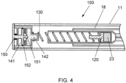
- Figure 4 shows the injection device 100 of the first embodiment in a final state.
- the temperature of the driving element 130 is raised above the threshold, such that the driving element 130 changes from the first configuration to the second configuration.
- the expanded coil shape of the second configuration has a greater length than the compressed coil shape of the first configuration and so the driving element 130 exerts an axial force of the piston 120 as it expands.
- the rubber stopper 23 of the syringe 18 is displaced by the piston 120 towards the distal end of the medicament chamber, which causes the medicament to be dispensed through the needle of the syringe 18.
- the first embodiment provides an improved driving element for an auto-injector device and, in addition, the mechanism of the dispense mechanism can aid with warming the medicament prior to injection.
- the exothermic chemical reaction may be an exothermic neutralisation reaction between an acid and a base, for example, between citric acid and sodium hydroxide.
- the heating mechanism comprises a single chemical fluid which is contained in a chamber.
- the location and form of the chamber is substantially as described with respect to the second chamber above.
- the piercing element comprises an activation surface which triggers an exothermic process in the chemical fluid when the chemical fluid makes contact with the activation surface.
- the dispense button is configured to push the piercing element with the activation surface into the second chamber through the frangible membrane, which causes the generation of heat from the exothermic process.
- the chemical contained in the chamber is a supersaturated solution of, for example, sodium acetate trihydrate.
- the activation surface triggers an exothermic crystallisation process in the supersaturated solution.
- This heating mechanism provides a rechargeable energy source which can generate heat through multiple phase changes, when the supersaturated solution is reformed under the influence of heat followed by gentle cooling.
- the dispense mechanism according to the embodiment can therefore be implemented as part of a reusable device.
- an injection device 200 according to a second embodiment is described. Elements of the embodiment which are not described are substantially the same as those of the first embodiment.
- the dispense mechanism 210 comprises a piston 220, a driving element 230 and a heating mechanism 240.
- the piston 220 is coupled to the rubber stopper 23 of the syringe 18, and the driving element 230 is disposed within the syringe 18 between the piston 220 and the proximal end of the medicament chamber.
- the driving element 230 is formed from a SMA, substantially as described with respect to the first embodiment.
- the SMA forms a driving element 230 having a first configuration, which is a compressed coil shape, and a second configuration, which is an expanded coil shape.
- the expanded coil shape of the second configuration has a greater length than the compressed coil shape of the first configuration.
- the shape of the driving element 230 changes from a compressed coil shape to an expanded coil shape and therefore the length of the driving element 230 increases.
- the expansion of the driving element 230 exerts an axial force on the piston 220, which displaces the rubber stopper 23 of the syringe 18 towards the distal end of the medicament chamber.
- the change in configuration of the driving element 230 therefore causes the medicament 16 to be dispensed through the needle 17 of the syringe 18.
- the heating mechanism 240 of the dispense mechanism 220 is configured to raise the temperature of the driving element 230 when the dispense mechanism 220 is activated.
- the heating mechanism 240 comprises a fluid reservoir, a heater and a pump disposed in an external device (not shown), and a connecting tube 241 arranged to connect the fluid reservoir with the proximal end of the medicament chamber.
- the temperature of the driving element 230 is raised when a heated fluid 243, or gas, enters the proximal end of the medicament chamber through the connecting tube 241.
- the driving element 230 is immersed in the heated fluid 243, which improves the rate at which the temperature of the driving element 230 is raised.
- the fluid 243 or, alternatively, the gas, for heating the driving element 230 is stored in the fluid reservoir and heated by the heater in the external device.
- the pump forces the heated fluid 243 through the connecting tube 241 into the proximal end of the medicament chamber.
- a return tube 242 allows the heated fluid 243 to flow back to the external device, whereby the circulation of the heated fluid 243 improves the rate at which the temperature of the driving element 230 is raised.
- Figure 6 shows the injection device 200 of the second embodiment in an activated state.
- the driving element 230 is immersed in the heated fluid 243, and the temperature of the driving element 230 is raised above the threshold, such that the driving element 230 changes from the first configuration to the second configuration.
- the expanded coil shape of the second configuration has a greater length than the compressed coil shape of the first configuration and so the driving element 230 exerts an axial force of the piston 220 as it expands.
- the rubber stopper 23 of the syringe 18 is displaced by the piston 220 towards the proximal end of the medicament chamber, which causes the medicament to be dispensed through the needle 17 of the syringe 18.
- Figure 5 and Figure 6 depict an injection device 200 comprising the syringe 18 and dispense mechanism 210 only, the dispense mechanism 210 of the second embodiment may be implemented as part of an injection device having a housing and any other parts described with respect to Figures 1 to 4 .
- the second embodiment can therefore provide an improved driving element for an auto-injector device and, in addition, the mechanism of the dispense mechanism can aid with warming the medicament prior to injection. By warming the medicament to be closer to the body temperature of the user, prior to injection, the comfort of the user can be improved.
- the chemicals of the first embodiment may be any suitable chemicals which can be combined to produce heat in an exothermic process, and may be in a solid, liquid or gas form.
- the first chemical may be powdered calcium oxide or quicklime and the second chemical is water, and the combination of the first and second chemicals generates heat from an exothermic chemical reaction forming a calcium hydroxide solution.
- the first chemical may be a dehydrated salt such as calcium chloride or copper (II) sulphate and the second chemical is water, wherein the heating mechanism is an exothermic rehydration process.
- the driving element of any embodiment may be formed as a coiled spring, as described, or may be formed as a flat folded spring, e.g. a concertina shape, which expands when the temperature of the driving element is raised above the threshold.
- drug or “medicament” are used synonymously herein and describe a pharmaceutical formulation containing one or more active pharmaceutical ingredients or pharmaceutically acceptable salts or solvates thereof, and optionally a pharmaceutically acceptable carrier.
- An active pharmaceutical ingredient (“API”), in the broadest terms, is a chemical structure that has a biological effect on humans or animals. In pharmacology, a drug or medicament is used in the treatment, cure, prevention, or diagnosis of disease or used to otherwise enhance physical or mental well-being. A drug or medicament may be used for a limited duration, or on a regular basis for chronic disorders.
- a drug or medicament can include at least one API, or combinations thereof, in various types of formulations, for the treatment of one or more diseases.
- API may include small molecules having a molecular weight of 500 Da or less; polypeptides, peptides and proteins (e.g., hormones, growth factors, antibodies, antibody fragments, and enzymes); carbohydrates and polysaccharides; and nucleic acids, double or single stranded DNA (including naked and cDNA), RNA, antisense nucleic acids such as antisense DNA and RNA, small interfering RNA (siRNA), ribozymes, genes, and oligonucleotides. Nucleic acids may be incorporated into molecular delivery systems such as vectors, plasmids, or liposomes. Mixtures of one or more drugs are also contemplated.
- a drug delivery device shall encompass any type of device or system configured to dispense a drug or medicament into a human or animal body.
- a drug delivery device may be an injection device (e.g., syringe, pen injector, auto injector, large-volume device, pump, perfusion system, or other device configured for intraocular, subcutaneous, intramuscular, or intravascular delivery), skin patch (e.g., osmotic, chemical, micro-needle), inhaler (e.g., nasal or pulmonary), an implantable device (e.g., drug- or API-coated stent, capsule), or a feeding system for the gastro-intestinal tract.
- the presently described drugs may be particularly useful with injection devices that include a needle, e.g., a hypodermic needle for example having a Gauge number of 24 or higher.
- the drug or medicament may be contained in a primary package or "drug container" adapted for use with a drug delivery device.
- the drug container may be, e.g., a cartridge, syringe, reservoir, or other solid or flexible vessel configured to provide a suitable chamber for storage (e.g., short-or long-term storage) of one or more drugs.
- the chamber may be designed to store a drug for at least one day (e.g., 1 to at least 30 days).
- the chamber may be designed to store a drug for about 1 month to about 2 years. Storage may occur at room temperature (e.g., about 20°C), or refrigerated temperatures (e.g., from about - 4°C to about 4°C).
- the drug container may be or may include a dual-chamber cartridge configured to store two or more components of the pharmaceutical formulation to-be-administered (e.g., an API and a diluent, or two different drugs) separately, one in each chamber.
- the two chambers of the dual-chamber cartridge may be configured to allow mixing between the two or more components prior to and/or during dispensing into the human or animal body.
- the two chambers may be configured such that they are in fluid communication with each other (e.g., by way of a conduit between the two chambers) and allow mixing of the two components when desired by a user prior to dispensing.
- the two chambers may be configured to allow mixing as the components are being dispensed into the human or animal body.
- the drugs or medicaments contained in the drug delivery devices as described herein can be used for the treatment and/or prophylaxis of many different types of medical disorders.
- disorders include, e.g., diabetes mellitus or complications associated with diabetes mellitus such as diabetic retinopathy, thromboembolism disorders such as deep vein or pulmonary thromboembolism.
- Further examples of disorders are acute coronary syndrome (ACS), angina, myocardial infarction, cancer, macular degeneration, inflammation, hay fever, atherosclerosis and/or rheumatoid arthritis.
- APIs and drugs are those as described in handbooks such as Rote Liste 2014, for example, without limitation, main groups 12 (antidiabetic drugs) or 86 (oncology drugs), and Merck Index, 15th edition.
- APIs for the treatment and/or prophylaxis of type 1 or type 2 diabetes mellitus or complications associated with type 1 or type 2 diabetes mellitus include an insulin, e.g., human insulin, or a human insulin analogue or derivative, a glucagon-like peptide (GLP-1), GLP-1 analogues or GLP-1 receptor agonists, or an analogue or derivative thereof, a dipeptidyl peptidase-4 (DPP4) inhibitor, or a pharmaceutically acceptable salt or solvate thereof, or any mixture thereof.
- GLP-1 glucagon-like peptide
- DPP4 dipeptidyl peptidase-4
- the terms “analogue” and “derivative” refer to any substance which is sufficiently structurally similar to the original substance so as to have substantially similar functionality or activity (e.g., therapeutic effectiveness).
- analogue refers to a polypeptide which has a molecular structure which formally can be derived from the structure of a naturally occurring peptide, for example that of human insulin, by deleting and/or exchanging at least one amino acid residue occurring in the naturally occurring peptide and/or by adding at least one amino acid residue.
- the added and/or exchanged amino acid residue can either be codable amino acid residues or other naturally occurring residues or purely synthetic amino acid residues.
- Insulin analogues are also referred to as "insulin receptor ligands".
- the term "derivative” refers to a polypeptide which has a molecular structure which formally can be derived from the structure of a naturally occurring peptide, for example that of human insulin, in which one or more organic substituent (e.g. a fatty acid) is bound to one or more of the amino acids.
- one or more amino acids occurring in the naturally occurring peptide may have been deleted and/or replaced by other amino acids, including non-codeable amino acids, or amino acids, including non-codeable, have been added to the naturally occurring peptide.
- insulin analogues examples include Gly(A21), Arg(B31), Arg(B32) human insulin (insulin glargine); Lys(B3), Glu(B29) human insulin (insulin glulisine); Lys(B28), Pro(B29) human insulin (insulin lispro); Asp(B28) human insulin (insulin aspart); human insulin, wherein proline in position B28 is replaced by Asp, Lys, Leu, Val or Ala and wherein in position B29 Lys may be replaced by Pro; Ala(B26) human insulin; Des(B28-B30) human insulin; Des(B27) human insulin and Des(B30) human insulin.
- insulin derivatives are, for example, B29-N-myristoyl-des(B30) human insulin, Lys(B29) (N- tetradecanoyl)-des(B30) human insulin (insulin detemir, Levemir ® ); B29-N-palmitoyl-des(B30) human insulin; B29-N-myristoyl human insulin; B29-N-palmitoyl human insulin; B28-N-myristoyl LysB28ProB29 human insulin; B28-N-palmitoyl-LysB28ProB29 human insulin; B30-N-myristoyl-ThrB29LysB30 human insulin; B30-N-palmitoyl- ThrB29LysB30 human insulin; B29-N-(N-palmitoyl-gamma-glutamyl)-des(B30) human insulin, B29-N-omega-carboxypentadecanoyl-gamma-g
- GLP-1, GLP-1 analogues and GLP-1 receptor agonists are, for example, Lixisenatide ( Lyxumia ® , Exenatide (Exendin-4, Byetta ® , Bydureon ® , a 39 amino acid peptide which is produced by the salivary glands of the Gila monster), Liraglutide (Victoza ® ), Semaglutide, Taspoglutide, Albiglutide (Syncria ® ), Dulaglutide (Trulicity ® ), rExendin-4, CJC-1134-PC, PB-1023, TTP-054, Langlenatide/ HM-11260C, CM-3, GLP-1 Eligen, ORMD-0901, NN-9924, NN-9926, NN-9927, Nodexen, Viador-GLP-1, CVX-096, ZYOG-1, ZYD-1, GSK-2374697, DA-3091, MAR-701, MAR709
- oligonucleotide is, for example: mipomersen sodium (Kynamro ® ), a cholesterol-reducing antisense therapeutic for the treatment of familial hypercholesterolemia.
- DPP4 inhibitors are Vildagliptin, Sitagliptin, Denagliptin, Saxagliptin, Berberine.
- hormones include hypophysis hormones or hypothalamus hormones or regulatory active peptides and their antagonists, such as Gonadotropine (Follitropin, Lutropin, Choriongonadotropin, Menotropin), Somatropine (Somatropin), Desmopressin, Terlipressin, Gonadorelin, Triptorelin, Leuprorelin, Buserelin, Nafarelin, and Goserelin.
- Gonadotropine Follitropin, Lutropin, Choriongonadotropin, Menotropin
- Somatropine Somatropin
- Desmopressin Terlipressin
- Gonadorelin Triptorelin
- Leuprorelin Buserelin
- Nafarelin Nafarelin
- Goserelin Goserelin.
- polysaccharides include a glucosaminoglycane, a hyaluronic acid, a heparin, a low molecular weight heparin or an ultra-low molecular weight heparin or a derivative thereof, or a sulphated polysaccharide, e.g. a poly-sulphated form of the above-mentioned polysaccharides, and/or a pharmaceutically acceptable salt thereof.
- a pharmaceutically acceptable salt of a poly-sulphated low molecular weight heparin is enoxaparin sodium.
- An example of a hyaluronic acid derivative is Hylan G-F 20 (Synvisc ® ), a sodium hyaluronate.
- antibody refers to an immunoglobulin molecule or an antigen-binding portion thereof.
- antigen-binding portions of immunoglobulin molecules include F(ab) and F(ab')2 fragments, which retain the ability to bind antigens.
- the antibody can be polyclonal, monoclonal, recombinant, chimeric, de-immunized or humanized, fully human, non-human, (e.g., murine), or single chain antibody.
- the antibody has effector function and can fix a complement.
- the antibody has reduced or no ability to bind an Fc receptor.
- the antibody can be an isotype or subtype, an antibody fragment or mutant, which does not support binding to an Fc receptor, e.g., it has a mutagenized or deleted Fc receptor binding region.
- the term antibody also includes an antigen-binding molecule based on tetravalent bispecific tandem immunoglobulins (TBTI) and/or a dual variable region antibody-like binding protein having cross-over binding region orientation (CODV).
- TBTI tetravalent bispecific tandem immunoglobulins
- CODV cross-over binding region orientation
- fragment refers to a polypeptide derived from an antibody polypeptide molecule (e.g., an antibody heavy and/or light chain polypeptide) that does not comprise a full-length antibody polypeptide, but that still comprises at least a portion of a full-length antibody polypeptide that is capable of binding to an antigen.
- Antibody fragments can comprise a cleaved portion of a full length antibody polypeptide, although the term is not limited to such cleaved fragments.
- Antibody fragments that are useful in the present invention include, for example, Fab fragments, F(ab')2 fragments, scFv (single-chain Fv) fragments, linear antibodies, monospecific or multispecific antibody fragments such as bispecific, trispecific, tetraspecific and multispecific antibodies (e.g., diabodies, triabodies, tetrabodies), monovalent or multivalent antibody fragments such as bivalent, trivalent, tetravalent and multivalent antibodies, minibodies, chelating recombinant antibodies, tribodies or bibodies, intrabodies, nanobodies, small modular immunopharmaceuticals (SMIP), binding-domain immunoglobulin fusion proteins, camelized antibodies, and VHH containing antibodies. Additional examples of antigen-binding antibody fragments are known in the art.
- SMIP small modular immunopharmaceuticals
- CDR complementarity-determining region
- framework region refers to amino acid sequences within the variable region of both heavy and light chain polypeptides that are not CDR sequences, and are primarily responsible for maintaining correct positioning of the CDR sequences to permit antigen binding.
- framework regions themselves typically do not directly participate in antigen binding, as is known in the art, certain residues within the framework regions of certain antibodies can directly participate in antigen binding or can affect the ability of one or more amino acids in CDRs to interact with antigen.
- antibodies are anti PCSK-9 mAb (e.g., Alirocumab), anti IL-6 mAb (e.g., Sarilumab), and anti IL-4 mAb (e.g., Dupilumab).
- PCSK-9 mAb e.g., Alirocumab
- anti IL-6 mAb e.g., Sarilumab
- anti IL-4 mAb e.g., Dupilumab
- Pharmaceutically acceptable salts of any API described herein are also contemplated for use in a drug or medicament in a drug delivery device.
- Pharmaceutically acceptable salts are for example acid addition salts and basic salts.
Claims (13)
- Dispositif auto-injecteur (100) comprenant :un réservoir de médicament (18) ;un bouchon (23) pour expulser un médicament du réservoir de médicament ;un élément d'entraînement (130), formé à partir d'un alliage à mémoire de forme, qui a une première configuration et une seconde configuration et qui est configuré pour changer de forme de la première configuration à la seconde configuration lorsque la température de l'élément d'entraînement est élevée au-dessus d'une température de changement de forme, de manière à entraîner le bouchon du mécanisme de seringue à travers le réservoir de médicament ; etun mécanisme de chauffage (140) configuré pour chauffer activement l'élément d'entraînement, caractérisé en ce que :
le mécanisme de chauffage est un élément de chauffage chimique configuré pour générer de la chaleur par un processus exothermique. - Dispositif auto-injecteur selon la revendication 1, la première configuration de l'élément d'entraînement étant une forme de bobine comprimée, et la seconde configuration de l'élément d'entraînement étant une forme de bobine dilatée.
- Dispositif auto-injecteur selon la revendication 1 ou la revendication 2, le processus exothermique étant une cristallisation exothermique d'une solution sursaturée.
- Dispositif auto-injecteur selon l'une quelconque des revendications précédentes, le processus exothermique étant une réhydratation exothermique d'un sel déshydraté.
- Dispositif auto-injecteur selon l'une quelconque des revendications précédentes, le processus exothermique étant une réaction chimique exothermique entre un premier produit chimique et un second produit chimique.
- Dispositif auto-injecteur selon la revendication 5, l'élément de chauffage chimique comprenant :une première chambre (141) contenant le premier produit chimique,une seconde chambre (142) contenant le second produit chimique, etune membrane frangible (143) agencée pour séparer le premier produit chimique du second produit chimique.
- Dispositif auto-injecteur selon l'une quelconque des revendications précédentes, l'alliage à mémoire de forme étant un alliage nickel-titane.
- Dispositif auto-injecteur selon l'une quelconque des revendications précédentes, comprenant en outre un médicament (16) qui est retenu dans le réservoir de médicament et qui est agencé pour être expulsé du réservoir de médicament par le bouchon.
- Dispositif auto-injecteur (100) comprenant :un réservoir de médicament (18) ;un bouchon (23) pour expulser un médicament du réservoir de médicament ;un élément d'entraînement (130), formé à partir d'un alliage à mémoire de forme, qui a une première configuration et une seconde configuration et qui est configuré pour changer de forme de la première configuration à la seconde configuration lorsque la température de l'élément d'entraînement est élevée au-dessus d'une température de changement de forme, de manière à entraîner le bouchon du mécanisme de seringue à travers le réservoir de médicament ; etun mécanisme de chauffage (140) configuré pour chauffer activement l'élément d'entraînement, caractérisé en ce que :
le mécanisme de chauffage comprend :un réservoir de fluide pour retenir un fluide ;un dispositif de chauffage configuré pour chauffer le fluide dans le réservoir de fluide ;une pompe configurée pour expulser le fluide du réservoir de fluide ; etun conduit de raccordement (241) agencé pour transporter le fluide du réservoir de fluide vers l'élément d'entraînement. - Dispositif auto-injecteur selon la revendication 9, la première configuration de l'élément d'entraînement étant une forme de bobine comprimée, et la seconde configuration de l'élément d'entraînement étant une forme de bobine dilatée.
- Dispositif auto-injecteur selon la revendication 9 ou la revendication 10, l'élément d'entraînement étant disposé dans une extrémité proximale du réservoir de médicament, et le tube de raccordement étant configuré pour remplir l'extrémité proximale du réservoir de médicament avec le fluide.
- Dispositif auto-injecteur selon l'une quelconque des revendications 9 à 11, l'alliage à mémoire de forme étant un alliage nickel-titane.
- Dispositif auto-injecteur selon l'une quelconque des revendications 9 à 12, comprenant en outre un médicament (16) qui est retenu dans le réservoir de médicament et qui est agencé pour être expulsé du réservoir de médicament par le bouchon.
Applications Claiming Priority (2)
| Application Number | Priority Date | Filing Date | Title |
|---|---|---|---|
| EP15196668 | 2015-11-27 | ||
| PCT/EP2016/078243 WO2017089255A1 (fr) | 2015-11-27 | 2016-11-21 | Dispositif auto-injecteur |
Publications (3)
| Publication Number | Publication Date |
|---|---|
| EP3380142A1 EP3380142A1 (fr) | 2018-10-03 |
| EP3380142B1 true EP3380142B1 (fr) | 2023-11-15 |
| EP3380142C0 EP3380142C0 (fr) | 2023-11-15 |
Family
ID=54705474
Family Applications (1)
| Application Number | Title | Priority Date | Filing Date |
|---|---|---|---|
| EP16798722.1A Active EP3380142B1 (fr) | 2015-11-27 | 2016-11-21 | Dispositif injecteur automatique |
Country Status (5)
| Country | Link |
|---|---|
| US (2) | US11058819B2 (fr) |
| EP (1) | EP3380142B1 (fr) |
| JP (1) | JP6997086B2 (fr) |
| CN (1) | CN108601896B (fr) |
| WO (1) | WO2017089255A1 (fr) |
Families Citing this family (3)
| Publication number | Priority date | Publication date | Assignee | Title |
|---|---|---|---|---|
| USD926975S1 (en) * | 2018-09-27 | 2021-08-03 | Phc Holdings Corporation | Cartridge for medicine injector |
| US11311670B2 (en) * | 2018-10-12 | 2022-04-26 | Flex Ltd | Automatic injection device having a passive drive system with a shape memory spring |
| US20220395639A1 (en) | 2019-07-01 | 2022-12-15 | Sanofi | Chemical wake-up mechanism for active electronics in pen injectors |
Family Cites Families (19)
| Publication number | Priority date | Publication date | Assignee | Title |
|---|---|---|---|---|
| US4518384A (en) * | 1983-06-17 | 1985-05-21 | Survival Technology, Inc. | Multiple medicament cartridge clip and medicament discharging device therefor |
| JPS62121877A (ja) * | 1985-11-22 | 1987-06-03 | Matsushita Electric Works Ltd | 熱駆動ポンプ |
| EP0387375B1 (fr) * | 1989-03-15 | 1994-02-23 | Mitsubishi Materials Corporation | Injecteur de colmatage |
| JPH04105660A (ja) * | 1990-08-27 | 1992-04-07 | Olympus Optical Co Ltd | 生体管路拡張具 |
| JPH04200565A (ja) * | 1990-11-30 | 1992-07-21 | Olympus Optical Co Ltd | 医療具 |
| JPH05168680A (ja) * | 1991-12-03 | 1993-07-02 | Olympus Optical Co Ltd | 医療用カプセル装置 |
| JPH05212093A (ja) | 1992-02-07 | 1993-08-24 | Olympus Optical Co Ltd | 自動走行カプセル装置 |
| US6375638B2 (en) * | 1999-02-12 | 2002-04-23 | Medtronic Minimed, Inc. | Incremental motion pump mechanisms powered by shape memory alloy wire or the like |
| CA2396569C (fr) * | 2000-01-07 | 2010-03-23 | Biovalve Technologies, Inc. | Dispositif d'injection |
| TWI314464B (en) * | 2002-06-24 | 2009-09-11 | Alza Corp | Reusable, spring driven autoinjector |
| ATE510174T1 (de) * | 2003-05-21 | 2011-06-15 | Alexza Pharmaceuticals Inc | Schlag gezündete unabhängige heizeinheit |
| JP5148274B2 (ja) | 2005-05-27 | 2013-02-20 | オリンパス株式会社 | 被検体内導入装置 |
| CN101528285B (zh) * | 2006-10-26 | 2012-10-31 | 马林克罗特有限公司 | 具有热-机械驱动器的医用流体注射器 |
| US8388571B2 (en) * | 2009-10-06 | 2013-03-05 | Bioquiddity, Inc. | Fluid dispenser with non-electric fluid heating component |
| US8840601B2 (en) * | 2010-03-24 | 2014-09-23 | Shifamed Holdings, Llc | Intravascular tissue disruption |
| CN111617347B (zh) | 2013-03-15 | 2023-09-29 | 安进公司 | 身体轮廓可调适的自动注射器装置 |
| CN103316398A (zh) * | 2013-07-02 | 2013-09-25 | 浙江大学 | 基于形状记忆合金驱动的针筒微量注射式输液装置及其方法 |
| US20150045763A1 (en) * | 2013-08-06 | 2015-02-12 | Fresenius Medical Care Holdings, Inc. | Self-warming peritoneal dialysis solution bag |
| GB2541719B (en) * | 2015-08-27 | 2019-06-12 | Nerudia Ltd | An inhaler |
-
2016
- 2016-11-21 WO PCT/EP2016/078243 patent/WO2017089255A1/fr active Application Filing
- 2016-11-21 US US15/779,068 patent/US11058819B2/en active Active
- 2016-11-21 JP JP2018527162A patent/JP6997086B2/ja active Active
- 2016-11-21 CN CN201680079984.4A patent/CN108601896B/zh active Active
- 2016-11-21 EP EP16798722.1A patent/EP3380142B1/fr active Active
-
2020
- 2020-11-16 US US17/099,707 patent/US11752264B2/en active Active
Also Published As
| Publication number | Publication date |
|---|---|
| CN108601896B (zh) | 2024-01-19 |
| US11752264B2 (en) | 2023-09-12 |
| US20190134309A1 (en) | 2019-05-09 |
| US11058819B2 (en) | 2021-07-13 |
| JP6997086B2 (ja) | 2022-01-17 |
| JP2019500093A (ja) | 2019-01-10 |
| WO2017089255A1 (fr) | 2017-06-01 |
| EP3380142C0 (fr) | 2023-11-15 |
| US20210077724A1 (en) | 2021-03-18 |
| EP3380142A1 (fr) | 2018-10-03 |
| CN108601896A (zh) | 2018-09-28 |
Similar Documents
| Publication | Publication Date | Title |
|---|---|---|
| US10842947B2 (en) | Medicament injection device | |
| US11071832B2 (en) | Medicament injection device | |
| EP3380139B1 (fr) | Dispositifs d'administration de médicaments | |
| EP3380165B1 (fr) | Dispositif d'injection de médicament avec protecteur de l'aiguille assisté par des ressorts | |
| US11752264B2 (en) | Auto-injector device | |
| US11419992B2 (en) | Medicament injection device | |
| EP3380159B1 (fr) | Dispositif d'injection | |
| EP3380172B1 (fr) | Capuchon de dispositif d'injection et dispositif d'injection | |
| EP3380136B1 (fr) | Auto-injecteur | |
| US20240091450A1 (en) | Injector Device |
Legal Events
| Date | Code | Title | Description |
|---|---|---|---|
| STAA | Information on the status of an ep patent application or granted ep patent |
Free format text: STATUS: UNKNOWN |
|
| STAA | Information on the status of an ep patent application or granted ep patent |
Free format text: STATUS: THE INTERNATIONAL PUBLICATION HAS BEEN MADE |
|
| PUAI | Public reference made under article 153(3) epc to a published international application that has entered the european phase |
Free format text: ORIGINAL CODE: 0009012 |
|
| STAA | Information on the status of an ep patent application or granted ep patent |
Free format text: STATUS: REQUEST FOR EXAMINATION WAS MADE |
|
| 17P | Request for examination filed |
Effective date: 20180627 |
|
| AK | Designated contracting states |
Kind code of ref document: A1 Designated state(s): AL AT BE BG CH CY CZ DE DK EE ES FI FR GB GR HR HU IE IS IT LI LT LU LV MC MK MT NL NO PL PT RO RS SE SI SK SM TR |
|
| AX | Request for extension of the european patent |
Extension state: BA ME |
|
| DAV | Request for validation of the european patent (deleted) | ||
| DAX | Request for extension of the european patent (deleted) | ||
| REG | Reference to a national code |
Ref country code: HK Ref legal event code: DE Ref document number: 1261550 Country of ref document: HK |
|
| GRAP | Despatch of communication of intention to grant a patent |
Free format text: ORIGINAL CODE: EPIDOSNIGR1 |
|
| STAA | Information on the status of an ep patent application or granted ep patent |
Free format text: STATUS: GRANT OF PATENT IS INTENDED |
|
| INTG | Intention to grant announced |
Effective date: 20230428 |
|
| GRAS | Grant fee paid |
Free format text: ORIGINAL CODE: EPIDOSNIGR3 |
|
| GRAA | (expected) grant |
Free format text: ORIGINAL CODE: 0009210 |
|
| STAA | Information on the status of an ep patent application or granted ep patent |
Free format text: STATUS: THE PATENT HAS BEEN GRANTED |
|
| AK | Designated contracting states |
Kind code of ref document: B1 Designated state(s): AL AT BE BG CH CY CZ DE DK EE ES FI FR GB GR HR HU IE IS IT LI LT LU LV MC MK MT NL NO PL PT RO RS SE SI SK SM TR |
|
| REG | Reference to a national code |
Ref country code: CH Ref legal event code: EP Ref country code: GB Ref legal event code: FG4D |
|
| REG | Reference to a national code |
Ref country code: DE Ref legal event code: R096 Ref document number: 602016084157 Country of ref document: DE |
|
| REG | Reference to a national code |
Ref country code: IE Ref legal event code: FG4D |
|
| U01 | Request for unitary effect filed |
Effective date: 20231115 |
|
| U07 | Unitary effect registered |
Designated state(s): AT BE BG DE DK EE FI FR IT LT LU LV MT NL PT SE SI Effective date: 20231120 |
|
| U20 | Renewal fee paid [unitary effect] |
Year of fee payment: 8 Effective date: 20231129 |
|
| PGFP | Annual fee paid to national office [announced via postgrant information from national office to epo] |
Ref country code: GB Payment date: 20231124 Year of fee payment: 8 |
|
| PGFP | Annual fee paid to national office [announced via postgrant information from national office to epo] |
Ref country code: CH Payment date: 20231201 Year of fee payment: 8 |
|
| PG25 | Lapsed in a contracting state [announced via postgrant information from national office to epo] |
Ref country code: GR Free format text: LAPSE BECAUSE OF FAILURE TO SUBMIT A TRANSLATION OF THE DESCRIPTION OR TO PAY THE FEE WITHIN THE PRESCRIBED TIME-LIMIT Effective date: 20240216 |
|
| PG25 | Lapsed in a contracting state [announced via postgrant information from national office to epo] |
Ref country code: IS Free format text: LAPSE BECAUSE OF FAILURE TO SUBMIT A TRANSLATION OF THE DESCRIPTION OR TO PAY THE FEE WITHIN THE PRESCRIBED TIME-LIMIT Effective date: 20240315 |