EP3379763B1 - Method for scheduling distributed virtual resource blocks - Google Patents
Method for scheduling distributed virtual resource blocks Download PDFInfo
- Publication number
- EP3379763B1 EP3379763B1 EP18171916.2A EP18171916A EP3379763B1 EP 3379763 B1 EP3379763 B1 EP 3379763B1 EP 18171916 A EP18171916 A EP 18171916A EP 3379763 B1 EP3379763 B1 EP 3379763B1
- Authority
- EP
- European Patent Office
- Prior art keywords
- dvrb
- prbs
- indexes
- rbg
- prb
- Prior art date
- Legal status (The legal status is an assumption and is not a legal conclusion. Google has not performed a legal analysis and makes no representation as to the accuracy of the status listed.)
- Active
Links
Images


Classifications
-
- H—ELECTRICITY
- H04—ELECTRIC COMMUNICATION TECHNIQUE
- H04L—TRANSMISSION OF DIGITAL INFORMATION, e.g. TELEGRAPHIC COMMUNICATION
- H04L5/00—Arrangements affording multiple use of the transmission path
- H04L5/003—Arrangements for allocating sub-channels of the transmission path
- H04L5/0044—Allocation of payload; Allocation of data channels, e.g. PDSCH or PUSCH
-
- H—ELECTRICITY
- H04—ELECTRIC COMMUNICATION TECHNIQUE
- H04L—TRANSMISSION OF DIGITAL INFORMATION, e.g. TELEGRAPHIC COMMUNICATION
- H04L27/00—Modulated-carrier systems
- H04L27/26—Systems using multi-frequency codes
-
- H—ELECTRICITY
- H04—ELECTRIC COMMUNICATION TECHNIQUE
- H04L—TRANSMISSION OF DIGITAL INFORMATION, e.g. TELEGRAPHIC COMMUNICATION
- H04L1/00—Arrangements for detecting or preventing errors in the information received
- H04L1/004—Arrangements for detecting or preventing errors in the information received by using forward error control
- H04L1/0056—Systems characterized by the type of code used
- H04L1/0071—Use of interleaving
-
- H—ELECTRICITY
- H04—ELECTRIC COMMUNICATION TECHNIQUE
- H04L—TRANSMISSION OF DIGITAL INFORMATION, e.g. TELEGRAPHIC COMMUNICATION
- H04L1/00—Arrangements for detecting or preventing errors in the information received
- H04L1/02—Arrangements for detecting or preventing errors in the information received by diversity reception
- H04L1/04—Arrangements for detecting or preventing errors in the information received by diversity reception using frequency diversity
-
- H—ELECTRICITY
- H04—ELECTRIC COMMUNICATION TECHNIQUE
- H04L—TRANSMISSION OF DIGITAL INFORMATION, e.g. TELEGRAPHIC COMMUNICATION
- H04L5/00—Arrangements affording multiple use of the transmission path
- H04L5/0001—Arrangements for dividing the transmission path
- H04L5/0003—Two-dimensional division
- H04L5/0005—Time-frequency
- H04L5/0007—Time-frequency the frequencies being orthogonal, e.g. OFDM(A) or DMT
-
- H—ELECTRICITY
- H04—ELECTRIC COMMUNICATION TECHNIQUE
- H04L—TRANSMISSION OF DIGITAL INFORMATION, e.g. TELEGRAPHIC COMMUNICATION
- H04L5/00—Arrangements affording multiple use of the transmission path
- H04L5/0001—Arrangements for dividing the transmission path
- H04L5/0028—Variable division
-
- H—ELECTRICITY
- H04—ELECTRIC COMMUNICATION TECHNIQUE
- H04L—TRANSMISSION OF DIGITAL INFORMATION, e.g. TELEGRAPHIC COMMUNICATION
- H04L5/00—Arrangements affording multiple use of the transmission path
- H04L5/003—Arrangements for allocating sub-channels of the transmission path
- H04L5/0037—Inter-user or inter-terminal allocation
- H04L5/0039—Frequency-contiguous, i.e. with no allocation of frequencies for one user or terminal between the frequencies allocated to another
-
- H—ELECTRICITY
- H04—ELECTRIC COMMUNICATION TECHNIQUE
- H04L—TRANSMISSION OF DIGITAL INFORMATION, e.g. TELEGRAPHIC COMMUNICATION
- H04L5/00—Arrangements affording multiple use of the transmission path
- H04L5/003—Arrangements for allocating sub-channels of the transmission path
- H04L5/0037—Inter-user or inter-terminal allocation
- H04L5/0041—Frequency-non-contiguous
-
- H—ELECTRICITY
- H04—ELECTRIC COMMUNICATION TECHNIQUE
- H04L—TRANSMISSION OF DIGITAL INFORMATION, e.g. TELEGRAPHIC COMMUNICATION
- H04L5/00—Arrangements affording multiple use of the transmission path
- H04L5/0091—Signalling for the administration of the divided path, e.g. signalling of configuration information
- H04L5/0092—Indication of how the channel is divided
-
- H—ELECTRICITY
- H04—ELECTRIC COMMUNICATION TECHNIQUE
- H04W—WIRELESS COMMUNICATION NETWORKS
- H04W72/00—Local resource management
- H04W72/04—Wireless resource allocation
-
- H—ELECTRICITY
- H04—ELECTRIC COMMUNICATION TECHNIQUE
- H04L—TRANSMISSION OF DIGITAL INFORMATION, e.g. TELEGRAPHIC COMMUNICATION
- H04L5/00—Arrangements affording multiple use of the transmission path
- H04L5/003—Arrangements for allocating sub-channels of the transmission path
- H04L5/0058—Allocation criteria
- H04L5/006—Quality of the received signal, e.g. BER, SNR, water filling
-
- H—ELECTRICITY
- H04—ELECTRIC COMMUNICATION TECHNIQUE
- H04L—TRANSMISSION OF DIGITAL INFORMATION, e.g. TELEGRAPHIC COMMUNICATION
- H04L5/00—Arrangements affording multiple use of the transmission path
- H04L5/003—Arrangements for allocating sub-channels of the transmission path
- H04L5/0058—Allocation criteria
- H04L5/0064—Rate requirement of the data, e.g. scalable bandwidth, data priority
-
- H—ELECTRICITY
- H04—ELECTRIC COMMUNICATION TECHNIQUE
- H04L—TRANSMISSION OF DIGITAL INFORMATION, e.g. TELEGRAPHIC COMMUNICATION
- H04L5/00—Arrangements affording multiple use of the transmission path
- H04L5/003—Arrangements for allocating sub-channels of the transmission path
- H04L5/0078—Timing of allocation
- H04L5/0085—Timing of allocation when channel conditions change
-
- H—ELECTRICITY
- H04—ELECTRIC COMMUNICATION TECHNIQUE
- H04W—WIRELESS COMMUNICATION NETWORKS
- H04W72/00—Local resource management
-
- H—ELECTRICITY
- H04—ELECTRIC COMMUNICATION TECHNIQUE
- H04W—WIRELESS COMMUNICATION NETWORKS
- H04W72/00—Local resource management
- H04W72/20—Control channels or signalling for resource management
- H04W72/23—Control channels or signalling for resource management in the downlink direction of a wireless link, i.e. towards a terminal
Definitions
- the present invention relates to a broadband wireless mobile communication system, and more particularly, to radio resource scheduling for uplink/downlink packet data transmission in a cellular OFDM wireless packet communication system.
- uplink/downlink data packet transmission is made on a subframe basis and one subframe is defined by a certain time interval including a plurality of OFDM symbols.
- OFDM orthogonal frequency division multiplex
- the Third Generation Partnership Project (3GPP) supports a type 1 radio frame structure applicable to frequency division duplex (FDD), and a type 2 radio frame structure applicable to time division duplex (TDD).
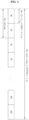
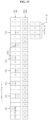
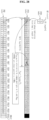
- the structure of a type 1 radio frame is shown in FIG. 1 .
- the type 1 radio frame includes ten subframes, each of which consists of two slots.
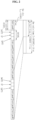
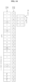
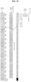
- the structure of a type 2 radio frame is shown in FIG. 2 .
- the type 2 radio frame includes two half-frames, each of which is made up of five subframes, a downlink piloting time slot (DwPTS), a gap period (GP), and an uplink piloting time slot (UpPTS), in which one subframe consists of two slots. That is, one subframe is composed of two slots irrespective of the radio frame type.
- DwPTS downlink piloting time slot
- GP gap period
- UpPTS uplink piloting time slot
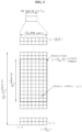
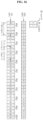
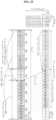
- a signal transmitted in each slot can be described by a resource grid including N RB DL N SC RB subcarriers and N symb DL OFDM symbols.
- N RB DL represents the number of resource blocks (RBs) in a downlink
- N SC RB represents the number of subcarriers constituting one RB
- N symb DL represents the number of OFDM symbols in one downlink slot.
- the structure of this resource grid is shown in FIG. 3 .
- RBs are used to describe a mapping relationship between certain physical channels and resource elements.
- the RBs can be classified into physical resource blocks (PRBs) and virtual resource blocks (VRBs), which means that a RB may be either one of a PRB or a VRB.
- PRBs physical resource blocks
- VRBs virtual resource blocks
- a mapping relationship between the VRBs and the PRBs can be described on a subframe basis. In more detail, it can be described in units of each of slots constituting one subframe. Also, the mapping relationship between the VRBs and the PRBs can be described using a mapping relationship between indexes of the VRBs and indexes of PRBs. A detailed description of this will be further given in embodiments of the present invention.
- a PRB is defined by N symb DL consecutive OFDM symbols in a time domain and N SC RB consecutive subcarriers in a frequency domain.
- One PRB is therefore composed of N symb DL N SC RB resource elements.
- the PRBs are assigned numbers from 0 to N RB DL ⁇ 1 in the frequency domain.
- a VRB can have the same size as that of the PRB.
- a pair of VRBs have a single VRB index in common (may hereinafter be referred to as a ⁇ VRB number') and are allocated over two slots of one subframe.
- N RB DL VRBs belonging to a first one of two slots constituting one subframe are each assigned any one index of 0 to N RB DL ⁇ 1
- N RB DL VRBs belonging to a second one of the two slots are likewise each assigned any one index of 0 to N RB DL ⁇ 1 .
- VRBs Some of the plurality of aforementioned VRBs are allocated as the localized type and the others are allocated as the distributed type.
- the VRBs allocated as the localized type will be referred to as 'localized virtual resource blocks (LVRBs)' and the VRBs allocated as the distributed type will be referred to as 'distributed virtual resource blocks (DVRBs)'.
- LVRBs 'localized virtual resource blocks
- DVRBs distributed virtual resource blocks
- the distributed VRBs may not be directly mapped to PRBs. That is, the indexes of the DVRBs can be mapped to the PRBs after being subjected to a series of processes.
- the order of a sequence of consecutive indexes of the DVRBs can be interleaved by a block interleaver.
- the sequence of consecutive indexes means that the index number is sequentially incremented by one beginning with 0.
- a sequence of indexes outputted from the interleaver is sequentially mapped to a sequence of consecutive indexes of PRB1s (see FIG. 6 ). It is assumed that the VRBs of FIG. 6 are all allocated as DVRBs.
- the sequence of indexes outputted from the interleaver is cyclically shifted by a predetermined number and the cyclically shifted index sequence is sequentially mapped to a sequence of consecutive indexes of PRB2s (see FIG. 7 ). It is assumed that the VRBs of FIG. 7 are all allocated as DVRBs. In this manner, PRB indexes and DVRB indexes can be mapped over two slots.
- a sequence of consecutive indexes of the DVRBs may be sequentially mapped to the sequence of consecutive indexes of the PRB1s without passing through the interleaver. Also, the sequence of consecutive indexes of the DVRBs may be cyclically shifted by the predetermined number without passing through the interleaver and the cyclically shifted index sequence may be sequentially mapped to the sequence of consecutive indexes of the PRB2s.
- a PRB1(i) and a PRB2(i) having the same index i can be mapped to a DVRB1(m) and a DVRB2(n) having different indexes m and n.
- a PRB1(1) and a PRB2(1) are mapped to a DVRB1(6) and a DVRB2(9) having different indexes.
- a frequency diversity effect can be obtained based on the DVRB mapping scheme.
- radio resources can be allocated to each terminal with a LVRB and/or DVRB scheme.
- the information indicating which scheme is used can be transmitted with a bitmap format.
- the allocation of radio resources to each terminal can be carried out in units of one RB.
- resources can be allocated with a granularity of '1' RB, but a large amount of bit overhead is required to transmit the allocation information with the bitmap format.
- LVRBs can be mapped to PRBs on an RBG basis.
- PRBs having three consecutive indexes a PRB1(i), PRB1(i+1), PRB1(i+2), PRB2(i), PRB2(i+1) and PRB2(i+2), may constitute one RBG, and LVRBs may be mapped to this RBG in units of an RBG.
- PRB1(i), PRB1(i+1), PRB1(i+2), PRB2(i), PRB2(i+1) and PRB2(i+2) were previously mapped by DVRBs, this RBG cannot be mapped by LVRBs on an RBG basis. That is, the DVRB mapping rules may restrict the RBG-unit LVRB mapping.
- the DVRB mapping rules may affect the LVRB mapping, there is a need to determine the DVRB mapping rules in consideration of the LVRB mapping.
- the document WO2009/088911 discloses an apparatus for communication using a wireless communication network including an interleaver and a transceiver.
- An object of the present invention devised to solve the problem lies on a resource scheduling method for efficiently combining scheduling of an FSS scheme and scheduling of an FDS scheme.
- index(PRB1(i)) represents an index of a PRB of an ith frequency band of the first slot
- index(PRB2(j)) represents an index of a PRB of a jth frequency band of the second slot
- a relationship of index(PRB1(k)) index(PRB2(k)) is established, as stated previously.
- index(VRB1(i)) represents an index of a VRB of an ith virtual frequency band of the first slot
- index(VRB2(j)) represents an index of a VRB of a jth virtual frequency band of the second slot
- a relationship of index(VRB1(k)) index(VRB2(k)) is established.
- VRBIs are mapped to PRB1s
- VRB2s are mapped to PRB2s.
- VRBs are classified into DVRBs and LVRBs.
- mapping LVRB1s to PRB1s and the rules for mapping LVRB2s to PRB2s are the same. However, the rules for mapping DVRB1s to PRB1s and the rules for mapping DVRB2s to PRB2s are different. That is, DVRBs are 'divided' and mapped to PRBs.
- one RB is defined in units of one slot.
- one RB is defined in units of one subframe, and this RB is divided into N D sub-RBs on a time axis, so that the DVRB mapping rules are generalized and described.
- N D 2
- a PRB defined in units of one subframe is divided into a first sub-PRB and a second sub-PRB
- a VRB defined in units of one subframe is divided into a first sub-VRB and a second sub-VRB.
- the first sub-PRB corresponds to the aforementioned PRB1
- the second sub-PRB corresponds to the aforementioned PRB2.
- the first sub-VRB corresponds to the aforementioned VRB1
- the second sub-VRB corresponds to the aforementioned VRB2.
- the DVRB mapping rules for obtaining a frequency effect is described on the basis of one subframe. Therefore, it will be understood that all embodiments of the detailed description of the invention are concepts including an RB mapping method in the 3GPP.
- a ⁇ resource element (RE)' represents a smallest frequency-time unit in which data or a modulated symbol of a control channel is mapped. Provided that a signal is transmitted in one OFDM symbol over M subcarriers and N OFDM symbols are transmitted in one subframe, MxN REs are present in one subframe.
- a ⁇ physical resource block (PRB)' represents a unit frequency-time resource for data transmission.
- one PRB consists of a plurality of consecutive REs in a frequency-time domain, and a plurality of PRBs are defined in one subframe.
- a ⁇ virtual resource block (VRB)' represents a virtual unit resource for data transmission.
- the number of REs included in one VRB is equal to that of REs included in one PRB, and, when data is transmitted, one VRB can be mapped to one PRB or some areas of a plurality of PRBs.
- a ⁇ distributed virtual resource block (DVRB)' is another type of the VRB.
- One DVRB is mapped to a plurality of PRBs in a distributed manner.
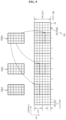
- FIG. 9 illustrates an example of a method for mapping DVRBs and LVRBs to PRBs.
- N D 3.
- An arbitrary DVRB can be divided into three parts and the divided parts can be mapped to different PRBs, respectively. At this time, the remaining part of each PRB, not mapped by the arbitrary DVRB, is mapped by a divided part of a different DVRB.
- 'N LVRB ' represents the number of LVRBs available in the system.
- N DVRB ' represents the number of DVRBs available in the system.
- LVRB_UE ' represents the maximum number of LVRBs allocable to one user equipment (UE).
- subset ' represents the number of subsets.
- 'N DivOrder' represents a diversity order required in the system.
- the diversity order is defined by the number of RBs which are not adjacent to each other.
- the "number of RBs” means the number of RBs divided on a frequency axis. That is, even in the case where RBs can be divided by time slots constituting a subframe, the "number of RBs” means the number of RBs divided on the frequency axis of the same slot.
- each RE of one LVRB is one-to-one mapped to each RE of one PRB.
- one LVRB is mapped to a PRB0 (901).
- one DVRB is divided into three parts and the divided parts are mapped to different PRBs, respectively.
- a DVRB0 is divided into three parts and the divided parts are mapped to a PRB1, PRB4 and PRB6, respectively.
- a DVRB1 and a DVRB2 are each divided into three parts and the divided parts are mapped to the remaining resources of the PRB1, PRB4 and PRB6.
- each DVRB is divided into three parts in this example, the present invention is not limited thereto.
- each DVRB may be divided into two parts.
- the radio channel conditions of the respective terminals have different characteristics, it is necessary to perform data transmission of the FDS scheme with respect to a certain terminal and data transmission of the FSS scheme with respect to a different terminal even within one subframe.
- a detailed FDS transmission scheme and a detailed FSS transmission scheme must be designed such that the two schemes can be efficiently multiplexed within one subframe.
- a gain can be obtained by selectively using a band favorable to a UE among all available bands.
- the base station can transmit bitmap information of N LVRB bits to each terminal to notify the terminal of which one of the LVRBs through which downlink data will be transmitted or which one of the LVRBs through which uplink data can be transmitted. That is, each bit of the N LVRB -bit bitmap information, which is transmitted to each terminal as scheduling information, indicates whether data will or can be transmitted through an LVRB corresponding to this bit, among the N LVRB LVRBs.
- This scheme is disadvantageous in that, when the number N LVRB becomes larger, the number of bits to be transmitted to each terminal becomes larger in proportion thereto.
- a terminal can be allocated only one set of contiguous RBs
- information of the allocated RBs can be expressed by a start point of the RBs and the number thereof. This scheme is referred to as a ⁇ compact scheme' in this document.
- the length of available RBs is different depending on respective start points, and the number of combinations of RB allocation is N LVRB (N LVRB +1)/2 in the end. Accordingly, the number of bits required for the combinations is ceiling(log 2 (N LVRB (N LVRB +1)/2)).
- ceiling(x) means rounding "x" up to a nearest integer. This method is advantageous over the bitmap scheme in that the number of bits does not so significantly increase with the increase in the number N LVRB .
- FIG. 11 illustrates an example of a method for mapping two DVRBs having consecutive indexes to a plurality of contiguous PRBs.
- first divided parts 1101 and 1102 and second divided parts 1103 and 1104 are spaced part from each other by a gap 1105, while divided parts belonging to each of the upper divided parts and lower divided parts are contiguous to each other, so that the diversity order becomes 2.
- FIG. 12 illustrates an example of a method for mapping two DVRBs having consecutive indexes to a plurality of spaced PRBs.
- ⁇ spaced PRBs' means that the PRBs are not adjacent to each other.
- consecutive DVRB indexes can be allowed to be distributed, not correspond to contiguous PRBs.
- a DVRB index '0' and a DVRB index '1' are not arranged contiguous to each other.
- DVRB indexes are arranged in the order of 0, 8, 16, 4, 12, 20, ..., and this arrangement can be obtained by inputting the consecutive indexes shown in FIG. 11 to, for example, a block interleaver.
- FIG. 13 illustrates the case where one UE is allocated four DVRBs under the same rules as those of FIG. 12 .
- a gap which is a relative distance between divided parts of each DVRB mapped to PRBs, is set to 0.
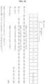
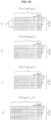
- one bit of the RBG bitmap can be assigned as a shift indicator 1506 so that it can be used to shift the position of an RB indicated by the subset bitmap.
- the subset indicator 1503 indicates the subset 1 and the shift indicator 1506 indicates ⁇ shift 0'
- the remaining 8 bits of the bitmap are used to indicate RB0, RB1, RB2, RB9, RB10, RB11, RB18 and RB19 (see 1504).
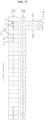
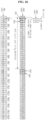
- FIGs. 17 and 18 illustrate a DVRB mapping method according to one embodiment of the present invention.
- DVRB0 to DVRB11 are distributively mapped within a subset 1 (1703)
- DVRB12 to DVRB22 are then distributively mapped within a subset 2 (1704)
- DVRB23 to DVRB31 are then distributively mapped within a subset 3 (1705).
- This mapping can be carried out by a method of using a block interleaver for each subset or any other method.
- gap information can be used to map divided parts of the same DVRB within the same subset.
- a parameter for all PRBs such as the aforementioned 'Gap', may be used.
- another parameter for one subset, 'Gap subset ' may be used. This will hereinafter be described in detail.
- the embodiment 5 is directed to a method for setting a relative distance between divided DVRB parts to a multiple of the square of the size of an RBG.
- the limited setting of Gap to a multiple of the size of an RBG as in the present embodiment provides characteristics as follows. That is, when the relative distance between the divided DVRB parts is indicated as a relative position difference within one subset, it is set to a multiple of the size (P) of an RBG. Alternatively, when the relative distance between the divided DVRB parts is indicated as a position difference with respect to all PRBs, it is limited to a multiple of the square (P 2 ) of the RBG size.
- DVRB indexes can be sequentially mapped to one subset (for example, subset 1) used for DVRBs, among the subsets, as shown in FIG. 18 . If the DVRB indexes cannot be mapped to the one subset any longer, they can be mapped to a next subset (for example, subset 2).
- DVRB indexes are consecutively arranged in FIG. 11 , but non-consecutively arranged in FIGs. 12 , 13 , 14 , 16 , 17 and 18 .
- DVRB indexes can be changed in arrangement before being mapped to PRB indexes, and this change can be performed by a block interleaver.
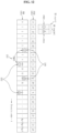
- the structure of a block interleaver according to the present invention will be described.
- the writing is performed in such a manner that, after one column is completely filled, a column index is incremented by one and a next column is filled.
- the writing is performed while a row index is incremented.
- the reading is performed in such a manner that, after one row is completely read, a row index is incremented by one and a next row is read.
- the reading is performed while a column index is incremented.
- the degree of the interleaver is the number of rows, which is set to a target diversity order, 6.
- a DVRB index order of a data sequence outputted from the interleaver can be used as an index order of first divided parts of DVRBs, and a DVRB index order of a data sequence obtained by cyclically shifting the outputted data sequence by N DVRB /N D can be used as an index order of the remaining divided parts.
- N D divided parts generated from DVRBs are mapped to only N D PRBs in pairs, and the difference between paired DVRB indexes is K.
- a DVRB index order 1901 of a data sequence outputted from the interleaver is given as "0 -7 6 -7 12 ⁇ 18 -7 1 -7 7 ⁇ 13 -7 19 -7 2 ⁇ 8 -7 14 ⁇ 20 -7 3 -7 9 -7 15 -7 21 ⁇ 4 ⁇ 10 -7 16 -7 22 ⁇ 5 -7 11 -7 17 ⁇ 23”
- DVRBs are paired. Referring to 1903 of FIG. 19 , for example, it can be seen that a DVRB0 and a DVRB3 are paired. It can also be seen that respective combinations of divided parts generated from the DVRB0 and DVRB3 are mapped to a PRB0 and a PRB12, respectively. This is similarly applied to other DVRBs having other indexes.
- N null the number of nulls filled in the interleaver.
- N DVRB is a multiple of N DivOrder .
- N DVRB is not a multiple of N DivOrder , it is necessary to take a null filling method into consideration because it is impossible to completely fill data in the interleaver.
- N DVRB For a cyclic shift by N DVRB /N D , N DVRB should be a multiple of N D . In order to completely fill data in a rectangular interleaver, N DVRB should be a multiple of N DivOrder . However, when K > 1, N DVRB may not be a multiple of N DivOrder , even though it is a multiple of N D . In this case, generally, data is sequentially filled in the block interleaver, and nulls are then filled in remaining spaces of the block interleaver. Thereafter, reading is performed. If the data is filled column by column, then the data is read row by row, or if the data is filled row by row, then the data is read column by column. In this case, no reading is performed for nulls.
- FIGs. 21a and 21b illustrates a null arranging method according to one embodiment of the present invention. Referring to FIG. 21a and 21b , it can be seen that nulls are uniformly distributed, as compared to the case of FIGs. 20a and 20b .
- a reference value M th for M may be set. Based on the reference value M th , the divided parts of each DVRB may be distributively assigned to different PRBs, respectively, to raise the diversity order. Alternatively, the divided parts of each DVRB may be assigned to the same PRB without being distributed to different PRBs. In this case, it is possible to reduce the number of PRBs, to which DVRBs are distributively mapped, and thus to limit the diversity order.
- DVRB indexes of a data sequence outputted from the interleaver are applied, in common, to all divided parts of each DVRB such that they are mapped to PRBs, as shown in FIG. 22 .
- DVRB indexes of a data sequence outputted from the interleaver have an order of "0 -7 6 -7 12 ⁇ 18 -7 1 -7 7 ⁇ 13 ⁇ 19 ⁇ 2 ⁇ 8 ⁇ 14 ⁇ 20 -7 3 -7 9 -7 15 -7 21 -7 4 -7 10 -7 16 -7 22 -7 5 -7 11 -7 17 -7 23".
- each data sequence DVRB index is applied, in common, to first and second divided parts 2201 and 2202 of each DVRB.
- the PRBs used for the UE1 and UE2 include a PRB0, PRB1, PRB4, PRB5, PRB8, PRB9, PRB12, PRB13, PRB16, PRB17, PRB20, and PRB21, as shown by "2303" in FIG. 23 .
- the PRB8 and PRB20 are partially used.
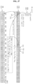
- FIG. 24 is a view for explaining the relation between DVRB and PRB indexes.
- round( ⁇ ) represents an integer nearest to a numeral indicated in “()”.
- min(x,y) represents the value which is not larger among x and y, whereas "max(x,y)” represents the value which is not smaller among x and y.
- the method of FIG. 25b is similar to the method of FIGs. 20a and 20b .
- a PRB index p is given, a DVRB index can be derived using Expression 4.
- a PRB index can be derived using Expression 5.
- p 1 , d ′ mod d C ⁇ R + ⁇ d / C ⁇ p 2
- d mod p 1 , d + N DVRB / 2 , N DVRB
- a PRB index can be derived using Expression 8.
- p 1 , d ′ mod d C ⁇ R + ⁇ d / C ⁇ p 2
- d mod p 1 , d + N DVRB / 2 , N DVRB
- N null represents the number of nulls to be included in the interleaver. This value N null may be a predetermined value.
- a DVRB index p is given, a DVRB index can be derived using Expression 9 or 10.
- d p 1 mod p ′ , R ⁇ C + ⁇ p ′ / R ⁇
- p ′ ⁇ p
- when N null 0 or p ⁇ R ⁇ N null / 2 or R ⁇ p ⁇ 2 R ⁇ N null / 2 p + N null / 2
- p 1 mod p ′ , 2 R ⁇ C / 2 + ⁇ p ′ / 2 R ⁇
- p ′ ⁇ p + R ⁇ N null / 2
- a PRB index can be derived using Expression 11.
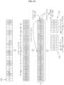
- FIGs. 26 and 27 illustrate examples of a method using a combination of the bitmap scheme using the RBG scheme and subset scheme and the compact scheme, respectively.
- only a part of the resource elements of an RBG0 consisting of PRBs are mapped by the first DVRB divided part, and only parts of the resource elements of RBG8 and RBG9 each consisting of PRBs are mapped by the second DVRB divided part.
- the RBG0, RBG8, and RBG9 cannot be applied to a scheme using a resource allocation on an RBG basis.
- the RBG8 can be applied to a scheme using a resource allocation on an RBG basis, different from the method of FIG. 26 .
- the DVRB1 and DVRB2 are mapped to the PRB1, PRB2, PRB25 and PRB26. In this case, parts of the resource elements of the PRB1, PRB2, PRB25, and PRB26 are left without being mapped.
- the DVRB25 and DVRB26 are additionally mapped to PRBs, they completely fill the remaining spaces of the PRB1, PRB2, PRB25, and PRB26.
- the gap is set to be a multiple of M RBG , and the second divided part of each DVRB is cyclically shifted by N RB /N D so that the DVRB indexes mapped to one PRB are paired.
- the number of RBs used for DVRBs namely, N DVRB
- N DVRB is set such that consecutive DVRB indexes are assigned to the same subset.
- the exemplary embodiments described hereinabove are combinations of elements and features of the present invention.
- the elements or features may be considered selective unless otherwise mentioned.
- Each element or feature may be practiced without being combined with other elements or features.
- the embodiments of the present invention may be constructed by combining parts of the elements and/or features. Operation orders described in the embodiments of the present invention may be rearranged. Some constructions of any one embodiment may be included in another embodiment and may be replaced with corresponding constructions of another embodiment. It is apparent that the present invention may be embodied by a combination of claims which do not have an explicit cited relation in the appended claims or may include new claims by amendment after application.
- the embodiments of the present invention may be achieved by a module, a procedure, a function, etc. performing the above-described functions or operations.
- a software code may be stored in a memory unit and driven by a processor.
- the memory unit is located at the interior or exterior of the processor and may transmit data to and receive data from the processor via various known means.
Landscapes
- Engineering & Computer Science (AREA)
- Signal Processing (AREA)
- Computer Networks & Wireless Communication (AREA)
- Mobile Radio Communication Systems (AREA)
- Error Detection And Correction (AREA)
Priority Applications (1)
| Application Number | Priority Date | Filing Date | Title |
|---|---|---|---|
| EP24186620.1A EP4429141A3 (en) | 2008-01-07 | 2009-01-07 | Method for scheduling distributed virtual resource blocks |
Applications Claiming Priority (10)
| Application Number | Priority Date | Filing Date | Title |
|---|---|---|---|
| US1958908P | 2008-01-07 | 2008-01-07 | |
| US2488608P | 2008-01-30 | 2008-01-30 | |
| US2611308P | 2008-02-04 | 2008-02-04 | |
| US2818608P | 2008-02-12 | 2008-02-12 | |
| US2851108P | 2008-02-13 | 2008-02-13 | |
| US3335808P | 2008-03-03 | 2008-03-03 | |
| US3730208P | 2008-03-17 | 2008-03-17 | |
| US3877808P | 2008-03-24 | 2008-03-24 | |
| KR1020080131112A KR100904433B1 (ko) | 2008-01-07 | 2008-12-22 | 분산형 가상자원블록 스케쥴링 방법 |
| EP09150178.3A EP2077640B1 (en) | 2008-01-07 | 2009-01-07 | Method for scheduling distributed virtual resource blocks |
Related Parent Applications (2)
| Application Number | Title | Priority Date | Filing Date |
|---|---|---|---|
| EP09150178.3A Division EP2077640B1 (en) | 2008-01-07 | 2009-01-07 | Method for scheduling distributed virtual resource blocks |
| EP09150178.3A Division-Into EP2077640B1 (en) | 2008-01-07 | 2009-01-07 | Method for scheduling distributed virtual resource blocks |
Related Child Applications (2)
| Application Number | Title | Priority Date | Filing Date |
|---|---|---|---|
| EP24186620.1A Division EP4429141A3 (en) | 2008-01-07 | 2009-01-07 | Method for scheduling distributed virtual resource blocks |
| EP24186620.1A Previously-Filed-Application EP4429141A3 (en) | 2008-01-07 | 2009-01-07 | Method for scheduling distributed virtual resource blocks |
Publications (2)
| Publication Number | Publication Date |
|---|---|
| EP3379763A1 EP3379763A1 (en) | 2018-09-26 |
| EP3379763B1 true EP3379763B1 (en) | 2024-07-10 |
Family
ID=40532539
Family Applications (3)
| Application Number | Title | Priority Date | Filing Date |
|---|---|---|---|
| EP18171916.2A Active EP3379763B1 (en) | 2008-01-07 | 2009-01-07 | Method for scheduling distributed virtual resource blocks |
| EP09150178.3A Active EP2077640B1 (en) | 2008-01-07 | 2009-01-07 | Method for scheduling distributed virtual resource blocks |
| EP24186620.1A Pending EP4429141A3 (en) | 2008-01-07 | 2009-01-07 | Method for scheduling distributed virtual resource blocks |
Family Applications After (2)
| Application Number | Title | Priority Date | Filing Date |
|---|---|---|---|
| EP09150178.3A Active EP2077640B1 (en) | 2008-01-07 | 2009-01-07 | Method for scheduling distributed virtual resource blocks |
| EP24186620.1A Pending EP4429141A3 (en) | 2008-01-07 | 2009-01-07 | Method for scheduling distributed virtual resource blocks |
Country Status (8)
| Country | Link |
|---|---|
| US (4) | US7885230B2 (enExample) |
| EP (3) | EP3379763B1 (enExample) |
| JP (1) | JP5193307B2 (enExample) |
| KR (1) | KR100904433B1 (enExample) |
| CN (2) | CN101911744B (enExample) |
| CA (1) | CA2703924C (enExample) |
| TW (1) | TWI450550B (enExample) |
| WO (1) | WO2009088201A2 (enExample) |
Families Citing this family (60)
| Publication number | Priority date | Publication date | Assignee | Title |
|---|---|---|---|---|
| US6111876A (en) * | 1996-03-12 | 2000-08-29 | Nortel Networks Limited | VLAN frame format |
| US5959990A (en) * | 1996-03-12 | 1999-09-28 | Bay Networks, Inc. | VLAN frame format |
| JP4916389B2 (ja) * | 2007-06-19 | 2012-04-11 | 株式会社エヌ・ティ・ティ・ドコモ | 無線通信制御方法、基地局装置、およびユーザ装置 |
| CA2897380C (en) | 2007-06-19 | 2017-08-15 | Panasonic Intellectual Property Corporation Of America | Channel arrangement method and radio communication base station device |
| ES2836690T3 (es) | 2008-01-04 | 2021-06-28 | Panasonic Corp | Método de asignación de canal y dispositivo de estación base de comunicación inalámbrica |
| KR100925441B1 (ko) | 2008-01-07 | 2009-11-06 | 엘지전자 주식회사 | 분산형 가상자원블록 스케쥴링 방법 |
| KR100913099B1 (ko) * | 2008-01-07 | 2009-08-21 | 엘지전자 주식회사 | 분산형 가상자원블록 스케쥴링 방법 |
| US8358979B2 (en) * | 2009-02-04 | 2013-01-22 | Telefonaktiebolaget Lm Ericsson (Publ) | Method and apparatus for measuring interference in a telecommunications system |
| GB2457242A (en) * | 2008-02-05 | 2009-08-12 | Nec Corp | Resource allocation in a communication system |
| US8493835B2 (en) | 2008-03-26 | 2013-07-23 | Qualcomm, Incorporated | Method and apparatus for mapping virtual resources to physical resources in a wireless communication system |
| JP5048867B2 (ja) * | 2009-03-17 | 2012-10-17 | 三菱電機株式会社 | 通信システム、通信装置および周波数割り当て方法 |
| KR101645299B1 (ko) * | 2009-03-31 | 2016-08-03 | 오렌지 | 서브-채널들에서 심벌들의 시간―주파수 맵핑을 이용하여 전송하기 위한 방법 및 디바이스 |
| US8817726B2 (en) * | 2009-07-26 | 2014-08-26 | Lg Electronics Inc. | Uplink transmission method and apparatus in wireless communication system |
| WO2011013971A2 (ko) * | 2009-07-26 | 2011-02-03 | 엘지전자 주식회사 | 무선 통신 시스템에서 상향링크 전송 방법 및 장치 |
| KR101650749B1 (ko) * | 2009-08-18 | 2016-08-24 | 삼성전자주식회사 | 릴레이를 위한 백홀 서브프레임의 제어 채널 자원 할당 방법 및 장치 |
| US20110069637A1 (en) * | 2009-09-18 | 2011-03-24 | Futurewei Technologies, Inc. | System and Method for Control Channel Search Space Location Indication for a Relay Backhaul Link |
| GB2476488A (en) | 2009-12-23 | 2011-06-29 | Nec Corp | Allocating physical resource blocks to a user device for transmitting uplink data |
| US9253784B2 (en) | 2010-01-11 | 2016-02-02 | Samsung Electronics Co., Ltd. | Method and system for enabling resource block bundling in LTE-A systems |
| JP2011151545A (ja) * | 2010-01-20 | 2011-08-04 | Nec Corp | 通信装置および受信方法、並びにプログラム |
| US8917677B2 (en) | 2010-04-14 | 2014-12-23 | Samsung Electronics Co., Ltd. | Systems and methods for bundling resource blocks in a wireless communication system |
| AU2011241357B2 (en) * | 2010-04-14 | 2014-12-18 | Lg Electronics Inc. | Method for setting a search space for a relay node in a wireless communication system and apparatus for same |
| EP2378697A1 (en) * | 2010-04-14 | 2011-10-19 | Mitsubishi Electric R&D Centre Europe B.V. | Method for determining information which enable a mobile station to identify which resources are allocated to the mobile station |
| CN102223719B (zh) * | 2010-04-16 | 2014-01-08 | 华为技术有限公司 | 资源分配指示方法、基站设备、用户设备 |
| WO2011142574A2 (ko) * | 2010-05-11 | 2011-11-17 | 엘지전자 주식회사 | 하향링크 신호를 수신하는 방법 및 장치 |
| AU2011251032B2 (en) | 2010-05-14 | 2015-07-23 | Lg Electronics Inc. | Method for allocating resources in a wireless communication system and a device for the same |
| WO2011152663A2 (ko) * | 2010-06-01 | 2011-12-08 | 엘지전자 주식회사 | 무선 통신 시스템에서 자원 할당 방법 및 장치 |
| EP3474620B1 (en) * | 2010-06-21 | 2020-02-12 | Sun Patent Trust | Data transmission from a terminal apparatus according to resource allocation information calculated based on indication information received from a base station |
| US20120120888A1 (en) * | 2010-11-02 | 2012-05-17 | Samsung Electronics Co., Ltd. | Apparatus and method for primary uplink shared channel hopping in a wireless network |
| KR101210115B1 (ko) | 2011-03-04 | 2012-12-07 | 연세대학교 산학협력단 | 상향링크 sc-fdma 시스템에서의 주파수 부 채널 할당 방법 및 장치 |
| WO2012134042A2 (ko) * | 2011-03-30 | 2012-10-04 | 엘지전자 주식회사 | 무선 통신 시스템에서 트래픽 지시 맵을 생성하는 방법 및 장치 |
| JP5616284B2 (ja) | 2011-05-02 | 2014-10-29 | 株式会社Nttドコモ | 基地局装置、移動端末装置、通信システム及び通信方法 |
| KR102067060B1 (ko) | 2011-06-29 | 2020-02-11 | 엘지전자 주식회사 | 무선 통신 시스템에서 제어 정보의 전송 방법 및 장치 |
| KR101730304B1 (ko) * | 2011-08-16 | 2017-04-25 | 후지쯔 가부시끼가이샤 | 자원 할당 방법, 기지국 및 단말기 장치 |
| JP5856810B2 (ja) * | 2011-11-02 | 2016-02-10 | シャープ株式会社 | 基地局装置、移動局装置、無線通信方法、無線通信システムおよび集積回路 |
| CN102412951B (zh) * | 2011-11-17 | 2014-06-11 | 武汉邮电科学研究院 | Lte中分布式虚拟资源块映射到物理资源块的方法和装置 |
| CN102523606B (zh) * | 2011-12-05 | 2014-08-06 | 电信科学技术研究院 | 一种数据交互方法及装置 |
| EP2822339B1 (en) * | 2012-02-28 | 2017-08-23 | LG Electronics Inc. | Method and apparatus for allocating resources in wireless communication system |
| KR101562694B1 (ko) * | 2012-09-18 | 2015-10-22 | 주식회사 케이티 | 송수신포인트의 제어 정보 전송 방법 및 그 송수신포인트, 단말의 제어 정보 수신 방법 및 그 단말 |
| US10285167B2 (en) * | 2013-09-20 | 2019-05-07 | Qualcomm Incorporated | Uplink resource allocation and transport block size determination over unlicensed spectrum |
| US10334591B2 (en) * | 2014-05-27 | 2019-06-25 | Lg Electronics Inc. | Data transmission method and apparatus by device terminal in wireless communication system |
| WO2016074226A1 (zh) | 2014-11-14 | 2016-05-19 | 华为技术有限公司 | 基于ofmda的wlan系统中的交织处理方法和设备 |
| US20160270038A1 (en) | 2015-03-11 | 2016-09-15 | Samsung Electronics Co., Ltd | Transmissions of downlink control channels for low cost ues |
| CN106155912A (zh) * | 2015-04-14 | 2016-11-23 | 扬智科技股份有限公司 | 多通道存储器与其存储器存取方法 |
| US10420134B2 (en) * | 2016-02-02 | 2019-09-17 | Cisco Technology, Inc. | System and method to facilitate subframe scheduling in a split medium access control radio access network environment |
| CN107040997B (zh) * | 2016-02-03 | 2023-07-14 | 中兴通讯股份有限公司 | 资源配置的方法及装置 |
| WO2017132955A1 (zh) | 2016-02-04 | 2017-08-10 | 华为技术有限公司 | 控制信息传输方法及基站与终端 |
| CN108605026B (zh) * | 2016-02-24 | 2020-07-24 | 华为技术有限公司 | 一种信号传输方法、装置及终端设备 |
| US11419134B2 (en) * | 2016-03-25 | 2022-08-16 | Lg Electronics Inc. | Method for transmitting and receiving uplink signal in wireless communication system supporting non-licensed band, and apparatus for supporting same |
| US10374765B2 (en) * | 2016-12-15 | 2019-08-06 | Qualcomm Incorporated | Quantized K-resource element row-column interleaver |
| WO2018128780A1 (en) * | 2017-01-09 | 2018-07-12 | Intel Corporation | Generation node-b (gnb), user equipment (ue) and methods for interleaving in multiple-input multiple-output (mimo) arrangements |
| CN109391438B (zh) * | 2017-08-11 | 2020-03-10 | 维沃移动通信有限公司 | 资源映射方法及设备 |
| WO2019036492A1 (en) * | 2017-08-14 | 2019-02-21 | Cohere Technologies | ASSIGNMENT OF TRANSMISSION RESOURCES BY DIVISION OF BLOCKS OF PHYSICAL RESOURCES |
| US12114291B2 (en) * | 2017-11-10 | 2024-10-08 | Qualcomm Incorporated | Virtual resource block to physical resource block mapping in new radio |
| US11277246B2 (en) | 2017-11-17 | 2022-03-15 | Panasonic Intellectual Property Corporation Of America | Base station, user equipment and wireless communication method |
| CN109995467B (zh) * | 2018-01-03 | 2020-09-01 | 电信科学技术研究院 | 一种资源映射方法及装置、设备 |
| KR101954433B1 (ko) | 2018-01-11 | 2019-03-05 | 엘지전자 주식회사 | 무선 통신 시스템에서 단말의 하향링크 신호 수신 방법 및 상기 방법을 이용하는 단말 |
| JP2021526749A (ja) * | 2018-04-03 | 2021-10-07 | 日本電気株式会社 | 無線通信システムにおけるリソース割り当てのための方法及びデバイス |
| CN111065160B (zh) * | 2018-10-17 | 2022-12-02 | 中兴通讯股份有限公司 | 资源的分配方法及装置、存储介质和电子装置 |
| US11116002B2 (en) * | 2019-02-14 | 2021-09-07 | Qualcomm Incorporated | Gap configuration for multiple transport blocks |
| US20230291516A1 (en) * | 2020-08-31 | 2023-09-14 | Qualcomm Incorporated | Bit interleaving for sidelink communication with interlaced waveform |
Family Cites Families (41)
| Publication number | Priority date | Publication date | Assignee | Title |
|---|---|---|---|---|
| US5710768A (en) | 1994-09-30 | 1998-01-20 | Qualcomm Incorporated | Method of searching for a bursty signal |
| ES2176280T3 (es) | 1995-08-21 | 2002-12-01 | Cit Alcatel | Metodo para intercalar cuadros de datos, dispositivo de correccion cronologica de error y modulador que incluye tal dispositivo. |
| US6377809B1 (en) | 1997-09-16 | 2002-04-23 | Qualcomm Incorporated | Channel structure for communication systems |
| US6574211B2 (en) | 1997-11-03 | 2003-06-03 | Qualcomm Incorporated | Method and apparatus for high rate packet data transmission |
| WO1999025069A1 (en) | 1997-11-10 | 1999-05-20 | Ntt Mobile Communications Network, Inc. | Interleaving method, interleaving apparatus, and recording medium in which interleave pattern generating program is recorded |
| FR2806576B1 (fr) * | 2000-03-15 | 2004-04-23 | Nortel Matra Cellular | Procede d'emission de signaux radio, reseau d'acces et terminal de radiocommunication appliquant le procede |
| US20020122410A1 (en) | 2001-02-13 | 2002-09-05 | Cybiko Inc. | Method of wireless data exchange amongst devices of limited range |
| US7313190B2 (en) | 2003-03-11 | 2007-12-25 | Texas Instruments Incorporated | Efficient bit interleaver for a multi-band OFDM ultra-wideband system |
| KR100575434B1 (ko) * | 2003-11-19 | 2006-05-03 | 한국전자통신연구원 | 직교주파수 분할 다중 접속 기반 셀룰러 시스템에서의 자원 공간 분할 및 물리 채널 할당 방법 |
| US7570695B2 (en) * | 2003-12-18 | 2009-08-04 | Intel Corporation | Method and adaptive bit interleaver for wideband systems using adaptive bit loading |
| US7159096B2 (en) * | 2004-03-31 | 2007-01-02 | Marvell International Ltd. | Method and apparatus to perform memory management |
| US7818475B2 (en) * | 2004-04-30 | 2010-10-19 | Emc Corporation | Storage switch mirrored write sequence count management |
| KR20060106223A (ko) | 2005-04-06 | 2006-10-12 | 삼성전자주식회사 | 직교 주파수 분할 다중 시스템에서 비트 삽입 및 코드 변조방식의 송신 장치 및 방법 |
| US8044571B2 (en) | 2005-12-14 | 2011-10-25 | General Electric Company | Electrode stacks for electroactive devices and methods of fabricating the same |
| KR100834677B1 (ko) * | 2006-01-16 | 2008-06-02 | 삼성전자주식회사 | 주파수 분할 다중접속 방식의 무선 통신 시스템에서 자원할당 장치 및 방법 |
| WO2007082754A1 (en) | 2006-01-18 | 2007-07-26 | Telefonaktiebolaget L M Ericsson (Publ) | Localized and distributed transmission |
| US20070177553A1 (en) | 2006-01-31 | 2007-08-02 | Nokia Corporation | Apparatus, method and computer program product providing efficient signaling of user allocations in an optimum manner |
| JP4343926B2 (ja) | 2006-02-08 | 2009-10-14 | 株式会社エヌ・ティ・ティ・ドコモ | 送信装置および送信方法 |
| US7668188B2 (en) * | 2006-02-14 | 2010-02-23 | Broadcom Corporation | Method and system for HSDPA bit level processor engine |
| WO2007094628A1 (en) * | 2006-02-15 | 2007-08-23 | Samsung Electronics Co., Ltd. | Method and apparatus for resource allocation in an ofdm system |
| EP2014042A2 (en) | 2006-03-16 | 2009-01-14 | Nokia Corporation | Apparatus, methods and computer program products providing signaling of time staggered measurement reports and scheduling in response thereto |
| WO2007119148A2 (en) | 2006-04-13 | 2007-10-25 | Nokia Corporation | Method providing efficient and flexible control signal for resource allocation |
| BRPI0710961B1 (pt) | 2006-04-28 | 2020-02-04 | Panasonic Corp | aparelho de estação móvel e método de comunicação |
| KR100885476B1 (ko) | 2006-05-02 | 2009-02-24 | 한국전자통신연구원 | 직교 주파수 분할 다중 접속 시스템에서의 하향링크스케줄링 정보 송/수신 방법 |
| JPWO2008001728A1 (ja) | 2006-06-26 | 2009-11-26 | パナソニック株式会社 | 無線通信基地局装置およびリソースブロック割当方法 |
| KR100961747B1 (ko) | 2006-06-27 | 2010-06-07 | 삼성전자주식회사 | 무선 통신 시스템의 자원 할당 장치 및 방법 |
| US8369424B2 (en) | 2006-07-14 | 2013-02-05 | Qualcomm Incorporated | Frequency selective and frequency diversity transmissions in a wireless communication system |
| US20080031191A1 (en) * | 2006-08-01 | 2008-02-07 | Nokia Corporation | Shared control channel structure for multi-user MIMO resource allocation |
| WO2008024283A2 (en) | 2006-08-21 | 2008-02-28 | Interdigital Technology Corporation | Resource allocation, scheduling, and signaling for grouping real time services |
| CN101146317A (zh) * | 2006-09-15 | 2008-03-19 | 北京三星通信技术研究有限公司 | 资源分配及控制信令传输方法 |
| EP1965536A1 (en) | 2007-02-06 | 2008-09-03 | Mitsubishi Electric Information Technology Centre Europe B.V. | Method of data transmission in a multi-carrier based transmission system and device implementing the method |
| US8073062B2 (en) | 2007-02-08 | 2011-12-06 | Motorola Mobility, Inc. | Method and apparatus for downlink resource allocation in an orthogonal frequency division multiplexing communication system |
| KR20080085654A (ko) | 2007-03-19 | 2008-09-24 | 엘지전자 주식회사 | 셀룰라 다중 반송파 시스템에서 스케줄링 방법 및 스케줄링정보 송신 방법 |
| EP2372941B1 (en) | 2007-03-19 | 2019-02-27 | LG Electronics Inc. | A resource allocation method and a method for transmitting/receiving resource allocation information in mobile communication system |
| CA2897380C (en) | 2007-06-19 | 2017-08-15 | Panasonic Intellectual Property Corporation Of America | Channel arrangement method and radio communication base station device |
| US8526371B2 (en) | 2007-08-13 | 2013-09-03 | Qualcomm Incorporated | Frequency diverse transmissions in a wireless communication system |
| ES2836690T3 (es) | 2008-01-04 | 2021-06-28 | Panasonic Corp | Método de asignación de canal y dispositivo de estación base de comunicación inalámbrica |
| WO2009088911A1 (en) * | 2008-01-09 | 2009-07-16 | Nortel Networks Limited | Mapping of distributed resource block indices to physical resource blocks |
| CN101247382A (zh) * | 2008-03-25 | 2008-08-20 | 中兴通讯股份有限公司 | 基于ofdm系统的分布式传输资源映射方法和装置 |
| US8493835B2 (en) | 2008-03-26 | 2013-07-23 | Qualcomm, Incorporated | Method and apparatus for mapping virtual resources to physical resources in a wireless communication system |
| US20090268624A1 (en) | 2008-04-28 | 2009-10-29 | Sharp Laboratories Of America, Inc. | Systems and methods for measurement and feedback of channel quality indicator information |
-
2008
- 2008-12-22 KR KR1020080131112A patent/KR100904433B1/ko active Active
-
2009
- 2009-01-06 JP JP2010533017A patent/JP5193307B2/ja active Active
- 2009-01-06 CA CA2703924A patent/CA2703924C/en active Active
- 2009-01-06 CN CN2009801018052A patent/CN101911744B/zh active Active
- 2009-01-06 US US12/349,474 patent/US7885230B2/en active Active
- 2009-01-06 CN CN201310389333.3A patent/CN103457712B/zh active Active
- 2009-01-06 WO PCT/KR2009/000042 patent/WO2009088201A2/en not_active Ceased
- 2009-01-07 EP EP18171916.2A patent/EP3379763B1/en active Active
- 2009-01-07 EP EP09150178.3A patent/EP2077640B1/en active Active
- 2009-01-07 EP EP24186620.1A patent/EP4429141A3/en active Pending
- 2009-01-07 TW TW098100405A patent/TWI450550B/zh active
-
2011
- 2011-01-05 US US12/985,286 patent/US8315222B2/en active Active
- 2011-01-05 US US12/985,291 patent/US8311008B2/en active Active
- 2011-01-05 US US12/985,281 patent/US8305988B2/en active Active
Also Published As
| Publication number | Publication date |
|---|---|
| US20110134857A1 (en) | 2011-06-09 |
| US8311008B2 (en) | 2012-11-13 |
| WO2009088201A2 (en) | 2009-07-16 |
| CA2703924A1 (en) | 2009-07-16 |
| US8315222B2 (en) | 2012-11-20 |
| EP4429141A2 (en) | 2024-09-11 |
| CN103457712B (zh) | 2016-08-10 |
| JP2011504322A (ja) | 2011-02-03 |
| US20110134856A1 (en) | 2011-06-09 |
| CN101911744B (zh) | 2013-10-02 |
| US20110134858A1 (en) | 2011-06-09 |
| TWI450550B (zh) | 2014-08-21 |
| WO2009088201A3 (en) | 2009-09-24 |
| US8305988B2 (en) | 2012-11-06 |
| TW200948005A (en) | 2009-11-16 |
| JP5193307B2 (ja) | 2013-05-08 |
| EP2077640A2 (en) | 2009-07-08 |
| EP2077640B1 (en) | 2018-06-27 |
| US7885230B2 (en) | 2011-02-08 |
| KR100904433B1 (ko) | 2009-06-24 |
| CN103457712A (zh) | 2013-12-18 |
| EP3379763A1 (en) | 2018-09-26 |
| EP2077640A3 (en) | 2012-09-05 |
| CN101911744A (zh) | 2010-12-08 |
| EP4429141A3 (en) | 2024-11-06 |
| US20090175231A1 (en) | 2009-07-09 |
| CA2703924C (en) | 2013-09-03 |
Similar Documents
| Publication | Publication Date | Title |
|---|---|---|
| EP3379763B1 (en) | Method for scheduling distributed virtual resource blocks | |
| EP2077650B1 (en) | Method for scheduling distributed virtual resource blocks | |
| US10631321B2 (en) | Method and apparatus for determining allocation of communication resources | |
| HK40004659A (en) | Method for scheduling distributed virtual resource blocks |
Legal Events
| Date | Code | Title | Description |
|---|---|---|---|
| PUAI | Public reference made under article 153(3) epc to a published international application that has entered the european phase |
Free format text: ORIGINAL CODE: 0009012 |
|
| STAA | Information on the status of an ep patent application or granted ep patent |
Free format text: STATUS: THE APPLICATION HAS BEEN PUBLISHED |
|
| AC | Divisional application: reference to earlier application |
Ref document number: 2077640 Country of ref document: EP Kind code of ref document: P |
|
| AK | Designated contracting states |
Kind code of ref document: A1 Designated state(s): AT BE BG CH CY CZ DE DK EE ES FI FR GB GR HR HU IE IS IT LI LT LU LV MC MK MT NL NO PL PT RO SE SI SK TR |
|
| STAA | Information on the status of an ep patent application or granted ep patent |
Free format text: STATUS: REQUEST FOR EXAMINATION WAS MADE |
|
| 17P | Request for examination filed |
Effective date: 20190326 |
|
| RBV | Designated contracting states (corrected) |
Designated state(s): AT BE BG CH CY CZ DE DK EE ES FI FR GB GR HR HU IE IS IT LI LT LU LV MC MK MT NL NO PL PT RO SE SI SK TR |
|
| STAA | Information on the status of an ep patent application or granted ep patent |
Free format text: STATUS: EXAMINATION IS IN PROGRESS |
|
| 17Q | First examination report despatched |
Effective date: 20210310 |
|
| GRAP | Despatch of communication of intention to grant a patent |
Free format text: ORIGINAL CODE: EPIDOSNIGR1 |
|
| STAA | Information on the status of an ep patent application or granted ep patent |
Free format text: STATUS: GRANT OF PATENT IS INTENDED |
|
| RIC1 | Information provided on ipc code assigned before grant |
Ipc: H04W 72/23 20230101ALN20240117BHEP Ipc: H04W 72/00 20090101ALN20240117BHEP Ipc: H04L 1/04 20060101ALI20240117BHEP Ipc: H04L 1/00 20060101ALI20240117BHEP Ipc: H04L 5/00 20060101AFI20240117BHEP |
|
| RIC1 | Information provided on ipc code assigned before grant |
Ipc: H04W 72/23 20230101ALN20240129BHEP Ipc: H04W 72/00 20090101ALN20240129BHEP Ipc: H04L 1/04 20060101ALI20240129BHEP Ipc: H04L 1/00 20060101ALI20240129BHEP Ipc: H04L 5/00 20060101AFI20240129BHEP |
|
| INTG | Intention to grant announced |
Effective date: 20240212 |
|
| GRAS | Grant fee paid |
Free format text: ORIGINAL CODE: EPIDOSNIGR3 |
|
| GRAA | (expected) grant |
Free format text: ORIGINAL CODE: 0009210 |
|
| STAA | Information on the status of an ep patent application or granted ep patent |
Free format text: STATUS: THE PATENT HAS BEEN GRANTED |
|
| AC | Divisional application: reference to earlier application |
Ref document number: 2077640 Country of ref document: EP Kind code of ref document: P |
|
| AK | Designated contracting states |
Kind code of ref document: B1 Designated state(s): AT BE BG CH CY CZ DE DK EE ES FI FR GB GR HR HU IE IS IT LI LT LU LV MC MK MT NL NO PL PT RO SE SI SK TR |
|
| REG | Reference to a national code |
Ref country code: CH Ref legal event code: EP |
|
| REG | Reference to a national code |
Ref country code: DE Ref legal event code: R096 Ref document number: 602009065302 Country of ref document: DE |
|
| REG | Reference to a national code |
Ref country code: LT Ref legal event code: MG9D |
|
| REG | Reference to a national code |
Ref country code: NL Ref legal event code: MP Effective date: 20240710 |
|
| PG25 | Lapsed in a contracting state [announced via postgrant information from national office to epo] |
Ref country code: PT Free format text: LAPSE BECAUSE OF FAILURE TO SUBMIT A TRANSLATION OF THE DESCRIPTION OR TO PAY THE FEE WITHIN THE PRESCRIBED TIME-LIMIT Effective date: 20241111 |
|
| REG | Reference to a national code |
Ref country code: AT Ref legal event code: MK05 Ref document number: 1702994 Country of ref document: AT Kind code of ref document: T Effective date: 20240710 |
|
| PG25 | Lapsed in a contracting state [announced via postgrant information from national office to epo] |
Ref country code: NL Free format text: LAPSE BECAUSE OF FAILURE TO SUBMIT A TRANSLATION OF THE DESCRIPTION OR TO PAY THE FEE WITHIN THE PRESCRIBED TIME-LIMIT Effective date: 20240710 |
|
| PG25 | Lapsed in a contracting state [announced via postgrant information from national office to epo] |
Ref country code: PT Free format text: LAPSE BECAUSE OF FAILURE TO SUBMIT A TRANSLATION OF THE DESCRIPTION OR TO PAY THE FEE WITHIN THE PRESCRIBED TIME-LIMIT Effective date: 20241111 Ref country code: NL Free format text: LAPSE BECAUSE OF FAILURE TO SUBMIT A TRANSLATION OF THE DESCRIPTION OR TO PAY THE FEE WITHIN THE PRESCRIBED TIME-LIMIT Effective date: 20240710 |
|
| PG25 | Lapsed in a contracting state [announced via postgrant information from national office to epo] |
Ref country code: NO Free format text: LAPSE BECAUSE OF FAILURE TO SUBMIT A TRANSLATION OF THE DESCRIPTION OR TO PAY THE FEE WITHIN THE PRESCRIBED TIME-LIMIT Effective date: 20241010 |
|
| PG25 | Lapsed in a contracting state [announced via postgrant information from national office to epo] |
Ref country code: PL Free format text: LAPSE BECAUSE OF FAILURE TO SUBMIT A TRANSLATION OF THE DESCRIPTION OR TO PAY THE FEE WITHIN THE PRESCRIBED TIME-LIMIT Effective date: 20240710 Ref country code: GR Free format text: LAPSE BECAUSE OF FAILURE TO SUBMIT A TRANSLATION OF THE DESCRIPTION OR TO PAY THE FEE WITHIN THE PRESCRIBED TIME-LIMIT Effective date: 20241011 Ref country code: FI Free format text: LAPSE BECAUSE OF FAILURE TO SUBMIT A TRANSLATION OF THE DESCRIPTION OR TO PAY THE FEE WITHIN THE PRESCRIBED TIME-LIMIT Effective date: 20240710 |
|
| PGFP | Annual fee paid to national office [announced via postgrant information from national office to epo] |
Ref country code: GB Payment date: 20241205 Year of fee payment: 17 |
|
| PG25 | Lapsed in a contracting state [announced via postgrant information from national office to epo] |
Ref country code: BG Free format text: LAPSE BECAUSE OF FAILURE TO SUBMIT A TRANSLATION OF THE DESCRIPTION OR TO PAY THE FEE WITHIN THE PRESCRIBED TIME-LIMIT Effective date: 20240710 |
|
| PGFP | Annual fee paid to national office [announced via postgrant information from national office to epo] |
Ref country code: FR Payment date: 20241206 Year of fee payment: 17 |
|
| PG25 | Lapsed in a contracting state [announced via postgrant information from national office to epo] |
Ref country code: LV Free format text: LAPSE BECAUSE OF FAILURE TO SUBMIT A TRANSLATION OF THE DESCRIPTION OR TO PAY THE FEE WITHIN THE PRESCRIBED TIME-LIMIT Effective date: 20240710 |
|
| PG25 | Lapsed in a contracting state [announced via postgrant information from national office to epo] |
Ref country code: IS Free format text: LAPSE BECAUSE OF FAILURE TO SUBMIT A TRANSLATION OF THE DESCRIPTION OR TO PAY THE FEE WITHIN THE PRESCRIBED TIME-LIMIT Effective date: 20241110 Ref country code: AT Free format text: LAPSE BECAUSE OF FAILURE TO SUBMIT A TRANSLATION OF THE DESCRIPTION OR TO PAY THE FEE WITHIN THE PRESCRIBED TIME-LIMIT Effective date: 20240710 |
|
| PG25 | Lapsed in a contracting state [announced via postgrant information from national office to epo] |
Ref country code: HR Free format text: LAPSE BECAUSE OF FAILURE TO SUBMIT A TRANSLATION OF THE DESCRIPTION OR TO PAY THE FEE WITHIN THE PRESCRIBED TIME-LIMIT Effective date: 20240710 |
|
| PG25 | Lapsed in a contracting state [announced via postgrant information from national office to epo] |
Ref country code: ES Free format text: LAPSE BECAUSE OF FAILURE TO SUBMIT A TRANSLATION OF THE DESCRIPTION OR TO PAY THE FEE WITHIN THE PRESCRIBED TIME-LIMIT Effective date: 20240710 |
|
| PG25 | Lapsed in a contracting state [announced via postgrant information from national office to epo] |
Ref country code: PL Free format text: LAPSE BECAUSE OF FAILURE TO SUBMIT A TRANSLATION OF THE DESCRIPTION OR TO PAY THE FEE WITHIN THE PRESCRIBED TIME-LIMIT Effective date: 20240710 Ref country code: NO Free format text: LAPSE BECAUSE OF FAILURE TO SUBMIT A TRANSLATION OF THE DESCRIPTION OR TO PAY THE FEE WITHIN THE PRESCRIBED TIME-LIMIT Effective date: 20241010 Ref country code: LV Free format text: LAPSE BECAUSE OF FAILURE TO SUBMIT A TRANSLATION OF THE DESCRIPTION OR TO PAY THE FEE WITHIN THE PRESCRIBED TIME-LIMIT Effective date: 20240710 Ref country code: IS Free format text: LAPSE BECAUSE OF FAILURE TO SUBMIT A TRANSLATION OF THE DESCRIPTION OR TO PAY THE FEE WITHIN THE PRESCRIBED TIME-LIMIT Effective date: 20241110 Ref country code: HR Free format text: LAPSE BECAUSE OF FAILURE TO SUBMIT A TRANSLATION OF THE DESCRIPTION OR TO PAY THE FEE WITHIN THE PRESCRIBED TIME-LIMIT Effective date: 20240710 Ref country code: GR Free format text: LAPSE BECAUSE OF FAILURE TO SUBMIT A TRANSLATION OF THE DESCRIPTION OR TO PAY THE FEE WITHIN THE PRESCRIBED TIME-LIMIT Effective date: 20241011 Ref country code: FI Free format text: LAPSE BECAUSE OF FAILURE TO SUBMIT A TRANSLATION OF THE DESCRIPTION OR TO PAY THE FEE WITHIN THE PRESCRIBED TIME-LIMIT Effective date: 20240710 Ref country code: ES Free format text: LAPSE BECAUSE OF FAILURE TO SUBMIT A TRANSLATION OF THE DESCRIPTION OR TO PAY THE FEE WITHIN THE PRESCRIBED TIME-LIMIT Effective date: 20240710 Ref country code: BG Free format text: LAPSE BECAUSE OF FAILURE TO SUBMIT A TRANSLATION OF THE DESCRIPTION OR TO PAY THE FEE WITHIN THE PRESCRIBED TIME-LIMIT Effective date: 20240710 Ref country code: AT Free format text: LAPSE BECAUSE OF FAILURE TO SUBMIT A TRANSLATION OF THE DESCRIPTION OR TO PAY THE FEE WITHIN THE PRESCRIBED TIME-LIMIT Effective date: 20240710 |
|
| PGFP | Annual fee paid to national office [announced via postgrant information from national office to epo] |
Ref country code: DE Payment date: 20241205 Year of fee payment: 17 |
|
| REG | Reference to a national code |
Ref country code: DE Ref legal event code: R097 Ref document number: 602009065302 Country of ref document: DE |
|
| PG25 | Lapsed in a contracting state [announced via postgrant information from national office to epo] |
Ref country code: DK Free format text: LAPSE BECAUSE OF FAILURE TO SUBMIT A TRANSLATION OF THE DESCRIPTION OR TO PAY THE FEE WITHIN THE PRESCRIBED TIME-LIMIT Effective date: 20240710 Ref country code: RO Free format text: LAPSE BECAUSE OF FAILURE TO SUBMIT A TRANSLATION OF THE DESCRIPTION OR TO PAY THE FEE WITHIN THE PRESCRIBED TIME-LIMIT Effective date: 20240710 |
|
| PG25 | Lapsed in a contracting state [announced via postgrant information from national office to epo] |
Ref country code: EE Free format text: LAPSE BECAUSE OF FAILURE TO SUBMIT A TRANSLATION OF THE DESCRIPTION OR TO PAY THE FEE WITHIN THE PRESCRIBED TIME-LIMIT Effective date: 20240710 |
|
| PG25 | Lapsed in a contracting state [announced via postgrant information from national office to epo] |
Ref country code: CZ Free format text: LAPSE BECAUSE OF FAILURE TO SUBMIT A TRANSLATION OF THE DESCRIPTION OR TO PAY THE FEE WITHIN THE PRESCRIBED TIME-LIMIT Effective date: 20240710 |
|
| PG25 | Lapsed in a contracting state [announced via postgrant information from national office to epo] |
Ref country code: SK Free format text: LAPSE BECAUSE OF FAILURE TO SUBMIT A TRANSLATION OF THE DESCRIPTION OR TO PAY THE FEE WITHIN THE PRESCRIBED TIME-LIMIT Effective date: 20240710 Ref country code: IT Free format text: LAPSE BECAUSE OF FAILURE TO SUBMIT A TRANSLATION OF THE DESCRIPTION OR TO PAY THE FEE WITHIN THE PRESCRIBED TIME-LIMIT Effective date: 20240710 |
|
| PLBE | No opposition filed within time limit |
Free format text: ORIGINAL CODE: 0009261 |
|
| STAA | Information on the status of an ep patent application or granted ep patent |
Free format text: STATUS: NO OPPOSITION FILED WITHIN TIME LIMIT |
|
| 26N | No opposition filed |
Effective date: 20250411 |
|
| REG | Reference to a national code |
Ref country code: CH Ref legal event code: PL |
|
| PG25 | Lapsed in a contracting state [announced via postgrant information from national office to epo] |
Ref country code: SE Free format text: LAPSE BECAUSE OF FAILURE TO SUBMIT A TRANSLATION OF THE DESCRIPTION OR TO PAY THE FEE WITHIN THE PRESCRIBED TIME-LIMIT Effective date: 20240710 |
|
| PG25 | Lapsed in a contracting state [announced via postgrant information from national office to epo] |
Ref country code: MC Free format text: LAPSE BECAUSE OF FAILURE TO SUBMIT A TRANSLATION OF THE DESCRIPTION OR TO PAY THE FEE WITHIN THE PRESCRIBED TIME-LIMIT Effective date: 20240710 Ref country code: LU Free format text: LAPSE BECAUSE OF NON-PAYMENT OF DUE FEES Effective date: 20250107 |
|
| PG25 | Lapsed in a contracting state [announced via postgrant information from national office to epo] |
Ref country code: BE Free format text: LAPSE BECAUSE OF NON-PAYMENT OF DUE FEES Effective date: 20250131 |
|
| PG25 | Lapsed in a contracting state [announced via postgrant information from national office to epo] |
Ref country code: CH Free format text: LAPSE BECAUSE OF NON-PAYMENT OF DUE FEES Effective date: 20250131 |
|
| REG | Reference to a national code |
Ref country code: BE Ref legal event code: MM Effective date: 20250131 |