EP3379648B1 - Antenne réseau plan et dispositif de communication - Google Patents
Antenne réseau plan et dispositif de communication Download PDFInfo
- Publication number
- EP3379648B1 EP3379648B1 EP16874779.8A EP16874779A EP3379648B1 EP 3379648 B1 EP3379648 B1 EP 3379648B1 EP 16874779 A EP16874779 A EP 16874779A EP 3379648 B1 EP3379648 B1 EP 3379648B1
- Authority
- EP
- European Patent Office
- Prior art keywords
- radiation
- array
- units
- antenna
- arrays
- Prior art date
- Legal status (The legal status is an assumption and is not a legal conclusion. Google has not performed a legal analysis and makes no representation as to the accuracy of the status listed.)
- Active
Links
- 238000004891 communication Methods 0.000 title claims description 14
- 230000005855 radiation Effects 0.000 claims description 301
- 238000003491 array Methods 0.000 claims description 53
- 238000010586 diagram Methods 0.000 description 10
- 238000010295 mobile communication Methods 0.000 description 6
- 230000010287 polarization Effects 0.000 description 6
- 230000001413 cellular effect Effects 0.000 description 2
- 239000011159 matrix material Substances 0.000 description 2
- 230000002547 anomalous effect Effects 0.000 description 1
- 230000005540 biological transmission Effects 0.000 description 1
- 230000010267 cellular communication Effects 0.000 description 1
- 230000008878 coupling Effects 0.000 description 1
- 238000010168 coupling process Methods 0.000 description 1
- 238000005859 coupling reaction Methods 0.000 description 1
- 230000001419 dependent effect Effects 0.000 description 1
- 230000000694 effects Effects 0.000 description 1
- 238000005516 engineering process Methods 0.000 description 1
- 238000000034 method Methods 0.000 description 1
- 230000001629 suppression Effects 0.000 description 1
Images


Classifications
-
- H—ELECTRICITY
- H01—ELECTRIC ELEMENTS
- H01Q—ANTENNAS, i.e. RADIO AERIALS
- H01Q21/00—Antenna arrays or systems
- H01Q21/24—Combinations of antenna units polarised in different directions for transmitting or receiving circularly and elliptically polarised waves or waves linearly polarised in any direction
-
- H—ELECTRICITY
- H01—ELECTRIC ELEMENTS
- H01Q—ANTENNAS, i.e. RADIO AERIALS
- H01Q1/00—Details of, or arrangements associated with, antennas
- H01Q1/12—Supports; Mounting means
- H01Q1/22—Supports; Mounting means by structural association with other equipment or articles
- H01Q1/24—Supports; Mounting means by structural association with other equipment or articles with receiving set
- H01Q1/241—Supports; Mounting means by structural association with other equipment or articles with receiving set used in mobile communications, e.g. GSM
- H01Q1/246—Supports; Mounting means by structural association with other equipment or articles with receiving set used in mobile communications, e.g. GSM specially adapted for base stations
-
- H—ELECTRICITY
- H01—ELECTRIC ELEMENTS
- H01Q—ANTENNAS, i.e. RADIO AERIALS
- H01Q5/00—Arrangements for simultaneous operation of antennas on two or more different wavebands, e.g. dual-band or multi-band arrangements
- H01Q5/30—Arrangements for providing operation on different wavebands
- H01Q5/307—Individual or coupled radiating elements, each element being fed in an unspecified way
Definitions
- the present invention relates to the field of communications technologies, and in particular, to a planar array antenna and a communications device to which the planar array antenna is applied.
- An antenna is an indispensable part of a mobile communications device.
- performance of a base station antenna directly affects a communication effect.
- Users have higher requirements on high-speed data transmission.
- requirement types of the users become increasingly diversified, and modern mobile communication is developing towards a multimode multiband direction.
- Mobile communications devices are updated at an increasingly faster speed.
- a multimode multiband base station antenna provides a more effective means for site sharing during mobile communication, and satisfies a requirement of smooth upgrade of a device deployed on a live network and is environmentally-friendly and energy-saving. Therefore, the multimode multiband base station antenna is a direction of base station antenna development in the future.
- One multimode multiband base station antenna needs to include a plurality of antenna arrays that can work on a same frequency band or different frequency bands. However, limited mounting space and broadband work of the antenna array bring new challenges to antenna design.
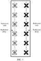
- a solution in the prior art is: implementing a dual-band array antenna by using a conventional two-column layout, that is, the dual-band array antenna includes two radiation arrays that are horizontally arranged, as shown in FIG. 1 .
- the antenna has a relatively large horizontal width dimension and is not suitable for constructing a miniaturized multi-array antenna. If the horizontal width dimension of the antenna is reduced by reducing a distance between the radiation arrays, mutual coupling between the radiation arrays is increased, and there are problems that a horizontal beam width of the antenna is increased, a gain is reduced, or the like.
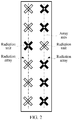
- another solution in the prior art is: implementing a dual-band array antenna by horizontally arranging one or more radiation units in a staggered manner, as shown in FIG. 2 .
- the horizontal width dimension of the antenna is relatively small by arranging one or more radiation units in a staggered manner, because the one or more radiation units deviate from an axis of the radiation array, the arrangement of the radiation units is asymmetric with respect to the axis of the radiation array, leading to anomalous asymmetric side lobes in a directivity pattern of the antenna and a reduced gain of the antenna.
- US 2015/222025 A1 provides a dual-polarized antenna array that includes at least one unit cell.
- the at least one unit cell includes at least one radiating element of a first polarization state and at least two radiating elements of a second polarization state.
- the second polarization state is orthogonal to the first polarization state.
- the at least two radiating elements of the second polarization state are displaced on a first side and a second side of the at least one radiating element of the first polarization state.
- a low sidelobe beam forming method and dual-beam antenna schematic are disclosed, which may preferably be used for 3-sector and 6-sector cellular communication system.
- Complete antenna combines 2-, 3- or -4 columns dual-beam sub-arrays (modules) with improved beam-forming network (BFN).
- the modules may be used as part of an array, or as an independent 2-beam antenna.
- the present invention provides an improved dual-beam antenna with improved azimuth sidelobe suppression in a wide frequency band of operation, with improved coverage of a desired cellular sector and with less interference being created with other cells.
- a better cell efficiency is realized with up to 95% of the radiated power being directed in a desired cellular sector.
- a tri-column antenna array architecture containing a plurality of active radiating elements that are spatially arranged on a modified reflector structure is disclosed.
- Radiating elements disposed along (P 1 and P 2 ) outlying center lines are movable and provided with compensating radio frequency feed line phase shifters so as to provide broad range of beam width angle variation of the antenna array's azimuth radiation pattern.
- an improved antenna array is characterized by the following features: having at least two columns running vertically, at least in one column and preferably in all columns at least two radiators or radiator groups are arranged together in a vertical direction, for at least one column having at least two radiators or radiator groups vertically offset from one another, at least one additional radiator group is provided, which is fed commonly with the radiators or radiator groups provided in this column, and the additionally provided at least one radiator or radiator group for the column concerned is arranged horizontally offset to the other radiators or radiator groups provided in the column concerned.
- Embodiments of the present invention provide a planar array antenna, to reduce a horizontal width dimension of an antenna, so that a directivity pattern of the antenna is horizontally symmetric, and a gain of the antenna is increased.
- the embodiments of the present invention further provide a communications device to which the planar array antenna is applied.
- the invention is defined by a planar array antenna according to claim 1. Further embodiments are defined by the dependent claims.
- the radiation unit pair is disposed in the first radiation array, and the second radiation units included in the radiation unit pair are symmetrical with respect to the axis of the first radiation array. Therefore, all of the radiation units in the first radiation array are symmetric with respect tc the axis, so that the planar array antenna has a relatively small horizontal beam width, a symmetric horizontal directivity pattern, and a relatively high gain, and has a compact horizontal width dimension.
- Embodiments of the present invention provide a planar array antenna, applied to a wireless communications device such as a communications base station and configured to receive and send and transmit a wireless communication signal.
- the planar array antenna includes at least one first radiation array arranged along a first direction, the first radiation array includes at least one first radiation unit and at least one radiation unit pair, the first radiation unit and the radiation unit pair are disposed on an axis of the first radiation array, the radiation unit pair includes at least two second radiation units, and the at least two second radiation units are symmetric with respect to the axis of the first radiation array.
- a quantity of the first radiation arrays included in the planar array antenna, a quantity of the first radiation units and the radiation unit pairs included in the first radiation array, and a quantity of the second radiation units included in the radiation unit pair may be set according to a horizontal beam width, a vertical beam width, and a gain requirement of the planar array antenna during actual application. Therefore, the quantity of the first radiation arrays, the quantity of the first radiation units and the radiation unit pairs included in the first radiation array, and the quantity of the second radiation units included in the radiation unit pair in the embodiments of the present invention are merely an example for describing a specific implementation solution of the present invention, and do not constitute any limitation on a structure of the planar array antenna.
- FIG. 3 is a schematic structural diagram of a planar array antenna 30 according to a first embodiment of the present invention.
- the planar array antenna 30 includes two first radiation arrays 31 arranged along a first direction X, the first radiation array 31 includes four first radiation units 311 and one radiation unit pair 313, the first radiation units 311 and the radiation unit pair 313 are dispo sed on an axis 310 of the first radiation array 31 along the first direction X, the radiation unit pair 313 includes two second radiation units 3131, the two second radiation units 3131 are arranged along a second direction Y, and the two second radiation units 3131 are symmetric with respect to the axis 310 of the first radiation array 31.
- the second direction Y is perpendicular to the first direction X, and the second direction Y and the first direction X are in a same plane.
- the first direction X is a vertical direction
- the second direction Y is a horizontal direction.
- each first radiation array 31 includes a first end 3101 and a second end 3103 relative to each other, and the first ends 3101 of the first radiation arrays 31 are at a same side.
- the radiation unit pair 313 in one of the two adjacent first radiation arrays 31 is disposed at the first end 3101 of the one first radiation array 31, and the radiation unit pair 313 in the other of the two adjacent first radiation arrays 31 is disposed at the second end 3103 of the other first radiation array 31, so that the radiation unit pairs 313 in the two adjacent first radiation arrays 31 are arranged in a staggered manner. Therefore, a horizontal width of the planar array antenna 30 can be reduced, and the planar array antenna 30 has a compact horizontal width dimension.
- both the first radiation unit 311 and the second radiation unit 3131 in each first radiation array 31 are dual-polarized radiation units working on a same frequency band, that is, each first radiation array 31 works on one frequency band, to receive and send and transmit a wireless communication signal on the one frequency band.
- the two adjacent first radiation arrays 31 may work on different frequency bands, to implement a dual-band dual-mode array antenna.
- the radiation unit pair 313 is disposed in the first radiation array 31, and the second radiation units 3131 in the radiation unit pair 313 are symmetric with respect to the axis 310 of the first radiation array 31, so that all of the radiation units in the first radiation array 31 are symmetric with respect to the axis 310 of the first radiation array 31, the planar array antenna 30 has a relatively small horizontal beam width, a directivity pattern of each first radiation array 31 is horizontally symmetric, and the planar array antenna 30 has a relatively high gain.
- FIG. 4 is a schematic structural diagram of a planar array antenna 40 according to a second embodiment of the present invention.
- the planar array antenna 40 includes two first radiation arrays 41 and two second radiation arrays 43 arranged along a first direction X, the two first radiation arrays 41 are arranged along a second direction Y at an interval, and the two second radiation arrays 43 are respectively arranged at two sides of the two first radiation arrays 41 along the second direction Y.
- Each first radiation array 41 includes four first radiation units 411 and one radiation unit pair 413, and the first radiation units 411 and the radiation unit pair 413 are disposed on an axis 410 of the first radiation array 41 along the first direction X.
- the radiation unit pair 413 includes three second radiation units 4131, the three second radiation units 4131 are arranged along the second direction Y, and the three second radiation units 4131 are symmetric with respect to the axis 410 of the first radiation array 41.
- the second direction Y is perpendicular to the first direction X, and the second direction Y and the first direction X are in a same plane.
- the first direction X is a vertical direction
- the second direction Y is a horizontal direction.
- Each second radiation array 43 includes five first radiation units 431, and the five first radiation units 431 are disposed on an axis 430 of the second radiation array 43.
- Each first radiation unit 431 in the second radiation array 43 is horizontally aligned with one first radiation unit 411 or one second radiation unit 4131 in the first radiation array 41. It can be understood that, during actual application, the first radiation unit 431 in the second radiation array 43 and the first radiation unit 411 and the radiation unit pair 413 in the adjacent first radiation array 41 may be arranged in a staggered manner, to reduce a horizontal width of the planar array antenna 40.
- one of the three second radiation units 4131 is disposed on the axis 410 of the first radiation array 41, and the other two second radiation units 4131 are respectively disposed horizontally at two sides of the second radiation unit 4131 on the axis 410 and are symmetric with respect to the axis 410, so that all of the radiation units in each first radiation array 41 are symmetric with respect to the axis 410, the planar array antenna 40 has a relatively small horizontal beam width, a directivity pattern of each first radiation array 41 is horizontally symmetric, and the planar array antenna 40 has a relatively high gain.
- a distance between the second radiation units 4131 in each radiation unit pair 413 may be set according to a size requirement of the planar array antenna 40, and is not limited to a distance shown in FIG. 4 in this embodiment.
- each first radiation array 41 includes a first end 4101 and a second end 4103 relative to each other, and the first ends 4101 of the first radiation arrays 41 are at a same side.
- the radiation unit pair 413 in one of the two first radiation arrays 41 is disposed at the first end 4101, and the radiation unit pair 413 in the other first radiation array 41 is disposed at the second end 4103, so that the radiation unit pairs 413 in the two adjacent first radiation arrays 41 are arranged in a staggered manner.
- both the first radiation unit 411 and the second radiation unit 4131 in each first radiation array 41 are dual-polarized radiation units working on a same frequency band, and all of the first radiation units 431 in each second radiation array 43 are dual-polarized radiation units working on a same frequency band.
- each first radiation array 41 may work on one frequency band, and each second radiation array 43 may work on one frequency band, to implement a multimode multiband array antenna.
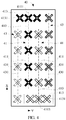
- FIG. 5 is a schematic structural diagram of a planar array antenna 50 according to a third embodiment of the present invention.
- the planar array antenna 50 includes two first radiation arrays 51 and two second radiation arrays 53 arranged along a first direction X, the two first radiation arrays 51 are arranged along a second direction Y at an interval, and the two second radiation arrays 53 are respectively arranged at two sides of the two first radiation arrays 51 along the second direction Y.
- Each first radiation array 51 includes four first radiation units 511 and one radiation unit pair 513, and the first radiation units 511 and the radiation unit pair 513 are disposed on an axis 510 of the first radiation array 51 along the first direction X.
- the radiation unit pair 513 in one of the two first radiation arrays 51 includes three second radiation units 5131, the three second radiation units 5131 are arranged along the second direction Y, and the three second radiation units 5131 are symmetric with respect to the axis 510 of the first radiation array 51.
- a specific arrangement manner is the same as that in the embodiment shown in FIG. 4 , and details are not described herein again.
- the radiation unit pair 513 in the other of the two first radiation arrays 51 includes six second radiation units 5131, and the six second radiation units 5131 are arranged in a matrix and are symmetric with respect to the axis 510 of the first radiation array 51.
- the second direction Y is perpendicular to the first direction X, and the second direction Y and the first direction X are in a same plane.
- the first direction X is a vertical direction
- the second direction Y is a horizontal direction.
- One of the two second radiation arrays 53 includes six first radiation units 531, and the first radiation units 531 are disposed on an axis 530 of the second radiation array 53.
- the other of the two second radiation arrays 53 includes five first radiation units 531, and the first radiation units 531 are disposed on an axis 530 of the second radiation array 53.
- Each first radiation unit 531 in the second radiation array 53 is horizontally aligned with one first radiation unit 511 or one second radiation unit 5131 in the first radiation array 51. It can be understood that, during actual application, the first radiation unit 531 in the second radiation array 53 and the first radiation unit 511 and the radiation unit pair 513 in the adjacent first radiation array 51 may be arranged in a staggered manner, to reduce a horizontal width of the planar array antenna 50.
- the radiation unit pair 513 includes six second radiation units 5131
- two of the six second radiation units 5131 are disposed on the axis 510 at an interval
- two of the other four second radiation units 5131 are respectively disposed horizontally on two sides of one second radiation unit 5131 on the axis 510
- the other two of the other four second radiation units 5131 are respectively disposed horizontally on two sides of the other second radiation unit 5131 on the axis 510
- each two of the other four second radiation units 5131 are vertically aligned and each two of the other four second radiation units 5131 are horizontally symmetric with respect to the axis 510.
- the even-numbered second radiation units 5131 may be arranged in a matrix.
- each first radiation array 51 includes a first end 5101 and a second end 5103 relative to each other, and the first ends 5101 of the first radiation arrays 51 are at a same side.
- the radiation unit pair 513 in one of the two first radiation arrays 51 is disposed at the first end 5101, and the radiation unit pair 513 in the other first radiation array 51 is disposed at the second end 5103, so that the radiation unit pairs 513 in the two adjacent first radiation arrays 51 are arranged in a staggered manner.
- both the first radiation unit 511 and the second radiation unit 5131 in each first radiation array 51 are dual-polarized radiation units working on a same frequency band, and all of the first radiation units 531 in each second radiation array 53 are dual-polarized radiation units working on a same frequency band.
- each first radiation array 51 may work on one frequency band, and each second radiation array 53 may work on one frequency band, to implement a multimode multiband array antenna.
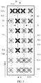
- FIG. 6 is a schematic structural diagram of a planar array antenna 60 according to a fourth embodiment of the present invention.
- the planar array antenna 60 includes two first radiation arrays 61 and two second radiation arrays 63 arranged along a first direction X, the two first radiation arrays 61 are arranged along a second direction Y at an interval, and the two second radiation arrays 63 are respectively arranged at two sides of the two first radiation arrays 61 along the second direction Y.
- Each first radiation array 61 includes four first radiation units 611 and two radiation unit pairs 613, the first radiation units 611 and the radiation unit pairs 613 are disposed on an axis 610 of the first radiation array 61 along the first direction X, the radiation unit pair 613 includes two second radiation units 6131, the two second radiation units 6131 are arranged along the second direction Y, and the two second radiation units 6131 are symmetric with respect to the axis 610 of the first radiation array 61.
- the first radiation units 611 and the radiation unit pairs 613 in the two first radiation arrays 61 are arranged on the second direction Y in a staggered manner.
- Each second radiation array 63 includes six first radiation units 631, and the first radiation units 631 are disposed on an axis 630 of the second radiation array 63.
- the first radiation unit 631 in each second radiation array 63 and the first radiation unit 611 and the radiation unit pair 613 in the adjacent first radiation array 61 are arranged along the second direction Y in a staggered manner.
- the second direction Y is perpendicular to the first direction X, and the second direction Y and the first direction X are in a same plane.
- the first direction X is a vertical direction
- the second direction Y is a horizontal direction.
- the first radiation units 611 and the radiation unit pairs 613 in the adjacent first radiation arrays 61 are arranged in a staggered manner, and the first radiation unit 631 in the second radiation array 63 adjacent to the first radiation array 61 and the first radiation unit 611 and the radiation unit pair 613 are arranged in a staggered manner, so that a distance between the adjacent first radiation arrays 61 and a distance between the first radiation array 61 and the adjacent second radiation array 63 can be effectively reduced. Therefore, the planar array antenna 60 has a compact horizontal width dimension.
- first radiation units 611 and the radiation unit pairs 613 in the adjacent first radiation arrays 61 are arranged in a staggered manner, and the first radiation unit 631 in the second radiation array 63 adjacent to the first radiation array 61 and the first radiation unit 611 and the radiation unit pair 613 are arranged in a staggered manner, interference between the first radiation units 611 and the radiation unit pairs 613 in the adjacent first radiation arrays 61 can be reduced, and interference between the first radiation units 611 and the radiation unit pairs 613 in the first radiation arrays 61 and the first radiation units 631 in the second radiation array 63 is reduced, so that radiation performance of the planar array antenna 60 is improved.
- an embodiment of the present invention further provides a communications device, including a planar array antenna, and the planar array antenna is configured to receive and send and transmit a wireless communication signal.
- the communications device may be a base station, and the planar array antenna may be the planar array antenna described in any embodiment shown in FIG. 3 to FIG. 6 . Specifically, refer to the related descriptions in the embodiments in FIG. 3 to FIG. 6 , and details are not described herein again.
- the radiation unit pair is disposed in the first radiation array, and the second radiation units included in the radiation unit pair are symmetrical with respect to the axis of the first radiation array. Therefore, all of the radiation units in the first radiation array are symmetric with respect to the axis, so that the planar array antenna has a relatively small horizontal beam width, a symmetric horizontal directivity pattern, and a relatively high gain.
- the first radiation array is disposed in the planar array antenna, so that the planar array antenna has a compact horizontal width dimension, and design and mounting of a multimode multiband array antenna can be implemented in limited space.
Landscapes
- Engineering & Computer Science (AREA)
- Computer Networks & Wireless Communication (AREA)
- Variable-Direction Aerials And Aerial Arrays (AREA)
Claims (3)
- Antenne réseau plan (30) comprenant :au moins deux premiers réseaux de rayonnement adjacents (31) disposés dans une première direction, dans laquelle chaque premier réseau de rayonnement (31) comprend au moins une première unité de rayonnement (311) et au moins une paire d'unités de rayonnement (313), la première unité de rayonnement (311) et la paire d'unités de rayonnement (313) sont disposées sur un axe (310) du premier réseau de rayonnement (31), la paire d'unités de rayonnement (313) comprend au moins deux secondes unités de rayonnement (3131), et les au moins deux secondes unités de rayonnement (3131) sont symétriques par rapport à l'axe (310) du premier réseau de rayonnement (31);dans lequel les premières unités de rayonnement (311) et les paires d'unités de rayonnement (313) dans deux premiers réseaux de rayonnement adjacents (31) sont disposées en quinconce ; etdans lequel chaque premier réseau de rayonnement (31) comprend une première extrémité et une seconde extrémité relatives l'une à l'autre, les premières extrémités des premiers réseaux de rayonnement (31) se trouvent du même côté, la paire d'unités de rayonnement (313) dans l'un des deux premiers réseaux de rayonnement adjacents (31) est disposée à la première extrémité de l'un des premiers réseaux de rayonnement (31), et la paire d'unités de rayonnement (313) dans l'autre des deux premiers réseaux de rayonnement adjacents (31) est disposée à la seconde extrémité de l'autre des premiers réseaux de rayonnement (31).
- Antenne réseau plan (30) selon la revendication 1, dans laquelle la première unité de rayonnement (311) et les secondes unités de rayonnement (3131) dans chaque premier réseau de rayonnement (31) sont toutes des unités de rayonnement à double polarisation conçues pour fonctionner sur une même bande de fréquences.
- Dispositif de communication, le dispositif de communication comprenant l'antenne réseau plan (30) selon l'une quelconque des revendications 1 et 2.
Applications Claiming Priority (2)
| Application Number | Priority Date | Filing Date | Title |
|---|---|---|---|
| CN201521061945.0U CN205319307U (zh) | 2015-12-16 | 2015-12-16 | 平面阵列天线及通信设备 |
| PCT/CN2016/108950 WO2017101722A1 (fr) | 2015-12-16 | 2016-12-07 | Antenne réseau plan et dispositif de communication |
Publications (3)
| Publication Number | Publication Date |
|---|---|
| EP3379648A1 EP3379648A1 (fr) | 2018-09-26 |
| EP3379648A4 EP3379648A4 (fr) | 2018-12-05 |
| EP3379648B1 true EP3379648B1 (fr) | 2021-04-07 |
Family
ID=56186540
Family Applications (1)
| Application Number | Title | Priority Date | Filing Date |
|---|---|---|---|
| EP16874779.8A Active EP3379648B1 (fr) | 2015-12-16 | 2016-12-07 | Antenne réseau plan et dispositif de communication |
Country Status (5)
| Country | Link |
|---|---|
| US (1) | US10957991B2 (fr) |
| EP (1) | EP3379648B1 (fr) |
| CN (1) | CN205319307U (fr) |
| BR (1) | BR112018012278B1 (fr) |
| WO (1) | WO2017101722A1 (fr) |
Families Citing this family (9)
| Publication number | Priority date | Publication date | Assignee | Title |
|---|---|---|---|---|
| CN205319307U (zh) * | 2015-12-16 | 2016-06-15 | 华为技术有限公司 | 平面阵列天线及通信设备 |
| CN110121841A (zh) * | 2017-01-25 | 2019-08-13 | 华为技术有限公司 | 一种波束生成方法及基站 |
| CN110071373B (zh) * | 2018-03-12 | 2023-03-14 | 京信通信技术(广州)有限公司 | 多制式融合的天线 |
| CN111817026A (zh) | 2019-04-10 | 2020-10-23 | 康普技术有限责任公司 | 具有带有频率选择性共享辐射元件的阵列的基站天线 |
| US11056773B2 (en) * | 2019-06-28 | 2021-07-06 | Commscope Technologies Llc | Twin-beam base station antennas having thinned arrays with triangular sub-arrays |
| GB2597269A (en) * | 2020-07-17 | 2022-01-26 | Nokia Shanghai Bell Co Ltd | Antenna apparatus |
| WO2022262956A1 (fr) * | 2021-06-15 | 2022-12-22 | Telefonaktiebolaget Lm Ericsson (Publ) | Systèmes d'antennes avancés à lobes secondaires réduits |
| CN116404399A (zh) * | 2021-12-27 | 2023-07-07 | 普罗斯通信技术(苏州)有限公司 | 辐射阵列组及窄波束天线 |
| CN114447585B (zh) * | 2022-01-29 | 2024-03-19 | 京东方科技集团股份有限公司 | 多波束天线及其制备方法、通信装置 |
Family Cites Families (11)
| Publication number | Priority date | Publication date | Assignee | Title |
|---|---|---|---|---|
| DE19823749C2 (de) * | 1998-05-27 | 2002-07-11 | Kathrein Werke Kg | Dualpolarisierte Mehrbereichsantenne |
| DE10256960B3 (de) * | 2002-12-05 | 2004-07-29 | Kathrein-Werke Kg | Zweidimensionales Antennen-Array |
| US8508427B2 (en) * | 2008-01-28 | 2013-08-13 | P-Wave Holdings, Llc | Tri-column adjustable azimuth beam width antenna for wireless network |
| EP2359438B1 (fr) * | 2008-11-20 | 2019-07-17 | CommScope Technologies LLC | Antenne sectorielle double faisceau et réseau associé |
| BR112014017345A2 (pt) | 2012-01-13 | 2017-06-27 | Comba Telecom System China Ltd | sistema de controle de antena e antena de multifrequencia partilhada |
| US9615765B2 (en) * | 2012-09-04 | 2017-04-11 | Vayyar Imaging Ltd. | Wideband radar with heterogeneous antenna arrays |
| CN103311651B (zh) * | 2013-05-17 | 2016-08-03 | 广东通宇通讯股份有限公司 | 一种超宽带多频双极化天线 |
| US10069213B2 (en) * | 2014-01-31 | 2018-09-04 | Quintel Technology Limited | Antenna system with beamwidth control |
| CN103956587B (zh) | 2014-04-21 | 2016-09-28 | 广州杰赛科技股份有限公司 | 双极化阵列天线单元及低剖面高隔离度mimo天线 |
| CN104795635B (zh) * | 2015-04-03 | 2017-11-28 | 京信通信技术(广州)有限公司 | 多频阵列天线 |
| CN205319307U (zh) * | 2015-12-16 | 2016-06-15 | 华为技术有限公司 | 平面阵列天线及通信设备 |
-
2015
- 2015-12-16 CN CN201521061945.0U patent/CN205319307U/zh active Active
-
2016
- 2016-12-07 WO PCT/CN2016/108950 patent/WO2017101722A1/fr active Application Filing
- 2016-12-07 EP EP16874779.8A patent/EP3379648B1/fr active Active
- 2016-12-07 BR BR112018012278-5A patent/BR112018012278B1/pt active IP Right Grant
-
2018
- 2018-06-15 US US16/009,689 patent/US10957991B2/en active Active
Non-Patent Citations (1)
| Title |
|---|
| None * |
Also Published As
| Publication number | Publication date |
|---|---|
| BR112018012278A2 (pt) | 2018-11-27 |
| BR112018012278B1 (pt) | 2022-11-01 |
| US10957991B2 (en) | 2021-03-23 |
| EP3379648A1 (fr) | 2018-09-26 |
| WO2017101722A1 (fr) | 2017-06-22 |
| CN205319307U (zh) | 2016-06-15 |
| US20180294578A1 (en) | 2018-10-11 |
| EP3379648A4 (fr) | 2018-12-05 |
Similar Documents
| Publication | Publication Date | Title |
|---|---|---|
| EP3379648B1 (fr) | Antenne réseau plan et dispositif de communication | |
| EP2846400B1 (fr) | Réseau d'antennes, dispositif antenne et station de base | |
| EP3120416B1 (fr) | Réseau d'antennes compact utilisant la rotation virtuelle de vecteurs de rayonnement | |
| EP2959710B1 (fr) | Antenne multiréseau | |
| EP3089270B1 (fr) | Antenne à réseau multifréquence | |
| EP3686990B1 (fr) | Antenne sectorielle double faisceau et réseau associé | |
| EP2741369B1 (fr) | Antenne multimode et station de base | |
| CN107785665B (zh) | 一种混合结构双频双波束三列相控阵天线 | |
| CN105634627B (zh) | 一种天线阵耦合校准网络装置及校准方法 | |
| EP3510666B1 (fr) | Réseau d'antennes et agencement comprenant un réseau d'antennes et un noeud de réseau | |
| CN107359424B (zh) | 一种阵列天线 | |
| CN106252903B (zh) | 一种双频两波束天线阵列及双频两波束天线 | |
| JP2017539134A (ja) | スマートアンテナ装置 | |
| CN103367932A (zh) | 一种双波束天线 | |
| EP2564469B1 (fr) | Antenne réseau plane avec largeur de faisceau reduite | |
| CN107968253B (zh) | Mimo天线系统、天线阵列及其低频辐射单元 | |
| CN110994203B (zh) | 一种宽频混合多波束阵列天线 | |
| US11075467B2 (en) | Two-dimensional antenna and network device | |
| JP2019087942A (ja) | 周波数共用アレイアンテナ | |
| US11646502B2 (en) | Multi-band base station antenna | |
| JP2014045278A (ja) | 周波数共用指向性アンテナ | |
| CN108923116B (zh) | 一种高频辐射单元及多频阵列天线 | |
| WO2023231752A1 (fr) | Antenne et station de base | |
| CN108767498B (zh) | 一种可控制波束宽度的多系统基站天线 | |
| CN115441183A (zh) | 天线和通信设备 |
Legal Events
| Date | Code | Title | Description |
|---|---|---|---|
| STAA | Information on the status of an ep patent application or granted ep patent |
Free format text: STATUS: THE INTERNATIONAL PUBLICATION HAS BEEN MADE |
|
| PUAI | Public reference made under article 153(3) epc to a published international application that has entered the european phase |
Free format text: ORIGINAL CODE: 0009012 |
|
| STAA | Information on the status of an ep patent application or granted ep patent |
Free format text: STATUS: REQUEST FOR EXAMINATION WAS MADE |
|
| 17P | Request for examination filed |
Effective date: 20180620 |
|
| AK | Designated contracting states |
Kind code of ref document: A1 Designated state(s): AL AT BE BG CH CY CZ DE DK EE ES FI FR GB GR HR HU IE IS IT LI LT LU LV MC MK MT NL NO PL PT RO RS SE SI SK SM TR |
|
| AX | Request for extension of the european patent |
Extension state: BA ME |
|
| REG | Reference to a national code |
Ref country code: DE Ref legal event code: R079 Ref document number: 602016055869 Country of ref document: DE Free format text: PREVIOUS MAIN CLASS: H01Q0001360000 Ipc: H01Q0021240000 |
|
| A4 | Supplementary search report drawn up and despatched |
Effective date: 20181030 |
|
| RIC1 | Information provided on ipc code assigned before grant |
Ipc: H01Q 1/24 20060101ALI20181024BHEP Ipc: H01Q 21/24 20060101AFI20181024BHEP |
|
| DAV | Request for validation of the european patent (deleted) | ||
| DAX | Request for extension of the european patent (deleted) | ||
| GRAP | Despatch of communication of intention to grant a patent |
Free format text: ORIGINAL CODE: EPIDOSNIGR1 |
|
| STAA | Information on the status of an ep patent application or granted ep patent |
Free format text: STATUS: GRANT OF PATENT IS INTENDED |
|
| INTG | Intention to grant announced |
Effective date: 20201124 |
|
| GRAS | Grant fee paid |
Free format text: ORIGINAL CODE: EPIDOSNIGR3 |
|
| GRAA | (expected) grant |
Free format text: ORIGINAL CODE: 0009210 |
|
| STAA | Information on the status of an ep patent application or granted ep patent |
Free format text: STATUS: THE PATENT HAS BEEN GRANTED |
|
| AK | Designated contracting states |
Kind code of ref document: B1 Designated state(s): AL AT BE BG CH CY CZ DE DK EE ES FI FR GB GR HR HU IE IS IT LI LT LU LV MC MK MT NL NO PL PT RO RS SE SI SK SM TR |
|
| REG | Reference to a national code |
Ref country code: GB Ref legal event code: FG4D |
|
| REG | Reference to a national code |
Ref country code: CH Ref legal event code: EP Ref country code: AT Ref legal event code: REF Ref document number: 1380880 Country of ref document: AT Kind code of ref document: T Effective date: 20210415 |
|
| REG | Reference to a national code |
Ref country code: DE Ref legal event code: R096 Ref document number: 602016055869 Country of ref document: DE |
|
| REG | Reference to a national code |
Ref country code: IE Ref legal event code: FG4D |
|
| REG | Reference to a national code |
Ref country code: NL Ref legal event code: FP |
|
| REG | Reference to a national code |
Ref country code: LT Ref legal event code: MG9D |
|
| REG | Reference to a national code |
Ref country code: AT Ref legal event code: MK05 Ref document number: 1380880 Country of ref document: AT Kind code of ref document: T Effective date: 20210407 |
|
| PG25 | Lapsed in a contracting state [announced via postgrant information from national office to epo] |
Ref country code: BG Free format text: LAPSE BECAUSE OF FAILURE TO SUBMIT A TRANSLATION OF THE DESCRIPTION OR TO PAY THE FEE WITHIN THE PRESCRIBED TIME-LIMIT Effective date: 20210707 Ref country code: AT Free format text: LAPSE BECAUSE OF FAILURE TO SUBMIT A TRANSLATION OF THE DESCRIPTION OR TO PAY THE FEE WITHIN THE PRESCRIBED TIME-LIMIT Effective date: 20210407 Ref country code: HR Free format text: LAPSE BECAUSE OF FAILURE TO SUBMIT A TRANSLATION OF THE DESCRIPTION OR TO PAY THE FEE WITHIN THE PRESCRIBED TIME-LIMIT Effective date: 20210407 Ref country code: FI Free format text: LAPSE BECAUSE OF FAILURE TO SUBMIT A TRANSLATION OF THE DESCRIPTION OR TO PAY THE FEE WITHIN THE PRESCRIBED TIME-LIMIT Effective date: 20210407 Ref country code: LT Free format text: LAPSE BECAUSE OF FAILURE TO SUBMIT A TRANSLATION OF THE DESCRIPTION OR TO PAY THE FEE WITHIN THE PRESCRIBED TIME-LIMIT Effective date: 20210407 |
|
| PG25 | Lapsed in a contracting state [announced via postgrant information from national office to epo] |
Ref country code: RS Free format text: LAPSE BECAUSE OF FAILURE TO SUBMIT A TRANSLATION OF THE DESCRIPTION OR TO PAY THE FEE WITHIN THE PRESCRIBED TIME-LIMIT Effective date: 20210407 Ref country code: SE Free format text: LAPSE BECAUSE OF FAILURE TO SUBMIT A TRANSLATION OF THE DESCRIPTION OR TO PAY THE FEE WITHIN THE PRESCRIBED TIME-LIMIT Effective date: 20210407 Ref country code: NO Free format text: LAPSE BECAUSE OF FAILURE TO SUBMIT A TRANSLATION OF THE DESCRIPTION OR TO PAY THE FEE WITHIN THE PRESCRIBED TIME-LIMIT Effective date: 20210707 Ref country code: PL Free format text: LAPSE BECAUSE OF FAILURE TO SUBMIT A TRANSLATION OF THE DESCRIPTION OR TO PAY THE FEE WITHIN THE PRESCRIBED TIME-LIMIT Effective date: 20210407 Ref country code: PT Free format text: LAPSE BECAUSE OF FAILURE TO SUBMIT A TRANSLATION OF THE DESCRIPTION OR TO PAY THE FEE WITHIN THE PRESCRIBED TIME-LIMIT Effective date: 20210809 Ref country code: LV Free format text: LAPSE BECAUSE OF FAILURE TO SUBMIT A TRANSLATION OF THE DESCRIPTION OR TO PAY THE FEE WITHIN THE PRESCRIBED TIME-LIMIT Effective date: 20210407 Ref country code: GR Free format text: LAPSE BECAUSE OF FAILURE TO SUBMIT A TRANSLATION OF THE DESCRIPTION OR TO PAY THE FEE WITHIN THE PRESCRIBED TIME-LIMIT Effective date: 20210708 Ref country code: IS Free format text: LAPSE BECAUSE OF FAILURE TO SUBMIT A TRANSLATION OF THE DESCRIPTION OR TO PAY THE FEE WITHIN THE PRESCRIBED TIME-LIMIT Effective date: 20210807 |
|
| REG | Reference to a national code |
Ref country code: DE Ref legal event code: R097 Ref document number: 602016055869 Country of ref document: DE |
|
| PG25 | Lapsed in a contracting state [announced via postgrant information from national office to epo] |
Ref country code: ES Free format text: LAPSE BECAUSE OF FAILURE TO SUBMIT A TRANSLATION OF THE DESCRIPTION OR TO PAY THE FEE WITHIN THE PRESCRIBED TIME-LIMIT Effective date: 20210407 Ref country code: RO Free format text: LAPSE BECAUSE OF FAILURE TO SUBMIT A TRANSLATION OF THE DESCRIPTION OR TO PAY THE FEE WITHIN THE PRESCRIBED TIME-LIMIT Effective date: 20210407 Ref country code: DK Free format text: LAPSE BECAUSE OF FAILURE TO SUBMIT A TRANSLATION OF THE DESCRIPTION OR TO PAY THE FEE WITHIN THE PRESCRIBED TIME-LIMIT Effective date: 20210407 Ref country code: CZ Free format text: LAPSE BECAUSE OF FAILURE TO SUBMIT A TRANSLATION OF THE DESCRIPTION OR TO PAY THE FEE WITHIN THE PRESCRIBED TIME-LIMIT Effective date: 20210407 Ref country code: EE Free format text: LAPSE BECAUSE OF FAILURE TO SUBMIT A TRANSLATION OF THE DESCRIPTION OR TO PAY THE FEE WITHIN THE PRESCRIBED TIME-LIMIT Effective date: 20210407 Ref country code: SM Free format text: LAPSE BECAUSE OF FAILURE TO SUBMIT A TRANSLATION OF THE DESCRIPTION OR TO PAY THE FEE WITHIN THE PRESCRIBED TIME-LIMIT Effective date: 20210407 Ref country code: SK Free format text: LAPSE BECAUSE OF FAILURE TO SUBMIT A TRANSLATION OF THE DESCRIPTION OR TO PAY THE FEE WITHIN THE PRESCRIBED TIME-LIMIT Effective date: 20210407 |
|
| PLBE | No opposition filed within time limit |
Free format text: ORIGINAL CODE: 0009261 |
|
| STAA | Information on the status of an ep patent application or granted ep patent |
Free format text: STATUS: NO OPPOSITION FILED WITHIN TIME LIMIT |
|
| 26N | No opposition filed |
Effective date: 20220110 |
|
| PG25 | Lapsed in a contracting state [announced via postgrant information from national office to epo] |
Ref country code: IS Free format text: LAPSE BECAUSE OF FAILURE TO SUBMIT A TRANSLATION OF THE DESCRIPTION OR TO PAY THE FEE WITHIN THE PRESCRIBED TIME-LIMIT Effective date: 20210807 Ref country code: AL Free format text: LAPSE BECAUSE OF FAILURE TO SUBMIT A TRANSLATION OF THE DESCRIPTION OR TO PAY THE FEE WITHIN THE PRESCRIBED TIME-LIMIT Effective date: 20210407 |
|
| PG25 | Lapsed in a contracting state [announced via postgrant information from national office to epo] |
Ref country code: MC Free format text: LAPSE BECAUSE OF FAILURE TO SUBMIT A TRANSLATION OF THE DESCRIPTION OR TO PAY THE FEE WITHIN THE PRESCRIBED TIME-LIMIT Effective date: 20210407 Ref country code: IT Free format text: LAPSE BECAUSE OF FAILURE TO SUBMIT A TRANSLATION OF THE DESCRIPTION OR TO PAY THE FEE WITHIN THE PRESCRIBED TIME-LIMIT Effective date: 20210407 |
|
| REG | Reference to a national code |
Ref country code: CH Ref legal event code: PL |
|
| REG | Reference to a national code |
Ref country code: BE Ref legal event code: MM Effective date: 20211231 |
|
| PG25 | Lapsed in a contracting state [announced via postgrant information from national office to epo] |
Ref country code: LU Free format text: LAPSE BECAUSE OF NON-PAYMENT OF DUE FEES Effective date: 20211207 Ref country code: IE Free format text: LAPSE BECAUSE OF NON-PAYMENT OF DUE FEES Effective date: 20211207 |
|
| PG25 | Lapsed in a contracting state [announced via postgrant information from national office to epo] |
Ref country code: FR Free format text: LAPSE BECAUSE OF NON-PAYMENT OF DUE FEES Effective date: 20211231 Ref country code: BE Free format text: LAPSE BECAUSE OF NON-PAYMENT OF DUE FEES Effective date: 20211231 |
|
| PG25 | Lapsed in a contracting state [announced via postgrant information from national office to epo] |
Ref country code: LI Free format text: LAPSE BECAUSE OF NON-PAYMENT OF DUE FEES Effective date: 20211231 Ref country code: CH Free format text: LAPSE BECAUSE OF NON-PAYMENT OF DUE FEES Effective date: 20211231 |
|
| PG25 | Lapsed in a contracting state [announced via postgrant information from national office to epo] |
Ref country code: HU Free format text: LAPSE BECAUSE OF FAILURE TO SUBMIT A TRANSLATION OF THE DESCRIPTION OR TO PAY THE FEE WITHIN THE PRESCRIBED TIME-LIMIT; INVALID AB INITIO Effective date: 20161207 |
|
| PG25 | Lapsed in a contracting state [announced via postgrant information from national office to epo] |
Ref country code: CY Free format text: LAPSE BECAUSE OF FAILURE TO SUBMIT A TRANSLATION OF THE DESCRIPTION OR TO PAY THE FEE WITHIN THE PRESCRIBED TIME-LIMIT Effective date: 20210407 |
|
| PGFP | Annual fee paid to national office [announced via postgrant information from national office to epo] |
Ref country code: NL Payment date: 20231116 Year of fee payment: 8 |
|
| PGFP | Annual fee paid to national office [announced via postgrant information from national office to epo] |
Ref country code: GB Payment date: 20231102 Year of fee payment: 8 |
|
| PGFP | Annual fee paid to national office [announced via postgrant information from national office to epo] |
Ref country code: DE Payment date: 20231031 Year of fee payment: 8 |
|
| PG25 | Lapsed in a contracting state [announced via postgrant information from national office to epo] |
Ref country code: MK Free format text: LAPSE BECAUSE OF FAILURE TO SUBMIT A TRANSLATION OF THE DESCRIPTION OR TO PAY THE FEE WITHIN THE PRESCRIBED TIME-LIMIT Effective date: 20210407 |
|
| PG25 | Lapsed in a contracting state [announced via postgrant information from national office to epo] |
Ref country code: TR Free format text: LAPSE BECAUSE OF FAILURE TO SUBMIT A TRANSLATION OF THE DESCRIPTION OR TO PAY THE FEE WITHIN THE PRESCRIBED TIME-LIMIT Effective date: 20210407 |