EP3379600A1 - Secondary battery, battery pack, and vehicle - Google Patents
Secondary battery, battery pack, and vehicle Download PDFInfo
- Publication number
- EP3379600A1 EP3379600A1 EP17190100.2A EP17190100A EP3379600A1 EP 3379600 A1 EP3379600 A1 EP 3379600A1 EP 17190100 A EP17190100 A EP 17190100A EP 3379600 A1 EP3379600 A1 EP 3379600A1
- Authority
- EP
- European Patent Office
- Prior art keywords
- electrode
- tabs
- negative electrode
- electrode tabs
- positive
- Prior art date
- Legal status (The legal status is an assumption and is not a legal conclusion. Google has not performed a legal analysis and makes no representation as to the accuracy of the status listed.)
- Granted
Links
- 230000001681 protective effect Effects 0.000 claims description 23
- 238000009826 distribution Methods 0.000 claims description 19
- 230000001172 regenerating effect Effects 0.000 claims description 11
- 230000007246 mechanism Effects 0.000 claims description 5
- 238000013459 approach Methods 0.000 abstract description 98
- 239000002245 particle Substances 0.000 description 30
- XAGFODPZIPBFFR-UHFFFAOYSA-N aluminium Chemical compound [Al] XAGFODPZIPBFFR-UHFFFAOYSA-N 0.000 description 27
- 229910052782 aluminium Inorganic materials 0.000 description 26
- 239000006258 conductive agent Substances 0.000 description 26
- 239000011230 binding agent Substances 0.000 description 23
- 229910045601 alloy Inorganic materials 0.000 description 22
- 239000000956 alloy Substances 0.000 description 22
- 239000011888 foil Substances 0.000 description 22
- -1 Li2+xTi3O7 Chemical compound 0.000 description 21
- 239000003792 electrolyte Substances 0.000 description 21
- 239000007773 negative electrode material Substances 0.000 description 20
- 239000002131 composite material Substances 0.000 description 19
- 229910000838 Al alloy Inorganic materials 0.000 description 18
- 239000011255 nonaqueous electrolyte Substances 0.000 description 15
- XEEYBQQBJWHFJM-UHFFFAOYSA-N Iron Chemical compound [Fe] XEEYBQQBJWHFJM-UHFFFAOYSA-N 0.000 description 12
- 239000011149 active material Substances 0.000 description 11
- PXHVJJICTQNCMI-UHFFFAOYSA-N Nickel Chemical compound [Ni] PXHVJJICTQNCMI-UHFFFAOYSA-N 0.000 description 10
- 239000002033 PVDF binder Substances 0.000 description 10
- 230000000052 comparative effect Effects 0.000 description 10
- 229920002981 polyvinylidene fluoride Polymers 0.000 description 10
- OKTJSMMVPCPJKN-UHFFFAOYSA-N Carbon Chemical compound [C] OKTJSMMVPCPJKN-UHFFFAOYSA-N 0.000 description 9
- 230000000694 effects Effects 0.000 description 9
- 239000011163 secondary particle Substances 0.000 description 9
- 239000004698 Polyethylene Substances 0.000 description 8
- 238000004891 communication Methods 0.000 description 8
- 229920000573 polyethylene Polymers 0.000 description 8
- 239000007774 positive electrode material Substances 0.000 description 8
- WABPQHHGFIMREM-NJFSPNSNSA-N lead-209 Chemical compound [209Pb] WABPQHHGFIMREM-NJFSPNSNSA-N 0.000 description 7
- WEVYAHXRMPXWCK-UHFFFAOYSA-N Acetonitrile Chemical compound CC#N WEVYAHXRMPXWCK-UHFFFAOYSA-N 0.000 description 6
- 229910018182 Al—Cu Inorganic materials 0.000 description 6
- OIFBSDVPJOWBCH-UHFFFAOYSA-N Diethyl carbonate Chemical compound CCOC(=O)OCC OIFBSDVPJOWBCH-UHFFFAOYSA-N 0.000 description 6
- FYYHWMGAXLPEAU-UHFFFAOYSA-N Magnesium Chemical compound [Mg] FYYHWMGAXLPEAU-UHFFFAOYSA-N 0.000 description 6
- 239000004743 Polypropylene Substances 0.000 description 6
- XUIMIQQOPSSXEZ-UHFFFAOYSA-N Silicon Chemical compound [Si] XUIMIQQOPSSXEZ-UHFFFAOYSA-N 0.000 description 6
- GWEVSGVZZGPLCZ-UHFFFAOYSA-N Titan oxide Chemical compound O=[Ti]=O GWEVSGVZZGPLCZ-UHFFFAOYSA-N 0.000 description 6
- HCHKCACWOHOZIP-UHFFFAOYSA-N Zinc Chemical compound [Zn] HCHKCACWOHOZIP-UHFFFAOYSA-N 0.000 description 6
- 239000003575 carbonaceous material Substances 0.000 description 6
- 238000001514 detection method Methods 0.000 description 6
- 229910052742 iron Inorganic materials 0.000 description 6
- 239000005001 laminate film Substances 0.000 description 6
- 229910052749 magnesium Inorganic materials 0.000 description 6
- 239000011777 magnesium Substances 0.000 description 6
- 238000012544 monitoring process Methods 0.000 description 6
- 239000003960 organic solvent Substances 0.000 description 6
- 229920001155 polypropylene Polymers 0.000 description 6
- RUOJZAUFBMNUDX-UHFFFAOYSA-N propylene carbonate Chemical compound CC1COC(=O)O1 RUOJZAUFBMNUDX-UHFFFAOYSA-N 0.000 description 6
- 229910052710 silicon Inorganic materials 0.000 description 6
- 239000010703 silicon Substances 0.000 description 6
- 239000010936 titanium Substances 0.000 description 6
- 229910052725 zinc Inorganic materials 0.000 description 6
- 239000011701 zinc Substances 0.000 description 6
- VYZAMTAEIAYCRO-UHFFFAOYSA-N Chromium Chemical compound [Cr] VYZAMTAEIAYCRO-UHFFFAOYSA-N 0.000 description 5
- HBBGRARXTFLTSG-UHFFFAOYSA-N Lithium ion Chemical compound [Li+] HBBGRARXTFLTSG-UHFFFAOYSA-N 0.000 description 5
- RTAQQCXQSZGOHL-UHFFFAOYSA-N Titanium Chemical compound [Ti] RTAQQCXQSZGOHL-UHFFFAOYSA-N 0.000 description 5
- FDLZQPXZHIFURF-UHFFFAOYSA-N [O-2].[Ti+4].[Li+] Chemical compound [O-2].[Ti+4].[Li+] FDLZQPXZHIFURF-UHFFFAOYSA-N 0.000 description 5
- 229910052804 chromium Inorganic materials 0.000 description 5
- 239000011651 chromium Substances 0.000 description 5
- 229910001416 lithium ion Inorganic materials 0.000 description 5
- 238000000034 method Methods 0.000 description 5
- 229910052759 nickel Inorganic materials 0.000 description 5
- 238000003825 pressing Methods 0.000 description 5
- 239000011164 primary particle Substances 0.000 description 5
- 150000003839 salts Chemical class 0.000 description 5
- 229910052719 titanium Inorganic materials 0.000 description 5
- 229910052723 transition metal Inorganic materials 0.000 description 5
- 150000003624 transition metals Chemical class 0.000 description 5
- DHKHKXVYLBGOIT-UHFFFAOYSA-N 1,1-Diethoxyethane Chemical compound CCOC(C)OCC DHKHKXVYLBGOIT-UHFFFAOYSA-N 0.000 description 4
- KMTRUDSVKNLOMY-UHFFFAOYSA-N Ethylene carbonate Chemical compound O=C1OCCO1 KMTRUDSVKNLOMY-UHFFFAOYSA-N 0.000 description 4
- SECXISVLQFMRJM-UHFFFAOYSA-N N-Methylpyrrolidone Chemical compound CN1CCCC1=O SECXISVLQFMRJM-UHFFFAOYSA-N 0.000 description 4
- WYURNTSHIVDZCO-UHFFFAOYSA-N Tetrahydrofuran Chemical compound C1CCOC1 WYURNTSHIVDZCO-UHFFFAOYSA-N 0.000 description 4
- SOXUFMZTHZXOGC-UHFFFAOYSA-N [Li].[Mn].[Co].[Ni] Chemical compound [Li].[Mn].[Co].[Ni] SOXUFMZTHZXOGC-UHFFFAOYSA-N 0.000 description 4
- 238000001035 drying Methods 0.000 description 4
- 239000007788 liquid Substances 0.000 description 4
- WPBNNNQJVZRUHP-UHFFFAOYSA-L manganese(2+);methyl n-[[2-(methoxycarbonylcarbamothioylamino)phenyl]carbamothioyl]carbamate;n-[2-(sulfidocarbothioylamino)ethyl]carbamodithioate Chemical compound [Mn+2].[S-]C(=S)NCCNC([S-])=S.COC(=O)NC(=S)NC1=CC=CC=C1NC(=S)NC(=O)OC WPBNNNQJVZRUHP-UHFFFAOYSA-L 0.000 description 4
- 239000000463 material Substances 0.000 description 4
- 239000012046 mixed solvent Substances 0.000 description 4
- 229920000139 polyethylene terephthalate Polymers 0.000 description 4
- 239000005020 polyethylene terephthalate Substances 0.000 description 4
- 229920001343 polytetrafluoroethylene Polymers 0.000 description 4
- 239000004810 polytetrafluoroethylene Substances 0.000 description 4
- 239000002243 precursor Substances 0.000 description 4
- 229920005989 resin Polymers 0.000 description 4
- 239000011347 resin Substances 0.000 description 4
- 239000002002 slurry Substances 0.000 description 4
- 239000002904 solvent Substances 0.000 description 4
- 229910052596 spinel Inorganic materials 0.000 description 4
- 239000011029 spinel Substances 0.000 description 4
- 238000003756 stirring Methods 0.000 description 4
- 239000000725 suspension Substances 0.000 description 4
- OGIDPMRJRNCKJF-UHFFFAOYSA-N titanium oxide Inorganic materials [Ti]=O OGIDPMRJRNCKJF-UHFFFAOYSA-N 0.000 description 4
- 229910018084 Al-Fe Inorganic materials 0.000 description 3
- 229910018134 Al-Mg Inorganic materials 0.000 description 3
- 229910018131 Al-Mn Inorganic materials 0.000 description 3
- 229910018192 Al—Fe Inorganic materials 0.000 description 3
- 229910018467 Al—Mg Inorganic materials 0.000 description 3
- 229910018461 Al—Mn Inorganic materials 0.000 description 3
- RYGMFSIKBFXOCR-UHFFFAOYSA-N Copper Chemical compound [Cu] RYGMFSIKBFXOCR-UHFFFAOYSA-N 0.000 description 3
- NXPZICSHDHGMGT-UHFFFAOYSA-N [Co].[Mn].[Li] Chemical compound [Co].[Mn].[Li] NXPZICSHDHGMGT-UHFFFAOYSA-N 0.000 description 3
- 239000006230 acetylene black Substances 0.000 description 3
- 239000002390 adhesive tape Substances 0.000 description 3
- 238000005054 agglomeration Methods 0.000 description 3
- 230000002776 aggregation Effects 0.000 description 3
- 230000007797 corrosion Effects 0.000 description 3
- 238000005260 corrosion Methods 0.000 description 3
- 230000006866 deterioration Effects 0.000 description 3
- 238000010586 diagram Methods 0.000 description 3
- 229920001971 elastomer Polymers 0.000 description 3
- 229910002804 graphite Inorganic materials 0.000 description 3
- 239000010439 graphite Substances 0.000 description 3
- 238000010438 heat treatment Methods 0.000 description 3
- 239000000203 mixture Substances 0.000 description 3
- 239000010450 olivine Substances 0.000 description 3
- 229910052609 olivine Inorganic materials 0.000 description 3
- 230000008569 process Effects 0.000 description 3
- 230000009467 reduction Effects 0.000 description 3
- 239000005060 rubber Substances 0.000 description 3
- WNXJIVFYUVYPPR-UHFFFAOYSA-N 1,3-dioxolane Chemical compound C1COCO1 WNXJIVFYUVYPPR-UHFFFAOYSA-N 0.000 description 2
- GEWWCWZGHNIUBW-UHFFFAOYSA-N 1-(4-nitrophenyl)propan-2-one Chemical compound CC(=O)CC1=CC=C([N+]([O-])=O)C=C1 GEWWCWZGHNIUBW-UHFFFAOYSA-N 0.000 description 2
- VZSRBBMJRBPUNF-UHFFFAOYSA-N 2-(2,3-dihydro-1H-inden-2-ylamino)-N-[3-oxo-3-(2,4,6,7-tetrahydrotriazolo[4,5-c]pyridin-5-yl)propyl]pyrimidine-5-carboxamide Chemical compound C1C(CC2=CC=CC=C12)NC1=NC=C(C=N1)C(=O)NCCC(N1CC2=C(CC1)NN=N2)=O VZSRBBMJRBPUNF-UHFFFAOYSA-N 0.000 description 2
- JWUJQDFVADABEY-UHFFFAOYSA-N 2-methyltetrahydrofuran Chemical compound CC1CCCO1 JWUJQDFVADABEY-UHFFFAOYSA-N 0.000 description 2
- 229920000049 Carbon (fiber) Polymers 0.000 description 2
- RTZKZFJDLAIYFH-UHFFFAOYSA-N Diethyl ether Chemical compound CCOCC RTZKZFJDLAIYFH-UHFFFAOYSA-N 0.000 description 2
- XTHFKEDIFFGKHM-UHFFFAOYSA-N Dimethoxyethane Chemical compound COCCOC XTHFKEDIFFGKHM-UHFFFAOYSA-N 0.000 description 2
- YCKRFDGAMUMZLT-UHFFFAOYSA-N Fluorine atom Chemical compound [F] YCKRFDGAMUMZLT-UHFFFAOYSA-N 0.000 description 2
- 229910002985 Li4+xTi5O12 Inorganic materials 0.000 description 2
- WHXSMMKQMYFTQS-UHFFFAOYSA-N Lithium Chemical compound [Li] WHXSMMKQMYFTQS-UHFFFAOYSA-N 0.000 description 2
- 229910016205 LixNi1-y-zCoy Inorganic materials 0.000 description 2
- 229910014715 LixTiO2 Inorganic materials 0.000 description 2
- 239000004677 Nylon Substances 0.000 description 2
- 229920003171 Poly (ethylene oxide) Polymers 0.000 description 2
- KLARSDUHONHPRF-UHFFFAOYSA-N [Li].[Mn] Chemical compound [Li].[Mn] KLARSDUHONHPRF-UHFFFAOYSA-N 0.000 description 2
- ZYXUQEDFWHDILZ-UHFFFAOYSA-N [Ni].[Mn].[Li] Chemical compound [Ni].[Mn].[Li] ZYXUQEDFWHDILZ-UHFFFAOYSA-N 0.000 description 2
- OBOYOXRQUWVUFU-UHFFFAOYSA-N [O-2].[Ti+4].[Nb+5] Chemical compound [O-2].[Ti+4].[Nb+5] OBOYOXRQUWVUFU-UHFFFAOYSA-N 0.000 description 2
- 230000008901 benefit Effects 0.000 description 2
- 239000006229 carbon black Substances 0.000 description 2
- 239000004917 carbon fiber Substances 0.000 description 2
- 239000000571 coke Substances 0.000 description 2
- 239000010949 copper Substances 0.000 description 2
- 229910052802 copper Inorganic materials 0.000 description 2
- 238000007599 discharging Methods 0.000 description 2
- JBTWLSYIZRCDFO-UHFFFAOYSA-N ethyl methyl carbonate Chemical compound CCOC(=O)OC JBTWLSYIZRCDFO-UHFFFAOYSA-N 0.000 description 2
- 239000010419 fine particle Substances 0.000 description 2
- 238000010304 firing Methods 0.000 description 2
- 239000011737 fluorine Substances 0.000 description 2
- 229910052731 fluorine Inorganic materials 0.000 description 2
- 230000004927 fusion Effects 0.000 description 2
- WABPQHHGFIMREM-OUBTZVSYSA-N lead-208 Chemical compound [208Pb] WABPQHHGFIMREM-OUBTZVSYSA-N 0.000 description 2
- 229910052744 lithium Inorganic materials 0.000 description 2
- 229910001496 lithium tetrafluoroborate Inorganic materials 0.000 description 2
- 229910052751 metal Inorganic materials 0.000 description 2
- 239000002184 metal Substances 0.000 description 2
- 239000007769 metal material Substances 0.000 description 2
- 229910044991 metal oxide Inorganic materials 0.000 description 2
- 150000004706 metal oxides Chemical class 0.000 description 2
- VNWKTOKETHGBQD-UHFFFAOYSA-N methane Chemical compound C VNWKTOKETHGBQD-UHFFFAOYSA-N 0.000 description 2
- 238000002156 mixing Methods 0.000 description 2
- 229920001778 nylon Polymers 0.000 description 2
- 230000002093 peripheral effect Effects 0.000 description 2
- 229920002239 polyacrylonitrile Polymers 0.000 description 2
- 239000000843 powder Substances 0.000 description 2
- 238000012545 processing Methods 0.000 description 2
- 239000007784 solid electrolyte Substances 0.000 description 2
- 238000001179 sorption measurement Methods 0.000 description 2
- HXJUTPCZVOIRIF-UHFFFAOYSA-N sulfolane Chemical compound O=S1(=O)CCCC1 HXJUTPCZVOIRIF-UHFFFAOYSA-N 0.000 description 2
- 238000012360 testing method Methods 0.000 description 2
- YLQBMQCUIZJEEH-UHFFFAOYSA-N tetrahydrofuran Natural products C=1C=COC=1 YLQBMQCUIZJEEH-UHFFFAOYSA-N 0.000 description 2
- VAYTZRYEBVHVLE-UHFFFAOYSA-N 1,3-dioxol-2-one Chemical compound O=C1OC=CO1 VAYTZRYEBVHVLE-UHFFFAOYSA-N 0.000 description 1
- 238000004438 BET method Methods 0.000 description 1
- BVKZGUZCCUSVTD-UHFFFAOYSA-L Carbonate Chemical compound [O-]C([O-])=O BVKZGUZCCUSVTD-UHFFFAOYSA-L 0.000 description 1
- 229910000733 Li alloy Inorganic materials 0.000 description 1
- 229910007063 Li1+xTi2O4 Inorganic materials 0.000 description 1
- 229910003720 Li1.07+xTi1.86O4 Inorganic materials 0.000 description 1
- 229910004086 Li1.1+xTi1.8O4 Inorganic materials 0.000 description 1
- 229910010703 Li2+xTi3O7 Inorganic materials 0.000 description 1
- 229910002986 Li4Ti5O12 Inorganic materials 0.000 description 1
- 229910000552 LiCF3SO3 Inorganic materials 0.000 description 1
- 229910052493 LiFePO4 Inorganic materials 0.000 description 1
- 229910001091 LixCoO2 Inorganic materials 0.000 description 1
- 229910016717 LixCoPO4 Inorganic materials 0.000 description 1
- 229910016601 LixFe1-yMnyPO4 Inorganic materials 0.000 description 1
- 229910016625 LixFe1−yMnyPO4 Inorganic materials 0.000 description 1
- 229910001246 LixFePO4 Inorganic materials 0.000 description 1
- 229910016636 LixFeSO4F Inorganic materials 0.000 description 1
- 229910015226 LixMn2-yNiyO4 Inorganic materials 0.000 description 1
- 229910015329 LixMn2O4 Inorganic materials 0.000 description 1
- 229910015280 LixMn2−yNiyO4 Inorganic materials 0.000 description 1
- 229910003007 LixMnO2 Inorganic materials 0.000 description 1
- 229910015706 LixMnyCo1-yO2 Inorganic materials 0.000 description 1
- 229910015702 LixMnyCo1−yO2 Inorganic materials 0.000 description 1
- 229910016231 LixNi1-y Inorganic materials 0.000 description 1
- 229910019500 Mg0.05PO4 Inorganic materials 0.000 description 1
- 229910010251 TiO2(B) Inorganic materials 0.000 description 1
- PFYQFCKUASLJLL-UHFFFAOYSA-N [Co].[Ni].[Li] Chemical compound [Co].[Ni].[Li] PFYQFCKUASLJLL-UHFFFAOYSA-N 0.000 description 1
- MDZMREISNVHXQF-UHFFFAOYSA-N [O-2].[Ti+4].[Nb+5].[Na+].[Li+] Chemical compound [O-2].[Ti+4].[Nb+5].[Na+].[Li+] MDZMREISNVHXQF-UHFFFAOYSA-N 0.000 description 1
- 230000003466 anti-cipated effect Effects 0.000 description 1
- 239000012298 atmosphere Substances 0.000 description 1
- 229910052799 carbon Inorganic materials 0.000 description 1
- 229920002678 cellulose Polymers 0.000 description 1
- 239000001913 cellulose Substances 0.000 description 1
- 230000008859 change Effects 0.000 description 1
- 238000006243 chemical reaction Methods 0.000 description 1
- CKFRRHLHAJZIIN-UHFFFAOYSA-N cobalt lithium Chemical compound [Li].[Co] CKFRRHLHAJZIIN-UHFFFAOYSA-N 0.000 description 1
- 239000011889 copper foil Substances 0.000 description 1
- 239000011258 core-shell material Substances 0.000 description 1
- 150000005676 cyclic carbonates Chemical class 0.000 description 1
- 150000004292 cyclic ethers Chemical class 0.000 description 1
- 238000000354 decomposition reaction Methods 0.000 description 1
- 238000000280 densification Methods 0.000 description 1
- 238000009792 diffusion process Methods 0.000 description 1
- IEJIGPNLZYLLBP-UHFFFAOYSA-N dimethyl carbonate Chemical compound COC(=O)OC IEJIGPNLZYLLBP-UHFFFAOYSA-N 0.000 description 1
- 238000004090 dissolution Methods 0.000 description 1
- 239000000835 fiber Substances 0.000 description 1
- 239000007770 graphite material Substances 0.000 description 1
- 239000012535 impurity Substances 0.000 description 1
- BAUYGSIQEAFULO-UHFFFAOYSA-L iron(2+) sulfate (anhydrous) Chemical class [Fe+2].[O-]S([O-])(=O)=O BAUYGSIQEAFULO-UHFFFAOYSA-L 0.000 description 1
- 239000002648 laminated material Substances 0.000 description 1
- 239000011244 liquid electrolyte Substances 0.000 description 1
- 239000001989 lithium alloy Substances 0.000 description 1
- GELKBWJHTRAYNV-UHFFFAOYSA-K lithium iron phosphate Chemical compound [Li+].[Fe+2].[O-]P([O-])([O-])=O GELKBWJHTRAYNV-UHFFFAOYSA-K 0.000 description 1
- RSNHXDVSISOZOB-UHFFFAOYSA-N lithium nickel Chemical compound [Li].[Ni] RSNHXDVSISOZOB-UHFFFAOYSA-N 0.000 description 1
- MHCFAGZWMAWTNR-UHFFFAOYSA-M lithium perchlorate Chemical compound [Li+].[O-]Cl(=O)(=O)=O MHCFAGZWMAWTNR-UHFFFAOYSA-M 0.000 description 1
- 229910001386 lithium phosphate Inorganic materials 0.000 description 1
- 229910003002 lithium salt Inorganic materials 0.000 description 1
- 159000000002 lithium salts Chemical class 0.000 description 1
- QSZMZKBZAYQGRS-UHFFFAOYSA-N lithium;bis(trifluoromethylsulfonyl)azanide Chemical compound [Li+].FC(F)(F)S(=O)(=O)[N-]S(=O)(=O)C(F)(F)F QSZMZKBZAYQGRS-UHFFFAOYSA-N 0.000 description 1
- ILXAVRFGLBYNEJ-UHFFFAOYSA-K lithium;manganese(2+);phosphate Chemical compound [Li+].[Mn+2].[O-]P([O-])([O-])=O ILXAVRFGLBYNEJ-UHFFFAOYSA-K 0.000 description 1
- MCVFFRWZNYZUIJ-UHFFFAOYSA-M lithium;trifluoromethanesulfonate Chemical compound [Li+].[O-]S(=O)(=O)C(F)(F)F MCVFFRWZNYZUIJ-UHFFFAOYSA-M 0.000 description 1
- 238000004519 manufacturing process Methods 0.000 description 1
- 239000000155 melt Substances 0.000 description 1
- 229910052976 metal sulfide Inorganic materials 0.000 description 1
- 229910052750 molybdenum Inorganic materials 0.000 description 1
- 239000004745 nonwoven fabric Substances 0.000 description 1
- 230000003647 oxidation Effects 0.000 description 1
- 238000007254 oxidation reaction Methods 0.000 description 1
- 238000005192 partition Methods 0.000 description 1
- 239000002861 polymer material Substances 0.000 description 1
- 239000011148 porous material Substances 0.000 description 1
- 239000002994 raw material Substances 0.000 description 1
- 230000004044 response Effects 0.000 description 1
- 229920003048 styrene butadiene rubber Polymers 0.000 description 1
- 238000006467 substitution reaction Methods 0.000 description 1
- 229920003002 synthetic resin Polymers 0.000 description 1
- 239000000057 synthetic resin Substances 0.000 description 1
- 229910052715 tantalum Inorganic materials 0.000 description 1
- TWQULNDIKKJZPH-UHFFFAOYSA-K trilithium;phosphate Chemical compound [Li+].[Li+].[Li+].[O-]P([O-])([O-])=O TWQULNDIKKJZPH-UHFFFAOYSA-K 0.000 description 1
- 229910052720 vanadium Inorganic materials 0.000 description 1
- 239000013585 weight reducing agent Substances 0.000 description 1
Images


Classifications
-
- H—ELECTRICITY
- H01—ELECTRIC ELEMENTS
- H01M—PROCESSES OR MEANS, e.g. BATTERIES, FOR THE DIRECT CONVERSION OF CHEMICAL ENERGY INTO ELECTRICAL ENERGY
- H01M10/00—Secondary cells; Manufacture thereof
- H01M10/04—Construction or manufacture in general
- H01M10/0413—Large-sized flat cells or batteries for motive or stationary systems with plate-like electrodes
-
- H—ELECTRICITY
- H01—ELECTRIC ELEMENTS
- H01M—PROCESSES OR MEANS, e.g. BATTERIES, FOR THE DIRECT CONVERSION OF CHEMICAL ENERGY INTO ELECTRICAL ENERGY
- H01M10/00—Secondary cells; Manufacture thereof
- H01M10/42—Methods or arrangements for servicing or maintenance of secondary cells or secondary half-cells
- H01M10/425—Structural combination with electronic components, e.g. electronic circuits integrated to the outside of the casing
- H01M10/4257—Smart batteries, e.g. electronic circuits inside the housing of the cells or batteries
-
- B—PERFORMING OPERATIONS; TRANSPORTING
- B60—VEHICLES IN GENERAL
- B60L—PROPULSION OF ELECTRICALLY-PROPELLED VEHICLES; SUPPLYING ELECTRIC POWER FOR AUXILIARY EQUIPMENT OF ELECTRICALLY-PROPELLED VEHICLES; ELECTRODYNAMIC BRAKE SYSTEMS FOR VEHICLES IN GENERAL; MAGNETIC SUSPENSION OR LEVITATION FOR VEHICLES; MONITORING OPERATING VARIABLES OF ELECTRICALLY-PROPELLED VEHICLES; ELECTRIC SAFETY DEVICES FOR ELECTRICALLY-PROPELLED VEHICLES
- B60L50/00—Electric propulsion with power supplied within the vehicle
- B60L50/50—Electric propulsion with power supplied within the vehicle using propulsion power supplied by batteries or fuel cells
- B60L50/60—Electric propulsion with power supplied within the vehicle using propulsion power supplied by batteries or fuel cells using power supplied by batteries
- B60L50/64—Constructional details of batteries specially adapted for electric vehicles
-
- H—ELECTRICITY
- H01—ELECTRIC ELEMENTS
- H01M—PROCESSES OR MEANS, e.g. BATTERIES, FOR THE DIRECT CONVERSION OF CHEMICAL ENERGY INTO ELECTRICAL ENERGY
- H01M10/00—Secondary cells; Manufacture thereof
- H01M10/05—Accumulators with non-aqueous electrolyte
- H01M10/052—Li-accumulators
- H01M10/0525—Rocking-chair batteries, i.e. batteries with lithium insertion or intercalation in both electrodes; Lithium-ion batteries
-
- H—ELECTRICITY
- H01—ELECTRIC ELEMENTS
- H01M—PROCESSES OR MEANS, e.g. BATTERIES, FOR THE DIRECT CONVERSION OF CHEMICAL ENERGY INTO ELECTRICAL ENERGY
- H01M10/00—Secondary cells; Manufacture thereof
- H01M10/05—Accumulators with non-aqueous electrolyte
- H01M10/058—Construction or manufacture
- H01M10/0585—Construction or manufacture of accumulators having only flat construction elements, i.e. flat positive electrodes, flat negative electrodes and flat separators
-
- H—ELECTRICITY
- H01—ELECTRIC ELEMENTS
- H01M—PROCESSES OR MEANS, e.g. BATTERIES, FOR THE DIRECT CONVERSION OF CHEMICAL ENERGY INTO ELECTRICAL ENERGY
- H01M50/00—Constructional details or processes of manufacture of the non-active parts of electrochemical cells other than fuel cells, e.g. hybrid cells
- H01M50/10—Primary casings, jackets or wrappings of a single cell or a single battery
- H01M50/102—Primary casings, jackets or wrappings of a single cell or a single battery characterised by their shape or physical structure
- H01M50/103—Primary casings, jackets or wrappings of a single cell or a single battery characterised by their shape or physical structure prismatic or rectangular
-
- H—ELECTRICITY
- H01—ELECTRIC ELEMENTS
- H01M—PROCESSES OR MEANS, e.g. BATTERIES, FOR THE DIRECT CONVERSION OF CHEMICAL ENERGY INTO ELECTRICAL ENERGY
- H01M50/00—Constructional details or processes of manufacture of the non-active parts of electrochemical cells other than fuel cells, e.g. hybrid cells
- H01M50/20—Mountings; Secondary casings or frames; Racks, modules or packs; Suspension devices; Shock absorbers; Transport or carrying devices; Holders
- H01M50/249—Mountings; Secondary casings or frames; Racks, modules or packs; Suspension devices; Shock absorbers; Transport or carrying devices; Holders specially adapted for aircraft or vehicles, e.g. cars or trains
-
- H—ELECTRICITY
- H01—ELECTRIC ELEMENTS
- H01M—PROCESSES OR MEANS, e.g. BATTERIES, FOR THE DIRECT CONVERSION OF CHEMICAL ENERGY INTO ELECTRICAL ENERGY
- H01M50/00—Constructional details or processes of manufacture of the non-active parts of electrochemical cells other than fuel cells, e.g. hybrid cells
- H01M50/50—Current conducting connections for cells or batteries
- H01M50/531—Electrode connections inside a battery casing
- H01M50/54—Connection of several leads or tabs of plate-like electrode stacks, e.g. electrode pole straps or bridges
-
- H—ELECTRICITY
- H01—ELECTRIC ELEMENTS
- H01M—PROCESSES OR MEANS, e.g. BATTERIES, FOR THE DIRECT CONVERSION OF CHEMICAL ENERGY INTO ELECTRICAL ENERGY
- H01M50/00—Constructional details or processes of manufacture of the non-active parts of electrochemical cells other than fuel cells, e.g. hybrid cells
- H01M50/50—Current conducting connections for cells or batteries
- H01M50/543—Terminals
- H01M50/547—Terminals characterised by the disposition of the terminals on the cells
- H01M50/548—Terminals characterised by the disposition of the terminals on the cells on opposite sides of the cell
-
- H—ELECTRICITY
- H01—ELECTRIC ELEMENTS
- H01M—PROCESSES OR MEANS, e.g. BATTERIES, FOR THE DIRECT CONVERSION OF CHEMICAL ENERGY INTO ELECTRICAL ENERGY
- H01M2220/00—Batteries for particular applications
- H01M2220/20—Batteries in motive systems, e.g. vehicle, ship, plane
-
- H—ELECTRICITY
- H01—ELECTRIC ELEMENTS
- H01M—PROCESSES OR MEANS, e.g. BATTERIES, FOR THE DIRECT CONVERSION OF CHEMICAL ENERGY INTO ELECTRICAL ENERGY
- H01M50/00—Constructional details or processes of manufacture of the non-active parts of electrochemical cells other than fuel cells, e.g. hybrid cells
- H01M50/40—Separators; Membranes; Diaphragms; Spacing elements inside cells
- H01M50/489—Separators, membranes, diaphragms or spacing elements inside the cells, characterised by their physical properties, e.g. swelling degree, hydrophilicity or shut down properties
-
- H—ELECTRICITY
- H01—ELECTRIC ELEMENTS
- H01M—PROCESSES OR MEANS, e.g. BATTERIES, FOR THE DIRECT CONVERSION OF CHEMICAL ENERGY INTO ELECTRICAL ENERGY
- H01M50/00—Constructional details or processes of manufacture of the non-active parts of electrochemical cells other than fuel cells, e.g. hybrid cells
- H01M50/50—Current conducting connections for cells or batteries
- H01M50/531—Electrode connections inside a battery casing
- H01M50/536—Electrode connections inside a battery casing characterised by the method of fixing the leads to the electrodes, e.g. by welding
-
- Y—GENERAL TAGGING OF NEW TECHNOLOGICAL DEVELOPMENTS; GENERAL TAGGING OF CROSS-SECTIONAL TECHNOLOGIES SPANNING OVER SEVERAL SECTIONS OF THE IPC; TECHNICAL SUBJECTS COVERED BY FORMER USPC CROSS-REFERENCE ART COLLECTIONS [XRACs] AND DIGESTS
- Y02—TECHNOLOGIES OR APPLICATIONS FOR MITIGATION OR ADAPTATION AGAINST CLIMATE CHANGE
- Y02E—REDUCTION OF GREENHOUSE GAS [GHG] EMISSIONS, RELATED TO ENERGY GENERATION, TRANSMISSION OR DISTRIBUTION
- Y02E60/00—Enabling technologies; Technologies with a potential or indirect contribution to GHG emissions mitigation
- Y02E60/10—Energy storage using batteries
-
- Y—GENERAL TAGGING OF NEW TECHNOLOGICAL DEVELOPMENTS; GENERAL TAGGING OF CROSS-SECTIONAL TECHNOLOGIES SPANNING OVER SEVERAL SECTIONS OF THE IPC; TECHNICAL SUBJECTS COVERED BY FORMER USPC CROSS-REFERENCE ART COLLECTIONS [XRACs] AND DIGESTS
- Y02—TECHNOLOGIES OR APPLICATIONS FOR MITIGATION OR ADAPTATION AGAINST CLIMATE CHANGE
- Y02P—CLIMATE CHANGE MITIGATION TECHNOLOGIES IN THE PRODUCTION OR PROCESSING OF GOODS
- Y02P70/00—Climate change mitigation technologies in the production process for final industrial or consumer products
- Y02P70/50—Manufacturing or production processes characterised by the final manufactured product
-
- Y—GENERAL TAGGING OF NEW TECHNOLOGICAL DEVELOPMENTS; GENERAL TAGGING OF CROSS-SECTIONAL TECHNOLOGIES SPANNING OVER SEVERAL SECTIONS OF THE IPC; TECHNICAL SUBJECTS COVERED BY FORMER USPC CROSS-REFERENCE ART COLLECTIONS [XRACs] AND DIGESTS
- Y02—TECHNOLOGIES OR APPLICATIONS FOR MITIGATION OR ADAPTATION AGAINST CLIMATE CHANGE
- Y02T—CLIMATE CHANGE MITIGATION TECHNOLOGIES RELATED TO TRANSPORTATION
- Y02T10/00—Road transport of goods or passengers
- Y02T10/60—Other road transportation technologies with climate change mitigation effect
- Y02T10/70—Energy storage systems for electromobility, e.g. batteries
Definitions
- Secondary batteries such as a lithium ion secondary battery and a nonaqueous electrolyte secondary battery have been provided as high energy-density batteries.
- the secondary batteries are anticipated as power sources for hybrid automobiles, electric automobiles, uninterruptible power supplies for portable telephone base stations, and the like.
- a voltage to be obtained from a unit cell is about 2.3 to 3.7 V. Therefore, unit cells need to be connected in series and controlled to obtain a high voltage, so that the whole device is increased in size.
- a bipolar battery is also provided to obtain a high voltage with a unit cell.
- the bipolar battery is a battery having a structure in which layers are stacked in series across a bipolar electrode and an electrolyte layer.
- the bipolar electrode forms a positive electrode active material layer on one plate surface of a current collector, and forms a negative electrode active material layer on the other plate surface.
- This bipolar battery has the layers stacked in series inside the unit cell, and is therefore capable of obtaining a high voltage even in the unit cell. It is thus possible to obtain an output with a high-voltage constant current even when obtaining a high output, and also possible to considerably reduce electric resistance in a battery connecting portion.
- Possible methods of increasing the energy density of the bipolar battery are, for example, to increase the electrode areas of positive and negative electrodes, and to connect small-area bipolar unit cells in parallel.
- Another possible method is to produce stacks comprising electrode groups, and connect the stacks in series inside. The problems in this case are that the stacks contact one another and short-circuit, and that when the capacity of the battery is higher, resistance is higher in a connector which connects the stacks to one another.
- a secondary battery includes two or more electrode groups stacked in a first direction.
- Each of the electrode groups comprises negative electrodes and positive electrodes.
- the negative electrodes and the positive electrodes are alternately stacked in the first direction.
- Each of the negative electrodes comprises a negative electrode tab.
- Each of the positive electrodes comprises a positive electrode tab.
- the negative electrode tabs of one of the electrode groups and the positive electrode tabs of the other electrode group are arranged in rows in the first direction at one end in a second direction that intersects with the first direction of a stack in which the electrode groups are stacked.
- the negative electrode tabs of one of the electrode groups and the positive electrode tabs of the other electrode group are electrically connected in series by a connector.
- One of the positive electrode tabs of one of the electrode groups and the negative electrode tabs of the other electrode group is disposed at the other end in the second direction.
- the other is disposed at one end in the second direction at a position different from those of the negative electrode tabs of one of the electrode groups and the positive electrode tabs of the other electrode group that are connected in series.
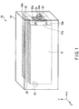
- FIG. 1 is a perspective view showing the external of the secondary battery 10 according to the present approach.
- FIG. 2 and FIG. 3 are exploded perspective views showing the configuration of an electrode group stack of the secondary battery 10.
- FIG. 4 and FIG. 5 are sectional views of FIG. 1 .
- the secondary battery 10 shown in FIG. 1 to FIG. 5 comprises an electrode group stack 11, and a container member 12 which houses the electrode group stack 11.
- the secondary battery 10 is rectangularly configured, and has a negative electrode terminal 24 provided on one side of the container member 12 in the X-direction, and a positive electrode terminal 25 provided on the other side.
- the electrode group stack 11 comprises electrode groups 21 and 22, an electrolyte (not shown). with which the electrode groups 21 and 22 are impregnated so that the electrolyte is held therein, a lead 23 which is a connector to electrically connect the electrode groups 21 and 22, external connection terminals 24 and 25 connected to the ends of the respective electrode groups 21 and 22, and an insulating sheet 26 disposed between the electrode groups 21 and 22 that are stacked and arranged.
- the two electrode groups 21 and 22 that are connected in series by the lead 23 disposed on the other side in the X-direction are stacked across the insulating sheet 26 in the Z-direction.
- the present approach four negative electrodes 31 and three positive electrodes 32 are alternately stacked in the Z-direction by way of example.
- four negative electrodes 34 and three positive electrodes 35 are alternately stacked in the Z-direction by way of example.
- the negative electrodes 31 and 34 comprise current collectors 31c and 34c, and negative electrode layers 31d and 34d formed on one surface or both surfaces of the current collectors 31c and 34c.
- the negative electrode layers 31d and 34d include an active material, a conductive agent, and a binder.
- the negative electrode tabs 31a and 34a protrude in the X-direction from any edges in the X-direction as parts of the current collectors 31c and 34c.
- the positive electrodes 32 and 35 comprise current collectors 32c and 35c, and positive electrode layers 32d and 35d formed on one surface or both surfaces of the current collectors 32c and 35c.
- the positive electrode layers 32d and 25d include an active material, a conductive agent, and a binder.
- the positive electrode tabs 32a and 35a protrude in the X-direction from any edges in the X-direction as parts of the current collectors 32c and 35c.
- the negative electrode tabs of one of a pair of electrode groups 21 and 22 and the positive electrode tabs of the other electrode group are aligned in the Z-direction. That is, in the present approach, the positive electrode tabs 32a of the first electrode group 21 and the negative electrode tabs 34a of the second electrode group 22 are aligned in the Z-direction on the same edge of the stack 11 on one side in the X-direction, collected in one place, and connected in series by the lead 23.
- the positive electrode tabs 32a of the first electrode group 21 and the negative electrode tabs 34a of the second electrode group 22 are collected at the middle position of the stack 11 in the X-direction, for example, by the lead 23.
- the positive electrode tabs 35a on one side and the negative electrode tabs 31a on the other side that are not connected by the lead 23 respectively extend from one side and the other side in the X-direction, and are respectively connected to the terminals 24 and 25.
- the negative electrode tabs 31a extend from one side in the X-direction and are thus connected to the terminal 24, and the positive electrode tabs 35a extend from the other side and are thus connected to the terminal 25.
- pairs of positive electrode tabs 32a and pairs of negative electrode tabs 34a which are connected to the lead 23 are provided on both sides in the Y-direction.
- the positive electrode tabs 35a and the negative electrode tabs 31a which are connected to the terminals 24 and 25 are provided one by one in the middle of the Y-direction. Rows of the positive electrode tabs 32a and the negative electrode tabs 34a and rows of the positive electrode tabs 35a and the negative electrode tabs 31a are different in position in the Y-direction, and are arranged without overlap.
- a total dimension of a pair of positive and negative electrode tabs 35a and 34a on both sides in the Y-direction is set at about the same as the dimensions of one positive electrode tab 35a and one negative electrode tab 31a in the middle.
- a Y-direction dimension Y1 of a pair of positive electrode tabs 32a and a pair of negative electrode tabs 34a is set at 1/2 times a Y-direction dimension Y2 of the positive electrode tabs 32a and the negative electrode tabs 34a provided in the middle.
- the positive electrode tabs 32a and the negative electrode tabs 34a are set at 1/4 Y0, and the positive electrode tabs 35a and the negative electrode tabs 31a are set at 1/2 Y0. Therefore, the lead-out directions of the tabs connected to different terminals are separated, and the tabs connected to each other are aligned, whereby the lead-out distance of the electrodes can be reduced, and connection processing can be easier. It is thus possible to minimize the distance of the lead 23.
- the dimension of each tab is equally set, and the dimensions of the current collectors 31c, 32c, 34c, and 35c are distributed, whereby the sectional area of each tab is increased, and energy density can be improved accordingly.
- aluminum foil or aluminum alloy foil having a purity of 98% or more is preferred.
- the aluminum alloy an alloy including one or more kinds of elements selected from the group consisting of iron, magnesium, zinc, manganese, and silicon in addition to aluminum is preferred.
- an Al-Fe alloy, an Al-Mn-based alloy, and an Al-Mg-based alloy are able to obtain higher strength than that of aluminum.
- a content of aluminum and transition metals such as nickel, chromium, etc., in the aluminum alloy is preferably 100 ppm or less (including 0 ppm).
- the Al-Cu-based alloy has increased strength, but deteriorated corrosion resistance, and thus, the Al-Cu-based alloy is not suitable as the current collector.
- a still preferable aluminum purity is in a range of 99.95% to 98.0%. This purity range is appropriate because titanium-containing oxide particles having an average secondary particle diameter of 2 ⁇ m or more is used to reduce a negative electrode pressing pressure so that elongation of the Al foil may be reduced. As a result, electron conductivity of the aluminum foil current collector may be increased, and in addition to this advantage, disintegration of the secondary particles of the titanium-containing oxide is suppressed, whereby a low-resistance negative electrode can be produced.
- the average particle diameter (diameter) of the secondary particles of the negative electrode active material is larger than 5 ⁇ m. It is still preferred that the secondary particle diameter of the negative electrode active material is 7 ⁇ m to 20 ⁇ m. Within this range, a high-density negative electrode can be produced while a low pressure of a negative electrode press is kept, and elongation of the aluminum foil current collector can be suppressed.
- the negative electrode active material in which the average particle diameter of the secondary particles is larger than 5 ⁇ m is obtained as follows: active material raw materials are reacted to synthetically prepare an active material precursor having an average particle diameter of 1 ⁇ m or less, and the active material precursor is fired and pulverized by use of a pulverizer such as a ball mill, a jet mill, etc., and then in a firing treatment, the active material precursor is agglomerated to be grown into the secondary particles having a large particle diameter.
- the average particle diameter of primary particles is desirably 1 ⁇ m or less. This allows the above effects to be noticeable in high-input performance (quick charge). This is because, for example, a diffusion distance of lithium ions in the active material is shortened and the specific surface area is increased.
- a still preferred average particle diameter is 0.1 to 0.8 ⁇ m.
- a carbon material to reduce the resistance of the negative electrode. This can be produced, for example, by adding a precursor of the carbon material in a process of producing the secondary particles, and firing at a temperature of 500°C or higher under an inert atmosphere.
- the secondary particles and the primary particles of titanium-containing oxide may be mixed in the negative electrode layer after the production of the negative electrode.
- the primary particles are present in an amount of 5 vol% to 50 vol% in the negative electrode layer.
- Examples of the negative electrode active material that can have lithium ions inserted and extracted may include a carbon material, a graphite material, a lithium alloy material, a metal oxide, and a metal sulfide. Among them, it is preferred to select negative electrode active material particles of at least one or more kinds of Ti-containing oxides selected from lithium-titanium oxide, titanium oxide, niobium-titanium oxide, and lithium-sodium-niobium-titanium oxide which have a potential of having lithium ions inserted and extracted within a range of 1 V to 3 V based on an Li potential.
- the titanium-containing oxide may include a spinel structure lithium-titanium oxide represented by General Formula Li 4+x Ti 5 O 12 (-1 ⁇ x ⁇ 3), a lithium-titanium oxide as a ramsdellite structure lithium-titanium oxide such as Li 2+x Ti 3 O 7 , Li 1+x Ti 2 O 4 , Li 1.1+x Ti 1.8 O 4 , Li 1.07+x Ti 1.86 O 4 , and Li x TiO 2 (0 ⁇ x), titanium oxide (TiO 2 as a structure before charging) having a monoclinic structure (TiO 2 (B) as a structure before charging), a rutile structure, or an anatase structure represented by General Formula Li x TiO 2 (0 ⁇ x), and niobium-titanium oxide represented by Li a TiM b Nb 2 ⁇ O 7 ⁇ (0 ⁇ a ⁇ 5, 0 ⁇ b ⁇ 0.3, 0 ⁇ ⁇ ⁇ 0.3, 0
- the spinel structure lithium-titanium oxide represented by General Formula Li 4+x Ti 5 O 12 (-1 ⁇ x ⁇ 3) with a very small volume change is still preferred.
- the use of the titanium-containing oxides permits the aluminum foil to be used as a negative electrode current collector in the same manner as a positive electrode current collector instead of conventional copper foils, thereby enabling weight and cost reductions. This is also advantageous to a bipolar electrode structure.
- the average particle diameter of the negative electrode active material is set to the above-described range because when the specific surface area of the negative electrode is increased to 3 m 2 /g to 50 m 2 /g by use of the primary particles having an average particle diameter of more than 1 ⁇ m, reduction in porosity of the negative electrode cannot be avoided.
- a lower limit value is preferably set to be 0.001 ⁇ m.
- the negative electrode active material preferably has an average particle diameter of 1 ⁇ m or less, and has a specific surface area measured according to the BET method by N 2 adsorption ranging from 3 m 2 /g to 200 m 2 /g. Accordingly, affinity between the negative electrode and the nonaqueous electrolyte can be further increased.
- the specific surface area of the negative electrode is defined in the above range.
- the specific surface area is less than 3 m 2 /g, the agglomeration of the particles is prominent, and the affinity between the negative electrode and the nonaqueous electrolyte is lowered, which increases interface resistance of the negative electrode, and as a result, output characteristics and charge and discharge cycle characteristics are deteriorated.
- the specific surface area is more than 50 m 2 /g, the distribution of the nonaqueous electrolyte is biased toward the negative electrode, resulting in a shortage of the nonaqueous electrolyte in the positive electrode, and thus, the output characteristics and the charge and discharge cycle characteristics cannot be improved.
- a still preferred range of the specific surface area is 5 m 2 /g to 50 m 2 /g.
- the specific surface area of the negative electrode means the surface area per 1 g of the negative electrode layer (excluding the weight of the current collector).
- the negative electrode layer is a porous layer including the negative electrode active material, the conductive agent, and the binder, which are supported on the current collector.
- porosity of the negative electrode is within a range of 20% to 50%. Accordingly, it is possible to obtain a negative electrode having excellent affinity between the negative electrode and the electrolyte and having a high density. A still preferable range of the porosity is 25% to 40%.
- the negative electrode current collector is desirably aluminum foil or aluminum alloy foil.
- the thickness of the aluminum foil and the aluminum alloy foil is 20 ⁇ m or less, and still preferably 15 ⁇ m or less.
- the purity of the aluminum foil is preferably 99.99% or more.
- the aluminum alloy is preferably an alloy including elements such as magnesium, zinc, and silicon.
- transition metals such as iron, copper, nickel, and chromium are preferably 100 ppm or less.
- a carbon material can be used as the conductive agent.
- the carbon material may include acetylene black, carbon black, cokes, carbon fiber, graphite, aluminum powder, TiO, etc.
- the BET specific surface area of these carbon materials by N 2 adsorption is preferably 10 m 2 /g or more.
- binder examples include polytetrafluoroethylene (PTFE), polyvinylidene fluoride (PVdF), fluorine-based rubber, styrene butadiene rubber, and core shell binder, etc.
- PTFE polytetrafluoroethylene
- PVdF polyvinylidene fluoride
- fluorine-based rubber examples include polytyrene butadiene rubber, and core shell binder, etc.
- the negative electrode active material is preferably in a range of 80 wt% to 95 wt%
- the conductive agent is preferably in a range of 3 wt% to 18 wt%
- the binder is preferably in a range of 2 wt% to 7 wt%.
- the negative electrode is produced by the suspension of the above-described negative electrode active material, the conductive agent, and the binder in an appropriate solvent, the application of the suspension to the current collector, drying, and heating press.
- the particles of the negative electrode active material are uniformly dispersed in a state where the addition amount of the binder is small. The reason is that if an addition amount of the binder is larger, dispersibility of the particles tends to be increased, but the surface of the particles is easily covered with the binder, and thus, the specific surface area of the negative electrode is reduced.
- stirring conditions the number of revolutions of a ball mill, stirring time and stirring temperature
- the addition amount of the binder and the stirring conditions are included within appropriate ranges but the addition amount of the conductive agent is large, the surface of the negative electrode active material is easily covered with the conductive agent, and pores on the surface of the negative electrode also tend to decrease, and thus, the specific surface area of the negative electrode tends to be smaller.
- the addition amount of the conductive agent is small, the negative electrode active material is easily pulverized, and thus, the specific surface area of the negative electrode tends to be large, or dispersibility of the negative electrode active material is lowered, and thus, the specific surface area of the negative electrode tends to be smaller.
- the conductive agent has an average particle diameter which is the same as or less than the average particle diameter of the negative electrode active material, and a specific surface area larger than that of the negative electrode active material.
- the positive electrode current collector aluminum foil or aluminum alloy foil having a purity of 99% or more.
- the aluminum alloy an alloy including one or more kinds of elements selected from the group consisting of iron, magnesium, zinc, manganese, and silicon in addition to aluminum is preferred.
- an Al-Fe alloy, an Al-Mn-based alloy, and an Al-Mg-based alloy are able to obtain higher strength than that of aluminum.
- a content of aluminum and transition metals such as nickel, chromium, etc., in the aluminum alloy is preferably 100 ppm or less (including 0 ppm).
- the Al-Cu-based alloy has increased strength, but deteriorated corrosion resistance, and thus, the Al-Cu-based alloy is not suitable as the current collector.
- a still preferable aluminum purity is in a range of 99.99% to 99.0%. Within this range, deterioration of a high-temperature cycle lifespan due to dissolution of impurity elements can be reduced.
- Examples of the positive electrode active material may include lithium-manganese composite oxide, lithium-nickel composite oxide, lithium-cobalt-aluminum composite oxide, lithium-nickel-cobalt-manganese composite oxide, spinel type lithium-manganese-nickel composite oxide, lithium-manganese-cobalt composite oxide, olivine type lithium iron phosphate (LiFePO 4 ) or lithium manganese phosphate (LiMnPO 4 ), etc.
- lithium-manganese composite oxide lithium-nickel composite oxide, lithium-cobalt-aluminum composite oxide, lithium-nickel-cobalt-manganese composite oxide, spinel type lithium-manganese-nickel composite oxide, lithium-manganese-cobalt composite oxide, olivine type lithium iron phosphate (LiFePO 4 ) or lithium manganese phosphate (LiMnPO 4 ), etc.
- the lithium-manganese composite oxides such as Li x Mn 2 O 4 or Li x MnO 2 etc., lithium-nickel-aluminum composite oxides such as Li x Ni 1-y Al y O 2 , etc., lithium-cobalt composite oxides such as Li x CoO 2 , etc., lithium-nickel-cobalt composite oxides such as Li x Ni 1-y-z Co y Mn z O 2 , etc., lithium-manganese-cobalt composite oxides such as Li x Mn y Co 1-y O 2 , etc., the spinel type lithium-manganese-nickel composite oxides such as Li x Mn 2-y Ni y O 4 , etc., lithium phosphate having an olivine structure such as Li x FePO 4 , Li x Fe 1-y Mn y PO 4 , Li x CoPO 4 , etc., for example, fluorinated iron sulfate Li x FeSO 4 F
- the lithium-nickel-aluminum composite oxide, the lithium-nickel-cobalt-manganese composite oxide, and the lithium-manganese-cobalt composite oxide can suppress the reaction with the electrolyte under a high temperature environment to greatly improve battery lifespan.
- the lithium-nickel-cobalt-manganese composite oxide that can be represented by Li x Ni 1-y-z Co y Mn z O 2 (0 ⁇ x ⁇ 1.1, 0 ⁇ y ⁇ 0.5, 0 ⁇ z ⁇ 0.5) is preferred.
- High temperature durability lifespan can be obtained by using the lithium-nickel-cobalt-manganese composite oxide.
- the conductive agent to increase electron conductivity and to suppress the resistance of contact with the current collector may include, for example, acetylene black, carbon black, or graphite, etc.
- the binder to bind the active material and the conductive agent may include, for example, polytetrafluoroethylene (PTFE), polyvinylidene fluoride (PVdF), fluorine-based rubber, etc.
- PTFE polytetrafluoroethylene
- PVdF polyvinylidene fluoride
- fluorine-based rubber etc.
- the positive electrode active material is preferably in a range of 80 wt% to 95 wt%
- the conductive agent is preferably in a range of 3 wt% to 18 wt%
- the binder is preferably in a range of 2 wt% to 7 wt%.
- a content of the conductive agent is 3 wt% or more, the above-described effect can be exhibited, and when the content of the conductive agent is 18 wt% or less, decomposition of the electrolyte on the surface of the conductive agent under high temperature can be reduced.
- a content of the binder is 2 wt% or more, sufficient electrode strength can be obtained, and when the content of the binder is 7 wt% or less, an insulating part of the electrode may be reduced.
- the positive electrode is produced, for example, by the suspension of the positive electrode active material, the conductive agent, and the binder in an appropriate solvent, the application of the suspension to the positive electrode current collector, drying, and pressing.
- a pressure of pressing the positive electrode is preferably in a range of 0.15 ton/mm to 0.3 ton/mm. This range is preferred because adhesion property (peel strength) between the positive electrode layer and the aluminum foil positive electrode current collector is increased and an elongation rate of a positive electrode current collector foil is 20% or less.
- the separator 33 is formed into a rectangular sheet shape.
- a porous film or synthetic resin nonwoven fabric including polyethylene, polypropylene, cellulose, or polyvinylidene fluoride (PVdF) is used as the separator 33.
- a preferable porous film is formed from polyethylene or polypropylene, melts at a fixed temperature, can shut off a current, and can therefore improve safety.
- insulating particles may be formed on one surface or both surfaces of the positive electrode and/or the negative electrode as the separator 33.
- the insulating particles include metal oxides.
- the use of a solid electrolyte as insulating particles can reduce the resistance of the secondary battery.
- electrolyte for example, a liquid nonaqueous electrolyte which is prepared by dissolving electrolyte salt in an organic solvent, or gel like nonaqueous electrolyte which is a composite of a liquid electrolyte and a polymer material.
- the liquid nonaqueous electrolyte is preferably electrolyte salt dissolved in an organic solvent at a concentration of 0.5 M to 2.5 M.
- the electrolyte salt may include lithium salts such as lithium perchlorate (LiClO 4 ), lithium hexafluorophosphate (LiPF 6 ), lithium tetrafluoroborate (LiBF 4 ), lithium hexafluoroarsenate (LiAsF 6 ), lithium trifluoromethanesulfonate (LiCF 3 SO 3 ), and lithium bistrifluoromethylsulfonylimide [LiN(CF 3 SO 2 ) 2 ], and mixtures thereof.
- the electrolyte salt is preferably resistant to oxidation even at a high potential, and most preferably LiPF 6 .
- organic solvent examples include a cyclic carbonate such as propylene carbonate (PC), ethylene carbonate (EC), or vinylene carbonate; a linear carbonate such as diethyl carbonate (DEC), dimethyl carbonate (DMC), or methyl ethyl carbonate (MEC); a cyclic ether such as tetrahydrofuran (THF), 2-methyl tetrahydrofuran (2-MeTHF), or dioxolane (DOX); a linear ether such as dimethoxy ethane (DME) or diethoxy ethane (DEE); ⁇ -butyrolactone (GBL), acetonitrile (AN), and sulfolane (SL).
- a cyclic carbonate such as propylene carbonate (PC), ethylene carbonate (EC), or vinylene carbonate
- a linear carbonate such as diethyl carbonate (DEC), dimethyl carbonate (DMC), or methyl ethyl carbonate (
- polymeric material examples include polyvinylidene fluoride (PVdF), polyacrylonitrile (PAN), and polyethylene oxide (PEO).
- PVdF polyvinylidene fluoride
- PAN polyacrylonitrile
- PEO polyethylene oxide
- a preferable organic solvent is a mixed solvent in which at least two or more of a group consisting of propylene carbonate (PC), ethylene carbonate (EC), and diethyl carbonate (DEC) are mixed, or a mixed solvent including ⁇ -butyrolactone (GBL).
- PC propylene carbonate
- EC ethylene carbonate
- DEC diethyl carbonate
- GBL ⁇ -butyrolactone
- the electrode groups 21 and 22 are connected by the lead 23. Specially, the positive electrodes 32 of one electrode group 21 are connected in series to the negative electrodes 34 of the other electrode group 22 by the lead 23.
- the lead 23 is made of a metallic material, and is connected to the edges of the other ends of the electrode groups 21, 21 in the X-direction.
- the lead 23 comprises strip-shaped connection pieces 23a having the same width as the width of the tabs 32a and 34a.
- the respective connection pieces 23a are joined to the tabs 34a and 32a on one end, and collectively joined to each other in one place on the other end.
- the lead 23 is connected to the positive electrode tabs 32a of one electrode group 21 and the negative electrode tabs 34a of the other electrode group 22, and thereby connects a pair of electrode groups 21 and 22 in series.
- aluminum foil or aluminum alloy foil having a purity of 98% or more is preferred.
- the aluminum alloy an alloy including one or more kinds of elements selected from the group consisting of iron, magnesium, zinc, manganese, and silicon in addition to aluminum is preferred.
- an Al-Fe alloy, an Al-Mn-based alloy, and an Al-Mg-based alloy are able to obtain higher strength than that of aluminum.
- a content of aluminum and transition metals such as nickel, chromium, etc., in the aluminum alloy is preferably 100 ppm or less (including 0 ppm).
- the Al-Cu-based alloy has increased strength, but deteriorated corrosion resistance, and thus, the Al-Cu-based alloy is not suitable as the lead.
- a still preferable aluminum purity is in a range of 99.95% to 98.0%.
- the thickness of this lead is preferably 20 ⁇ m or more. An excessively great thickness leads to deterioration in handling efficiency or deterioration in capacity per unit volume, and the thickness is therefore preferably 1 mm or less, still preferably 500 ⁇ m or less, and yet preferably 200 ⁇ m or less.
- the insulating sheet 26 is an electrically and ion-conductively insulating sheet, and, for example, polypropylene (PP), polyethylene (PE), nylon, or polyethylene terephthalate (PET) can be used as the insulating sheet 26.
- PP polypropylene
- PE polyethylene
- PET polyethylene terephthalate
- the insulating sheet 26 is fusion-bonded to the container member 12, it is preferable to use a material having a thermal fusion bond temperature close to those of the insulating sheet 26 and a resin part of the container member 12.
- the insulating sheet 26 is a rectangular sheet larger in area than the surfaces of the electrode groups 21, 21 facing each other. That is, an outer peripheral edge 26a of the insulating sheet 26 protrudes outward more than the outer peripheral edges of the electrode groups 21, 21 in an XY plane.
- the insulating sheet 26 forms, between the stacked electrode groups 21, 21, a partition which divides the internal space of the container member 12 into one side and the other side in the Z-direction.
- the container member 12 is made of, for example, a metallic container.
- the metallic container is formed into a box shape having a thickness of 1.0 mm or less.
- the metallic container preferably has a thickness of 0.5 mm or less.
- the metallic container is made of aluminum or aluminum alloy.
- the aluminum alloy an alloy including an element such as magnesium, zinc, or silicon is preferred.
- the alloy includes a transition metal such as iron, copper, nickel, or chromium, its amount is preferably 100 mass ppm or less.
- the metallic container is preferably an alloy which includes an element such as manganese, magnesium, zinc, or silicon and which has an aluminum purity of 99.8% or less.
- a significant increase in the strength of a metal can comprising the aluminum alloy permits a reduction in the thickness of the can. As a result, it is possible to obtain a battery having a small thickness and weight, a high output, and high heat release performance.
- the container member 12 can be formed into, for example, a flat shape (thin shape), a circular cylindrical shape, a coin shape, and a button shape in addition to a square shape.
- the container member 12 includes, for example, a small battery container member mounted on a portable electronic device or the like, and a large battery container member mounted on a two-wheeled or four-wheeled vehicle, a railway vehicle, or the like, in accordance with battery dimensions.
- the positive electrode tabs 32a of one electrode group and the negative electrode tabs 34a of the other electrode group that are connected in series in the container member 12 are aligned in the Z-direction which is a stacking direction. It is thus possible to minimize the connecting distance, reduce the resistance between the electrode groups 21 and 22, and increase energy density.
- the secondary battery 10 has the external connection terminals 24 and 25 that are respectively lead out of one side and the other in the X-direction, and can therefore have the advantage of being able to prevent a short circuit from being caused by the contact between the terminals.
- the tabs 31a and 35a in the middle are separate from a pair of tabs 32a and 34a on both sides, and the tabs connected to the different terminals 24 and 25 are located apart from each other, so that connecting work can be accurately and easily conducted.
- the total dimension of the tabs 31a, 32a, 34a, and 35a in the Y-direction is formed into a uniform dimension to have a certain uniform sectional area, which makes it possible to provide the advantageous effects of being able to minimize electric resistance.
- the aligned tabs 32a and 34a are collectively connected to the lead 23 in one place, so that the connecting length can be shorter than when the positive electrode tabs 32a and the negative electrode tabs 34a are independently collected and then connected to the common lead.
- two or more electrode groups are stacked in a first direction and comprise negative electrodes comprising negative electrode tabs and positive electrodes comprising positive electrode tabs that are alternately stacked, and the negative electrode tabs of one of the electrode groups and the positive electrode tabs of the other electrode group are arranged in rows in the first direction at one end of a stack in a second direction, and electrically connected in series by a connector.
- One of the positive electrode tabs of one of the electrode groups and the negative electrode tabs of the other electrode group is disposed at the other end in the second direction, and the other is disposed, at one end in the second direction, at a position different from those of the negative electrode tabs of one of the electrode groups and the positive electrode tabs of the other electrode group that are connected in series. It is thus possible to minimize the connecting distance of the series connection, reduce the resistance between the electrode groups, and increase energy density. Because the external connection positive electrode tabs and negative electrode tabs are respectively disposed on one side and the other, a short circuit caused by the contact between the terminals can be prevented.
- a secondary battery 110 according to a second approach is described below with reference to FIG. 6 to FIG. 9 .
- the secondary battery 110 according to the second approach is different in the arrangement of the negative electrode tabs 31a and 34a and the positive electrode tabs 32a and 35a compared to the first approach, but similar in other respects to the secondary battery 10 according to the first approach.
- the same configurations in the present approach as those in the first approach are not repeatedly described.
- the secondary battery 110 shown in FIG. 6 to FIG. 9 comprises an electrode group stack 11, and a container member 12 which houses the electrode group stack 11.
- the secondary battery 110 is rectangularly configured, and has a negative electrode external connection terminal 24 provided on one side of the container member 12 in the X-direction, and a positive electrode external connection terminal 25 provided on the other side.
- the electrode group stack 11 comprises electrode groups 21 and 22, an electrolyte with which the electrode groups 21, 21 are impregnated so that the electrolyte is held therein, a lead 23 which is a connector to electrically connect the electrode groups 21 and 22, external connection terminals 24 and 25 connected to the ends of the respective electrode groups 21 and 22, and an insulating sheet 26 disposed between the electrode groups 21 and 22 that are stacked and arranged.
- the two electrode groups 21 and 22 that are connected in series by the lead 23 disposed on the other side in the X-direction are stacked across the insulating sheet 26 in the Z-direction.
- the top first electrode group 21 in FIG. 7 comprises negative electrodes 31 having negative electrode tabs 31a, positive electrodes 32 having positive electrode tabs 32a, a separator 33 disposed between the negative electrode 31 and the positive electrode 32, and a nonaqueous electrolyte with which the negative electrodes 31 and the positive electrodes 32 are impregnated.
- three negative electrodes 31 and four positive electrodes 32 are alternately stacked in the Z-direction by way of example.
- the bottom second electrode group 22 in FIG. 7 comprises negative electrodes 34 having negative electrode tabs 34a, positive electrodes 35 having positive electrode tabs 35a, a separator 36 disposed between the negative electrode 34 and the positive electrode 35, and a nonaqueous electrolyte with which the negative electrodes 34 and the positive electrodes 35 are impregnated.
- the present approach four negative electrodes 34 and three positive electrodes 35 are alternately stacked in the Z-direction by way of example.
- the negative electrodes 31 and 34 comprise current collectors 31c and 34c, and negative electrode layers 31d and 34d formed on one surface or both surfaces of the current collectors 31c and 34c.
- the negative electrode layers 31d and 34d include an active material, a conductive agent, and a binder.
- the negative electrode tabs 31a and 34a protrude in the X-direction from any edges in the X-direction as parts of the current collectors 31c and 34c.
- the positive electrodes 32 and 35 comprise current collectors 32c and 35c, and positive electrode layers 32d and 35d formed on one surface or both surfaces of the current collectors 32c and 35c.
- the positive electrode layers 32d and 25d include an active material, a conductive agent, and a binder.
- the positive electrode tabs 32a and 35a protrude in the X-direction from any edges in the X-direction as parts of the current collectors 32c and 35c.
- the negative electrode tabs of one of a pair of electrode groups 21 and 22 and the positive electrode tabs of the other electrode group are aligned in the Z-direction. That is, in the present approach, the positive electrode tabs 32a of the first electrode group 21 and the negative electrode tabs 34a of the second electrode group 22 are aligned in the Z-direction on the same edge of the stack 11 on one side in the X-direction, collected in one place, and connected in series by the lead 23.
- the positive electrode tabs 32a of the first electrode group 21 and the negative electrode tabs 34a of the second electrode group 22 are collected at the middle position of the stack 11 in the X-direction, for example, by the lead 23.
- the positive electrode tabs 35a on one side and the negative electrode tabs 31a on the other side that are not connected by the lead 23 respectively extend from one side and the other side in the X-direction, and are respectively connected to the terminals 24 and 25.
- the negative electrode tabs 31a extend from one side in the X-direction and are thus connected to the terminal 24, and the positive electrode tabs 35a extend from the other side and are thus connected to the terminal 25.
- the positive electrode tabs 32a and the negative electrode tabs 34a that are connected to the lead 23 are provided on one side in the Y-direction.
- the positive electrode tabs 35a and the negative electrode tabs 31a that are connected to the terminals 24 and 25 are provided on the opposite sides in the Y-direction. That is, the positive electrode tabs 35a and the negative electrode tabs 31a are disposed close to one side of the Y-direction, whereas the positive electrode tabs 32a and the negative electrode tabs 34a are disposed close to the other side of the Y-direction.
- Rows of the positive electrode tabs 32a and the negative electrode tabs 34a and rows of the negative electrode tabs 31a extend from edges at one end in the X-direction, but are different in position in the Y-direction, and are arranged without overlap.
- the positive electrode tabs 35a extend from an edge at the other end in the X-direction.
- all of the positive electrode tabs 32a and 35a and the negative electrode tabs 31a and 34a are set at about the same dimension in the Y-direction.
- the Y-direction dimension of, for example, the positive electrodes 32 and 35 and the negative electrodes 31 and 34 is Y0
- all of the positive electrode tabs 32a and 35a and the negative electrode tabs 31a and 34a are set at 1/4 Y0 to 1/2 Y0.
- the electrode groups 21 and 22 are connected by the lead 23. Specially, the positive electrode tabs 32a of one electrode group 21 are connected in series to the negative electrode tabs 34a of the other electrode group 22 by the lead 23.
- the lead 23 is made of a metallic material.
- the lead 23 is connected to the edges of the electrode groups 21 and 22 on one side in the X-direction.
- the lead 23 comprises connection pieces 23a.
- the respective connection pieces 23a are connected to the tabs 32a and 34a on one end, and collectively joined to each other in one place on the other end. That is, the lead 23 is connected to the positive electrode tabs 32a of the positive electrodes 32 of one electrode group 21 and the negative electrode tabs 34a of the negative electrodes 34 of the other electrode group 22, and thereby connects a pair of electrode groups 21 and 22 in series.
- the lead-out directions of the tabs connected to different terminals are separated, and the tabs connected to each other are aligned, whereby the connecting distance of the electrodes is reduced, and thus connection processing can be easier. It is thus possible to minimize the distance of the lead 23.
- the dimensions of the current collectors are distributed so that the dimension of each tab is equally set, whereby the sectional area of each tab is increased, and energy density can be improved accordingly.
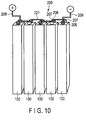
- FIG. 10 is a perspective view schematically showing an example of the battery module according to the third approach.
- the battery module according to the third approach includes plural single batteries 100. Each of the single batteries may be arranged electrically connected in series, in parallel, or in a combination of in-series connection and in-parallel connection.
- a battery module 200 shown in FIG. 10 includes five single-batteries 100, four bus bars 221, a positive electrode-side lead 22, and a negative electrode-side lead 209.
- At least one of the single-batteries 100 is a secondary battery 10 according to the first approach or secondary battery 110 according to the second approach.
- Each bus bar 221 connects a negative electrode terminal 206 of one single-battery 100 and a positive electrode terminal 207 of the single-battery 100 positioned adjacent.
- the five single-batteries 100 are thus connected in series by the four bus bars 221. That is, the battery module 200 shown in FIG. 12 is a battery module of five in-series connection.
- the positive electrode terminal 207 of the single-battery 100 located at one end on the left among the row of the five single-batteries 100 is connected to the positive electrode-side lead 208for external connection.
- the negative electrode terminal 206 of the single-battery 100 located at the other end on the right among the row of the five single-batteries 100 is connected to the negative electrode-side lead 209 for external connection.
- the battery module 200 uses the secondary batteries 10 and 110 as the unit cells 100, and can thereby reduce the connecting distance of the series connection in each of the unit cells 100 to reduce resistance. That is, according to the third approach, the positive electrode tabs and the negative electrode tabs that are connected in series to each other are aligned in the stacking direction in the electrode groups, and the connecting distance can be thereby reduced to reduce resistance.
- FIG. 11 is a perspective view schematically showing an example of the battery module according to the third approach.
- FIG. 11 is an exploded perspective view schematically showing an example of the battery pack according to the fourth approach.
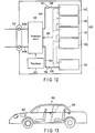
- FIG. 12 is a block diagram showing an example of an electric circuit of the battery pack shown in FIG. 11 .
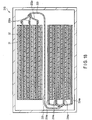
- a battery pack 300 shown in FIGS. 11 and 12 includes a housing container 331, a lid 332, protective sheets 333, a battery module 200, a printed wiring board 334, wires 335, and an insulating plate (not shown).
- the battery module 200 is the battery module 200 according to the third approach and the battery module 200 has one or more secondary batteries 10 or 110.
- the housing container 331 is configured to house the protective sheets 333, the battery module 200, the printed wiring board 334, and the wires 335.
- the lid 332 covers the housing container 331 to house the battery module 200 and the like. Although not shown, opening(s) or connection terminal(s) for connecting to external device(s) and the like are provided on the housing container 331 and lid 332.
- the protective sheets 333 are arranged on both inner surfaces of the housing container 331 along the long-side direction and on the inner surface along the short-side direction, facing the printed wiring board 334 across the battery module 200 positioned therebetween.
- the protective sheets 333 are made of, for example, resin or rubber.
- the battery module 200 includes plural single-batteries 100, a positive electrode-side lead 208, a negative electrode-side lead 209, and an adhesive tape 224.
- the battery module 200 may alternatively include only one single-battery 100.
- At least one of the plural single-batteries 100 is a secondary battery 10 or 110 according to the first or second approach.
- the plural single-batteries 100 are stacked such that the negative electrode terminals 206 and the positive electrode terminals 207, which extend outside, are directed toward the same direction.
- the plural single-batteries 100 are electrically connected in series, as shown in FIG. 14 .
- the plural single-batteries 100 may alternatively be electrically connected in parallel, or connected in a combination of in-series connection and in-parallel connection. If the plural single-batteries 100 are connected in parallel, the battery capacity increases as compared to a case in which they are connected in series.
- the adhesive tape 224 fastens the plural single-batteries 100.
- the plural single-batteries 100 may be fixed using a heat-shrinkable tape in place of the adhesive tape 224.
- the protective sheets 333 are arranged on both side surfaces of the battery module 200, and the heat-shrinkable tape is wound around the battery module 200 and protective sheets 333. After that, the heat-shrinkable tape is shrunk by heating to bundle the plural single-batteries 100.
- One end of the positive electrode-side lead 208 is connected to the positive electrode terminal 207 of the single-battery 100 located lowermost in the stack of the single-batteries 100.
- One end of the negative electrode-side lead 209 is connected to the negative electrode terminal 206 of the single-battery 100 located uppermost in the stack of the single-batteries 100.
- the printed wiring board 334 includes a positive electrode-side connector 341, a negative electrode-side connector 342, a thermistor 343, a protective circuit 344, wirings 345 and 346, an external power distribution terminal 347, a plus-side (positive-side) wire 348a, and a minus-side (negative-side) wire 348b.
- One principal surface of the printed wiring board 334 faces the surface of the battery module 200 from which the negative electrode terminals 206 and the positive electrode terminals 207 extend out.
- An insulating plate (not shown) is disposed in between the printed wiring board 334 and the battery module 200.
- the positive electrode-side connector 341 is provided with a through hole. By inserting the other end of the positive electrode-side lead 208into the though hole, the positive electrode-side connector 341 and the positive electrode-side lead 208become electrically connected.
- the negative electrode-side connector 342 is provided with a through hole. By inserting the other end of the negative electrode-side lead 209 into the though hole, the negative electrode-side connector 342 and the negative electrode-side lead 209 become electrically connected.
- the thermistor 343 is fixed to one principal surface of the printed wiring board 334.
- the thermistor 343 detects the temperature of each single-battery 100 and transmits detection signals to the protective circuit 344.
- the external power distribution terminal 347 is fixed to the other principal surface of the printed wiring board 334.
- the external power distribution terminal 347 is electrically connected to device(s) that exists outside the battery pack 300.
- the protective circuit 344 is fixed to the other principal surface of the printed wiring board 334.
- the protective circuit 344 is connected to the external power distribution terminal 347 via the plus-side wire 348a.
- the protective circuit 344 is connected to the external power distribution terminal 347 via the minus-side wire 348b.
- the protective circuit 344 is electrically connected to the positive electrode-side connector 341 via the wiring 345.
- the protective circuit 344 is electrically connected to the negative electrode-side connector 342 via the wiring 346.
- the protective circuit 344 is electrically connected to each of the plural single-batteries 100 via the wires 335.
- the protective circuit 344 controls charge and discharge of the plural single-batteries 100.
- the protective circuit 344 is also configured to cut-off electric connection between the protective circuit 344 and the external power distribution terminal 347, based on detection signals transmitted from the thermistor 343 or detection signals transmitted from each single-battery 100 or the battery module 200.
- An example of the detection signal transmitted from the thermistor 343 is a signal indicating that the temperature of the single-battery (single-batteries) 100 is detected to be a predetermined temperature or more.
- An example of the detection signal transmitted from each single-battery 100 or the battery module 200 is a signal indicating detection of over-charge, over-discharge, and overcurrent of the single-battery (single-batteries) 100.
- the battery voltage may be detected, or a positive electrode potential or negative electrode potential may be detected. In the latter case, a lithium electrode to be used as a reference electrode may be inserted into each single battery 100.
- the protective circuit 344 a circuit included in a device (for example, an electronic device or an automobile) that uses the battery pack 300 as a power source may be used.
- Such a battery pack 300 is used, for example, in applications where excellent cycle performance is demanded when a large current is extracted. More specifically, the battery pack 300 is used as, for example, a power source for electronic devices, a stationary battery, an onboard battery for vehicles, or a battery for railway cars. An example of the electronic device is a digital camera. The battery pack 300 is particularly favorably used as an onboard battery.
- the battery pack 300 includes the external power distribution terminal 347.
- the battery pack 300 can output current from the battery module 200 to an external device and input current from an external device to the battery module 200 via the external power distribution terminal 347.
- the current from the battery module 200 is supplied to an external device via the external power distribution terminal 347.
- a charge current from an external device is supplied to the battery pack 300 via the external power distribution terminal 347. If the battery pack 300 is used as an onboard battery, the regenerative energy of the motive force of a vehicle can be used as the charge current from the external device.
- the battery pack 300 may include plural battery modules 200.
- the plural battery modules 200 may be connected in series, in parallel, or connected in a combination of in-series connection and in-parallel connection.
- the printed wiring board 334 and the wires 335 may be omitted.
- the positive electrode-side lead 208 and the negative electrode-side lead 209 may be used as the external power distribution terminal.
- the battery pack 300 according to the fourth approach includes the secondary battery 10 according to the first approach, the secondary battery 110 according to the second approach or the battery module 200 according to the third approach and can thereby reduce the connecting distance of the series connection in each of the unit cells 100 to reduce resistance.
- the secondary battery includes the insulating sheet disposed between the electrode groups. It is thus possible to provide advantageous effects of preventing contact between the electrolyte and preventing a short circuit.
- the battery pack may include a single secondary battery 10,110 according to the first or the second approach, in place of the battery module according to the third approach.
- the battery pack 300 according to the fourth approach may further include a protective circuit.
- the protective circuit has a function to control charging and discharging of the secondary battery.
- a circuit included in equipment where the battery pack serves as a power source for example, electronic devices, vehicles, and the like may be used as the protective circuit for the battery pack.
- the battery pack 300 may further comprise an external power distribution terminal.
- the external power distribution terminal is configured to externally output current from the secondary battery, and to input external current into the secondary battery.
- the current is provided out via the external power distribution terminal.
- the charging current including regenerative energy of motive force of vehicles such as automobiles
- the external power distribution terminal is provided to the battery pack via the external power distribution terminal.
- FIG. 13 is a cross-sectional view schematically showing an example of a vehicle according to the fifth approach.
- a vehicle 400, shown in FIG. 13 includes a vehicle body 440 and a battery pack 300 according to the fourth approach.
- Examples of the vehicle 400 according to the fifth approach include two- to four-wheeled hybrid electric automobiles, two- to four-wheeled electric automobiles, electric assist bicycles, and railway cars.
- the battery pack 300 is configured, for example, to recover regenerative energy from motive force of the vehicle.
- the battery pack 300 includes the battery module 200 according to the third approach.
- the battery module 200 has plural single batteries 100 that are connected in series. At least one of the single batteries 100 is the second battery 10 of the first approach or the second battery 110 of the second approach
- the vehicle 400 is a four-wheeled automobile.
- vehicle 400 for example, two- to four-wheeled hybrid electric automobiles, two- to four-wheeled electric automobiles, electric assist bicycles, and railway cars may be used.
- This vehicle 400 may have plural battery packs 300 installed.
- the battery packs 300 may be connected in series, connected in parallel, or connected in a combination of in-series connection and in-parallel connection.
- the battery pack 300 is installed in an engine compartment located at the front of the vehicle body 40.
- the location of installing the battery pack 300 is not particularly limited.
- the battery pack 300 may be installed in rear sections of the vehicle body 40, or under a seat.
- the battery pack 300 may be used as a power source of the vehicle 400.
- the battery pack 300 can also recover regenerative energy of motive force of the vehicle 400.
- the vehicle 400 according to this approach includes the second battery 10 according to the first approach or the second battery 110 according to the second approach as the single battery 100, and can therefore prevent in the short circuit in single battery 100.
- the negative electrode tabs and the positive electrode tabs that are connected in series in the electrode groups are aligned in the Z-direction at one end in the X-direction, and it is thus possible to provide advantageous effects of reducing the connecting distance between the electrode groups and reducing resistance.
- FIG. 14 is a cross-sectional view schematically showing an example of a vehicle 400A according to the sixth approach.
- a vehicle 400A, shown in FIG. 14 is an electric automobile.
- the vehicle 400A shown in FIG. 10 , includes a vehicle body 440, a vehicle power source 441, a vehicle ECU (electric control unit) 442, which is a master controller of the vehicle power source 441, an external terminal (an external power connection terminal) 443, an inverter 444, and a drive motor 445.
- a vehicle body 440 a vehicle power source 441
- a vehicle ECU (electric control unit) 442 which is a master controller of the vehicle power source 441, an external terminal (an external power connection terminal) 443, an inverter 444, and a drive motor 445.
- the vehicle 400 includes the vehicle power source 441, for example, in the engine compartment, in the rear sections of the automobile body, or under a seat.
- the position of the vehicle power source 441 installed in the vehicle 400 is schematically shown.
- the vehicle power source 441 includes plural (for example, three) battery packs 300, a battery management unit (BMU) 411, and a communication bus 412.
- BMU battery management unit
- the three battery packs 300 are electrically connected in series.
- the battery pack 300 includes a battery module 200 and a battery module monitoring unit (VTM: voltage temperature monitoring) 301.
- VTM voltage temperature monitoring
- the battery packs 300 can each be independently removed, and may be exchanged by a different battery pack 300.
- At least one of the three battery packs300 is the battery pack 300 according to the fourth approach and at least one of the plural battery modules 200 is one of the battery modules 300 according to the third approach.
- Each of the battery modules 200 includes plural single-batteries100 connected in series. At least one of the plural single-batteries is the secondary battery 10 according to the first approach or the secondary battery 110 according to the second approach.
- the battery modules 200 each perform charging and discharging via a positive electrode terminal 413 and a negative electrode terminal 414.
- the battery management unit 411 performs communication with the battery module monitoring units 301 and collects information such as voltages or temperatures of the single-batteries 100 included in the battery modules 200 included in the vehicle power source 441.
- the communication bus 412 is connected between the battery management unit 411 and the battery module monitoring units 301.
- the communication bus 412 is configured so that multiple nodes (i.e., the battery management unit and one or more battery module monitoring units) share a set of communication lines.
- the communication bus 412 is, for example, a communication bus configured based on CAN (Control Area Network) standard.
- the battery module monitoring units 301 measure a voltage and a temperature of each single-battery in the battery modules 200 based on commands from the battery management unit 411. It is possible, however, to measure the temperatures only at several points per battery module, and the temperatures of all of the single-batteries need not be measured.
- the vehicle power source 441 may also have an electromagnetic contactor (for example, a switch unit 415 shown in FIG. 10 ) for switching connection between the positive electrode terminal 413 and the negative electrode terminal 414.
- the switch unit 415 includes a precharge switch (not shown), which is turned on when the battery modules 200 are charged, and a main switch (not shown), which is turned on when battery output is supplied to a load.
- the precharge switch and the main switch include a relay circuit (not shown), which is turned on or off based on a signal provided to a coil disposed near a switch element.
- the inverter 444 converts an inputted direct current voltage to a three-phase alternate current (AC) high voltage for driving a motor.
- Three-phase output terminal(s) of the inverter 444 is (are) connected to each three-phase input terminal of the drive motor 45.
- the inverter 444 controls an output voltage based on control signals from the battery management unit 411 or the vehicle ECU 441, which controls the entire operation of the vehicle.
- the drive motor 445 is rotated by electric power supplied from the inverter 444.
- the rotation is transferred to an axle and driving wheels W via a differential gear unit, for example.
- the vehicle 400 also includes a regenerative brake mechanism, though not shown.
- the regenerative brake mechanism rotates the drive motor 445 when the vehicle 400 is braked, and converts kinetic energy into regenerative energy, as electric energy.
- the regenerative energy, recovered in the regenerative brake mechanism is inputted into the inverter 444 and converted to direct current.
- the direct current is inputted into the vehicle power source 441.
- One terminal of a connecting line L1 is connected via a current detector (not shown) in the battery management unit 411 to the negative electrode terminal 414 of the vehicle power source 441.
- the other terminal of the connecting line L1 is connected to a negative electrode input terminal of the inverter 444.
- One terminal of a connecting line L2 is connected via the switch unit 415 to the positive electrode terminal 413 of the vehicle power source 441.
- the other terminal of the connecting line L2 is connected to a positive electrode input terminal of the inverter 444.
- the external terminal 443 is connected to the battery management unit 411.
- the external terminal 443 is able to connect, for example, to an external power source.
- the vehicle ECU 442 cooperatively controls the battery management unit 411 together with other units in response to inputs operated by a driver or the like, thereby performing the management of the whole vehicle.
- Data concerning the security of the vehicle power source 441, such as a remaining capacity of the vehicle power source 441, are transferred between the battery management unit 411 and the vehicle ECU 442 via communication lines.
- a vehicle 400A according to a sixth approach is equipped with the battery pack 300 according to the fourth approach. Therefore, the vehicle 400A comprises the secondary battery 10 or 110 according to the first or second approach as the unit cell 100, and can thereby reduce the resistance between the electrode groups 21 and 22 in the unit cell 100, and increase energy density.
- the connecting distance by the lead 23 can be reduced, the resistance between the electrode groups 21 and 22 can be reduced, and energy density can be increased. Examples are described below.
- Examples 1 and 2 of a configuration shown below and Comparative Example 1 were used to conduct a test to compare volume energy density (Wh/L), weight energy density (Wh/kg), and cell internal resistance (m ⁇ ).
- This positive electrode active material was blended with 5 wt% of graphite powder as a conductive agent and 5 wt% of PVdF as a binder, and the blend was dispersed into an n-methylpyrrolidone (NMP) solvent to prepare slurry, and the slurry was applied to both surfaces of an aluminum alloy foil (purity of 99%) having a thickness of 15 ⁇ m, which was followed by drying and a pressing process to form a positive electrode active material containing layer, whereby a positive electrode was obtained.
- NMP n-methylpyrrolidone
- Li 4 Ti 5 O 12 particles having an average particle diameter of 0.6 ⁇ m or more and a specific surface area of 10 m 2 /g were used as a negative electrode active material.
- This negative electrode active material was blended with acetylene black powder as a conductive agent, graphite powder as a conductive agent, and PVdF as a binder at a weight ratio of 85:6:5:4, and the blend was dispersed into an n-methylpyrrolidone (NMP) solvent to prepare slurry.
- NMP n-methylpyrrolidone
- the obtained slurry was applied to both surfaces of an aluminum alloy foil (purity of 99.3%) having a thickness of 15 ⁇ m, which was followed by drying and a pressing process to form a negative electrode active material containing layer, whereby a negative electrode was obtained.
- a polyethylene (PE) porous film having a thickness of 8 ⁇ m was prepared as a separator.
- Example 1 included the configuration of the secondary battery 10 according to the first approach. (Example 2)
- Example 2 included the configuration of the secondary battery 110 according to the second approach. (Comparative Example 1)
- FIG. 18 is a sectional view showing the configuration of a secondary battery 210 according to Comparative Example 1.
- negative electrode tabs 234a and positive electrode tabs 232a that are connected in series are disposed on the edges on the opposite sides in the X-direction, and connected by a strip-shaped lead 223.
- the produced secondary batteries according to Examples 1 and 2 and Comparative Example 1 were left under an environment of 25°C for 24 hours.
- the batteries were then brought to an initial constant current charge-discharge test under an environment of 25°C.
- the batteries were first charged to 6.0 V at 1 A, and then discharged to 3.0 V at 1 A, and the battery capacities and an average operating voltage were ascertained.
- Table 1 shows the forms of the secondary batteries according to Examples 1 and 2 and Comparative Example 1, volume energy density (Wh/L), weight energy density (Wh/kg), and cell internal resistance (m ⁇ ). Both the battery capacities were 1 (Ah), and an average operating voltage was 5 (V). [Table 1] Table 1 Battery capacity (Ah) Average operating voltage (V) Volume energy density (Wh/L) Weight energy density (Wh/kg) Cell internal resistance (m ⁇ ) Example 1 1 5 153 84 30 Example 2 1 5 153 83 29 Comparative Example 1 1 5 150 75 50
- the electrode groups 21 and 22 are a stacking type in the examples shown in the approaches described above, but are not limited thereto.
- a flat type wound electrode group 21A shown in FIG. 15 and FIG. 16 may be used instead of the stacking type.
- the flat type wound electrode group 21A includes a negative electrode 31, a separator 33, and a positive electrode 32.
- the wound electrode group 21A has the separator 33 put between the negative electrodes 31 and 34 and the positive electrodes 32 and 35, and is wound more than one time. Even when the wound electrode group 21A is used, advantageous effects similar to those in the approaches described above are obtained.
- the container member 12 is not limited to the metallic container.
- the container member 12 may be made of a laminate material as in a secondary battery 10A shown in FIG. 17 as an alternative approach.
- the secondary battery 10A has a pair of laminate films 12a and 12b which catch the electrode group stack 11 in between and which covers the surface of the electrode group stack 11.
- the pair of rectangular laminate films 12a and 12b are disposed on one side and the other of the stack, and the outer edges of the pair of laminate films 12a and 12b are joined together.
- multilayer films in which a metallic layer intervenes between resin layers are used as the laminate films 12a and 12b.
- the metallic layer is preferably aluminum foil or aluminum alloy foil for weight reduction.
- a polymeric material such as polypropylene (PP), polyethylene (PE), nylon, or polyethylene terephthalate (PET) can be used in the resin layers.
- the thickness of the laminate films is preferably 0.2 mm or less.
- the purity of the aluminum foil is preferably 99.5% or less.
- the laminate films 12a and 12b can be sealed by, for example, thermal fusion bonding and thereby molded as the container member 12.
- an aqueous electrolyte may be used instead of the liquid nonaqueous electrolyte and the gel like nonaqueous electrolyte illustrated in the approaches described above, or a solid electrolyte can also be used.
- the respective negative electrode tabs 31a and 34a and positive electrode tabs 32a and 35a may be protruding pieces integrally formed as parts of the current collectors 31c, 34c, 32c, and 35c, or may be formed separately from the current collectors 31c, 34c, 32c, and 35c and formed by metal pieces that are connected to the edges of the current collectors 31c, 34c, 32c, and 35c.
- the present disclosure also encompasses the following approaches of a battery, battery pack and vehicle:
Abstract
Description
- Approaches described herein relate generally to a secondary battery, a battery pack, and a vehicle.
- Secondary batteries such as a lithium ion secondary battery and a nonaqueous electrolyte secondary battery have been provided as high energy-density batteries. The secondary batteries are anticipated as power sources for hybrid automobiles, electric automobiles, uninterruptible power supplies for portable telephone base stations, and the like. However, even when the lithium ion secondary battery is increased in size, a voltage to be obtained from a unit cell is about 2.3 to 3.7 V. Therefore, unit cells need to be connected in series and controlled to obtain a high voltage, so that the whole device is increased in size.
- A bipolar battery is also provided to obtain a high voltage with a unit cell. The bipolar battery is a battery having a structure in which layers are stacked in series across a bipolar electrode and an electrolyte layer. The bipolar electrode forms a positive electrode active material layer on one plate surface of a current collector, and forms a negative electrode active material layer on the other plate surface. This bipolar battery has the layers stacked in series inside the unit cell, and is therefore capable of obtaining a high voltage even in the unit cell. It is thus possible to obtain an output with a high-voltage constant current even when obtaining a high output, and also possible to considerably reduce electric resistance in a battery connecting portion.
- Possible methods of increasing the energy density of the bipolar battery are, for example, to increase the electrode areas of positive and negative electrodes, and to connect small-area bipolar unit cells in parallel. Another possible method is to produce stacks comprising electrode groups, and connect the stacks in series inside. The problems in this case are that the stacks contact one another and short-circuit, and that when the capacity of the battery is higher, resistance is higher in a connector which connects the stacks to one another.
-
-
FIG. 1 is an external perspective view of a secondary battery according to a first approach; -
FIG. 2 is a perspective view showing an electrode group stack of the secondary battery; -
FIG. 3 is an exploded perspective view of the electrode group stack; -
FIG. 4 is a sectional view of the secondary battery; -
FIG. 5 is a sectional view of the secondary battery; -
FIG. 6 is an external perspective view of a secondary battery according to a second approach; -
FIG. 7 is a perspective view showing an electrode group stack of the secondary battery; -
FIG. 8 is an exploded perspective view of the electrode group stack; -
FIG. 9 is a sectional view of the secondary battery; -
FIG. 10 is a perspective view schematically showing one example of a battery module according to a third approach; -
FIG. 11 is an exploded perspective view schematically showing one example of a battery pack according to a fourth approach; -
FIG. 12 is a block diagram showing one example of an electric circuit of the battery pack; -
FIG. 13 is a sectional view schematically showing one example of a vehicle according to a fifth approach; -
FIG. 14 is a diagram schematically showing another example of a vehicle according to a sixth approach; -
FIG. 15 is a side view showing the configuration of an electrode group according to an alternative approach; -
FIG. 16 is a sectional showing a part ofFIG. 15 in enlarged form; -
FIG. 17 is a partially cut-out perspective view showing the external of a secondary battery according to an alternative approach; and -
FIG. 18 is a sectional view of a secondary battery according to Comparative Example 1. - In one approach, a secondary battery includes two or more electrode groups stacked in a first direction. Each of the electrode groups comprises negative electrodes and positive electrodes. The negative electrodes and the positive electrodes are alternately stacked in the first direction. Each of the negative electrodes comprises a negative electrode tab. Each of the positive electrodes comprises a positive electrode tab. The negative electrode tabs of one of the electrode groups and the positive electrode tabs of the other electrode group are arranged in rows in the first direction at one end in a second direction that intersects with the first direction of a stack in which the electrode groups are stacked. The negative electrode tabs of one of the electrode groups and the positive electrode tabs of the other electrode group are electrically connected in series by a connector. One of the positive electrode tabs of one of the electrode groups and the negative electrode tabs of the other electrode group is disposed at the other end in the second direction. The other is disposed at one end in the second direction at a position different from those of the negative electrode tabs of one of the electrode groups and the positive electrode tabs of the other electrode group that are connected in series.
- A
secondary battery 10 according to a first approach is described below with reference toFIG. 1 to FIG. 5 . Arrows X, Y, and Z in the drawings indicate three directions that are orthogonal to one another. Z is along the first direction, X is along the second direction, and Y is along the third direction. In each drawing, configurations are enlarged or reduced in size or omitted as needed for explanation.FIG. 1 is a perspective view showing the external of thesecondary battery 10 according to the present approach.FIG. 2 andFIG. 3 are exploded perspective views showing the configuration of an electrode group stack of thesecondary battery 10.FIG. 4 andFIG. 5 are sectional views ofFIG. 1 . - The
secondary battery 10 shown inFIG. 1 to FIG. 5 comprises anelectrode group stack 11, and acontainer member 12 which houses theelectrode group stack 11. In the present approach, thesecondary battery 10 is rectangularly configured, and has anegative electrode terminal 24 provided on one side of thecontainer member 12 in the X-direction, and apositive electrode terminal 25 provided on the other side. - The
electrode group stack 11 compriseselectrode groups electrode groups lead 23 which is a connector to electrically connect theelectrode groups external connection terminals respective electrode groups insulating sheet 26 disposed between theelectrode groups electrode groups lead 23 disposed on the other side in the X-direction are stacked across theinsulating sheet 26 in the Z-direction. - As shown in
FIG. 2 to FIG. 5 , one electrode group, for example, the topfirst electrode group 21 inFIG. 2 comprisesnegative electrodes 31 havingnegative electrode tabs 31a which are electrode tabs,positive electrodes 32 havingpositive electrode tabs 32a which are electrode tabs, aseparator 33 disposed between thenegative electrode 31 and thepositive electrode 32, and an electrolyte with which thenegative electrodes 31 and thepositive electrodes 32 are impregnated. In the present approach, fournegative electrodes 31 and threepositive electrodes 32 are alternately stacked in the Z-direction by way of example. - The other electrode group, for example, the bottom
second electrode group 22 inFIG. 2 comprisesnegative electrodes 34 havingnegative electrode tabs 34a,positive electrodes 35 havingpositive electrode tabs 35a, aseparator 36 disposed between thenegative electrode 34 and thepositive electrode 35, and an electrolyte with which thenegative electrodes 34 and thepositive electrodes 35 are impregnated. In the present approach, fournegative electrodes 34 and threepositive electrodes 35 are alternately stacked in the Z-direction by way of example. - As shown in
FIG. 4 andFIG. 5 , thenegative electrodes current collectors negative electrode layers current collectors negative electrode layers current collectors - The
positive electrodes current collectors positive electrode layers current collectors positive electrode layers 32d and 25d include an active material, a conductive agent, and a binder. Thepositive electrode tabs current collectors - The negative electrode tabs of one of a pair of
electrode groups positive electrode tabs 32a of thefirst electrode group 21 and thenegative electrode tabs 34a of thesecond electrode group 22 are aligned in the Z-direction on the same edge of thestack 11 on one side in the X-direction, collected in one place, and connected in series by thelead 23. Thepositive electrode tabs 32a of thefirst electrode group 21 and thenegative electrode tabs 34a of thesecond electrode group 22 are collected at the middle position of thestack 11 in the X-direction, for example, by thelead 23. - The
positive electrode tabs 35a on one side and thenegative electrode tabs 31a on the other side that are not connected by thelead 23 respectively extend from one side and the other side in the X-direction, and are respectively connected to theterminals negative electrode tabs 31a extend from one side in the X-direction and are thus connected to the terminal 24, and thepositive electrode tabs 35a extend from the other side and are thus connected to the terminal 25. - Here, pairs of
positive electrode tabs 32a and pairs ofnegative electrode tabs 34a which are connected to thelead 23 are provided on both sides in the Y-direction. In contrast, thepositive electrode tabs 35a and thenegative electrode tabs 31a which are connected to theterminals positive electrode tabs 32a and thenegative electrode tabs 34a and rows of thepositive electrode tabs 35a and thenegative electrode tabs 31a are different in position in the Y-direction, and are arranged without overlap. Moreover, a total dimension of a pair of positive andnegative electrode tabs positive electrode tab 35a and onenegative electrode tab 31a in the middle. For example, in the present approach, a Y-direction dimension Y1 of a pair ofpositive electrode tabs 32a and a pair ofnegative electrode tabs 34a is set at 1/2 times a Y-direction dimension Y2 of thepositive electrode tabs 32a and thenegative electrode tabs 34a provided in the middle. For example, when the Y-direction dimension of thepositive electrodes negative electrodes positive electrode tabs 32a and thenegative electrode tabs 34a are set at 1/4 Y0, and thepositive electrode tabs 35a and thenegative electrode tabs 31a are set at 1/2 Y0. Therefore, the lead-out directions of the tabs connected to different terminals are separated, and the tabs connected to each other are aligned, whereby the lead-out distance of the electrodes can be reduced, and connection processing can be easier. It is thus possible to minimize the distance of thelead 23. The dimension of each tab is equally set, and the dimensions of thecurrent collectors - It is preferred to use aluminum foil or aluminum alloy foil having a purity of 98% or more as the negative electrode current collector. As the aluminum alloy, an alloy including one or more kinds of elements selected from the group consisting of iron, magnesium, zinc, manganese, and silicon in addition to aluminum is preferred. For example, an Al-Fe alloy, an Al-Mn-based alloy, and an Al-Mg-based alloy are able to obtain higher strength than that of aluminum. On the other hand, a content of aluminum and transition metals such as nickel, chromium, etc., in the aluminum alloy is preferably 100 ppm or less (including 0 ppm). For example, the Al-Cu-based alloy has increased strength, but deteriorated corrosion resistance, and thus, the Al-Cu-based alloy is not suitable as the current collector.
- A still preferable aluminum purity is in a range of 99.95% to 98.0%. This purity range is appropriate because titanium-containing oxide particles having an average secondary particle diameter of 2 µm or more is used to reduce a negative electrode pressing pressure so that elongation of the Al foil may be reduced. As a result, electron conductivity of the aluminum foil current collector may be increased, and in addition to this advantage, disintegration of the secondary particles of the titanium-containing oxide is suppressed, whereby a low-resistance negative electrode can be produced.
- It is preferred that the average particle diameter (diameter) of the secondary particles of the negative electrode active material is larger than 5 µm. It is still preferred that the secondary particle diameter of the negative electrode active material is 7 µm to 20 µm. Within this range, a high-density negative electrode can be produced while a low pressure of a negative electrode press is kept, and elongation of the aluminum foil current collector can be suppressed. The negative electrode active material in which the average particle diameter of the secondary particles is larger than 5 µm is obtained as follows: active material raw materials are reacted to synthetically prepare an active material precursor having an average particle diameter of 1 µm or less, and the active material precursor is fired and pulverized by use of a pulverizer such as a ball mill, a jet mill, etc., and then in a firing treatment, the active material precursor is agglomerated to be grown into the secondary particles having a large particle diameter. The average particle diameter of primary particles is desirably 1 µm or less. This allows the above effects to be noticeable in high-input performance (quick charge). This is because, for example, a diffusion distance of lithium ions in the active material is shortened and the specific surface area is increased. A still preferred average particle diameter is 0.1 to 0.8 µm. Further, it is preferred to cover the surface of the secondary particles with a carbon material to reduce the resistance of the negative electrode. This can be produced, for example, by adding a precursor of the carbon material in a process of producing the secondary particles, and firing at a temperature of 500°C or higher under an inert atmosphere.
- Further, the secondary particles and the primary particles of titanium-containing oxide may be mixed in the negative electrode layer after the production of the negative electrode. In view of higher densification, it is preferred that the primary particles are present in an amount of 5 vol% to 50 vol% in the negative electrode layer.
- Examples of the negative electrode active material that can have lithium ions inserted and extracted may include a carbon material, a graphite material, a lithium alloy material, a metal oxide, and a metal sulfide. Among them, it is preferred to select negative electrode active material particles of at least one or more kinds of Ti-containing oxides selected from lithium-titanium oxide, titanium oxide, niobium-titanium oxide, and lithium-sodium-niobium-titanium oxide which have a potential of having lithium ions inserted and extracted within a range of 1 V to 3 V based on an Li potential.
- The titanium-containing oxide may include a spinel structure lithium-titanium oxide represented by General Formula Li4+xTi5O12 (-1 ≤ x ≤ 3), a lithium-titanium oxide as a ramsdellite structure lithium-titanium oxide such as Li2+xTi3O7, Li1+xTi2O4, Li1.1+xTi1.8O4, Li1.07+xTi1.86O4, and LixTiO2 (0 ≤ x), titanium oxide (TiO2 as a structure before charging) having a monoclinic structure (TiO2(B) as a structure before charging), a rutile structure, or an anatase structure represented by General Formula LixTiO2 (0 ≤ x), and niobium-titanium oxide represented by LiaTiMbNb2±βO7±σ (0 < a < 5, 0 < b < 0.3, 0 < β < 0.3, 0 < σ < 0.3, M includes at least one or more kinds of elements selected from the group consisting of Fe, V, Mo, and Ta). One of the above may be used alone, or the above may be mixed. The spinel structure lithium-titanium oxide represented by General Formula Li4+xTi5O12 (-1 ≤ x ≤ 3) with a very small volume change is still preferred. The use of the titanium-containing oxides permits the aluminum foil to be used as a negative electrode current collector in the same manner as a positive electrode current collector instead of conventional copper foils, thereby enabling weight and cost reductions. This is also advantageous to a bipolar electrode structure.
- The average particle diameter of the negative electrode active material is set to the above-described range because when the specific surface area of the negative electrode is increased to 3 m2/g to 50 m2/g by use of the primary particles having an average particle diameter of more than 1 µm, reduction in porosity of the negative electrode cannot be avoided. However, when the average particle diameter is small, agglomeration of the particles easily occurs, and distribution of the nonaqueous electrolyte is biased toward the negative electrode, which may cause depletion of the electrolyte in the positive electrode, and thus, a lower limit value is preferably set to be 0.001 µm.
- The negative electrode active material preferably has an average particle diameter of 1 µm or less, and has a specific surface area measured according to the BET method by N2 adsorption ranging from 3 m2/g to 200 m2/g. Accordingly, affinity between the negative electrode and the nonaqueous electrolyte can be further increased.
- A reason that the specific surface area of the negative electrode is defined in the above range is described. When the specific surface area is less than 3 m2/g, the agglomeration of the particles is prominent, and the affinity between the negative electrode and the nonaqueous electrolyte is lowered, which increases interface resistance of the negative electrode, and as a result, output characteristics and charge and discharge cycle characteristics are deteriorated. On the other hand, when the specific surface area is more than 50 m2/g, the distribution of the nonaqueous electrolyte is biased toward the negative electrode, resulting in a shortage of the nonaqueous electrolyte in the positive electrode, and thus, the output characteristics and the charge and discharge cycle characteristics cannot be improved. A still preferred range of the specific surface area is 5 m2/g to 50 m2/g. Here, the specific surface area of the negative electrode means the surface area per 1 g of the negative electrode layer (excluding the weight of the current collector). The negative electrode layer is a porous layer including the negative electrode active material, the conductive agent, and the binder, which are supported on the current collector.
- It is preferred that porosity of the negative electrode (excluding the current collector) is within a range of 20% to 50%. Accordingly, it is possible to obtain a negative electrode having excellent affinity between the negative electrode and the electrolyte and having a high density. A still preferable range of the porosity is 25% to 40%.
- The negative electrode current collector is desirably aluminum foil or aluminum alloy foil.
- The thickness of the aluminum foil and the aluminum alloy foil is 20 µm or less, and still preferably 15 µm or less. The purity of the aluminum foil is preferably 99.99% or more. The aluminum alloy is preferably an alloy including elements such as magnesium, zinc, and silicon. On the other hand, transition metals such as iron, copper, nickel, and chromium are preferably 100 ppm or less.
- As the conductive agent, for example, a carbon material can be used. Examples of the carbon material may include acetylene black, carbon black, cokes, carbon fiber, graphite, aluminum powder, TiO, etc. Still preferably, the cokes, the graphite, TiO powder having an average particle diameter of 10 µm or less, or the carbon fiber having an average fiber diameter of 1 µm or less, in which a heat treatment temperature is 800°C to 2000°C, is preferred. The BET specific surface area of these carbon materials by N2 adsorption is preferably 10 m2/g or more.
- Examples of the binder may include polytetrafluoroethylene (PTFE), polyvinylidene fluoride (PVdF), fluorine-based rubber, styrene butadiene rubber, and core shell binder, etc.
- Regarding a mixing ratio of the active material, the conductive agent, and the binder of the negative electrode, the negative electrode active material is preferably in a range of 80 wt% to 95 wt%, the conductive agent is preferably in a range of 3 wt% to 18 wt%, and the binder is preferably in a range of 2 wt% to 7 wt%.
- The negative electrode is produced by the suspension of the above-described negative electrode active material, the conductive agent, and the binder in an appropriate solvent, the application of the suspension to the current collector, drying, and heating press. Here, the particles of the negative electrode active material are uniformly dispersed in a state where the addition amount of the binder is small. The reason is that if an addition amount of the binder is larger, dispersibility of the particles tends to be increased, but the surface of the particles is easily covered with the binder, and thus, the specific surface area of the negative electrode is reduced. When the addition amount of the binder is small, the particles easily agglomerate, and thus, stirring conditions (the number of revolutions of a ball mill, stirring time and stirring temperature) is adjusted to suppress the agglomeration of particles. Accordingly, fine particles can be uniformly dispersed, and a negative electrode can be obtained. In addition, when the addition amount of the binder and the stirring conditions are included within appropriate ranges but the addition amount of the conductive agent is large, the surface of the negative electrode active material is easily covered with the conductive agent, and pores on the surface of the negative electrode also tend to decrease, and thus, the specific surface area of the negative electrode tends to be smaller. When the addition amount of the conductive agent is small, the negative electrode active material is easily pulverized, and thus, the specific surface area of the negative electrode tends to be large, or dispersibility of the negative electrode active material is lowered, and thus, the specific surface area of the negative electrode tends to be smaller. Further, not only the addition amount of the conductive agent, but also the average particle diameter and specific surface area of the conductive agent may affect the specific surface area of the negative electrode. It is preferred that the conductive agent has an average particle diameter which is the same as or less than the average particle diameter of the negative electrode active material, and a specific surface area larger than that of the negative electrode active material.
- It is preferred to use, as the positive electrode current collector, aluminum foil or aluminum alloy foil having a purity of 99% or more. As the aluminum alloy, an alloy including one or more kinds of elements selected from the group consisting of iron, magnesium, zinc, manganese, and silicon in addition to aluminum is preferred. For example, an Al-Fe alloy, an Al-Mn-based alloy, and an Al-Mg-based alloy are able to obtain higher strength than that of aluminum. On the other hand, a content of aluminum and transition metals such as nickel, chromium, etc., in the aluminum alloy is preferably 100 ppm or less (including 0 ppm). For example, the Al-Cu-based alloy has increased strength, but deteriorated corrosion resistance, and thus, the Al-Cu-based alloy is not suitable as the current collector.
- A still preferable aluminum purity is in a range of 99.99% to 99.0%. Within this range, deterioration of a high-temperature cycle lifespan due to dissolution of impurity elements can be reduced.
- Examples of the positive electrode active material may include lithium-manganese composite oxide, lithium-nickel composite oxide, lithium-cobalt-aluminum composite oxide, lithium-nickel-cobalt-manganese composite oxide, spinel type lithium-manganese-nickel composite oxide, lithium-manganese-cobalt composite oxide, olivine type lithium iron phosphate (LiFePO4) or lithium manganese phosphate (LiMnPO4), etc.
- For example, the lithium-manganese composite oxides such as LixMn2O4 or LixMnO2 etc., lithium-nickel-aluminum composite oxides such as LixNi1-yAlyO2, etc., lithium-cobalt composite oxides such as LixCoO2, etc., lithium-nickel-cobalt composite oxides such as LixNi1-y-zCoyMnzO2, etc., lithium-manganese-cobalt composite oxides such as LixMnyCo1-yO2, etc., the spinel type lithium-manganese-nickel composite oxides such as LixMn2-yNiyO4, etc., lithium phosphate having an olivine structure such as LixFePO4, LixFe1-yMnyPO4, LixCoPO4, etc., for example, fluorinated iron sulfate LixFeSO4F may be included. x and y preferably have a range of 0 to 1 unless otherwise specified.
- These composite oxides are preferable because it is possible to obtain a high positive electrode voltage. Among them, the lithium-nickel-aluminum composite oxide, the lithium-nickel-cobalt-manganese composite oxide, and the lithium-manganese-cobalt composite oxide can suppress the reaction with the electrolyte under a high temperature environment to greatly improve battery lifespan. In particular, the lithium-nickel-cobalt-manganese composite oxide that can be represented by LixNi1-y-zCoyMnzO2 (0 < x < 1.1, 0 < y < 0.5, 0 < z < 0.5) is preferred. High temperature durability lifespan can be obtained by using the lithium-nickel-cobalt-manganese composite oxide.
- The conductive agent to increase electron conductivity and to suppress the resistance of contact with the current collector may include, for example, acetylene black, carbon black, or graphite, etc.
- The binder to bind the active material and the conductive agent may include, for example, polytetrafluoroethylene (PTFE), polyvinylidene fluoride (PVdF), fluorine-based rubber, etc.
- Regarding a mixing ratio of the positive electrode active material, the conductive agent, and the binder, the positive electrode active material is preferably in a range of 80 wt% to 95 wt%, the conductive agent is preferably in a range of 3 wt% to 18 wt%, and the binder is preferably in a range of 2 wt% to 7 wt%. When a content of the conductive agent is 3 wt% or more, the above-described effect can be exhibited, and when the content of the conductive agent is 18 wt% or less, decomposition of the electrolyte on the surface of the conductive agent under high temperature can be reduced. When a content of the binder is 2 wt% or more, sufficient electrode strength can be obtained, and when the content of the binder is 7 wt% or less, an insulating part of the electrode may be reduced.
- The positive electrode is produced, for example, by the suspension of the positive electrode active material, the conductive agent, and the binder in an appropriate solvent, the application of the suspension to the positive electrode current collector, drying, and pressing. A pressure of pressing the positive electrode is preferably in a range of 0.15 ton/mm to 0.3 ton/mm. This range is preferred because adhesion property (peel strength) between the positive electrode layer and the aluminum foil positive electrode current collector is increased and an elongation rate of a positive electrode current collector foil is 20% or less.
- The
separator 33 is formed into a rectangular sheet shape. As theseparator 33, for example, a porous film or synthetic resin nonwoven fabric including polyethylene, polypropylene, cellulose, or polyvinylidene fluoride (PVdF) is used. A preferable porous film is formed from polyethylene or polypropylene, melts at a fixed temperature, can shut off a current, and can therefore improve safety. Alternatively, insulating particles may be formed on one surface or both surfaces of the positive electrode and/or the negative electrode as theseparator 33. The insulating particles include metal oxides. Moreover, the use of a solid electrolyte as insulating particles can reduce the resistance of the secondary battery. - It is possible to use, as the electrolyte, for example, a liquid nonaqueous electrolyte which is prepared by dissolving electrolyte salt in an organic solvent, or gel like nonaqueous electrolyte which is a composite of a liquid electrolyte and a polymer material.
- The liquid nonaqueous electrolyte is preferably electrolyte salt dissolved in an organic solvent at a concentration of 0.5 M to 2.5 M.
- Examples of the electrolyte salt may include lithium salts such as lithium perchlorate (LiClO4), lithium hexafluorophosphate (LiPF6), lithium tetrafluoroborate (LiBF4), lithium hexafluoroarsenate (LiAsF6), lithium trifluoromethanesulfonate (LiCF3SO3), and lithium bistrifluoromethylsulfonylimide [LiN(CF3SO2)2], and mixtures thereof. The electrolyte salt is preferably resistant to oxidation even at a high potential, and most preferably LiPF6.
- Examples of the organic solvent include a cyclic carbonate such as propylene carbonate (PC), ethylene carbonate (EC), or vinylene carbonate; a linear carbonate such as diethyl carbonate (DEC), dimethyl carbonate (DMC), or methyl ethyl carbonate (MEC); a cyclic ether such as tetrahydrofuran (THF), 2-methyl tetrahydrofuran (2-MeTHF), or dioxolane (DOX); a linear ether such as dimethoxy ethane (DME) or diethoxy ethane (DEE); γ-butyrolactone (GBL), acetonitrile (AN), and sulfolane (SL). These organic solvents may be used singularly or as a mixed solvent.
- Examples of the polymeric material include polyvinylidene fluoride (PVdF), polyacrylonitrile (PAN), and polyethylene oxide (PEO).
- A preferable organic solvent is a mixed solvent in which at least two or more of a group consisting of propylene carbonate (PC), ethylene carbonate (EC), and diethyl carbonate (DEC) are mixed, or a mixed solvent including γ-butyrolactone (GBL). By using these mixed solvents, a nonaqueous electrolyte secondary battery with excellent high-temperature characteristics can be obtained.
- The
electrode groups lead 23. Specially, thepositive electrodes 32 of oneelectrode group 21 are connected in series to thenegative electrodes 34 of theother electrode group 22 by thelead 23. - The
lead 23 is made of a metallic material, and is connected to the edges of the other ends of theelectrode groups lead 23 comprises strip-shapedconnection pieces 23a having the same width as the width of thetabs respective connection pieces 23a are joined to thetabs lead 23 is connected to thepositive electrode tabs 32a of oneelectrode group 21 and thenegative electrode tabs 34a of theother electrode group 22, and thereby connects a pair ofelectrode groups - It is preferred to use aluminum foil or aluminum alloy foil having a purity of 98% or more as the
lead 23. As the aluminum alloy, an alloy including one or more kinds of elements selected from the group consisting of iron, magnesium, zinc, manganese, and silicon in addition to aluminum is preferred. For example, an Al-Fe alloy, an Al-Mn-based alloy, and an Al-Mg-based alloy are able to obtain higher strength than that of aluminum. On the other hand, a content of aluminum and transition metals such as nickel, chromium, etc., in the aluminum alloy is preferably 100 ppm or less (including 0 ppm). For example, the Al-Cu-based alloy has increased strength, but deteriorated corrosion resistance, and thus, the Al-Cu-based alloy is not suitable as the lead. A still preferable aluminum purity is in a range of 99.95% to 98.0%. The thickness of this lead is preferably 20 µm or more. An excessively great thickness leads to deterioration in handling efficiency or deterioration in capacity per unit volume, and the thickness is therefore preferably 1 mm or less, still preferably 500 µm or less, and yet preferably 200 µm or less. - The insulating
sheet 26 is an electrically and ion-conductively insulating sheet, and, for example, polypropylene (PP), polyethylene (PE), nylon, or polyethylene terephthalate (PET) can be used as the insulatingsheet 26. When the insulatingsheet 26 is fusion-bonded to thecontainer member 12, it is preferable to use a material having a thermal fusion bond temperature close to those of the insulatingsheet 26 and a resin part of thecontainer member 12. - The insulating
sheet 26 is a rectangular sheet larger in area than the surfaces of theelectrode groups sheet 26 protrudes outward more than the outer peripheral edges of theelectrode groups sheet 26 forms, between thestacked electrode groups container member 12 into one side and the other side in the Z-direction. - The
container member 12 is made of, for example, a metallic container. For example, the metallic container is formed into a box shape having a thickness of 1.0 mm or less. The metallic container preferably has a thickness of 0.5 mm or less. For example, the metallic container is made of aluminum or aluminum alloy. As the aluminum alloy, an alloy including an element such as magnesium, zinc, or silicon is preferred. When the alloy includes a transition metal such as iron, copper, nickel, or chromium, its amount is preferably 100 mass ppm or less. - For example, the metallic container is preferably an alloy which includes an element such as manganese, magnesium, zinc, or silicon and which has an aluminum purity of 99.8% or less. A significant increase in the strength of a metal can comprising the aluminum alloy permits a reduction in the thickness of the can. As a result, it is possible to obtain a battery having a small thickness and weight, a high output, and high heat release performance.
- The
container member 12 can be formed into, for example, a flat shape (thin shape), a circular cylindrical shape, a coin shape, and a button shape in addition to a square shape. Thecontainer member 12 includes, for example, a small battery container member mounted on a portable electronic device or the like, and a large battery container member mounted on a two-wheeled or four-wheeled vehicle, a railway vehicle, or the like, in accordance with battery dimensions. - In the
secondary battery 10 having the configuration described above, thepositive electrode tabs 32a of one electrode group and thenegative electrode tabs 34a of the other electrode group that are connected in series in thecontainer member 12 are aligned in the Z-direction which is a stacking direction. It is thus possible to minimize the connecting distance, reduce the resistance between theelectrode groups - The
secondary battery 10 has theexternal connection terminals tabs tabs different terminals tabs - Furthermore, the aligned
tabs lead 23 in one place, so that the connecting length can be shorter than when thepositive electrode tabs 32a and thenegative electrode tabs 34a are independently collected and then connected to the common lead. - That is, according to the first approach, two or more electrode groups are stacked in a first direction and comprise negative electrodes comprising negative electrode tabs and positive electrodes comprising positive electrode tabs that are alternately stacked, and the negative electrode tabs of one of the electrode groups and the positive electrode tabs of the other electrode group are arranged in rows in the first direction at one end of a stack in a second direction, and electrically connected in series by a connector. One of the positive electrode tabs of one of the electrode groups and the negative electrode tabs of the other electrode group is disposed at the other end in the second direction, and the other is disposed, at one end in the second direction, at a position different from those of the negative electrode tabs of one of the electrode groups and the positive electrode tabs of the other electrode group that are connected in series. It is thus possible to minimize the connecting distance of the series connection, reduce the resistance between the electrode groups, and increase energy density. Because the external connection positive electrode tabs and negative electrode tabs are respectively disposed on one side and the other, a short circuit caused by the contact between the terminals can be prevented.
- A
secondary battery 110 according to a second approach is described below with reference toFIG. 6 to FIG. 9 . Thesecondary battery 110 according to the second approach is different in the arrangement of thenegative electrode tabs positive electrode tabs secondary battery 10 according to the first approach. The same configurations in the present approach as those in the first approach are not repeatedly described. - The
secondary battery 110 shown inFIG. 6 to FIG. 9 comprises anelectrode group stack 11, and acontainer member 12 which houses theelectrode group stack 11. In the present approach, thesecondary battery 110 is rectangularly configured, and has a negative electrodeexternal connection terminal 24 provided on one side of thecontainer member 12 in the X-direction, and a positive electrodeexternal connection terminal 25 provided on the other side. - The
electrode group stack 11 compriseselectrode groups electrode groups electrode groups external connection terminals respective electrode groups sheet 26 disposed between theelectrode groups electrode groups lead 23 disposed on the other side in the X-direction are stacked across the insulatingsheet 26 in the Z-direction. - On one hand, for example, the top
first electrode group 21 inFIG. 7 comprisesnegative electrodes 31 havingnegative electrode tabs 31a,positive electrodes 32 havingpositive electrode tabs 32a, aseparator 33 disposed between thenegative electrode 31 and thepositive electrode 32, and a nonaqueous electrolyte with which thenegative electrodes 31 and thepositive electrodes 32 are impregnated. In the present approach, threenegative electrodes 31 and fourpositive electrodes 32 are alternately stacked in the Z-direction by way of example. - On the other hand, for example, the bottom
second electrode group 22 inFIG. 7 comprisesnegative electrodes 34 havingnegative electrode tabs 34a,positive electrodes 35 havingpositive electrode tabs 35a, aseparator 36 disposed between thenegative electrode 34 and thepositive electrode 35, and a nonaqueous electrolyte with which thenegative electrodes 34 and thepositive electrodes 35 are impregnated. In the present approach, fournegative electrodes 34 and threepositive electrodes 35 are alternately stacked in the Z-direction by way of example. - As shown in
FIG. 8 ,FIG. 9 , andFIG. 4 , thenegative electrodes current collectors negative electrode layers current collectors negative electrode layers negative electrode tabs current collectors - The
positive electrodes current collectors positive electrode layers current collectors positive electrode layers 32d and 25d include an active material, a conductive agent, and a binder. Thepositive electrode tabs current collectors - The negative electrode tabs of one of a pair of
electrode groups positive electrode tabs 32a of thefirst electrode group 21 and thenegative electrode tabs 34a of thesecond electrode group 22 are aligned in the Z-direction on the same edge of thestack 11 on one side in the X-direction, collected in one place, and connected in series by thelead 23. Thepositive electrode tabs 32a of thefirst electrode group 21 and thenegative electrode tabs 34a of thesecond electrode group 22 are collected at the middle position of thestack 11 in the X-direction, for example, by thelead 23. - The
positive electrode tabs 35a on one side and thenegative electrode tabs 31a on the other side that are not connected by thelead 23 respectively extend from one side and the other side in the X-direction, and are respectively connected to theterminals negative electrode tabs 31a extend from one side in the X-direction and are thus connected to the terminal 24, and thepositive electrode tabs 35a extend from the other side and are thus connected to the terminal 25. - The
positive electrode tabs 32a and thenegative electrode tabs 34a that are connected to thelead 23 are provided on one side in the Y-direction. On the other hand, thepositive electrode tabs 35a and thenegative electrode tabs 31a that are connected to theterminals positive electrode tabs 35a and thenegative electrode tabs 31a are disposed close to one side of the Y-direction, whereas thepositive electrode tabs 32a and thenegative electrode tabs 34a are disposed close to the other side of the Y-direction. - Rows of the
positive electrode tabs 32a and thenegative electrode tabs 34a and rows of thenegative electrode tabs 31a extend from edges at one end in the X-direction, but are different in position in the Y-direction, and are arranged without overlap. Thepositive electrode tabs 35a extend from an edge at the other end in the X-direction. - In the present approach, all of the
positive electrode tabs negative electrode tabs positive electrodes negative electrodes positive electrode tabs negative electrode tabs - The
electrode groups lead 23. Specially, thepositive electrode tabs 32a of oneelectrode group 21 are connected in series to thenegative electrode tabs 34a of theother electrode group 22 by thelead 23. - The
lead 23 is made of a metallic material. Thelead 23 is connected to the edges of theelectrode groups lead 23 comprisesconnection pieces 23a. Therespective connection pieces 23a are connected to thetabs lead 23 is connected to thepositive electrode tabs 32a of thepositive electrodes 32 of oneelectrode group 21 and thenegative electrode tabs 34a of thenegative electrodes 34 of theother electrode group 22, and thereby connects a pair ofelectrode groups - Therefore, the lead-out directions of the tabs connected to different terminals are separated, and the tabs connected to each other are aligned, whereby the connecting distance of the electrodes is reduced, and thus connection processing can be easier. It is thus possible to minimize the distance of the
lead 23. The dimensions of the current collectors are distributed so that the dimension of each tab is equally set, whereby the sectional area of each tab is increased, and energy density can be improved accordingly. - Advantageous effects similar to those in the first approach are obtained in the
secondary battery 110 according to the present approach as well. - A
battery module 200 according to a third approach is described below with reference toFIG. 10. FIG. 10 is a perspective view schematically showing an example of the battery module according to the third approach.
The battery module according to the third approach includes pluralsingle batteries 100. Each of the single batteries may be arranged electrically connected in series, in parallel, or in a combination of in-series connection and in-parallel connection. Abattery module 200 shown inFIG. 10 includes five single-batteries 100, fourbus bars 221, a positive electrode-side lead 22, and a negative electrode-side lead 209. - At least one of the single-
batteries 100 is asecondary battery 10 according to the first approach orsecondary battery 110 according to the second approach. - Each
bus bar 221 connects anegative electrode terminal 206 of one single-battery 100 and apositive electrode terminal 207 of the single-battery 100 positioned adjacent. The five single-batteries 100 are thus connected in series by the four bus bars 221. That is, thebattery module 200 shown inFIG. 12 is a battery module of five in-series connection. - As shown in
FIG. 10 , thepositive electrode terminal 207 of the single-battery 100 located at one end on the left among the row of the five single-batteries 100 is connected to the positive electrode-side lead 208for external connection. In addition, thenegative electrode terminal 206 of the single-battery 100 located at the other end on the right among the row of the five single-batteries 100 is connected to the negative electrode-side lead 209 for external connection. - The
battery module 200 according to the third approach uses thesecondary batteries unit cells 100, and can thereby reduce the connecting distance of the series connection in each of theunit cells 100 to reduce resistance. That is, according to the third approach, the positive electrode tabs and the negative electrode tabs that are connected in series to each other are aligned in the stacking direction in the electrode groups, and the connecting distance can be thereby reduced to reduce resistance. - A
battery pack 300 according to fourth approach is described below with reference toFIG. 11 andFIG. 12 .FIG. 11 is a perspective view schematically showing an example of the battery module according to the third approach.FIG. 11 is an exploded perspective view schematically showing an example of the battery pack according to the fourth approach.FIG. 12 is a block diagram showing an example of an electric circuit of the battery pack shown inFIG. 11 . - A
battery pack 300 shown inFIGS. 11 and12 includes ahousing container 331, alid 332,protective sheets 333, abattery module 200, a printedwiring board 334,wires 335, and an insulating plate (not shown). Thebattery module 200 is thebattery module 200 according to the third approach and thebattery module 200 has one or moresecondary batteries - The
housing container 331 is configured to house theprotective sheets 333, thebattery module 200, the printedwiring board 334, and thewires 335. Thelid 332 covers thehousing container 331 to house thebattery module 200 and the like. Although not shown, opening(s) or connection terminal(s) for connecting to external device(s) and the like are provided on thehousing container 331 andlid 332. - The
protective sheets 333 are arranged on both inner surfaces of thehousing container 331 along the long-side direction and on the inner surface along the short-side direction, facing the printedwiring board 334 across thebattery module 200 positioned therebetween. Theprotective sheets 333 are made of, for example, resin or rubber. - The
battery module 200 includes plural single-batteries 100, a positive electrode-side lead 208, a negative electrode-side lead 209, and anadhesive tape 224. Thebattery module 200 may alternatively include only one single-battery 100. - At least one of the plural single-
batteries 100 is asecondary battery batteries 100 are stacked such that thenegative electrode terminals 206 and thepositive electrode terminals 207, which extend outside, are directed toward the same direction. The plural single-batteries 100 are electrically connected in series, as shown inFIG. 14 . The plural single-batteries 100 may alternatively be electrically connected in parallel, or connected in a combination of in-series connection and in-parallel connection. If the plural single-batteries 100 are connected in parallel, the battery capacity increases as compared to a case in which they are connected in series. - The
adhesive tape 224 fastens the plural single-batteries 100. The plural single-batteries 100 may be fixed using a heat-shrinkable tape in place of theadhesive tape 224. In this case, theprotective sheets 333 are arranged on both side surfaces of thebattery module 200, and the heat-shrinkable tape is wound around thebattery module 200 andprotective sheets 333. After that, the heat-shrinkable tape is shrunk by heating to bundle the plural single-batteries 100. - One end of the positive electrode-side lead 208is connected to the
positive electrode terminal 207 of the single-battery 100 located lowermost in the stack of the single-batteries 100. One end of the negative electrode-side lead 209 is connected to thenegative electrode terminal 206 of the single-battery 100 located uppermost in the stack of the single-batteries 100. - The printed
wiring board 334 includes a positive electrode-side connector 341, a negative electrode-side connector 342, athermistor 343, aprotective circuit 344,wirings power distribution terminal 347, a plus-side (positive-side)wire 348a, and a minus-side (negative-side)wire 348b. One principal surface of the printedwiring board 334 faces the surface of thebattery module 200 from which thenegative electrode terminals 206 and thepositive electrode terminals 207 extend out. An insulating plate (not shown) is disposed in between the printedwiring board 334 and thebattery module 200. - The positive electrode-
side connector 341 is provided with a through hole. By inserting the other end of the positive electrode-side lead 208into the though hole, the positive electrode-side connector 341 and the positive electrode-side lead 208become electrically connected. The negative electrode-side connector 342 is provided with a through hole. By inserting the other end of the negative electrode-side lead 209 into the though hole, the negative electrode-side connector 342 and the negative electrode-side lead 209 become electrically connected. - The
thermistor 343 is fixed to one principal surface of the printedwiring board 334. Thethermistor 343 detects the temperature of each single-battery 100 and transmits detection signals to theprotective circuit 344. - The external
power distribution terminal 347 is fixed to the other principal surface of the printedwiring board 334. The externalpower distribution terminal 347 is electrically connected to device(s) that exists outside thebattery pack 300. - The
protective circuit 344 is fixed to the other principal surface of the printedwiring board 334. Theprotective circuit 344 is connected to the externalpower distribution terminal 347 via the plus-side wire 348a. Theprotective circuit 344 is connected to the externalpower distribution terminal 347 via the minus-side wire 348b. In addition, theprotective circuit 344 is electrically connected to the positive electrode-side connector 341 via thewiring 345. Theprotective circuit 344 is electrically connected to the negative electrode-side connector 342 via thewiring 346. Furthermore, theprotective circuit 344 is electrically connected to each of the plural single-batteries 100 via thewires 335. - The
protective circuit 344 controls charge and discharge of the plural single-batteries 100. Theprotective circuit 344 is also configured to cut-off electric connection between theprotective circuit 344 and the externalpower distribution terminal 347, based on detection signals transmitted from thethermistor 343 or detection signals transmitted from each single-battery 100 or thebattery module 200. - An example of the detection signal transmitted from the
thermistor 343 is a signal indicating that the temperature of the single-battery (single-batteries) 100 is detected to be a predetermined temperature or more. An example of the detection signal transmitted from each single-battery 100 or thebattery module 200 is a signal indicating detection of over-charge, over-discharge, and overcurrent of the single-battery (single-batteries) 100. When detecting over-charge or the like for each of thesingle batteries 100, the battery voltage may be detected, or a positive electrode potential or negative electrode potential may be detected. In the latter case, a lithium electrode to be used as a reference electrode may be inserted into eachsingle battery 100. - Note, that as the
protective circuit 344, a circuit included in a device (for example, an electronic device or an automobile) that uses thebattery pack 300 as a power source may be used. - Such a
battery pack 300 is used, for example, in applications where excellent cycle performance is demanded when a large current is extracted. More specifically, thebattery pack 300 is used as, for example, a power source for electronic devices, a stationary battery, an onboard battery for vehicles, or a battery for railway cars. An example of the electronic device is a digital camera. Thebattery pack 300 is particularly favorably used as an onboard battery. - As described above, the
battery pack 300 includes the externalpower distribution terminal 347. Hence, thebattery pack 300 can output current from thebattery module 200 to an external device and input current from an external device to thebattery module 200 via the externalpower distribution terminal 347. In other words, when using thebattery pack 300 as a power source, the current from thebattery module 200 is supplied to an external device via the externalpower distribution terminal 347. When charging thebattery pack 300, a charge current from an external device is supplied to thebattery pack 300 via the externalpower distribution terminal 347. If thebattery pack 300 is used as an onboard battery, the regenerative energy of the motive force of a vehicle can be used as the charge current from the external device. - Note that the
battery pack 300 may includeplural battery modules 200. In this case, theplural battery modules 200 may be connected in series, in parallel, or connected in a combination of in-series connection and in-parallel connection. The printedwiring board 334 and thewires 335 may be omitted. In this case, the positive electrode-side lead 208 and the negative electrode-side lead 209 may be used as the external power distribution terminal. - The
battery pack 300 according to the fourth approach includes thesecondary battery 10 according to the first approach, thesecondary battery 110 according to the second approach or thebattery module 200 according to the third approach and can thereby reduce the connecting distance of the series connection in each of theunit cells 100 to reduce resistance. - According to the fourth approach, the secondary battery includes the insulating sheet disposed between the electrode groups. It is thus possible to provide advantageous effects of preventing contact between the electrolyte and preventing a short circuit.
- The battery pack may include a single secondary battery 10,110 according to the first or the second approach, in place of the battery module according to the third approach.
- The
battery pack 300 according to the fourth approach may further include a protective circuit. The protective circuit has a function to control charging and discharging of the secondary battery. Alternatively, a circuit included in equipment where the battery pack serves as a power source (for example, electronic devices, vehicles, and the like) may be used as the protective circuit for the battery pack. - Moreover, the
battery pack 300 according to the fourth approach may further comprise an external power distribution terminal. The external power distribution terminal is configured to externally output current from the secondary battery, and to input external current into the secondary battery. In other words, when thebattery pack 300 is used as a power source, the current is provided out via the external power distribution terminal. When thebattery pack 300 is charged, the charging current (including regenerative energy of motive force of vehicles such as automobiles) is provided to the battery pack via the external power distribution terminal. - An example of the vehicle according to the fifth approach is explained below, with reference to
FIG. 13 . -
FIG. 13 is a cross-sectional view schematically showing an example of a vehicle according to the fifth approach. - A
vehicle 400, shown inFIG. 13 includes avehicle body 440 and abattery pack 300 according to the fourth approach. Examples of thevehicle 400 according to the fifth approach include two- to four-wheeled hybrid electric automobiles, two- to four-wheeled electric automobiles, electric assist bicycles, and railway cars. - In the
vehicle 400, thebattery pack 300 is configured, for example, to recover regenerative energy from motive force of the vehicle. - The
battery pack 300 includes thebattery module 200 according to the third approach. - The
battery module 200 has pluralsingle batteries 100 that are connected in series. At least one of thesingle batteries 100 is thesecond battery 10 of the first approach or thesecond battery 110 of the second approach - In
FIG. 13 , thevehicle 400 is a four-wheeled automobile. As thevehicle 400, for example, two- to four-wheeled hybrid electric automobiles, two- to four-wheeled electric automobiles, electric assist bicycles, and railway cars may be used. - This
vehicle 400 may have plural battery packs 300 installed. In such a case, the battery packs 300 may be connected in series, connected in parallel, or connected in a combination of in-series connection and in-parallel connection. - The
battery pack 300 is installed in an engine compartment located at the front of the vehicle body 40. The location of installing thebattery pack 300 is not particularly limited. Thebattery pack 300 may be installed in rear sections of the vehicle body 40, or under a seat. Thebattery pack 300 may be used as a power source of thevehicle 400. Thebattery pack 300 can also recover regenerative energy of motive force of thevehicle 400. Thevehicle 400 according to this approach includes thesecond battery 10 according to the first approach or thesecond battery 110 according to the second approach as thesingle battery 100, and can therefore prevent in
the short circuit insingle battery 100. - According to the vehicle400 in the fifth approach, the negative electrode tabs and the positive electrode tabs that are connected in series in the electrode groups are aligned in the Z-direction at one end in the X-direction, and it is thus possible to provide advantageous effects of reducing the connecting distance between the electrode groups and reducing resistance.
- An example of the
vehicle 400A according to the sixth approach is explained below, with reference toFIG. 14 . -
FIG. 14 is a cross-sectional view schematically showing an example of avehicle 400A according to the sixth approach. Avehicle 400A, shown inFIG. 14 , is an electric automobile. - The
vehicle 400A, shown inFIG. 10 , includes avehicle body 440, avehicle power source 441, a vehicle ECU (electric control unit) 442, which is a master controller of thevehicle power source 441, an external terminal (an external power connection terminal) 443, aninverter 444, and adrive motor 445. - The
vehicle 400 includes thevehicle power source 441, for example, in the engine compartment, in the rear sections of the automobile body, or under a seat. InFIG. 10 , the position of thevehicle power source 441 installed in thevehicle 400 is schematically shown. - The
vehicle power source 441 includes plural (for example, three) battery packs 300, a battery management unit (BMU) 411, and acommunication bus 412. - The three
battery packs 300 are electrically connected in series. Thebattery pack 300 includes abattery module 200 and a battery module monitoring unit (VTM: voltage temperature monitoring) 301. The battery packs 300can each be independently removed, and may be exchanged by adifferent battery pack 300. - At least one of the three battery packs300 is the
battery pack 300 according to the fourth approach and at least one of theplural battery modules 200 is one of thebattery modules 300 according to the third approach. - Each of the
battery modules 200 includes plural single-batteries100 connected in series. At least one of the plural single-batteries is thesecondary battery 10 according to the first approach or thesecondary battery 110 according to the second approach. Thebattery modules 200 each perform charging and discharging via apositive electrode terminal 413 and anegative electrode terminal 414. - In order to collect information concerning security of the
vehicle power source 441, thebattery management unit 411 performs communication with the batterymodule monitoring units 301 and collects information such as voltages or temperatures of the single-batteries 100 included in thebattery modules 200 included in thevehicle power source 441. - The
communication bus 412 is connected between thebattery management unit 411 and the batterymodule monitoring units 301. Thecommunication bus 412 is configured so that multiple nodes (i.e., the battery management unit and one or more battery module monitoring units) share a set of communication lines. Thecommunication bus 412 is, for example, a communication bus configured based on CAN (Control Area Network) standard. - The battery
module monitoring units 301 measure a voltage and a temperature of each single-battery in thebattery modules 200 based on commands from thebattery management unit 411. It is possible, however, to measure the temperatures only at several points per battery module, and the temperatures of all of the single-batteries need not be measured. - The
vehicle power source 441 may also have an electromagnetic contactor (for example, aswitch unit 415 shown inFIG. 10 ) for switching connection between thepositive electrode terminal 413 and thenegative electrode terminal 414. Theswitch unit 415 includes a precharge switch (not shown), which is turned on when thebattery modules 200 are charged, and a main switch (not shown), which is turned on when battery output is supplied to a load. The precharge switch and the main switch include a relay circuit (not shown), which is turned on or off based on a signal provided to a coil disposed near a switch element. - The
inverter 444 converts an inputted direct current voltage to a three-phase alternate current (AC) high voltage for driving a motor. Three-phase output terminal(s) of theinverter 444 is (are) connected to each three-phase input terminal of the drive motor 45. Theinverter 444 controls an output voltage based on control signals from thebattery management unit 411 or thevehicle ECU 441, which controls the entire operation of the vehicle. - The
drive motor 445 is rotated by electric power supplied from theinverter 444. The rotation is transferred to an axle and driving wheels W via a differential gear unit, for example. - The
vehicle 400 also includes a regenerative brake mechanism, though not shown. The regenerative brake mechanism rotates thedrive motor 445 when thevehicle 400 is braked, and converts kinetic energy into regenerative energy, as electric energy. The regenerative energy, recovered in the regenerative brake mechanism, is inputted into theinverter 444 and converted to direct current. The direct current is inputted into thevehicle power source 441. - One terminal of a connecting line L1 is connected via a current detector (not shown) in the
battery management unit 411 to thenegative electrode terminal 414 of thevehicle power source 441. The other terminal of the connecting line L1 is connected to a negative electrode input terminal of theinverter 444. - One terminal of a connecting line L2 is connected via the
switch unit 415 to thepositive electrode terminal 413 of thevehicle power source 441. The other terminal of the connecting line L2 is connected to a positive electrode input terminal of theinverter 444. - The
external terminal 443 is connected to thebattery management unit 411. Theexternal terminal 443 is able to connect, for example, to an external power source. - The
vehicle ECU 442 cooperatively controls thebattery management unit 411 together with other units in response to inputs operated by a driver or the like, thereby performing the management of the whole vehicle. Data concerning the security of thevehicle power source 441, such as a remaining capacity of thevehicle power source 441, are transferred between thebattery management unit 411 and thevehicle ECU 442 via communication lines. - A
vehicle 400A according to a sixth approach is equipped with thebattery pack 300 according to the fourth approach. Therefore, thevehicle 400A comprises thesecondary battery unit cell 100, and can thereby reduce the resistance between theelectrode groups unit cell 100, and increase energy density. - According to the vehicle in the sixth approach, in the
unit cell 100, the connecting distance by thelead 23 can be reduced, the resistance between theelectrode groups - To ascertain the advantageous effects of the
secondary battery 10 according to the first approach and thesecondary battery 110 according to the second approach described above, Examples 1 and 2 of a configuration shown below and Comparative Example 1 were used to conduct a test to compare volume energy density (Wh/L), weight energy density (Wh/kg), and cell internal resistance (mΩ). - In each of Examples 1 and 2 and Comparative Example 1, LiMn0.85Fe0.1Mg0.05PO4 having an olivine structure in which carbon fine particles (average particle diameter of 5 nm) were attached to the surface (attachment amount of 0.1 wt%) and in which the average particle diameter of primary particles was 50 nm was used as a positive electrode active material. This positive electrode active material was blended with 5 wt% of graphite powder as a conductive agent and 5 wt% of PVdF as a binder, and the blend was dispersed into an n-methylpyrrolidone (NMP) solvent to prepare slurry, and the slurry was applied to both surfaces of an aluminum alloy foil (purity of 99%) having a thickness of 15 µm, which was followed by drying and a pressing process to form a positive electrode active material containing layer, whereby a positive electrode was obtained.
- Li4Ti5O12 particles having an average particle diameter of 0.6 µm or more and a specific surface area of 10 m2/g were used as a negative electrode active material. This negative electrode active material was blended with acetylene black powder as a conductive agent, graphite powder as a conductive agent, and PVdF as a binder at a weight ratio of 85:6:5:4, and the blend was dispersed into an n-methylpyrrolidone (NMP) solvent to prepare slurry. The obtained slurry was applied to both surfaces of an aluminum alloy foil (purity of 99.3%) having a thickness of 15 µm, which was followed by drying and a pressing process to form a negative electrode active material containing layer, whereby a negative electrode was obtained.
- A polyethylene (PE) porous film having a thickness of 8 µm was prepared as a separator.
- 1.5 mol/L of electrolyte salt LiPF6 was dissolved into an organic solvent in which propylene carbonate (PC) and diethyl carbonate (DEC) were mixed at a volume ratio of 2:1, and a liquid nonaqueous electrolyte was thus prepared as an electrolyte. (Example 1)
- Example 1 included the configuration of the
secondary battery 10 according to the first approach. (Example 2) - Example 2 included the configuration of the
secondary battery 110 according to the second approach. (Comparative Example 1) -
FIG. 18 is a sectional view showing the configuration of asecondary battery 210 according to Comparative Example 1. In thesecondary battery 210 according to Comparative Example 1,negative electrode tabs 234a andpositive electrode tabs 232a that are connected in series are disposed on the edges on the opposite sides in the X-direction, and connected by a strip-shapedlead 223. - The produced secondary batteries according to Examples 1 and 2 and Comparative Example 1 were left under an environment of 25°C for 24 hours. The batteries were then brought to an initial constant current charge-discharge test under an environment of 25°C. The batteries were first charged to 6.0 V at 1 A, and then discharged to 3.0 V at 1 A, and the battery capacities and an average operating voltage were ascertained.
- Table 1 shows the forms of the secondary batteries according to Examples 1 and 2 and Comparative Example 1, volume energy density (Wh/L), weight energy density (Wh/kg), and cell internal resistance (mΩ). Both the battery capacities were 1 (Ah), and an average operating voltage was 5 (V).
[Table 1]Table 1 Battery capacity (Ah) Average operating voltage (V) Volume energy density (Wh/L) Weight energy density (Wh/kg) Cell internal resistance (mΩ) Example 1 1 5 153 84 30 Example 2 1 5 153 83 29 Comparative Example 1 1 5 150 75 50 - As shown in Table 1, it is obvious that the volume energy density (Wh/L) and the weight energy density (Wh/kg) are higher, and the cell internal resistance (mΩ) is lower, in the
secondary batteries secondary battery 210 according to Comparative Example. - The present invention is not completely limited to each of the approaches described above, and it is possible to modify the components without departing from the spirit of the invention at the implementation phase thereof.
- The
electrode groups wound electrode group 21A shown inFIG. 15 and FIG. 16 may be used instead of the stacking type. The flat typewound electrode group 21A includes anegative electrode 31, aseparator 33, and apositive electrode 32. Thewound electrode group 21A has theseparator 33 put between thenegative electrodes positive electrodes wound electrode group 21A is used, advantageous effects similar to those in the approaches described above are obtained. - The
container member 12 is not limited to the metallic container. For example, thecontainer member 12 may be made of a laminate material as in asecondary battery 10A shown inFIG. 17 as an alternative approach. Thesecondary battery 10A has a pair oflaminate films electrode group stack 11. In the present approach, the pair ofrectangular laminate films laminate films - For example, multilayer films in which a metallic layer intervenes between resin layers are used as the
laminate films - The
laminate films container member 12. - Although two
electrode groups - As the electrolyte, an aqueous electrolyte may be used instead of the liquid nonaqueous electrolyte and the gel like nonaqueous electrolyte illustrated in the approaches described above, or a solid electrolyte can also be used.
- The respective
negative electrode tabs positive electrode tabs current collectors current collectors current collectors - The present disclosure also encompasses the following approaches of a battery, battery pack and vehicle:
- 1. A secondary battery comprising two or more electrode groups stacked in a first direction,
each of the electrode groups comprising negative electrodes and positive electrodes, the negative electrodes and the positive electrodes are alternately stacked in the first direction,
each of the negative electrodes comprising a negative electrode tab, each of the positive electrodes comprising a positive electrode tab,
wherein the negative electrode tabs of one of the electrode groups and the positive electrode tabs of the other electrode group are arranged in rows in the first direction at one end, in a second direction that intersects with the first direction, of a stack in which the electrode groups are stacked, and the negative electrode tabs of one of the electrode groups and the positive electrode tabs of the other electrode group are electrically connected in series by a connector, and
one of the positive electrode tabs of one of the electrode groups and the negative electrode tabs of the other electrode group is disposed at the other end in the second direction, and the other is disposed, at one end in the second direction, at a position different from those of the negative electrode tabs of one of the electrode groups and the positive electrode tabs of the other electrode group that are connected in series. - 2. A secondary battery comprising two or more electrode groups stacked in a first direction,
each of the electrode groups comprising negative electrodes and positive electrodes, the negative electrodes and the positive electrodes are alternately stacked in the first direction,
each of the negative electrodes comprising a negative electrode tab, each of the positive electrodes comprising a positive electrode tab,
wherein the negative electrode tabs of one of the electrode groups and the positive electrode tabs of the other electrode group, or the positive electrode tabs of one of the electrode groups and the negative electrode tabs of the other electrode group are arranged in rows in the first direction, and electrically connected in series by a connector, and
in each of the electrode groups, the negative electrode tabs and the positive electrode tabs are respectively disposed at ends on different sides in a second direction that intersects with the first direction, and the negative electrode tabs and the positive electrode tabs are respectively disposed at different positions in a third direction that intersects with the first direction and the second direction. - 3. The secondary battery according to
clause 1, wherein each of the electrode groups has one of either the negative electrode tabs or the positive electrode tabs disposed, on an edge in the second direction, in the middle of a third direction that intersects with the first direction and the second direction, and the others of the negative electrode tabs and the positive electrode tabs are respectively disposed at both ends in the third direction on the above edge, and the dimension in the third direction of the tab disposed in the middle is about the same as the total dimension in the third direction of a pair of tabs disposed at both ends. - 4. The secondary battery according to clause 2, wherein in each of the electrode groups, one of the negative electrode tabs and the positive electrode tabs is disposed close to one side of the third direction on an edge in the second direction, and the other is disposed close to the other side of the third direction on an edge opposite to the former edge, and the dimensions of the negative electrode tabs and the positive electrode tabs in the third direction are about the same.
- 5. The secondary battery according to any one of
clauses 1 to 4, wherein the electrode groups comprise stacked layers of the positive electrode, the negative electrode, and a separator disposed between the positive electrode and the negative electrode, and
the negative electrode tabs of one of the electrode groups and the positive electrode tabs of the other electrode group, or the positive electrode tabs of one of the electrode groups and the negative electrode tabs of the other electrode group are collected in one place in the first direction. - 6. The secondary battery according to any one of
clauses 1 to 5, further comprising:- an insulating sheet disposed between the electrode groups in the first direction, the insulating sheet being configured to be larger in area than the surfaces of the electrode groups facing each other, and
- a container member to cover a stack in which the electrode groups and the insulating sheet are stacked.
- 7. A battery pack comprising the secondary battery according to any one of
clauses 1 to 6. - 8. The battery pack according to clause 7, further comprising:
- an external power distribution terminal; and
- a protective circuit.
- 9. The battery pack according to clause 7 or 8, comprising a plural of secondary batteries, the plural of the secondary batteries being electrically connected in series, in parallel, or in combination of in series and in parallel.
- 10. A vehicle comprising the battery pack according to any one of clauses 7 to 9.
- 11. The vehicle according to
clause 10, which comprises a mechanism configured to convert kinetic energy of the vehicle into regenerative energy. - While certain approaches have been described, these approaches have been presented by way of example only, and are not intended to limit the scope of the clauses. Indeed, the apparatuses described herein may be embodied in a variety of other forms; furthermore, various omissions, substitutions and changes in the form of the apparatuses described herein may be made.
Claims (11)
- A secondary battery (10) comprising two or more electrode groups (21,22) stacked in a first direction,
each of the electrode groups (21,22) comprising negative electrodes (31,34) and positive electrodes (32,35), the negative electrodes(31,34) and the positive electrodes (32,35) are alternately stacked in the first direction,
each of the negative electrodes (31,34) comprising a negative electrode tab (31a,34a), each of the positive electrodes (32,35) comprising a positive electrode tab (32a,35a),
wherein the negative electrode tabs (34a) of one of the electrode groups (22) and the positive electrode tabs(32a) of the other electrode group (21) are arranged in rows in the first direction at one end, in a second direction that intersects with the first direction, of a stack (11) in which the electrode groups (21,22) are stacked, and the negative electrode tabs (34a) of one of the electrode groups (22) and the positive electrode tabs (32a) of the other electrode group (21) are electrically connected in series by a connector (23), and
one of the positive electrode tabs (35a) of one of the electrode groups (22) and the negative electrode tabs (31a) of the other electrode group (21) is disposed at the other end in the second direction, and the other is disposed, at one end in the second direction, at a position different from those of the negative electrode tabs (34a) of one of the electrode groups (21) and the positive electrode tabs (32a) of the other electrode group (22) that are connected in series. - A secondary battery (110) comprising two or more electrode groups (21,22) stacked in a first direction,
each of the electrode groups (21,22) comprising negative electrodes (31,34) and positive electrodes (32,35), the negative electrodes (31,34) and the positive electrodes (32,35) are alternately stacked in the first direction,
each of the negative electrodes (31,34) comprising a negative electrode tab (31a,34a), each of the positive electrodes (32,35) comprising a positive electrode tab (32a,35a),
wherein the negative electrode tabs (31a) of one of the electrode groups (21) and the positive electrode tabs (35a) of the other electrode group (22), or the positive electrode tabs (32a) of one of the electrode groups (21) and the negative electrode tabs (34a) of the other electrode group (22) are arranged in rows in the first direction, and electrically connected in series by a connector (23), and
in each of the electrode groups (21,,22), the negative electrode tabs (31a,34a) and the positive electrode tabs (32a,35a) are respectively disposed at ends on different sides in a second direction that intersects with the first direction, and the negative electrode tabs (31a,34a) and the positive electrode tabs (32s,35a) are respectively disposed at different positions in a third direction that intersects with the first direction and the second direction. - The secondary battery (10) according to claim 1, wherein each of the electrode groups (21,22) has one of either the negative electrode tabs (31a,34a) or the positive electrode tabs (32a,35a) disposed, on an edge in the second direction, in the middle of a third direction that intersects with the first direction and the second direction, and the others of the negative electrode tabs (31a,34a) and the positive electrode tabs (32a,35a) are respectively disposed at both ends in the third direction on the above edge, and the dimension in the third direction of the tab disposed in the middle is about the same as the total dimension in the third direction of a pair of tabs disposed at both ends.
- The secondary battery (110) according to claim 2, wherein in each of the electrode groups (21,22), one of the negative electrode tabs (31a,34a) and the positive electrode tabs (32a,35a) is disposed close to one side of the third direction on an edge in the second direction, and the other is disposed close to the other side of the third direction on an edge opposite to the former edge, and the dimensions of the negative electrode tabs (31a,34a) and the positive electrode tabs (32s,35s) in the third direction are about the same.
- The secondary battery (10,110) according to any one of claims 1 to 4, wherein the electrode groups (21,22) comprise stacked layers of the positive electrode (32,35), the negative electrode (31,34), and a separator (33) disposed between the positive electrode (32,35) and the negative electrode (31,34), and
the negative electrode tabs (31a) of one of the electrode groups (21) and the positive electrode tabs (35a) of the other electrode group (22), or the positive electrode tabs (32s) of one of the electrode groups (21) and the negative electrode tabs (34a) of the other electrode group (22) are collected in one place in the first direction. - The secondary battery (10,110) according to any one of claims 1 to 5, further comprising:an insulating sheet (26) disposed between the electrode groups (21,22) in the first direction, the insulating sheet (26) being configured to be larger in area than the surfaces of the electrode groups (21,22) facing each other, anda container member (12) to cover a stack (11) in which the electrode groups (21,22) and the insulating sheet (26) are stacked.
- A battery pack (300) comprising the secondary battery (10,110) according to any one of claims 1 to 6.
- The battery pack (300) according to claim 7, further comprising:an external power distribution terminal (347); anda protective circuit (344).
- The battery pack (300) according to claim 7 or 8, comprising a plural of secondary batteries (10,110), the plural of the secondary batteries being electrically connected in series, in parallel, or in combination of in series and in parallel.
- A vehicle (400,400A) comprising the battery pack according to any one of claims 7 to 9.
- The vehicle (400,400A) according to claim 10, which comprises a mechanism configured to convert kinetic energy of the vehicle into regenerative energy.
Applications Claiming Priority (1)
| Application Number | Priority Date | Filing Date | Title |
|---|---|---|---|
| JP2017054643A JP6645999B2 (en) | 2017-03-21 | 2017-03-21 | Rechargeable battery, battery pack, and vehicle |
Publications (2)
| Publication Number | Publication Date |
|---|---|
| EP3379600A1 true EP3379600A1 (en) | 2018-09-26 |
| EP3379600B1 EP3379600B1 (en) | 2020-10-21 |
Family
ID=59829278
Family Applications (1)
| Application Number | Title | Priority Date | Filing Date |
|---|---|---|---|
| EP17190100.2A Active EP3379600B1 (en) | 2017-03-21 | 2017-09-08 | Secondary battery, battery pack, and vehicle |
Country Status (4)
| Country | Link |
|---|---|
| US (1) | US20180277906A1 (en) |
| EP (1) | EP3379600B1 (en) |
| JP (1) | JP6645999B2 (en) |
| CN (1) | CN108630875A (en) |
Cited By (2)
| Publication number | Priority date | Publication date | Assignee | Title |
|---|---|---|---|---|
| CN113018730A (en) * | 2021-04-23 | 2021-06-25 | 江铃汽车股份有限公司 | Power battery extinguishing device, battery box body and battery pack thereof |
| EP3958346A4 (en) * | 2019-06-21 | 2022-08-03 | BYD Company Limited | Battery module, power battery pack and vehicle |
Families Citing this family (12)
| Publication number | Priority date | Publication date | Assignee | Title |
|---|---|---|---|---|
| JP6677671B2 (en) | 2017-03-21 | 2020-04-08 | 株式会社東芝 | Rechargeable battery, battery pack, and vehicle |
| CN112753123B (en) * | 2018-09-27 | 2023-04-18 | 浦项产业科学硏究院 | Sodium secondary battery module |
| US20210344049A1 (en) * | 2018-10-16 | 2021-11-04 | Chairman, Defence Research & Development Organisation (DRDO) | A secondary prismatic alkaline battery twin cell |
| JP7157619B2 (en) * | 2018-10-17 | 2022-10-20 | 株式会社日立製作所 | Secondary batteries, battery packs and power systems |
| CN111668407B (en) * | 2019-03-08 | 2022-04-15 | 比亚迪股份有限公司 | Battery module and vehicle with same |
| CN111668434B (en) * | 2019-03-08 | 2022-03-15 | 比亚迪股份有限公司 | Battery module and vehicle with same |
| US11121408B2 (en) | 2019-03-14 | 2021-09-14 | Medtronic, Inc. | Lithium-ion battery |
| CN110504390B (en) * | 2019-06-29 | 2021-06-29 | 华为技术有限公司 | Square battery, battery module and electric motor car |
| JP7150672B2 (en) * | 2019-07-19 | 2022-10-11 | 本田技研工業株式会社 | Secondary battery and manufacturing method thereof |
| JP7238757B2 (en) * | 2019-12-23 | 2023-03-14 | トヨタ自動車株式会社 | All-solid battery |
| CN111987372B (en) * | 2020-07-21 | 2024-03-26 | 威睿电动汽车技术(宁波)有限公司 | Battery pack circuit breaking unit structure of electric automobile and vehicle |
| CN114824668A (en) * | 2022-03-31 | 2022-07-29 | 东风汽车集团股份有限公司 | Series-parallel switching device, battery pack and vehicle |
Citations (3)
| Publication number | Priority date | Publication date | Assignee | Title |
|---|---|---|---|---|
| EP1826843A1 (en) * | 2006-02-22 | 2007-08-29 | Kabushiki Kaisha Toshiba | Nonaqueous electrolyte battery, battery pack and vehicle |
| EP2500972A1 (en) * | 2010-12-20 | 2012-09-19 | LG Chem, Ltd. | Lithium secondary battery having multi-directional lead-tab structure |
| US20130004825A1 (en) * | 2011-06-30 | 2013-01-03 | Mitsubishi Heavy Industries, Ltd. | Battery |
Family Cites Families (24)
| Publication number | Priority date | Publication date | Assignee | Title |
|---|---|---|---|---|
| IT1241488B (en) * | 1990-07-17 | 1994-01-17 | Comitato Naz Le Per La Ricerca | LEAD / ACID ACCUMULATOR WITH BIPOLAR TUBULAR ELECTRODES. |
| US6555265B1 (en) * | 2000-04-06 | 2003-04-29 | Hawker Energy Products, Inc. | Value regulated lead acid battery |
| CN100350648C (en) * | 2000-04-06 | 2007-11-21 | 霍克能源产品公司 | Valve regulated lead acid battery |
| JP4124972B2 (en) * | 2001-02-23 | 2008-07-23 | Necトーキン株式会社 | Stacked lithium-ion battery |
| US6806679B2 (en) * | 2001-06-20 | 2004-10-19 | Tai-Her Yang | Low internal impedance current pool for a charging/discharging device |
| JP2003151526A (en) * | 2001-11-14 | 2003-05-23 | Nissan Motor Co Ltd | Battery pack and its installing method |
| KR100527184B1 (en) * | 2003-07-07 | 2005-11-08 | 현대자동차주식회사 | Regenerative braking method for using air conditioning system in electric vehicle |
| AU2003258369B2 (en) * | 2003-09-10 | 2009-01-08 | Ark Corporation Pty Ltd | A portable water resistant multi-function lead-acid battery box |
| US7462425B2 (en) * | 2003-09-26 | 2008-12-09 | Kabushiki Kaisha Toshiba | Nonaqueous electrolyte secondary battery and battery module |
| CN100477336C (en) * | 2004-05-31 | 2009-04-08 | 日产自动车株式会社 | Battery pack and manufacturing method thereof |
| JP4296205B2 (en) * | 2007-03-29 | 2009-07-15 | 株式会社東芝 | Non-aqueous electrolyte battery, battery pack and automobile |
| JP5076639B2 (en) * | 2007-05-22 | 2012-11-21 | 日産自動車株式会社 | Secondary battery and vehicle equipped with the same |
| PL3242347T3 (en) * | 2007-11-30 | 2019-11-29 | Lithium Werks Tech Bv | Battery cell design with asymmetrical terminals |
| US20090197160A1 (en) * | 2008-01-31 | 2009-08-06 | Sanyo Electric Co., Ltd. | Stack type battery |
| JP5321783B2 (en) * | 2008-03-04 | 2013-10-23 | 株式会社東芝 | Nonaqueous electrolyte secondary battery and battery pack |
| CN201576713U (en) * | 2010-01-06 | 2010-09-08 | 李辉 | Lithium battery |
| CN102916153B (en) * | 2011-08-04 | 2015-06-10 | 深圳市雄韬电源科技股份有限公司 | Unpaired weldment lead-acid battery pack |
| JP5622692B2 (en) * | 2011-09-05 | 2014-11-12 | 株式会社東芝 | Nonaqueous electrolyte battery and battery pack |
| JP2013093291A (en) * | 2011-10-27 | 2013-05-16 | Toyota Motor Corp | Battery |
| JP2013251106A (en) * | 2012-05-31 | 2013-12-12 | Toyota Industries Corp | Power storage device |
| CN203406359U (en) * | 2013-08-09 | 2014-01-22 | 奇瑞汽车股份有限公司 | Connecting structure of electric automobile power battery |
| JPWO2015037560A1 (en) * | 2013-09-10 | 2017-03-02 | 日立化成株式会社 | Secondary battery |
| CN203536499U (en) * | 2013-09-27 | 2014-04-09 | 河南超威电源有限公司 | Short-distance combined structure for electrode plates of lead-acid storage battery |
| CN203733903U (en) * | 2014-01-24 | 2014-07-23 | 丁媽福 | Piece type lead-acid battery |
-
2017
- 2017-03-21 JP JP2017054643A patent/JP6645999B2/en active Active
- 2017-09-07 CN CN201710799265.6A patent/CN108630875A/en active Pending
- 2017-09-08 US US15/698,895 patent/US20180277906A1/en not_active Abandoned
- 2017-09-08 EP EP17190100.2A patent/EP3379600B1/en active Active
Patent Citations (3)
| Publication number | Priority date | Publication date | Assignee | Title |
|---|---|---|---|---|
| EP1826843A1 (en) * | 2006-02-22 | 2007-08-29 | Kabushiki Kaisha Toshiba | Nonaqueous electrolyte battery, battery pack and vehicle |
| EP2500972A1 (en) * | 2010-12-20 | 2012-09-19 | LG Chem, Ltd. | Lithium secondary battery having multi-directional lead-tab structure |
| US20130004825A1 (en) * | 2011-06-30 | 2013-01-03 | Mitsubishi Heavy Industries, Ltd. | Battery |
Cited By (2)
| Publication number | Priority date | Publication date | Assignee | Title |
|---|---|---|---|---|
| EP3958346A4 (en) * | 2019-06-21 | 2022-08-03 | BYD Company Limited | Battery module, power battery pack and vehicle |
| CN113018730A (en) * | 2021-04-23 | 2021-06-25 | 江铃汽车股份有限公司 | Power battery extinguishing device, battery box body and battery pack thereof |
Also Published As
| Publication number | Publication date |
|---|---|
| JP2018156901A (en) | 2018-10-04 |
| EP3379600B1 (en) | 2020-10-21 |
| US20180277906A1 (en) | 2018-09-27 |
| JP6645999B2 (en) | 2020-02-14 |
| CN108630875A (en) | 2018-10-09 |
Similar Documents
| Publication | Publication Date | Title |
|---|---|---|
| EP3379600B1 (en) | Secondary battery, battery pack, and vehicle | |
| EP3379596B1 (en) | Secondary battery, battery pack, and vehicle | |
| US10756392B2 (en) | Secondary battery, battery pack, and vehicle | |
| EP3379607B1 (en) | Electrode structure, secondary battery, battery pack, and vehicle | |
| US10854910B2 (en) | Solid electrolyte separator, secondary battery, battery pack, and vehicle | |
| US20190088984A1 (en) | Positive electrode, secondary battery, battery pack, and vehicle | |
| US11211601B2 (en) | Electrode, secondary battery, battery pack, and vehicle | |
| US10505223B2 (en) | Composite electrolyte, secondary battery, battery pack, and vehicle | |
| EP3379605A1 (en) | Secondary battery, battery pack, and vehicle | |
| EP3712986B1 (en) | Secondary battery, battery pack, and vehicle | |
| EP3460876B1 (en) | Electrode group, secondary battery, battery pack, and vehicle | |
| EP3709400B1 (en) | Active material, electrode, secondary battery, battery pack and vehicle | |
| EP3540827A1 (en) | Electrode, secondary battery, battery pack, and vehicle | |
| US11901503B2 (en) | Composite electrolyte, secondary battery, battery pack, and vehicle | |
| US20230197931A1 (en) | Secondary battery, battery pack, and vehicle |
Legal Events
| Date | Code | Title | Description |
|---|---|---|---|
| PUAI | Public reference made under article 153(3) epc to a published international application that has entered the european phase |
Free format text: ORIGINAL CODE: 0009012 |
|
| STAA | Information on the status of an ep patent application or granted ep patent |
Free format text: STATUS: REQUEST FOR EXAMINATION WAS MADE |
|
| 17P | Request for examination filed |
Effective date: 20170908 |
|
| AK | Designated contracting states |
Kind code of ref document: A1 Designated state(s): AL AT BE BG CH CY CZ DE DK EE ES FI FR GB GR HR HU IE IS IT LI LT LU LV MC MK MT NL NO PL PT RO RS SE SI SK SM TR |
|
| AX | Request for extension of the european patent |
Extension state: BA ME |
|
| STAA | Information on the status of an ep patent application or granted ep patent |
Free format text: STATUS: EXAMINATION IS IN PROGRESS |
|
| 17Q | First examination report despatched |
Effective date: 20190722 |
|
| GRAP | Despatch of communication of intention to grant a patent |
Free format text: ORIGINAL CODE: EPIDOSNIGR1 |
|
| STAA | Information on the status of an ep patent application or granted ep patent |
Free format text: STATUS: GRANT OF PATENT IS INTENDED |
|
| INTG | Intention to grant announced |
Effective date: 20200414 |
|
| RIC1 | Information provided on ipc code assigned before grant |
Ipc: H01M 2/30 20060101ALI20200331BHEP Ipc: H01M 10/0585 20100101ALN20200331BHEP Ipc: H01M 2/26 20060101ALI20200331BHEP Ipc: H01M 10/0525 20100101ALI20200331BHEP Ipc: H01M 2/02 20060101ALI20200331BHEP Ipc: H01M 10/04 20060101ALI20200331BHEP Ipc: H01M 2/14 20060101AFI20200331BHEP |
|
| GRAS | Grant fee paid |
Free format text: ORIGINAL CODE: EPIDOSNIGR3 |
|
| GRAA | (expected) grant |
Free format text: ORIGINAL CODE: 0009210 |
|
| STAA | Information on the status of an ep patent application or granted ep patent |
Free format text: STATUS: THE PATENT HAS BEEN GRANTED |
|
| REG | Reference to a national code |
Ref country code: DE Ref legal event code: R082 Ref document number: 602017025757 Country of ref document: DE Representative=s name: HOFFMANN - EITLE PATENT- UND RECHTSANWAELTE PA, DE |
|
| AK | Designated contracting states |
Kind code of ref document: B1 Designated state(s): AL AT BE BG CH CY CZ DE DK EE ES FI FR GB GR HR HU IE IS IT LI LT LU LV MC MK MT NL NO PL PT RO RS SE SI SK SM TR |
|
| REG | Reference to a national code |
Ref country code: GB Ref legal event code: FG4D |
|
| REG | Reference to a national code |
Ref country code: CH Ref legal event code: EP |
|
| REG | Reference to a national code |
Ref country code: DE Ref legal event code: R096 Ref document number: 602017025757 Country of ref document: DE |
|
| REG | Reference to a national code |
Ref country code: IE Ref legal event code: FG4D |
|
| REG | Reference to a national code |
Ref country code: AT Ref legal event code: REF Ref document number: 1326756 Country of ref document: AT Kind code of ref document: T Effective date: 20201115 |
|
| REG | Reference to a national code |
Ref country code: DE Ref legal event code: R079 Ref document number: 602017025757 Country of ref document: DE Free format text: PREVIOUS MAIN CLASS: H01M0002140000 Ipc: H01M0050400000 |
|
| REG | Reference to a national code |
Ref country code: AT Ref legal event code: MK05 Ref document number: 1326756 Country of ref document: AT Kind code of ref document: T Effective date: 20201021 |
|
| REG | Reference to a national code |
Ref country code: NL Ref legal event code: MP Effective date: 20201021 |
|
| PG25 | Lapsed in a contracting state [announced via postgrant information from national office to epo] |
Ref country code: NO Free format text: LAPSE BECAUSE OF FAILURE TO SUBMIT A TRANSLATION OF THE DESCRIPTION OR TO PAY THE FEE WITHIN THE PRESCRIBED TIME-LIMIT Effective date: 20210121 Ref country code: RS Free format text: LAPSE BECAUSE OF FAILURE TO SUBMIT A TRANSLATION OF THE DESCRIPTION OR TO PAY THE FEE WITHIN THE PRESCRIBED TIME-LIMIT Effective date: 20201021 Ref country code: PT Free format text: LAPSE BECAUSE OF FAILURE TO SUBMIT A TRANSLATION OF THE DESCRIPTION OR TO PAY THE FEE WITHIN THE PRESCRIBED TIME-LIMIT Effective date: 20210222 Ref country code: FI Free format text: LAPSE BECAUSE OF FAILURE TO SUBMIT A TRANSLATION OF THE DESCRIPTION OR TO PAY THE FEE WITHIN THE PRESCRIBED TIME-LIMIT Effective date: 20201021 Ref country code: GR Free format text: LAPSE BECAUSE OF FAILURE TO SUBMIT A TRANSLATION OF THE DESCRIPTION OR TO PAY THE FEE WITHIN THE PRESCRIBED TIME-LIMIT Effective date: 20210122 |
|
| REG | Reference to a national code |
Ref country code: LT Ref legal event code: MG4D |
|
| PG25 | Lapsed in a contracting state [announced via postgrant information from national office to epo] |
Ref country code: SE Free format text: LAPSE BECAUSE OF FAILURE TO SUBMIT A TRANSLATION OF THE DESCRIPTION OR TO PAY THE FEE WITHIN THE PRESCRIBED TIME-LIMIT Effective date: 20201021 Ref country code: BG Free format text: LAPSE BECAUSE OF FAILURE TO SUBMIT A TRANSLATION OF THE DESCRIPTION OR TO PAY THE FEE WITHIN THE PRESCRIBED TIME-LIMIT Effective date: 20210121 Ref country code: LV Free format text: LAPSE BECAUSE OF FAILURE TO SUBMIT A TRANSLATION OF THE DESCRIPTION OR TO PAY THE FEE WITHIN THE PRESCRIBED TIME-LIMIT Effective date: 20201021 Ref country code: IS Free format text: LAPSE BECAUSE OF FAILURE TO SUBMIT A TRANSLATION OF THE DESCRIPTION OR TO PAY THE FEE WITHIN THE PRESCRIBED TIME-LIMIT Effective date: 20210221 Ref country code: PL Free format text: LAPSE BECAUSE OF FAILURE TO SUBMIT A TRANSLATION OF THE DESCRIPTION OR TO PAY THE FEE WITHIN THE PRESCRIBED TIME-LIMIT Effective date: 20201021 Ref country code: AT Free format text: LAPSE BECAUSE OF FAILURE TO SUBMIT A TRANSLATION OF THE DESCRIPTION OR TO PAY THE FEE WITHIN THE PRESCRIBED TIME-LIMIT Effective date: 20201021 Ref country code: ES Free format text: LAPSE BECAUSE OF FAILURE TO SUBMIT A TRANSLATION OF THE DESCRIPTION OR TO PAY THE FEE WITHIN THE PRESCRIBED TIME-LIMIT Effective date: 20201021 |
|
| PG25 | Lapsed in a contracting state [announced via postgrant information from national office to epo] |
Ref country code: HR Free format text: LAPSE BECAUSE OF FAILURE TO SUBMIT A TRANSLATION OF THE DESCRIPTION OR TO PAY THE FEE WITHIN THE PRESCRIBED TIME-LIMIT Effective date: 20201021 Ref country code: NL Free format text: LAPSE BECAUSE OF FAILURE TO SUBMIT A TRANSLATION OF THE DESCRIPTION OR TO PAY THE FEE WITHIN THE PRESCRIBED TIME-LIMIT Effective date: 20201021 |
|
| REG | Reference to a national code |
Ref country code: DE Ref legal event code: R097 Ref document number: 602017025757 Country of ref document: DE |
|
| PG25 | Lapsed in a contracting state [announced via postgrant information from national office to epo] |
Ref country code: SM Free format text: LAPSE BECAUSE OF FAILURE TO SUBMIT A TRANSLATION OF THE DESCRIPTION OR TO PAY THE FEE WITHIN THE PRESCRIBED TIME-LIMIT Effective date: 20201021 Ref country code: LT Free format text: LAPSE BECAUSE OF FAILURE TO SUBMIT A TRANSLATION OF THE DESCRIPTION OR TO PAY THE FEE WITHIN THE PRESCRIBED TIME-LIMIT Effective date: 20201021 Ref country code: CZ Free format text: LAPSE BECAUSE OF FAILURE TO SUBMIT A TRANSLATION OF THE DESCRIPTION OR TO PAY THE FEE WITHIN THE PRESCRIBED TIME-LIMIT Effective date: 20201021 Ref country code: EE Free format text: LAPSE BECAUSE OF FAILURE TO SUBMIT A TRANSLATION OF THE DESCRIPTION OR TO PAY THE FEE WITHIN THE PRESCRIBED TIME-LIMIT Effective date: 20201021 Ref country code: RO Free format text: LAPSE BECAUSE OF FAILURE TO SUBMIT A TRANSLATION OF THE DESCRIPTION OR TO PAY THE FEE WITHIN THE PRESCRIBED TIME-LIMIT Effective date: 20201021 Ref country code: SK Free format text: LAPSE BECAUSE OF FAILURE TO SUBMIT A TRANSLATION OF THE DESCRIPTION OR TO PAY THE FEE WITHIN THE PRESCRIBED TIME-LIMIT Effective date: 20201021 |
|
| PLBE | No opposition filed within time limit |
Free format text: ORIGINAL CODE: 0009261 |
|
| STAA | Information on the status of an ep patent application or granted ep patent |
Free format text: STATUS: NO OPPOSITION FILED WITHIN TIME LIMIT |
|
| PG25 | Lapsed in a contracting state [announced via postgrant information from national office to epo] |
Ref country code: DK Free format text: LAPSE BECAUSE OF FAILURE TO SUBMIT A TRANSLATION OF THE DESCRIPTION OR TO PAY THE FEE WITHIN THE PRESCRIBED TIME-LIMIT Effective date: 20201021 |
|
| 26N | No opposition filed |
Effective date: 20210722 |
|
| PG25 | Lapsed in a contracting state [announced via postgrant information from national office to epo] |
Ref country code: IT Free format text: LAPSE BECAUSE OF FAILURE TO SUBMIT A TRANSLATION OF THE DESCRIPTION OR TO PAY THE FEE WITHIN THE PRESCRIBED TIME-LIMIT Effective date: 20201021 Ref country code: AL Free format text: LAPSE BECAUSE OF FAILURE TO SUBMIT A TRANSLATION OF THE DESCRIPTION OR TO PAY THE FEE WITHIN THE PRESCRIBED TIME-LIMIT Effective date: 20201021 |
|
| PG25 | Lapsed in a contracting state [announced via postgrant information from national office to epo] |
Ref country code: SI Free format text: LAPSE BECAUSE OF FAILURE TO SUBMIT A TRANSLATION OF THE DESCRIPTION OR TO PAY THE FEE WITHIN THE PRESCRIBED TIME-LIMIT Effective date: 20201021 |
|
| REG | Reference to a national code |
Ref country code: CH Ref legal event code: PL |
|
| REG | Reference to a national code |
Ref country code: BE Ref legal event code: MM Effective date: 20210930 |
|
| PG25 | Lapsed in a contracting state [announced via postgrant information from national office to epo] |
Ref country code: IS Free format text: LAPSE BECAUSE OF FAILURE TO SUBMIT A TRANSLATION OF THE DESCRIPTION OR TO PAY THE FEE WITHIN THE PRESCRIBED TIME-LIMIT Effective date: 20210221 Ref country code: MC Free format text: LAPSE BECAUSE OF FAILURE TO SUBMIT A TRANSLATION OF THE DESCRIPTION OR TO PAY THE FEE WITHIN THE PRESCRIBED TIME-LIMIT Effective date: 20201021 |
|
| PG25 | Lapsed in a contracting state [announced via postgrant information from national office to epo] |
Ref country code: LU Free format text: LAPSE BECAUSE OF NON-PAYMENT OF DUE FEES Effective date: 20210908 Ref country code: IE Free format text: LAPSE BECAUSE OF NON-PAYMENT OF DUE FEES Effective date: 20210908 Ref country code: BE Free format text: LAPSE BECAUSE OF NON-PAYMENT OF DUE FEES Effective date: 20210930 |
|
| PG25 | Lapsed in a contracting state [announced via postgrant information from national office to epo] |
Ref country code: LI Free format text: LAPSE BECAUSE OF NON-PAYMENT OF DUE FEES Effective date: 20210930 Ref country code: CH Free format text: LAPSE BECAUSE OF NON-PAYMENT OF DUE FEES Effective date: 20210930 |
|
| PG25 | Lapsed in a contracting state [announced via postgrant information from national office to epo] |
Ref country code: CY Free format text: LAPSE BECAUSE OF FAILURE TO SUBMIT A TRANSLATION OF THE DESCRIPTION OR TO PAY THE FEE WITHIN THE PRESCRIBED TIME-LIMIT Effective date: 20201021 |
|
| PG25 | Lapsed in a contracting state [announced via postgrant information from national office to epo] |
Ref country code: HU Free format text: LAPSE BECAUSE OF FAILURE TO SUBMIT A TRANSLATION OF THE DESCRIPTION OR TO PAY THE FEE WITHIN THE PRESCRIBED TIME-LIMIT; INVALID AB INITIO Effective date: 20170908 |
|
| PGFP | Annual fee paid to national office [announced via postgrant information from national office to epo] |
Ref country code: GB Payment date: 20230720 Year of fee payment: 7 |
|
| PGFP | Annual fee paid to national office [announced via postgrant information from national office to epo] |
Ref country code: FR Payment date: 20230703 Year of fee payment: 7 Ref country code: DE Payment date: 20230712 Year of fee payment: 7 |