CN203536499U - Short-distance combined structure for electrode plates of lead-acid storage battery - Google Patents
Short-distance combined structure for electrode plates of lead-acid storage battery Download PDFInfo
- Publication number
- CN203536499U CN203536499U CN201320600458.1U CN201320600458U CN203536499U CN 203536499 U CN203536499 U CN 203536499U CN 201320600458 U CN201320600458 U CN 201320600458U CN 203536499 U CN203536499 U CN 203536499U
- Authority
- CN
- China
- Prior art keywords
- plate
- lead
- storage battery
- acid storage
- bus
- Prior art date
- Legal status (The legal status is an assumption and is not a legal conclusion. Google has not performed a legal analysis and makes no representation as to the accuracy of the status listed.)
- Expired - Lifetime
Links
Images


Classifications
-
- Y—GENERAL TAGGING OF NEW TECHNOLOGICAL DEVELOPMENTS; GENERAL TAGGING OF CROSS-SECTIONAL TECHNOLOGIES SPANNING OVER SEVERAL SECTIONS OF THE IPC; TECHNICAL SUBJECTS COVERED BY FORMER USPC CROSS-REFERENCE ART COLLECTIONS [XRACs] AND DIGESTS
- Y02—TECHNOLOGIES OR APPLICATIONS FOR MITIGATION OR ADAPTATION AGAINST CLIMATE CHANGE
- Y02E—REDUCTION OF GREENHOUSE GAS [GHG] EMISSIONS, RELATED TO ENERGY GENERATION, TRANSMISSION OR DISTRIBUTION
- Y02E60/00—Enabling technologies; Technologies with a potential or indirect contribution to GHG emissions mitigation
- Y02E60/10—Energy storage using batteries
Abstract
The utility model relates to a lead-acid storage battery and particularly relates to a short-distance combined structure for electrode plates of a lead-acid storage battery. The short-distance combined structure comprises a battery shell, an upper cover and wiring terminals, wherein the battery shell is internally provided with a plurality of electrode plate combination units which are sequentially connected in series; electrode tabs of positive plates are connected with electrode tabs of negative plates through bus bars; a lead block is automatically cast-welded on each bus bar; every two adjacent electrode plate combination units are connected in series through the lead blocks; the lead blocks on the bus bars of the positive plates at the front and rear ends in the electrode plate combination units which are connected in series and the lead blocks on the bus bars of the negative plates are connected with the wiring terminals. By using the short-distance combined structure for the electrode plates of the lead-acid storage battery, the connection distance among the electrode plate combination units is greatly shortened, the lead dosage is reduced, meanwhile, the lead blocks can not deform during automatic cast-welding and demolding, the demolding speed is increased, and the connection strength of the lead blocks is improved.
Description
Technical field
The utility model relates to a kind of lead acid accumulator, is specifically related to a kind of polar plate of lead acid storage battery short distance combining structure.
Background technology
Lead acid accumulator uses very frequent as a kind of conventional power supply unit.Lead material is main material, expensive.Compound mode for pole plate is varied, the effect that adopts different compound modes to reach is also not quite similar, consider under the prerequisite of integral material cost and processing cost, the structure of existing employing manual welding both inner pad combination, the consumption of lead of tie point is large, two adjacent groups closes that bus-bar and the lead block cooperation position of unit is excessively far away, and bonding strength is too low, and consumption of lead cannot reduce.
Utility model content
The utility model can object be the problem and shortage for above-mentioned existence, a kind of polar plate of lead acid storage battery short distance combining structure that can increase bonding strength, reduce consumption of lead is provided.
For achieving the above object, the technical scheme of taking is:
A kind of polar plate of lead acid storage battery short distance combining structure, comprise battery container, upper cover and binding post, described battery container inside is provided with several pole plate assembled units, series connection successively between pole plate assembled unit, described pole plate assembled unit comprises positive plate, negative plate and for isolate positive plate and negative plate every cardboard, positive plate and negative plate are arranged in order, the lug of positive plate and negative plate is separately positioned on a left side for pole plate assembled unit, right both sides, the lug of positive plate is all connected by bus-bar with the lug of negative plate, on bus-bar, all automatic cast welding has lead block, between two neighboring pole plate assembled unit, by lead block, connect, lead block on lead block in the pole plate assembled unit of all series connection on the bus-bar of the positive plate of front and back end and the bus-bar of negative plate is connected with binding post.
Described positive plate and the lug of negative plate are arranged on the upper side of pole plate body, and the side of lug side and pole plate body is connected smoothly on same straight line or by circular arc.
Described lead block by automatic cast welding be arranged on bus-bar directly over.
Described lead block is the truncated cone, up-small and down-big with conveniently stripped.
Adopt technique scheme, obtained beneficial effect is:
The utility model is by optimizing pole plate compound mode, improve pole plate lug position, adopt automatic cast welding to carry out the welding of bus-bar and lead block, greatly reduced the connection distance between pole plate assembled unit, reduced consumption of lead, when the automatic cast welding demoulding, lead block can not be out of shape simultaneously, has improved stripping rate, has strengthened the bonding strength between lead block.
Accompanying drawing explanation
Fig. 1 is the distributed architecture schematic diagram of pole plate assembled unit.
Fig. 2 is positive plate and negative plate arrangement architecture schematic diagram.
Fig. 3 is structural representation of the present utility model.
Fig. 4 is the structural representation of positive plate or negative plate.
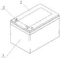
Sequence number in figure: 1 is that battery container, 2 is that upper cover, 3 is that binding post, 4 is that pole plate assembled unit, 5 is that positive plate, 6 is that negative plate, 7 is to be that lug, 9 is that bus-bar, 10 is lead block every cardboard, 8.
Embodiment
Below in conjunction with accompanying drawing, embodiment of the present utility model is elaborated.
Referring to Fig. 1-4, a kind of polar plate of lead acid storage battery short distance combining structure, comprise battery container 1, upper cover 2 and binding post 3, described battery container 1 inside is provided with several pole plate assembled units 4, series connection successively between pole plate assembled unit 4, pole plate assembled unit 4 is 2*3 matrix and arranges, described pole plate assembled unit 4 comprises positive plate 5, negative plate 6 and for isolate positive plate 5 and negative plate 6 every cardboard 7, positive plate 5 and negative plate 6 are arranged in order, the lug 8 of positive plate 5 and negative plate 6 be separately positioned on pole plate assembled unit 4 upper ends a left side, right both sides, the lug 8 of positive plate 5 is all connected by bus-bar 9 with the lug 8 of negative plate 6, on bus-bar 9, all automatic cast welding has lead block 10, between two neighboring pole plate assembled unit 4, by lead block 10, connect, lead block 10 in the pole plate assembled unit 4 of all series connection on the bus-bar 9 of the positive plate 5 of front and back end is connected with binding post 3 with the lead block 10 on the bus-bar 9 of negative plate 6.Described positive plate 5 and the lug 8 of negative plate 6 are arranged on the upper side of pole plate body, the side of the side of lug 8 and pole plate body is connected smoothly on same straight line or by circular arc, described lead block 10 by automatic cast welding be arranged on bus-bar 9 directly over, described lead block 10 is the truncated cone, up-small and down-big with conveniently stripped.
Claims (4)
1. a polar plate of lead acid storage battery short distance combining structure, comprise battery container, upper cover and binding post, described battery container inside is provided with several pole plate assembled units, series connection successively between pole plate assembled unit, it is characterized in that, described pole plate assembled unit comprises positive plate, negative plate and for isolate positive plate and negative plate every cardboard, positive plate and negative plate are arranged in order, the lug of positive plate and negative plate is separately positioned on a left side for pole plate assembled unit, right both sides, the lug of positive plate is all connected by bus-bar with the lug of negative plate, on bus-bar, all automatic cast welding has lead block, between two neighboring pole plate assembled unit, by lead block, connect, lead block on lead block in the pole plate assembled unit of all series connection on the bus-bar of the positive plate of front and back end and the bus-bar of negative plate is connected with binding post.
2. polar plate of lead acid storage battery short distance combining structure according to claim 1, it is characterized in that, described positive plate and the lug of negative plate are arranged on the upper side of pole plate body, and the side of lug side and pole plate body is connected smoothly on same straight line or by circular arc.
3. polar plate of lead acid storage battery short distance combining structure according to claim 1, is characterized in that, described lead block by automatic cast welding be arranged on bus-bar directly over.
4. polar plate of lead acid storage battery short distance combining structure according to claim 1, is characterized in that, described lead block is the truncated cone, up-small and down-big with conveniently stripped.
Priority Applications (1)
| Application Number | Priority Date | Filing Date | Title |
|---|---|---|---|
| CN201320600458.1U CN203536499U (en) | 2013-09-27 | 2013-09-27 | Short-distance combined structure for electrode plates of lead-acid storage battery |
Applications Claiming Priority (1)
| Application Number | Priority Date | Filing Date | Title |
|---|---|---|---|
| CN201320600458.1U CN203536499U (en) | 2013-09-27 | 2013-09-27 | Short-distance combined structure for electrode plates of lead-acid storage battery |
Publications (1)
| Publication Number | Publication Date |
|---|---|
| CN203536499U true CN203536499U (en) | 2014-04-09 |
Family
ID=50422676
Family Applications (1)
| Application Number | Title | Priority Date | Filing Date |
|---|---|---|---|
| CN201320600458.1U Expired - Lifetime CN203536499U (en) | 2013-09-27 | 2013-09-27 | Short-distance combined structure for electrode plates of lead-acid storage battery |
Country Status (1)
| Country | Link |
|---|---|
| CN (1) | CN203536499U (en) |
Cited By (2)
| Publication number | Priority date | Publication date | Assignee | Title |
|---|---|---|---|---|
| CN106025159A (en) * | 2016-06-28 | 2016-10-12 | 天能电池集团(安徽)有限公司 | Lead-acid battery busbar made of non-lead material and lead-acid battery with busbar |
| CN108630875A (en) * | 2017-03-21 | 2018-10-09 | 株式会社东芝 | Secondary cell, battery pack and vehicle |
-
2013
- 2013-09-27 CN CN201320600458.1U patent/CN203536499U/en not_active Expired - Lifetime
Cited By (3)
| Publication number | Priority date | Publication date | Assignee | Title |
|---|---|---|---|---|
| CN106025159A (en) * | 2016-06-28 | 2016-10-12 | 天能电池集团(安徽)有限公司 | Lead-acid battery busbar made of non-lead material and lead-acid battery with busbar |
| CN106025159B (en) * | 2016-06-28 | 2018-06-29 | 天能电池集团(安徽)有限公司 | The lead-acid battery bus-bar that non-lead material makes and the lead-acid battery containing the bus-bar |
| CN108630875A (en) * | 2017-03-21 | 2018-10-09 | 株式会社东芝 | Secondary cell, battery pack and vehicle |
Similar Documents
| Publication | Publication Date | Title |
|---|---|---|
| CN201791951U (en) | Burning-in mold for pole group of battery | |
| CN202178343U (en) | Unpaired weldment plumbic acid battery pack | |
| CN203536499U (en) | Short-distance combined structure for electrode plates of lead-acid storage battery | |
| CN204271173U (en) | A kind of bus-bar supporting power brick high-power applications | |
| CN203932227U (en) | A kind of lithium ion battery | |
| CN101894947B (en) | Outer-conducting encapsulating type accumulator plate | |
| CN203746976U (en) | Lead-acid storage battery grid structure for electric bicycle | |
| CN102274953A (en) | Cast welding mould for storage battery | |
| CN207183372U (en) | A kind of solar street light li-ion cell protection board connecting structure | |
| CN202207792U (en) | Cast welding die for storage battery | |
| CN203707252U (en) | Lead-acid storage battery grid | |
| CN204118192U (en) | Double-pole lug secondary battery | |
| CN202839822U (en) | Valve control sealing type lead-acid storage battery gap bridge connecting structure | |
| CN203787526U (en) | Triangular prism lead-acid storage battery | |
| CN203339252U (en) | Assembling structure for battery cores of flexible package lithium ion battery | |
| CN202917566U (en) | Laminated busbar for connection of high-capacity power lithium batteries | |
| CN203521536U (en) | Novel flexible packaging lithium-ion power battery | |
| CN201936938U (en) | Multi-functional comb die for welding pole groups of lead-acid accumulator | |
| CN202940290U (en) | Electric motorcar lead acid storage battery structure provided with offset pole lugs | |
| CN203536522U (en) | Long-life start-stop battery grid | |
| CN203345149U (en) | Electric bicycle battery box allowing multiple batteries to be installed | |
| CN202804147U (en) | Multi-station cast-welding bottom die for battery of electric bicycle | |
| CN202996951U (en) | Welding structure of polar group of storage battery | |
| CN201450066U (en) | Storage battery with balanced charge-discharge device | |
| CN206961246U (en) | A kind of coin-feed shares charger baby |
Legal Events
| Date | Code | Title | Description |
|---|---|---|---|
| C14 | Grant of patent or utility model | ||
| GR01 | Patent grant | ||
| CX01 | Expiry of patent term | ||
| CX01 | Expiry of patent term |
Granted publication date: 20140409 |