EP3379278A1 - Batterieenergiespeicher - Google Patents
Batterieenergiespeicher Download PDFInfo
- Publication number
- EP3379278A1 EP3379278A1 EP17161785.5A EP17161785A EP3379278A1 EP 3379278 A1 EP3379278 A1 EP 3379278A1 EP 17161785 A EP17161785 A EP 17161785A EP 3379278 A1 EP3379278 A1 EP 3379278A1
- Authority
- EP
- European Patent Office
- Prior art keywords
- energy store
- battery energy
- soc
- battery
- parameters
- Prior art date
- Legal status (The legal status is an assumption and is not a legal conclusion. Google has not performed a legal analysis and makes no representation as to the accuracy of the status listed.)
- Withdrawn
Links
Images


Classifications
-
- G—PHYSICS
- G01—MEASURING; TESTING
- G01R—MEASURING ELECTRIC VARIABLES; MEASURING MAGNETIC VARIABLES
- G01R31/00—Arrangements for testing electric properties; Arrangements for locating electric faults; Arrangements for electrical testing characterised by what is being tested not provided for elsewhere
- G01R31/36—Arrangements for testing, measuring or monitoring the electrical condition of accumulators or electric batteries, e.g. capacity or state of charge [SoC]
- G01R31/396—Acquisition or processing of data for testing or for monitoring individual cells or groups of cells within a battery
-
- B—PERFORMING OPERATIONS; TRANSPORTING
- B60—VEHICLES IN GENERAL
- B60L—PROPULSION OF ELECTRICALLY-PROPELLED VEHICLES; SUPPLYING ELECTRIC POWER FOR AUXILIARY EQUIPMENT OF ELECTRICALLY-PROPELLED VEHICLES; ELECTRODYNAMIC BRAKE SYSTEMS FOR VEHICLES IN GENERAL; MAGNETIC SUSPENSION OR LEVITATION FOR VEHICLES; MONITORING OPERATING VARIABLES OF ELECTRICALLY-PROPELLED VEHICLES; ELECTRIC SAFETY DEVICES FOR ELECTRICALLY-PROPELLED VEHICLES
- B60L58/00—Methods or circuit arrangements for monitoring or controlling batteries or fuel cells, specially adapted for electric vehicles
- B60L58/10—Methods or circuit arrangements for monitoring or controlling batteries or fuel cells, specially adapted for electric vehicles for monitoring or controlling batteries
- B60L58/12—Methods or circuit arrangements for monitoring or controlling batteries or fuel cells, specially adapted for electric vehicles for monitoring or controlling batteries responding to state of charge [SoC]
-
- G—PHYSICS
- G01—MEASURING; TESTING
- G01R—MEASURING ELECTRIC VARIABLES; MEASURING MAGNETIC VARIABLES
- G01R31/00—Arrangements for testing electric properties; Arrangements for locating electric faults; Arrangements for electrical testing characterised by what is being tested not provided for elsewhere
- G01R31/36—Arrangements for testing, measuring or monitoring the electrical condition of accumulators or electric batteries, e.g. capacity or state of charge [SoC]
- G01R31/367—Software therefor, e.g. for battery testing using modelling or look-up tables
-
- G—PHYSICS
- G01—MEASURING; TESTING
- G01R—MEASURING ELECTRIC VARIABLES; MEASURING MAGNETIC VARIABLES
- G01R31/00—Arrangements for testing electric properties; Arrangements for locating electric faults; Arrangements for electrical testing characterised by what is being tested not provided for elsewhere
- G01R31/36—Arrangements for testing, measuring or monitoring the electrical condition of accumulators or electric batteries, e.g. capacity or state of charge [SoC]
- G01R31/374—Arrangements for testing, measuring or monitoring the electrical condition of accumulators or electric batteries, e.g. capacity or state of charge [SoC] with means for correcting the measurement for temperature or ageing
-
- G—PHYSICS
- G01—MEASURING; TESTING
- G01R—MEASURING ELECTRIC VARIABLES; MEASURING MAGNETIC VARIABLES
- G01R31/00—Arrangements for testing electric properties; Arrangements for locating electric faults; Arrangements for electrical testing characterised by what is being tested not provided for elsewhere
- G01R31/36—Arrangements for testing, measuring or monitoring the electrical condition of accumulators or electric batteries, e.g. capacity or state of charge [SoC]
- G01R31/382—Arrangements for monitoring battery or accumulator variables, e.g. SoC
- G01R31/3842—Arrangements for monitoring battery or accumulator variables, e.g. SoC combining voltage and current measurements
-
- G—PHYSICS
- G01—MEASURING; TESTING
- G01R—MEASURING ELECTRIC VARIABLES; MEASURING MAGNETIC VARIABLES
- G01R31/00—Arrangements for testing electric properties; Arrangements for locating electric faults; Arrangements for electrical testing characterised by what is being tested not provided for elsewhere
- G01R31/36—Arrangements for testing, measuring or monitoring the electrical condition of accumulators or electric batteries, e.g. capacity or state of charge [SoC]
- G01R31/385—Arrangements for measuring battery or accumulator variables
- G01R31/387—Determining ampere-hour charge capacity or SoC
-
- G—PHYSICS
- G01—MEASURING; TESTING
- G01R—MEASURING ELECTRIC VARIABLES; MEASURING MAGNETIC VARIABLES
- G01R31/00—Arrangements for testing electric properties; Arrangements for locating electric faults; Arrangements for electrical testing characterised by what is being tested not provided for elsewhere
- G01R31/36—Arrangements for testing, measuring or monitoring the electrical condition of accumulators or electric batteries, e.g. capacity or state of charge [SoC]
- G01R31/389—Measuring internal impedance, internal conductance or related variables
-
- Y—GENERAL TAGGING OF NEW TECHNOLOGICAL DEVELOPMENTS; GENERAL TAGGING OF CROSS-SECTIONAL TECHNOLOGIES SPANNING OVER SEVERAL SECTIONS OF THE IPC; TECHNICAL SUBJECTS COVERED BY FORMER USPC CROSS-REFERENCE ART COLLECTIONS [XRACs] AND DIGESTS
- Y02—TECHNOLOGIES OR APPLICATIONS FOR MITIGATION OR ADAPTATION AGAINST CLIMATE CHANGE
- Y02T—CLIMATE CHANGE MITIGATION TECHNOLOGIES RELATED TO TRANSPORTATION
- Y02T10/00—Road transport of goods or passengers
- Y02T10/60—Other road transportation technologies with climate change mitigation effect
- Y02T10/70—Energy storage systems for electromobility, e.g. batteries
Definitions
- the invention relates to enable dynamic evaluation of performance of a battery energy store, and a system thereof.
- BESS Battery Energy Storage Systems
- a Battery Management System estimates two main parameters, i.e. the state of charge (SOC) and the state of health (SOH) for the battery. Since the SOC cannot be measured directly, various methods are used to determine its value, the most common one being the current integration (or Coulomb counting), where the SOC is calculated by measuring the battery current and integrating it in time. However, since all measurements include errors, this method suffers from long-term drift and lack of a reference point. Thus, the SOC must be re-calibrated on a regular basis, which might not be convenient in a real-life demanding application. The SOH calculation depends on the performance requirements of each specific application and depends on a good estimation of the remaining capacity.
- SOC state of charge
- SOH state of health
- An object of the invention is to enable fast identification of possible critical degradation of a battery energy storage system.
- a method for enabling dynamic evaluation of performance of a battery energy storage comprises measuring real-time parameters of a battery energy store, estimating a state of charge for the battery energy store, the estimation being based on the measured real-time parameters and off-line data of the energy store, identification of R-C parameters for an equivalent circuit model of the battery energy store, the identification being based on the measured real-time parameters, updating a look-up table with the identified R-C parameters for different operating conditions, and simulating performance of the battery energy store based on two or more operating conditions.
- the battery energy store may be used to operate a marine vessel, such as propelling or positioning the marine vessel.
- the battery energy store may be a battery energy store system (BESS).
- BESS battery energy store system
- the method may further comprise estimating a hybrid SOC parameter based on the estimated SOC and a SOC calculation.
- the estimated SOC and the SOC calculation may be combined weighted with a time parameter, such that for an older battery energy store the estimated SOC are more relevant than the calculated SOC, and for a newer battery energy store the calculated SOC is more relevant than the estimated SOC.
- the battery energy store may comprise a plurality of batteries
- the method may further comprise excitation of the battery energy store, including increasing a current charge/discharge for one or more of the plurality of batteries, and decreasing a current charge/discharge for one or more of the plurality of batteries, wherein a total current charge/discharge for the plurality of batteries is kept unchanged.
- the method may comprise comparing the total current before and after the excitation of the battery energy store to estimate SOC.
- a system for enabling dynamic evaluation of performance of a battery energy store comprises a battery energy store, a real-time measurement module for measuring real-time parameters of the battery energy store, an off-line data module for storing off-line data of the battery energy store, a state of charge estimation module for estimation of the SOC of the battery energy store, wherein the estimation being based on measured real-time parameters and off-line data of the energy store, an identification module, wherein R-C parameters for an equivalent circuit model of the battery energy store are identified, the identification being based on the measured real-time parameters, an update module for updating a look-up table with the identified R-C parameters for different operating conditions, and a simulation module for performance simulation of the battery energy store based on two or more operating conditions.
- a marine vessel is also presented.
- a computer program product for enabling dynamic evaluation of performance of a battery energy store.
- the computer program product comprises computer program code stored on a computer readable storage means, the computer program code, when run on a system, causes the system to measure real-time parameters of a battery energy store, estimate a state of charge for the battery energy store, the estimation being based on the measured real-time parameters and off-line data of the energy store, identify of R-C parameters for an equivalent circuit model of the battery energy store, the identification being based on the measured real-time parameters, update a look-up table with the identified R-C parameters for different operating conditions, and simulate performance of the battery energy store based on two or more operating conditions.
- the benefits of dynamically evaluating the BESS performance can be summarized as: optimize the battery operation, operate the battery in a safe operating range, identify degradation of the battery in a timely manner, and ensure performance of battery for a specific time period.
- the goal of the proposed system is to dynamically evaluate the performance of a BESS in order to ensure the safe and optimal operation for a specific period of time fulfilling the expected performance requirements for a specific application.
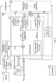
- the system includes at least one battery, or a battery module, or a battery rack or a complete BESS 1, a measurement system with sensors, transducers and communication channels to transfer the real-time measurements 2, a computer device 3, which receives real-time inputs from the measurement system and off-line data 4 and uses them to perform a combination of algorithms in order to estimate the SOC, capacity and parameters of the ECM, a second computer device 5 which receives the previous estimations and data regarding the load of the battery 6 and performs calculations to dynamically, update the capacity and the ECM of the battery and continuous simulations to update the SOH and perform an early diagnosis in case of critical degradation of the battery.
- the battery 1 represents a generic BESS, where a number of battery cells are connected in parallel and series configuration forming battery modules and racks and controlled by one or more BMS.
- the real-time measurement system 2 takes measurements, including voltage (V), current (I) and temperature (T), from one or more battery cells/modules/racks and transmits them to the computer device for further processing.
- V voltage
- I current
- T temperature
- the computer device 3 has input/output units to receive data from the measurement system and from offline databases, memory where the computer software and the data are stored and processing power to execute the computer software, which includes the combination of ECM parameter estimation, SOC estimation, and capacity estimation algorithms.
- the off-line data 4 may come from other databases and can include the OCV vs. SOC curve of the battery as provided from the manufacturer, look-up tables, nominal characteristics of the battery, etc.
- the second computer device 5 receives the estimations performed from the first computer software, real-time measurements from the measurement system and also data regarding the performance requirements from the load profile of the battery, and performs data analyses, simulations of the battery operation, calculations and updates on the ECM and the capacity and other functions.
- the objective of these functions are to optimize the operation of the battery ensuring that it can fulfil the load requirements, to update the battery model parameters for various voltage and temperature operational regions and to timely diagnose undesired conditions, due to degradation or abnormal operation of the battery.
- the load data 6 may be actual real-time load values, historical data of load profile, or forecasts, or stochastic data, or synthetic load profiles or other load scenarios or combinations of the above.
- This block receives the values of the ECM parameters (resistances and capacitances) as calculated from a real-time parameter identification and comparing them with their initial values decides if and when to update the ECM. Then it sends the updated model back to module 3.
- This block receives the value of the battery capacity as estimated from the real-time capacity estimation and comparing it with its initial value and taking into account the time period that has elapsed decides if and when to update it. Then it sends the updated capacity back to module 3, replacing the initial nominal capacity.
- the ECM models a battery using an R-C electrical circuit, with a number of resistances and capacitances connected in series and in parallel.
- the values of these parameters are ideally independent from the current flowing through the battery, thus the electrical equivalent. However, in reality they can be dependent on the charge/discharge current.
- module 5 This can be mainly attributed to their dependence on the battery temperature, especially the instantaneous series resistance, which varies according to the current. Therefore, one more function inside module 5 is dedicated into creating, and constantly updating, look-up tables for the R-C parameters of the ECM for different operating regions, i.e. different temperatures and currents.
- This block receives inputs from module 6, which provides different kind of load data, and performs various statistical analyses. It can create statistics for example about max and min load values, frequency and duration of cycles, identification of load patterns, depth of discharge requirements, power and energy requirements, etc. Based on the type of battery and on the performance requirements for a given time period, the block creates a number of possible worst-case scenarios in order to feed the simulation block.
- the worst-case scenario(s) are a static set of load profiles defined by the system requirement specification. In that case this block may just feed these static worst case load profiles to the "simulation block", without additional analysis on the data received by module 6.
- This block receives the updated ECM and the updated value for the capacity. It also receives load data statistics, worst-case scenarios, different load patterns, etc. from the previous block. Finally, it can take into account the look-up tables that have been created inside the corresponding block (even if they are partially complete).
- Fig. 2 illustrates worst case worst-case scenario simulations on a BESS that is within the safe operation range (left) and on one that is outside the safe operation range due to reduced capacity and higher impedance (right).
- the curves represent measured/estimated values on the physical system.
- BESS Voltage (V) and Temperature (T) depend on both the remaining BESS capacity and the voltage drop due to impedance.
- Fig. 2 illustrate worst-case scenario simulations on a BESS that is within the safe operation range (right) and on one that is outside the safe operation range due to reduced capacity and higher impedance (left).
- the BESS that is outside the safe operation region may be an aged BESS with reduced capacity and higher internal impedance.
- the State of Health (SOH) of the battery is updated.
- SOH State of Health
- the simulation of the BESS In case the simulation of the BESS produces any abnormal results, it can create various alarm signals. This block receives such signals and performs an analysis of the results in order to diagnose any issues with the BESS. These issues could be for example the detection of an unusually high value of the internal resistance of a battery cell, a big change in SOH, a sudden decrease in the capacity of the battery, etc. Also, when simulating worst case operation scenarios an alarm can be given if the projected performance of the BESS cannot meet the defined technical requirements specification.
- the block can inform the user of the diagnostic results and based on a set of guidelines for troubleshooting, suggest a number of remedial actions.
- An embodiment is presented on alternative ways to combine a number of SOC estimation methods with the well-known Coulomb Counting (current integration), in order to increase the accuracy of SOC estimation for an on-line system.
- the combinations of these methods will provide a more robust solution for different types of batteries, different condition of the same battery, different charging/discharging profiles, and different operating regions.
- the benefits of a more accurate state estimation of the battery can be summarized as: optimize the battery operation, operate the battery in a safe operating range, and ensure performance of battery for a specific time period.
- a system where the SOC and the capacity of an operating battery are estimated on-line, using real-time measurements.
- the parameters of an ECM of the battery are also identified.
- the system includes: at least one battery 1, or battery module, or battery rack or complete BESS and their corresponding BMS, power converters, and controls a measurement system 2 with sensors, transducers and communication channels to transfer the real-time measurements, a computer device 3, which receives real-time inputs from the measurement system and off-line data 4 and uses them to perform a combination of algorithms in order to estimate the SOC, capacity and parameters of the ECM, a second computer device 5 which receives the previous estimations and data regarding the load of the battery 6 and performs calculations to optimize the battery performance
- the module 3, particularly subsystem 3a, which performs the SOC estimation is present in more detail.
- the addition of the Coulomb Counting (CC) method for calculating the SOC and the combination of this with the SOC Estimation algorithms is provided in order to provide hybrid methods for improved SOC estimation.
- Module 1 represents one or more BESS, where each BESS consists of a number of battery cells connected in parallel and series configuration forming battery modules and racks and controlled by one or more BMS.
- the power electronic converters used to charge/discharge the batteries are included this module.
- the real-time measurement system 2 takes measurements, including voltage, current and temperature, from one or more battery cells/modules/racks and transmits them to the computer device for further processing.
- the computer device 3 has input/output units to receive data from the measurement system and from offline databases, memory where the computer software and the data are stored and processing power to execute the computer software, which includes the combination of ECM parameter estimation, SOC estimation, and capacity estimation algorithms.
- the off-line data 4 may come from other databases and can include the OCV vs SOC curve of the battery as provided from the manufacturer, look-up tables, nominal characteristics of the battery, etc.
- the second computer device 5 receives the estimations performed from the first computer software, real-time measurements from the measurement system and also data regarding the performance requirements from the load profile of the battery, and performs off-line calculations to optimize the operation of the battery and to timely diagnose undesired conditions, due to degradation or abnormal operation of the battery.
- the load data 6 may be actual real-time load values, historical data of load profile, or forecasts, or stochastic data, or synthetic load profiles or other load scenarios or combinations of the above.
- This block receives inputs of voltage and current from the real-time measurement system and possibly also from the off-line data module and performs an on-line identification of the ECM parameters. Its outputs, i.e. values of the resistances and capacitances of the ECM, are then fed to the SOC Estimation algorithms.
- This block uses the value of SOC as estimated by the appropriate blocks and also information from the on-line current measurements and estimates the remaining capacity of the battery.
- This block receives as inputs the parameters of the ECM, and information from the off-line data module and performs model based on-line SOC estimation.
- R-C parameters of the ECM can be received alternatively from two other sources other than the parameter identification block.
- the off-line data module includes look-up tables of those parameters for the specific type of the battery. This can facilitate a quicker and more accurate SOC estimation, based on the fact that for a relative new battery the internal parameters do not change significantly, thus the SOC estimation algorithms can better rely on the provided initial R-C values from a look-up table, avoiding the unavoidable error from the on-line parameter identification methods.
- an alternative option is to receive the updated ECM parameters from module 5.
- the SOC estimation algorithms can rely on updated look-up tables.
- This block performs the well-known CC method to calculate the SOC of the battery. It receives input from the real-time current measurements and by integrating the current it can calculate the SOC. As it has been already mentioned, this method suffers from long-term drift and lack of a reference point. However, with accurate enough current measurements, the CC can calculate the very accurately the SOC for a relative short period of time, i.e. before the unavoidable errors in current measurement accumulate and cause a drift. The output of this SOC calculation will be combined with the SOC estimated by the SOC estimation algorithms.
- This block receives as an input the real-time current measurement from the real-time measurement block, in order to calculate an appropriate excitation index.
- the value of the index depends on the level of excitation for the specific battery and load profile. This index is fed into the Hybrid SOC Estimation Method 1 and is used to define the weighting factors for the method.
- This block includes one hybrid SOC estimation method, based on a combination of CC and model-based on-line estimation algorithms with different weighting factors.
- the block receives as an input one SOC estimation (SOC_a) from the SOC Estimation Algorithms block and another SOC estimation (SOC_b) from the SOC Calculation with CC block. It also, receives as an input an excitation index as calculated from the Calculate Excitation Index block.
- the output of this block is a SOC estimation (SOC1) based on either a) the CC in case the index indicates a very low value of excitation, or b) the model-based SOC estimation algorithms in case the value of the index indicates a high enough excitation or c) a combination of these two SOC estimation with appropriate weighting factors attached to each of them in case the index indicates intermediate excitation conditions.
- SOC1 SOC estimation
- the SOC estimated from the last model-based estimation is taken as initial value of the SOC, avoiding the lack of reference point that is associated with CC method in general.
- SOC_a and SOC_b there are numerous ways to combine SOC_a and SOC_b, e.g. weighted average, etc.
- This block includes another hybrid SOC estimation method, based on a continuous on-line correction of the CC method with estimations from model-based algorithms.
- This correction is based on the fact that the CC method (that gives the SOC_b) is capable of very accurately monitoring the change of SOC in the short term (assuming accurate enough current measurements), but can eventually suffer from poor initialization and a drift in the long term.
- the model-based estimation algorithms do not show any drift and can in general estimate the average SOC very accurately. However during low excitation the model-based estimation algorithms might lose their accuracy. Thus, the combined SOC estimation is more robust in the long term.
- This method can be implemented using various correction processes, and below two examples are presented.
- the inputs for the hybrid estimation method 2 block are the SOC_a and SOC_b, as described above and the OCV-SOC curve from the Offline data module 4.
- the method receives the two on-line SOC estimations and stores their values for a period of time as time-series SOC_a(t) and SOC_b(t). Then in predefined time instances it calculates the average or mean value of each SOC estimation for a given time window [ti, t2]. It then compares these values avg(SOC_a(t)) and avg(SOC_b(t)) and if their difference is higher than a predefined limit a correction process is triggered. This process aims at correcting the SOC estimation by removing a possible erroneous offset of the SOC_b using the average value of SOC_a. In the general case t2 could be equal to ti.
- the inputs for the hybrid estimation method 2 block are again the SOC_a and SOC_b and the OCV-SOC curve from the Off-line data module 4.
- the method calculates in each time t the difference between SOC_a(t) and SOC_b(t) and uses this value as an error, which is fed to a controller, PI or similar.
- the output of the controller is a correction factor which is then added to the output of the SOC_b. This provides a continuous correction of the drifting of SOC_b, while at the same time avoids the real-time errors of SOC_a due to low observability.
- CBatt is the capacity of the battery in Ah and IBatt the real-time current measurement (in sec).
- Hybrid SOC Estimation method 2 An example of the implementation of Hybrid SOC Estimation method 2 is illustrated in Fig. 4 .
- the third input of this block i.e. the OCV-SOC curve
- the OCV-SOC curve can be used in order to identify the high non-linear regions of this curve, where the model-based estimation tends to be less accurate. This might be useful in case for example the model-based estimation is actually accurate enough so that it can be used alone.
- the hybrid method 2 may be implemented only for some difficult operating regions of the SOC.
- the final SOC output of module 3 can be either SOCi, as estimated by the Hybrid estimation method 1, or SOC2, as estimated by the Hybrid estimation method 2, depending on the specific requirements and operating conditions.
- the problem is that, for an on-line monitoring system, the accuracy of the parameter identification and the state estimation algorithms depends heavily on the quality or observability of the real-time measurements data.
- quality not only the accuracy of the measurements, but also their sampling frequency and their rate of change, are meant, all of which affect the information that can be extracted.
- An embodiment of methods presented herein is to increase the observability of the on-line system, so that the parameter identification and the state estimation algorithms will be able to provide accurate estimation, even in cases that the real-time measurement data, in their original form, might not be able to provide enough/suitable information to the algorithms to achieve the needed state estimation accuracy.
- the benefits of a more accurate state estimation and a dynamically updated ECM of the battery can be summarized as: optimize the battery operation, operate the battery in a safe operating range, identify degradation of the battery in a timely manner, ensure performance of battery for a specific time period.
- a system where the SOC and the capacity of an operating battery are estimated on-line, using real-time measurements.
- the parameters of an ECM of the battery are also identified.
- the system includes at least one battery, or battery module, or battery rack or complete BESS and their corresponding BMS, power converters, and controls 1, a measurement system 2 with sensors, transducers and communication channels to transfer the real-time measurements, a computer device 3, which receives real-time inputs from the measurement system and off-line data 4 and uses them to perform a combination of algorithms in order to estimate the SOC, capacity and parameters of the ECM, a second computer device 5 which receives the previous estimations and data regarding the load of the battery 6 and performs calculations to optimize the battery performance .
- a measurement system 2 with sensors, transducers and communication channels to transfer the real-time measurements
- a computer device 3 which receives real-time inputs from the measurement system and off-line data 4 and uses them to perform a combination of algorithms in order to estimate the SOC, capacity and parameters of the ECM
- a second computer device 5 which receives the previous estimations and data regarding the load of the battery 6 and performs calculations to optimize the battery performance .
- the focus of this embodiment is in the part of the system, which is responsible to enhance the observability of the BESS real-time monitoring, in order to be able to achieve accurate on-line estimations of the SOC and the capacity of an operating BESS, as well as accurate parameter identification of the ECM of the battery. This is included in module 1 in Fig. 5 .
- Module 1 represents one or more BESS, where each BESS consists of a number of battery cells connected in parallel and series configuration forming battery modules and racks and controlled by one or more BMS.
- the power electronic converters used to charge/discharge the batteries are included in this module.
- the proposed system for enhancing the observability for better estimation is also included in this module, and will be explained in the next section.
- the real-time measurement system 2 takes measurements, including voltage, current and (optionally) temperature, from one or more battery cells/modules/racks and transmits them to the computer device for further processing.
- the computer device 3 has input/output units to receive data from the measurement system and from offline databases, memory where the computer software and the data are stored and processing power to execute the computer software, which includes the combination of ECM parameter estimation, SOC estimation, and capacity estimation algorithms.
- the off-line data 4 may come from other databases and can include the OCV vs. SOC curve of the battery as provided from the manufacturer, look-up tables, nominal characteristics of the battery, etc.
- the second computer device 5 receives the estimations performed from the first computer software, real-time measurements from the measurement system and also data regarding the performance requirements from the load profile of the battery, and performs off-line calculations to optimize the operation of the battery and to timely diagnose undesired conditions, due to degradation or abnormal operation of the battery.
- the load data 6 may be actual real-time load values, historical data of load profile, or forecasts, or stochastic data, or synthetic load profiles or other load scenarios or combinations of the above.
- Module 1 may contain any number N of battery blocks, where N is at least one.
- Each of these blocks may be either a battery module, consisted of a number of battery cells connected in series and parallel configuration, or a battery rack (parallel/series connected modules) or a BESS (parallel/series connected battery racks).
- Each of these "batteries” is monitored and controlled by each own BMS.
- Each battery block has its own dedicated power conversion system. This can be any kind of dc/dc or dc/ac converter, which is used to charge and discharge the battery accordingly in order to meet the load requirements.
- This block takes high resolution real-time measurements of voltage and current. These measurements may be necessary in case the sampling frequency of the real-time measurement system 2 is not high enough to provide appropriate information for an accurate parameter identification (especially for the instantaneous resistance).
- module 3 which performs this estimation, sends a signal to request high resolution measurements. These high resolution measurements can be collected in two ways.
- the SOC and/or capacity estimation algorithms require a certain level of excitation in their input in order to be able to give accurate estimations. For example, if the battery is charging for a long time with constant current, the on-line algorithms might lose the ability to estimate correctly the SOC, since the excitation (rate of change of current) might not contain enough information to properly estimate resistance and hence OCV and SOC. In that case, module 3 can send a request for enhanced observability to module 1. Then, the "Enhanced Excitation Control System" will answer to that request by properly changing the charge/discharge current of at least one of the batteries, while at the same time adjusting the current of the rest of the batteries, in order to retain the total current flowing in/out of the BESS unchanged.
- Fig. 6 a simple example for a BESS with two batteries is illustrated.
- the total load current is defined from the application and the Battery 1 and 2 current curves are the current as distributed into the two batteries. After a period of charging with a ramping current there is a relative long period of constant current, where the estimation algorithms lack excitation to perform a good estimation.
- module 3 requests for an enhanced observability and the enhanced excitation control system responds by forcing the excitation into battery 1 with a current pulse. At the same time the system reduces the current in battery 2, so that the total current during this forced excitation period remains the same for the load.
- the total BESS comprises at least two different batteries, as depicted by the Battery block in Fig. 5 .
- Fig. 7 An alternative way to increase the observability is presented, which is done in the level of the Battery module, i.e. one level down from the power conversion system.
- the enhanced excitation control system sends a control signal to the battery, instead of the Power Conversion System (PCS).
- PCS Power Conversion System
- the system controls the opening/closing of at least one of the DC contactors that connect the battery racks to the common DC bus that goes to the PCS.
- the DC contactors may be mechanical contactors/breakers or static switches or a combination thereof.
- a test has been performed, connecting an LFP battery cell to a PEC battery cell tester, and loading it with a specific charging/discharging profile. Voltage and current are measured by the PEC tester with very high accuracy. The current is also internally integrated with high accuracy (millisecond range), producing an accurate on-line measurement of the SOC, which will be used as the reference to compare with the SOC estimation given by our algorithms.
- Fig. 8 measurements of the current that was used to test the battery and the respective voltage response are illustrated.
- the battery starts at around 60% SOC level and is being discharged/charged between 30-35% and 60% continuously using ramping down/up and constant current.
- the first five cycles do not have any forced excitation, while the last five cycles include one short current pulse during each constant current charge/discharge and each ramping down current.
- These forced current pulses have been introduced in order to investigate if and how much does the observability change, thus the SOC estimation, as well.
- Fig. 9 the SOC estimation performed in module 3 and also the real SOC based on accurate current integration form the test equipment.
- Fig. 10 the absolute error (in %) of the SOC estimation is illustrated.
Landscapes
- Engineering & Computer Science (AREA)
- Physics & Mathematics (AREA)
- General Physics & Mathematics (AREA)
- Life Sciences & Earth Sciences (AREA)
- Sustainable Development (AREA)
- Sustainable Energy (AREA)
- Power Engineering (AREA)
- Transportation (AREA)
- Mechanical Engineering (AREA)
- Secondary Cells (AREA)
- Charge And Discharge Circuits For Batteries Or The Like (AREA)
Priority Applications (2)
| Application Number | Priority Date | Filing Date | Title |
|---|---|---|---|
| EP17161785.5A EP3379278A1 (de) | 2017-03-20 | 2017-03-20 | Batterieenergiespeicher |
| PCT/EP2018/056700 WO2018172216A1 (en) | 2017-03-20 | 2018-03-16 | Battery energy store |
Applications Claiming Priority (1)
| Application Number | Priority Date | Filing Date | Title |
|---|---|---|---|
| EP17161785.5A EP3379278A1 (de) | 2017-03-20 | 2017-03-20 | Batterieenergiespeicher |
Publications (1)
| Publication Number | Publication Date |
|---|---|
| EP3379278A1 true EP3379278A1 (de) | 2018-09-26 |
Family
ID=58387727
Family Applications (1)
| Application Number | Title | Priority Date | Filing Date |
|---|---|---|---|
| EP17161785.5A Withdrawn EP3379278A1 (de) | 2017-03-20 | 2017-03-20 | Batterieenergiespeicher |
Country Status (2)
| Country | Link |
|---|---|
| EP (1) | EP3379278A1 (de) |
| WO (1) | WO2018172216A1 (de) |
Cited By (8)
| Publication number | Priority date | Publication date | Assignee | Title |
|---|---|---|---|---|
| CN109325299A (zh) * | 2018-09-29 | 2019-02-12 | 大连理工大学 | 一种全钒液流电池的复合建模仿真方法 |
| CN109710583A (zh) * | 2018-12-28 | 2019-05-03 | 上海仁童电子科技有限公司 | Simulink模型中的参数自动更新方法及装置 |
| WO2020153866A1 (en) * | 2019-01-24 | 2020-07-30 | Siemens Aktiengesellschaft | Method and system for monitoring a battery state using a battery twin |
| CN112946487A (zh) * | 2021-05-17 | 2021-06-11 | 杭州华塑科技股份有限公司 | 一种参数辨识方法、装置、存储介质及计算机设备 |
| EP4011683A3 (de) * | 2020-10-21 | 2022-08-31 | Yamaha Hatsudoki Kabushiki Kaisha | Seeschiffstromversorgungssystem, seeschiff und seeschiffstromversorgungsverfahren |
| DE102021211870A1 (de) | 2021-10-21 | 2023-04-27 | Robert Bosch Gesellschaft mit beschränkter Haftung | Verfahren zum Überwachen eines Energiespeichers in einem Kraftfahrzeug |
| US11912388B2 (en) | 2020-10-21 | 2024-02-27 | Yamaha Hatsudoki Kabushiki Kaisha | Marine vessel power supply system, and marine vessel |
| US11999261B2 (en) | 2019-01-24 | 2024-06-04 | Siemens Aktiengesellschaft | Method and system for monitoring a battery state utilizing a battery twin |
Families Citing this family (3)
| Publication number | Priority date | Publication date | Assignee | Title |
|---|---|---|---|---|
| US10666076B1 (en) * | 2018-08-14 | 2020-05-26 | Veritone Alpha, Inc. | Using battery state excitation to control battery operations |
| CN112836174B (zh) * | 2020-12-31 | 2023-06-09 | 深圳市加码能源科技有限公司 | 一种基于ahp的实时充电安全评估方法及存储介质 |
| DE102022129314A1 (de) * | 2022-11-07 | 2024-05-08 | Hochschule Offenburg, Körperschaft des öffentlichen Rechts | Verfahren und Vorrichtung zur Bestimmung von Kapazität, Innenwiderstand und Leerlaufspannungskurve einer Batterie |
Citations (5)
| Publication number | Priority date | Publication date | Assignee | Title |
|---|---|---|---|---|
| US20040162683A1 (en) * | 2003-02-18 | 2004-08-19 | Verbrugge Mark W. | Method and apparatus for generalized recursive least-squares process for battery state of charge and state of health |
| US20060284600A1 (en) * | 2005-06-21 | 2006-12-21 | Verbrugge Mark W | Method for control and monitoring using a state estimator having variable forgetting factors |
| US20110309838A1 (en) * | 2010-06-22 | 2011-12-22 | Gm Global Technology Operations, Inc. | Adaptive battery parameter extraction and soc estimation for lithium-ion battery |
| EP2597479A2 (de) * | 2011-11-25 | 2013-05-29 | Honeywell International Inc. | Verfahren und Vorrichtung zur Online-Bestimmung des Ladezustands und des Alterungszustands einer Batterie |
| EP2700964A2 (de) * | 2012-08-24 | 2014-02-26 | Hitachi Vehicle Energy, Ltd. | Batteriezustandsschätzungssystem, Batteriesteuersystem, Batteriesystem, und Verfahren zur Schätzung des Batteriezustands |
Family Cites Families (1)
| Publication number | Priority date | Publication date | Assignee | Title |
|---|---|---|---|---|
| JP5679738B2 (ja) * | 2010-08-26 | 2015-03-04 | 株式会社日立製作所 | 電池制御装置及びこの電池制御装置を搭載した車両システム |
-
2017
- 2017-03-20 EP EP17161785.5A patent/EP3379278A1/de not_active Withdrawn
-
2018
- 2018-03-16 WO PCT/EP2018/056700 patent/WO2018172216A1/en active Application Filing
Patent Citations (5)
| Publication number | Priority date | Publication date | Assignee | Title |
|---|---|---|---|---|
| US20040162683A1 (en) * | 2003-02-18 | 2004-08-19 | Verbrugge Mark W. | Method and apparatus for generalized recursive least-squares process for battery state of charge and state of health |
| US20060284600A1 (en) * | 2005-06-21 | 2006-12-21 | Verbrugge Mark W | Method for control and monitoring using a state estimator having variable forgetting factors |
| US20110309838A1 (en) * | 2010-06-22 | 2011-12-22 | Gm Global Technology Operations, Inc. | Adaptive battery parameter extraction and soc estimation for lithium-ion battery |
| EP2597479A2 (de) * | 2011-11-25 | 2013-05-29 | Honeywell International Inc. | Verfahren und Vorrichtung zur Online-Bestimmung des Ladezustands und des Alterungszustands einer Batterie |
| EP2700964A2 (de) * | 2012-08-24 | 2014-02-26 | Hitachi Vehicle Energy, Ltd. | Batteriezustandsschätzungssystem, Batteriesteuersystem, Batteriesystem, und Verfahren zur Schätzung des Batteriezustands |
Cited By (10)
| Publication number | Priority date | Publication date | Assignee | Title |
|---|---|---|---|---|
| CN109325299A (zh) * | 2018-09-29 | 2019-02-12 | 大连理工大学 | 一种全钒液流电池的复合建模仿真方法 |
| CN109325299B (zh) * | 2018-09-29 | 2022-10-04 | 大连理工大学 | 一种全钒液流电池的复合建模仿真方法 |
| CN109710583A (zh) * | 2018-12-28 | 2019-05-03 | 上海仁童电子科技有限公司 | Simulink模型中的参数自动更新方法及装置 |
| WO2020153866A1 (en) * | 2019-01-24 | 2020-07-30 | Siemens Aktiengesellschaft | Method and system for monitoring a battery state using a battery twin |
| US11999261B2 (en) | 2019-01-24 | 2024-06-04 | Siemens Aktiengesellschaft | Method and system for monitoring a battery state utilizing a battery twin |
| EP4011683A3 (de) * | 2020-10-21 | 2022-08-31 | Yamaha Hatsudoki Kabushiki Kaisha | Seeschiffstromversorgungssystem, seeschiff und seeschiffstromversorgungsverfahren |
| US11912388B2 (en) | 2020-10-21 | 2024-02-27 | Yamaha Hatsudoki Kabushiki Kaisha | Marine vessel power supply system, and marine vessel |
| CN112946487A (zh) * | 2021-05-17 | 2021-06-11 | 杭州华塑科技股份有限公司 | 一种参数辨识方法、装置、存储介质及计算机设备 |
| CN112946487B (zh) * | 2021-05-17 | 2021-08-03 | 杭州华塑科技股份有限公司 | 一种参数辨识方法、装置、存储介质及计算机设备 |
| DE102021211870A1 (de) | 2021-10-21 | 2023-04-27 | Robert Bosch Gesellschaft mit beschränkter Haftung | Verfahren zum Überwachen eines Energiespeichers in einem Kraftfahrzeug |
Also Published As
| Publication number | Publication date |
|---|---|
| WO2018172216A1 (en) | 2018-09-27 |
Similar Documents
| Publication | Publication Date | Title |
|---|---|---|
| EP3379278A1 (de) | Batterieenergiespeicher | |
| US11221367B2 (en) | Evaluation device, energy storage system, evaluation method and non-transitory computer readable medium | |
| KR102200550B1 (ko) | 이차 전지의 충전 상태를 추정하기 위한 장치 | |
| JP5442583B2 (ja) | 電源装置用状態検知装置及び電源装置 | |
| EP2851700B1 (de) | Verfahren und endgerät zur anzeige der kapazität einer batterie | |
| US6388450B2 (en) | Method for determining the state of charge of storage batteries | |
| KR20160146032A (ko) | 배터리의 상태를 추정하는 장치 및 방법 | |
| EP2827162A1 (de) | Gleichstromimpedanzmessung in Batterie | |
| CN108205114B (zh) | 电池寿命的预测方法及系统 | |
| EP3171187A1 (de) | Batteriezustandserfassungsvorrichtung, sekundärbatteriesystem, programmprodukt und batteriezustandserfassungsverfahren | |
| US20220179003A1 (en) | Characterisation of lithium plating in rechargeable batteries | |
| EP3171186A1 (de) | Batteriezustandserfassungsvorrichtung, sekundärbatteriesystem, programmprodukt und batteriezustandserfassungsverfahren | |
| JP7292404B2 (ja) | バッテリ健全状態の推定方法 | |
| WO2009025512A2 (en) | System and method for estimating long term characteristics of battery | |
| EP2206191A2 (de) | System und verfahren zur schätzung von langzeiteigenschaften einer batterie | |
| EP3832331B1 (de) | Zellzustandschätzungsvorrichtung und zellsteuerungsvorrichtung | |
| Bockrath et al. | State of charge estimation using recurrent neural networks with long short-term memory for lithium-ion batteries | |
| JPWO2017056732A1 (ja) | 電池制御装置及び電池システム | |
| Zhu et al. | The SOH estimation of LiFePO4 battery based on internal resistance with Grey Markov Chain | |
| CN114464906A (zh) | 动力电池预警方法和装置 | |
| CN204030697U (zh) | 基于动态soc估算系统的电池管理系统 | |
| Camci et al. | Sampling based State of Health estimation methodology for Li-ion batteries | |
| Tripathy et al. | State-of-Charge estimation algorithms and their implications on cells in parallel | |
| JP6470318B2 (ja) | 蓄電池装置、及び内部抵抗値導出方法 | |
| US20230213587A1 (en) | Method and System for Efficiently Monitoring Battery Cells of a Device Battery in an External Central Processing Unit Using a Digital Twin |
Legal Events
| Date | Code | Title | Description |
|---|---|---|---|
| PUAI | Public reference made under article 153(3) epc to a published international application that has entered the european phase |
Free format text: ORIGINAL CODE: 0009012 |
|
| AK | Designated contracting states |
Kind code of ref document: A1 Designated state(s): AL AT BE BG CH CY CZ DE DK EE ES FI FR GB GR HR HU IE IS IT LI LT LU LV MC MK MT NL NO PL PT RO RS SE SI SK SM TR |
|
| AX | Request for extension of the european patent |
Extension state: BA ME |
|
| STAA | Information on the status of an ep patent application or granted ep patent |
Free format text: STATUS: THE APPLICATION IS DEEMED TO BE WITHDRAWN |
|
| 18D | Application deemed to be withdrawn |
Effective date: 20190327 |