EP3379206A1 - Rotation detection device - Google Patents
Rotation detection device Download PDFInfo
- Publication number
- EP3379206A1 EP3379206A1 EP16866062.9A EP16866062A EP3379206A1 EP 3379206 A1 EP3379206 A1 EP 3379206A1 EP 16866062 A EP16866062 A EP 16866062A EP 3379206 A1 EP3379206 A1 EP 3379206A1
- Authority
- EP
- European Patent Office
- Prior art keywords
- housing
- case
- detection device
- detection element
- rotation detection
- Prior art date
- Legal status (The legal status is an assumption and is not a legal conclusion. Google has not performed a legal analysis and makes no representation as to the accuracy of the status listed.)
- Granted
Links
Images



Classifications
-
- G—PHYSICS
- G01—MEASURING; TESTING
- G01D—MEASURING NOT SPECIALLY ADAPTED FOR A SPECIFIC VARIABLE; ARRANGEMENTS FOR MEASURING TWO OR MORE VARIABLES NOT COVERED IN A SINGLE OTHER SUBCLASS; TARIFF METERING APPARATUS; MEASURING OR TESTING NOT OTHERWISE PROVIDED FOR
- G01D5/00—Mechanical means for transferring the output of a sensing member; Means for converting the output of a sensing member to another variable where the form or nature of the sensing member does not constrain the means for converting; Transducers not specially adapted for a specific variable
- G01D5/12—Mechanical means for transferring the output of a sensing member; Means for converting the output of a sensing member to another variable where the form or nature of the sensing member does not constrain the means for converting; Transducers not specially adapted for a specific variable using electric or magnetic means
- G01D5/244—Mechanical means for transferring the output of a sensing member; Means for converting the output of a sensing member to another variable where the form or nature of the sensing member does not constrain the means for converting; Transducers not specially adapted for a specific variable using electric or magnetic means influencing characteristics of pulses or pulse trains; generating pulses or pulse trains
- G01D5/245—Mechanical means for transferring the output of a sensing member; Means for converting the output of a sensing member to another variable where the form or nature of the sensing member does not constrain the means for converting; Transducers not specially adapted for a specific variable using electric or magnetic means influencing characteristics of pulses or pulse trains; generating pulses or pulse trains using a variable number of pulses in a train
-
- G—PHYSICS
- G01—MEASURING; TESTING
- G01P—MEASURING LINEAR OR ANGULAR SPEED, ACCELERATION, DECELERATION, OR SHOCK; INDICATING PRESENCE, ABSENCE, OR DIRECTION, OF MOVEMENT
- G01P1/00—Details of instruments
- G01P1/02—Housings
- G01P1/026—Housings for speed measuring devices, e.g. pulse generator
-
- G—PHYSICS
- G01—MEASURING; TESTING
- G01D—MEASURING NOT SPECIALLY ADAPTED FOR A SPECIFIC VARIABLE; ARRANGEMENTS FOR MEASURING TWO OR MORE VARIABLES NOT COVERED IN A SINGLE OTHER SUBCLASS; TARIFF METERING APPARATUS; MEASURING OR TESTING NOT OTHERWISE PROVIDED FOR
- G01D11/00—Component parts of measuring arrangements not specially adapted for a specific variable
- G01D11/24—Housings ; Casings for instruments
- G01D11/245—Housings for sensors
-
- G—PHYSICS
- G01—MEASURING; TESTING
- G01P—MEASURING LINEAR OR ANGULAR SPEED, ACCELERATION, DECELERATION, OR SHOCK; INDICATING PRESENCE, ABSENCE, OR DIRECTION, OF MOVEMENT
- G01P3/00—Measuring linear or angular speed; Measuring differences of linear or angular speeds
- G01P3/42—Devices characterised by the use of electric or magnetic means
- G01P3/44—Devices characterised by the use of electric or magnetic means for measuring angular speed
- G01P3/48—Devices characterised by the use of electric or magnetic means for measuring angular speed by measuring frequency of generated current or voltage
- G01P3/481—Devices characterised by the use of electric or magnetic means for measuring angular speed by measuring frequency of generated current or voltage of pulse signals
- G01P3/488—Devices characterised by the use of electric or magnetic means for measuring angular speed by measuring frequency of generated current or voltage of pulse signals delivered by variable reluctance detectors
-
- G—PHYSICS
- G01—MEASURING; TESTING
- G01D—MEASURING NOT SPECIALLY ADAPTED FOR A SPECIFIC VARIABLE; ARRANGEMENTS FOR MEASURING TWO OR MORE VARIABLES NOT COVERED IN A SINGLE OTHER SUBCLASS; TARIFF METERING APPARATUS; MEASURING OR TESTING NOT OTHERWISE PROVIDED FOR
- G01D5/00—Mechanical means for transferring the output of a sensing member; Means for converting the output of a sensing member to another variable where the form or nature of the sensing member does not constrain the means for converting; Transducers not specially adapted for a specific variable
- G01D5/12—Mechanical means for transferring the output of a sensing member; Means for converting the output of a sensing member to another variable where the form or nature of the sensing member does not constrain the means for converting; Transducers not specially adapted for a specific variable using electric or magnetic means
- G01D5/14—Mechanical means for transferring the output of a sensing member; Means for converting the output of a sensing member to another variable where the form or nature of the sensing member does not constrain the means for converting; Transducers not specially adapted for a specific variable using electric or magnetic means influencing the magnitude of a current or voltage
- G01D5/142—Mechanical means for transferring the output of a sensing member; Means for converting the output of a sensing member to another variable where the form or nature of the sensing member does not constrain the means for converting; Transducers not specially adapted for a specific variable using electric or magnetic means influencing the magnitude of a current or voltage using Hall-effect devices
- G01D5/147—Mechanical means for transferring the output of a sensing member; Means for converting the output of a sensing member to another variable where the form or nature of the sensing member does not constrain the means for converting; Transducers not specially adapted for a specific variable using electric or magnetic means influencing the magnitude of a current or voltage using Hall-effect devices influenced by the movement of a third element, the position of Hall device and the source of magnetic field being fixed in respect to each other
Definitions
- the present invention relates to an improved rotation detection device.
- a rotation detection device is disposed, for example, in the vicinity of a wheel shaft of a front wheel of a bicycle. It is possible to measure a traveling speed of the bicycle from a rotation speed of the front wheel, which is detected by the rotation detection device.
- One of conventional technologies that are relevant to such rotation detection device is a technology disclosed in Patent Literature Document 1.
- the rotation detection device such as the device disclosed in Patent Literature Document 1, has a cylindrical case, a magnetism detection element disposed at a bottom portion of the case, and a magnet disposed at the bottom portion of the case. Resin is loaded into the case such that the magnetism detection element and the magnet are embedded in the case.
- Parts and components such as the magnetism detection element are fixed by the loaded resin in the case. It is possible to reduce the possibility that the parts and components such as the magnetism detection element are displaced in the case due to vibrations, and improve the detection accuracy.
- Patent Literature Document 1 Japanese Patent Application Laid-Open Publication No. 2008-164439
- An object of the present invention is to provide a rotation detection device that can be manufactured in a short(er) period of time.
- a rotation detection device that includes a magnetism detection element that detects a change in magnetism produced as a rotating body rotates, a magnet that applies a magnetic field to the magnetism detection element, a lead terminal connected to the magnetism detection element, and a housing that houses the magnetism detection element, the magnet, and the lead terminal, the magnetism detection element, the magnet, and the lead terminal are mounted on an inner case
- the housing includes a first housing having a connection portion that can be connected to an external connector and a second housing fitted in the first housing and disposed to face the rotating body, and the first housing or the second housing is provided with an inner-case fitting portion into which the inner case is fitted.
- the inner-case fitting portion has a cylindrical shape
- a sealing member is mounted on an outer periphery of the inner-case fitting portion, and the sealing member is held between the first housing and the second housing.
- the first housing has a first-housing bottom plate and a first-housing peripheral wall that extends from an entire periphery of the first-housing bottom plate toward the second housing, and the second housing is covered by the first-housing bottom plate and the first-housing peripheral wall.
- one of the first housing and the second housing is provided with an engagement claw, and the other of the first housing and the second housing is provided with an engagement hole that can engage with the engagement claw.
- the inner case on which the magnetism detection element, the magnet, and the lead terminal are mounted is fitted in the inner-case fitting portion provided in the first housing or the second housing. Parts and components, such as the magnetism detection element, are fixed to the inner-case fitting portion with the inner case interposed therebetween.
- This configuration can suppress displacement that could be caused by vibrations.
- This configuration does not need the loading of resin to suppress displacement of parts and components, such as the magnetism detection element. Therefore, the time for curing the resin is unnecessary, and it is possible to provide the rotation detection device that can be manufactured in a shorter period of time.
- the sealing member is mounted on the outer periphery of the cylindrical inner-case fitting portion, and the sealing member is held between the first housing and the second housing. Entry of water into the interior from the outside is suppressed at the outer periphery of the inner-case fitting portion, and the lifetime of the rotation detection device can be extended.
- the second housing is covered by the first-housing bottom plate and the first-housing peripheral wall.
- first-housing peripheral wall When water present outside the rotation detection device is to enter the interior of the housing, the water needs to pass between the first-housing peripheral wall and the second housing and also between the first-housing bottom plate and the second housing.
- the presence of the first-housing peripheral wall increases the distance to reach the interior of the housing. This suppresses entry of water into the interior of the housing and can extend the lifetime of the rotation detection device.
- one of the first housing and the second housing is provided with the engagement claw, and the other of the first housing and the second housing is provided with the engagement hole that can engage with the engagement claw.
- a rotation detection device 10 is provided, for example, in the vicinity of a wheel shaft (axle) of a front wheel of a two-wheeled vehicle or bicycle.
- the travelling speed of the two-wheeled vehicle can be measured on the basis of a rotation speed of the front wheel detected by the rotation detection device 10.
- a portion depicted at the upper center in Fig. 1 is attached to a vehicle body, and a portion depicted to the right in Fig. 1 is connected to an external connector.
- a portion depicted to the left in Fig. 1 is disposed to oppose the wheel shaft.
- the rotation detection device 10 includes a magnetism detection element 11 that detects a change in magnetism, a magnet 12 that applies (imparts) a magnetic field to the magnetism detection element 11, and lead terminals 13 connected to the magnetism detection element 11.
- the magnetism detection element 11, the magnet 12, and the lead terminals 13 are mounted on an inner case 20, which is then housed in a housing 30.
- the housing 30 has a sealing member 17 for suppressing entry of water into the interior of the housing 30.
- a cylindrical collar 18 is mounted to the housing 30.
- a bolt is inserted into the collar 18.
- the housing 30 includes a first housing 40 and a second housing 50 fitted into the first housing 40 and disposed to oppose a rotating body.
- the first housing 40 and the second housing 50 are each a resin molded product. Any desired resin, such as polybutylene terephthalate resin, can be used as a material for the first housing 40 and the second housing 50.
- the magnetism detection element 11 has a detection element main body 11a disposed adjacent to the magnet 12 and element-side contacts 11b and 11b that extend downward from a lower portion of the detection element main body 11a and are in contact with the lead terminals 13 and 13.
- the element-side contacts 11b and 11b are formed at two positions to match the number of the lead terminals 13 and 13.
- the lead terminals 13 and 13 each have a generally L shape.
- the lead terminals 13 and 13 have terminal main bodies 13a and 13a that extend along a lower surface of the inner case 20 and terminal-side contacts 13b and 13b that extend downward from one ends of the respective terminal main bodies 13a and 13a and are in contact with the element-side contacts 11b and 11b.
- Two terminal holes 13c for fixing the lead terminals 13 and 13 to the inner case 20 are formed in each of the terminal main bodies 13a and 13a.
- the inner case 20 includes a case main body 21 that houses the magnetism detection element 11 and the magnet 12, case ribs 22 and 22 formed on the right and left sides of the case main body 21 to reinforce the case main body 21, a case abutment portion 23 that extends from a leading end of the case main body 21 toward the first housing 40 and has a leading end that abuts the first housing 40, and case pins 24 and 24 that extend downward from a lower surface of the case main body 21 and are inserted in the terminal holes 13c.
- the case pins 24 and 24 are formed integrally with the case main body 21.
- Any desired resin such as polybutylene terephthalate resin, can be used as a material for the inner case 20.
- the first housing 40 includes a first-housing bottom plate 41, a first-housing peripheral wall 42 that extends from an entire periphery of the first-housing bottom plate 41 toward the second housing 50, an inner-case fitting portion 43 that extends from the first-housing bottom plate 41 toward the second housing 50 in an area surrounded by the first-housing peripheral wall 42, and a connection portion 44 that is formed on the first-housing bottom plate 41 and can be connected to an external connector.
- the second housing 50 includes a second-housing base 51 covered by the first-housing bottom plate 41 and the first-housing peripheral wall 42, a cylindrical second-housing intermediate portion 52 formed integrally with the second-housing base 51, and a cylindrical rotating-body opposing portion 53 that is formed integrally with the second-housing intermediate portion 52 and has a closed bottom.
- first-housing bottom plate 41 Formed in the first-housing bottom plate 41 are a first collar insertion hole 41a in which the collar 18 is inserted and terminal insertion holes 41b that provide communication between the inner-case fitting portion 43 and the connection portion 44 and in which the lead terminals 13 are inserted.
- Engagement holes 42a that engage with the second housing 50 are formed at four positions in the first-housing peripheral wall 42.
- the inner-case fitting portion 43 is in connection with the connection portion 44 with the first-housing bottom plate 41 interposed therebetween.
- the inner-case fitting portion 43 and the connection portion 44 are provided on the first-housing bottom plate 41 at the same location.
- the inner-case fitting portion 43 extends from the first-housing bottom plate 41 toward the second housing 50, and the connection portion 44 extends from the first-housing bottom plate 41, serving as a starting point, away from the second housing 50.
- a housing hole Ho for housing the inner case 20 is formed continuously in the second-housing base 51, the second-housing intermediate portion 52, and the rotating-body opposing portion 53.
- the outer wall of the housing hole Ho can be regarded as a peripheral wall that surrounds the inner case 20.
- the portion formed in the second-housing base 51 can be regarded as a base peripheral wall 51a.
- the base peripheral wall 51a is formed in a circular shape along the outer surface of the cylindrical inner-case fitting portion 43.
- a groove 51b that surrounds the base peripheral wall 51a is formed in the second-housing base 51.
- the groove 51b is formed to oppose the first housing 40 (first-housing bottom plate 41).
- Engagement claws 51c that engage with the engagement holes 42a in the first housing 40 and second collar insertion hole 51d in which the collar 18 is inserted are formed in the second-housing base 51.
- An O-ring made of acrylic rubber or silicone rubber can be employed as the sealing member 17.
- inner-case fitting portion 43 may be formed in the second housing 50. Also, the inner-case fitting portion 43 may be formed in both the first housing 40 and the second housing 50.
- the engagement claws 51c may be provided on the first housing 40. In this configuration, the engagement holes 42a are provided in the second housing 50.
- the magnetism detection element 11 and the magnet 12 are housed into the inner-case main body 21, and the lead terminals 13 are fixed to the lower surface of the inner-case main body 21.
- the case pins 24 are inserted into the terminal holes 13c, and the lead terminals 13 are then fused and attached to the inner-case main body 21.
- the sealing member 17 is mounted to the outer periphery of the inner-case fitting portion 43.
- the magnetism detection element 11, the magnet 12, and the lead terminals 13 are mounted onto the inner case 20, and this assembly is press-fitted into the inner-case fitting portion 43. As the assembly is fitted into the inner-case fitting portion 43, the leading ends of the lead terminals 13 face the interior of the connection portion 44.
- sealing member 17 and the collar 18 can be mounted at desired timings.
- the inner case 20 on which the magnetism detection element 11, the magnet 12, and the lead terminals 13 are mounted is fitted in the inner-case fitting portion 43 provided in the first housing 40.
- Parts and components, such as the magnetism detection element 11, are fixed to the inner-case fitting portion 43 with the inner case 20 interposed therebetween.
- This configuration can suppress displacement that could be caused by vibrations.
- This configuration can render resin loading unnecessary to suppress displacement of parts and components, such as the magnetism detection element 11. Therefore, the time for curing resin becomes unnecessary, and it is possible to provide the rotation detection device 10 that can be manufactured in a shorter period of time.
- the sealing member 17 is mounted on the outer periphery of the cylinder inner-case fitting portion 43, and the sealing member 17 is held between the first housing 40 and the second housing 50. Entry of water into the interior from the outside is suppressed at the outer periphery of the inner-case fitting portion 43, and the lifetime of the rotation detection device 10 can be extended.
- the second housing 50 is covered by the first-housing bottom plate 41 and the first-housing peripheral wall 42.
- first-housing peripheral wall 42 When water present outside the rotation detection device 10 is to enter the interior of the housing 30, the water needs to pass between the first-housing peripheral wall 42 and the second housing 50 and also between the first-housing bottom plate 41 and the second housing 50.
- the presence of the first-housing peripheral wall 42 increases the distance to reach the interior of the housing 30. This suppresses entry of water into the interior of the housing 30 and can extend the lifetime of the rotation detection device 10.
- the base peripheral wall 51a is formed in the second housing 50 along the outer periphery of the inner-case fitting portion 43, and the groove 51b is formed to surround the base peripheral wall 51a.
- the base peripheral wall 51a and the inner-case fitting portion 43 hold the sealing member 17 therebetween.
- the groove 51b is formed around the sealing member 17. The groove 51b can suppress entry of water into the interior of the housing 30. Therefore, it is possible to suppress entry of water into the interior of the housing 30 and extend the lifetime of the rotation detection device 10.
- the engagement claws 51c are provided on the second housing 50, and the engagement holes 42a that can engage with the engagement claws 51c are provided in the first housing 40. This simplifies the mounting of the second housing 50 onto the first housing 40 and can further reduce the time for manufacturing the rotation detection device 10.
- the inner case 20 includes the case main body 21 on which the magnetism detection element 11 is mounted and the case ribs 22 and 22 that are formed integrally with the case main body 21 to reinforce the case main body 21.
- the inner case 20 has a width L1.
- the inner-case fitting portion 43 has a cylindrical shape.
- the inner-case fitting portion 43 has an inner diameter L2.
- the width L1 of the inner case 20 is approximately equal to the inner diameter L2 of the inner-case fitting portion 43, and the inner diameter L2 of the inner-case fitting portion 43 is slightly larger than the width L1 of the inner case 20. Therefore, the case ribs 22 and 22 make contact with the inner peripheral surface of the inner-case fitting portion 43.
- the case ribs 22 and 22 abut the inner peripheral surface of the inner-case fitting portion 43.
- the case ribs 22 and 22 abut the inner-case fitting portion 43, displacement of the inner case 20 inside the housing 30 is suppressed.
- Displacement of the inner case 20 is suppressed by the case ribs 22 and 22 provided to reinforce the case main body 21. Displacement of the inner case 20 can be suppressed with a small number of components and with a simple configuration, which is desirable.
- FIG. 7(a) and 7(b) illustrate a modified example of the inner-case fitting portion shown in Fig. 6 .
- the case ribs 22 and 22 are formed integrally with the case main body 21 at the right and left sides thereof and each have a rectangular parallelepiped shape.
- An inner-case fitting portion 43A includes protrusions 43a that protrude toward the case ribs 22 and 22 and have respective leading ends that abut the case ribs 22 and 22.
- the protrusions 43a each abut a corresponding one of an upper surface, a lower surface, and an outer side surface of the right and left case ribs 22 and 22.
- the protrusions 43a abut the case ribs 22 and 22 at many positions, displacement of the inner case 20 can be suppressed more reliably.
- the protrusions 43a each have a generally V shape (generally triangular shape) in a state in which the inner case 20 is not yet fitted in the inner-case fitting portion 43A.
- the strength of the protrusion 43a is lower than the strength of the case ribs 22 and 22.
- the leading ends of the protrusions 43a are deformed by the case ribs 22 and 22.
- the protrusions 43a abut the case ribs 22 and 22 in an elastically deformed state. This ensures that the protrusions 43a abut the case ribs 22 and 22.
- This configuration also makes it possible to absorb dimension errors produced inevitably among different products.
- the rotation detection device has been described with an example in which the rotation detection device is used on a front wheel of a two-wheeled vehicle, the rotation detection device may be used on a rear wheel, and the present invention is not limited to such embodiments. In other words, the present invention is not limited to the embodiments as long as the functions and the advantageous effects of the present invention are obtained.
- the rotation detection device of the present invention is advantageous to detect a travelling speed of a two-wheeled vehicle.
Landscapes
- Physics & Mathematics (AREA)
- General Physics & Mathematics (AREA)
- Transmission And Conversion Of Sensor Element Output (AREA)
Abstract
Description
- The present invention relates to an improved rotation detection device.
- A rotation detection device is disposed, for example, in the vicinity of a wheel shaft of a front wheel of a bicycle. It is possible to measure a traveling speed of the bicycle from a rotation speed of the front wheel, which is detected by the rotation detection device. One of conventional technologies that are relevant to such rotation detection device is a technology disclosed in Patent Literature Document 1.
- The rotation detection device, such as the device disclosed in Patent Literature Document 1, has a cylindrical case, a magnetism detection element disposed at a bottom portion of the case, and a magnet disposed at the bottom portion of the case. Resin is loaded into the case such that the magnetism detection element and the magnet are embedded in the case.
- Parts and components such as the magnetism detection element are fixed by the loaded resin in the case. It is possible to reduce the possibility that the parts and components such as the magnetism detection element are displaced in the case due to vibrations, and improve the detection accuracy.
- However, such rotation detection device requires the curing of the loaded resin. Thus, the work time for manufacturing the rotation detection device becomes longer.
- Patent Literature Document 1: Japanese Patent Application Laid-Open Publication No.
2008-164439 - An object of the present invention is to provide a rotation detection device that can be manufactured in a short(er) period of time.
- According to an aspect of the present invention, there is provided a rotation detection device that includes a magnetism detection element that detects a change in magnetism produced as a rotating body rotates, a magnet that applies a magnetic field to the magnetism detection element, a lead terminal connected to the magnetism detection element, and a housing that houses the magnetism detection element, the magnet, and the lead terminal,
the magnetism detection element, the magnet, and the lead terminal are mounted on an inner case,
the housing includes a first housing having a connection portion that can be connected to an external connector and a second housing fitted in the first housing and disposed to face the rotating body, and
the first housing or the second housing is provided with an inner-case fitting portion into which the inner case is fitted. - Preferably, the inner-case fitting portion has a cylindrical shape,
a sealing member is mounted on an outer periphery of the inner-case fitting portion, and
the sealing member is held between the first housing and the second housing. - Preferably, the first housing has a first-housing bottom plate and a first-housing peripheral wall that extends from an entire periphery of the first-housing bottom plate toward the second housing, and
the second housing is covered by the first-housing bottom plate and the first-housing peripheral wall. - Preferably, one of the first housing and the second housing is provided with an engagement claw, and the other of the first housing and the second housing is provided with an engagement hole that can engage with the engagement claw.
- In the present invention, the inner case on which the magnetism detection element, the magnet, and the lead terminal are mounted is fitted in the inner-case fitting portion provided in the first housing or the second housing. Parts and components, such as the magnetism detection element, are fixed to the inner-case fitting portion with the inner case interposed therebetween. This configuration can suppress displacement that could be caused by vibrations. This configuration does not need the loading of resin to suppress displacement of parts and components, such as the magnetism detection element. Therefore, the time for curing the resin is unnecessary, and it is possible to provide the rotation detection device that can be manufactured in a shorter period of time.
- In the present invention, the sealing member is mounted on the outer periphery of the cylindrical inner-case fitting portion, and the sealing member is held between the first housing and the second housing. Entry of water into the interior from the outside is suppressed at the outer periphery of the inner-case fitting portion, and the lifetime of the rotation detection device can be extended.
- In the present invention, the second housing is covered by the first-housing bottom plate and the first-housing peripheral wall. When water present outside the rotation detection device is to enter the interior of the housing, the water needs to pass between the first-housing peripheral wall and the second housing and also between the first-housing bottom plate and the second housing. The presence of the first-housing peripheral wall increases the distance to reach the interior of the housing. This suppresses entry of water into the interior of the housing and can extend the lifetime of the rotation detection device.
- In the present invention, one of the first housing and the second housing is provided with the engagement claw, and the other of the first housing and the second housing is provided with the engagement hole that can engage with the engagement claw. This simplifies the mounting of the second housing onto the first housing and can further reduce the time for manufacturing the rotation detection device. In addition, this configuration can facilitate the removal of the second housing from the first housing. Thus, the rotation detection device with high maintainability can be provided.
-
-
Fig. 1 is a perspective view of a rotation detection device according to an embodiment of the present invention. -
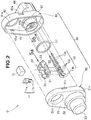
Fig. 2 is an exploded perspective view of the rotation detection device illustrated inFig. 1 . -
Fig. 3 is an exploded cross-sectional view of the rotation detection device illustrated inFig. 2 . -
Fig. 4 is a cross-sectional view taken along the line 4-4 inFig. 1 . -
Fig. 5 is a set of diagrams as viewed in the directions of thearrows Fig. 2 . -
Fig. 6 is a cross-sectional view taken along the line 6-6 inFig. 4 . -
Fig. 7 is a set of views useful to describe a modified example of an inner-case fitting portion illustrated inFig. 6 . - Hereinafter, embodiments of the present invention will be described with reference to the accompanying drawings. In the descriptions, the terms "right" and "left" indicate the right and the left in the drawings, and the terms "up" and "down" indicates the up side and the down side in the drawings.
- Referring to
Fig. 1 , arotation detection device 10 is provided, for example, in the vicinity of a wheel shaft (axle) of a front wheel of a two-wheeled vehicle or bicycle. The travelling speed of the two-wheeled vehicle can be measured on the basis of a rotation speed of the front wheel detected by therotation detection device 10. A portion depicted at the upper center inFig. 1 is attached to a vehicle body, and a portion depicted to the right inFig. 1 is connected to an external connector. A portion depicted to the left inFig. 1 is disposed to oppose the wheel shaft. - Referring to
Fig. 2 , therotation detection device 10 includes amagnetism detection element 11 that detects a change in magnetism, amagnet 12 that applies (imparts) a magnetic field to themagnetism detection element 11, andlead terminals 13 connected to themagnetism detection element 11. Themagnetism detection element 11, themagnet 12, and thelead terminals 13 are mounted on aninner case 20, which is then housed in ahousing 30. Thehousing 30 has a sealingmember 17 for suppressing entry of water into the interior of thehousing 30. - Referring to
Fig. 3 , acylindrical collar 18 is mounted to thehousing 30. When therotation detection device 10 is mounted to a vehicle body or the like, a bolt is inserted into thecollar 18. - The
housing 30 includes afirst housing 40 and asecond housing 50 fitted into thefirst housing 40 and disposed to oppose a rotating body. Thefirst housing 40 and thesecond housing 50 are each a resin molded product. Any desired resin, such as polybutylene terephthalate resin, can be used as a material for thefirst housing 40 and thesecond housing 50. - Referring to
Fig. 2 , themagnetism detection element 11 has a detection elementmain body 11a disposed adjacent to themagnet 12 and element-side contacts main body 11a and are in contact with thelead terminals side contacts lead terminals - Referring also to
Fig. 3 , thelead terminals lead terminals main bodies inner case 20 and terminal-side contacts main bodies side contacts terminal holes 13c for fixing thelead terminals inner case 20 are formed in each of the terminalmain bodies - The
inner case 20 includes a casemain body 21 that houses themagnetism detection element 11 and themagnet 12,case ribs main body 21 to reinforce the casemain body 21, acase abutment portion 23 that extends from a leading end of the casemain body 21 toward thefirst housing 40 and has a leading end that abuts thefirst housing 40, and case pins 24 and 24 that extend downward from a lower surface of the casemain body 21 and are inserted in theterminal holes 13c. The case pins 24 and 24 are formed integrally with the casemain body 21. - Any desired resin, such as polybutylene terephthalate resin, can be used as a material for the
inner case 20. - The
first housing 40 includes a first-housing bottom plate 41, a first-housingperipheral wall 42 that extends from an entire periphery of the first-housing bottom plate 41 toward thesecond housing 50, an inner-casefitting portion 43 that extends from the first-housing bottom plate 41 toward thesecond housing 50 in an area surrounded by the first-housingperipheral wall 42, and aconnection portion 44 that is formed on the first-housing bottom plate 41 and can be connected to an external connector. - The
second housing 50 includes a second-housing base 51 covered by the first-housing bottom plate 41 and the first-housingperipheral wall 42, a cylindrical second-housingintermediate portion 52 formed integrally with the second-housing base 51, and a cylindrical rotating-body opposing portion 53 that is formed integrally with the second-housingintermediate portion 52 and has a closed bottom. - Formed in the first-
housing bottom plate 41 are a firstcollar insertion hole 41a in which thecollar 18 is inserted and terminal insertion holes 41b that provide communication between the inner-casefitting portion 43 and theconnection portion 44 and in which thelead terminals 13 are inserted. -
Engagement holes 42a that engage with thesecond housing 50 are formed at four positions in the first-housingperipheral wall 42. - The inner-case
fitting portion 43 is in connection with theconnection portion 44 with the first-housing bottom plate 41 interposed therebetween. In other words, the inner-casefitting portion 43 and theconnection portion 44 are provided on the first-housing bottom plate 41 at the same location. The inner-casefitting portion 43 extends from the first-housing bottom plate 41 toward thesecond housing 50, and theconnection portion 44 extends from the first-housing bottom plate 41, serving as a starting point, away from thesecond housing 50. - A housing hole Ho for housing the
inner case 20 is formed continuously in the second-housing base 51, the second-housingintermediate portion 52, and the rotating-body opposing portion 53. The outer wall of the housing hole Ho can be regarded as a peripheral wall that surrounds theinner case 20. - Of the peripheral wall, the portion formed in the second-
housing base 51 can be regarded as a baseperipheral wall 51a. The baseperipheral wall 51a is formed in a circular shape along the outer surface of the cylindrical inner-casefitting portion 43. Agroove 51b that surrounds the baseperipheral wall 51a is formed in the second-housing base 51. Thegroove 51b is formed to oppose the first housing 40 (first-housing bottom plate 41). -
Engagement claws 51c that engage with theengagement holes 42a in thefirst housing 40 and secondcollar insertion hole 51d in which thecollar 18 is inserted are formed in the second-housing base 51. - An O-ring made of acrylic rubber or silicone rubber can be employed as the sealing
member 17. - It should be noted that the inner-case
fitting portion 43 may be formed in thesecond housing 50. Also, the inner-casefitting portion 43 may be formed in both thefirst housing 40 and thesecond housing 50. - The
engagement claws 51c may be provided on thefirst housing 40. In this configuration, theengagement holes 42a are provided in thesecond housing 50. - An example of a method of assembling the rotation detection device will be described. Firstly, the
magnetism detection element 11 and themagnet 12 are housed into the inner-casemain body 21, and thelead terminals 13 are fixed to the lower surface of the inner-casemain body 21. The case pins 24 are inserted into theterminal holes 13c, and thelead terminals 13 are then fused and attached to the inner-casemain body 21. - Subsequently, the sealing
member 17 is mounted to the outer periphery of the inner-casefitting portion 43. - Then, the
magnetism detection element 11, themagnet 12, and thelead terminals 13 are mounted onto theinner case 20, and this assembly is press-fitted into the inner-casefitting portion 43. As the assembly is fitted into the inner-casefitting portion 43, the leading ends of thelead terminals 13 face the interior of theconnection portion 44. - Subsequently, the
engagement claws 51c are pushed into theengagement holes 42a to mount thesecond housing 50 into thefirst housing 40. - Lastly, the
collar 18 is inserted into the first and secondcollar insertion holes - It should be noted that the sealing
member 17 and thecollar 18 can be mounted at desired timings. - The above-described rotation detection device according to the embodiment of the present invention provides the following advantageous effects.
- Referring to
Fig. 4 , theinner case 20 on which themagnetism detection element 11, themagnet 12, and thelead terminals 13 are mounted is fitted in the inner-casefitting portion 43 provided in thefirst housing 40. Parts and components, such as themagnetism detection element 11, are fixed to the inner-casefitting portion 43 with theinner case 20 interposed therebetween. This configuration can suppress displacement that could be caused by vibrations. This configuration can render resin loading unnecessary to suppress displacement of parts and components, such as themagnetism detection element 11. Therefore, the time for curing resin becomes unnecessary, and it is possible to provide therotation detection device 10 that can be manufactured in a shorter period of time. - The sealing
member 17 is mounted on the outer periphery of the cylinder inner-casefitting portion 43, and the sealingmember 17 is held between thefirst housing 40 and thesecond housing 50. Entry of water into the interior from the outside is suppressed at the outer periphery of the inner-casefitting portion 43, and the lifetime of therotation detection device 10 can be extended. - The
second housing 50 is covered by the first-housing bottom plate 41 and the first-housingperipheral wall 42. When water present outside therotation detection device 10 is to enter the interior of thehousing 30, the water needs to pass between the first-housingperipheral wall 42 and thesecond housing 50 and also between the first-housing bottom plate 41 and thesecond housing 50. The presence of the first-housingperipheral wall 42 increases the distance to reach the interior of thehousing 30. This suppresses entry of water into the interior of thehousing 30 and can extend the lifetime of therotation detection device 10. - The base
peripheral wall 51a is formed in thesecond housing 50 along the outer periphery of the inner-casefitting portion 43, and thegroove 51b is formed to surround the baseperipheral wall 51a. The baseperipheral wall 51a and the inner-casefitting portion 43 hold the sealingmember 17 therebetween. Thegroove 51b is formed around the sealingmember 17. Thegroove 51b can suppress entry of water into the interior of thehousing 30. Therefore, it is possible to suppress entry of water into the interior of thehousing 30 and extend the lifetime of therotation detection device 10. - Referring to
Fig. 2 , theengagement claws 51c are provided on thesecond housing 50, and theengagement holes 42a that can engage with theengagement claws 51c are provided in thefirst housing 40. This simplifies the mounting of thesecond housing 50 onto thefirst housing 40 and can further reduce the time for manufacturing therotation detection device 10. - Referring to
Fig. 5(a) , theinner case 20 includes the casemain body 21 on which themagnetism detection element 11 is mounted and thecase ribs main body 21 to reinforce the casemain body 21. Theinner case 20 has a width L1. - Referring to
Fig. 5(b) , the inner-casefitting portion 43 has a cylindrical shape. The inner-casefitting portion 43 has an inner diameter L2. - Referring also to
Fig. 5(a) , the width L1 of theinner case 20 is approximately equal to the inner diameter L2 of the inner-casefitting portion 43, and the inner diameter L2 of the inner-casefitting portion 43 is slightly larger than the width L1 of theinner case 20. Therefore, thecase ribs fitting portion 43. - Referring to
Fig. 6 , thecase ribs fitting portion 43. As thecase ribs fitting portion 43, displacement of theinner case 20 inside thehousing 30 is suppressed. Displacement of theinner case 20 is suppressed by thecase ribs main body 21. Displacement of theinner case 20 can be suppressed with a small number of components and with a simple configuration, which is desirable. - Referring to
Figs. 7(a) and 7(b) , these drawings illustrate a modified example of the inner-case fitting portion shown inFig. 6 . Thecase ribs main body 21 at the right and left sides thereof and each have a rectangular parallelepiped shape. An inner-casefitting portion 43A includesprotrusions 43a that protrude toward thecase ribs case ribs protrusions 43a each abut a corresponding one of an upper surface, a lower surface, and an outer side surface of the right and leftcase ribs protrusions 43a abut thecase ribs inner case 20 can be suppressed more reliably. - The
protrusions 43a each have a generally V shape (generally triangular shape) in a state in which theinner case 20 is not yet fitted in the inner-casefitting portion 43A. The strength of theprotrusion 43a is lower than the strength of thecase ribs inner case 20 is fitted into the inner-casefitting portion 43A, the leading ends of theprotrusions 43a are deformed by thecase ribs protrusions 43a abut thecase ribs protrusions 43a abut thecase ribs - Although the rotation detection device according to the embodiment of the present invention has been described with an example in which the rotation detection device is used on a front wheel of a two-wheeled vehicle, the rotation detection device may be used on a rear wheel, and the present invention is not limited to such embodiments. In other words, the present invention is not limited to the embodiments as long as the functions and the advantageous effects of the present invention are obtained.
- The rotation detection device of the present invention is advantageous to detect a travelling speed of a two-wheeled vehicle.
-
- 10 Rotation detection device
- 11 Magnetism detection element
- 12 Magnet
- 13 Lead terminal
- 17 Sealing member
- 20 Inner case
- 30 Housing
- 40 First housing
- 41 Fist-housing bottom plate
- 42 First-housing peripheral wall
- 42a Engagement holes
- 43 Inner-case fitting portion
- 44 Connection portion
- 50 Second housing
- 51c Engagement claws
Claims (4)
- A rotation detection device comprising a magnetism detection element that detects a change in magnetism produced as a rotating body rotates, a magnet that applies a magnetic field to the magnetism detection element, a lead terminal connected to the magnetism detection element, and a housing that houses the magnetism detection element, the magnet, and the lead terminal,
the magnetism detection element, the magnet, and the lead terminal being mounted on an inner case,
the housing including a first housing having a connection portion that can be connected to an external connector and a second housing fitted in the first housing and disposed to face the rotating body, and
the first housing or the second housing being provided with an inner-case fitting portion into which the inner case is fitted. - The rotation detection device according to claim 1, wherein the inner-case fitting portion has a cylindrical shape,
a sealing member is mounted on an outer periphery of the inner-case fitting portion, and
the sealing member is held between the first housing and the second housing. - The rotation detection device according to claim 1 or 2, wherein the first housing has a first-housing bottom plate and a first-housing peripheral wall that extends from an entire periphery of the first-housing bottom plate toward the second housing, and
the second housing is covered by the first-housing bottom plate and the first-housing peripheral wall. - The rotation detection device according to claim 1 or 2, wherein one of the first housing and the second housing is provided with an engagement claw, and the other of the first housing and the second housing is provided with an engagement hole that can engage with the engagement claw.
Applications Claiming Priority (2)
| Application Number | Priority Date | Filing Date | Title |
|---|---|---|---|
| JP2015224066A JP6431466B2 (en) | 2015-11-16 | 2015-11-16 | Rotation detector |
| PCT/JP2016/080115 WO2017086060A1 (en) | 2015-11-16 | 2016-10-11 | Rotation detection device |
Publications (3)
| Publication Number | Publication Date |
|---|---|
| EP3379206A1 true EP3379206A1 (en) | 2018-09-26 |
| EP3379206A4 EP3379206A4 (en) | 2019-05-22 |
| EP3379206B1 EP3379206B1 (en) | 2020-07-15 |
Family
ID=58718745
Family Applications (1)
| Application Number | Title | Priority Date | Filing Date |
|---|---|---|---|
| EP16866062.9A Active EP3379206B1 (en) | 2015-11-16 | 2016-10-11 | Rotation detection device |
Country Status (5)
| Country | Link |
|---|---|
| EP (1) | EP3379206B1 (en) |
| JP (1) | JP6431466B2 (en) |
| CN (1) | CN108351228B (en) |
| BR (1) | BR112018009357B1 (en) |
| WO (1) | WO2017086060A1 (en) |
Family Cites Families (12)
| Publication number | Priority date | Publication date | Assignee | Title |
|---|---|---|---|---|
| JP2789952B2 (en) * | 1992-07-21 | 1998-08-27 | 株式会社村田製作所 | Magnetic sensor module |
| US6064200A (en) * | 1995-07-21 | 2000-05-16 | Matsushita Electric Industrial Co., Ltd. | Magnetic sensor with detection block, connector block and cap/cover |
| JP3484036B2 (en) * | 1997-02-25 | 2004-01-06 | 三菱電機株式会社 | Magnetic sensor |
| JP2001165702A (en) * | 1999-12-10 | 2001-06-22 | Sumitomo Electric Ind Ltd | Magnetic variable detection sensor |
| JP4232771B2 (en) * | 2005-09-30 | 2009-03-04 | 株式会社デンソー | Rotation detector |
| JP2008151727A (en) * | 2006-12-20 | 2008-07-03 | Ntn Corp | Rotation speed detector and wheel bearing device with the detector |
| JP5035746B2 (en) * | 2006-12-28 | 2012-09-26 | 日本精機株式会社 | Rotation detector |
| JP5146901B2 (en) | 2006-12-28 | 2013-02-20 | 日本精機株式会社 | Rotation detector |
| JP2008209197A (en) * | 2007-02-26 | 2008-09-11 | Sumiden Electronics Kk | Rotation detection sensor |
| KR101142740B1 (en) * | 2009-08-03 | 2012-05-07 | 대성전기공업 주식회사 | Non-contact type switching unit detecting neutral range of vehicular gear transmission |
| JP5724106B2 (en) * | 2011-10-27 | 2015-05-27 | タイコエレクトロニクスジャパン合同会社 | Detection sensor manufacturing method, detection sensor, and transmission |
| KR20150073246A (en) * | 2013-12-20 | 2015-07-01 | 현대자동차주식회사 | Switch for sensing gear step |
-
2015
- 2015-11-16 JP JP2015224066A patent/JP6431466B2/en active Active
-
2016
- 2016-10-11 EP EP16866062.9A patent/EP3379206B1/en active Active
- 2016-10-11 CN CN201680065382.3A patent/CN108351228B/en active Active
- 2016-10-11 BR BR112018009357-2A patent/BR112018009357B1/en active IP Right Grant
- 2016-10-11 WO PCT/JP2016/080115 patent/WO2017086060A1/en not_active Ceased
Also Published As
| Publication number | Publication date |
|---|---|
| CN108351228B (en) | 2020-07-17 |
| JP6431466B2 (en) | 2018-11-28 |
| WO2017086060A1 (en) | 2017-05-26 |
| BR112018009357B1 (en) | 2023-01-17 |
| EP3379206B1 (en) | 2020-07-15 |
| JP2017090385A (en) | 2017-05-25 |
| EP3379206A4 (en) | 2019-05-22 |
| BR112018009357A8 (en) | 2019-02-26 |
| BR112018009357A2 (en) | 2018-11-13 |
| CN108351228A (en) | 2018-07-31 |
Similar Documents
| Publication | Publication Date | Title |
|---|---|---|
| US20120306484A1 (en) | Magnetic detection apparatus | |
| EP2485013B1 (en) | Rotation angle detecting device | |
| JP2015503732A (en) | Variable orientation fluid level sensor with optional sloshing guard | |
| JP6015008B2 (en) | Sensor | |
| JP4179083B2 (en) | Rotation detector | |
| US20110273854A1 (en) | Magnetic Field Sensor | |
| EP3379206B1 (en) | Rotation detection device | |
| US10788353B2 (en) | Liquid-surface detection device | |
| US10907988B2 (en) | Rotation sensor having ring-shaped rib | |
| JP6704441B2 (en) | Rotation detector | |
| JP7240595B2 (en) | Moving body detection device and method for manufacturing moving body detection device | |
| US20160178399A1 (en) | Rotation sensor | |
| CN110062887B (en) | Moving object detection device | |
| US9831651B2 (en) | Cable fastening device | |
| JP7157906B2 (en) | Moving body detection device and method for manufacturing moving body detection device | |
| CN104023497A (en) | Electronic control unit for vehicle | |
| KR100975421B1 (en) | Direct Mold Type Position Sensor of Vehicle Seat Track | |
| JP2019056586A (en) | Moving body detector and method for manufacturing moving body detector | |
| JP5605586B2 (en) | Moving body detection device | |
| US10591314B2 (en) | Rotation sensor | |
| JP2019095245A (en) | Mobile body detector | |
| JP2020034357A (en) | Moving body detection device | |
| JP2021076413A (en) | Moving body detector and manufacturing method for moving body detector | |
| JP2019011977A (en) | Rotation angle detection device | |
| WO2015182109A1 (en) | Liquid level detection device |
Legal Events
| Date | Code | Title | Description |
|---|---|---|---|
| STAA | Information on the status of an ep patent application or granted ep patent |
Free format text: STATUS: THE INTERNATIONAL PUBLICATION HAS BEEN MADE |
|
| PUAI | Public reference made under article 153(3) epc to a published international application that has entered the european phase |
Free format text: ORIGINAL CODE: 0009012 |
|
| STAA | Information on the status of an ep patent application or granted ep patent |
Free format text: STATUS: REQUEST FOR EXAMINATION WAS MADE |
|
| 17P | Request for examination filed |
Effective date: 20180417 |
|
| AK | Designated contracting states |
Kind code of ref document: A1 Designated state(s): AL AT BE BG CH CY CZ DE DK EE ES FI FR GB GR HR HU IE IS IT LI LT LU LV MC MK MT NL NO PL PT RO RS SE SI SK SM TR |
|
| AX | Request for extension of the european patent |
Extension state: BA ME |
|
| DAV | Request for validation of the european patent (deleted) | ||
| DAX | Request for extension of the european patent (deleted) | ||
| REG | Reference to a national code |
Ref country code: DE Ref legal event code: R079 Ref document number: 602016040187 Country of ref document: DE Free format text: PREVIOUS MAIN CLASS: G01D0005245000 Ipc: G01D0011240000 |
|
| A4 | Supplementary search report drawn up and despatched |
Effective date: 20190418 |
|
| RIC1 | Information provided on ipc code assigned before grant |
Ipc: G01D 11/24 20060101AFI20190412BHEP Ipc: G01P 1/02 20060101ALI20190412BHEP |
|
| GRAP | Despatch of communication of intention to grant a patent |
Free format text: ORIGINAL CODE: EPIDOSNIGR1 |
|
| STAA | Information on the status of an ep patent application or granted ep patent |
Free format text: STATUS: GRANT OF PATENT IS INTENDED |
|
| INTG | Intention to grant announced |
Effective date: 20200219 |
|
| GRAS | Grant fee paid |
Free format text: ORIGINAL CODE: EPIDOSNIGR3 |
|
| GRAA | (expected) grant |
Free format text: ORIGINAL CODE: 0009210 |
|
| STAA | Information on the status of an ep patent application or granted ep patent |
Free format text: STATUS: THE PATENT HAS BEEN GRANTED |
|
| AK | Designated contracting states |
Kind code of ref document: B1 Designated state(s): AL AT BE BG CH CY CZ DE DK EE ES FI FR GB GR HR HU IE IS IT LI LT LU LV MC MK MT NL NO PL PT RO RS SE SI SK SM TR |
|
| RAP1 | Party data changed (applicant data changed or rights of an application transferred) |
Owner name: HONDA MOTOR COMPANY LIMITED Owner name: NIPPON SEIKI CO., LTD. |
|
| REG | Reference to a national code |
Ref country code: CH Ref legal event code: EP Ref country code: GB Ref legal event code: FG4D |
|
| REG | Reference to a national code |
Ref country code: IE Ref legal event code: FG4D |
|
| REG | Reference to a national code |
Ref country code: DE Ref legal event code: R096 Ref document number: 602016040187 Country of ref document: DE |
|
| REG | Reference to a national code |
Ref country code: AT Ref legal event code: REF Ref document number: 1291521 Country of ref document: AT Kind code of ref document: T Effective date: 20200815 |
|
| REG | Reference to a national code |
Ref country code: LT Ref legal event code: MG4D |
|
| REG | Reference to a national code |
Ref country code: AT Ref legal event code: MK05 Ref document number: 1291521 Country of ref document: AT Kind code of ref document: T Effective date: 20200715 |
|
| REG | Reference to a national code |
Ref country code: NL Ref legal event code: MP Effective date: 20200715 |
|
| PG25 | Lapsed in a contracting state [announced via postgrant information from national office to epo] |
Ref country code: GR Free format text: LAPSE BECAUSE OF FAILURE TO SUBMIT A TRANSLATION OF THE DESCRIPTION OR TO PAY THE FEE WITHIN THE PRESCRIBED TIME-LIMIT Effective date: 20201016 Ref country code: NO Free format text: LAPSE BECAUSE OF FAILURE TO SUBMIT A TRANSLATION OF THE DESCRIPTION OR TO PAY THE FEE WITHIN THE PRESCRIBED TIME-LIMIT Effective date: 20201015 Ref country code: FI Free format text: LAPSE BECAUSE OF FAILURE TO SUBMIT A TRANSLATION OF THE DESCRIPTION OR TO PAY THE FEE WITHIN THE PRESCRIBED TIME-LIMIT Effective date: 20200715 Ref country code: LT Free format text: LAPSE BECAUSE OF FAILURE TO SUBMIT A TRANSLATION OF THE DESCRIPTION OR TO PAY THE FEE WITHIN THE PRESCRIBED TIME-LIMIT Effective date: 20200715 Ref country code: HR Free format text: LAPSE BECAUSE OF FAILURE TO SUBMIT A TRANSLATION OF THE DESCRIPTION OR TO PAY THE FEE WITHIN THE PRESCRIBED TIME-LIMIT Effective date: 20200715 Ref country code: PT Free format text: LAPSE BECAUSE OF FAILURE TO SUBMIT A TRANSLATION OF THE DESCRIPTION OR TO PAY THE FEE WITHIN THE PRESCRIBED TIME-LIMIT Effective date: 20201116 Ref country code: AT Free format text: LAPSE BECAUSE OF FAILURE TO SUBMIT A TRANSLATION OF THE DESCRIPTION OR TO PAY THE FEE WITHIN THE PRESCRIBED TIME-LIMIT Effective date: 20200715 Ref country code: SE Free format text: LAPSE BECAUSE OF FAILURE TO SUBMIT A TRANSLATION OF THE DESCRIPTION OR TO PAY THE FEE WITHIN THE PRESCRIBED TIME-LIMIT Effective date: 20200715 Ref country code: BG Free format text: LAPSE BECAUSE OF FAILURE TO SUBMIT A TRANSLATION OF THE DESCRIPTION OR TO PAY THE FEE WITHIN THE PRESCRIBED TIME-LIMIT Effective date: 20201015 Ref country code: ES Free format text: LAPSE BECAUSE OF FAILURE TO SUBMIT A TRANSLATION OF THE DESCRIPTION OR TO PAY THE FEE WITHIN THE PRESCRIBED TIME-LIMIT Effective date: 20200715 |
|
| PG25 | Lapsed in a contracting state [announced via postgrant information from national office to epo] |
Ref country code: PL Free format text: LAPSE BECAUSE OF FAILURE TO SUBMIT A TRANSLATION OF THE DESCRIPTION OR TO PAY THE FEE WITHIN THE PRESCRIBED TIME-LIMIT Effective date: 20200715 Ref country code: RS Free format text: LAPSE BECAUSE OF FAILURE TO SUBMIT A TRANSLATION OF THE DESCRIPTION OR TO PAY THE FEE WITHIN THE PRESCRIBED TIME-LIMIT Effective date: 20200715 Ref country code: LV Free format text: LAPSE BECAUSE OF FAILURE TO SUBMIT A TRANSLATION OF THE DESCRIPTION OR TO PAY THE FEE WITHIN THE PRESCRIBED TIME-LIMIT Effective date: 20200715 Ref country code: IS Free format text: LAPSE BECAUSE OF FAILURE TO SUBMIT A TRANSLATION OF THE DESCRIPTION OR TO PAY THE FEE WITHIN THE PRESCRIBED TIME-LIMIT Effective date: 20201115 |
|
| PG25 | Lapsed in a contracting state [announced via postgrant information from national office to epo] |
Ref country code: NL Free format text: LAPSE BECAUSE OF FAILURE TO SUBMIT A TRANSLATION OF THE DESCRIPTION OR TO PAY THE FEE WITHIN THE PRESCRIBED TIME-LIMIT Effective date: 20200715 |
|
| REG | Reference to a national code |
Ref country code: DE Ref legal event code: R097 Ref document number: 602016040187 Country of ref document: DE |
|
| PG25 | Lapsed in a contracting state [announced via postgrant information from national office to epo] |
Ref country code: IT Free format text: LAPSE BECAUSE OF FAILURE TO SUBMIT A TRANSLATION OF THE DESCRIPTION OR TO PAY THE FEE WITHIN THE PRESCRIBED TIME-LIMIT Effective date: 20200715 Ref country code: EE Free format text: LAPSE BECAUSE OF FAILURE TO SUBMIT A TRANSLATION OF THE DESCRIPTION OR TO PAY THE FEE WITHIN THE PRESCRIBED TIME-LIMIT Effective date: 20200715 Ref country code: SM Free format text: LAPSE BECAUSE OF FAILURE TO SUBMIT A TRANSLATION OF THE DESCRIPTION OR TO PAY THE FEE WITHIN THE PRESCRIBED TIME-LIMIT Effective date: 20200715 Ref country code: RO Free format text: LAPSE BECAUSE OF FAILURE TO SUBMIT A TRANSLATION OF THE DESCRIPTION OR TO PAY THE FEE WITHIN THE PRESCRIBED TIME-LIMIT Effective date: 20200715 Ref country code: DK Free format text: LAPSE BECAUSE OF FAILURE TO SUBMIT A TRANSLATION OF THE DESCRIPTION OR TO PAY THE FEE WITHIN THE PRESCRIBED TIME-LIMIT Effective date: 20200715 Ref country code: CZ Free format text: LAPSE BECAUSE OF FAILURE TO SUBMIT A TRANSLATION OF THE DESCRIPTION OR TO PAY THE FEE WITHIN THE PRESCRIBED TIME-LIMIT Effective date: 20200715 |
|
| PLBE | No opposition filed within time limit |
Free format text: ORIGINAL CODE: 0009261 |
|
| STAA | Information on the status of an ep patent application or granted ep patent |
Free format text: STATUS: NO OPPOSITION FILED WITHIN TIME LIMIT |
|
| PG25 | Lapsed in a contracting state [announced via postgrant information from national office to epo] |
Ref country code: AL Free format text: LAPSE BECAUSE OF FAILURE TO SUBMIT A TRANSLATION OF THE DESCRIPTION OR TO PAY THE FEE WITHIN THE PRESCRIBED TIME-LIMIT Effective date: 20200715 |
|
| REG | Reference to a national code |
Ref country code: CH Ref legal event code: PL |
|
| 26N | No opposition filed |
Effective date: 20210416 |
|
| GBPC | Gb: european patent ceased through non-payment of renewal fee |
Effective date: 20201015 |
|
| PG25 | Lapsed in a contracting state [announced via postgrant information from national office to epo] |
Ref country code: MC Free format text: LAPSE BECAUSE OF FAILURE TO SUBMIT A TRANSLATION OF THE DESCRIPTION OR TO PAY THE FEE WITHIN THE PRESCRIBED TIME-LIMIT Effective date: 20200715 Ref country code: LU Free format text: LAPSE BECAUSE OF NON-PAYMENT OF DUE FEES Effective date: 20201011 Ref country code: SK Free format text: LAPSE BECAUSE OF FAILURE TO SUBMIT A TRANSLATION OF THE DESCRIPTION OR TO PAY THE FEE WITHIN THE PRESCRIBED TIME-LIMIT Effective date: 20200715 |
|
| REG | Reference to a national code |
Ref country code: BE Ref legal event code: MM Effective date: 20201031 |
|
| PG25 | Lapsed in a contracting state [announced via postgrant information from national office to epo] |
Ref country code: FR Free format text: LAPSE BECAUSE OF NON-PAYMENT OF DUE FEES Effective date: 20201031 |
|
| PG25 | Lapsed in a contracting state [announced via postgrant information from national office to epo] |
Ref country code: CH Free format text: LAPSE BECAUSE OF NON-PAYMENT OF DUE FEES Effective date: 20201031 Ref country code: BE Free format text: LAPSE BECAUSE OF NON-PAYMENT OF DUE FEES Effective date: 20201031 Ref country code: SI Free format text: LAPSE BECAUSE OF FAILURE TO SUBMIT A TRANSLATION OF THE DESCRIPTION OR TO PAY THE FEE WITHIN THE PRESCRIBED TIME-LIMIT Effective date: 20200715 Ref country code: LI Free format text: LAPSE BECAUSE OF NON-PAYMENT OF DUE FEES Effective date: 20201031 Ref country code: GB Free format text: LAPSE BECAUSE OF NON-PAYMENT OF DUE FEES Effective date: 20201015 |
|
| PG25 | Lapsed in a contracting state [announced via postgrant information from national office to epo] |
Ref country code: IE Free format text: LAPSE BECAUSE OF NON-PAYMENT OF DUE FEES Effective date: 20201011 |
|
| PG25 | Lapsed in a contracting state [announced via postgrant information from national office to epo] |
Ref country code: TR Free format text: LAPSE BECAUSE OF FAILURE TO SUBMIT A TRANSLATION OF THE DESCRIPTION OR TO PAY THE FEE WITHIN THE PRESCRIBED TIME-LIMIT Effective date: 20200715 Ref country code: MT Free format text: LAPSE BECAUSE OF FAILURE TO SUBMIT A TRANSLATION OF THE DESCRIPTION OR TO PAY THE FEE WITHIN THE PRESCRIBED TIME-LIMIT Effective date: 20200715 Ref country code: CY Free format text: LAPSE BECAUSE OF FAILURE TO SUBMIT A TRANSLATION OF THE DESCRIPTION OR TO PAY THE FEE WITHIN THE PRESCRIBED TIME-LIMIT Effective date: 20200715 |
|
| PG25 | Lapsed in a contracting state [announced via postgrant information from national office to epo] |
Ref country code: MK Free format text: LAPSE BECAUSE OF FAILURE TO SUBMIT A TRANSLATION OF THE DESCRIPTION OR TO PAY THE FEE WITHIN THE PRESCRIBED TIME-LIMIT Effective date: 20200715 |
|
| PGFP | Annual fee paid to national office [announced via postgrant information from national office to epo] |
Ref country code: DE Payment date: 20251030 Year of fee payment: 10 |