WO2015182109A1 - Liquid level detection device - Google Patents
Liquid level detection device Download PDFInfo
- Publication number
- WO2015182109A1 WO2015182109A1 PCT/JP2015/002631 JP2015002631W WO2015182109A1 WO 2015182109 A1 WO2015182109 A1 WO 2015182109A1 JP 2015002631 W JP2015002631 W JP 2015002631W WO 2015182109 A1 WO2015182109 A1 WO 2015182109A1
- Authority
- WO
- WIPO (PCT)
- Prior art keywords
- fitting
- outer cylinder
- distance
- inner shaft
- engaging portion
- Prior art date
Links
Images


Classifications
-
- G—PHYSICS
- G01—MEASURING; TESTING
- G01F—MEASURING VOLUME, VOLUME FLOW, MASS FLOW OR LIQUID LEVEL; METERING BY VOLUME
- G01F23/00—Indicating or measuring liquid level or level of fluent solid material, e.g. indicating in terms of volume or indicating by means of an alarm
- G01F23/30—Indicating or measuring liquid level or level of fluent solid material, e.g. indicating in terms of volume or indicating by means of an alarm by floats
- G01F23/56—Indicating or measuring liquid level or level of fluent solid material, e.g. indicating in terms of volume or indicating by means of an alarm by floats using elements rigidly fixed to, and rectilinearly moving with, the floats as transmission elements
- G01F23/62—Indicating or measuring liquid level or level of fluent solid material, e.g. indicating in terms of volume or indicating by means of an alarm by floats using elements rigidly fixed to, and rectilinearly moving with, the floats as transmission elements using magnetically actuated indicating means
Definitions
- the present disclosure relates to a liquid level detection device that detects a liquid level of a liquid stored in a container.
- a liquid level detection device for detecting a liquid level of a liquid stored in a container.
- a body for example, a body (lid), an outer cylinder that covers a float that floats on the liquid level, and an inner shaft that houses a detection element that detects the position of the float are integrated. And a cover (housing) to be formed. And the opening part located in the upper end of a cover is liquid-tightly sealed with the body.
- the present inventor has examined a configuration in which an outer cylinder engaging portion provided in an elastically deformable manner is provided on the cover and a body engaging portion provided in an engageable manner with the outer cylinder engaging portion is provided in the body.
- a configuration in which an outer cylinder engaging portion provided in an elastically deformable manner is provided on the cover and a body engaging portion provided in an engageable manner with the outer cylinder engaging portion is provided in the body.
- the cover in the assembly process of the body and the cover, if the cover is inserted slightly diagonally, unintended elastic deformation occurs in the outer cylinder engaging portion, and there is a risk that the shaft cannot be smoothly fitted.
- the outer cylinder engaging portion may be damaged and the yield may be reduced. As a result, it has been difficult to smoothly provide a liquid level detection device that prevents dropout.
- the present disclosure has been made in view of the problems described above, and an object thereof is to provide a liquid level detection device that prevents dropout.
- the liquid level detection apparatus in a liquid level detection device that detects a liquid level of a liquid stored in a container, can be assembled to the container in a predetermined fitting direction.
- a body having a fitting peripheral wall that forms a peripheral wall surface along the inner periphery, a fitting hole provided on the inner peripheral side of the fitting peripheral wall, and a cover that is fitted to the body, and is fitted along the fitting direction.
- the third position for engaging with the body engaging portion is set, and the distance at which the outer cylinder is fitted with the fitting peripheral wall is defined as the outer cylinder fitting distance, and the inner shaft is fitted with the fitting hole.
- the distance between the first position and the third position is defined as the engagement distance
- at least one of the outer cylinder engagement distance and the inner shaft engagement distance is It is characterized by being larger than the combined distance.
- the cover when the cover is fitted to the body along a predetermined fitting direction, Prior to the contact between the tube engaging portion and the body engaging portion, at least one of the fitting between the outer tube and the fitting peripheral wall and the fitting between the inner shaft and the fitting hole is started. Then, with the fitting of the cover to the body, after the outer cylinder engaging portion comes into contact with the body engaging portion at the first position, the outer cylinder engaging portion is pressed by the body engaging portion at the second position. The outer cylinder engaging portion is then elastically restored and engaged with the body engaging portion at the third position.
- the outer tube engaging portion is elastically deformed, so that the assembly can be performed smoothly. Further, since the body and the cover are fitted on the inner peripheral side and the outer peripheral side, respectively, the holding force of the cover is increased and the vibration is restricted, so that the cover can be prevented from falling off the body. As described above, it is possible to provide a liquid level detection device that prevents dropping.
- the drawing It is a figure which shows the state in which the liquid level detection apparatus in 1st Embodiment was installed in the oil pan. It is sectional drawing which shows the main-body part in 1st Embodiment, Comprising: It is a figure which also shows the 3rd position in an assembly
- the liquid level detection device 100 As shown in FIG. 1, the liquid level detection device 100 according to the first embodiment is mounted on an internal combustion engine of a vehicle and installed in an oil pan 1 as a container. The oil pan 1 is attached to the bottom surface of a cylinder block of an internal combustion engine, and stores engine oil as a liquid. The liquid level detection device 100 detects the liquid level LL of the engine oil stored in the oil pan 1.
- the liquid level detection device 100 mainly includes a connector part 6, a main body part 10, and a wire 7.
- the connector portion 6 liquid-tightly closes the opening 1a provided on the side wall of the oil pan 1, and is a mating connector portion (not shown) for electrically connecting to an external vehicle-mounted device (for example, a combination meter). ) And can be fitted.
- the main body 10 is fixed to the oil pan 1 in the installed state of FIG.
- the main body 10 can detect the liquid level LL of the engine oil stored in the oil pan 1.
- the wire 7 electrically connects the connector portion 6 and the main body portion 10, and is disposed, for example, over the bracket 2.
- the liquid level detection device 100 can output the detection signal from the main body 10 to the outside via the wire 7 and the connector unit 6.
- the main body 10 of the liquid level detection device 100 includes a body 20, a cover 40, a float 50, and a reed switch 60 as a detection element.
- the bodies shown in FIGS. 2 and 3 are made of, for example, polyphenylene sulfide (PPS) resin.
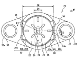
- the body 20 includes a body partition wall 22, a fitting peripheral wall 24, a fitting hole 26, a communication hole 28, a body engaging portion 30, and a flange portion 32.
- the body partition wall 22 is formed in a disc shape and partitions the storage chamber 12.
- a plurality of protruding body stoppers 23 are provided on the body partition wall 22 on the cover 40 side. Each body stopper 23 extends along the radial direction of the body partition wall 22.
- the body stoppers 23 are arranged at equal intervals (for example, 90 ° intervals) in the circumferential direction of the body partition wall 22.
- the fitting peripheral wall 24 is formed so as to surround the outer periphery of the disk-shaped body partition wall 22.
- the fitting peripheral wall 24 has a peripheral wall surface 24a on the outer periphery along a predetermined fitting direction WF.
- the fitting direction WF in the present embodiment is a disc-shaped thickness direction and is a direction from the cover 40 toward the body 20.
- the fitting hole 26 is provided on the cover 40 side at the center of the disc-shaped body partition wall 22 on the inner peripheral side of the fitting peripheral wall 24, and is cylindrical in the fitting direction WF with respect to the body partition wall 22. It is recessed.
- the communication hole 28 is provided through the fitting hole 26 and communicates with the oil pan 1 by being recessed in the fitting direction WF. That is, the body 20 is penetrated by the fitting hole 26 and the communication hole 28.
- a plurality of body engaging portions 30 are formed at intervals on the outer periphery of the body partition wall 22 so as to divide the fitting peripheral wall 24.
- four body engaging portions 30 are formed.
- Each body engaging portion 30 is provided with an engaging hole 30a penetrating in the fitting direction WF.
- a claw-like engagement projection 30b is provided inside each engagement hole 30a.
- the side surface of each engagement protrusion 30b is inclined with respect to the fitting direction WF, facing the fitting direction WF and facing the fitting surface 30c substantially perpendicular to the fitting direction WF, and facing the opposite direction to the fitting direction WF. It forms a slope 30d.
- the flange portion 32 is formed in a bowl shape on the outer peripheral side of the body partition wall 22 formed in a disc shape.
- An assembly ring 32a formed in a cylindrical shape with metal is embedded in the flange portion 32.
- the flange portion 32 of the body 20 can be assembled to the oil pan 1 by screwing the bracket 2 with the assembly ring 32a.
- the cover 40 is formed into a bottomed cylindrical shape as a whole by using, for example, PPS resin which is the same material as the body 20.
- the cover 40 integrally includes a bottom wall 42, an outer cylinder 44, and an inner shaft 46, and is fitted to the body 20 by the outer cylinder 44 and the inner shaft 46.
- the bottom wall 42 is disposed in a direction opposite to the mating direction WF in the cover 40 and is formed in a disc shape.
- the outer cylinder 44 protrudes from the outer peripheral part of the bottom wall 42 along the fitting direction WF, and is formed in a cylindrical shape.
- the outer cylinder 44 is fitted into the fitting peripheral wall 24 in a press-fit state along the fitting direction WF.
- the outer cylinder 44 has outer cylinder engaging portions 44 a provided at four locations corresponding to the body engaging portions 30 in the circumferential direction.
- Each outer cylinder engaging portion 44a is provided so as to be elastically deformable, and forms an engaging claw 44b.
- Each engagement claw 44b is further extended in the fitting direction WF from the tip of the outer cylinder 44 so that it can be inserted into each engagement hole 30a. In this way, each outer cylinder engaging portion 44a and each body engaging portion 30 are engaged.
- the inner shaft 46 protrudes along the fitting direction WF from the inner peripheral portion of the bottom wall 42 on the inner peripheral side of the outer cylinder 44 and is formed in a cylindrical shape.
- the inner shaft 46 is fitted in the fitting hole 26 along the fitting direction WF.
- cover stoppers 43 are provided on the bottom wall 42 on the body 20 side. Each cover stopper 43 extends radially from the inner shaft 46 toward the outer cylinder 44. The cover stoppers 43 are arranged at equal intervals (for example, 60 ° intervals) in the circumferential direction of the bottom wall 42.
- the float 50 has a foam 52 and a magnet 54, and can float on the liquid level of the engine oil.
- the foam 52 is formed in a cylindrical shape with a material having a specific gravity smaller than that of engine oil such as foamed phenol resin.
- An annular holding groove 52 a is formed on the inner peripheral side of the foam 52.
- the magnet 54 is a permanent magnet such as ferrite and is formed in a cylindrical shape. The magnet 54 is held in the foam 52 by being fitted in the holding groove 52 a of the foam 52.
- the float 50 having such a configuration is disposed between the outer cylinder 44 and the inner shaft 46 by being inserted through the inner shaft 46 of the cover 40, and follows the liquid level LL and is guided to the inner shaft 46. While being done, it reciprocates along the direction opposite to the fitting direction WF and the fitting direction WF.
- the float 50 is restricted from moving toward the body 20 by contact with the body stopper 23, and is restricted from moving toward the cover 40 by contact with the cover stopper 43.
- the reed switch 60 is a detection element that detects the position of the float 50 that moves along the fitting direction WF.
- the reed switch 60 has a glass tube 62 formed in a cylindrical shape, and a pair of leads 64a-b extending from both ends of the glass tube 62.
- the reed switch 60 is inserted into the inner shaft 46 in a posture in which the axial direction of the glass tube 62 is aligned with the fitting direction WF, and is disposed over the fitting hole 26 and the communication hole 28.
- the glass tube 62 is a hollow cylindrical glass tube, and each end portion (hereinafter referred to as a lead end portion) of each lead 64a-b is liquid-tightly accommodated.
- Each lead end portion is provided so as to be able to bend, and faces each other with a predetermined interval.
- each lead end attracts each other by being magnetized to different magnetic poles.
- the respective lead end portions come into contact with each other, and the reed switch 60 is turned on so as to be conductive between the respective leads 64a and 64b.
- the lead ends do not contact each other, and the reed switch 60 is turned off.
- Terminals 70a and 70b are formed in a strip shape from a conductive material such as brass.
- the terminals 70a and 70b are held in the body 20 by being insert-molded in the body 20.
- One terminal 70 a is accommodated in the inner shaft 46 and extends to a position closer to the bottom wall 42 than the glass tube 62.
- the terminal 70a is connected to one lead 64a and supports the lead 64a.
- the other terminal 70b is connected to the other lead 64b in the vicinity of the fitting hole 26, and supports the lead 64b.
- the reed switch 60 is held with respect to the body 20 by being attached to each terminal 70a-b.
- the float 50 When the liquid level detection device 100 is installed in the oil pan 1 in this way, the float 50 is fitted to the reed switch 60 inserted in the inner shaft 46 when the engine oil liquid level LL is sufficiently high. It is moving in the direction WF. In this case, since the magnet 54 is close to the reed switch 60, the reed switch 60 is turned on. On the other hand, when the engine oil decreases, the float 50 moves in the direction opposite to the fitting direction WF with respect to the reed switch 60 inserted in the inner shaft 46. In this case, since the magnet 54 is separated from the reed switch 60, the reed switch 60 is turned off. That is, the liquid level detecting device 100 can detect the level LL of the engine oil stored in the oil pan 1 by detecting the position of the float 50 where the reed switch 60 moves along the fitting direction WF. It becomes possible.
- the assembly process of the body 20 and the cover 40 will be described as a method of manufacturing the liquid level detection device 100 according to the first embodiment with reference to FIGS.
- the lead switch 60 is attached in advance to the terminals 70a and 70b by welding and heat caulking on the body 20 before the assembly process. Further, the float 50 is inserted into the inner shaft 46 in the cover 40 before the assembly process. However, in FIGS. 5 to 7, the reed switch 60, the terminals 70a and 70b, and the float 50 are omitted.
- the side of the body 20 on which the fitting peripheral wall 24 and the fitting hole 26 are formed is opposed to the side of the cover 40 on which the tip of the outer cylinder 44 and the tip of the inner shaft 46 are formed. Then, the cover 40 is assembled to the body 20 along the fitting direction WF.
- the tip of the inner shaft 46 of the cover 40 reaches the opening of the fitting hole 26 (the position of the cover 40 is set to the initial position). P0).
- the outer diameter DS at the tip of the inner shaft 46 is substantially the same as the diameter DH of the fitting hole 26, the inner shaft 46 is fitted into the fitting hole 26 along the fitting direction WF.
- the cover 40 is guided by the fitting so as to be assembled in a direction along the fitting direction WF.
- the engaging claws 44b of the outer cylinder engaging portion 44a are not in contact with the engaging protrusions 30b of the body engaging portion 30 and are in a free state.
- the outer cylinder engaging portion 44 a is connected to the body engaging portion 30. Contact. More specifically, the engaging claw 44b of the outer cylinder engaging portion 44a comes into contact with the engaging protrusion 30b of the body engaging portion 30 at the inclined surface 30d (the position of the cover 40 is set to the first position P1). ).
- the end of the outer cylinder 44 reaches the fitting peripheral wall 24 (not shown).
- the inner diameter DP at the tip of the outer cylinder 44 is formed smaller than the outer diameter DW of the fitting peripheral wall 24 by, for example, about 0.2 to 0.5 mm. Therefore, by pressing the cover 40 in the fitting direction WF, the outer cylinder 44 is deformed to the outer peripheral side and starts fitting to the fitting peripheral wall 24 in the press-fitted state.
- the outer cylinder engaging portion 44 a is pressed by the body engaging portion 30 with the fitting of the cover 40 to the body 20. Elastically deforms. More specifically, the engaging claw 44b of the outer cylinder engaging portion 44a is pressed along the inclined surface 30d of the engaging protrusion 30b of the body engaging portion 30 and is elastically deformed to the inner peripheral side (this cover).
- the position 40 is set as the second position P2.
- the outer cylinder engaging portion 44 a is elastically restored and the body engaging portion 30.
- Engage with More specifically, the engaging claw 44b of the outer cylinder engaging portion 44a gets over the engaging protrusion 30b of the body engaging portion 30 and wraps around the back of the engaging surface 30c, so that the engaging claw 44b and the engaging protrusion 30b (The position of the cover 40 is set as the third position P3).
- the tip of the inner shaft 46 stops at the boundary between the fitting hole 26 and the communication hole 28 at the third position P3.
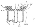
- the distance at which the outer cylinder 44 is fitted to the fitting peripheral wall 24 is defined as an outer cylinder fitting distance SP.
- the outer cylinder fitting distance SP corresponds to a distance along the fitting direction WF between the tip of the outer cylinder 44 and the end of the peripheral wall surface 24a, as shown in FIG.
- the distance at which the inner shaft 46 is fitted to the fitting hole 26 is defined as an inner shaft fitting distance SS.
- the inner shaft fitting distance SS corresponds to a distance along the fitting direction WF between the tip of the inner shaft 46 and the opening of the fitting hole 26 as shown in FIG.
- the distance between the first position P1 indicated by a two-dot chain line in FIG. 2 and the third position P3 indicated by a solid line in FIG. 2 is defined as an engagement distance SE.
- the engagement distances SE corresponding to the body engaging portions 30 and the outer cylinder engaging portions 44a are set to be substantially the same.
- At least one of the outer cylinder fitting distance SP and the inner shaft fitting distance SS is set to be larger than the engagement distance SE. More specifically, the inner shaft fitting distance SS is the largest, the engagement distance SE is the next largest, and the outer cylinder fitting distance SP is the smallest.
- the inner shaft 46 corresponding to the largest inner shaft fitting distance SS is first fitted into the fitting hole 26, and the outer cylinder corresponding to the outer cylinder fitting distance SP is started.
- the fitting of the cylinder 44 to the fitting peripheral wall 24 is started, and the contact between the outer cylinder engaging portion 44a and the body engaging portion 30 corresponding to the engaging distance SE is thereafter.
- the cover 40 is attached to the body 20 in a predetermined fitting direction.
- the outer tube 44 and the fitting peripheral wall 24 are fitted and the inner shaft 46 and the fitting hole 26 before the contact between the outer tube engaging portion 44a and the body engaging portion 30.
- At least one of the fittings is started.
- the outer cylinder engaging portion 44a contacts the body engaging portion 30 at the first position P1, and then the outer cylinder engaging portion 44a is moved to the body at the second position P2.
- the outer cylinder engaging part 44a is elastically restored and engaged with the body engaging part 30 at the third position P3 after being pressed and elastically deformed by the engaging part 30. According to this, after the cover 40 is guided so as to be assembled along the fitting direction WF, the outer cylinder engaging portion 44a is elastically deformed, so that the assembly can be performed smoothly. Further, since the body 20 and the cover 40 are fitted on the inner peripheral side and the outer peripheral side, respectively, the holding force of the cover 40 is increased and the vibration is restricted, so that the cover 40 can be prevented from falling off the body 20. As described above, it is possible to provide the liquid level detection device 100 that prevents the dropout.
- the body 20 has the communication hole 28 that can communicate with the oil pan 1 through the fitting hole 26.
- the inner shaft 46 is fitted into the fitting hole 26 that communicates with the communication hole 28, air can be released through the communication hole 28, so that the inner shaft 46 can be firmly fitted. As a result, dropout can be prevented.
- the second embodiment is a modification of the first embodiment.
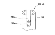
- the inner shaft 246 in the liquid level detection device 200 of the second embodiment projects along the fitting direction WF from the inner peripheral portion of the bottom wall 42 on the inner peripheral side of the outer cylinder 44, as in the first embodiment. It is formed in a cylindrical shape.
- the tip of the inner shaft 246 has a window 246a that allows deformation of the tip. More specifically, as shown in FIG. 8, two U-shaped notched windows 246 a are provided at the tip of the inner shaft 246 at positions facing each other.
- the inner shaft 246 is fitted into the fitting hole 26 along the fitting direction WF in a press-fitted state.
- the tip of the inner shaft 246 reaches the opening of the fitting hole 26 (the position of the cover 40 is initially set). Set as position P0).
- the outer diameter DS at the tip of the inner shaft 246 is formed to be larger than the diameter DH of the fitting hole 26 by, for example, about 0.2 to 0.5 mm. Therefore, by pressing the cover 40 in the fitting direction WF, the distal end of the inner shaft 246 that is allowed to be deformed by the window 246a is deformed to the inner peripheral side, and the fitting to the fitting peripheral wall 24 in the press-fitted state is performed. Start.
- the cover 40 is guided by this fitting so as to be assembled in a direction along the fitting direction WF.
- the engaging claw 44b of the outer cylinder engaging portion 44a is not in contact with the engaging protrusion 30b of the body engaging portion 30, and is in a free state.
- At least one of the outer cylinder fitting distance SP and the inner shaft fitting distance SS is set to be larger than the engagement distance SE. Therefore, it is possible to achieve the operational effects according to the first embodiment.
- the tip of the inner shaft 246 fitted into the fitting hole 26 in the press-fitted state has the window 246a that allows deformation of the tip. According to this, even if it is the front-end
- the third embodiment is a modification of the first embodiment.
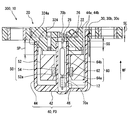
- the fitting peripheral wall 324 in the liquid level detection device 300 of the third embodiment protrudes in the direction opposite to the fitting direction WF with respect to the body partition wall 22.
- the fitting peripheral wall 324 has a peripheral wall surface 324a on the outer periphery along the fitting direction WF including the protruding range.
- the outer cylinder fitting distance SP and the inner shaft fitting distance SS are set to be larger than the engagement distance SE.
- the outer cylinder fitting distance SP is the largest
- the inner shaft fitting distance SS is the second largest
- the engagement distance SE is the smallest.
- the tip of the outer cylinder 44 reaches the fitting peripheral wall 324 (the position of the cover 40 is set to the initial position P0). And set).
- the inner diameter DP at the tip of the outer cylinder 44 is formed smaller than the outer diameter DW of the fitting peripheral wall 324 by, for example, about 0.2 to 0.5 mm. Therefore, by pressing the cover 40 in the fitting direction WF, the outer cylinder 44 is deformed to the outer peripheral side and starts fitting to the fitting peripheral wall 324 in the press-fitted state. And the cover 40 is guided by this fitting so that it may be assembled
- the engaging claws 44b of the outer cylinder engaging portion 44a are not in contact with the engaging protrusions 30b of the body engaging portion 30 and are in a free state.
- the tip of the inner shaft 46 of the cover 40 reaches the opening of the fitting hole 26, and the inner shaft 46 is fitted in the fitting hole 26 as in the first embodiment. Fitted.
- At least one of the outer cylinder fitting distance SP and the inner shaft fitting distance SS is set to be larger than the engagement distance SE. Therefore, it is possible to achieve the operational effects according to the first embodiment.
- the fitting peripheral wall 324 protrudes in the direction opposite to the fitting direction WF. According to this, since the outer cylinder fitting distance SP can be set as long as possible, it is easy to make the outer cylinder fitting distance SP larger than the engagement distance SE. As a result, dropout can be prevented.
- an element other than the reed switch 60 may be used.
- the Hall element may be used as a detection element after some processing for liquid resistance is performed.
- the magnitude of these distances may be other orders.
- the inner shaft fitting distance SS is the largest
- the outer cylinder fitting distance SP is the next largest
- the engagement distance SE may be set the smallest
- the outer cylinder fitting distance SP is the largest.
- the engagement distance SE may be set to be the largest
- the inner shaft fitting distance SS may be set to be the smallest.
- the body 20 may not have the communication hole 28 that can communicate with the oil pan 1.
- the outer diameter DS of the tip of the inner shaft 46 is formed larger than the diameter DH of the fitting hole 26, so that the inner shaft 46 is press-fit and the fitting hole 26 is
- the inner diameter DP at the tip of the outer cylinder 44 is substantially the same as the outer diameter DW of the fitting peripheral wall 24 so that the outer cylinder 44 is completely fitted to the fitting peripheral wall 24. May be.
- the fitting peripheral wall 24 may have a peripheral wall surface 24a on the inner periphery. Further, the outer cylinder 44 may be deformed to the inner peripheral side and fitted with the fitting peripheral wall 24 in a press-fitted state.
- the application target of the present disclosure is not limited to the detection of the engine oil liquid level LL.
- the present disclosure can be applied to a liquid level detection device in a container for other liquids mounted on the vehicle, such as brake fluid, engine coolant, and fuel.
- the present disclosure is applicable not only to vehicles but also to liquid level detection devices in containers provided in various consumer devices and various transport machines.
Abstract
According to the present invention, a first position (P1) where an outer cylinder engagement portion (44a) comes into contact with a body engagement portion (30) in conjunction with the fitting of a cover (40) to a body (20), a second position (P2) where the outer cylinder engagement portion (44a) is pressed by the body engagement portion (30) and undergoes elastic deformation, and a third position (P3) where the outer cylinder engagement portion (44a) undergoes elastic recovery and engages with the body engagement portion (30) are set. If the length of the portion where the outer cylinder (44) is fitted to a fitting peripheral wall (24, 324) is termed an outer cylinder fitting distance (SP), the length of the portion where an inner shaft (46, 246) is fitted to a fitting hole (26) defined as an inner shaft fitting distance (SS), and the distance between the first position (P1) and the third position (P3) termed an engagement distance (SE), then the outer cylinder fitting distance (SP) and/or the inner shaft fitting distance (SS) is larger than the engagement distance (SE).
Description
本出願は、2014年5月27日に出願された日本出願番号2014-109381号に基づくもので、ここにその記載内容を援用する。
This application is based on Japanese Patent Application No. 2014-109381 filed on May 27, 2014, the contents of which are incorporated herein by reference.
本開示は、容器に貯留された液体の液面レベルを検出する液面検出装置に関する。
The present disclosure relates to a liquid level detection device that detects a liquid level of a liquid stored in a container.
従来、容器に貯留された液体の液面レベルを検出する液面検出装置が知られている。例えば特許文献1に記載の液面検出装置では、ボデー(蓋体)と、液面に浮かぶフロートを覆う外筒、及びフロートの位置を検出する検出素子を収容するための内軸を一体的に形成するカバー(ハウジング)とを備えている。そして、カバーの上端に位置する開口部は、ボデーによって液密的に封止されている。
Conventionally, a liquid level detection device for detecting a liquid level of a liquid stored in a container is known. For example, in the liquid level detection device described in Patent Document 1, a body (lid), an outer cylinder that covers a float that floats on the liquid level, and an inner shaft that houses a detection element that detects the position of the float are integrated. And a cover (housing) to be formed. And the opening part located in the upper end of a cover is liquid-tightly sealed with the body.
ここで、特許文献1に記載の技術では、カバーの外筒及び内軸がボデーと嵌合することで、液密的な封止を実現するものと考えられる。しかしながら、この技術では、例えば車両等の容器内に設置され、液面検出装置に振動が作用すると、ボデーとカバーとの嵌合する箇所に摩耗が発生する恐れがあると考えられる。そして、当該摩耗によりがたつきが生じると、最悪、脱落に至る恐れがあった。
Here, in the technique described in Patent Document 1, it is considered that the outer cylinder and the inner shaft of the cover are fitted with the body to realize liquid-tight sealing. However, in this technique, for example, when it is installed in a container such as a vehicle and vibrations act on the liquid level detection device, it is considered that wear may occur at a place where the body and the cover are fitted. And, when rattling occurs due to the wear, there is a possibility that the worst case may occur.
そこで、本発明者は、弾性変形可能に設けられる外筒係合部をカバーに設けると共に、外筒係合部と係合可能に設けられるボデー係合部をボデーに設ける構成について検討した。しかしながら、この構成では、ボデーとカバーとの組付工程において、カバーが少し斜めに差し込まれると、外筒係合部に意図しない弾性変形が生じて、軸ぶれにより嵌合がスムーズに行なえない恐れや、外筒係合部が破損して歩留りが低下する恐れがあった。結果として、脱落を防止する液面検出装置を円滑に提供することが困難になっていた。
Therefore, the present inventor has examined a configuration in which an outer cylinder engaging portion provided in an elastically deformable manner is provided on the cover and a body engaging portion provided in an engageable manner with the outer cylinder engaging portion is provided in the body. However, in this configuration, in the assembly process of the body and the cover, if the cover is inserted slightly diagonally, unintended elastic deformation occurs in the outer cylinder engaging portion, and there is a risk that the shaft cannot be smoothly fitted. In addition, the outer cylinder engaging portion may be damaged and the yield may be reduced. As a result, it has been difficult to smoothly provide a liquid level detection device that prevents dropout.
本開示は、以上説明した問題に鑑みてなされたものであって、その目的は、脱落を防止する液面検出装置を提供することにある。
The present disclosure has been made in view of the problems described above, and an object thereof is to provide a liquid level detection device that prevents dropout.
上記目的を達成するため、本開示の1つの態様は、容器に貯留された液体の液面レベルを検出する液面検出装置において、容器に対して組付け可能であり、所定の嵌合方向に沿った周壁面を形成する嵌合周壁と、嵌合周壁の内周側において設けられる嵌合孔とを有するボデーと、ボデーに嵌合されるカバーであって、嵌合方向に沿って嵌合周壁に嵌合される外筒と、外筒の内周側において嵌合方向に沿って嵌合孔に嵌合される内軸とを一体的に形成するカバーと、外筒と内軸との間に配置され、液体に浮かぶフロートと、内軸に挿入され、フロートの位置を検出する検出素子と、を備え、外筒は、弾性変形可能に設けられる外筒係合部を有し、ボデーは、外筒係合部と係合可能に設けられるボデー係合部を有し、カバーのボデーへの嵌合に伴って外筒係合部がボデー係合部と接触する第1位置と、外筒係合部がボデー係合部により押圧されて弾性変形する第2位置と、外筒係合部が弾性復元してボデー係合部と係合する第3位置とが設定され、外筒が嵌合周壁と嵌合する箇所の距離を外筒嵌合距離と定義し、内軸が嵌合孔と嵌合する箇所の距離を内軸嵌合距離と定義し、第1位置と第3位置との距離を係合距離と定義すると、外筒嵌合距離及び内軸嵌合距離のうち少なくとも一方は、係合距離よりも大きいことを特徴とする。
In order to achieve the above object, according to one aspect of the present disclosure, in a liquid level detection device that detects a liquid level of a liquid stored in a container, the liquid level detection apparatus can be assembled to the container in a predetermined fitting direction. A body having a fitting peripheral wall that forms a peripheral wall surface along the inner periphery, a fitting hole provided on the inner peripheral side of the fitting peripheral wall, and a cover that is fitted to the body, and is fitted along the fitting direction. A cover integrally forming an outer cylinder fitted to the peripheral wall and an inner shaft fitted into the fitting hole along the fitting direction on the inner circumferential side of the outer cylinder; and the outer cylinder and the inner shaft And a float that floats on the liquid and a detection element that is inserted into the inner shaft and detects the position of the float, and the outer cylinder has an outer cylinder engaging portion that is provided so as to be elastically deformable. Has a body engaging part that can be engaged with the outer cylinder engaging part, and fits the cover to the body Thus, the first position where the outer cylinder engaging portion comes into contact with the body engaging portion, the second position where the outer cylinder engaging portion is pressed and elastically deformed by the body engaging portion, and the outer cylinder engaging portion is elastically restored. The third position for engaging with the body engaging portion is set, and the distance at which the outer cylinder is fitted with the fitting peripheral wall is defined as the outer cylinder fitting distance, and the inner shaft is fitted with the fitting hole. When the distance between the first position and the third position is defined as the engagement distance, at least one of the outer cylinder engagement distance and the inner shaft engagement distance is It is characterized by being larger than the combined distance.
これにより、係合距離よりも大きい外筒嵌合距離及び内軸嵌合距離のうち少なくとも一方の嵌合距離によれば、カバーをボデーに所定の嵌合方向に沿って嵌合する場合、外筒係合部とボデー係合部との接触よりも先に、外筒と嵌合周壁との嵌合及び内軸と嵌合孔との嵌合のうち少なくとも一方が開始されることとなる。そして、カバーのボデーへの嵌合に伴って、第1位置において外筒係合部がボデー係合部と接触した後、第2位置において外筒係合部がボデー係合部により押圧されて弾性変形し、その後第3位置において外筒係合部が弾性復元してボデー係合部と係合する。これによれば、カバーが嵌合方向に沿って組み付けられるように案内された後に、外筒係合部が弾性変形された状態となるので、円滑に組み付けを行なうことができる。また、内周側と外周側とで、それぞれボデーとカバーとを嵌合するので、カバーの保持力が高まると共に振動が規制され、カバーがボデーから脱落することを防止できる。以上により、脱落を防止する液面検出装置を提供することができる。
Thus, according to at least one of the outer cylinder fitting distance and the inner shaft fitting distance larger than the engagement distance, when the cover is fitted to the body along a predetermined fitting direction, Prior to the contact between the tube engaging portion and the body engaging portion, at least one of the fitting between the outer tube and the fitting peripheral wall and the fitting between the inner shaft and the fitting hole is started. Then, with the fitting of the cover to the body, after the outer cylinder engaging portion comes into contact with the body engaging portion at the first position, the outer cylinder engaging portion is pressed by the body engaging portion at the second position. The outer cylinder engaging portion is then elastically restored and engaged with the body engaging portion at the third position. According to this, after the cover is guided so as to be assembled along the fitting direction, the outer tube engaging portion is elastically deformed, so that the assembly can be performed smoothly. Further, since the body and the cover are fitted on the inner peripheral side and the outer peripheral side, respectively, the holding force of the cover is increased and the vibration is restricted, so that the cover can be prevented from falling off the body. As described above, it is possible to provide a liquid level detection device that prevents dropping.
本開示についての上記目的およびその他の目的、特徴や利点は、添付の図面を参照しながら下記の詳細な記述により、より明確になる。その図面は、
第1実施形態における液面検出装置がオイルパンに設置された状態を示す図である。
第1実施形態における本体部を示す断面図であって、組付工程における第3位置も示す図である。
第1実施形態におけるボデーの平面図である。
第1実施形態におけるカバーの底面図である。
第1実施形態における組付工程における第0位置を模式的に示す断面図である。
第1実施形態における組付工程における第1位置を模式的に示す断面図である。
第1実施形態における組付工程における第2位置を模式的に示す断面図である。
第2実施形態における内軸の先端を示す斜視図である。
第3実施形態における本体部を示す断面図であって、図2に対応する図である。
The above and other objects, features and advantages of the present disclosure will become more apparent from the following detailed description with reference to the accompanying drawings. The drawing
It is a figure which shows the state in which the liquid level detection apparatus in 1st Embodiment was installed in the oil pan. It is sectional drawing which shows the main-body part in 1st Embodiment, Comprising: It is a figure which also shows the 3rd position in an assembly | attachment process. It is a top view of the body in a 1st embodiment. It is a bottom view of the cover in a 1st embodiment. It is sectional drawing which shows typically the 0th position in the assembly | attachment process in 1st Embodiment. It is sectional drawing which shows typically the 1st position in the assembly | attachment process in 1st Embodiment. It is sectional drawing which shows typically the 2nd position in the assembly | attachment process in 1st Embodiment. It is a perspective view which shows the front-end | tip of the inner shaft in 2nd Embodiment. It is sectional drawing which shows the main-body part in 3rd Embodiment, Comprising: It is a figure corresponding to FIG.
以下、複数の実施形態を図面に基づいて説明する。なお、各実施形態において対応する構成要素には同一の符号を付すことにより、重複する説明を省略する場合がある。各実施形態において構成の一部分のみを説明している場合、当該構成の他の部分については、先行して説明した他の実施形態の構成を適用することができる。また、各実施形態の説明において明示している構成の組み合わせばかりではなく、特に組み合わせに支障が生じなければ、明示していなくても複数の実施形態の構成同士を部分的に組み合せることができる。
(第1実施形態)
図1に示すように、第1実施形態による液面検出装置100は、車両の内燃機関に搭載され、容器としてのオイルパン1内に設置されている。オイルパン1は、内燃機関のシリンダーブロックの底面に取り付けられ、液体としてのエンジンオイルを貯留している。液面検出装置100は、オイルパン1に貯留されたエンジンオイルの液面レベルLLを検出する。 Hereinafter, a plurality of embodiments will be described with reference to the drawings. In addition, the overlapping description may be abbreviate | omitted by attaching | subjecting the same code | symbol to the corresponding component in each embodiment. When only a part of the configuration is described in each embodiment, the configuration of the other embodiment described above can be applied to the other part of the configuration. In addition, not only combinations of configurations explicitly described in the description of each embodiment, but also the configurations of a plurality of embodiments can be partially combined even if they are not explicitly specified unless there is a problem with the combination. .
(First embodiment)
As shown in FIG. 1, the liquidlevel detection device 100 according to the first embodiment is mounted on an internal combustion engine of a vehicle and installed in an oil pan 1 as a container. The oil pan 1 is attached to the bottom surface of a cylinder block of an internal combustion engine, and stores engine oil as a liquid. The liquid level detection device 100 detects the liquid level LL of the engine oil stored in the oil pan 1.
(第1実施形態)
図1に示すように、第1実施形態による液面検出装置100は、車両の内燃機関に搭載され、容器としてのオイルパン1内に設置されている。オイルパン1は、内燃機関のシリンダーブロックの底面に取り付けられ、液体としてのエンジンオイルを貯留している。液面検出装置100は、オイルパン1に貯留されたエンジンオイルの液面レベルLLを検出する。 Hereinafter, a plurality of embodiments will be described with reference to the drawings. In addition, the overlapping description may be abbreviate | omitted by attaching | subjecting the same code | symbol to the corresponding component in each embodiment. When only a part of the configuration is described in each embodiment, the configuration of the other embodiment described above can be applied to the other part of the configuration. In addition, not only combinations of configurations explicitly described in the description of each embodiment, but also the configurations of a plurality of embodiments can be partially combined even if they are not explicitly specified unless there is a problem with the combination. .
(First embodiment)
As shown in FIG. 1, the liquid
液面検出装置100は、コネクタ部6、本体部10、及びワイヤ7を主として構成されている。コネクタ部6は、オイルパン1の側壁に設けられた開口1aを液密に塞ぐと共に、外部の車載機器(例えば、コンビネーションメータ等)と電気的に接続させるための相手側のコネクタ部(図示しない)と嵌合可能に形成されている。本体部10は、例えばブラケット2を介して、図1の設置状態においてオイルパン1に対して固定されている。そして、本体部10は、オイルパン1に貯留されたエンジンオイルの液面レベルLLを検出可能となっている。ワイヤ7は、コネクタ部6と本体部10とを電気的に接続しており、例えばブラケット2に這わせて配置されている。このようにして、液面検出装置100は、本体部10からの検出信号を、ワイヤ7及びコネクタ部6を介して、外部へ出力可能となっている。
The liquid level detection device 100 mainly includes a connector part 6, a main body part 10, and a wire 7. The connector portion 6 liquid-tightly closes the opening 1a provided on the side wall of the oil pan 1, and is a mating connector portion (not shown) for electrically connecting to an external vehicle-mounted device (for example, a combination meter). ) And can be fitted. The main body 10 is fixed to the oil pan 1 in the installed state of FIG. The main body 10 can detect the liquid level LL of the engine oil stored in the oil pan 1. The wire 7 electrically connects the connector portion 6 and the main body portion 10, and is disposed, for example, over the bracket 2. Thus, the liquid level detection device 100 can output the detection signal from the main body 10 to the outside via the wire 7 and the connector unit 6.
以下、図2~7に基づいて、液面検出装置100の本体部10について詳細に説明する。液面検出装置100の本体部10は、図2に示すように、ボデー20、カバー40、フロート50、及び検出素子としてのリードスイッチ60を備えている。
Hereinafter, the main body 10 of the liquid level detection device 100 will be described in detail with reference to FIGS. As shown in FIG. 2, the main body 10 of the liquid level detection device 100 includes a body 20, a cover 40, a float 50, and a reed switch 60 as a detection element.
図2,3に示すボデーは、例えばポリフェニレンサルファイド(PPS)樹脂により形成されている。ボデー20は、ボデー区画壁22、嵌合周壁24、嵌合孔26、連通孔28、ボデー係合部30、及びフランジ部32を有している。
The bodies shown in FIGS. 2 and 3 are made of, for example, polyphenylene sulfide (PPS) resin. The body 20 includes a body partition wall 22, a fitting peripheral wall 24, a fitting hole 26, a communication hole 28, a body engaging portion 30, and a flange portion 32.
ボデー区画壁22は、円盤状に形成され、収容室12を区画する。ボデー区画壁22においてカバー40側には、突起状のボデーストッパ23が複数設けられている。各ボデーストッパ23は、ボデー区画壁22の径方向に沿って延伸している。各ボデーストッパ23は、ボデー区画壁22の周方向に等間隔(例えば、90°間隔)で配置されている。
The body partition wall 22 is formed in a disc shape and partitions the storage chamber 12. A plurality of protruding body stoppers 23 are provided on the body partition wall 22 on the cover 40 side. Each body stopper 23 extends along the radial direction of the body partition wall 22. The body stoppers 23 are arranged at equal intervals (for example, 90 ° intervals) in the circumferential direction of the body partition wall 22.
嵌合周壁24は、円盤状のボデー区画壁22の外周を囲んで形成されている。嵌合周壁24は、所定の嵌合方向WFに沿った周壁面24aを外周に有している。本実施形態における嵌合方向WFとは、円盤状の厚み方向であって、カバー40からボデー20へと向かう方向となっている。
The fitting peripheral wall 24 is formed so as to surround the outer periphery of the disk-shaped body partition wall 22. The fitting peripheral wall 24 has a peripheral wall surface 24a on the outer periphery along a predetermined fitting direction WF. The fitting direction WF in the present embodiment is a disc-shaped thickness direction and is a direction from the cover 40 toward the body 20.
嵌合孔26は、嵌合周壁24の内周側において、円盤状のボデー区画壁22の中央にて、カバー40側に設けられ、ボデー区画壁22に対して嵌合方向WFに円柱状に凹んでいる。
The fitting hole 26 is provided on the cover 40 side at the center of the disc-shaped body partition wall 22 on the inner peripheral side of the fitting peripheral wall 24, and is cylindrical in the fitting direction WF with respect to the body partition wall 22. It is recessed.
連通孔28は、嵌合孔26を通じて設けられ、嵌合方向WFに凹むことでオイルパン1内に連通している。すなわち、嵌合孔26及び連通孔28によって、ボデー20は貫通されている。
The communication hole 28 is provided through the fitting hole 26 and communicates with the oil pan 1 by being recessed in the fitting direction WF. That is, the body 20 is penetrated by the fitting hole 26 and the communication hole 28.
ボデー係合部30は、ボデー区画壁22の外周において、嵌合周壁24を分断するように、互いに間隔を空けて複数形成されている。特に本実施形態では、ボデー係合部30は、4つ形成されている。各ボデー係合部30には、嵌合方向WFに貫通する係合孔30aが設けられている。各係合孔30aの内部には、爪状の係合突起30bが設けられている。各係合突起30bの側面は、嵌合方向WFを向いて嵌合方向WFと実質垂直な係合面30cと、嵌合方向WFとは反対方向を向いて嵌合方向WFに対して傾斜する斜面30dとをなしている。
A plurality of body engaging portions 30 are formed at intervals on the outer periphery of the body partition wall 22 so as to divide the fitting peripheral wall 24. In particular, in the present embodiment, four body engaging portions 30 are formed. Each body engaging portion 30 is provided with an engaging hole 30a penetrating in the fitting direction WF. A claw-like engagement projection 30b is provided inside each engagement hole 30a. The side surface of each engagement protrusion 30b is inclined with respect to the fitting direction WF, facing the fitting direction WF and facing the fitting surface 30c substantially perpendicular to the fitting direction WF, and facing the opposite direction to the fitting direction WF. It forms a slope 30d.
フランジ部32は、円盤状に形成されたボデー区画壁22の外周側に鍔状に形成されている。フランジ部32には、金属により円筒状に形成された組付リング32aが埋設されている。ボデー20のフランジ部32は、組付リング32aを使ってブラケット2にネジ止めを行なうことで、オイルパン1に対して組付け可能となっている。
The flange portion 32 is formed in a bowl shape on the outer peripheral side of the body partition wall 22 formed in a disc shape. An assembly ring 32a formed in a cylindrical shape with metal is embedded in the flange portion 32. The flange portion 32 of the body 20 can be assembled to the oil pan 1 by screwing the bracket 2 with the assembly ring 32a.
カバー40は、図2,4に示すように、例えばボデー20と同一の素材であるPPS樹脂により、全体として有底の円筒状に形成されている。カバー40は、底壁42、外筒44、及び内軸46を一体的に有しており、外筒44及び内軸46によってボデー20に嵌合されている。
As shown in FIGS. 2 and 4, the cover 40 is formed into a bottomed cylindrical shape as a whole by using, for example, PPS resin which is the same material as the body 20. The cover 40 integrally includes a bottom wall 42, an outer cylinder 44, and an inner shaft 46, and is fitted to the body 20 by the outer cylinder 44 and the inner shaft 46.
底壁42は、カバー40における最も嵌合方向WFとは反対方向に配置され、円盤状に形成されている。
The bottom wall 42 is disposed in a direction opposite to the mating direction WF in the cover 40 and is formed in a disc shape.
外筒44は、底壁42の外周部から嵌合方向WFに沿って突出し、円筒状に形成されている。そして、外筒44は、嵌合方向WFに沿って嵌合周壁24に圧入状態で嵌合されている。また、外筒44は、周方向のボデー係合部30に対応する4箇所に設けられている外筒係合部44aを有する。各外筒係合部44aは、弾性変形可能に設けられ、係合爪44bを形成している。各係合爪44bは、各係合孔30aに挿入可能なように、外筒44の先端から嵌合方向WFへさらに延伸している。このようにして、各外筒係合部44aと各ボデー係合部30とは、係合している。
The outer cylinder 44 protrudes from the outer peripheral part of the bottom wall 42 along the fitting direction WF, and is formed in a cylindrical shape. The outer cylinder 44 is fitted into the fitting peripheral wall 24 in a press-fit state along the fitting direction WF. Further, the outer cylinder 44 has outer cylinder engaging portions 44 a provided at four locations corresponding to the body engaging portions 30 in the circumferential direction. Each outer cylinder engaging portion 44a is provided so as to be elastically deformable, and forms an engaging claw 44b. Each engagement claw 44b is further extended in the fitting direction WF from the tip of the outer cylinder 44 so that it can be inserted into each engagement hole 30a. In this way, each outer cylinder engaging portion 44a and each body engaging portion 30 are engaged.
内軸46は、外筒44の内周側において、底壁42の内周部から嵌合方向WFに沿って突出し、円筒状に形成されている。そして、内軸46は、嵌合方向WFに沿って嵌合孔26に嵌合されている。
The inner shaft 46 protrudes along the fitting direction WF from the inner peripheral portion of the bottom wall 42 on the inner peripheral side of the outer cylinder 44 and is formed in a cylindrical shape. The inner shaft 46 is fitted in the fitting hole 26 along the fitting direction WF.
また、底壁42においてボデー20側には、カバーストッパ43が複数設けられている。各カバーストッパ43は、内軸46から外筒44へ向けて放射状に延設されている。各カバーストッパ43は、底壁42の周方向に、等間隔(例えば、60°間隔)で配置されている。
Further, a plurality of cover stoppers 43 are provided on the bottom wall 42 on the body 20 side. Each cover stopper 43 extends radially from the inner shaft 46 toward the outer cylinder 44. The cover stoppers 43 are arranged at equal intervals (for example, 60 ° intervals) in the circumferential direction of the bottom wall 42.
図2に示すように、フロート50は、発泡体52及びマグネット54を有しており、エンジンオイルの液面に浮かぶことが可能となっている。発泡体52は、例えば発泡させたフェノール樹脂等のエンジンオイルよりも比重の小さい材料によって円筒状に形成されている。発泡体52の内周側には、円環状の保持溝52aが形成されている。マグネット54は、フェライト等の永久磁石であり、円筒状に形成されている。そして、マグネット54は、発泡体52の保持溝52a内に内嵌されることにより、発泡体52に保持されている。このような構成のフロート50は、カバー40の内軸46に挿通されることにより、外筒44と内軸46との間に配置され、液面レベルLLに追従して、内軸46に案内されつつ、嵌合方向WF及び嵌合方向WFとは反対方向に沿って往復移動する。また、フロート50は、ボデーストッパ23との接触によりボデー20側への移動を規制されると共に、カバーストッパ43との接触によりカバー40側への移動を規制される。
As shown in FIG. 2, the float 50 has a foam 52 and a magnet 54, and can float on the liquid level of the engine oil. The foam 52 is formed in a cylindrical shape with a material having a specific gravity smaller than that of engine oil such as foamed phenol resin. An annular holding groove 52 a is formed on the inner peripheral side of the foam 52. The magnet 54 is a permanent magnet such as ferrite and is formed in a cylindrical shape. The magnet 54 is held in the foam 52 by being fitted in the holding groove 52 a of the foam 52. The float 50 having such a configuration is disposed between the outer cylinder 44 and the inner shaft 46 by being inserted through the inner shaft 46 of the cover 40, and follows the liquid level LL and is guided to the inner shaft 46. While being done, it reciprocates along the direction opposite to the fitting direction WF and the fitting direction WF. The float 50 is restricted from moving toward the body 20 by contact with the body stopper 23, and is restricted from moving toward the cover 40 by contact with the cover stopper 43.
リードスイッチ60は、嵌合方向WFに沿って移動するフロート50の位置を検出する検出素子である。リードスイッチ60は、円筒状に形成されたガラス管62、及びガラス管62の両端から延出する一対のリード64a~bを有している。リードスイッチ60は、ガラス管62の軸方向を嵌合方向WFに沿わせた姿勢にて、内軸46内に挿入され、嵌合孔26及び連通孔28の内部に亘って配置されている。具体的に、ガラス管62は、中空円筒状のガラス管であって、各リード64a~bの各端部(以下、リード端部)を液密に収容している。各リード端部は、撓み可能に設けられており、所定の間隔を開けて対向している。各リード端部にマグネット54からの磁界が作用すると、各リード端部は、異なる磁極に磁化することで、互いに引き合う。こうして各リード端部が互いに接触することとなり、リードスイッチ60は、各リード64a~b間にて導通可能なオン状態となる。反対に、各リード64a~bにマグネット54からの十分な磁界が作用しなければ、各リード端部は互いに接触せず、リードスイッチ60はオフ状態となる。
The reed switch 60 is a detection element that detects the position of the float 50 that moves along the fitting direction WF. The reed switch 60 has a glass tube 62 formed in a cylindrical shape, and a pair of leads 64a-b extending from both ends of the glass tube 62. The reed switch 60 is inserted into the inner shaft 46 in a posture in which the axial direction of the glass tube 62 is aligned with the fitting direction WF, and is disposed over the fitting hole 26 and the communication hole 28. Specifically, the glass tube 62 is a hollow cylindrical glass tube, and each end portion (hereinafter referred to as a lead end portion) of each lead 64a-b is liquid-tightly accommodated. Each lead end portion is provided so as to be able to bend, and faces each other with a predetermined interval. When a magnetic field from the magnet 54 acts on each lead end, each lead end attracts each other by being magnetized to different magnetic poles. Thus, the respective lead end portions come into contact with each other, and the reed switch 60 is turned on so as to be conductive between the respective leads 64a and 64b. On the other hand, if a sufficient magnetic field from the magnet 54 does not act on each lead 64a-b, the lead ends do not contact each other, and the reed switch 60 is turned off.
ターミナル70a~bは、黄銅等の導電性材料によって帯状に形成されている。ターミナル70a~bは、ボデー20にインサート成形されることで、このボデー20に保持されている。一方のターミナル70aは、内軸46に収容され、ガラス管62よりも底壁42に近接する位置まで延伸している。ターミナル70aは、一方のリード64aと接続されており、このリード64aを支持している。他方のターミナル70bは、嵌合孔26の近傍にて他方のリード64bと接続されており、このリード64bを支持している。各ターミナル70a~bに取り付けられることにより、リードスイッチ60は、ボデー20に対して保持される。
Terminals 70a and 70b are formed in a strip shape from a conductive material such as brass. The terminals 70a and 70b are held in the body 20 by being insert-molded in the body 20. One terminal 70 a is accommodated in the inner shaft 46 and extends to a position closer to the bottom wall 42 than the glass tube 62. The terminal 70a is connected to one lead 64a and supports the lead 64a. The other terminal 70b is connected to the other lead 64b in the vicinity of the fitting hole 26, and supports the lead 64b. The reed switch 60 is held with respect to the body 20 by being attached to each terminal 70a-b.
このようにして液面検出装置100がオイルパン1内に設置されると、エンジンオイルの液面レベルLLが十分高いとき、フロート50は内軸46に挿入されているリードスイッチ60に対し嵌合方向WFに移動している。この場合、マグネット54がリードスイッチ60に近接した状態となるため、リードスイッチ60は、オン状態となる。一方、エンジンオイルが減少した際には、フロート50は内軸46に挿入されているリードスイッチ60に対し嵌合方向WFとは反対方向に移動している。この場合、マグネット54がリードスイッチ60に離間した状態となるため、リードスイッチ60は、オフ状態となる。すなわち、リードスイッチ60が嵌合方向WFに沿って移動するフロート50の位置を検出することで、液面検出装置100がオイルパン1に貯留されたエンジンオイルの液面レベルLLを検出することが可能となる。
When the liquid level detection device 100 is installed in the oil pan 1 in this way, the float 50 is fitted to the reed switch 60 inserted in the inner shaft 46 when the engine oil liquid level LL is sufficiently high. It is moving in the direction WF. In this case, since the magnet 54 is close to the reed switch 60, the reed switch 60 is turned on. On the other hand, when the engine oil decreases, the float 50 moves in the direction opposite to the fitting direction WF with respect to the reed switch 60 inserted in the inner shaft 46. In this case, since the magnet 54 is separated from the reed switch 60, the reed switch 60 is turned off. That is, the liquid level detecting device 100 can detect the level LL of the engine oil stored in the oil pan 1 by detecting the position of the float 50 where the reed switch 60 moves along the fitting direction WF. It becomes possible.
ここで、図2,5~7を用いて、第1実施形態による液面検出装置100の製造方法として、ボデー20とカバー40との組付工程を説明する。
Here, the assembly process of the body 20 and the cover 40 will be described as a method of manufacturing the liquid level detection device 100 according to the first embodiment with reference to FIGS.
組付工程前のボデー20には、リードスイッチ60が溶接及び熱加締め等によってターミナル70a~bに事前に取り付けられている。また、組付工程前のカバー40には、フロート50が内軸46に挿通された状態となっている。ただし、図5~7においてはリードスイッチ60、ターミナル70a~b、及びフロート50を省略して図示する。
The lead switch 60 is attached in advance to the terminals 70a and 70b by welding and heat caulking on the body 20 before the assembly process. Further, the float 50 is inserted into the inner shaft 46 in the cover 40 before the assembly process. However, in FIGS. 5 to 7, the reed switch 60, the terminals 70a and 70b, and the float 50 are omitted.
組付工程において、ボデー20の嵌合周壁24及び嵌合孔26が形成された側と、カバー40の外筒44の先端及び内軸46の先端が形成された側とを対向させる。そして、カバー40を嵌合方向WFに沿ってボデー20に組み付ける。
In the assembly process, the side of the body 20 on which the fitting peripheral wall 24 and the fitting hole 26 are formed is opposed to the side of the cover 40 on which the tip of the outer cylinder 44 and the tip of the inner shaft 46 are formed. Then, the cover 40 is assembled to the body 20 along the fitting direction WF.
具体的に、第1実施形態では、まず最初に、図5に示すように、カバー40の内軸46の先端が嵌合孔26の開口に達する状態となる(このカバー40の位置を初期位置P0とする)。ここで、内軸46の先端の外径DSが嵌合孔26の径DHと実質同一となっていることにより、内軸46は、嵌合方向WFに沿って嵌合孔26に嵌合することが可能となっており、当該嵌合によってカバー40は嵌合方向WFに沿った方向に組み付けられるように案内される。初期位置P0の状態では、外筒係合部44aの係合爪44bは、ボデー係合部30の係合突起30bと接触しておらず、フリー状態となっている。
Specifically, in the first embodiment, first, as shown in FIG. 5, the tip of the inner shaft 46 of the cover 40 reaches the opening of the fitting hole 26 (the position of the cover 40 is set to the initial position). P0). Here, since the outer diameter DS at the tip of the inner shaft 46 is substantially the same as the diameter DH of the fitting hole 26, the inner shaft 46 is fitted into the fitting hole 26 along the fitting direction WF. The cover 40 is guided by the fitting so as to be assembled in a direction along the fitting direction WF. In the state of the initial position P0, the engaging claws 44b of the outer cylinder engaging portion 44a are not in contact with the engaging protrusions 30b of the body engaging portion 30 and are in a free state.
さらにカバー40を嵌合方向WFに沿って組み付けると、図6に示すように、このようなカバー40のボデー20への嵌合に伴って、外筒係合部44aがボデー係合部30と接触する。より詳細には、外筒係合部44aの係合爪44bがボデー係合部30の係合突起30bと斜面30dにおいて接触する状態となる(このカバー40の位置を第1位置P1と設定する)。
Further, when the cover 40 is assembled along the fitting direction WF, as shown in FIG. 6, as the cover 40 is fitted to the body 20, the outer cylinder engaging portion 44 a is connected to the body engaging portion 30. Contact. More specifically, the engaging claw 44b of the outer cylinder engaging portion 44a comes into contact with the engaging protrusion 30b of the body engaging portion 30 at the inclined surface 30d (the position of the cover 40 is set to the first position P1). ).
さらにカバー40を嵌合方向WFに沿って組み付けると、図示しないが、外筒44の先端が嵌合周壁24に達する状態となる。ここで、外筒44の先端の内径DPが嵌合周壁24の外径DWよりも、例えば0.2~0.5mm程度小さく形成されている。したがって、カバー40を嵌合方向WFに押圧することで、外筒44は外周側に変形されて、圧入状態での嵌合周壁24への嵌合を開始する。
Further, when the cover 40 is assembled along the fitting direction WF, the end of the outer cylinder 44 reaches the fitting peripheral wall 24 (not shown). Here, the inner diameter DP at the tip of the outer cylinder 44 is formed smaller than the outer diameter DW of the fitting peripheral wall 24 by, for example, about 0.2 to 0.5 mm. Therefore, by pressing the cover 40 in the fitting direction WF, the outer cylinder 44 is deformed to the outer peripheral side and starts fitting to the fitting peripheral wall 24 in the press-fitted state.
さらにカバー40を嵌合方向WFに沿って組み付けると、図7に示すように、カバー40のボデー20への嵌合に伴って、外筒係合部44aがボデー係合部30により押圧されて弾性変形する。より詳細には、外筒係合部44aの係合爪44bがボデー係合部30の係合突起30bの斜面30dに沿って押圧されて、内周側に弾性変形する状態となる(このカバー40の位置を第2位置P2と設定する)。
Further, when the cover 40 is assembled along the fitting direction WF, as shown in FIG. 7, the outer cylinder engaging portion 44 a is pressed by the body engaging portion 30 with the fitting of the cover 40 to the body 20. Elastically deforms. More specifically, the engaging claw 44b of the outer cylinder engaging portion 44a is pressed along the inclined surface 30d of the engaging protrusion 30b of the body engaging portion 30 and is elastically deformed to the inner peripheral side (this cover). The position 40 is set as the second position P2.)
さらにカバー40を嵌合方向WFに沿って組み付けると、図2に示すように、カバー40のボデー20への嵌合に伴って、外筒係合部44aが弾性復元してボデー係合部30と係合する。より詳細には、外筒係合部44aの係合爪44bがボデー係合部30の係合突起30bを乗り越え、係合面30cの裏に回り込んで、係合爪44bと係合突起30bとが係合される状態となる(このカバー40の位置を第3位置P3と設定する)。以上により、ボデー20とカバー40との組付工程が完了する。なお、第1実施形態では、第3位置P3において内軸46の先端が嵌合孔26と連通孔28との境界で止まる構造となっている。
Further, when the cover 40 is assembled along the fitting direction WF, as shown in FIG. 2, as the cover 40 is fitted to the body 20, the outer cylinder engaging portion 44 a is elastically restored and the body engaging portion 30. Engage with. More specifically, the engaging claw 44b of the outer cylinder engaging portion 44a gets over the engaging protrusion 30b of the body engaging portion 30 and wraps around the back of the engaging surface 30c, so that the engaging claw 44b and the engaging protrusion 30b (The position of the cover 40 is set as the third position P3). Thus, the assembly process of the body 20 and the cover 40 is completed. In the first embodiment, the tip of the inner shaft 46 stops at the boundary between the fitting hole 26 and the communication hole 28 at the third position P3.
組付工程後の液面検出装置100において、外筒44が嵌合周壁24と嵌合する箇所の距離を外筒嵌合距離SPと定義する。特に第1実施形態では、外筒嵌合距離SPは、図2に示すように、外筒44の先端と周壁面24aの端部との間の嵌合方向WFに沿った距離に該当する。また、内軸46が嵌合孔26と嵌合する箇所の距離を内軸嵌合距離SSと定義する。特に第1実施形態では、内軸嵌合距離SSは、図2に示すように、内軸46の先端と嵌合孔26の開口と間の嵌合方向WFに沿った距離に該当し、嵌合孔26の開口から嵌合孔26と連通孔28との境界までの距離と実質一致する。さらに、図2に二点鎖線で示す第1位置P1と図2に実線で示す第3位置P3との距離を係合距離SEと定義する。なお、本実施形態においては、各ボデー係合部30及び各外筒係合部44aに対応する各係合距離SEは、互いに実質同一に設定されている。
In the liquid level detection apparatus 100 after the assembly process, the distance at which the outer cylinder 44 is fitted to the fitting peripheral wall 24 is defined as an outer cylinder fitting distance SP. In particular, in the first embodiment, the outer cylinder fitting distance SP corresponds to a distance along the fitting direction WF between the tip of the outer cylinder 44 and the end of the peripheral wall surface 24a, as shown in FIG. Further, the distance at which the inner shaft 46 is fitted to the fitting hole 26 is defined as an inner shaft fitting distance SS. Particularly in the first embodiment, the inner shaft fitting distance SS corresponds to a distance along the fitting direction WF between the tip of the inner shaft 46 and the opening of the fitting hole 26 as shown in FIG. This substantially coincides with the distance from the opening of the joint hole 26 to the boundary between the fitting hole 26 and the communication hole 28. Furthermore, the distance between the first position P1 indicated by a two-dot chain line in FIG. 2 and the third position P3 indicated by a solid line in FIG. 2 is defined as an engagement distance SE. In the present embodiment, the engagement distances SE corresponding to the body engaging portions 30 and the outer cylinder engaging portions 44a are set to be substantially the same.
このような外筒嵌合距離SP及び内軸嵌合距離SSのうち少なくとも一方は、係合距離SEよりも大きく設定されている。より詳細には、内軸嵌合距離SSが最も大きく、その次に係合距離SEが大きく、外筒嵌合距離SPが最も小さくなっている。このような設定により、組付工程において、最も大きな内軸嵌合距離SSに対応する内軸46の嵌合孔26への嵌合が先に開始され、外筒嵌合距離SPに対応する外筒44の嵌合周壁24への嵌合が次に開始され、係合距離SEに対応する外筒係合部44aとボデー係合部30との接触がその後となる。
At least one of the outer cylinder fitting distance SP and the inner shaft fitting distance SS is set to be larger than the engagement distance SE. More specifically, the inner shaft fitting distance SS is the largest, the engagement distance SE is the next largest, and the outer cylinder fitting distance SP is the smallest. By such setting, in the assembly process, the inner shaft 46 corresponding to the largest inner shaft fitting distance SS is first fitted into the fitting hole 26, and the outer cylinder corresponding to the outer cylinder fitting distance SP is started. Next, the fitting of the cylinder 44 to the fitting peripheral wall 24 is started, and the contact between the outer cylinder engaging portion 44a and the body engaging portion 30 corresponding to the engaging distance SE is thereafter.
以上説明した第1実施形態の作用効果を以下に説明する。
The operational effects of the first embodiment described above will be described below.
第1実施形態によると、係合距離SEよりも大きい外筒嵌合距離SP及び内軸嵌合距離SSのうち少なくとも一方の嵌合距離によれば、カバー40をボデー20に所定の嵌合方向WFに沿って嵌合する場合、外筒係合部44aとボデー係合部30との接触よりも先に、外筒44と嵌合周壁24との嵌合及び内軸46と嵌合孔26との嵌合のうち少なくとも一方が開始されることとなる。そして、カバー40のボデー20への嵌合に伴って、第1位置P1において外筒係合部44aがボデー係合部30と接触した後、第2位置P2において外筒係合部44aがボデー係合部30により押圧されて弾性変形し、その後第3位置P3において外筒係合部44aが弾性復元してボデー係合部30と係合する。これによれば、カバー40が嵌合方向WFに沿って組み付けられるように案内された後に、外筒係合部44aが弾性変形された状態となるので、円滑に組み付けを行なうことができる。また、内周側と外周側とで、それぞれボデー20とカバー40とを嵌合するので、カバー40の保持力が高まると共に振動が規制され、カバー40がボデー20から脱落することを防止できる。以上により、脱落を防止する液面検出装置100を提供することができる。
According to the first embodiment, according to at least one of the outer cylinder fitting distance SP and the inner shaft fitting distance SS larger than the engagement distance SE, the cover 40 is attached to the body 20 in a predetermined fitting direction. In the case of fitting along the WF, the outer tube 44 and the fitting peripheral wall 24 are fitted and the inner shaft 46 and the fitting hole 26 before the contact between the outer tube engaging portion 44a and the body engaging portion 30. At least one of the fittings is started. As the cover 40 is fitted to the body 20, the outer cylinder engaging portion 44a contacts the body engaging portion 30 at the first position P1, and then the outer cylinder engaging portion 44a is moved to the body at the second position P2. The outer cylinder engaging part 44a is elastically restored and engaged with the body engaging part 30 at the third position P3 after being pressed and elastically deformed by the engaging part 30. According to this, after the cover 40 is guided so as to be assembled along the fitting direction WF, the outer cylinder engaging portion 44a is elastically deformed, so that the assembly can be performed smoothly. Further, since the body 20 and the cover 40 are fitted on the inner peripheral side and the outer peripheral side, respectively, the holding force of the cover 40 is increased and the vibration is restricted, so that the cover 40 can be prevented from falling off the body 20. As described above, it is possible to provide the liquid level detection device 100 that prevents the dropout.
また、第1実施形態によると、ボデー20は、嵌合孔26を通じてオイルパン1内に連通可能な連通孔28を有する。内軸46が連通孔28に通じる嵌合孔26に嵌合されると、連通孔28を通して空気を逃がすことができるので、しっかりと嵌合させることが可能となる。その結果、脱落を防止することができる。
(第2実施形態)
図8に示すように、第2実施形態は第1実施形態の変形例である。 Further, according to the first embodiment, thebody 20 has the communication hole 28 that can communicate with the oil pan 1 through the fitting hole 26. When the inner shaft 46 is fitted into the fitting hole 26 that communicates with the communication hole 28, air can be released through the communication hole 28, so that the inner shaft 46 can be firmly fitted. As a result, dropout can be prevented.
(Second Embodiment)
As shown in FIG. 8, the second embodiment is a modification of the first embodiment.
(第2実施形態)
図8に示すように、第2実施形態は第1実施形態の変形例である。 Further, according to the first embodiment, the
(Second Embodiment)
As shown in FIG. 8, the second embodiment is a modification of the first embodiment.
第2実施形態の液面検出装置200における内軸246は、第1実施形態と同様に、外筒44の内周側において、底壁42の内周部から嵌合方向WFに沿って突出し、円筒状に形成されている。ここで、内軸246の先端は、当該先端の変形を許容する窓246aを有している。より詳細には、図8に示すように、内軸246の先端には、U字型の切り欠き状の窓246aが互いに対向する箇所に2つ設けられている。そして、内軸246は、圧入状態で、嵌合方向WFに沿って嵌合孔26に嵌合されている。
The inner shaft 246 in the liquid level detection device 200 of the second embodiment projects along the fitting direction WF from the inner peripheral portion of the bottom wall 42 on the inner peripheral side of the outer cylinder 44, as in the first embodiment. It is formed in a cylindrical shape. Here, the tip of the inner shaft 246 has a window 246a that allows deformation of the tip. More specifically, as shown in FIG. 8, two U-shaped notched windows 246 a are provided at the tip of the inner shaft 246 at positions facing each other. The inner shaft 246 is fitted into the fitting hole 26 along the fitting direction WF in a press-fitted state.
このような液面検出装置200のボデー20とカバー40との組付工程において、まず最初に、内軸246の先端が嵌合孔26の開口に達する状態となる(このカバー40の位置を初期位置P0と設定する)。ここで、内軸246の先端の外径DSが嵌合孔26の径DHよりも例えば0.2~0.5mm程度大きく形成されている。したがって、カバー40を嵌合方向WFに押圧することで、窓246aにより変形が許容された内軸246の先端は内周側に変形されて、圧入状態での嵌合周壁24への嵌合を開始する。そして、第1実施形態と同様に、この嵌合によってカバー40は嵌合方向WFに沿った方向に組み付けられるように案内される。初期位置の状態では、外筒係合部44aの係合爪44bは、ボデー係合部30の係合突起30bと接触しておらず、フリー状態となっている。
In the assembly process of the body 20 and the cover 40 of the liquid level detection device 200, first, the tip of the inner shaft 246 reaches the opening of the fitting hole 26 (the position of the cover 40 is initially set). Set as position P0). Here, the outer diameter DS at the tip of the inner shaft 246 is formed to be larger than the diameter DH of the fitting hole 26 by, for example, about 0.2 to 0.5 mm. Therefore, by pressing the cover 40 in the fitting direction WF, the distal end of the inner shaft 246 that is allowed to be deformed by the window 246a is deformed to the inner peripheral side, and the fitting to the fitting peripheral wall 24 in the press-fitted state is performed. Start. As in the first embodiment, the cover 40 is guided by this fitting so as to be assembled in a direction along the fitting direction WF. In the state of the initial position, the engaging claw 44b of the outer cylinder engaging portion 44a is not in contact with the engaging protrusion 30b of the body engaging portion 30, and is in a free state.
以上説明した第2実施形態においても、外筒嵌合距離SP及び内軸嵌合距離SSのうち少なくとも一方は、係合距離SEよりも大きく設定されている。したがって、第1実施形態に準じた作用効果を奏することが可能となる。
Also in the second embodiment described above, at least one of the outer cylinder fitting distance SP and the inner shaft fitting distance SS is set to be larger than the engagement distance SE. Therefore, it is possible to achieve the operational effects according to the first embodiment.
また、第2実施形態によると、圧入状態で嵌合孔26に嵌合される内軸246の先端は、当該先端の変形を許容する窓246aを有している。これによれば、外筒44よりも外径DSが小さいことにより変形し難い内軸246の先端であっても、変形し易くなるので、容易に圧入状態で嵌合できる。その結果、脱落を防止することができる。
(第3実施形態)
図9に示すように、第3実施形態は第1実施形態の変形例である。 According to the second embodiment, the tip of theinner shaft 246 fitted into the fitting hole 26 in the press-fitted state has the window 246a that allows deformation of the tip. According to this, even if it is the front-end | tip of the inner shaft 246 which is hard to deform | transform because the outer diameter DS is smaller than the outer cylinder 44, since it becomes easy to deform | transform, it can fit in a press-fit state easily. As a result, dropout can be prevented.
(Third embodiment)
As shown in FIG. 9, the third embodiment is a modification of the first embodiment.
(第3実施形態)
図9に示すように、第3実施形態は第1実施形態の変形例である。 According to the second embodiment, the tip of the
(Third embodiment)
As shown in FIG. 9, the third embodiment is a modification of the first embodiment.
第3実施形態の液面検出装置300における嵌合周壁324は、図9に示すように、ボデー区画壁22に対して、嵌合方向WFとは反対方向に突出している。嵌合周壁324は、突出範囲を含めて嵌合方向WFに沿った周壁面324aを外周に有している。
As shown in FIG. 9, the fitting peripheral wall 324 in the liquid level detection device 300 of the third embodiment protrudes in the direction opposite to the fitting direction WF with respect to the body partition wall 22. The fitting peripheral wall 324 has a peripheral wall surface 324a on the outer periphery along the fitting direction WF including the protruding range.
そして、外筒嵌合距離SP及び内軸嵌合距離SSは、係合距離SEよりも大きく設定されている。ただし第3実施形態では、嵌合周壁324の突出により、外筒嵌合距離SPが最も大きく、その次に内軸嵌合距離SSが大きく、係合距離SEが最も小さくなっている。
The outer cylinder fitting distance SP and the inner shaft fitting distance SS are set to be larger than the engagement distance SE. However, in the third embodiment, due to the protrusion of the fitting peripheral wall 324, the outer cylinder fitting distance SP is the largest, the inner shaft fitting distance SS is the second largest, and the engagement distance SE is the smallest.
このような液面検出装置300のボデー20とカバー40との組付工程では、まず最初に、外筒44の先端が嵌合周壁324に達する状態となる(このカバー40の位置を初期位置P0と設定する)。ここで、外筒44の先端の内径DPが嵌合周壁324の外径DWよりも、例えば0.2~0.5mm程度小さく形成されている。したがって、カバー40を嵌合方向WFに押圧することで、外筒44は外周側に変形されて、圧入状態での嵌合周壁324への嵌合を開始する。そして、この嵌合によってカバー40は嵌合方向WFに沿った方向に組み付けられるように案内される。初期位置P0の状態では、外筒係合部44aの係合爪44bは、ボデー係合部30の係合突起30bと接触しておらず、フリー状態となっている。
In the assembly process of the body 20 and the cover 40 of the liquid level detection device 300, first, the tip of the outer cylinder 44 reaches the fitting peripheral wall 324 (the position of the cover 40 is set to the initial position P0). And set). Here, the inner diameter DP at the tip of the outer cylinder 44 is formed smaller than the outer diameter DW of the fitting peripheral wall 324 by, for example, about 0.2 to 0.5 mm. Therefore, by pressing the cover 40 in the fitting direction WF, the outer cylinder 44 is deformed to the outer peripheral side and starts fitting to the fitting peripheral wall 324 in the press-fitted state. And the cover 40 is guided by this fitting so that it may be assembled | attached in the direction along the fitting direction WF. In the state of the initial position P0, the engaging claws 44b of the outer cylinder engaging portion 44a are not in contact with the engaging protrusions 30b of the body engaging portion 30 and are in a free state.
さらにカバー40を嵌合方向WFに沿って組み付けると、カバー40の内軸46の先端が嵌合孔26の開口に達する状態となり、内軸46は、第1実施形態と同様に嵌合孔26に嵌合される。
Further, when the cover 40 is assembled along the fitting direction WF, the tip of the inner shaft 46 of the cover 40 reaches the opening of the fitting hole 26, and the inner shaft 46 is fitted in the fitting hole 26 as in the first embodiment. Fitted.
以上説明した第3実施形態においても、外筒嵌合距離SP及び内軸嵌合距離SSのうち少なくとも一方は、係合距離SEよりも大きく設定されている。したがって、第1実施形態に準じた作用効果を奏することが可能となる。
Also in the third embodiment described above, at least one of the outer cylinder fitting distance SP and the inner shaft fitting distance SS is set to be larger than the engagement distance SE. Therefore, it is possible to achieve the operational effects according to the first embodiment.
また、第3実施形態によると、嵌合周壁324は、嵌合方向WFとは反対方向に突出している。これによれば、外筒嵌合距離SPを可及的に長く設定することができるので、当該外筒嵌合距離SPを、係合距離SEよりも大きくすることが容易となる。その結果、脱落を防止することができる。
Further, according to the third embodiment, the fitting peripheral wall 324 protrudes in the direction opposite to the fitting direction WF. According to this, since the outer cylinder fitting distance SP can be set as long as possible, it is easy to make the outer cylinder fitting distance SP larger than the engagement distance SE. As a result, dropout can be prevented.
以上、複数の実施形態について説明したが、本開示は、それらの実施形態に限定して解釈されるものではなく、本開示の要旨を逸脱しない範囲内において種々の実施形態及び組み合わせに適用することができる。
Although a plurality of embodiments have been described above, the present disclosure is not construed as being limited to those embodiments, and can be applied to various embodiments and combinations without departing from the scope of the present disclosure. Can do.
具体的に、第1~第3実施形態に関する変形例1としては、検出素子は、フロート50の位置を検出するものであれば、リードスイッチ60以外の他の素子を用いてもよい。この例として、ホール素子に耐液性についての何らかの加工を施した上で、検出素子として用いてもよい。
Specifically, as a first modification regarding the first to third embodiments, as long as the detection element detects the position of the float 50, an element other than the reed switch 60 may be used. As an example of this, the Hall element may be used as a detection element after some processing for liquid resistance is performed.
第1~第3実施形態に関する変形例2としては、外筒嵌合距離SP及び内軸嵌合距離SSのうち一方が、係合距離SEよりも大きいという関係を満たす限り、これら距離の大きさの順序は他の順序であってもよい。この例として、内軸嵌合距離SSが最も大きく、その次に外筒嵌合距離SPが大きく、係合距離SEが最も小さく設定されていてもよく、又は外筒嵌合距離SPが最も大きく、その次に係合距離SEが大きく、内軸嵌合距離SSが最も小さく設定されていてもよい。
As a second modification related to the first to third embodiments, as long as one of the outer cylinder fitting distance SP and the inner shaft fitting distance SS satisfies the relationship that it is larger than the engagement distance SE, the magnitude of these distances The order of may be other orders. As this example, the inner shaft fitting distance SS is the largest, the outer cylinder fitting distance SP is the next largest, the engagement distance SE may be set the smallest, or the outer cylinder fitting distance SP is the largest. Then, the engagement distance SE may be set to be the largest, and the inner shaft fitting distance SS may be set to be the smallest.
第1~第3実施形態に関する変形例3としては、ボデー20は、オイルパン1内に連通可能な連通孔28を有していなくてもよい。
As a third modification related to the first to third embodiments, the body 20 may not have the communication hole 28 that can communicate with the oil pan 1.
第1~第3実施形態に関する変形例4としては、内軸46の先端の外径DSが嵌合孔26の径DHよりも大きく形成されることで内軸46が圧入状態で嵌合孔26に嵌合され、かつ、外筒44の先端の内径DPが嵌合周壁24の外径DWと実質同一となっていることで外筒44がすっぽりと嵌合周壁24に嵌合されるようにしてもよい。
As a fourth modification related to the first to third embodiments, the outer diameter DS of the tip of the inner shaft 46 is formed larger than the diameter DH of the fitting hole 26, so that the inner shaft 46 is press-fit and the fitting hole 26 is And the inner diameter DP at the tip of the outer cylinder 44 is substantially the same as the outer diameter DW of the fitting peripheral wall 24 so that the outer cylinder 44 is completely fitted to the fitting peripheral wall 24. May be.
第1~第3実施形態に関する変形例5としては、嵌合周壁24は周壁面24aを内周に形成してもよい。さらに、外筒44は内周側に変形されて、圧入状態で嵌合周壁24と嵌合してもよい。
As a fifth modified example related to the first to third embodiments, the fitting peripheral wall 24 may have a peripheral wall surface 24a on the inner periphery. Further, the outer cylinder 44 may be deformed to the inner peripheral side and fitted with the fitting peripheral wall 24 in a press-fitted state.
第1~第3実施形態に関する変形例6としては、本開示の適用対象は、エンジンオイルの液面レベルLLの検出に限られない。車両に搭載される他の液体、例えばブレーキフルード、エンジン冷却水、燃料等の容器内の液面検出装置に本開示は適用可能である。さらに、車両用に限らず、各種民生用機器、各種輸送機械が備える容器内の液面検出装置に、本開示は適用可能である。
As a sixth modified example related to the first to third embodiments, the application target of the present disclosure is not limited to the detection of the engine oil liquid level LL. The present disclosure can be applied to a liquid level detection device in a container for other liquids mounted on the vehicle, such as brake fluid, engine coolant, and fuel. Furthermore, the present disclosure is applicable not only to vehicles but also to liquid level detection devices in containers provided in various consumer devices and various transport machines.
本開示は、実施例に準拠して記述されたが、本開示は当該実施例や構造に限定されるものではないと理解される。本開示は、様々な変形例や均等範囲内の変形をも包含する。加えて、様々な組み合わせや形態、さらには、それらに一要素のみ、それ以上、あるいはそれ以下、を含む他の組み合わせや形態をも、本開示の範疇や思想範囲に入るものである。
Although the present disclosure has been described based on the embodiments, it is understood that the present disclosure is not limited to the embodiments and structures. The present disclosure includes various modifications and modifications within the equivalent range. In addition, various combinations and forms, as well as other combinations and forms including only one element, more or less, are within the scope and spirit of the present disclosure.
Claims (4)
- 容器(1)に貯留された液体の液面レベル(LL)を検出する液面検出装置において、
前記容器(1)に対して組み付け可能であり、所定の嵌合方向(WF)に沿った周壁面(24a,324a)を形成する嵌合周壁(24,324)と、前記嵌合周壁(24,324)の内周側において設けられる嵌合孔(26)とを有するボデー(20)と、
前記ボデー(20)に嵌合されるカバー(40)であって、前記嵌合方向(WF)に沿って前記嵌合周壁(24,324)に嵌合される外筒(44)と、前記外筒(44)の内周側において前記嵌合方向(WF)に沿って前記嵌合孔(26)に嵌合される内軸(46,246)とを一体的に形成するカバー(40)と、
前記外筒(44)と前記内軸(46,246)との間に配置され、前記液体に浮かぶフロート(50)と、
前記内軸(46,246)に挿入され、前記フロート(50)の位置を検出する検出素子(60)と、を備え、
前記外筒(44)は、弾性変形可能に設けられる外筒係合部(44a)を有し、
前記ボデー(20)は、前記外筒係合部(44a)と係合可能に設けられるボデー係合部(30)を有し、
前記カバー(40)の前記ボデー(20)への嵌合に伴って前記外筒係合部(44a)が前記ボデー係合部(30)と接触する第1位置(P1)と、前記外筒係合部(44a)が前記ボデー係合部(30)により押圧されて弾性変形する第2位置(P2)と、前記外筒係合部(44a)が弾性復元して前記ボデー係合部(30)と係合する第3位置(P3)とが設定され、
前記外筒(44)が前記嵌合周壁(24,324)と嵌合する箇所の距離を外筒嵌合距離(SP)と定義し、前記内軸(46,246)が前記嵌合孔(26)と嵌合する箇所の距離を内軸嵌合距離(SS)と定義し、前記第1位置(P1)と前記第3位置(P3)との距離を係合距離(SE)と定義すると、
前記外筒嵌合距離(SP)及び前記内軸嵌合距離(SS)のうち少なくとも一方は、前記係合距離(SE)よりも大きいことを特徴とする液面検出装置。 In the liquid level detection device for detecting the liquid level (LL) of the liquid stored in the container (1),
A fitting peripheral wall (24, 324) that can be assembled to the container (1) and forms a peripheral wall surface (24a, 324a) along a predetermined fitting direction (WF), and the fitting peripheral wall (24 , 324) and a body (20) having a fitting hole (26) provided on the inner peripheral side,
A cover (40) fitted to the body (20), the outer cylinder (44) fitted to the fitting peripheral wall (24, 324) along the fitting direction (WF); A cover (40) integrally forming an inner shaft (46, 246) fitted in the fitting hole (26) along the fitting direction (WF) on the inner peripheral side of the outer cylinder (44). When,
A float (50) disposed between the outer cylinder (44) and the inner shaft (46, 246) and floating in the liquid;
A detection element (60) that is inserted into the inner shaft (46, 246) and detects the position of the float (50),
The outer cylinder (44) has an outer cylinder engaging part (44a) provided so as to be elastically deformable,
The body (20) has a body engaging portion (30) provided to be engageable with the outer cylinder engaging portion (44a),
A first position (P1) where the outer cylinder engaging portion (44a) contacts the body engaging portion (30) as the cover (40) is fitted to the body (20), and the outer cylinder A second position (P2) where the engaging portion (44a) is pressed and elastically deformed by being pressed by the body engaging portion (30), and the outer cylinder engaging portion (44a) is elastically restored and the body engaging portion ( 30) and the third position (P3) to be engaged are set,
The distance between the outer cylinder (44) and the fitting peripheral wall (24, 324) is defined as the outer cylinder fitting distance (SP), and the inner shaft (46, 246) is the fitting hole ( 26) is defined as an inner shaft fitting distance (SS), and a distance between the first position (P1) and the third position (P3) is defined as an engagement distance (SE). ,
At least one of the outer cylinder fitting distance (SP) and the inner shaft fitting distance (SS) is larger than the engagement distance (SE). - 前記ボデー(20)は、前記嵌合孔(26)を通じて前記容器(1)内に連通可能な連通孔(28)を有することを特徴とする請求項1に記載の液面検出装置。 The liquid level detection device according to claim 1, wherein the body (20) has a communication hole (28) capable of communicating with the container (1) through the fitting hole (26).
- 圧入状態で前記嵌合孔(26)に嵌合される前記内軸(246)の先端は、前記先端の変形を許容する窓(246a)を有していることを特徴とする請求項1又は2に記載の液面検出装置。 The tip of the inner shaft (246) fitted into the fitting hole (26) in the press-fitted state has a window (246a) that allows deformation of the tip. 2. The liquid level detection apparatus according to 2.
- 前記嵌合周壁(324)は、前記嵌合方向(WF)とは反対方向に突出し、
前記外筒嵌合距離(SP)は、前記係合距離(SE)よりも大きいことを特徴とする請求項1から3のいずれか1項に記載の液面検出装置。 The fitting peripheral wall (324) protrudes in a direction opposite to the fitting direction (WF),
4. The liquid level detection device according to claim 1, wherein the outer cylinder fitting distance (SP) is larger than the engagement distance (SE). 5.
Applications Claiming Priority (2)
| Application Number | Priority Date | Filing Date | Title |
|---|---|---|---|
| JP2014109381A JP2015224937A (en) | 2014-05-27 | 2014-05-27 | Liquid level detector |
| JP2014-109381 | 2014-05-27 |
Publications (1)
| Publication Number | Publication Date |
|---|---|
| WO2015182109A1 true WO2015182109A1 (en) | 2015-12-03 |
Family
ID=54698459
Family Applications (1)
| Application Number | Title | Priority Date | Filing Date |
|---|---|---|---|
| PCT/JP2015/002631 WO2015182109A1 (en) | 2014-05-27 | 2015-05-25 | Liquid level detection device |
Country Status (2)
| Country | Link |
|---|---|
| JP (1) | JP2015224937A (en) |
| WO (1) | WO2015182109A1 (en) |
Citations (7)
| Publication number | Priority date | Publication date | Assignee | Title |
|---|---|---|---|---|
| JPS63214621A (en) * | 1987-03-02 | 1988-09-07 | Nissan Motor Co Ltd | Liquid level measuring instrument for fuel tank |
| JPH0293725U (en) * | 1989-01-13 | 1990-07-25 | ||
| JPH02103235U (en) * | 1989-02-03 | 1990-08-16 | ||
| JPH11316151A (en) * | 1998-04-30 | 1999-11-16 | Kansei Corp | Lead switch type position sensor |
| JP2000011828A (en) * | 1998-06-25 | 2000-01-14 | Kansei Corp | Reed switch type position sensor |
| JP2002071430A (en) * | 2000-08-31 | 2002-03-08 | Nippon Seiki Co Ltd | Liquid level detector |
| JP2002071431A (en) * | 2000-08-31 | 2002-03-08 | Nippon Seiki Co Ltd | Liquid level sensor |
-
2014
- 2014-05-27 JP JP2014109381A patent/JP2015224937A/en active Pending
-
2015
- 2015-05-25 WO PCT/JP2015/002631 patent/WO2015182109A1/en active Application Filing
Patent Citations (7)
| Publication number | Priority date | Publication date | Assignee | Title |
|---|---|---|---|---|
| JPS63214621A (en) * | 1987-03-02 | 1988-09-07 | Nissan Motor Co Ltd | Liquid level measuring instrument for fuel tank |
| JPH0293725U (en) * | 1989-01-13 | 1990-07-25 | ||
| JPH02103235U (en) * | 1989-02-03 | 1990-08-16 | ||
| JPH11316151A (en) * | 1998-04-30 | 1999-11-16 | Kansei Corp | Lead switch type position sensor |
| JP2000011828A (en) * | 1998-06-25 | 2000-01-14 | Kansei Corp | Reed switch type position sensor |
| JP2002071430A (en) * | 2000-08-31 | 2002-03-08 | Nippon Seiki Co Ltd | Liquid level detector |
| JP2002071431A (en) * | 2000-08-31 | 2002-03-08 | Nippon Seiki Co Ltd | Liquid level sensor |
Also Published As
| Publication number | Publication date |
|---|---|
| JP2015224937A (en) | 2015-12-14 |
Similar Documents
| Publication | Publication Date | Title |
|---|---|---|
| US7155984B2 (en) | Rotational sensor | |
| JP6020360B2 (en) | Liquid level detector | |
| JP2010054270A (en) | Device for mounting temperature sensor | |
| CN109974922B (en) | Device for measuring a physical parameter of a fluid | |
| US10197432B2 (en) | Liquid level sensor that adapts to pressure changes | |
| JP4089522B2 (en) | Liquid level detector | |
| US10648878B2 (en) | Oil pressure sensor attachment structure | |
| JP5631225B2 (en) | Relay connector | |
| WO2015182109A1 (en) | Liquid level detection device | |
| JP4568309B2 (en) | In-vehicle pressure sensor and vehicle brake fluid pressure control device | |
| US10451512B2 (en) | Oil pressure sensor attachment structure | |
| JP2003004754A (en) | Rotation detecting sensor | |
| CN111751046A (en) | Physical quantity measuring device and method for manufacturing physical quantity measuring device | |
| WO2014196193A1 (en) | Liquid level detector | |
| JP2008058231A (en) | Liquid level detector | |
| JP2019165620A (en) | Closure system for electric motor and corresponding sealing method | |
| KR102445584B1 (en) | ultrasonic transducer | |
| JP6626979B2 (en) | Magnetic sensor | |
| WO2015008690A1 (en) | Liquid proof connector | |
| US9381898B2 (en) | Actuator for brake fluid pressure control | |
| WO2017081957A1 (en) | Liquid level detection device | |
| JP2013036886A (en) | Sensor and manufacturing method of the same | |
| CN113494648A (en) | Fluid connector with pressure sensor | |
| JP4254715B2 (en) | Liquid level detector | |
| JP2019028042A (en) | Magnetic sensor |
Legal Events
| Date | Code | Title | Description |
|---|---|---|---|
| 121 | Ep: the epo has been informed by wipo that ep was designated in this application |
Ref document number: 15799927 Country of ref document: EP Kind code of ref document: A1 |
|
| NENP | Non-entry into the national phase |
Ref country code: DE |
|
| 122 | Ep: pct application non-entry in european phase |
Ref document number: 15799927 Country of ref document: EP Kind code of ref document: A1 |