EP3379143A1 - Light module with chromatism correction - Google Patents
Light module with chromatism correction Download PDFInfo
- Publication number
- EP3379143A1 EP3379143A1 EP18162952.8A EP18162952A EP3379143A1 EP 3379143 A1 EP3379143 A1 EP 3379143A1 EP 18162952 A EP18162952 A EP 18162952A EP 3379143 A1 EP3379143 A1 EP 3379143A1
- Authority
- EP
- European Patent Office
- Prior art keywords
- light
- diffractive elements
- lens
- light module
- module according
- Prior art date
- Legal status (The legal status is an assumption and is not a legal conclusion. Google has not performed a legal analysis and makes no representation as to the accuracy of the status listed.)
- Pending
Links
Images


Classifications
-
- F—MECHANICAL ENGINEERING; LIGHTING; HEATING; WEAPONS; BLASTING
- F21—LIGHTING
- F21S—NON-PORTABLE LIGHTING DEVICES; SYSTEMS THEREOF; VEHICLE LIGHTING DEVICES SPECIALLY ADAPTED FOR VEHICLE EXTERIORS
- F21S41/00—Illuminating devices specially adapted for vehicle exteriors, e.g. headlamps
- F21S41/20—Illuminating devices specially adapted for vehicle exteriors, e.g. headlamps characterised by refractors, transparent cover plates, light guides or filters
- F21S41/25—Projection lenses
- F21S41/275—Lens surfaces, e.g. coatings or surface structures
-
- F—MECHANICAL ENGINEERING; LIGHTING; HEATING; WEAPONS; BLASTING
- F21—LIGHTING
- F21S—NON-PORTABLE LIGHTING DEVICES; SYSTEMS THEREOF; VEHICLE LIGHTING DEVICES SPECIALLY ADAPTED FOR VEHICLE EXTERIORS
- F21S41/00—Illuminating devices specially adapted for vehicle exteriors, e.g. headlamps
- F21S41/20—Illuminating devices specially adapted for vehicle exteriors, e.g. headlamps characterised by refractors, transparent cover plates, light guides or filters
- F21S41/25—Projection lenses
-
- B—PERFORMING OPERATIONS; TRANSPORTING
- B60—VEHICLES IN GENERAL
- B60Q—ARRANGEMENT OF SIGNALLING OR LIGHTING DEVICES, THE MOUNTING OR SUPPORTING THEREOF OR CIRCUITS THEREFOR, FOR VEHICLES IN GENERAL
- B60Q1/00—Arrangement of optical signalling or lighting devices, the mounting or supporting thereof or circuits therefor
- B60Q1/02—Arrangement of optical signalling or lighting devices, the mounting or supporting thereof or circuits therefor the devices being primarily intended to illuminate the way ahead or to illuminate other areas of way or environments
- B60Q1/04—Arrangement of optical signalling or lighting devices, the mounting or supporting thereof or circuits therefor the devices being primarily intended to illuminate the way ahead or to illuminate other areas of way or environments the devices being headlights
- B60Q1/14—Arrangement of optical signalling or lighting devices, the mounting or supporting thereof or circuits therefor the devices being primarily intended to illuminate the way ahead or to illuminate other areas of way or environments the devices being headlights having dimming means
- B60Q1/1415—Dimming circuits
- B60Q1/1423—Automatic dimming circuits, i.e. switching between high beam and low beam due to change of ambient light or light level in road traffic
-
- F—MECHANICAL ENGINEERING; LIGHTING; HEATING; WEAPONS; BLASTING
- F21—LIGHTING
- F21S—NON-PORTABLE LIGHTING DEVICES; SYSTEMS THEREOF; VEHICLE LIGHTING DEVICES SPECIALLY ADAPTED FOR VEHICLE EXTERIORS
- F21S41/00—Illuminating devices specially adapted for vehicle exteriors, e.g. headlamps
- F21S41/10—Illuminating devices specially adapted for vehicle exteriors, e.g. headlamps characterised by the light source
- F21S41/14—Illuminating devices specially adapted for vehicle exteriors, e.g. headlamps characterised by the light source characterised by the type of light source
- F21S41/141—Light emitting diodes [LED]
- F21S41/143—Light emitting diodes [LED] the main emission direction of the LED being parallel to the optical axis of the illuminating device
-
- F—MECHANICAL ENGINEERING; LIGHTING; HEATING; WEAPONS; BLASTING
- F21—LIGHTING
- F21S—NON-PORTABLE LIGHTING DEVICES; SYSTEMS THEREOF; VEHICLE LIGHTING DEVICES SPECIALLY ADAPTED FOR VEHICLE EXTERIORS
- F21S41/00—Illuminating devices specially adapted for vehicle exteriors, e.g. headlamps
- F21S41/10—Illuminating devices specially adapted for vehicle exteriors, e.g. headlamps characterised by the light source
- F21S41/14—Illuminating devices specially adapted for vehicle exteriors, e.g. headlamps characterised by the light source characterised by the type of light source
- F21S41/141—Light emitting diodes [LED]
- F21S41/147—Light emitting diodes [LED] the main emission direction of the LED being angled to the optical axis of the illuminating device
-
- F—MECHANICAL ENGINEERING; LIGHTING; HEATING; WEAPONS; BLASTING
- F21—LIGHTING
- F21S—NON-PORTABLE LIGHTING DEVICES; SYSTEMS THEREOF; VEHICLE LIGHTING DEVICES SPECIALLY ADAPTED FOR VEHICLE EXTERIORS
- F21S41/00—Illuminating devices specially adapted for vehicle exteriors, e.g. headlamps
- F21S41/20—Illuminating devices specially adapted for vehicle exteriors, e.g. headlamps characterised by refractors, transparent cover plates, light guides or filters
- F21S41/25—Projection lenses
- F21S41/255—Lenses with a front view of circular or truncated circular outline
-
- F—MECHANICAL ENGINEERING; LIGHTING; HEATING; WEAPONS; BLASTING
- F21—LIGHTING
- F21S—NON-PORTABLE LIGHTING DEVICES; SYSTEMS THEREOF; VEHICLE LIGHTING DEVICES SPECIALLY ADAPTED FOR VEHICLE EXTERIORS
- F21S41/00—Illuminating devices specially adapted for vehicle exteriors, e.g. headlamps
- F21S41/20—Illuminating devices specially adapted for vehicle exteriors, e.g. headlamps characterised by refractors, transparent cover plates, light guides or filters
- F21S41/25—Projection lenses
- F21S41/26—Elongated lenses
-
- F—MECHANICAL ENGINEERING; LIGHTING; HEATING; WEAPONS; BLASTING
- F21—LIGHTING
- F21S—NON-PORTABLE LIGHTING DEVICES; SYSTEMS THEREOF; VEHICLE LIGHTING DEVICES SPECIALLY ADAPTED FOR VEHICLE EXTERIORS
- F21S41/00—Illuminating devices specially adapted for vehicle exteriors, e.g. headlamps
- F21S41/40—Illuminating devices specially adapted for vehicle exteriors, e.g. headlamps characterised by screens, non-reflecting members, light-shielding members or fixed shades
-
- F—MECHANICAL ENGINEERING; LIGHTING; HEATING; WEAPONS; BLASTING
- F21—LIGHTING
- F21W—INDEXING SCHEME ASSOCIATED WITH SUBCLASSES F21K, F21L, F21S and F21V, RELATING TO USES OR APPLICATIONS OF LIGHTING DEVICES OR SYSTEMS
- F21W2102/00—Exterior vehicle lighting devices for illuminating purposes
- F21W2102/10—Arrangement or contour of the emitted light
- F21W2102/13—Arrangement or contour of the emitted light for high-beam region or low-beam region
- F21W2102/135—Arrangement or contour of the emitted light for high-beam region or low-beam region the light having cut-off lines, i.e. clear borderlines between emitted regions and dark regions
- F21W2102/16—Arrangement or contour of the emitted light for high-beam region or low-beam region the light having cut-off lines, i.e. clear borderlines between emitted regions and dark regions having blurred cut-off lines
Definitions
- the invention relates to the field of light devices of a motor vehicle, that is to say, front and rear lighting devices for projecting a light beam to illuminate the road.
- the low beam and / or road lights are examples of such light devices.
- the invention relates more precisely to the constituent light modules of the light devices.
- a light device of a motor vehicle such as headlights or rear lights
- a light device of a motor vehicle conventionally allows to illuminate the road with global lighting and thus to increase visibility in case of darkness, for example by night. This allows secure driving of the vehicle.
- These light devices may comprise one or more light modules.
- the regulation requires that the light beams projected by the light modules have a cutoff so as not to dazzle other users.
- This cut which materializes in the form of a "cut line", creates a transition zone between a lighted area and a dark area.
- the shape of the cut-off line is generally subject to regulation, for example ECE Regulation No. 48 in Europe or FMVSS Regulation 108 in the United States of America.
- a known solution is to use for example an achromatic system composed of concentric circular diffractive elements. These diffractive elements allow the correction of the chromaticism of the cutoff line in several directions. Nevertheless, this solution requires a large amount of diffractive elements, that is to say that a large part of the lens must thus be covered by these diffractive elements.
- a light module comprising a lens with such concentric circular diffractive elements has limited diffraction efficiency which results in loss and scattering of light from the light source.
- the concentric diffractive elements show diffraction tasks due to other diffraction orders in the dark zone: these tasks are troublesome, especially for other users.
- the larger the amount of diffractive elements the more complex the system is to manufacture, which increases its cost of manufacture.
- the module comprises at least one light engine configured to form a light line beam, the cut line extending along one or more axes.
- the module further comprises at least one lens capable of projecting said cut-off light beam, said at least one lens comprising diffractive elements for correcting all or part of the chromaticism of the lens, and comprising a central zone which is devoid of said elements. diffractive.
- the light device comprising at least one light module.
- the light device can perform a function selected from a low beam function, a high beam function, a fog lamp function.
- a light module for a motor vehicle and a light device comprising one or more versions of such a light module.
- This light device projects a light beam onto a scene.
- the scene or "road scene” is the environment of the vehicle likely to be illuminated by the light device.
- Such a light device is able to perform the functions of low beam and / or high beam and / or fog lamp.
- the light module according to the invention is suitable for motor vehicles that can be any type of land vehicle, for example a car automobile, a motorcycle, or a truck.
- the vehicle may be equipped with one or more front projectors and / or one or more rear projectors.
- One or more of the front and / or rear headlamps may each comprise one or more light devices each configured to project a light beam.
- the Fig. 1 illustrates an example of a light module according to the invention.
- the light module 100 is composed of at least one light engine, at least one lens 102, several diffractive elements 106 positioned on the lens such that they reveal a central zone 104 devoid of diffractive elements.
- the light module 100 comprises one or more light sources 101 which emit light rays, for example white light.
- the light sources can be filament, plasma, or gas light sources.
- the light sources can also be electroluminescent sources of the English word "solid-state lighting" which include electroluminescent elements.
- the electroluminescent elements are located on the same substrate, and preferably on the same face of the substrate which may be for example sapphire or silicon.
- the electroluminescent elements are deposited on or extend from at least one face of the substrate.
- An electroluminescent element may be, but is not limited to, an LED, an OLED organic light emitting diode, a PLED polymeric light emitting diode. Thus, it is understood that any light source meeting any regulatory constraints of the automotive field and capable of emitting light rays can be used.
- the light source or sources included in the light module according to the invention are elements of a light engine.
- a light engine is a known device that forms a light beam with a cutoff line. It can thus include one or more light sources, a reflector and a folder.
- the folder makes it possible to form a cut line that complies with the regulatory constraints, as known in the art.
- the reflector comprises one or more mirrors and makes it possible to modify, by reflection, the spatial distribution of the radiation of the light source or sources so as to create a light beam.
- the light module according to the invention comprises at least one light engine.
- the light module 100 also comprises one or more lenses 102.
- the one or more lenses form an optical system and they direct the light rays emitted by the light engine so as to obtain at the output of the light module a light beam, eg a light beam to illuminate the scene in which evolves a motor vehicle which would include the light module.
- a lens is a transparent medium bounded by diopters (for example an input diopter and an output diopter) which can be for example flat, convex, or concave.
- the term “diopter” designates the surfaces separating the medium from the lens, for example glass, from the medium in which the lens is located, for example air.
- the terminology "input diopter” designates the first diopter of a lens encountered by the light rays that will cross this lens.
- the "exit diopter” designates the last diopter of a lens encountered by the light rays that have crossed this lens.
- the light module preferably comprises at least one lens having a planar entrance diopter and a curved outlet diopter. It is understood that the lens or lenses of the light module according to the invention are not limited to this example. In general, the lenses of the light module are known optical lenses, especially in the automotive field. One or more of these lenses include diffractive elements and the lenses that include diffractive elements have a central area that is devoid of diffractive elements.
- the lens or lenses of the light module are capable of projecting a light beam cut line on the scene.
- An exemplary projected image of a cutoff light beam 300 is illustrated in FIG. Fig. 3 .
- a cut-off light beam comprises a "break line" 301.
- the cut line may result from a cache positioned in front of the light source (s) of the module: in this case, the cutoff line is the image of the cache.
- the cutoff line is the image of the cache.
- it is the light engine bender that limits the diffusion of the light emitted by the light source or sources, also included in the light engine, in a specific area of the scene.
- the cut line can also result, in the case of one or pixelated light sources, the extinction of some pixels: in this case, the cut line is the image of the figure formed by the lit pixels.
- the cut line marks a separation between an illuminated zone 302 on the one hand and a dark zone 303 on the other hand.
- the use of a cut-off light beam makes it possible to avoid the glare of another user or the driver, for example a vehicle coming from the front.
- the cutoff line can extend along one or more axes. According to the regulations, the cut line extends along two axes, and has a shape of a broken line. In the example of the Fig.
- the cutoff line extends along the two axes 301a and 301b.
- the orientation of these axes may be identical or different. If their orientation is identical, the two axes can be confused or parallel to each other. If on the contrary their orientation is different, then the cut line comprises an angle formed by the intersection of these two axes. This last case is illustrated on the Fig. 3 .
- the cut line is preferably horizontal left when the direction of movement is on the left and forms an angle of 15 ° to the right with respect to the horizontal to have a better visibility of the aisles; conversely when the direction of flow is on the right.
- the horizontal axis designates an axis parallel to the horizon of the scene in a plane of the projected image.
- This horizontal axis can also be defined as being orthogonal to an axis perpendicular to a plane support on which the light module is arranged.
- the cut-off line is almost identical for the left and right front headlights. On the other hand, the cut-off line varies according to whether the traffic direction is on the right or on the left. The cut-off line may also vary depending on the country and their local legislation.
- the cutoff line extends along the two main axes 301a and 301b of different inclination: the axis 301b is horizontal and the axis 301a forms an angle with the axis 301b. Moreover, it is observed at the level of the zone where the two axes 301a and 301b (304, framed zone on the Fig. 3 ) that the connection between the two axes is achieved via a third axis or segment 301c.
- the segment 301c creates an elbow on the cut line which allows to progressively move from the first main axis to the second main axis. This elbow is also known as "kink".
- the distance separating the two main axes is called the transition rate or transition angle.
- the Fig. 5 represents an enlargement of the framed area on the Fig. 3 .
- the cutoff line 503 extends along two main axes, and comprises three segments.
- the distance 506, separating the two main axes 504 and 505, is the transition ratio or transition angle.
- the cut line when a cut-off line extends along two axes, as the examples of FIGs. 3 and 5 , the cut line takes the form of a broken line composed of three segments, for example.
- the transition angle of the cut-off line is set by the automobile regulations, and can take a value in the interval between 0.1 ° and 3 ° inclusive. These values are expressed in degrees.
- the cut-off line may be complex, non-regulatory cases in which the cut-off line extends along more than two axes. In this case, several transition angles are present at each change of direction of the cutoff line.
- a transition angle is defined by a gradient, which corresponds to the maximum of the ratio between the derivative of the light intensity and the light intensity in a vertical section; the vertical section may be a section perpendicular to the horizontal axis.
- the value of this gradient is subject to regulation which indicates a range of permitted values.
- the phenomenon of dispersion is an observable phenomenon for all transparent media, with the exception of vacuum. This phenomenon is illustrated on the Fig. 4 and is now discussed.
- the wavelengths constituting the incident ray propagate at different speeds in the transparent medium. This difference in propagation velocity is observable by a different deviation of the transmitted rays from the wavelengths constituting the incident ray, for example the rays 404 and 406.
- the dispersion phenomenon can be characterized by the angle 405 formed by the rays. transmitted 404, 406 of the two extreme wavelengths of the incident ray 402 of polychromatic light.
- the angle 405 is the angle between the transmitted ray of the smallest wavelength and the transmitted ray of the longest wavelength of the incident polychromatic light. Consequently, for each ray emitted by a polychromatic light source, an angle is observed between the transmitted rays of the two extreme wavelengths constituting the incident ray, at the output of the transparent medium.
- the angles observed for all the incident rays coming from the same polychromatic light source are not necessarily equal: for example in the case of a lens, the dispersion angle is almost zero for the incident rays close to the optical axis , and increases as the incident rays are distant from the optical axis.
- the maximum angle observed at the output of a transparent medium for all the incident rays coming from the same polychromatic source is called the chromatic dispersion angle.
- the chromatic dispersion angle is expressed in degrees.
- the chromatic dispersion angle 405 is the largest angle between the transmitted red ray 404 and the transmitted blue ray 405.
- the scattering phenomenon depends on the transparent medium under consideration, i.e. of its material and its form.
- the phenomenon of scattering light passing through a lens depends on the spectrum of light, material and shape of the lenses.
- the dispersion phenomenon necessarily implies a polychromatic incident light: in the automotive field, the light source (s) generally emit a white light.
- the chromatic dispersion angle depends on the shape of the lens, which may be, for example, convex, concave, meniscus, and lens material which may comprise glass, a polymer or a crystal.
- the phenomenon of dispersion is amplified as the incident light rays are close to the edges of the lens. In practice, we observe that the further we move away from the optical axis, and therefore the closer we get to the edges of the lens, the more the dispersion phenomenon is visible. For example, the edge of a lens is the surface 108 shown on the Fig. 2 .
- the image from the blue rays is usually the most visible, and it is originally the perception by other users of the blue hue in the light emitted by the headlights.
- the chromaticism of the cutoff line resulting from the phenomenon of dispersion, unfolds in all directions and is therefore observable in several directions.
- the light modules of the prior art either do not correct the chromaticism of the cutoff line or correct the chromatism of the cutoff line equally in all these directions.
- the light module according to the invention comprises diffractive elements 106 positioned on at least one of the lenses 102.
- the diffractive elements are figures, such as transparent marks in relief. These diffractive elements are positioned on at least one of the lenses of the light module, that is to say they are arranged on the input diopter of at least one lens, and / or on its output diopter.
- the positioning of the diffractive elements is made so as to correct the chromaticism only in a substantially single direction. Indeed, the chromatism is visible and annoying for the driver and other users only when it spreads along an axis that is noted y-axis. This axis is identified on the Fig.
- the zone 507 is the transition zone in which the illuminated zone is gradually moved towards the dark zone, and it is in this zone that the chromatism is visible.
- the zone 507 and the annoying chromatism for the driver therefore extend in this direction y.
- the repository composed of the x axis and the y axis which is the axis perpendicular to x so as to form a direct reference with x, is the reference linked to the light module. This repository is used for the rest of the description.
- the light module also comprises a central zone 104 on the lens or lenses.
- This central zone is devoid of diffractive elements.
- the central zone may extend on either side and along the projection of the cutoff line on one of the diopters of one of the lens (s) of the light module according to the invention.
- the projection of the cut line on one of the diopters of the lens is the image formed by the cut line on one of the diopters of the lens.
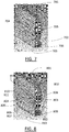
- the Fig. 2 shows an example of projection of the cutoff line 109 of the light beam by projection on the input diopter of the lens 102.
- central zone 104 extends on either side of the projection of the cutoff line 109 on the input diopter of the lens 102: this means that the central zone may include the projection of the cut line, and that the limits of this zone may be at (non-zero) distances from this projection.
- the distances, noted 110 and 111 on the Fig. 2 are the distances between the limits of the central zone and the intersection 113 of projections two axes composing the cutoff line. In the complex case where the cutoff line extends along more than two axes, all the projections of the intersections of the axes of the cutoff can be located at a non-zero distance from the limits of the central zone.
- the two axes may be at non-zero distances from the limits of the central zone.
- the sum of these two distances 110, 111 forms a height h of the central zone.
- the height is defined with respect to the x axis.
- This zone can also extend along the image of the cut line: this means, as illustrated on the Fig. 2 , the central zone may include integrally the projection of the cut line on the diopter of the lens 102.
- the central zone thus extends in the horizontal direction (x-axis) with a distance 112, and in a vertical direction (y-axis) along at least a distance 110, 111.
- This central zone makes it possible to limit the quantity of elements diffractive to be placed on the lens 102. Therefore, the output intensity of the light module is increased.
- the central zone is dimensioned so that the chromatism of the cut line is not visible. Indeed, as explained above, the dispersion phenomenon is weak near the optical axis and increases as the incident rays are close to the edges of the lens. Thus, if a central zone (including the optical axis) is selected which is sufficiently small, the dispersion phenomenon, and thus the chromatic dispersion angle of this zone, is so small that it is not visible to the driver or other users.
- the central zone is preferably sized as large as possible, it being understood that the central zone is dimensioned so that it makes it possible to obtain a chromatic break. whose chromaticism can not be distinguished with the naked eye.
- the central area size is sized so that the chromatic dispersion angle of the central area is not visible. In this way, the output intensity is maximized.
- the central zone may advantageously be dimensioned so that the chromatic dispersion angle of the central zone is less than or equal to half the transition angle of the chromatic cleavage.
- Fig. 6 which schematizes the influence of the variation of the chromatic dispersion angle of the central zone; the angle of transition is the same as the one on the Fig. 5 .
- the cutoff line 503 characterized by a transition angle 506, separating an illuminated zone 501 from a dark zone 502, and the zone 507 around the cutoff line, where the chromatism is observable.
- the reduction of the dispersion angle of the central zone makes it possible to reduce the size of the colored zone 507, transition of the dark area to the illuminated area.
- the reduction of the dispersion angle of the central zone is obtained by decreasing at least one of the distances 110 and 111 illustrated in FIG. Fig. 2 that is, the height of the central area (relative to the y axis) is decreased.
- the reduction of the chromatic dispersion angle of the central zone makes it possible to reduce the visibility of the chromaticism of the cut line by the drivers and the other users.
- the transition angle of the cut 506 may range from 0.1 ° to 3 ° (degrees) depending on the regulation, including terminals, and preferably between 0.25 ° and 0.3 ° inclusive.
- the lens 102 has two diopters; a first diopter is plane and the second diopter is convex.
- Diffractive elements 106 are arranged on the flat surface such that a central zone 104 is devoid of diffractive elements. The diffractive elements are therefore arranged in the zones 107 and 105, and delimit the central zone 104. Thus, the diffractive elements may be positioned on at least one edge surrounding said central zone.
- the diffractive elements are arranged to be substantially parallel to the cut. This means that the inclination of the diffractive elements with respect to the cut-off line is thus less than or equal to 25 °, and preferably less than or equal to 18 °.
- the diffractive elements are arranged substantially parallel to an axis of these axes in which the cut extends.
- the cutoff line includes a horizontal segment (along the x axis on the FIG; 2 )
- the diffractive elements are arranged substantially parallel along this horizontal axis.
- the lens 701 carries diffractive elements arranged so as to form lines of diffractive elements 703.
- the lines of diffractive elements are arranged in the zones 705 and 706, which delimit the central zone 702 devoid of diffractive elements.
- the central zone 702 is represented on the Fig. 2 by the white dots.
- the Fig. 7 also illustrates the possibility that the area occupied by the central area 702 may be smaller in size than the optimal size of the central area, such as that shown in FIG. Fig. 2 .
- a line of diffractive elements has several diffractive elements that are aligned with each other. These lines are preferably rectilinear, that is to say that they have a shape close to a part of a line.
- the lines of diffractive elements may also have a curved shape, or may be in the form of a wave that may be similar to a sinusoidal shape of small amplitude. In any case, when the lines are not straight, their shape must make it possible to correct the chromaticism of the cut in the vertical direction (denoted x on the Fig. 7 ).
- the arrangement of these diffractive elements is called the diffraction pattern 704.
- the diffraction pattern is chosen according to the dispersive power of the lenses, and thus depends on their shapes and their materials. In the case of the configuration represented by the Fig.
- the diffraction pattern corrects the chromaticism of the projected cut in the vertical direction (the x-axis) previously mentioned.
- This correction is thus adapted to the chromaticism of the light devices of motor vehicles, that is to say that it is adapted to correction of chromaticism along the vertical axis of the beams with horizontal cut-off line.
- the power of correction of the chromatism of the cutoff line by a diffraction pattern depends on the intervals which separate the shapes of the diffraction pattern.
- the diffraction efficiency depends on the shape of the diffraction pattern, as well as the height of the diffractive elements.
- the diffraction efficiency is a value that reflects the extent of diffracted light energy that can be obtained with respect to incident light energy. In other words, a low diffraction efficiency results in a loss and diffusion of light from the light source of the light module.
- height of the diffractive elements is meant the thickness of these elements along an axis z, perpendicular to the x and y axes.
- the diffractive elements are arranged so as to correct the chromatism of the cutoff line along the vertical axis.
- the interval, also called the step, separating the forms of the diffractive elements is the distance separating two successive forms of diffractive elements.
- the Fig. 9 illustrates the use of lines as a diffraction pattern: the diffractive elements are aligned and thus form lines of diffractive elements. Lines 902 of diffractive elements are disposed on a diopter of the lens 901, more precisely on the zones 905 and 906 which surround the central zone 903 devoid of diffractive elements. The distance between the successive lines of diffractive elements 904 is in this example the same for all the lines of diffractive elements. It is possible to set the steps 904 so that the correction power of the diffraction pattern is adapted to the chromatic dispersion angle of the zones.
- the dispersion phenomenon is weak near the optical axis and accentuates at the edges of the lens.
- the chromatic dispersion angle of these zones is thus higher than that of the central zone: it is thus possible to vary the distance between two successive lines of diffractive elements in such a way that the step corrects the chromatic dispersion angle of the area delimited by the lines of successive diffractive elements. This example is illustrated by the Fig. 8 .
- the Fig. 8 illustrates an example in which the distances separating two lines of successive diffractive elements vary.
- the lines of diffractive elements 802 are disposed on a diopter of the lens 801 so that the central zone 803 is devoid of diffractive elements.
- the distance 804 is a step close to the central zone and the distance 805 is a step close to the edges of the lens.
- An area 806 is delimited by the lines of successive diffractive elements 810 and 811 which are separated by the step 804.
- This zone 806 has a chromatic dispersion angle which is smaller than that of the zone 807 delimited by the lines of diffractive elements.
- successive 812 and 813 separated by a step 805. The proximity of the zone 807 of the edges of the lens causes this difference.
- the step calculated for the correction of the chromatic dispersion angle of the zone 806 is thus smaller than the calculated step for the correction of the chromatic dispersion angle of the zone 807.
- the step 804 is larger than the pitch 805: this thus allows the step is adapted to the correction of the dispersion phenomenon of the zone 806 between the lines 810 and 811 which is lower than in the zone 807 delimited by the lines 812 and 813.
- the step between the lines of successive diffractive elements vary according to the chromatic dispersion angles associated with the zones delimited by these lines.
- the variation of the distance between the lines of successive elements increases as the lines of diffractive elements are close to the central zone. Increasing the distance between the element lines makes it possible to increase the diffraction efficiency, while ensuring an adequate correction of the dispersion phenomenon.
- the variation of the pitch can be the same in the zones 808 and 809 where the lines of diffractive elements are arranged and which delimit the central zone 803.
- the Fig. 10 to 12 illustrate examples in which the diffractive elements 1002, 1102 and 1202 may be disposed on the input diopter or on the output diopter of the lens or lenses of the light module.
- the Fig. 10 illustrates an example of a light module according to the invention. It is composed of a light source 1001, a lens 1004 which comprises a plane entry diopter and a convex exit diopter. Diffractive elements 1002 are arranged towards the edges of the convex exit diopter, that is to say a central zone 1003 is devoid of diffractive elements.
- This embodiment makes it possible to reduce the intensity losses associated with the diffractive elements.
- the provision on the convex exit diopter of a lens 1004 makes it possible to increase the luminous intensity at the output of the light module.
- the example of light module of the Fig. 11 is composed of a light source 1101, a convex lens 1105 with a plane entry diopter, on which diffractive elements 1102 are arranged on either side of the central zone 1104 which is devoid of diffractive elements.
- the central zone 1104 without diffractive elements has a cylindrical optical power 1103.
- the cylindrical optical power designates the optical power of a cylindrical lens.
- a cylindrical lens has a zero optical power in the X direction and non-zero in the Y direction of the reference 2000.
- the diopter is modified at the central area to obtain an optical power similar to an optical power of a lens cylindrical.
- a curvature of the diopter can be added at the level of the central zone.
- This cylindrical optical power given by 1103 makes it possible to reduce the deviation difference of the rays passing through the central zone with respect to those passing through the zones covered with diffractive elements. Indeed, the diffractive elements arranged on the lens or the lenses of the module deviate the trajectory of the transmitted rays with respect to the transmitted rays in the absence of the diffractive.
- the Fig. 12 illustrates a configuration in which the light module comprises three light sources 1201, an optical system comprising two lenses 1205 and 1206.
- the diffractive elements 1202 are disposed on the exit diopter of the first lens 1205, so that a central zone 1204 is devoid of diffractive elements.
- a convergent lens 1203 is disposed on the input diopter of the lens 1204 on which the diffractive elements 1202 are disposed.
- the convergent lens 1203 is contiguous with the lens 1204 to ensure the continuity of the deflection of the rays at the central zone 1204 devoid of diffractive elements.
- the lens 1206 receives the light rays from the lens 1205 and forms the light beam emitted by the light module.
- the diffractive elements can be made on a film by rolling process.
- the film is a layer of a transparent solid material.
- the film can be a transparent plastic film.
- transparent material is meant any material whose light transmission is greater than 60%.
- the diffractive elements, which may be raised marks, may be made by rolling, that is to say by the plastic deformation of the film.
- the film comprising one of the diffraction patterns discussed, is placed on one of the lenses of the light module. In other words, the film is applied to the surface of the lens, so as to be fixed to the diopter of the lens.
- This fixing can be done using an adhesive, for example a polymerizable adhesive which polymerizes following brief exposure to UV light.
- the film can be a sticker film.
- the rolling method is particularly advantageous for producing lines of diffractive elements.
- the pattern comprises lines
- the manufacture of a film as described above is facilitated, compared for example with circular diffraction patterns.
- the light modules described are incorporated in light devices that can be used as low beam, high beam or fog lamp. Such light devices can integrate one or more versions of the light module, that is to say, designed according to different embodiments.
Landscapes
- Engineering & Computer Science (AREA)
- General Engineering & Computer Science (AREA)
- Physics & Mathematics (AREA)
- Microelectronics & Electronic Packaging (AREA)
- Optics & Photonics (AREA)
- Mechanical Engineering (AREA)
- Non-Portable Lighting Devices Or Systems Thereof (AREA)
- Lighting Device Outwards From Vehicle And Optical Signal (AREA)
Abstract
Il est proposé un module lumineux (100) pour véhicule automobile. Le module lumineux comprend au moins un moteur lumineux (101) configuré pour former un faisceau lumineux à ligne de coupure qui s'étendant suivant un ou plusieurs axes, et au moins une lentille (102) apte à projeter le faisceau lumineux à ligne de coupure. La lentille comprend des éléments diffractifs (106) qui corrigent tout ou partie du chromatisme de la lentille, et elle comprend une zone centrale (104) qui est dépourvue des éléments diffractifs.

Description
L'invention se rapporte au domaine des dispositifs lumineux de véhicule automobile, c'est-à-dire des dispositifs d'éclairage avant et arrière, permettant de projeter un faisceau lumineux pour éclairer la route. Les feux de croisement et/ou de routes sont des exemples de tels dispositifs lumineux. L'invention porte plus précisément sur les modules lumineux constitutifs des dispositifs lumineux.The invention relates to the field of light devices of a motor vehicle, that is to say, front and rear lighting devices for projecting a light beam to illuminate the road. The low beam and / or road lights are examples of such light devices. The invention relates more precisely to the constituent light modules of the light devices.
La projection d'un faisceau lumineux par un dispositif lumineux de véhicule automobile, tels que des projecteurs avants ou feux arrières, permet classiquement d'éclairer la route avec un éclairage global et ainsi d'augmenter la visibilité en cas d'obscurité, par exemple de nuit. Cela permet une conduite sécurisée du véhicule. Ces dispositifs lumineux peuvent comprendre un ou plusieurs modules lumineux.The projection of a light beam by a light device of a motor vehicle, such as headlights or rear lights, conventionally allows to illuminate the road with global lighting and thus to increase visibility in case of darkness, for example by night. This allows secure driving of the vehicle. These light devices may comprise one or more light modules.
La règlementation impose que les faisceaux lumineux projetés par les modules lumineux comportent une coupure pour ne pas éblouir les autres usagers. Cette coupure, qui se matérialise sous la forme d'une « ligne de coupure », crée une zone de transition entre une zone éclairée et une zone sombre. La forme de la ligne de coupure est généralement soumise à une règlementation, par exemple la règlementation ECE n°48 en Europe ou la réglementation FMVSS 108 aux États-Unis d'Amérique.The regulation requires that the light beams projected by the light modules have a cutoff so as not to dazzle other users. This cut, which materializes in the form of a "cut line", creates a transition zone between a lighted area and a dark area. The shape of the cut-off line is generally subject to regulation, for example ECE Regulation No. 48 in Europe or FMVSS
Lors de la projection d'un faisceau lumineux à ligne de coupure par un module lumineux classique, on observe une coloration au niveau de la zone de transition. Cette observation résulte du phénomène de dispersion chromatique de la lumière et de la nature dispersive des composants optiques intégrés dans le module lumineux. En pratique, la principale conséquence de ce phénomène est que les phares projetant un faisceau de lumière blanche apparaissent bleus pour les autres usagers; ce phénomène est appelé chromatisme. En outre, ce chromatisme s'avère gênant pour les conducteurs.When a cut-off light beam is projected by a conventional light module, color is observed at the transition zone. This observation results from the phenomenon of chromatic dispersion of the light and the dispersive nature of the optical components integrated in the light module. In practice, the main consequence of this phenomenon is that headlights projecting a beam of white light appear blue for other users; this phenomenon is called chromaticism. In addition, this chromaticism is inconvenient for drivers.
Une solution connue est d'utiliser par exemple un système achromatique composé d'éléments diffractifs circulaires concentriques. Ces éléments diffractifs permettent la correction du chromatisme de la ligne de coupure selon plusieurs directions. Néanmoins, cette solution nécessite une quantité importante d'éléments diffractifs, c'est-à-dire qu'une grande partie de la lentille doit ainsi être recouverte par ces éléments diffractifs. Ainsi, un module lumineux comprenant une lentille avec de tels éléments diffractifs circulaires concentriques présente une efficacité de diffraction limitée qui résulte en une perte et une diffusion de la lumière de la source lumineuse. De plus, les éléments diffractifs concentriques font apparaitre des tâches de diffraction due aux autres ordres de diffraction dans la zone sombre : ces tâches sont gênantes, notamment pour les autres usagers. En outre, plus la quantité d'éléments diffractifs est importante, plus le système est complexe à fabriquer, ce qui augmente son coût de fabrication.A known solution is to use for example an achromatic system composed of concentric circular diffractive elements. These diffractive elements allow the correction of the chromaticism of the cutoff line in several directions. Nevertheless, this solution requires a large amount of diffractive elements, that is to say that a large part of the lens must thus be covered by these diffractive elements. Thus, a light module comprising a lens with such concentric circular diffractive elements has limited diffraction efficiency which results in loss and scattering of light from the light source. In addition, the concentric diffractive elements show diffraction tasks due to other diffraction orders in the dark zone: these tasks are troublesome, especially for other users. In addition, the larger the amount of diffractive elements, the more complex the system is to manufacture, which increases its cost of manufacture.
Dans ce contexte, il existe un besoin pour améliorer la projection d'un faisceau lumineux à ligne de coupure et faciliter la fabrication de l'élément diffractif.In this context, there is a need to improve the projection of a cut-off light beam and to facilitate the fabrication of the diffractive element.
A cette fin, il est proposé un module lumineux pour véhicule automobile. Le module comprend au moins un moteur lumineux configuré pour former un faisceau lumineux à ligne de coupure, la ligne de coupure s'étendant suivant un ou plusieurs axes. Le module comprend en outre au moins une lentille apte à projeter ledit faisceau lumineux à ligne de coupure, ladite au moins une lentille comprenant des éléments diffractifs pour corriger tout ou partie du chromatisme de la lentille, et comprenant une zone centrale qui est dépourvue desdits éléments diffractifs.For this purpose, it is proposed a light module for a motor vehicle. The module comprises at least one light engine configured to form a light line beam, the cut line extending along one or more axes. The module further comprises at least one lens capable of projecting said cut-off light beam, said at least one lens comprising diffractive elements for correcting all or part of the chromaticism of the lens, and comprising a central zone which is devoid of said elements. diffractive.
Selon différents exemples, le dispositif lumineux peut comprendre l'une ou plusieurs des caractéristiques suivantes combinées entre elles :
- la zone centrale s'étend de part et d'autre et le long d'une projection de ladite ligne de coupure sur ladite au moins une lentille ;
- les éléments diffractifs sont positionnés sur au moins un bord entourant ladite zone centrale de ladite au moins une lentille ;
- la zone centrale s'étend de sorte qu'un angle de dispersion chromatique de la lumière émise par le moteur lumineux en sortie de la zone centrale est inférieur ou égal à la moitié d'un angle de la transition de la ligne de coupure ;
- l'angle de la transition de la ligne de coupure est compris entre 0,1° et 3° bornes incluses, de préférence entre 0,25° et 0,3° bornes incluses ;
- les éléments diffractifs sont sensiblement parallèles à la ligne de coupure ;
- les éléments diffractifs sont agencés pour former des lignes d'éléments diffractifs, les lignes d'éléments diffractifs étant sensiblement rectilignes et parallèles entre elles ;
- les distances séparant deux lignes d'éléments diffractifs successives sont identiques ;
- la distance entre deux lignes d'éléments diffractifs successives dépend de la position des deux lignes d'éléments diffractifs successives par rapport à la zone centrale ;
- la distance entre deux lignes d'éléments diffractifs successives est calculée en fonction de la matière et de la forme de la lentille ;
- les éléments diffractifs sont positionnés sur un dioptre d'entrée ou un dioptre de sortie de ladite au moins une lentille ;
- la zone centrale a une puissance optique cylindrique ;
- un film comprend les éléments diffractifs et est posé sur ladite au moins une lentille ;
- le film est obtenu par un procédé de laminage ;
- lesdites une ou plusieurs sources lumineuses sont des sources électroluminescentes.
- the central zone extends on either side and along a projection of said cut line on said at least one lens;
- the diffractive elements are positioned on at least one edge surrounding said central zone of said at least one lens;
- the central zone extends such that a chromatic dispersion angle of the light emitted by the light engine at the output of the central zone is less than or equal to half of an angle of the transition of the cutoff line;
- the angle of transition of the cut-off line is between 0.1 ° and 3 ° inclusive, preferably between 0.25 ° and 0.3 ° inclusive;
- the diffractive elements are substantially parallel to the cutoff line;
- the diffractive elements are arranged to form lines of diffractive elements, the lines of diffractive elements being substantially rectilinear and parallel to each other;
- the distances separating two lines of successive diffractive elements are identical;
- the distance between two lines of successive diffractive elements depends on the position of the two lines of successive diffractive elements with respect to the central zone;
- the distance between two lines of successive diffractive elements is calculated as a function of the material and the shape of the lens;
- the diffractive elements are positioned on an input diopter or an output dioptre of said at least one lens;
- the central zone has a cylindrical optical power;
- a film comprises the diffractive elements and is placed on said at least one lens;
- the film is obtained by a rolling process;
- said one or more light sources are electroluminescent sources.
Il est également proposé un dispositif lumineux comprenant au moins un module lumineux. Le dispositif lumineux peut exécuter une fonction choisie parmi une fonction de feu de croisement, une fonction de feu de route, une fonction de feu de brouillard.It is also proposed a light device comprising at least one light module. The light device can perform a function selected from a low beam function, a high beam function, a fog lamp function.
Différents modes de réalisation de l'invention vont maintenant être décrits, à titre d'exemples nullement limitatifs, en se référant aux dessins annexés dans lesquels :
-
FIG. 1 illustre un premier exemple de module lumineux selon l'invention ; -
FIG. 2 illustre un exemple de lentille avec des éléments de diffraction selon l'invention ; -
FIG. 3 illustre un exemple d'image projetée d'un faisceau lumineux à ligne de coupure ; -
FIG. 4 illustre schématiquement un exemple du phénomène de dispersion chromatique ; -
FIG. 5 illustre schématiquement un exemple du phénomène de dispersion chromatique localisé sur la ligne de coupure du faisceau lumineux à ligne de coupure illustré sur laFIG. 2 ; -
FIG. 6 illustre schématiquement un exemple de l'effet de la réduction de l'angle de dispersion chromatique sur le phénomène de dispersion chromatique visible sur laFIG. 5 ; -
FIG. 7 illustre un exemple de motif de diffraction selon l'invention ; -
FIG. 8 illustre un autre exemple de motif de diffraction selon l'invention ; -
FIG. 9 illustre un autre exemple de motif de diffraction selon l'invention ; -
FIG. 10 illustre un exemple de module lumineux selon l'invention comportant des éléments diffractifs sur le dioptre de sortie de la lentille ; -
FIG. 11 illustre un exemple de module lumineux selon l'invention comportant des éléments diffractifs sur le dioptre d'entrée de la lentille ; -
FIG. 12 illustre un exemple de module lumineux selon l'invention.
-
Fig. 1 illustrates a first example of a light module according to the invention; -
Fig. 2 illustrates an example of a lens with diffraction elements according to the invention; -
Fig. 3 illustrates an example of a projected image of a cut-off light beam; -
Fig. 4 schematically illustrates an example of the chromatic dispersion phenomenon; -
Fig. 5 schematically illustrates an example of the phenomenon of chromatic dispersion localized on the cutoff line of the cutoff light beam illustrated on FIG.Fig. 2 ; -
Fig. 6 schematically illustrates an example of the effect of the reduction of the chromatic dispersion angle on the visible chromatic dispersion phenomenon on theFig. 5 ; -
Fig. 7 illustrates an example of a diffraction pattern according to the invention; -
Fig. 8 illustrates another example of a diffraction pattern according to the invention; -
Fig. 9 illustrates another example of a diffraction pattern according to the invention; -
Fig. 10 illustrates an example of a light module according to the invention comprising diffractive elements on the exit diopter of the lens; -
Fig. 11 illustrates an example of a light module according to the invention comprising diffractive elements on the input diopter of the lens; -
Fig. 12 illustrates an example of a light module according to the invention.
On propose un module lumineux pour véhicule automobile, ainsi qu'un dispositif lumineux comprenant une ou plusieurs versions d'un tel module lumineux. Ce dispositif lumineux projette un faisceau lumineux sur une scène. La scène ou « scène de route » est l'environnement du véhicule susceptible d'être éclairé par le dispositif lumineux. Un tel dispositif lumineux est apte à exécuter les fonctions de feu de croisement et/ou de feu de route et/ou de feu de brouillard.There is provided a light module for a motor vehicle, and a light device comprising one or more versions of such a light module. This light device projects a light beam onto a scene. The scene or "road scene" is the environment of the vehicle likely to be illuminated by the light device. Such a light device is able to perform the functions of low beam and / or high beam and / or fog lamp.
Le module lumineux selon l'invention est adapté aux véhicules automobiles pouvant être tout type de véhicule terrestre, par exemple une automobile voiture, une motocyclette, ou un camion. Le véhicule peut être équipé d'un ou plusieurs projecteurs avant et/ou d'un ou plusieurs projecteurs arrière. L'un ou plusieurs des projecteurs avant et/ou arrière peuvent comprendre chacun un ou plusieurs dispositifs lumineux configurés chacun pour projeter un faisceau lumineux.The light module according to the invention is suitable for motor vehicles that can be any type of land vehicle, for example a car automobile, a motorcycle, or a truck. The vehicle may be equipped with one or more front projectors and / or one or more rear projectors. One or more of the front and / or rear headlamps may each comprise one or more light devices each configured to project a light beam.
La
Le module lumineux 100 comprend une ou plusieurs sources lumineuses 101 qui émettent des rayons lumineux, par exemple de la lumière blanche. Les sources lumineuses peuvent être des sources lumineuses à filament, à plasma, ou encore à gaz. Les sources lumineuses peuvent également être des sources électroluminescentes acronyme de l'anglais « solid-state lighting » qui comprennent des éléments électroluminescents. Les éléments électroluminescents sont situés sur un même substrat, et de préférence sur une même face du substrat qui peut être par exemple du saphir ou encore du silicium. Les éléments électroluminescents sont déposés sur ou s'étendent à partir au moins une face du substrat. Un élément électroluminescent peut-être, mais n'est pas limité à, une diode électroluminescente LED, une diode électroluminescente organique OLED, une diode électroluminescente polymérique PLED. Ainsi, on comprend que toute source lumineuse répondant aux éventuelles contraintes règlementaires du domaine automobile et apte à émettre des rayons lumineux peut être utilisée.The
La ou les sources lumineuses comprises dans le module lumineux selon l'invention sont des éléments d'un moteur lumineux. Un moteur lumineux est un dispositif connu qui forme un faisceau lumineux à ligne de coupure. Il peut ainsi comprendre une ou plusieurs sources lumineuses, un réflecteur et une plieuse. La plieuse permet de former une ligne de coupure qui respecte les contraintes règlementaires, comme connu dans l'art. Le réflecteur comprend un ou plusieurs miroirs et permet de modifier, par réflexion, la répartition spatiale du rayonnement de la ou les sources lumineuses de sorte à créer un faisceau lumineux. De manière générale, le module lumineux selon l'invention comprend au moins un moteur lumineux.The light source or sources included in the light module according to the invention are elements of a light engine. A light engine is a known device that forms a light beam with a cutoff line. It can thus include one or more light sources, a reflector and a folder. The folder makes it possible to form a cut line that complies with the regulatory constraints, as known in the art. The reflector comprises one or more mirrors and makes it possible to modify, by reflection, the spatial distribution of the radiation of the light source or sources so as to create a light beam. In general, the light module according to the invention comprises at least one light engine.
Le module lumineux 100 comprend également une ou plusieurs lentilles 102. Les une ou plusieurs lentilles forment un système optique et elles orientent les rayons lumineux émis par le moteur lumineux de telle sorte à obtenir en sortie du module lumineux un faisceau lumineux, e.g. un faisceau lumineux pour éclairer la scène dans laquelle évolue un véhicule automobile qui comporterait le module lumineux. Une lentille est un milieu transparent limité par des dioptres (par exemple un dioptre d'entré et un dioptre de sortie) qui peuvent être par exemple plans, convexes, ou concaves. Le terme dioptre désigne les surfaces séparant le milieu de la lentille, par exemple le verre, avec le milieu dans lequel se trouve la lentille, par exemple l'air. La terminologie « dioptre d'entrée » désigne le premier dioptre d'une lentille rencontré par les rayons lumineux qui vont traverser cette lentille. Par analogie, le « dioptre de sortie » désigne le dernier dioptre d'une lentille rencontré par les rayons lumineux qui ont traversé cette lentille. Comme illustré sur la
La ou les lentilles du module lumineux sont aptes à projeter un faisceau lumineux à ligne de coupure sur la scène. Un exemple d'image projetée d'un faisceau lumineux à ligne de coupure 300 est illustré sur le
Toujours dans l'exemple de la
Ainsi, lorsqu'une ligne de coupure s'étend suivant deux axes, comme les exemples des
On observe, sur l'image projetée d'un faisceau lumineux à ligne de coupure, un chromatisme de la ligne de coupure. Cela signifie que la transition entre la zone éclairée et la zone sombre apparait colorée. Le chromatisme de la ligne de coupure résulte du phénomène connu de dispersion.On the projected image of a light beam with a cut-off line, a chromaticism of the cut-off line is observed. This means that the transition between the lighted area and the dark area appears colorful. The chromaticism of the cutoff line results from the known phenomenon of dispersion.
Le phénomène de dispersion est un phénomène observable pour tous les milieux transparents, à l'exception du vide. Ce phénomène est illustré sur la
Ainsi, le phénomène de dispersion d'une lumière passant à travers une lentille dépend du spectre composant la lumière, de la matière et de la forme des lentilles. En effet, le phénomène de dispersion implique nécessairement une lumière incidente polychromatique : dans le domaine de l'automobile, la ou les sources lumineuses émettent en général une lumière blanche. De plus, l'angle de dispersion chromatique dépend de la forme de la lentille qui peut être par exemple convexe, concave, ménisque, et de la matière de la lentille qui peut comprendre du verre, un polymère ou un cristal. Le phénomène de dispersion s'amplifie à mesure que les rayons lumineux incidents sont proches des bords de la lentille. En pratique, on observe que plus on s'éloigne de l'axe optique, et donc plus on se rapproche des bords de la lentille, plus le phénomène de dispersion est visible. Par exemple, le bord d'une lentille est la surface 108 représentée sur la
Le chromatisme de la ligne de coupure est schématisé sur la
- l'image projetée du moyen permettant de former la ligne de coupure par les rayons de longueur d'onde la plus faible 504 de la lumière incidente émise par la ou les sources lumineuses du module lumineux. Dans le cas d'une source lumineuse émettant de la lumière blanche, il s'agit de l'image de la ligne de coupure par les rayons bleus. Dans ce cas, cette image est par conséquent bleue.
- l'image projetée du moyen permettant de former la ligne de coupure par les rayons de longueur d'onde la plus élevée 505 de la lumière incidente émise par la ou les sources lumineuses du module lumineux. Dans le cas d'une source lumineuse émettant de la lumière blanche, il s'agit de l'image de la ligne de coupure par les rayons rouges. Dans ce cas, cette image est par conséquent rouge.
- the projected image of the means making it possible to form the cutoff line by the weakest wavelength rays 504 of the incident light emitted by the light source (s) of the light module. In the case of a light source emitting white light, it is the image of the cut line by the blue rays. In this case, this image is therefore blue.
- the projected image of the means for forming the cutoff line by the highest wavelength rays 505 of the incident light emitted by the light source (s) of the light module. In the case of a light source emitting white light, it is the image of the cut line by the red rays. In this case, this image is therefore red.
Sans le phénomène de dispersion discuté précédemment, les deux images 504 et 506 de la ligne de coupure auraient été superposées. L'image issue des rayons bleus est en général la plus visible, et elle est à l'origine la perception par les autres usagers de la teinte bleue dans la lumière émise par les phares.Without the dispersion phenomenon previously discussed, the two
Le chromatisme de la ligne de coupure, issu du phénomène de dispersion, se déroule suivant toutes les directions et est donc observable selon plusieurs directions. Les modules lumineux de l'art antérieur soit ne corrigent pas le chromatisme de la ligne de coupure soit corrigent le chromatisme de la ligne de coupure de manière équivalente selon toutes ces directions.The chromaticism of the cutoff line, resulting from the phenomenon of dispersion, unfolds in all directions and is therefore observable in several directions. The light modules of the prior art either do not correct the chromaticism of the cutoff line or correct the chromatism of the cutoff line equally in all these directions.
Pour réduire ce phénomène, le module lumineux selon l'invention comprend des éléments diffractifs 106 positionnés sur au moins une des lentilles 102. Les éléments diffractifs sont des figures, telles que des marques transparentes en relief. Ces éléments diffractifs sont positionnés sur au moins une des lentilles du module lumineux, c'est-à-dire qu'ils sont disposés sur le dioptre d'entrée d'au moins une lentille, et/ou sur son dioptre de sortie. Le positionnement des éléments diffractifs est réalisé de manière à ne corriger le chromatisme que selon une direction sensiblement unique. En effet, le chromatisme n'est visible et gênant pour le conducteur et les autres usagers que lorsqu'il se propage selon un axe qui est noté axe y. Cet axe y est identifié sur la
Le module lumineux comprend également une zone centrale 104 sur la ou les lentilles. Cette zone centrale est dépourvue d'éléments diffractifs. La zone centrale peut s'étendre de part et d'autre et le long de la projection de la ligne de coupure sur un des dioptres d'une de(des) lentille(s) du module lumineux selon l'invention. La projection de la ligne de coupure sur un des dioptres de la lentille est l'image formée par la ligne de coupure sur un des dioptres de la lentille. La
La zone centrale est dimensionnée de telle sorte que le chromatisme de la ligne de coupure ne soit pas visible. En effet, comme expliqué précédemment, le phénomène de dispersion est faible près de l'axe optique et augmente à mesure que les rayons incidents sont proches des bords de la lentille. Ainsi, si on sélectionne une zone centrale (comprenant l'axe optique), suffisamment petite, le phénomène de dispersion, et donc l'angle de dispersion chromatique de cette zone, est tellement faible, qu'il n'est pas visible par le conducteur ou les autres usagers. Afin d'augmenter l'intensité lumineuse en sortie du module lumineux selon l'invention, la zone centrale est de préférence dimensionnée la plus grande possible, étant entendu que la zone centrale est dimensionnée de sorte qu'elle permet d'obtenir une coupure chromatique dont le chromatisme ne peut être distingué à l'oeil nu. En d'autres termes, la taille de zone centrale est dimensionnée de telle sorte que l'angle de dispersion chromatique de la zone centrale ne soit pas visible. De cette façon, l'intensité de sortie est maximisée.The central zone is dimensioned so that the chromatism of the cut line is not visible. Indeed, as explained above, the dispersion phenomenon is weak near the optical axis and increases as the incident rays are close to the edges of the lens. Thus, if a central zone (including the optical axis) is selected which is sufficiently small, the dispersion phenomenon, and thus the chromatic dispersion angle of this zone, is so small that it is not visible to the driver or other users. In order to increase the luminous intensity at the output of the light module according to the invention, the central zone is preferably sized as large as possible, it being understood that the central zone is dimensioned so that it makes it possible to obtain a chromatic break. whose chromaticism can not be distinguished with the naked eye. In other words, the central area size is sized so that the chromatic dispersion angle of the central area is not visible. In this way, the output intensity is maximized.
Dans ce but, la zone centrale peut avantageusement être dimensionnée de telle sorte que l'angle de dispersion chromatique de la zone centrale est inférieur ou égal à la moitié de l'angle de transition de la coupure chromatique. Ceci est illustré par la
Différents exemples du positionnement des éléments diffractifs utilisés dans le module lumineux sont maintenant discutés en référence des
Dans l'exemple représentée en
Dans l'exemple représenté sur la
Le pouvoir de correction du chromatisme de la ligne de coupure par un motif de diffraction dépend des intervalles qui séparent les formes du motif de diffraction. L'efficacité de diffraction dépend de la forme du motif de diffraction, ainsi que de la hauteur des éléments diffractifs. L'efficacité de diffraction est une valeur qui traduit l'étendue de l'énergie de la lumière diffractée pouvant être obtenue par rapport à une énergie de lumière incidente. En d'autres termes, une faible efficacité de la diffraction se traduit par une perte et une diffusion de la lumière de la source lumineuse du module lumineux. Par hauteur des éléments diffractifs, on entend l'épaisseur de ces éléments selon un axe z, perpendiculaire aux axes x et y. Comme expliqué précédemment, les éléments diffractifs sont agencés de sorte à corriger le chromatisme de la ligne de coupure selon l'axe verticale. L'intervalle, aussi appelé le pas, séparant les formes des éléments diffractifs est la distance séparant deux formes successives d'éléments diffractifs. La
De manière générale, plus la distance entre les lignes d'éléments diffractifs est faible, c'est-à-dire plus le pas est faible, plus le pouvoir de correction sera adapté aux grands angles de dispersion. Comme évoqué plus tôt, le phénomène de dispersion est faible près de l'axe optique et s'accentue aux bords de la lentille. Dans les zones localisées près des bords de la lentille, l'angle de dispersion chromatique de ces zones est donc plus élevé que celui de la zone centrale : il est ainsi possible de faire varier la distance entre deux lignes successives d'éléments diffractifs de manière à ce que le pas corrige l'angle de dispersion chromatique de la zone délimitée par les lignes d'éléments diffractifs successives. Cet exemple est illustré par la
La
Les
La
L'exemple de module lumineux de la
L'ajout de puissance optique via la modification du dioptre d'entrée de la lentille pour réduire la différence de déviation introduite par les éléments diffractifs est compatible avec une disposition des éléments diffractifs sur le dioptre d'entrée ou de sortie d'une ou plusieurs lentilles du module lumineux. Par exemple, la
Les éléments diffractifs peuvent être réalisés sur un film par procédé de laminage. Le film est une couche d'un matériau solide transparent. Le film peut être un film plastique transparent. On entend par matériau transparent tout matériau dont la transmission lumineuse est supérieure à 60%. Les éléments diffractifs, pouvant être des marques en reliefs, peuvent être réalisés par laminage, c'est-à-dire par la déformation plastique du film. Ainsi, plusieurs éléments diffractifs sont réalisés sur une portion de film, selon les différentes dispositions détaillées dans les modes de réalisation décrits précédemment. Le film, comprenant un des motifs de diffraction discutés, est posé sur une des lentilles du module lumineux. En d'autres termes, le film est appliqué sur la surface de la lentille, de manière à être fixé au dioptre de la lentille. Cette fixation peut se faire à l'aide d'une colle, par exemple une colle polymérisable qui se polymérise suite à l'exposition brève à une lumière UV. Le film peut être un film autocollant. Dans un même module, il est possible qu'un tel film, comprenant des motifs de diffractions identiques ou similaires, soit apposé sur plusieurs lentilles. Le procédé de laminage est particulièrement avantageux pour fabriquer des lignes d'éléments diffractifs. Notamment, lorsque le motif comprend des lignes, la fabrication d'un film tel que décrit précédemment est facilitée, à comparer par exemple de motifs de diffraction circulaires.The diffractive elements can be made on a film by rolling process. The film is a layer of a transparent solid material. The film can be a transparent plastic film. By transparent material is meant any material whose light transmission is greater than 60%. The diffractive elements, which may be raised marks, may be made by rolling, that is to say by the plastic deformation of the film. Thus, several diffractive elements are made on a portion of film, according to the various detailed provisions in the embodiments described above. The film, comprising one of the diffraction patterns discussed, is placed on one of the lenses of the light module. In other words, the film is applied to the surface of the lens, so as to be fixed to the diopter of the lens. This fixing can be done using an adhesive, for example a polymerizable adhesive which polymerizes following brief exposure to UV light. The film can be a sticker film. In the same module, it is possible for such a film, comprising identical or similar diffraction patterns, to be affixed to several lenses. The rolling method is particularly advantageous for producing lines of diffractive elements. In particular, when the pattern comprises lines, the manufacture of a film as described above is facilitated, compared for example with circular diffraction patterns.
Les modules lumineux décrits sont intégrés à des dispositifs lumineux pouvant être utilisés comme feu de croisement, feu de route ou comme feu de brouillard. De tels dispositifs lumineux peuvent intégrer une ou plusieurs versions du module lumineux, c'est-à-dire conçus selon différents modes de réalisation.The light modules described are incorporated in light devices that can be used as low beam, high beam or fog lamp. Such light devices can integrate one or more versions of the light module, that is to say, designed according to different embodiments.
Claims (17)
Applications Claiming Priority (1)
| Application Number | Priority Date | Filing Date | Title |
|---|---|---|---|
| FR1752313A FR3064339B1 (en) | 2017-03-21 | 2017-03-21 | LIGHT MODULE WITH CHROMATISM CORRECTION |
Publications (1)
| Publication Number | Publication Date |
|---|---|
| EP3379143A1 true EP3379143A1 (en) | 2018-09-26 |
Family
ID=58993049
Family Applications (1)
| Application Number | Title | Priority Date | Filing Date |
|---|---|---|---|
| EP18162952.8A Pending EP3379143A1 (en) | 2017-03-21 | 2018-03-20 | Light module with chromatism correction |
Country Status (4)
| Country | Link |
|---|---|
| US (1) | US10415784B2 (en) |
| EP (1) | EP3379143A1 (en) |
| CN (1) | CN108626686B (en) |
| FR (1) | FR3064339B1 (en) |
Families Citing this family (4)
| Publication number | Priority date | Publication date | Assignee | Title |
|---|---|---|---|---|
| CN112303584A (en) * | 2019-07-31 | 2021-02-02 | 比亚迪股份有限公司 | Lens, car light lens system and car |
| CN111561682A (en) * | 2020-05-18 | 2020-08-21 | 广东烨嘉光电科技股份有限公司 | Automobile headlamp lens and design method thereof |
| CN115046171B (en) * | 2022-08-15 | 2022-10-25 | 常州星宇车灯股份有限公司 | Lens and vehicle lamp with same |
| CN116136294B (en) * | 2023-04-17 | 2023-06-27 | 常州星宇车灯股份有限公司 | Composite lens, manufacturing method thereof, car lamp and manufacturing module of composite lens |
Citations (8)
| Publication number | Priority date | Publication date | Assignee | Title |
|---|---|---|---|---|
| EP1584863A2 (en) * | 2004-04-08 | 2005-10-12 | Schott AG | Lighting device with lens and method of fabricating for such |
| EP1637797A2 (en) * | 2004-09-17 | 2006-03-22 | Hella KGaA Hueck & Co. | Collimator lens for a projecting headlight in a motor vehicle |
| DE102007014676A1 (en) * | 2006-03-29 | 2007-10-04 | Koito Manufacturing Co., Ltd. | Illuminating device for use in vehicle headlamp, has projector lens, which is arranged on optical axis, extends in forward and backward direction of vehicle, and light source is arranged at back side of back focus of projector lens |
| EP1980787A1 (en) * | 2007-04-10 | 2008-10-15 | Koito Manufacturing Co., Ltd. | Lamp unit for vehicle |
| DE102008005488A1 (en) * | 2008-01-22 | 2009-07-23 | Hella Kgaa Hueck & Co. | Headlight for vehicle, has transparent plate attached to optic unit and/or LED field such that light spots forming light distribution is widened in horizontal direction so that adjacent spots lie or overlap together |
| EP2578929A2 (en) * | 2011-10-04 | 2013-04-10 | Automotive Lighting Reutlingen GmbH | Arrangement of overhead elements on a projection lens of a motor vehicle headlamp |
| JP2014175198A (en) * | 2013-03-11 | 2014-09-22 | Stanley Electric Co Ltd | Projector type headlight and projection lens for projector type headlight |
| DE102014112937A1 (en) * | 2014-09-09 | 2016-03-10 | Hella Kgaa Hueck & Co. | Lighting device for vehicles |
Family Cites Families (6)
| Publication number | Priority date | Publication date | Assignee | Title |
|---|---|---|---|---|
| JP5212785B2 (en) * | 2008-02-22 | 2013-06-19 | スタンレー電気株式会社 | Vehicle headlamp |
| EP2322848B1 (en) * | 2009-11-12 | 2017-09-27 | Stanley Electric Co., Ltd. | Vehicle light |
| CN103836484A (en) * | 2014-03-12 | 2014-06-04 | 奇瑞汽车股份有限公司 | Lamplight set of automobile headlamp |
| KR102297128B1 (en) * | 2014-09-22 | 2021-09-02 | 현대모비스 주식회사 | Lamp lens with reduced chromatic aberration and Lamp for vehicle using the same |
| CN204372757U (en) * | 2015-01-28 | 2015-06-03 | 长城汽车股份有限公司 | Car light |
| CN106287403A (en) * | 2015-06-05 | 2017-01-04 | 上海汽车集团股份有限公司 | There is the lamp of reflecting mirror |
-
2017
- 2017-03-21 FR FR1752313A patent/FR3064339B1/en active Active
-
2018
- 2018-03-20 EP EP18162952.8A patent/EP3379143A1/en active Pending
- 2018-03-21 US US15/927,382 patent/US10415784B2/en active Active
- 2018-03-21 CN CN201810235315.2A patent/CN108626686B/en active Active
Patent Citations (8)
| Publication number | Priority date | Publication date | Assignee | Title |
|---|---|---|---|---|
| EP1584863A2 (en) * | 2004-04-08 | 2005-10-12 | Schott AG | Lighting device with lens and method of fabricating for such |
| EP1637797A2 (en) * | 2004-09-17 | 2006-03-22 | Hella KGaA Hueck & Co. | Collimator lens for a projecting headlight in a motor vehicle |
| DE102007014676A1 (en) * | 2006-03-29 | 2007-10-04 | Koito Manufacturing Co., Ltd. | Illuminating device for use in vehicle headlamp, has projector lens, which is arranged on optical axis, extends in forward and backward direction of vehicle, and light source is arranged at back side of back focus of projector lens |
| EP1980787A1 (en) * | 2007-04-10 | 2008-10-15 | Koito Manufacturing Co., Ltd. | Lamp unit for vehicle |
| DE102008005488A1 (en) * | 2008-01-22 | 2009-07-23 | Hella Kgaa Hueck & Co. | Headlight for vehicle, has transparent plate attached to optic unit and/or LED field such that light spots forming light distribution is widened in horizontal direction so that adjacent spots lie or overlap together |
| EP2578929A2 (en) * | 2011-10-04 | 2013-04-10 | Automotive Lighting Reutlingen GmbH | Arrangement of overhead elements on a projection lens of a motor vehicle headlamp |
| JP2014175198A (en) * | 2013-03-11 | 2014-09-22 | Stanley Electric Co Ltd | Projector type headlight and projection lens for projector type headlight |
| DE102014112937A1 (en) * | 2014-09-09 | 2016-03-10 | Hella Kgaa Hueck & Co. | Lighting device for vehicles |
Also Published As
| Publication number | Publication date |
|---|---|
| US10415784B2 (en) | 2019-09-17 |
| CN108626686B (en) | 2022-01-04 |
| FR3064339A1 (en) | 2018-09-28 |
| CN108626686A (en) | 2018-10-09 |
| FR3064339B1 (en) | 2020-10-30 |
| US20180274744A1 (en) | 2018-09-27 |
Similar Documents
| Publication | Publication Date | Title |
|---|---|---|
| EP3147557B1 (en) | Primary optical element for lighting module of a vehicle | |
| EP3167226B1 (en) | Lighting module for a motor vehicle | |
| EP2743567B1 (en) | Primary optical element, lighting module and headlight for motor vehicle | |
| EP3379143A1 (en) | Light module with chromatism correction | |
| EP3517827B1 (en) | Light module comprising a primary optical element provided with two shaping layers | |
| EP2867717B1 (en) | Definition process for an aspherical lens and lighting module for a motor vehicle comprising such a lens | |
| EP2813395A1 (en) | Motor vehicle headlight including a laser light source and method for producing an illumination beam | |
| FR3072445A1 (en) | LUMINOUS MODULE FOR MOTOR VEHICLE | |
| EP3399519B1 (en) | Light module for a motor vehicle configured to project a light beam forming a pixelated image | |
| EP3511608B1 (en) | Optical module for motor vehicle | |
| EP4285051A1 (en) | Motor vehicle device for lighting the road | |
| FR3055691B1 (en) | DIFFRACTIVE SCREEN LIGHTING MODULE FOR MOTOR VEHICLE | |
| FR3062217A1 (en) | ABOUT PIXELIZED LIGHT SOURCES | |
| EP3453946A1 (en) | Light module for a motor vehicle, and lighting and/or signalling device comprising such a module | |
| FR3055947B1 (en) | OPTICAL SYSTEM OF A MOTOR VEHICLE | |
| WO2020064964A1 (en) | Projecting optical system and luminous module for a vehicle | |
| EP4058721B1 (en) | Lighting module for lateral part of a vehicle | |
| EP4045841B1 (en) | Light module for motor vehicle | |
| EP2680047A1 (en) | Method for manufacturing a lens for an optical module of a motor vehicle | |
| WO2023030808A1 (en) | Light module for a motor vehicle | |
| EP3431866B1 (en) | Dual function light module | |
| WO2024094536A1 (en) | Lighting device | |
| FR2898403A1 (en) | Biconvex/aspherical lens for elliptic optical module of e.g. motor vehicle`s headlight, has zones with focal lengths adapted to red, blue, orange and violet colors, respectively, where lens is made of polymer material e.g. polycarbonate | |
| EP2944514A1 (en) | Lighting system for a motor vehicle headlight comprising a plurality of lighting modules | |
| FR3086730A1 (en) | LIGHT MODULE FOR A MOTOR VEHICLE, AND LIGHTING AND / OR SIGNALING DEVICE PROVIDED WITH SUCH A MODULE |
Legal Events
| Date | Code | Title | Description |
|---|---|---|---|
| PUAI | Public reference made under article 153(3) epc to a published international application that has entered the european phase |
Free format text: ORIGINAL CODE: 0009012 |
|
| STAA | Information on the status of an ep patent application or granted ep patent |
Free format text: STATUS: REQUEST FOR EXAMINATION WAS MADE |
|
| 17P | Request for examination filed |
Effective date: 20180320 |
|
| AK | Designated contracting states |
Kind code of ref document: A1 Designated state(s): AL AT BE BG CH CY CZ DE DK EE ES FI FR GB GR HR HU IE IS IT LI LT LU LV MC MK MT NL NO PL PT RO RS SE SI SK SM TR |
|
| AX | Request for extension of the european patent |
Extension state: BA ME |
|
| STAA | Information on the status of an ep patent application or granted ep patent |
Free format text: STATUS: EXAMINATION IS IN PROGRESS |
|
| STAA | Information on the status of an ep patent application or granted ep patent |
Free format text: STATUS: EXAMINATION IS IN PROGRESS |
|
| 17Q | First examination report despatched |
Effective date: 20211124 |
|
| P01 | Opt-out of the competence of the unified patent court (upc) registered |
Effective date: 20230528 |