EP3379090A1 - Counter balance valve and fluid pressure control device provided with counter balance valve - Google Patents
Counter balance valve and fluid pressure control device provided with counter balance valve Download PDFInfo
- Publication number
- EP3379090A1 EP3379090A1 EP16865999.3A EP16865999A EP3379090A1 EP 3379090 A1 EP3379090 A1 EP 3379090A1 EP 16865999 A EP16865999 A EP 16865999A EP 3379090 A1 EP3379090 A1 EP 3379090A1
- Authority
- EP
- European Patent Office
- Prior art keywords
- control valve
- flow rate
- valve
- fluid pressure
- motor
- Prior art date
- Legal status (The legal status is an assumption and is not a legal conclusion. Google has not performed a legal analysis and makes no representation as to the accuracy of the status listed.)
- Withdrawn
Links
Images

Classifications
-
- E—FIXED CONSTRUCTIONS
- E02—HYDRAULIC ENGINEERING; FOUNDATIONS; SOIL SHIFTING
- E02F—DREDGING; SOIL-SHIFTING
- E02F9/00—Component parts of dredgers or soil-shifting machines, not restricted to one of the kinds covered by groups E02F3/00 - E02F7/00
- E02F9/20—Drives; Control devices
- E02F9/2058—Electric or electro-mechanical or mechanical control devices of vehicle sub-units
- E02F9/2083—Control of vehicle braking systems
-
- E—FIXED CONSTRUCTIONS
- E02—HYDRAULIC ENGINEERING; FOUNDATIONS; SOIL SHIFTING
- E02F—DREDGING; SOIL-SHIFTING
- E02F9/00—Component parts of dredgers or soil-shifting machines, not restricted to one of the kinds covered by groups E02F3/00 - E02F7/00
- E02F9/20—Drives; Control devices
- E02F9/22—Hydraulic or pneumatic drives
- E02F9/2221—Control of flow rate; Load sensing arrangements
-
- E—FIXED CONSTRUCTIONS
- E02—HYDRAULIC ENGINEERING; FOUNDATIONS; SOIL SHIFTING
- E02F—DREDGING; SOIL-SHIFTING
- E02F9/00—Component parts of dredgers or soil-shifting machines, not restricted to one of the kinds covered by groups E02F3/00 - E02F7/00
- E02F9/20—Drives; Control devices
- E02F9/22—Hydraulic or pneumatic drives
- E02F9/2221—Control of flow rate; Load sensing arrangements
- E02F9/2225—Control of flow rate; Load sensing arrangements using pressure-compensating valves
- E02F9/2228—Control of flow rate; Load sensing arrangements using pressure-compensating valves including an electronic controller
-
- E—FIXED CONSTRUCTIONS
- E02—HYDRAULIC ENGINEERING; FOUNDATIONS; SOIL SHIFTING
- E02F—DREDGING; SOIL-SHIFTING
- E02F9/00—Component parts of dredgers or soil-shifting machines, not restricted to one of the kinds covered by groups E02F3/00 - E02F7/00
- E02F9/20—Drives; Control devices
- E02F9/22—Hydraulic or pneumatic drives
- E02F9/2253—Controlling the travelling speed of vehicles, e.g. adjusting travelling speed according to implement loads, control of hydrostatic transmission
-
- E—FIXED CONSTRUCTIONS
- E02—HYDRAULIC ENGINEERING; FOUNDATIONS; SOIL SHIFTING
- E02F—DREDGING; SOIL-SHIFTING
- E02F9/00—Component parts of dredgers or soil-shifting machines, not restricted to one of the kinds covered by groups E02F3/00 - E02F7/00
- E02F9/20—Drives; Control devices
- E02F9/22—Hydraulic or pneumatic drives
- E02F9/226—Safety arrangements, e.g. hydraulic driven fans, preventing cavitation, leakage, overheating
-
- F—MECHANICAL ENGINEERING; LIGHTING; HEATING; WEAPONS; BLASTING
- F15—FLUID-PRESSURE ACTUATORS; HYDRAULICS OR PNEUMATICS IN GENERAL
- F15B—SYSTEMS ACTING BY MEANS OF FLUIDS IN GENERAL; FLUID-PRESSURE ACTUATORS, e.g. SERVOMOTORS; DETAILS OF FLUID-PRESSURE SYSTEMS, NOT OTHERWISE PROVIDED FOR
- F15B11/00—Servomotor systems without provision for follow-up action; Circuits therefor
- F15B11/02—Systems essentially incorporating special features for controlling the speed or actuating force of an output member
- F15B11/04—Systems essentially incorporating special features for controlling the speed or actuating force of an output member for controlling the speed
- F15B11/0406—Systems essentially incorporating special features for controlling the speed or actuating force of an output member for controlling the speed during starting or stopping
-
- F—MECHANICAL ENGINEERING; LIGHTING; HEATING; WEAPONS; BLASTING
- F15—FLUID-PRESSURE ACTUATORS; HYDRAULICS OR PNEUMATICS IN GENERAL
- F15B—SYSTEMS ACTING BY MEANS OF FLUIDS IN GENERAL; FLUID-PRESSURE ACTUATORS, e.g. SERVOMOTORS; DETAILS OF FLUID-PRESSURE SYSTEMS, NOT OTHERWISE PROVIDED FOR
- F15B13/00—Details of servomotor systems ; Valves for servomotor systems
- F15B13/02—Fluid distribution or supply devices characterised by their adaptation to the control of servomotors
- F15B13/029—Counterbalance valves
-
- F—MECHANICAL ENGINEERING; LIGHTING; HEATING; WEAPONS; BLASTING
- F15—FLUID-PRESSURE ACTUATORS; HYDRAULICS OR PNEUMATICS IN GENERAL
- F15B—SYSTEMS ACTING BY MEANS OF FLUIDS IN GENERAL; FLUID-PRESSURE ACTUATORS, e.g. SERVOMOTORS; DETAILS OF FLUID-PRESSURE SYSTEMS, NOT OTHERWISE PROVIDED FOR
- F15B13/00—Details of servomotor systems ; Valves for servomotor systems
- F15B13/02—Fluid distribution or supply devices characterised by their adaptation to the control of servomotors
- F15B13/04—Fluid distribution or supply devices characterised by their adaptation to the control of servomotors for use with a single servomotor
- F15B13/0401—Valve members; Fluid interconnections therefor
-
- F—MECHANICAL ENGINEERING; LIGHTING; HEATING; WEAPONS; BLASTING
- F15—FLUID-PRESSURE ACTUATORS; HYDRAULICS OR PNEUMATICS IN GENERAL
- F15B—SYSTEMS ACTING BY MEANS OF FLUIDS IN GENERAL; FLUID-PRESSURE ACTUATORS, e.g. SERVOMOTORS; DETAILS OF FLUID-PRESSURE SYSTEMS, NOT OTHERWISE PROVIDED FOR
- F15B13/00—Details of servomotor systems ; Valves for servomotor systems
- F15B13/02—Fluid distribution or supply devices characterised by their adaptation to the control of servomotors
- F15B13/04—Fluid distribution or supply devices characterised by their adaptation to the control of servomotors for use with a single servomotor
- F15B13/042—Fluid distribution or supply devices characterised by their adaptation to the control of servomotors for use with a single servomotor operated by fluid pressure
- F15B13/043—Fluid distribution or supply devices characterised by their adaptation to the control of servomotors for use with a single servomotor operated by fluid pressure with electrically-controlled pilot valves
-
- F—MECHANICAL ENGINEERING; LIGHTING; HEATING; WEAPONS; BLASTING
- F15—FLUID-PRESSURE ACTUATORS; HYDRAULICS OR PNEUMATICS IN GENERAL
- F15B—SYSTEMS ACTING BY MEANS OF FLUIDS IN GENERAL; FLUID-PRESSURE ACTUATORS, e.g. SERVOMOTORS; DETAILS OF FLUID-PRESSURE SYSTEMS, NOT OTHERWISE PROVIDED FOR
- F15B21/00—Common features of fluid actuator systems; Fluid-pressure actuator systems or details thereof, not covered by any other group of this subclass
- F15B21/08—Servomotor systems incorporating electrically operated control means
-
- E—FIXED CONSTRUCTIONS
- E02—HYDRAULIC ENGINEERING; FOUNDATIONS; SOIL SHIFTING
- E02F—DREDGING; SOIL-SHIFTING
- E02F9/00—Component parts of dredgers or soil-shifting machines, not restricted to one of the kinds covered by groups E02F3/00 - E02F7/00
- E02F9/20—Drives; Control devices
- E02F9/22—Hydraulic or pneumatic drives
- E02F9/2264—Arrangements or adaptations of elements for hydraulic drives
- E02F9/2267—Valves or distributors
-
- F—MECHANICAL ENGINEERING; LIGHTING; HEATING; WEAPONS; BLASTING
- F15—FLUID-PRESSURE ACTUATORS; HYDRAULICS OR PNEUMATICS IN GENERAL
- F15B—SYSTEMS ACTING BY MEANS OF FLUIDS IN GENERAL; FLUID-PRESSURE ACTUATORS, e.g. SERVOMOTORS; DETAILS OF FLUID-PRESSURE SYSTEMS, NOT OTHERWISE PROVIDED FOR
- F15B13/00—Details of servomotor systems ; Valves for servomotor systems
- F15B13/02—Fluid distribution or supply devices characterised by their adaptation to the control of servomotors
- F15B13/04—Fluid distribution or supply devices characterised by their adaptation to the control of servomotors for use with a single servomotor
- F15B13/0401—Valve members; Fluid interconnections therefor
- F15B2013/0412—Valve members; Fluid interconnections therefor with three positions
-
- F—MECHANICAL ENGINEERING; LIGHTING; HEATING; WEAPONS; BLASTING
- F15—FLUID-PRESSURE ACTUATORS; HYDRAULICS OR PNEUMATICS IN GENERAL
- F15B—SYSTEMS ACTING BY MEANS OF FLUIDS IN GENERAL; FLUID-PRESSURE ACTUATORS, e.g. SERVOMOTORS; DETAILS OF FLUID-PRESSURE SYSTEMS, NOT OTHERWISE PROVIDED FOR
- F15B2211/00—Circuits for servomotor systems
- F15B2211/40—Flow control
- F15B2211/405—Flow control characterised by the type of flow control means or valve
- F15B2211/40515—Flow control characterised by the type of flow control means or valve with variable throttles or orifices
-
- F—MECHANICAL ENGINEERING; LIGHTING; HEATING; WEAPONS; BLASTING
- F15—FLUID-PRESSURE ACTUATORS; HYDRAULICS OR PNEUMATICS IN GENERAL
- F15B—SYSTEMS ACTING BY MEANS OF FLUIDS IN GENERAL; FLUID-PRESSURE ACTUATORS, e.g. SERVOMOTORS; DETAILS OF FLUID-PRESSURE SYSTEMS, NOT OTHERWISE PROVIDED FOR
- F15B2211/00—Circuits for servomotor systems
- F15B2211/40—Flow control
- F15B2211/42—Flow control characterised by the type of actuation
- F15B2211/426—Flow control characterised by the type of actuation electrically or electronically
-
- F—MECHANICAL ENGINEERING; LIGHTING; HEATING; WEAPONS; BLASTING
- F15—FLUID-PRESSURE ACTUATORS; HYDRAULICS OR PNEUMATICS IN GENERAL
- F15B—SYSTEMS ACTING BY MEANS OF FLUIDS IN GENERAL; FLUID-PRESSURE ACTUATORS, e.g. SERVOMOTORS; DETAILS OF FLUID-PRESSURE SYSTEMS, NOT OTHERWISE PROVIDED FOR
- F15B2211/00—Circuits for servomotor systems
- F15B2211/60—Circuit components or control therefor
- F15B2211/63—Electronic controllers
- F15B2211/6303—Electronic controllers using input signals
- F15B2211/632—Electronic controllers using input signals representing a flow rate
- F15B2211/6326—Electronic controllers using input signals representing a flow rate the flow rate being an output member flow rate
-
- F—MECHANICAL ENGINEERING; LIGHTING; HEATING; WEAPONS; BLASTING
- F15—FLUID-PRESSURE ACTUATORS; HYDRAULICS OR PNEUMATICS IN GENERAL
- F15B—SYSTEMS ACTING BY MEANS OF FLUIDS IN GENERAL; FLUID-PRESSURE ACTUATORS, e.g. SERVOMOTORS; DETAILS OF FLUID-PRESSURE SYSTEMS, NOT OTHERWISE PROVIDED FOR
- F15B2211/00—Circuits for servomotor systems
- F15B2211/60—Circuit components or control therefor
- F15B2211/63—Electronic controllers
- F15B2211/6303—Electronic controllers using input signals
- F15B2211/6336—Electronic controllers using input signals representing a state of the output member, e.g. position, speed or acceleration
-
- F—MECHANICAL ENGINEERING; LIGHTING; HEATING; WEAPONS; BLASTING
- F15—FLUID-PRESSURE ACTUATORS; HYDRAULICS OR PNEUMATICS IN GENERAL
- F15B—SYSTEMS ACTING BY MEANS OF FLUIDS IN GENERAL; FLUID-PRESSURE ACTUATORS, e.g. SERVOMOTORS; DETAILS OF FLUID-PRESSURE SYSTEMS, NOT OTHERWISE PROVIDED FOR
- F15B2211/00—Circuits for servomotor systems
- F15B2211/60—Circuit components or control therefor
- F15B2211/63—Electronic controllers
- F15B2211/6303—Electronic controllers using input signals
- F15B2211/634—Electronic controllers using input signals representing a state of a valve
-
- F—MECHANICAL ENGINEERING; LIGHTING; HEATING; WEAPONS; BLASTING
- F15—FLUID-PRESSURE ACTUATORS; HYDRAULICS OR PNEUMATICS IN GENERAL
- F15B—SYSTEMS ACTING BY MEANS OF FLUIDS IN GENERAL; FLUID-PRESSURE ACTUATORS, e.g. SERVOMOTORS; DETAILS OF FLUID-PRESSURE SYSTEMS, NOT OTHERWISE PROVIDED FOR
- F15B2211/00—Circuits for servomotor systems
- F15B2211/60—Circuit components or control therefor
- F15B2211/63—Electronic controllers
- F15B2211/6303—Electronic controllers using input signals
- F15B2211/6346—Electronic controllers using input signals representing a state of input means, e.g. joystick position
-
- F—MECHANICAL ENGINEERING; LIGHTING; HEATING; WEAPONS; BLASTING
- F15—FLUID-PRESSURE ACTUATORS; HYDRAULICS OR PNEUMATICS IN GENERAL
- F15B—SYSTEMS ACTING BY MEANS OF FLUIDS IN GENERAL; FLUID-PRESSURE ACTUATORS, e.g. SERVOMOTORS; DETAILS OF FLUID-PRESSURE SYSTEMS, NOT OTHERWISE PROVIDED FOR
- F15B2211/00—Circuits for servomotor systems
- F15B2211/60—Circuit components or control therefor
- F15B2211/635—Circuits providing pilot pressure to pilot pressure-controlled fluid circuit elements
- F15B2211/6355—Circuits providing pilot pressure to pilot pressure-controlled fluid circuit elements having valve means
-
- F—MECHANICAL ENGINEERING; LIGHTING; HEATING; WEAPONS; BLASTING
- F15—FLUID-PRESSURE ACTUATORS; HYDRAULICS OR PNEUMATICS IN GENERAL
- F15B—SYSTEMS ACTING BY MEANS OF FLUIDS IN GENERAL; FLUID-PRESSURE ACTUATORS, e.g. SERVOMOTORS; DETAILS OF FLUID-PRESSURE SYSTEMS, NOT OTHERWISE PROVIDED FOR
- F15B2211/00—Circuits for servomotor systems
- F15B2211/60—Circuit components or control therefor
- F15B2211/67—Methods for controlling pilot pressure
-
- F—MECHANICAL ENGINEERING; LIGHTING; HEATING; WEAPONS; BLASTING
- F15—FLUID-PRESSURE ACTUATORS; HYDRAULICS OR PNEUMATICS IN GENERAL
- F15B—SYSTEMS ACTING BY MEANS OF FLUIDS IN GENERAL; FLUID-PRESSURE ACTUATORS, e.g. SERVOMOTORS; DETAILS OF FLUID-PRESSURE SYSTEMS, NOT OTHERWISE PROVIDED FOR
- F15B2211/00—Circuits for servomotor systems
- F15B2211/70—Output members, e.g. hydraulic motors or cylinders or control therefor
- F15B2211/705—Output members, e.g. hydraulic motors or cylinders or control therefor characterised by the type of output members or actuators
- F15B2211/7058—Rotary output members
-
- F—MECHANICAL ENGINEERING; LIGHTING; HEATING; WEAPONS; BLASTING
- F15—FLUID-PRESSURE ACTUATORS; HYDRAULICS OR PNEUMATICS IN GENERAL
- F15B—SYSTEMS ACTING BY MEANS OF FLUIDS IN GENERAL; FLUID-PRESSURE ACTUATORS, e.g. SERVOMOTORS; DETAILS OF FLUID-PRESSURE SYSTEMS, NOT OTHERWISE PROVIDED FOR
- F15B2211/00—Circuits for servomotor systems
- F15B2211/70—Output members, e.g. hydraulic motors or cylinders or control therefor
- F15B2211/715—Output members, e.g. hydraulic motors or cylinders or control therefor having braking means
-
- F—MECHANICAL ENGINEERING; LIGHTING; HEATING; WEAPONS; BLASTING
- F15—FLUID-PRESSURE ACTUATORS; HYDRAULICS OR PNEUMATICS IN GENERAL
- F15B—SYSTEMS ACTING BY MEANS OF FLUIDS IN GENERAL; FLUID-PRESSURE ACTUATORS, e.g. SERVOMOTORS; DETAILS OF FLUID-PRESSURE SYSTEMS, NOT OTHERWISE PROVIDED FOR
- F15B2211/00—Circuits for servomotor systems
- F15B2211/70—Output members, e.g. hydraulic motors or cylinders or control therefor
- F15B2211/755—Control of acceleration or deceleration of the output member
Definitions
- the present invention relates to a counterbalance valve and a fluid pressure control device including a counterbalance valve.
- JP06-147201A describes a drive circuit of a hydraulic motor constituting a traveling device of a construction machine, in which the drive circuit interposes a counterbalance valve between the hydraulic motor and a directional control valve to suppress the impact occurring at the time of starting and stopping.
- a counterbalance valve In the counterbalance valve described in JP06-147201A , an orifice is provided in a passage that allows an oil chamber defined on both ends of a plunger to communicate with a hydraulic passage communicating to the hydraulic motor.
- a stroke speed of the plunger of the counterbalance valve is determined depending on the diameter of the orifice. More specifically, with a larger orifice diameter, the stroke speed of the plunger increases, and with a smaller orifice diameter, the stroke speed of the plunger slows down.
- the orifice diameter is set on the basis that the construction machine will travel on flat surface.
- the distance until the construction machine stops would extend when attempting to stop while traveling on a downslope.
- the orifice diameter is set on the basis of traveling on the downslope, the construction machine would suddenly stop when attempting to stop while traveling on flat surface.
- An object of the present invention is to provide a counterbalance valve that can appropriately adjust a braking distance of a vehicle body, and a fluid pressure control device comprising this counterbalance valve.
- a counterbalance valve includes: a valve-side passage communicating with the directional control valve; a motor-side passage communicating with the fluid pressure motor; a control valve configured to control flowing of working fluid between the valve-side passage and the motor-side passage when the directional control valve is switched; a pilot chamber to which pilot pressure for controlling the control valve is guided; a pilot passage communicating the valve-side passage with the pilot chamber; and a flow rate control valve configured to variably control a flow rate of working fluid flowing through the pilot passage.
- Fig. 1 is a hydraulic circuit diagram showing the counterbalance valve 10 and the fluid pressure control device 100 including the counterbalance valve 10, in the first embodiment.
- the fluid pressure control device 100 is mounted in a vehicle body of a working machine that is driven by fluid pressure, such as a power shovel or a wheel loader.
- fluid pressure such as a power shovel or a wheel loader.
- working oil is used as the working fluid
- other fluids such as working water may be used as the working fluid.
- the fluid pressure control device 100 includes a pump 1 that discharges working oil, a hydraulic motor 2 as a fluid pressure motor driven by the working oil discharged from the pump 1, a directional control valve 3 provided in a flow passage connecting the pump 1 with the hydraulic motor 2 and which switches a rotating direction of the hydraulic motor 2, a supply flow passage 21 connecting the pump 1 with the directional control valve 3, supply and discharge flow passages 22a and 22b connecting the hydraulic motor 2 with the directional control valve 3, and a remote control valve 5 that controls pilot pressure of the directional control valve 3.
- the pump 1 is driven by power of an engine not shown, and discharges working oil to the supply flow passage 21.
- the pump 1 is a swash plate axial piston pump.
- the pump 1 is shown as a fixed displacement type in Fig. 1 , it is not limited to this and may be a variable displacement type.
- the hydraulic motor 2 is a swash plate axial piston motor with a fixed displacement, and is used as a hydraulic motor for traveling.
- the hydraulic motor 2 is rotatably driven upon receiving supply of the working oil discharged from the pump 1.
- the hydraulic motor 2 switches between forward rotation and reverse rotation caused by the directional control valve 3. With the forward rotation of the hydraulic motor 2, the working machine moves forward, and with the reverse rotation of the hydraulic motor 2, the working machine moves backward.
- the hydraulic motor 2 is not limited to the swash plate axial piston motor of the fixed displacement, and may be a swash plate axial piston motor of a variable displacement.
- the hydraulic motor 2 is provided with a negative type parking brake 2a that applies braking force to the hydraulic motor 2 when stopping.
- the parking brake 2a is connected to a counterbalance valve 10 described later, via a flow passage 23.
- the parking brake 2a allows the hydraulic motor 2 to rotate upon releasing the brake when the pressure of the flow passage 23 exceeds a predetermined pressure (brake release pressure).
- the directional control valve 3 includes a forward position A that guides the working oil discharged from the pump 1 into the supply flow passage 21 to the hydraulic motor 2 through the supply and discharge flow passage 22a, a backward position B that guides the working oil discharged from the pump 1 into the supply flow passage 21 to the hydraulic motor 2 through the supply and discharge flow passage 22b, and a neutral position C that allows the pump 1 and the hydraulic motor 2 to communicate with a tank T.
- the directional control valve 3 is switched due to working oil (pilot pressure) supplied from a pilot pump 4 to pilot chambers 3a and 3b through a remote control valve 5 in association with an operator of the working machine manipulating the remote control valve 5.
- the directional control valve 3 switches to the forward position A, and when the remote control valve 5 is manipulated to the other side and the pilot pressure is supplied to the pilot chamber 3b, the directional control valve 3 switches to the backward position B.
- the remote control valve 5 is in a neutral position, that is, when no pilot pressure is acting on either of the pilot chambers 3a and 3b, the directional control valve 3 becomes in the neutral position C due to an energizing force of springs 3c provided on both sides of the directional control valve 3.
- the pilot pressure supplied to the pilot chambers 3a and 3b is controlled in accordance with the manipulated amount of the remote control valve 5.
- the remote control valve 5 includes a position detecting sensor 5a that detects a neutral state of the remote control valve 5.
- the position detecting sensor 5a outputs a detection signal to a controller 40 when the operation lever of the remote control valve 5 is in the neutral position.
- the directional control valve 3 is also in the neutral state. Namely, the neutral state of the directional control valve 3 can be detected by the position detecting sensor 5a.
- the position detecting sensor 5a is equivalent to a neutral state detecting unit adapted to detect that the directional control valve 3 is in the neutral state.
- the fluid pressure control device 100 further includes the counterbalance valve 10 provided between the directional control valve 3 and the hydraulic motor 2.
- the counterbalance valve 10 is provided in the supply and discharge flow passages 22a and 22b.
- the counterbalance valve 10 includes valve-side passages 14a and 14b that communicate with the directional control valve 3 through the supply and discharge flow passages 22a and 22b, motor-side passages 15a and 15b that communicate with the hydraulic motor 2 through the supply and discharge flow passages 22a and 22b, a control valve 11 that controls the flow of the working oil between the valve-side passages 14a and 14b and the motor-side passages 15a and 15b when the directional control valve 3 is switched, pilot chambers 11a and 11b to which pilot pressure to control the control valve 11 is guided, pilot passages 13a and 13b that allow the valve-side passages 14a and 14b to communicate with the pilot chambers 11a and 11b, and flow rate control valves 12a and 12b provided in the pilot passages 13a and 13b and which variably controls the flow rate of the working oil flowing through the pilot passages 13a and 13b.
- the pilot chambers 11a and 11b are provided on either ends of the control valve 11.
- the pilot passages 13a and 13b branch from the respective valve-side passages 14a and 14b and communicate with the pilot chambers 11a and 11b, respectively.
- the control valve 11 includes a working position D that allows the valve-side passage 14a to communicate with the motor-side passage 15a and the flow passage 23 and allows the valve-side passage 14b to communicate with the motor-side passage 15b, a working position E that allows the valve-side passage 14a to communicate with the motor-side passage 15a and allows the valve-side passage 14b to communicate with the motor-side passage 15b and the flow passage 23, and a neutral position F that disconnects the communication between the valve-side passage 14a and 14b and the motor-side passage 15a and 15b.
- the control valve 11 When the directional control valve 3 is switched to the forward position A, the control valve 11 is switched to the working position D by the working oil discharged from the pump 1 being guided to the pilot chamber 11a through the supply and discharge flow passage 22a, the valve-side passage 14a and the pilot passage 13a. Moreover, when the directional control valve 3 is switched to the backward position B, the control valve 11 is switched to the working position E by the working oil discharged from the pump 1 being guided to the pilot chamber 11b through the supply and discharge flow passage 22b, the valve-side passage 14b and the pilot passage 13b.
- the control valve 11 is switched to the neutral position F by the working oil within the pilot chambers 11a and 11b being discharged to the tank T through the supply and discharge flow passages 22a and 22b, the pilot passages 13a and 13b and the valve-side passages 14a and 14b, due to the energizing force of the spring 11c provided on both sides.
- the flow rate control valves 12a and 12b are electromagnetic proportional control valves including an electromagnetic proportional solenoid.
- the flow rate control valves 12a and 12b control the flow rate of the working oil flowing through the pilot passages 13a and 13b, by the flow passage area varying on the basis of an electric current applied from the controller 40.
- the flow rate control valves 12a and 12b function as a variable throttle.
- the flow rate control valves 12a and 12b have a minimum flow passage area (throttle) in a state in which no electric current is applied from the controller 40, and is controlled to have the flow passage area (throttle) increase as the electric current applied from the controller 40 increases.
- the flow rate control valves 12a and 12b control the pressure of the working oil within the pilot chambers 11a and 11b and adjust the switching speed of the control valve 11, by controlling the flow rate of the working oil flowing through the pilot passages 13a and 13b.
- the fluid pressure control device 100 further includes an inclination sensor 30 as an inclination detecting unit to detect a tilt angle of a vehicle body of the working machine, and a flow rate sensor 50 as a flow rate detecting unit to detect the flow rate of the working oil flowing to the hydraulic motor 2.
- the inclination sensor 30 detects the tilt angle in the forward-backward direction towards a horizontal plane of the vehicle body of the working machine, and outputs the detected tilt angle to the controller 40.
- the flow rate sensor 50 is provided in the supply and discharge flow passage 22a, detects the flow rate of the working oil flowing through the supply and discharge flow passage 22a and outputs the detected flow rate to the controller 40.
- the flow rate sensor 50 may be provided in the supply and discharge flow passage 22b.
- First described is a case of moving the working machine forwards.
- the working oil discharged from the pilot pump 4 is supplied to the pilot chamber 3a through the remote control valve 5.
- the pilot chamber 3a is supplied with a pilot pressure in accordance with the manipulated amount of the remote control valve 5. This causes the directional control valve 3 to switch to the forward position A, and the working oil discharged from the pump 1 flows from the supply flow passage 21 into the valve-side passage 14a of the counterbalance valve 10 through the supply and discharge flow passage 22a.
- the directional control valve 3 is not in the neutral state, and thus no electric current from the controller 40 is applied to the flow rate control valve 12a. Accordingly, the flow passage area of the flow rate control valve 12a is at its minimum. Therefore, since the flow is limited by the flow rate control valve 12a, the working oil flowing through the pilot passage 13a flows gently into the pilot chamber 11a. This causes the control valve 11 to gradually switch to the working position D.
- the working oil discharged from the pump 1 is supplied to the hydraulic motor 2 through the supply flow passage 21, the directional control valve 3, the supply and discharge flow passage 22a, the valve-side passage 14a, the control valve 11, the motor-side passage 15a, and the supply and discharge flow passage 22a. Simultaneously to this, the working oil discharged from the pump 1 is supplied to the parking brake 2a via the control valve 11 through the flow passage 23, thereby releasing the parking brake 2a. This causes the hydraulic motor 2 to rotate forwardly, and the working machine moves forward.
- the flow rate of the working oil flowing through the supply and discharge flow passage 22a is detected by the flow rate sensor 50, and the detected flow rate is outputted to the controller 40.
- the working oil discharged from the hydraulic motor 2 is returned to the tank T through the supply and discharge flow passage 22b, the motor-side passage 15b, the control valve 11, the valve-side passage 14b, the supply and discharge flow passage 22b, and the directional control valve 3.
- valve-side passage 14a communicates with the tank T through the supply and discharge flow passage 22a and the directional control valve 3. This causes the working oil within the pilot chamber 11a to be discharged to the tank T through the pilot passage 13a, the valve-side passage 14a, the supply and discharge flow passage 22a, and the directional control valve 3.
- the position detecting sensor 5a provided in the remote control valve 5 detects that the operation lever of the remote control valve 5 is in the neutral state, and outputs a detection signal to the controller 40.
- the controller 40 applies an electric current in accordance with the tilt angle detected by the inclination sensor 30, to the flow rate control valve 12a. More specifically, the controller 40 applies no electric current to the flow rate control valve 12a when the working machine is in a horizontal state, and when the working machine is in a state tilted with the front side lower, a larger electric current is applied to the flow rate control valve 12a with a larger tilt angle of the vehicle body.
- the fluid pressure control device 100 can make the braking force to the hydraulic motor 2 occur earlier when the working machine is traveling forward on the downslope, and thus the braking distance at the time of the working machine stopping can be made shorter.
- the controller 40 receives the flow rate of the supply and discharge flow passage 22a detected by the flow rate sensor 50.
- the controller 40 applies an electric current to the flow rate control valve 12a in accordance with the flow rate detected by the flow rate sensor 50. More specifically, the controller 40 applies a larger electric current to the flow rate control valve 12a with a greater flow rate.
- the flow rate detected by the flow rate sensor 50 is equal to the flow rate of the working oil supplied to the hydraulic motor 2, and thus with a greater flow rate detected at the flow rate sensor 50, a rotational speed of the hydraulic motor 2 will become faster.
- the switching speed of the control valve 11 will increase, and thus the communication between the valve-side passage 14a and the motor-side passage 15a will be disconnected quicker than the case in which the rotational speed of the hydraulic motor 2 is slow (when the speed of the working machine is slow), and the braking force occurs quicker to the hydraulic motor 2.
- the fluid pressure control device 100 can cause the braking force to the hydraulic motor 2 to occur quicker when the speed of the working machine is fast, and thus the braking distance of the working machine can be made short.
- the working oil discharged from the pilot pump 4 is supplied to the pilot chamber 3b through the remote control valve 5.
- the pilot chamber 3b is supplied with a pilot pressure in accordance with the manipulated amount of the remote control valve 5. This makes the directional control valve 3 switch to the backward position B, and the working oil discharged from the pump 1 flows from the supply flow passage 21 into the valve-side passage 14b of the counterbalance valve 10 through the supply and discharge flow passage 22b.
- the directional control valve 3 is not in the neutral state, and thus no electric current is applied from the controller 40 to the flow rate control valve 12b. Therefore, the flow passage area of the flow rate control valve 12b is in its minimum. Therefore, the working oil flowing through the pilot passage 13b is limited in the flow by the flow rate control valve 12b, and thus the working oil flows into the pilot chamber 11b gradually. This causes the control valve 11 to switch to the working position E gradually.
- the working oil discharged from the pump 1 is supplied to the hydraulic motor 2 through the supply flow passage 21, the directional control valve 3, the supply and discharge flow passage 22b, the valve-side passage 14b, the control valve 11, the motor-side passage 15b, and the supply and discharge flow passage 22b. Simultaneously to this, the working oil discharged from the pump 1 is supplied to the parking brake 2a from the control valve 11 through the flow passage 23, and the parking brake 2a is released. This causes the hydraulic motor 2 to rotate backwards, and the working machine moves backwards.
- the working oil discharged from the hydraulic motor 2 is returned to the tank T through the supply and discharge flow passage 22a, the motor-side passage 15a, the control valve 11, the valve-side passage 14a, the supply and discharge flow passage 22a, and the directional control valve 3.
- the flow rate of the working oil flowing through the supply and discharge flow passage 22a is detected by the flow rate sensor 50, and the detected flow rate is outputted to the controller 40.
- valve-side passage 14b communicates with the tank T through the supply and discharge flow passage 22b and the directional control valve 3. This causes the working oil within the pilot chamber 11b to be discharged to the tank T through the pilot passage 13b, the valve-side passage 14b, the supply and discharge flow passage 22b, and the directional control valve 3.
- the position detecting sensor 5a provided in the remote control valve 5 detects that the operation lever of the remote control valve 5 is in the neutral position, and outputs a detection signal to the controller 40.
- the controller 40 applies an electric current in accordance with a tilt angle detected by the inclination sensor 30, to the flow rate control valve 12b. More specifically, when the working machine is in the horizontal state, the controller 40 applies no electric current to the flow rate control valve 12b, and when the working machine is in a tilted state with its rear side lower, the controller 40 applies a greater electric current to the flow rate control valve 12b with a larger tilt angle of the vehicle body.
- the fluid pressure control device 100 can cause the braking force on the hydraulic motor 2 to occur earlier, and thus can shorten the braking distance at the time of stopping the working machine.
- the controller 40 receives the flow rate of the supply and discharge flow passage 22a that is detected by the flow rate sensor 50.
- the controller 40 applies an electric current in accordance with the flow rate detected by the flow rate sensor 50 to the flow rate control valve 12b. More specifically, the controller 40 applies a greater electric current to the flow rate control valve 12b with a greater flow rate.
- the flow rate detected by the flow rate sensor 50 is equal to the flow rate of the working oil supplied to the hydraulic motor 2, and thus when the flow rate detected at the flow rate sensor 50 is great, the rotational speed of the hydraulic motor 2 will be fast.
- the switching speed of the control valve 11 increases; thus, the communication between the valve-side passage 14b and the motor-side passage 15b is disconnected earlier than when the rotational speed of the hydraulic motor 2 is slow (when the speed of the working machine is slow), and the braking force in the hydraulic motor 2 occurs earlier.
- the fluid pressure control device 100 can cause the braking force on the hydraulic motor 2 to occur earlier when the speed of the working machine is fast, and thus can shorten the braking distance of the working machine.
- the flow rate control valves 12a and 12b are described using examples of electromagnetic proportional control valves, this may be a two-position electromagnetic switching valve.
- a threshold value may be provided to the tilt angle detected by the inclination sensor 30 and the flow rate detected by the flow rate sensor 50, and make the position of the electromagnetic switching valve to switch their positions when the threshold value is exceeded. This requires just the ON/OFF controlling of the positions of the flow rate control valves 12a and 12b, and thus allows for facilitating the controlling by the controller 40.
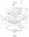
- the flow rate control valves 12a and 12b may be rotary valves 60a and 60b driven by an electric motor, as shown in Fig. 2 .
- an electric motor such as a stepping motor is employed, however an electric motor of any form may be used as long as the rotation angle can be detected.
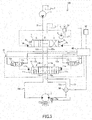
- the flow rate control valves 12a and 12b may be provided with a stroke sensor 12c that detects a stroke of a valve body of the flow rate control valves 12a and 12b. By controlling the stroke of the valve body detected by the stroke sensor 12c while providing feedback, control may be performed with further higher accuracy.
- the fluid pressure control device 100 is configured that the flow rate control valves 12a and 12b are controlled by the controller 40, the flow rate control valves 12a and 12b may be of a variable throttle by manual manipulation. Even with such a configuration, the switching speed of the control valve 11 can be adjusted as appropriate.
- the fluid pressure control device 100 may be configured to control the flow rate control valves 12a and 12b just by the tilt angle detected by the inclination sensor 30, or just by the flow rate detected by the flow rate sensor 50. Furthermore, the flow rate control valves 12a and 12b may be configured by providing just the flow rate control valve 12a being on the forward side.
- the controller 40 may control the flow rate control valves 12a and 12b not just when the vehicle body is in the front side lowered state but also when the vehicle body is in a front side raised state.
- a constant electric current may be applied to the flow rate control valves 12a and 12b to increase or decrease the electric current applied in accordance with the tilt angle of the vehicle body.
- the counterbalance valve 10 includes the flow rate control valves 12a and 12b that variably control the flow rate of the working oil flowing through the pilot passages 13a and 13b. Accordingly, the flow rate of the working oil flown into/discharged from the pilot chambers 11a and 11b of the control valve 11 can be controlled to adjust the switching speed of the control valve 11. This allows for the control valve 11 to adjust a timing of disconnecting the communication between the hydraulic motor 2 and the pump 1 as appropriate, and thus allows for adjusting the braking of the hydraulic motor 2. Therefore, it is possible to adjust the braking distance of the vehicle body as appropriate.
- the flow rate control valves 12a and 12b control the flow of the working oil discharged from the pilot chambers 11a and 11b in accordance with the tilt angle detected by the inclination sensor 30 and the flow rate detected by the flow rate sensor 50.
- the fluid pressure control device 100 includes the position detecting sensor 5a that detects that the directional control valve 3 is in the neutral state, and the inclination sensor 30 that detects the tilt angle of the vehicle body; further, the flow rate control valves 12a and 12b are controlled in accordance with the tilt angle detected by the inclination sensor 30 when the neutral state is detected by the position detecting sensor 5a. Therefore, when the hydraulic motor 2 is to be stopped, the switching speed of the control valve 11 is adjusted in accordance with the tilt angle detected by the inclination sensor 30, to adjust the timing of disconnecting the communication between the hydraulic motor 2 and the pump 1.
- the fluid pressure control device 100 can make the braking force on the hydraulic motor 2 occur in accordance with the tilt angle of the vehicle body by the counterbalance valve 10; thus, the braking of the vehicle body can be performed in an appropriate braking distance even when the vehicle body is tilted with its front side lower.
- the fluid pressure control device 100 includes the flow rate sensor 50 that detects the flow rate of the working oil flowing to the hydraulic motor 2, and the flow rate control valves 12a and 12b are controlled in accordance with the flow rate detected by the flow rate sensor 50. Therefore, when stopping the hydraulic motor 2, the switching speed of the control valve 11 is adjusted in accordance with the flow rate detected by the flow rate sensor 50 to adjust the timing to disconnect the communication between the hydraulic motor 2 and the pump 1. Accordingly, the fluid pressure control device 100 can make a braking force on the hydraulic motor 2 occur in accordance with the speed of the working machine by the counterbalance valve 10; thus, the braking of the vehicle body can be performed at an appropriate braking distance even when the speed of the working machine is fast.
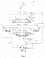
- a fluid pressure control device 200 according to a second embodiment of the present invention is described with reference to Fig. 4 .
- points different from the above first embodiment will be mainly described, and configurations identical to those in the fluid pressure control device 100 of the first embodiment will be given the same reference signs, and description thereof will be omitted.
- the flow rate of the working oil flowing to the hydraulic motor 2 is detected by the flow rate sensor 50.
- the second embodiment differs in the point that the flow rate of the working oil flowing to the hydraulic motor 2 is calculated by a differential pressure gauge 70 and a rotation speed sensor 80. This will be described in detail below.
- the fluid pressure control device 200 includes the differential pressure gauge 70 as a differential pressure detecting unit that detects a differential pressure between a supply side and a discharge side in the hydraulic motor 2, and the rotation speed sensor 80 as a rotational speed detecting unit that detects a rotation speed of the hydraulic motor 2.
- the differential pressure gauge 70 detects pressures of the supply and discharge flow passage 22a and the supply and discharge flow passage 22b, and outputs their difference to the controller 40.
- the rotation speed sensor 80 is provided in the vicinity of a rotational shaft of the hydraulic motor 2, and detects the rotation speed of this rotational shaft and outputs the rotation speed of the hydraulic motor 2 to the controller 40.
- a map is stored in advance which shows a relationship between the differential pressure detected by the differential pressure gauge 70 and a volume efficiency of the hydraulic motor 2.
- the controller 40 calculates the flow rate of the hydraulic motor 2 based on the rotation speed detected by the rotation speed sensor 80, the differential pressure detected by the differential pressure gauge 70, and the above map. By the flow rate calculated as such, the flow rate control valves 12a and 12b are controlled as with the first embodiment.
- a pressure meter may be provided on the supply side and the discharge side of the hydraulic motor 2, and the control may be performed based on a difference between pressures detected by these pressure meters.
- the differential pressure gauge 70 and the rotation speed sensor 80 have small measurement errors as compared to the flow rate sensor 50, and thus can calculate the flow rate with good accuracy. Therefore, the flow rate control valves 12a and 12b can be controlled more accurately. This thus allows for adjusting the braking distance of the vehicle body more suitably in accordance with the rotational speed of the hydraulic motor 2.
- the counterbalance valve 10 includes the valve-side passages 14a and 14b that communicate with the directional control valve 3, the motor-side passages 15a and 15b that communicate with the fluid pressure motor (hydraulic motor 2), the control valve 11 that controls the flow of the working oil between the valve-side passages 14a and 14b and the motor-side passages 15a and 15b when the directional control valve 3 is switched, the pilot chambers 11a and 11b to which pilot pressures for controlling the control valve 11 are guided, the pilot passages 13a and 13b that allow the valve-side passages 14a and 14b to communicate with the pilot chambers 11a and 11b, and the flow rate control valves 12a and 12b that variably control the flow rate of the working oil flowing through the pilot passages 13a and 13b.
- the counterbalance valve 10 includes the flow rate control valves 12a and 12b that variably control the flow rate of the working oil flowing through the pilot passages 13a and 13b;Therefore, by adjusting the flow rate of the working oil flowing into/discharged from the pilot chambers 11a and 11b of the control valve 11, the switching speed of the control valve 11 can be adjusted.
- This allows for adjusting the timing for the control valve 11 to disconnect the communication between the fluid pressure motor (hydraulic motor 2) and the pump 1, and thus can adjust the braking of the fluid pressure motor (hydraulic motor 2). Accordingly, the braking distance of the vehicle body can be suitably adjusted.
- the flow rate control valves 12a and 12b are controlled to increase the flow passage area when the directional control valve 3 is switched from an activation position (forward position A or backward position B) of the fluid pressure motor (hydraulic motor 2) to the stop position (neutral position C) of the fluid pressure motor (hydraulic motor 2).
- the flow passage area increases in the flow rate control valves 12a and 12b when the directional control valve 3 is switched from the activation position of the fluid pressure motor (hydraulic motor 2) (forward position A or backward position B) to the stop position of the fluid pressure motor (hydraulic motor 2).
- This allows for quickening the timing that the control valve 11 disconnects the communication between the fluid pressure motor (hydraulic motor 2) and the pump 1, and can prevent the braking distance of the vehicle body from extending.
- the pilot chambers 11a and 11b are provided on each of end portions of the control valve 11, and the flow rate control valves 12a and 12b are provided in respective pilot passages 13a and 13b that guide the pilot pressure to their respective pilot chambers 11a and 11b.
- the flow rate control valves 12a and 12b are electromagnetic switching valves.
- the flow rate control valves 12a and 12b are electromagnetic switching valves; therefore, the electric current just needs to be switched ON or OFF. This thus allows for simplifying the controlling.
- the flow rate control valves 12a and 12b are rotary valves 60a and 60b driven by an electric motor.
- the flow rate control valves 12a and 12b are electromagnetic proportional control valves.
- minute control can be performed since electric motors and electromagnetic proportional control valves are used.
- the flow rate control valves 12a and 12b further include the stroke sensor 12c that detects the moved amount of the valve body.
- the fluid pressure control device 100 includes the pump 1 that discharges working oil, the fluid pressure motor (hydraulic motor 2) that drives by the working oil discharged from the pump 1, the directional control valve 3 provided in the flow passage connecting the pump 1 with the fluid pressure motor (hydraulic motor 2) and which switches the rotating direction of the fluid pressure motor (hydraulic motor 2), and the counterbalance valve 10 provided between the directional control valve 3 in the flow passage and the fluid pressure motor (hydraulic motor 2).
- the fluid pressure control device 100 further includes the neutral state detecting unit (position detecting sensor 5a) that detects that the directional control valve 3 is in the neutral state, and the inclination detecting unit (inclination sensor 30) that detects the tilt angle of the vehicle body, and the flow rate control valves 12a and 12b are controlled with accordance with the tilt angle detected by the inclination detecting unit (inclination sensor 30) when the neutral position detecting unit (position detecting sensor 5a) detects the neutral state.
- the neutral state detecting unit position detecting sensor 5a
- inclination detecting unit inclination sensor 30
- the flow rate control valves 12a and 12b are controlled in accordance with the tilt angle of the vehicle body when the directional control valve 3 is in the neutral state; thus, the switching speed of the control valve 11 when the fluid pressure motor (hydraulic motor 2) stops can be adjusted in accordance with the tilt angle of the vehicle body. Therefore, the braking of the fluid pressure motor (hydraulic motor 2) can be suitably performed in the state in which the vehicle body is tilted. This allows for suitably adjusting the braking distance of the vehicle body with accordance with the tilted state of the vehicle body.
- the fluid pressure control device 100 further includes the flow rate detecting unit (flow rate sensor 50) that detects the flow rate of the working oil flowing to the fluid pressure motor (hydraulic motor 2), and the flow rate control valves 12a and 12b are controlled in accordance with the detected flow rate detected by the flow rate detecting unit (flow rate sensor 50).
- flow rate sensor 50 the flow rate detecting unit that detects the flow rate of the working oil flowing to the fluid pressure motor (hydraulic motor 2)
- the flow rate control valves 12a and 12b are controlled in accordance with the detected flow rate detected by the flow rate detecting unit (flow rate sensor 50).
- the flow rate control valves 12a and 12b are controlled in accordance with the flow rate detected by the flow rate detecting unit (flow rate sensor 50), and thus the switching speed of the control valve 11 can be adjusted in accordance with the rotational speed of the fluid pressure motor (hydraulic motor 2). This thus allows for suitably adjusting the braking distance of the vehicle body in accordance with the rotational speed of the fluid pressure motor (hydraulic motor 2).
- the fluid pressure control device 100 further includes the differential pressure detecting unit (differential pressure gauge 70) that detects the differential pressure between the supply side and the discharge side of the fluid pressure motor (hydraulic motor 2), and the rotation speed detecting unit (rotation speed sensor 80) that detects the rotation speed of the fluid pressure motor (hydraulic motor 2); and the flow rate control valves 12a and 12b are controlled in accordance with the differential pressure detected by the differential pressure detecting unit (differential pressure gauge 70) and the rotation speed detected by the rotation speed detecting unit (rotation speed sensor 80).
- the differential pressure detecting unit differential pressure gauge 70
- rotation speed detecting unit rotation speed sensor 80
- the working state of the fluid pressure motor (hydraulic motor 2) can be detected based on the differential pressure between the supply side and the discharge side of the fluid pressure motor (hydraulic motor 2) and the rotation speed of the fluid pressure motor (hydraulic motor 2). Since the measurement errors in the differential pressure between the supply side and the discharge side in the fluid pressure motor (hydraulic motor 2) and the rotation speed of the fluid pressure motor (hydraulic motor 2) are small, the flow rate can be calculated with good accuracy. Accordingly, the flow rate control valves 12a and 12b can be controlled more accurately. This thus allows for more suitably adjusting the braking distance of the vehicle body in accordance with the rotational speed of the fluid pressure motor (hydraulic motor 2).
- an oil temperature sensor that detects an oil temperature may be provided in the supply and discharge flow passages 22a and 22b. Since viscosity of the working oil can be calculated from the detected oil temperature, the flow rate control valves 12a and 12b can be controlled with better accuracy by controlling using correction factors (or a map) in accordance with the viscosity.
- the hydraulic motor 2 is described using one for traveling as an example, however the hydraulic motor 2 may be used for revolving.
- a sensor that detects a position of the valve body of the directional control valve 3 may be provided.
- the neutral state of the directional control valve 3 may be detected by detecting a pressure of the pilot chambers 3a and 3b or the pilot flow passage communicating with the pilot chambers 3a and 3b.
Landscapes
- Engineering & Computer Science (AREA)
- General Engineering & Computer Science (AREA)
- Physics & Mathematics (AREA)
- Fluid Mechanics (AREA)
- Mining & Mineral Resources (AREA)
- Civil Engineering (AREA)
- Structural Engineering (AREA)
- Mechanical Engineering (AREA)
- Chemical & Material Sciences (AREA)
- Analytical Chemistry (AREA)
- Fluid-Pressure Circuits (AREA)
- Operation Control Of Excavators (AREA)
Abstract
A counterbalance valve (10) includes: a valve-side passage (14a,14b) communicating with the directional control valve (3); a motor-side passage (15a,15b) communicating with the fluid pressure motor (2); a control valve (11) configured to control flowing of working fluid between the valve-side passage (14a,14b) and the motor-side passage (15a,15b) when the directional control valve (3) is switched; a pilot chamber (11a,11b) to which pilot pressure for controlling the control valve (11) is guided; a pilot passage (13a,13b) communicating the valve-side passage (14a,14b) with the pilot chamber (11a,11b); and a flow rate control valve (12a,12b) configured to variably control a flow rate of working fluid flowing through the pilot passage (13a,13b).
Description
- The present invention relates to a counterbalance valve and a fluid pressure control device including a counterbalance valve.
-
JP06-147201A JP06-147201A JP06-147201A - Generally, the orifice diameter is set on the basis that the construction machine will travel on flat surface. However, by setting the orifice diameter on the basis of traveling on flat surface, the distance until the construction machine stops would extend when attempting to stop while traveling on a downslope. On the contrary, if the orifice diameter is set on the basis of traveling on the downslope, the construction machine would suddenly stop when attempting to stop while traveling on flat surface.
- An object of the present invention is to provide a counterbalance valve that can appropriately adjust a braking distance of a vehicle body, and a fluid pressure control device comprising this counterbalance valve.
- According to one aspect of the present invention, a counterbalance valve includes: a valve-side passage communicating with the directional control valve; a motor-side passage communicating with the fluid pressure motor; a control valve configured to control flowing of working fluid between the valve-side passage and the motor-side passage when the directional control valve is switched; a pilot chamber to which pilot pressure for controlling the control valve is guided; a pilot passage communicating the valve-side passage with the pilot chamber; and a flow rate control valve configured to variably control a flow rate of working fluid flowing through the pilot passage.
-
- [
Fig. 1] Fig. 1 is a hydraulic circuit diagram of a hydraulic control device according to a first embodiment of the present invention. - [
Fig. 2] Fig. 2 is a hydraulic circuit diagram showing a modification of the hydraulic control device of the first embodiment of the present invention. - [
Fig. 3] Fig. 3 is a hydraulic circuit diagram showing a modification of the hydraulic control device of the first embodiment of the present invention. - [
Fig. 4] Fig. 4 is a hydraulic circuit diagram showing a hydraulic control device according to a second embodiment of the present invention. - Described below with reference to the drawings are a
counterbalance valve 10 and a fluidpressure control device 100 including thecounterbalance valve 10, according to a first embodiment of the present invention.Fig. 1 is a hydraulic circuit diagram showing thecounterbalance valve 10 and the fluidpressure control device 100 including thecounterbalance valve 10, in the first embodiment. - The fluid
pressure control device 100 is mounted in a vehicle body of a working machine that is driven by fluid pressure, such as a power shovel or a wheel loader. In the fluidpressure control device 100, although working oil is used as the working fluid, other fluids such as working water may be used as the working fluid. - As shown in
Fig. 1 , the fluidpressure control device 100 includes apump 1 that discharges working oil, ahydraulic motor 2 as a fluid pressure motor driven by the working oil discharged from thepump 1, adirectional control valve 3 provided in a flow passage connecting thepump 1 with thehydraulic motor 2 and which switches a rotating direction of thehydraulic motor 2, asupply flow passage 21 connecting thepump 1 with thedirectional control valve 3, supply anddischarge flow passages hydraulic motor 2 with thedirectional control valve 3, and aremote control valve 5 that controls pilot pressure of thedirectional control valve 3. - The
pump 1 is driven by power of an engine not shown, and discharges working oil to thesupply flow passage 21. Thepump 1 is a swash plate axial piston pump. Although thepump 1 is shown as a fixed displacement type inFig. 1 , it is not limited to this and may be a variable displacement type. - The
hydraulic motor 2 is a swash plate axial piston motor with a fixed displacement, and is used as a hydraulic motor for traveling. Thehydraulic motor 2 is rotatably driven upon receiving supply of the working oil discharged from thepump 1. Thehydraulic motor 2 switches between forward rotation and reverse rotation caused by thedirectional control valve 3. With the forward rotation of thehydraulic motor 2, the working machine moves forward, and with the reverse rotation of thehydraulic motor 2, the working machine moves backward. Thehydraulic motor 2 is not limited to the swash plate axial piston motor of the fixed displacement, and may be a swash plate axial piston motor of a variable displacement. - The
hydraulic motor 2 is provided with a negativetype parking brake 2a that applies braking force to thehydraulic motor 2 when stopping. Theparking brake 2a is connected to acounterbalance valve 10 described later, via aflow passage 23. Theparking brake 2a allows thehydraulic motor 2 to rotate upon releasing the brake when the pressure of theflow passage 23 exceeds a predetermined pressure (brake release pressure). - The
directional control valve 3 includes a forward position A that guides the working oil discharged from thepump 1 into thesupply flow passage 21 to thehydraulic motor 2 through the supply anddischarge flow passage 22a, a backward position B that guides the working oil discharged from thepump 1 into thesupply flow passage 21 to thehydraulic motor 2 through the supply anddischarge flow passage 22b, and a neutral position C that allows thepump 1 and thehydraulic motor 2 to communicate with a tank T. Thedirectional control valve 3 is switched due to working oil (pilot pressure) supplied from a pilot pump 4 topilot chambers remote control valve 5 in association with an operator of the working machine manipulating theremote control valve 5. More specifically, when theremote control valve 5 is manipulated to one side and pilot pressure is supplied to thepilot chamber 3a, thedirectional control valve 3 switches to the forward position A, and when theremote control valve 5 is manipulated to the other side and the pilot pressure is supplied to thepilot chamber 3b, thedirectional control valve 3 switches to the backward position B. When theremote control valve 5 is in a neutral position, that is, when no pilot pressure is acting on either of thepilot chambers directional control valve 3 becomes in the neutral position C due to an energizing force ofsprings 3c provided on both sides of thedirectional control valve 3. The pilot pressure supplied to thepilot chambers remote control valve 5. - The
remote control valve 5 includes aposition detecting sensor 5a that detects a neutral state of theremote control valve 5. Theposition detecting sensor 5a outputs a detection signal to acontroller 40 when the operation lever of theremote control valve 5 is in the neutral position. When theremote control valve 5 is in the neutral state, thedirectional control valve 3 is also in the neutral state. Namely, the neutral state of thedirectional control valve 3 can be detected by theposition detecting sensor 5a. Theposition detecting sensor 5a is equivalent to a neutral state detecting unit adapted to detect that thedirectional control valve 3 is in the neutral state. - The fluid
pressure control device 100 further includes thecounterbalance valve 10 provided between thedirectional control valve 3 and thehydraulic motor 2. Thecounterbalance valve 10 is provided in the supply anddischarge flow passages - The
counterbalance valve 10 includes valve-side passages directional control valve 3 through the supply anddischarge flow passages side passages hydraulic motor 2 through the supply anddischarge flow passages control valve 11 that controls the flow of the working oil between the valve-side passages side passages directional control valve 3 is switched,pilot chambers control valve 11 is guided,pilot passages side passages pilot chambers rate control valves pilot passages pilot passages - The
pilot chambers control valve 11. Thepilot passages side passages pilot chambers - The
control valve 11 includes a working position D that allows the valve-side passage 14a to communicate with the motor-side passage 15a and theflow passage 23 and allows the valve-side passage 14b to communicate with the motor-side passage 15b, a working position E that allows the valve-side passage 14a to communicate with the motor-side passage 15a and allows the valve-side passage 14b to communicate with the motor-side passage 15b and theflow passage 23, and a neutral position F that disconnects the communication between the valve-side passage side passage - When the
directional control valve 3 is switched to the forward position A, thecontrol valve 11 is switched to the working position D by the working oil discharged from thepump 1 being guided to thepilot chamber 11a through the supply anddischarge flow passage 22a, the valve-side passage 14a and thepilot passage 13a. Moreover, when thedirectional control valve 3 is switched to the backward position B, thecontrol valve 11 is switched to the working position E by the working oil discharged from thepump 1 being guided to thepilot chamber 11b through the supply anddischarge flow passage 22b, the valve-side passage 14b and thepilot passage 13b. Furthermore, when thedirectional control valve 3 is switched to the neutral position C, thecontrol valve 11 is switched to the neutral position F by the working oil within thepilot chambers discharge flow passages pilot passages side passages spring 11c provided on both sides. - The flow
rate control valves directional control valve 3 is in the neutral state, the flowrate control valves pilot passages controller 40. Namely, the flowrate control valves rate control valves controller 40, and is controlled to have the flow passage area (throttle) increase as the electric current applied from thecontroller 40 increases. The flowrate control valves pilot chambers control valve 11, by controlling the flow rate of the working oil flowing through thepilot passages - The fluid
pressure control device 100 further includes aninclination sensor 30 as an inclination detecting unit to detect a tilt angle of a vehicle body of the working machine, and aflow rate sensor 50 as a flow rate detecting unit to detect the flow rate of the working oil flowing to thehydraulic motor 2. - The
inclination sensor 30 detects the tilt angle in the forward-backward direction towards a horizontal plane of the vehicle body of the working machine, and outputs the detected tilt angle to thecontroller 40. - The
flow rate sensor 50 is provided in the supply anddischarge flow passage 22a, detects the flow rate of the working oil flowing through the supply anddischarge flow passage 22a and outputs the detected flow rate to thecontroller 40. Theflow rate sensor 50 may be provided in the supply anddischarge flow passage 22b. - Operations of the
counterbalance valve 10 and the fluidpressure control device 100 configured as above will be described. - First described is a case of moving the working machine forwards.
- When the operator manipulates the
remote control valve 5 towards one side, the working oil discharged from the pilot pump 4 is supplied to thepilot chamber 3a through theremote control valve 5. At this time, thepilot chamber 3a is supplied with a pilot pressure in accordance with the manipulated amount of theremote control valve 5. This causes thedirectional control valve 3 to switch to the forward position A, and the working oil discharged from thepump 1 flows from thesupply flow passage 21 into the valve-side passage 14a of thecounterbalance valve 10 through the supply anddischarge flow passage 22a. - A part of the working oil flowing into the valve-
side passage 14a of thecounterbalance valve 10 flows into thepilot chamber 11a through thepilot passage 13a. This causes thecontrol valve 11 to switch to the working position D. At this time, thedirectional control valve 3 is not in the neutral state, and thus no electric current from thecontroller 40 is applied to the flowrate control valve 12a. Accordingly, the flow passage area of the flowrate control valve 12a is at its minimum. Therefore, since the flow is limited by the flowrate control valve 12a, the working oil flowing through thepilot passage 13a flows gently into thepilot chamber 11a. This causes thecontrol valve 11 to gradually switch to the working position D. - When the
control valve 11 switches to the working position D, the working oil discharged from thepump 1 is supplied to thehydraulic motor 2 through thesupply flow passage 21, thedirectional control valve 3, the supply anddischarge flow passage 22a, the valve-side passage 14a, thecontrol valve 11, the motor-side passage 15a, and the supply anddischarge flow passage 22a. Simultaneously to this, the working oil discharged from thepump 1 is supplied to theparking brake 2a via thecontrol valve 11 through theflow passage 23, thereby releasing theparking brake 2a. This causes thehydraulic motor 2 to rotate forwardly, and the working machine moves forward. - The flow rate of the working oil flowing through the supply and
discharge flow passage 22a is detected by theflow rate sensor 50, and the detected flow rate is outputted to thecontroller 40. The working oil discharged from thehydraulic motor 2 is returned to the tank T through the supply anddischarge flow passage 22b, the motor-side passage 15b, thecontrol valve 11, the valve-side passage 14b, the supply anddischarge flow passage 22b, and thedirectional control valve 3. - Next describes a case of the working machine stopping from the moving forward state.
- When the operator returns the
remote control valve 5 to the neutral position, the working oil of thepilot chamber 3a is discharged to the tank T through theremote control valve 5. This causes thedirectional control valve 3 to return to the neutral position C due to the energizing force of thesprings 3c provided in thedirectional control valve 3. - When the
directional control valve 3 returns to the neutral position C, the valve-side passage 14a communicates with the tank T through the supply anddischarge flow passage 22a and thedirectional control valve 3. This causes the working oil within thepilot chamber 11a to be discharged to the tank T through thepilot passage 13a, the valve-side passage 14a, the supply anddischarge flow passage 22a, and thedirectional control valve 3. - When the
remote control valve 5 is returned to the neutral position, theposition detecting sensor 5a provided in theremote control valve 5 detects that the operation lever of theremote control valve 5 is in the neutral state, and outputs a detection signal to thecontroller 40. When the detection signal is received from theposition detecting sensor 5a, thecontroller 40 applies an electric current in accordance with the tilt angle detected by theinclination sensor 30, to the flowrate control valve 12a. More specifically, thecontroller 40 applies no electric current to the flowrate control valve 12a when the working machine is in a horizontal state, and when the working machine is in a state tilted with the front side lower, a larger electric current is applied to the flowrate control valve 12a with a larger tilt angle of the vehicle body. Namely, when the vehicle body is tilted with the front side lower, a large electric current is applied to the flowrate control valve 12a, and the flow passage area of the flowrate control valve 12a increases. This causes the resistance due to the throttle of the flowrate control valve 12a against the flow of the working oil discharged from thepilot chamber 11a to decrease, and thus the switching speed of thecontrol valve 11 increases. Accordingly, when the vehicle body is tilted with the front side lower, thecontrol valve 11 switches to the neutral position F from the working position D quicker than the case in which the vehicle body is in the horizontal state. Therefore, when the vehicle body is tilted with the front side lower, namely, when the working machine is traveling forward on a downslope, the communication between the valve-side passage 14a and the motor-side passage 15a is disconnected quicker than when the vehicle body is in the horizontal state, and the braking force to thehydraulic motor 2 occurs quicker. As such, the fluidpressure control device 100 can make the braking force to thehydraulic motor 2 occur earlier when the working machine is traveling forward on the downslope, and thus the braking distance at the time of the working machine stopping can be made shorter. - Moreover, the
controller 40 receives the flow rate of the supply anddischarge flow passage 22a detected by theflow rate sensor 50. When the detection signal is received from theposition detecting sensor 5a, thecontroller 40 applies an electric current to the flowrate control valve 12a in accordance with the flow rate detected by theflow rate sensor 50. More specifically, thecontroller 40 applies a larger electric current to the flowrate control valve 12a with a greater flow rate. The flow rate detected by theflow rate sensor 50 is equal to the flow rate of the working oil supplied to thehydraulic motor 2, and thus with a greater flow rate detected at theflow rate sensor 50, a rotational speed of thehydraulic motor 2 will become faster. Namely, with a faster rotational speed of thehydraulic motor 2, a greater electric current is applied to the flowrate control valve 12a and the flow passage area increases. Accordingly, since the working oil of thepilot chamber 11a is discharged without receiving any effect due to the throttle of the flowrate control valve 12a, the switching speed of thecontrol valve 11 increases. This makes the switching speed of thecontrol valve 11 faster when the rotational speed of thehydraulic motor 2 is faster, and thus thecontrol valve 11 switches quickly from the working position D to the neutral position F. Accordingly, when the rotational speed of thehydraulic motor 2 is fast, namely, in a case in which the speed of the working machine is fast, the switching speed of thecontrol valve 11 will increase, and thus the communication between the valve-side passage 14a and the motor-side passage 15a will be disconnected quicker than the case in which the rotational speed of thehydraulic motor 2 is slow (when the speed of the working machine is slow), and the braking force occurs quicker to thehydraulic motor 2. As such, the fluidpressure control device 100 can cause the braking force to thehydraulic motor 2 to occur quicker when the speed of the working machine is fast, and thus the braking distance of the working machine can be made short. - Next describes a case of moving the working machine backwards.
- When the operator manipulates the
remote control valve 5 towards the other side, the working oil discharged from the pilot pump 4 is supplied to thepilot chamber 3b through theremote control valve 5. At this time, thepilot chamber 3b is supplied with a pilot pressure in accordance with the manipulated amount of theremote control valve 5. This makes thedirectional control valve 3 switch to the backward position B, and the working oil discharged from thepump 1 flows from thesupply flow passage 21 into the valve-side passage 14b of thecounterbalance valve 10 through the supply anddischarge flow passage 22b. - A part of the working oil flown into the valve-
side passage 14b of thecounterbalance valve 10 flows into thepilot chamber 11b through thepilot passage 13b. This causes thecontrol valve 11 to switch to the working position E. At this time, thedirectional control valve 3 is not in the neutral state, and thus no electric current is applied from thecontroller 40 to the flowrate control valve 12b. Therefore, the flow passage area of the flowrate control valve 12b is in its minimum. Therefore, the working oil flowing through thepilot passage 13b is limited in the flow by the flowrate control valve 12b, and thus the working oil flows into thepilot chamber 11b gradually. This causes thecontrol valve 11 to switch to the working position E gradually. - When the
control valve 11 switches to the working position E, the working oil discharged from thepump 1 is supplied to thehydraulic motor 2 through thesupply flow passage 21, thedirectional control valve 3, the supply anddischarge flow passage 22b, the valve-side passage 14b, thecontrol valve 11, the motor-side passage 15b, and the supply anddischarge flow passage 22b. Simultaneously to this, the working oil discharged from thepump 1 is supplied to theparking brake 2a from thecontrol valve 11 through theflow passage 23, and theparking brake 2a is released. This causes thehydraulic motor 2 to rotate backwards, and the working machine moves backwards. - The working oil discharged from the
hydraulic motor 2 is returned to the tank T through the supply anddischarge flow passage 22a, the motor-side passage 15a, thecontrol valve 11, the valve-side passage 14a, the supply anddischarge flow passage 22a, and thedirectional control valve 3. At this time, the flow rate of the working oil flowing through the supply anddischarge flow passage 22a is detected by theflow rate sensor 50, and the detected flow rate is outputted to thecontroller 40. - Next described is a case of the working machine stopping from a state moving backward.
- When the operator returns the
remote control valve 5 to the neutral position, the working oil of thepilot chamber 3b is discharged to the tank T through theremote control valve 5. This causes thedirectional control valve 3 to return to the neutral position C due to the energizing force of thespring 3c provided in thedirectional control valve 3. - When the
directional control valve 3 is returned to the neutral position C, the valve-side passage 14b communicates with the tank T through the supply anddischarge flow passage 22b and thedirectional control valve 3. This causes the working oil within thepilot chamber 11b to be discharged to the tank T through thepilot passage 13b, the valve-side passage 14b, the supply anddischarge flow passage 22b, and thedirectional control valve 3. - When the
remote control valve 5 is returned to the neutral position, theposition detecting sensor 5a provided in theremote control valve 5 detects that the operation lever of theremote control valve 5 is in the neutral position, and outputs a detection signal to thecontroller 40. When the detection signal is received from theposition detecting sensor 5a, thecontroller 40 applies an electric current in accordance with a tilt angle detected by theinclination sensor 30, to the flowrate control valve 12b. More specifically, when the working machine is in the horizontal state, thecontroller 40 applies no electric current to the flowrate control valve 12b, and when the working machine is in a tilted state with its rear side lower, thecontroller 40 applies a greater electric current to the flowrate control valve 12b with a larger tilt angle of the vehicle body. Namely, when the vehicle body is tilted with its rear side lower, a greater electric current is applied to the flowrate control valve 12b, and the flow passage area increases. This reduces the resistance caused by the throttle of the flowrate control valve 12b against the flow of the working oil discharged from thepilot chamber 11b, and thus the switching speed of thecontrol valve 11 increases. Accordingly, when the vehicle body is tilted with its rear side lower, thecontrol valve 11 switches from the working position E to the neutral position F quicker than the case in which the vehicle body is in the horizontal state. Therefore, when the vehicle is tilted with its rear side lower, namely, when the working machine is travelling backward on a downslope, the communication between the valve-side passage 14b and the motor-side passage 15b is disconnected quicker than the case in which the vehicle body is in the horizontal state, and the braking force on thehydraulic motor 2 occurs earlier. As such, the fluidpressure control device 100 can cause the braking force on thehydraulic motor 2 to occur earlier, and thus can shorten the braking distance at the time of stopping the working machine. - Moreover, the
controller 40 receives the flow rate of the supply anddischarge flow passage 22a that is detected by theflow rate sensor 50. When the detection signal is received from theposition detecting sensor 5a, thecontroller 40 applies an electric current in accordance with the flow rate detected by theflow rate sensor 50 to the flowrate control valve 12b. More specifically, thecontroller 40 applies a greater electric current to the flowrate control valve 12b with a greater flow rate. The flow rate detected by theflow rate sensor 50 is equal to the flow rate of the working oil supplied to thehydraulic motor 2, and thus when the flow rate detected at theflow rate sensor 50 is great, the rotational speed of thehydraulic motor 2 will be fast. Namely, the faster the rotational speed of thehydraulic motor 2 is, the larger the applied electric current is to the flowrate control valve 12b, and the flow passage area increases. Accordingly, since the working oil of thepilot chamber 11b is discharged without receiving any effect by the throttle of the flowrate control valve 12b, the switching speed of thecontrol valve 11 increases. This causes the switching speed of thecontrol valve 11 to increase when the rotational speed of thehydraulic motor 2 is fast, and thus thecontrol valve 11 switches from the working position E to the neutral position F quickly. Accordingly, when the rotational speed of thehydraulic motor 2 is fast, namely, when the speed of the working machine is fast, the switching speed of thecontrol valve 11 increases; thus, the communication between the valve-side passage 14b and the motor-side passage 15b is disconnected earlier than when the rotational speed of thehydraulic motor 2 is slow (when the speed of the working machine is slow), and the braking force in thehydraulic motor 2 occurs earlier. As such, the fluidpressure control device 100 can cause the braking force on thehydraulic motor 2 to occur earlier when the speed of the working machine is fast, and thus can shorten the braking distance of the working machine. - Although the flow
rate control valves inclination sensor 30 and the flow rate detected by theflow rate sensor 50, and make the position of the electromagnetic switching valve to switch their positions when the threshold value is exceeded. This requires just the ON/OFF controlling of the positions of the flowrate control valves controller 40. - Moreover, the flow
rate control valves rotary valves Fig. 2 . In this case, by detecting a rotation angle with for example a rotation angle sensor and performing feedback control, a control can be performed with high accuracy. An electric motor such as a stepping motor is employed, however an electric motor of any form may be used as long as the rotation angle can be detected. Furthermore, as shown inFig. 3 , the flowrate control valves stroke sensor 12c that detects a stroke of a valve body of the flowrate control valves stroke sensor 12c while providing feedback, control may be performed with further higher accuracy. - Although the fluid
pressure control device 100 is configured that the flowrate control valves controller 40, the flowrate control valves control valve 11 can be adjusted as appropriate. - Moreover, the fluid
pressure control device 100 may be configured to control the flowrate control valves inclination sensor 30, or just by the flow rate detected by theflow rate sensor 50. Furthermore, the flowrate control valves rate control valve 12a being on the forward side. - Moreover, the
controller 40 may control the flowrate control valves directional control valve 3 is in the neutral state, a constant electric current may be applied to the flowrate control valves - According to the above first embodiment, the following effects are exerted.
- The
counterbalance valve 10 includes the flowrate control valves pilot passages pilot chambers control valve 11 can be controlled to adjust the switching speed of thecontrol valve 11. This allows for thecontrol valve 11 to adjust a timing of disconnecting the communication between thehydraulic motor 2 and thepump 1 as appropriate, and thus allows for adjusting the braking of thehydraulic motor 2. Therefore, it is possible to adjust the braking distance of the vehicle body as appropriate. - Furthermore, when the
directional control valve 3 is returned from the forward position A or backward position B that cause thehydraulic motor 2 to actuate, to the neutral position C that causes thehydraulic motor 2 to stop, the flowrate control valves pilot chambers inclination sensor 30 and the flow rate detected by theflow rate sensor 50. - When the vehicle body is tilted with its front side lower, the braking distance extends due to self-weight of the working machine. However, the fluid
pressure control device 100 includes theposition detecting sensor 5a that detects that thedirectional control valve 3 is in the neutral state, and theinclination sensor 30 that detects the tilt angle of the vehicle body; further, the flowrate control valves inclination sensor 30 when the neutral state is detected by theposition detecting sensor 5a. Therefore, when thehydraulic motor 2 is to be stopped, the switching speed of thecontrol valve 11 is adjusted in accordance with the tilt angle detected by theinclination sensor 30, to adjust the timing of disconnecting the communication between thehydraulic motor 2 and thepump 1. Accordingly, the fluidpressure control device 100 can make the braking force on thehydraulic motor 2 occur in accordance with the tilt angle of the vehicle body by thecounterbalance valve 10; thus, the braking of the vehicle body can be performed in an appropriate braking distance even when the vehicle body is tilted with its front side lower. - Furthermore, the fluid
pressure control device 100 includes theflow rate sensor 50 that detects the flow rate of the working oil flowing to thehydraulic motor 2, and the flowrate control valves flow rate sensor 50. Therefore, when stopping thehydraulic motor 2, the switching speed of thecontrol valve 11 is adjusted in accordance with the flow rate detected by theflow rate sensor 50 to adjust the timing to disconnect the communication between thehydraulic motor 2 and thepump 1. Accordingly, the fluidpressure control device 100 can make a braking force on thehydraulic motor 2 occur in accordance with the speed of the working machine by thecounterbalance valve 10; thus, the braking of the vehicle body can be performed at an appropriate braking distance even when the speed of the working machine is fast. - A fluid
pressure control device 200 according to a second embodiment of the present invention is described with reference toFig. 4 . Hereinafter, points different from the above first embodiment will be mainly described, and configurations identical to those in the fluidpressure control device 100 of the first embodiment will be given the same reference signs, and description thereof will be omitted. - In the first embodiment, the flow rate of the working oil flowing to the
hydraulic motor 2 is detected by theflow rate sensor 50. The second embodiment differs in the point that the flow rate of the working oil flowing to thehydraulic motor 2 is calculated by adifferential pressure gauge 70 and arotation speed sensor 80. This will be described in detail below. - The fluid
pressure control device 200 includes thedifferential pressure gauge 70 as a differential pressure detecting unit that detects a differential pressure between a supply side and a discharge side in thehydraulic motor 2, and therotation speed sensor 80 as a rotational speed detecting unit that detects a rotation speed of thehydraulic motor 2. Thedifferential pressure gauge 70 detects pressures of the supply anddischarge flow passage 22a and the supply anddischarge flow passage 22b, and outputs their difference to thecontroller 40. Therotation speed sensor 80 is provided in the vicinity of a rotational shaft of thehydraulic motor 2, and detects the rotation speed of this rotational shaft and outputs the rotation speed of thehydraulic motor 2 to thecontroller 40. - In the
controller 40, a map is stored in advance which shows a relationship between the differential pressure detected by thedifferential pressure gauge 70 and a volume efficiency of thehydraulic motor 2. The flow rate of the working oil flowing through thehydraulic motor 2 can be calculated by a formula of "Flow rate = Displacement volume × Rotation speed × Volume efficiency". Thecontroller 40 calculates the flow rate of thehydraulic motor 2 based on the rotation speed detected by therotation speed sensor 80, the differential pressure detected by thedifferential pressure gauge 70, and the above map. By the flow rate calculated as such, the flowrate control valves differential pressure gauge 70, a pressure meter may be provided on the supply side and the discharge side of thehydraulic motor 2, and the control may be performed based on a difference between pressures detected by these pressure meters. - According to the above second embodiment, the following effects are exerted in addition to the effects of the first embodiment.
- The
differential pressure gauge 70 and therotation speed sensor 80 have small measurement errors as compared to theflow rate sensor 50, and thus can calculate the flow rate with good accuracy. Therefore, the flowrate control valves hydraulic motor 2. - Description is made collectively for the configuration, functions, and effects of the embodiment of the present invention configured as described above.
- The
counterbalance valve 10 includes the valve-side passages directional control valve 3, the motor-side passages control valve 11 that controls the flow of the working oil between the valve-side passages side passages directional control valve 3 is switched, thepilot chambers control valve 11 are guided, thepilot passages side passages pilot chambers rate control valves pilot passages - In this configuration, the
counterbalance valve 10 includes the flowrate control valves pilot passages pilot chambers control valve 11, the switching speed of thecontrol valve 11 can be adjusted. This allows for adjusting the timing for thecontrol valve 11 to disconnect the communication between the fluid pressure motor (hydraulic motor 2) and thepump 1, and thus can adjust the braking of the fluid pressure motor (hydraulic motor 2). Accordingly, the braking distance of the vehicle body can be suitably adjusted. - Moreover, in the
counterbalance valve 10, the flowrate control valves directional control valve 3 is switched from an activation position (forward position A or backward position B) of the fluid pressure motor (hydraulic motor 2) to the stop position (neutral position C) of the fluid pressure motor (hydraulic motor 2). - In this configuration, the flow passage area increases in the flow
rate control valves directional control valve 3 is switched from the activation position of the fluid pressure motor (hydraulic motor 2) (forward position A or backward position B) to the stop position of the fluid pressure motor (hydraulic motor 2). This allows for quickening the timing that thecontrol valve 11 disconnects the communication between the fluid pressure motor (hydraulic motor 2) and thepump 1, and can prevent the braking distance of the vehicle body from extending. - Moreover, in the
counterbalance valve 10, thepilot chambers control valve 11, and the flowrate control valves respective pilot passages respective pilot chambers - In this configuration, whichever direction the fluid pressure motor (hydraulic motor 2) activates, the switching speed of the
control valve 11 can be adjusted; therefore, whichever direction the vehicle body travels, the braking distance of the vehicle body can be suitably adjusted. - Moreover, in the
counterbalance valve 10, the flowrate control valves - In this configuration, the flow
rate control valves - Moreover, in the
counterbalance valve 10, the flowrate control valves rotary valves - Moreover, in the
counterbalance valve 10, the flowrate control valves - In these configurations, minute control can be performed since electric motors and electromagnetic proportional control valves are used.
- Moreover, in the
counterbalance valve 10, the flowrate control valves stroke sensor 12c that detects the moved amount of the valve body. - In this configuration, by providing feedback of the moved amount of the valve body detected by the
stroke sensor 12c, a more accurate control can be performed. - The fluid
pressure control device 100 includes thepump 1 that discharges working oil, the fluid pressure motor (hydraulic motor 2) that drives by the working oil discharged from thepump 1, thedirectional control valve 3 provided in the flow passage connecting thepump 1 with the fluid pressure motor (hydraulic motor 2) and which switches the rotating direction of the fluid pressure motor (hydraulic motor 2), and thecounterbalance valve 10 provided between thedirectional control valve 3 in the flow passage and the fluid pressure motor (hydraulic motor 2). - Moreover, the fluid
pressure control device 100 further includes the neutral state detecting unit (position detecting sensor 5a) that detects that thedirectional control valve 3 is in the neutral state, and the inclination detecting unit (inclination sensor 30) that detects the tilt angle of the vehicle body, and the flowrate control valves position detecting sensor 5a) detects the neutral state. - In this configuration, the flow
rate control valves directional control valve 3 is in the neutral state; thus, the switching speed of thecontrol valve 11 when the fluid pressure motor (hydraulic motor 2) stops can be adjusted in accordance with the tilt angle of the vehicle body. Therefore, the braking of the fluid pressure motor (hydraulic motor 2) can be suitably performed in the state in which the vehicle body is tilted. This allows for suitably adjusting the braking distance of the vehicle body with accordance with the tilted state of the vehicle body. - Moreover, the fluid
pressure control device 100 further includes the flow rate detecting unit (flow rate sensor 50) that detects the flow rate of the working oil flowing to the fluid pressure motor (hydraulic motor 2), and the flowrate control valves - In this configuration, the flow
rate control valves control valve 11 can be adjusted in accordance with the rotational speed of the fluid pressure motor (hydraulic motor 2). This thus allows for suitably adjusting the braking distance of the vehicle body in accordance with the rotational speed of the fluid pressure motor (hydraulic motor 2). - Moreover, the fluid
pressure control device 100 further includes the differential pressure detecting unit (differential pressure gauge 70) that detects the differential pressure between the supply side and the discharge side of the fluid pressure motor (hydraulic motor 2), and the rotation speed detecting unit (rotation speed sensor 80) that detects the rotation speed of the fluid pressure motor (hydraulic motor 2); and the flowrate control valves - According to this configuration, the working state of the fluid pressure motor (hydraulic motor 2) can be detected based on the differential pressure between the supply side and the discharge side of the fluid pressure motor (hydraulic motor 2) and the rotation speed of the fluid pressure motor (hydraulic motor 2). Since the measurement errors in the differential pressure between the supply side and the discharge side in the fluid pressure motor (hydraulic motor 2) and the rotation speed of the fluid pressure motor (hydraulic motor 2) are small, the flow rate can be calculated with good accuracy. Accordingly, the flow
rate control valves - Embodiments of this invention were described above, but the above embodiments are merely examples of applications of this invention, and the technical scope of this invention is not limited to the specific constitutions of the above embodiments.
- For example, in each of the above embodiments, an oil temperature sensor that detects an oil temperature may be provided in the supply and
discharge flow passages rate control valves - Moreover, in each of the above embodiments, the
hydraulic motor 2 is described using one for traveling as an example, however thehydraulic motor 2 may be used for revolving. - As a configuration for detecting the neutral state of the
directional control valve 3, a sensor that detects a position of the valve body of thedirectional control valve 3 may be provided. Alternatively, the neutral state of thedirectional control valve 3 may be detected by detecting a pressure of thepilot chambers pilot chambers - This application claims priority based on Japanese Patent Application No.
2015-227811
Claims (11)
- A counterbalance valve provided in a flow passage connecting a fluid pressure motor with a directional control valve, the fluid pressure motor being provided on a vehicle body and being configured to be driven by working fluid discharged from a pump, the directional control valve being configured to switch a rotating direction of the fluid pressure motor, the counterbalance valve comprising:a valve-side passage communicating with the directional control valve;a motor-side passage communicating with the fluid pressure motor;a control valve configured to control flowing of working fluid between the valve-side passage and the motor-side passage when the directional control valve is switched;a pilot chamber to which pilot pressure for controlling the control valve is guided;a pilot passage communicating the valve-side passage with the pilot chamber; anda flow rate control valve configured to variably control a flow rate of working fluid flowing through the pilot passage.
- The counterbalance valve according to claim 1, wherein
the flow rate control valve is controlled to increase a flow passage area when the directional control valve is switched from an activation position of the fluid pressure motor to a stop position of the fluid pressure motor. - The counterbalance valve according to claim 1 or 2, wherein
the pilot chamber is provided on each of end portions of the control valve, and
the flow rate control valve is provided in the pilot passage, the pilot passage being configured to guide pilot pressure to the pilot chamber. - The counterbalance valve according to claim 1 or 2, wherein
the flow rate control valve is an electromagnetic switching valve. - The counterbalance valve according to claim 1 or 2, wherein
the flow rate control valve is a rotary valve driven by an electric motor. - The counterbalance valve according to claim 1 or 2, wherein
the flow rate control valve is an electromagnetic proportional control valve. - The counterbalance valve according to claim 6, wherein
the flow rate control valve has a stroke sensor configured to detect a moved amount of a valve body. - A fluid pressure control device for controlling the fluid pressure motor, the fluid pressure control device comprising:the pump configured to discharge working fluid;the fluid pressure motor configured to be driven by working fluid discharged from the pump;the directional control valve provided in a flow passage connecting the pump with the fluid pressure motor, the directional control valve being configured to switch a rotating direction of the fluid pressure motor; andthe counterbalance valve according to claim 1 or 2, provided between the directional control valve in the flow passage and the fluid pressure motor.
- The fluid pressure control device according to claim 8, further comprising:a neutral state detecting unit configured to detect that the directional control valve is in a neutral state; andan inclination detecting unit configured to detect a tilt angle of the vehicle body, whereinthe flow rate control valve is controlled in accordance with a tilt angle detected by the inclination detecting unit when the neutral position is detected by the neutral position detecting unit.
- The fluid pressure control device according to claim 8, further comprising:a flow rate detecting unit configured to detect a flow rate of working fluid flowing to the fluid pressure motor, whereinthe flow rate control valve is controlled in accordance with the flow rate detected by the flow rate detecting unit.
- The fluid pressure control device according to claim 9, further comprising:a differential pressure detecting unit configured to detect a differential pressure between a supply side and a discharge side in the fluid pressure motor; anda rotation speed detecting unit configured to detect a rotation speed of the fluid pressure motor, whereinthe flow rate control valve is controlled in accordance with the differential pressure detected by the differential pressure detecting unit and the rotation speed detected by the rotation speed detecting unit.
Applications Claiming Priority (2)
| Application Number | Priority Date | Filing Date | Title |
|---|---|---|---|
| JP2015227811A JP6268146B2 (en) | 2015-11-20 | 2015-11-20 | Counterbalance valve and fluid pressure control device equipped with counterbalance valve |
| PCT/JP2016/076678 WO2017085996A1 (en) | 2015-11-20 | 2016-09-09 | Counter balance valve and fluid pressure control device provided with counter balance valve |
Publications (1)
| Publication Number | Publication Date |
|---|---|
| EP3379090A1 true EP3379090A1 (en) | 2018-09-26 |
Family
ID=58718082
Family Applications (1)
| Application Number | Title | Priority Date | Filing Date |
|---|---|---|---|
| EP16865999.3A Withdrawn EP3379090A1 (en) | 2015-11-20 | 2016-09-09 | Counter balance valve and fluid pressure control device provided with counter balance valve |
Country Status (4)
| Country | Link |
|---|---|
| EP (1) | EP3379090A1 (en) |
| JP (1) | JP6268146B2 (en) |
| KR (1) | KR20180066210A (en) |
| WO (1) | WO2017085996A1 (en) |
Cited By (2)
| Publication number | Priority date | Publication date | Assignee | Title |
|---|---|---|---|---|
| EP3779062A4 (en) * | 2018-03-28 | 2021-05-26 | Sumitomo (S.H.I.) Construction Machinery Co., Ltd. | SHOVEL |
| CN113348301A (en) * | 2019-02-08 | 2021-09-03 | 川崎重工业株式会社 | Hydraulic pump flow correction system |
Families Citing this family (1)
| Publication number | Priority date | Publication date | Assignee | Title |
|---|---|---|---|---|
| JP6903541B2 (en) * | 2017-10-03 | 2021-07-14 | 株式会社クボタ | Work machine hydraulic system |
Family Cites Families (3)
| Publication number | Priority date | Publication date | Assignee | Title |
|---|---|---|---|---|
| JPS5715157A (en) * | 1980-07-03 | 1982-01-26 | Kawasaki Heavy Ind Ltd | Brake valve |
| JP2537617Y2 (en) * | 1991-06-19 | 1997-06-04 | 株式会社小松製作所 | Counter balance valve |
| JPH08277547A (en) * | 1995-04-07 | 1996-10-22 | Shin Caterpillar Mitsubishi Ltd | Traveling system control circuit for car |
-
2015
- 2015-11-20 JP JP2015227811A patent/JP6268146B2/en active Active
-
2016
- 2016-09-09 WO PCT/JP2016/076678 patent/WO2017085996A1/en not_active Ceased
- 2016-09-09 EP EP16865999.3A patent/EP3379090A1/en not_active Withdrawn
- 2016-09-09 KR KR1020187013427A patent/KR20180066210A/en not_active Withdrawn
Cited By (5)
| Publication number | Priority date | Publication date | Assignee | Title |
|---|---|---|---|---|
| EP3779062A4 (en) * | 2018-03-28 | 2021-05-26 | Sumitomo (S.H.I.) Construction Machinery Co., Ltd. | SHOVEL |
| US11913194B2 (en) | 2018-03-28 | 2024-02-27 | Sumitomo Construction Machinery Co., Ltd. | Shovel |
| CN113348301A (en) * | 2019-02-08 | 2021-09-03 | 川崎重工业株式会社 | Hydraulic pump flow correction system |
| CN113348301B (en) * | 2019-02-08 | 2024-03-08 | 川崎重工业株式会社 | Hydraulic pump flow correction system |
| US12404655B2 (en) | 2019-02-08 | 2025-09-02 | Kawasaki Jukogyo Kabushiki Kaisha | Hydraulic-pump flow-rate calibration system |
Also Published As
| Publication number | Publication date |
|---|---|
| JP2017096368A (en) | 2017-06-01 |
| WO2017085996A1 (en) | 2017-05-26 |
| KR20180066210A (en) | 2018-06-18 |
| JP6268146B2 (en) | 2018-01-24 |
Similar Documents
| Publication | Publication Date | Title |
|---|---|---|
| JP5628832B2 (en) | Hydraulic control system to compensate for fluid force | |
| US10202986B2 (en) | Hydraulic drive system | |
| US9932957B2 (en) | Switchable hydrostatic adjusting device | |
| US9328757B2 (en) | Hydraulic system for work machine | |
| CN102549313B (en) | Work vehicle | |
| EP1905903A1 (en) | Backhoe hydraulic system | |
| CN104379945B (en) | The control system of building machinery | |
| US6564549B2 (en) | Displacement control device for hydraulic pump and brake control device for hydraulic motor | |
| CN110914503B (en) | Work vehicle and control method of work vehicle | |
| US8868306B1 (en) | Wheel loader | |
| US9995018B2 (en) | Control system of hybrid construction machine | |
| JP2017179922A (en) | Working machine hydraulic system | |
| US11873624B2 (en) | Working machine | |
| JP2020002991A (en) | Hydraulic system of work machine | |
| JP2019065956A (en) | Work machine | |
| JP6502217B2 (en) | Hydraulic system of work machine | |
| JP2009522147A (en) | Vehicle steering apparatus and method | |
| JP6268146B2 (en) | Counterbalance valve and fluid pressure control device equipped with counterbalance valve | |
| JP2022033072A (en) | Working machine | |
| JP2020008171A (en) | Hydraulic system for working machine | |
| JPH0689848B2 (en) | Hydraulic system | |
| CN210658519U (en) | Hydraulic motor controller, hydraulic motor assembly and wheel type excavator | |
| JP2015004369A (en) | Control device of hydraulic motor | |
| JP2022033089A (en) | Working machine | |
| JP2017096368A5 (en) |
Legal Events
| Date | Code | Title | Description |
|---|---|---|---|
| PUAI | Public reference made under article 153(3) epc to a published international application that has entered the european phase |
Free format text: ORIGINAL CODE: 0009012 |
|
| 17P | Request for examination filed |
Effective date: 20180620 |
|
| AK | Designated contracting states |
Kind code of ref document: A1 Designated state(s): AL AT BE BG CH CY CZ DE DK EE ES FI FR GB GR HR HU IE IS IT LI LT LU LV MC MK MT NL NO PL PT RO RS SE SI SK SM TR |
|
| AX | Request for extension of the european patent |
Extension state: BA ME |
|
| STAA | Information on the status of an ep patent application or granted ep patent |
Free format text: STATUS: THE APPLICATION HAS BEEN WITHDRAWN |
|
| 18W | Application withdrawn |
Effective date: 20190115 |