EP3378687B1 - Sliding roof panel assembly and method for its operation - Google Patents
Sliding roof panel assembly and method for its operation Download PDFInfo
- Publication number
- EP3378687B1 EP3378687B1 EP18161100.5A EP18161100A EP3378687B1 EP 3378687 B1 EP3378687 B1 EP 3378687B1 EP 18161100 A EP18161100 A EP 18161100A EP 3378687 B1 EP3378687 B1 EP 3378687B1
- Authority
- EP
- European Patent Office
- Prior art keywords
- slide
- roof panel
- guide rail
- drive
- assembly
- Prior art date
- Legal status (The legal status is an assumption and is not a legal conclusion. Google has not performed a legal analysis and makes no representation as to the accuracy of the status listed.)
- Active
Links
Images







Classifications
-
- B—PERFORMING OPERATIONS; TRANSPORTING
- B63—SHIPS OR OTHER WATERBORNE VESSELS; RELATED EQUIPMENT
- B63B—SHIPS OR OTHER WATERBORNE VESSELS; EQUIPMENT FOR SHIPPING
- B63B17/00—Vessels parts, details, or accessories, not otherwise provided for
- B63B17/02—Awnings, including rigid weather protection structures, e.g. sunroofs; Tarpaulins; Accessories for awnings or tarpaulins
-
- B—PERFORMING OPERATIONS; TRANSPORTING
- B60—VEHICLES IN GENERAL
- B60J—WINDOWS, WINDSCREENS, NON-FIXED ROOFS, DOORS, OR SIMILAR DEVICES FOR VEHICLES; REMOVABLE EXTERNAL PROTECTIVE COVERINGS SPECIALLY ADAPTED FOR VEHICLES
- B60J7/00—Non-fixed roofs; Roofs with movable panels, e.g. rotary sunroofs
- B60J7/02—Non-fixed roofs; Roofs with movable panels, e.g. rotary sunroofs of sliding type, e.g. comprising guide shoes
- B60J7/04—Non-fixed roofs; Roofs with movable panels, e.g. rotary sunroofs of sliding type, e.g. comprising guide shoes with rigid plate-like element or elements, e.g. open roofs with harmonica-type folding rigid panels
- B60J7/053—Non-fixed roofs; Roofs with movable panels, e.g. rotary sunroofs of sliding type, e.g. comprising guide shoes with rigid plate-like element or elements, e.g. open roofs with harmonica-type folding rigid panels sliding with final closing motion having vertical component to attain closed and sealed condition, e.g. sliding under the roof
-
- B—PERFORMING OPERATIONS; TRANSPORTING
- B60—VEHICLES IN GENERAL
- B60J—WINDOWS, WINDSCREENS, NON-FIXED ROOFS, DOORS, OR SIMILAR DEVICES FOR VEHICLES; REMOVABLE EXTERNAL PROTECTIVE COVERINGS SPECIALLY ADAPTED FOR VEHICLES
- B60J7/00—Non-fixed roofs; Roofs with movable panels, e.g. rotary sunroofs
- B60J7/02—Non-fixed roofs; Roofs with movable panels, e.g. rotary sunroofs of sliding type, e.g. comprising guide shoes
- B60J7/04—Non-fixed roofs; Roofs with movable panels, e.g. rotary sunroofs of sliding type, e.g. comprising guide shoes with rigid plate-like element or elements, e.g. open roofs with harmonica-type folding rigid panels
- B60J7/043—Sunroofs e.g. sliding above the roof
- B60J7/0435—Sunroofs e.g. sliding above the roof pivoting upwardly to vent mode and moving at the outside of the roof to fully open mode
-
- B—PERFORMING OPERATIONS; TRANSPORTING
- B60—VEHICLES IN GENERAL
- B60J—WINDOWS, WINDSCREENS, NON-FIXED ROOFS, DOORS, OR SIMILAR DEVICES FOR VEHICLES; REMOVABLE EXTERNAL PROTECTIVE COVERINGS SPECIALLY ADAPTED FOR VEHICLES
- B60J7/00—Non-fixed roofs; Roofs with movable panels, e.g. rotary sunroofs
- B60J7/02—Non-fixed roofs; Roofs with movable panels, e.g. rotary sunroofs of sliding type, e.g. comprising guide shoes
- B60J7/04—Non-fixed roofs; Roofs with movable panels, e.g. rotary sunroofs of sliding type, e.g. comprising guide shoes with rigid plate-like element or elements, e.g. open roofs with harmonica-type folding rigid panels
-
- B—PERFORMING OPERATIONS; TRANSPORTING
- B63—SHIPS OR OTHER WATERBORNE VESSELS; RELATED EQUIPMENT
- B63B—SHIPS OR OTHER WATERBORNE VESSELS; EQUIPMENT FOR SHIPPING
- B63B19/00—Arrangements or adaptations of ports, doors, windows, port-holes, or other openings or covers
- B63B19/12—Hatches; Hatchways
- B63B19/14—Hatch covers
- B63B19/18—Hatch covers slidable
-
- B—PERFORMING OPERATIONS; TRANSPORTING
- B63—SHIPS OR OTHER WATERBORNE VESSELS; RELATED EQUIPMENT
- B63B—SHIPS OR OTHER WATERBORNE VESSELS; EQUIPMENT FOR SHIPPING
- B63B17/00—Vessels parts, details, or accessories, not otherwise provided for
- B63B17/02—Awnings, including rigid weather protection structures, e.g. sunroofs; Tarpaulins; Accessories for awnings or tarpaulins
- B63B2017/026—Rigid awnings, or sunroofs
Definitions
- the present invention relates to a sliding roof panel assembly and a method for the operation of such a sliding roof panel assembly.
- a suitable sliding roof panel is a sunroof.
- the present invention has particular, but not necessarily exclusive, application to marine applications such as for pleasure craft.
- An opening in a vehicle roof can be covered and uncovered using a sliding roof panel, referred to herein as a "panel".
- the panel may comprise light-transmitting material, such as glass.
- the sliding panel can be moved to between a position in which the opening is sealingly closed and a position in which the opening is uncovered.
- Such systems typically move the panel in two stages. To uncover the opening, the panel is first lifted from a seal around the opening and then the panel is translated along a track progressively to uncover the opening.
- known mechanisms typically require forced frictional interaction of complex parts which can result in wearing, particularly when the panel is heavy. Over time, this can result in decreased tolerances between parts which can cause seal failure, rattling and material failure. Additionally, the complexity, precision and material quality required by such parts add to the manufacturing cost.
- EP-A-2168798 discloses an assembly for covering an opening of a vehicle with a panel.
- the panel is slidably attached to guide rails which run alongside the opening.
- the panel is guided at its forward end by a drive slide which is driven along the guide rails.
- a raising lever attached to the panel has first and second slide shafts which are driven along different respective movement paths by virtue of their travel along a specifically shaped channel in the drive slide and along a specifically shaped locator channel fixed with respect to the guide rail. In this way, the lever is rotated during the travel of the drive slide to lift (during opening of the panel) or lower (during closing of the opening) the panel with respect to the seal around the opening.
- EP-A-2168798 has particular utility in automotive applications, in which the panel of the sunroof is typically lightweight, it has limited utility in larger scale applications, such as where the panel has substantial mass, by virtue of its area (e.g. it is used to cover a large opening) and/or by virtue of its thickness (e.g. it is intended to be load-supporting, such as capable of being walked on).
- the use of the complex mechanism as disclosed in EP-A-2168798 would be expected to be unsuitable for such robust applications.
- JP S61 160319 discloses a sliding roof mechanism, in particular for use in automotive applications, wherein the sliding roof mechanism comprises: a fixed rail provided along the opening side edge of the roof; a movable rail provided along a side edge of the sliding roof; and a sliding member provided slidably along the fixed rail, a first elevating member having an upper end engaged with the sliding roof and supporting one end portion of the sliding roof and an upper end provided in the vicinity of an opening rear portion of the roof and slidably engaged along the moving rail, a second elevating member for supporting the sliding roof from the other end to the vicinity of one end thereof and a driving means provided on the roof side and for moving the first elevating member to stay on the fixed rail.
- the sliding mechanism allows an opening covered by the sliding roof to be opened comparatively widely.
- the present inventors have devised the present invention seeking to provide a scalable sliding closure mechanism that has comparatively simple operation and a method for the operation thereof, allowing low cost of manufacture, ease of assembly and ease of maintenance.
- the present invention has been devised in order to address at least one of the problems identified above.
- the present invention reduces, ameliorates, avoids or overcomes at least one of the above problems.
- the present invention provides a sliding roof panel assembly for covering a roof opening, the sliding roof panel assembly comprising:
- the present invention provides a marine pleasure craft having a sliding roof panel assembly according to the first aspect.
- the present invention provides a method for the operation of the sliding roof panel assembly, the method comprising slidably moving the roof panel from the open and lifted position to the closed and lowered position by driving the drive slide forward in the slide track to move the guide rail follower forward along the rearward raised portion of the guide rail until the guide rail follower reaches the forward depressed portion of the guide rail, the guide rail follower travelling downwardly along the forward depressed portion of the guide rail relative to the drive slide by the weight of the roof panel and rotation of the first lever, the roof panel following the movement of the guide rail follower downwardly towards the closed and lowered position.
- the present invention therefore provides a sliding roof panel assembly for opening and closing an opening, such as on a marine pleasure craft, and a method for the operation thereof. Furthermore, the sliding roof panel assembly is scalable, simple in operation, has a low cost of manufacture, is easy to assemble and is easy to maintain.
- the first, second and/or third aspect of the invention may have any one or, to the extent that they are compatible, any combination of the following features.
- the present invention may be used on static structures, such as buildings. It is therefore, not necessarily limited only to use on a marine pleasure craft, although such application is at the time of writing a preferred application.
- the sliding roof panel assembly comprises more than one slide guide.
- a slide guide may be provided respectively on two opposing sides of the opening.
- the panel's weight can be shared between the slide guides. Distributing the panel's weight results in a more balanced and stable assembly.
- the sliding roof panel assembly further comprises a slave slide slidably moveable along the slide track of the slide guide with the drive slide.
- a second lever linking the slave slide and the roof panel via respective rotatable links.
- having the slave slide and the drive slide moving together in the slide track provide a more stable and balanced operation to the mechanism in use.
- the slave slide and second lever help prevent the guide follower and the roof panel from jumping vertically, as explained in more detail below.
- the slave slide when the assembly is in use moving the roof panel towards the open and lifted position, the slave slide is pushed along the slide track by the drive slide.
- the use of a slave slide helps prevent the guide follower and roof panel from being lifted when the roof panel is in the open and lifted position, preventing rattling and accidental further lifting of the panel, for example when the sliding panel assembly is mounted on a marine vessel in rough seas.
- the sliding roof panel assembly further comprises a locking element disposed within the slide track for defining a forward limit of motion for the slave slide along the slide track when the roof panel is in the closed and lowered position.
- the roof panel is prevented from accidentally lifting and opening when in a closed and lowered position. This is useful for when a seal between the roof panel and a lower frame needs to be kept, for example when the assembly is inclined in use where the weight of the panel may not provide an adequate lowering and sealing force.
- the drive slide has a bypass feature to permit the drive slide to travel forwardly of the locking element along the slide track.
- the position of the locking element may be fixed with respect to the track without interfering with the movement of the drive slide.
- the sliding roof panel assembly comprises an elastic member linking the drive slide to the slave slide.
- the elastic member may substantially bias the drive slide and slave slide together which prevents the slave slide from moving in an unstable manner behind the drive slide when the slide assembly moves on the slide track. This biasing also helps lift the roof panel when the guide follower travels from the forward depressed portion to the rearward raised portion, thereby reducing the force required to drive the drive slide rearward.
- the elastic member may substantially bias the drive slide and the slave slide apart which helps to prevent the guide follower and the roof panel from lifting when the roof panel is in the open and lifted position.
- a suitable elastic member may be one or more springs.
- the sliding roof panel assembly comprises: a connector linking the slide assembly to the panel; and a securing member, wherein the securing member is inserted through the connector to attach the connector to the roof panel.
- assembly is easier because the slide guide and slide assembly can be assembled together and the roof panel can simply be lowered onto the connector at a later time and secured easily with the securing member.
- the sliding roof panel assembly further comprises a drive cable for driving the drive slide.
- the drive slide can be driven remotely. This is particularly advantageous when access to the drive slide is difficult, for example if a trim covers the slide guide.
- the sliding roof panel assembly further comprises a drive motor which drives the drive cable.
- the roof panel can be opened and closed remotely and without manual effort by the operator.
- the drive cable may have a helical protrusion at its outer circumference, for driving engagement with the motor.
- the drive cable is contained within a channel in the slide guide.
- the drive cable is prevented from buckling when the drive slide is driven forward.
- the drive cable is fully contained within the sliding roof panel assembly, which is safer and more aesthetically pleasing.
- the sliding roof panel assembly comprises a support pivot attached to a base structure surrounding the roof opening, the support pivot pivotally supporting the roof panel, wherein, in use, the roof panel pivots about the support pivot as the roof panel moves from a lifted position to a lowered position.
- the support pivot supports the panel as it rotates, resulting in a balanced and stable mechanism.
- the sliding roof panel assembly comprises a support track attached to the base structure surrounding the roof opening, wherein, in use, the support pivot slidably moves along the support track as the roof panel moves from the open and lifted position to a closed and lowered position.
- the roof panel is stably guided along the base structure as it moves forward and rearward.
- the drive slide is rotatably linked to the guide rail follower via the first lever.
- assembly and maintenance is simplified and the number of parts is reduced.
- the slave slide is rotatably linked to the guide rail follower via the second lever.
- assembly and maintenance is simplified and the number of parts is reduced.
- the roof panel is made of a light-transmitting material.
- a room or cabin in which the sliding roof panel assembly is installed can receive light even when the panel covers the opening.
- the roof panel need not necessarily be formed of a light-transmitting material.
- the roof panel may instead be formed of a composite material.
- the roof panel assembly has good structural integrity which is particularly advantageous in a marine environment.
- the composite material could be glass reinforced plastic (GRP).
- the method for the operation of the sliding roof panel assembly further comprises slidably moving the roof panel from the closed and lowered position to the open and lifted position by driving the drive slide rearward in the slide track to move the guide rail follower rearward along the forward depressed portion of the guide rail, the guide rail follower travelling upwardly along the forward depressed portion of the guide rail relative to the drive slide by reaction of the forward depressed portion and rotation of the first lever until the guide rail follower reaches the rearward raised portion of the guide rail, the roof panel following the movement of the guide rail follower upwardly towards the open and lifted position.
- the preferred embodiments of the present invention provide a sliding roof panel assembly that is configured to move a roof panel from an open and lifted position to a closed and lowered position, and vice versa, where the sliding roof panel assembly is mechanically simple and scalable.
- the specific constructional details of the preferred embodiments will be discussed in more detail below. First, it is possible to set out some advantages of the preferred embodiments compared with known sliding panel assemblies.
- a forward direction is the direction in which the drive slide travels as the roof panel moves to a closed and lowered position.
- a rearward direction is the direction in which the drive slide travels as the roof panel moves to an open and lifted position.
- An upward direction is the direction in which the roof panel substantially travels when it is raised away from an opening.
- a downward direction is the direction in which the roof panel substantially travels when it is lowered towards an opening.
- a sliding roof panel assembly reduces the likelihood of material failure and also simplifies the manufacturing, assembly and maintenance processes, compared with the prior art disclosures.
- the use of complex machined components can be avoided by using a drive slide rotatably linked to a roof panel via a lever arm and using a roof panel that is supported by a guide rail follower and that follows the downwards movement of the guide rail follower.
- prior art disclosures such as EP-A-2168798
- the simple components of the present sliding roof panel assembly allow the use of simpler machining processes and may require less material, thereby reducing the overall cost of manufacture. Furthermore, given the smaller number of components, such an assembly is easy to assemble and maintain.
- the assembly can also be scaled easily as the size and the weight of the roof panel is increased. This means the mechanism works just as well for small panels (for example, on the roof of a small car) as it does for large panels (for example, on the roof of a large marine pleasure craft or a building).
- the complex nature of the prior art mechanisms means that they would be difficult to adapt to heavier panels and would require substantial redesign to ensure the mechanism is suitable.
- a slave slide and second lever within the slide assembly give a more stable and balanced mechanism in use.
- the slave slide and second lever help prevent the guide follower and the roof panel from moving in a horizontal direction perpendicular to the direction of travel of the drive slide. Additionally, when the slave slide abuts the drive slide, the roof panel is prevented from lifting when the sliding roof panel assembly is in an uncovered position, thereby preventing rattling and unwanted lifting of the roof panel.
- a lock in the sliding roof panel assembly in combination with the slave slide and second lever, gives a simple mechanism by which a seal can be tightened and held when the roof panel is in the closed and lowered position.
- this problem is solved by providing complex channels in the drive slide which are costly to design and manufacture and are difficult to scale.
- Fig. 1 shows a perspective view of a sliding roof panel assembly 8 according to an embodiment of the invention.
- the sliding roof panel assembly has a pair of mirror image slide guides 16 which each comprise a slide assembly 10.
- the slide guides 16 are attached to a base frame 30 by slide guide brackets 24.
- the slide guide brackets 24 are fixed in a nonadjustable manner to the slide guides 16 and base frame 30.
- the base frame 30 is secured to a base structure (not shown in Fig. 1 , but which may be the deck of a boat).
- a seal 32 is attached to an upper surface of the base frame 30.
- a roof panel 14 is mounted on a roof panel frame 28.
- the roof panel frame 28 is attached to the slide assemblies 10 and, when in a covered and sealed position, contacts and compresses the seal 32 on the base frame 30.
- the roof panel frame 28 is pivotally attached to support pivots 20 by roof panel brackets 26.
- the support pivots 20 are slidably disposed on support tracks 22.
- the support tracks 22 are fixed to the base structure.
- the slide assemblies 10 are driven by drive cables 18, the drive cables 18 being driven by a drive motor assembly 12.
- the sliding roof panel assembly described and illustrated here has two slide guides 16, in order to distribute the weight of the roof panel and provide stable operation.
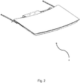
- Fig. 2 shows a perspective view of the assembled components of Fig. 1 .
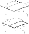
- Fig. 3 shows a perspective view of the sliding roof panel assembly 8 when it is in a closed and lowered configuration.
- the roof panel 14 is in a closed and lowered position where the roof panel 14 covers, and is lowered towards, an opening in a roof.
- the roof panel frame 28 contacts and compresses the seal 32.
- Fig. 4 shows a perspective view of the sliding roof panel assembly 8 when it is in an open and lifted configuration. In this position, the roof panel 14 is in an open and lifted position and is lifted and tilted to allow movement along the slide guide 16.
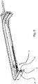
- Fig. 5 shows a perspective view of the slide assembly 10 in a closed and lowered configuration in relation to the base frame 30 and the roof panel frame 28. In this configuration, the roof panel frame 28 contacts and compresses seal 32.
- Fig. 6 shows a perspective view of the slide assembly 10.
- the slide assembly 10 includes a drive slide 34 and a connector 42.
- a first lever 36 rotatably links the drive slide 34 to the connector 42.
- the first lever 36 is rotatably attached to the drive slide 34 by a first pivot 38, near a first end 40 of the first lever 36.
- the first lever 36 is rotatably attached to the connector 42 by a connector pivot 45, near a second end 44 of the first lever 36.
- the connector 42 is rotatably attached to the roof panel 14 by an attaching member 46.
- a guide rail follower 48 is rotatably attached to the connector 42 by the connector pivot 45.
- the guide rail follower 48 is supported by slide guide 16 and supports the weight of the roof panel 14.
- the drive slide 34 is driven along the slide guide 16 by drive cable 18.
- the drive cable 18 is attached to the drive slide 34 by a cable attachment 50.
- the slide assembly 10 includes a slave slide 52 which leads or follows the drive slide 34 in the slide track 63 (depending on the direction of movement).
- a second lever 54 rotatably links the slave slide 52 to the connector 42.
- the second lever 54 is rotatably attached to the slave slide 52 by a second pivot 56, near a first end 58 of the second lever 54.
- the second lever 54 is rotatably attached to the connector 42 by the connector pivot 45 near a second end 59 of the second lever 54.
- the drive slide 34 and the slave slide 52 are linked by elastic members (springs) 60.
- the elastic members 60 are attached to the drive slide 34 and the slave slide 52 by pins 57.
- the connector 42 is attached to the attaching member 46 by securing members 62 that are inserted into securing apertures 64 in the connector 42 when the connector 42 is inserted into the attaching member 46.
- Figs. 7 and 8 show perspective views of the slide assembly 10 in a lifted configuration.
- the slide assembly 10 is arranged so that the drive slide 34 is driveably moveable on a slide track 63 in the slide guide 16.
- the slave slide 52 follows the drive slide 34 and is slideably moveable on the slide track 63. Both the drive slide 34 and slave slide 52 can slide along the slide track 63 in a forward direction 65 and a rearward direction 61.
- the slide guide 16 includes a guide rail 66, the guide rail 66 having a rearward raised portion 67 and a forward depressed portion 68.
- the guide rail 66 supports the guide rail follower 48 so that the guide rail follower 48 can travel along the guide rail 66. In this configuration, the guide rail follower 48 is supported on the rearward raised portion 67 and the drive slide 34 and the slave slide 52 are positioned together.
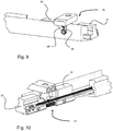
- Figs. 9 and 10 show perspective views of the slide assembly 10 in a lowered configuration.
- the guide rail follower 48 has travelled along the forward depressed portion 68 and the drive slide 34 is positioned apart from the slave slide 52.
- Figs. 11 and 12 show a front view and perspective view respectively of the slide assembly 10 in a lifted configuration.
- Fig. 13 shows a cutaway front view of the sliding roof panel assembly 8 in a closed and lowered position.
- the base frame 30 is fixed to a base structure 70 that defines a roof opening, such as the deck of a marine vessel.
- the seal 32 is attached to an upper surface 72 of the base frame 30 so that when the roof panel 14 is lowered, the roof panel frame 28 contacts and compresses the seal 32.
- the slide guide bracket 24 fixes the slide guide 16 to the base frame 30.
- the attaching member 46 attaches the roof panel frame 28 to the connector 42.
- the drive cable 18 is housed in a drive cable channel 73 which runs along the slide guide 16.
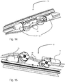
- Figs. 14 and 15 show perspective views of the drive motor assembly 12 and Fig. 16 shows a schematic plan view of the drive motor assembly 12.
- the drive motor assembly 12 includes drive motors 74 which drive the drive cables 18.
- the drive cables 18 are preferably comprise a helical protrusion extending from their outer circumference. The helical protrusions engage with gears driven by the drive motors 74.
- Each drive cable 18 is attached to a drive slide 34 and is configured to move the drive slide 34 along the slide guide 16 when driven by the respective drive motor 74.
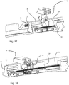
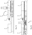
- Figs. 17 , 19 and 21 show perspective, side and front views respectively of the slide assembly 10 within the slide guide 16 in a lifted configuration.
- Figs. 18 , 20 and 22 show perspective, side and front views respectively of the slide assembly 10 within the slide guide 16 in a lowered configuration.
- a lock 76 is fixed to the slide guide 16.
- the drive slide 34 is configured to have a bypass aperture 78 through which the lock 76 passes when the drive slide 34 travels within the slide guide 16.
- the lock 76 contacts the slave slide 52 and restricts further forward movement of the slave slide 52 along the slide guide 16 when the sliding roof panel assembly is in the covered and sealed position.
- Fig. 3 shows the sliding roof panel assembly 8 in a closed and lowered configuration, where the roof panel 14 is in a closed and lowered positioned to cover a roof opening. In this position, the roof panel 14 is at its furthest point forward and is lowered towards the roof opening so that the roof panel frame 28 contacts and compresses the seal 32 (not shown).
- Fig. 4 shows the sliding roof panel assembly 8 in an uncovered position.
- the roof panel 14 has moved rearward to uncover a roof opening.
- the roof panel frame 28 is lifted away from the seal 32 and the base frame 30. This lifting action ensures the roof panel 14 can travel rearward without interference between the roof panel frame 28 and the base frame 30 to ensure there is no frictional contact between the roof panel frame 28 and the seal 32, which could cause the seal to wear.
- the roof panel 14 is attached to and driven by the slide assembly 10.
- the slide assembly 10 is driven by the drive cable 18 and the drive cable 18 is driven by the drive motor assembly 12.
- the drive motor 74 pushes the drive cable 18 and the drive cable 18 pushes the drive slide 34 forward on the slide track 63 in the slide guide 16.
- the drive motor 74 pulls the drive cable 18 which pulls the drive slide 34 rearward on the slide track 63 in the slide guide 16.
- the slide assembly 10 When the roof panel 14 is in the closed and lowered position, as in Fig. 3 , the slide assembly 10 is in the lowered configuration.
- the guide rail follower 48 is positioned on the forward depressed portion 68 of the guide rail 66.
- the slide assembly 10 When the roof panel 14 is in a closed and lowered position, if the drive slide 34 is driven rearward, the slide assembly 10 begins to move rearwards along the slide track 63.
- the guide rail follower 48 travels upwardly along the forward depressed portion 68 relative to the drive slide 34 by reaction of the forward depressed portion 68 and rotation of the first lever 36, until the guide rail follower 48 reaches the rearward raised portion 67 of the guide rail 66.
- the roof panel 14 follows the movement of the guide rail follower 48 upwardly towards the open and lifted position.
- the slide assembly When the roof panel 14 is in is the open and lifted position, as in Fig. 4 , the slide assembly is in the lifted configuration.
- the guide rail follower 48 is positioned on rearward raised portion 67 of the guide rail 66.
- the drive slide 34 is driven further rearward and the guide rail follower 48 travels along the rearward raised portion 67 of the guide rail 66.
- the roof panel 14 follows the movement of the guide rail follower 48.
- the slide assembly 10 When the roof panel 14 is in an open and lifted position, if the drive slide 34 is driven forward, the slide assembly 10 begins to move forwards along the slide track 63.
- the guide rail follower 48 travels along the rearward raised portion 67 of the guide rail 66 until it reaches the forward depressed portion 68.
- the guide rail follower 48 then travels downwardly along the forward depressed portion 68 of the guide rail 66 relative to the drive slide 34 by the weight of the roof panel 14 and rotation of the first lever 36.
- the roof panel 14 follows the movement of the guide rail follower 48 downwardly towards the closed and lowered position.
- the first lever 36 rotates about the first pivot 38 in the drive slide 34. There is only rotational movement between the first lever 36 and the drive slide 34. As such, there is no sliding friction between the first lever 36 and drive slide 34 and therefore less chance of material failure due to wearing. Because the roof panel 48 follows the guide rail follower 48 as the guide rail follower 48 travels downwardly and upwardly, the first lever 36 requires only two pivot points, as opposed to more than two in the prior art where the roof panel opposes the guide rail follower's movement. As such, the process of manufacturing, assembling and maintaining the slide assembly 10 is simple.
- the sliding roof panel assembly 8 includes a slave slide 52 as described above.
- the slave slide 52 follows the movement of the drive slide 34 in the slide track 63.
- the second lever 54 rotates accordingly and the drive slide 34 and the slave slide 52 are driven closer together within the slide track 63.
- the second lever 54 rotates accordingly and the drive slide 34 and the slave slide 52 are driven further apart within the slide track 63.
- the slave slide 52 and second lever 54 provide stability and balance to the sliding roof panel assembly 8 in use.
- the slave slide 52 and second lever 54 also help prevent the guide follower 48 from moving in a horizontal direction perpendicular to the direction of travel of the drive slide 34. This is because the second lever 54 provides an element of stiffness to the slide assembly, thereby helping to prevent the first lever 36 from pivoting in this horizontal direction.
- the drive slide 34 and the slave slide 52 are in contact or close to being in contact. This helps to restrict any further lifting of the roof panel 14 because the first lever 36 and the second lever 54 are prevented from rotating further towards a vertical orientation. This is particularly advantageous when the guide rail follower 48 is at risk of rattling or lifting from the guide rail 66, for example when the sliding panel assembly 8 is mounted on a marine vessel in rough seas.
- the lock 76 is attached to the slide guide 16 so that the lock 76 prevents the slave slide 52 from moving forward in the slide track 63 when roof panel 14 is in the closed and lowered position. This locks the roof panel 14 in the closed and lowered position when the drive slide 34 is prevented from moving in the slide track 63. This is particularly advantageous where a tight seal needs to be kept between the panel frame 28 and the base frame 30.
- lock 76 Another advantage of the lock 76 is that the sliding roof panel assembly can be used on an inclined plane where the weight of the roof panel 14 may not force the guide rail follower 48 into the slot 68. In this case, when the slave slide 52 contacts the lock 76, and as the drive slide 34 is driven forward, the roof panel 14 will be forced to a lowered position by rotation of the first lever 36 and the second lever 54.
- the drive slide 34 has a bypass aperture 78. As the drive slide 34 travels on the slide track 63, the bypass aperture 78 prevents contact between the lock 76 and the drive slide 34. This allows the drive slide 34 and the slave slide 52 to travel together in the slide track 63 when the lock 76 is statically fixed within the slide guide 16.
- the elastic member 60 links the drive slide 34 to the slave slide 52.
- the elastic member can bias the drive slide 34 and the slave slide 52 towards each other. This helps stabilise the slide assembly 10 as it travels along the slide guide 16 by preventing the slave slide 52 from trailing behind the drive slide 34. This biasing also helps to lift the roof panel 14 as the guide rail follower 48 travels upwardly along the forward depressed portion 68 of the guide rail 66 by forcing the respective rotation of the first lever arm 36 and the second lever arm 54. This reduces the force required to drive the drive slide 34 rearwards.
- the elastic member can bias the drive slide 34 and the slave slide 52 apart.
- This biasing provides a downward force on the guide rail follower 48 and, when the roof panel 14 is in the open and lifted position, this helps to prevent the guide follower 48 and the roof panel 14 from lifting.
- the elastic member 60 can bias the drive slide 34 and the slave slide 52 to an intermediate position so that both the above advantages are realised.
- the connector 42 connects the slide assembly 10 to the roof panel 14 the connector 42 defining a securing aperture 64.
- the slide assembly can be assembled with the slide guide 16 and, at a later time, the roof panel 14 can be lowered onto the connector 42 and secured with securing members 62.
- the connector 42 could be inserted into an attaching member 46.
- the drive slide 34 can be driven by the drive cable 18.
- the drive cable 18 is attached to the drive slide 34 by cable attachment 50.
- the drive cable 18 allows the drive slide 34 to be driven remotely by providing a force to the drive cable 18 at a distance away from the drive slide 34. This is particularly advantageous when access to the drive slide 34 is difficult, for example if the sliding roof panel assembly 8 is out of reach or a trim covers the drive slide 34.
- the drive cable 18 can be driven by engagement with a drive motor 74 in the drive motor assembly 12. This allows the roof panel 14 to opened and closed without manual effort by the operator. Additionally, the drive motor 74 can be activated remotely, which is particularly advantageous when the drive cable 18 is out of reach.
- the drive cable 18 can have a helical protrusion extending from its outer circumference. This helical protrusion can engage with a gear connected to the drive motor 74 which provides a more secure engagement, preventing the drive cable 18 from slipping past the drive motor 74. This is particularly advantageous when the roof panel 14 is heavy and a large driving force is required to move it.
- the drive cable 18 can be contained in a channel 73 in the slide guide 16.
- the channel 73 runs along the length of the slide guide 16 and allows the drive cable 18 to provide a pushing force to the drive slide 34 without buckling. Additionally, the channel 73 shields the drive cable 18, providing a safer and more aesthetically pleasing mechanism.
- the roof panel 14 can be supported by a support pivot 20 near rearward end of the roof panel 14. As the roof panel 14 moves from the lifted position to the lowered position (and vice versa), it pivots about the support pivot 20. This provides a stable and balanced movement.
- the support pivot 20 can slidably move on a support track 22. As the roof panel 14 moves in a forward and rearward direction, the support pivot 20 moves forwardly and rearwardly respectively on the support track 22. This allows the roof panel 14 to rotate and move forward (or backward) simultaneously. This also provides a stable and balanced movement.
- the drive slide 34 can be rotatably linked to the guide rail follower 48 and the connector 42 via the first lever 36.
- the connector pivot 45 is inserted through the first lever 36, the connector 42 and the guide rail follower 48.
- a common rotational axis shared between these components provides a more simple mechanism, reducing the number of parts and simplifying assembly.
- the slave slide 52 can be rotatably linked to the guide rail follower 48 and the connector 42 via the second lever 54.
- the connector pivot 45 is inserted through the second lever 54, the connector 42 and the guide rail follower 48.
- a common rotational axis shared between these components provides a more simple mechanism, reducing the number of parts and simplifying assembly.
Landscapes
- Engineering & Computer Science (AREA)
- Mechanical Engineering (AREA)
- Chemical & Material Sciences (AREA)
- Combustion & Propulsion (AREA)
- Ocean & Marine Engineering (AREA)
- Power-Operated Mechanisms For Wings (AREA)
Description
- The present invention relates to a sliding roof panel assembly and a method for the operation of such a sliding roof panel assembly. A suitable sliding roof panel is a sunroof. The present invention has particular, but not necessarily exclusive, application to marine applications such as for pleasure craft.
- An opening in a vehicle roof can be covered and uncovered using a sliding roof panel, referred to herein as a "panel". The panel may comprise light-transmitting material, such as glass. In known systems, the sliding panel can be moved to between a position in which the opening is sealingly closed and a position in which the opening is uncovered. Such systems typically move the panel in two stages. To uncover the opening, the panel is first lifted from a seal around the opening and then the panel is translated along a track progressively to uncover the opening. To enable this sequence of movements, known mechanisms typically require forced frictional interaction of complex parts which can result in wearing, particularly when the panel is heavy. Over time, this can result in decreased tolerances between parts which can cause seal failure, rattling and material failure. Additionally, the complexity, precision and material quality required by such parts add to the manufacturing cost.
- For example,
EP-A-2168798 discloses an assembly for covering an opening of a vehicle with a panel. The panel is slidably attached to guide rails which run alongside the opening. InEP-A-2168798 , the panel is guided at its forward end by a drive slide which is driven along the guide rails. A raising lever attached to the panel has first and second slide shafts which are driven along different respective movement paths by virtue of their travel along a specifically shaped channel in the drive slide and along a specifically shaped locator channel fixed with respect to the guide rail. In this way, the lever is rotated during the travel of the drive slide to lift (during opening of the panel) or lower (during closing of the opening) the panel with respect to the seal around the opening. - Although the arrangement disclosed in
EP-A-2168798 has particular utility in automotive applications, in which the panel of the sunroof is typically lightweight, it has limited utility in larger scale applications, such as where the panel has substantial mass, by virtue of its area (e.g. it is used to cover a large opening) and/or by virtue of its thickness (e.g. it is intended to be load-supporting, such as capable of being walked on). The use of the complex mechanism as disclosed inEP-A-2168798 would be expected to be unsuitable for such robust applications. -
JP S61 160319 - Accordingly, the present inventors have devised the present invention seeking to provide a scalable sliding closure mechanism that has comparatively simple operation and a method for the operation thereof, allowing low cost of manufacture, ease of assembly and ease of maintenance.
- The present invention has been devised in order to address at least one of the problems identified above. Preferably, the present invention reduces, ameliorates, avoids or overcomes at least one of the above problems.
- Accordingly, in a first preferred aspect, the present invention provides a sliding roof panel assembly for covering a roof opening, the sliding roof panel assembly comprising:
- a slide guide for attachment along one side of the roof opening;
- a roof panel which is slidably moveable between an open and lifted position and a closed and lowered position, the roof opening being covered by the roof panel in the closed and lowered position;
- a slide assembly guided for travel along the slide guide and supporting the roof panel,
wherein the slide guide has a slide track and a guide rail, the slide track and the guide rail each extending along the slide guide, the guide rail having a forward depressed portion and a rearward raised portion, - the slide assembly comprising:
- a drive slide driveably moveable along the slide track of the slide guide;
- a guide rail follower supported by and moveable along the guide rail, the guide rail follower supporting the roof panel;
- a first lever, linking the drive slide and the roof panel via respective rotatable links, wherein, in use, the roof panel is slidably moveable from the open and lifted position to the closed and lowered position by driving the drive slide forward in the slide track to move the guide rail follower forward along the rearward raised portion of the guide rail until the guide rail follower reaches the forward depressed portion of the guide rail, the guide rail follower travelling downwardly along the forward depressed portion of the guide rail relative to the drive slide by the weight of the roof panel and rotation of the first lever, the roof panel following the movement of the guide rail follower downwardly towards the closed and lowered position, the slide assembly further comprising:
- a slave slide moveable along the slide track of the slide guide with the drive slide;
and a second lever, linking the slave slide and the roof panel via respective rotatable links, the first and second levers thereby linking the slave slide and the drive slide,
wherein when the roof panel moves from the closed and lowered position to the open and lifted position, the second lever rotates accordingly and the drive slide and the slave slide are driven closer together within the slide track, and - when the roof panel moves from the open and lifted position to the closed and lowered position, the second lever rotates accordingly and the drive slide and the slave slide are driven apart within the slide track, and
- a slave slide moveable along the slide track of the slide guide with the drive slide;
- wherein the sliding roof panel assembly further comprises:
- a support pivot for attachment to a base structure surrounding the roof opening, the support pivot pivotally supporting the roof panel, wherein, in use, the roof panel pivots about the support pivot as the roof panel moves from a lifted position to a lowered position; and
- a support track attached to the base structure surrounding the roof opening, wherein, in use, the support pivot slidably moves along the support track and is guided by the support track as the roof panel moves from the open and lifted position to a closed and lowered position.
- In a second preferred aspect, the present invention provides a marine pleasure craft having a sliding roof panel assembly according to the first aspect.
- In a third preferred aspect, the present invention provides a method for the operation of the sliding roof panel assembly, the method comprising slidably moving the roof panel from the open and lifted position to the closed and lowered position by driving the drive slide forward in the slide track to move the guide rail follower forward along the rearward raised portion of the guide rail until the guide rail follower reaches the forward depressed portion of the guide rail, the guide rail follower travelling downwardly along the forward depressed portion of the guide rail relative to the drive slide by the weight of the roof panel and rotation of the first lever, the roof panel following the movement of the guide rail follower downwardly towards the closed and lowered position.
- The present invention therefore provides a sliding roof panel assembly for opening and closing an opening, such as on a marine pleasure craft, and a method for the operation thereof. Furthermore, the sliding roof panel assembly is scalable, simple in operation, has a low cost of manufacture, is easy to assemble and is easy to maintain.
- The first, second and/or third aspect of the invention may have any one or, to the extent that they are compatible, any combination of the following features.
- It is recognised by the inventors that the present invention may be used on static structures, such as buildings. It is therefore, not necessarily limited only to use on a marine pleasure craft, although such application is at the time of writing a preferred application.
- Preferably, the sliding roof panel assembly comprises more than one slide guide. Thus, a slide guide may be provided respectively on two opposing sides of the opening. In this case, the panel's weight can be shared between the slide guides. Distributing the panel's weight results in a more balanced and stable assembly.
- The sliding roof panel assembly further comprises a slave slide slidably moveable along the slide track of the slide guide with the drive slide. There is also provided a second lever, the second lever linking the slave slide and the roof panel via respective rotatable links. In this case, having the slave slide and the drive slide moving together in the slide track provide a more stable and balanced operation to the mechanism in use. The slave slide and second lever help prevent the guide follower and the roof panel from jumping vertically, as explained in more detail below.
- Preferably, when the assembly is in use moving the roof panel towards the open and lifted position, the slave slide is pushed along the slide track by the drive slide. The use of a slave slide helps prevent the guide follower and roof panel from being lifted when the roof panel is in the open and lifted position, preventing rattling and accidental further lifting of the panel, for example when the sliding panel assembly is mounted on a marine vessel in rough seas.
- Preferably, the sliding roof panel assembly further comprises a locking element disposed within the slide track for defining a forward limit of motion for the slave slide along the slide track when the roof panel is in the closed and lowered position. In this case, the roof panel is prevented from accidentally lifting and opening when in a closed and lowered position. This is useful for when a seal between the roof panel and a lower frame needs to be kept, for example when the assembly is inclined in use where the weight of the panel may not provide an adequate lowering and sealing force.
- Preferably, the drive slide has a bypass feature to permit the drive slide to travel forwardly of the locking element along the slide track. In this way, the position of the locking element may be fixed with respect to the track without interfering with the movement of the drive slide.
- Preferably, the sliding roof panel assembly comprises an elastic member linking the drive slide to the slave slide. The elastic member may substantially bias the drive slide and slave slide together which prevents the slave slide from moving in an unstable manner behind the drive slide when the slide assembly moves on the slide track. This biasing also helps lift the roof panel when the guide follower travels from the forward depressed portion to the rearward raised portion, thereby reducing the force required to drive the drive slide rearward. Alternatively, the elastic member may substantially bias the drive slide and the slave slide apart which helps to prevent the guide follower and the roof panel from lifting when the roof panel is in the open and lifted position. A suitable elastic member may be one or more springs.
- Preferably, the sliding roof panel assembly comprises: a connector linking the slide assembly to the panel; and a securing member, wherein the securing member is inserted through the connector to attach the connector to the roof panel. In this case, assembly is easier because the slide guide and slide assembly can be assembled together and the roof panel can simply be lowered onto the connector at a later time and secured easily with the securing member.
- Preferably, the sliding roof panel assembly further comprises a drive cable for driving the drive slide. In this case, the drive slide can be driven remotely. This is particularly advantageous when access to the drive slide is difficult, for example if a trim covers the slide guide.
- Preferably, the sliding roof panel assembly further comprises a drive motor which drives the drive cable. In this case, the roof panel can be opened and closed remotely and without manual effort by the operator.
- The drive cable may have a helical protrusion at its outer circumference, for driving engagement with the motor.
- Preferably, the drive cable is contained within a channel in the slide guide. In this case, the drive cable is prevented from buckling when the drive slide is driven forward. Additionally the drive cable is fully contained within the sliding roof panel assembly, which is safer and more aesthetically pleasing.
- The sliding roof panel assembly comprises a support pivot attached to a base structure surrounding the roof opening, the support pivot pivotally supporting the roof panel, wherein, in use, the roof panel pivots about the support pivot as the roof panel moves from a lifted position to a lowered position. In this case, the support pivot supports the panel as it rotates, resulting in a balanced and stable mechanism.
- The sliding roof panel assembly comprises a support track attached to the base structure surrounding the roof opening, wherein, in use, the support pivot slidably moves along the support track as the roof panel moves from the open and lifted position to a closed and lowered position. In this case, the roof panel is stably guided along the base structure as it moves forward and rearward.
- Preferably, the drive slide is rotatably linked to the guide rail follower via the first lever. In this case, assembly and maintenance is simplified and the number of parts is reduced.
- Preferably, the slave slide is rotatably linked to the guide rail follower via the second lever. In this case, assembly and maintenance is simplified and the number of parts is reduced.
- Preferably, the roof panel is made of a light-transmitting material. In this case, a room or cabin in which the sliding roof panel assembly is installed can receive light even when the panel covers the opening.
- Alternatively, the roof panel need not necessarily be formed of a light-transmitting material. For example, the roof panel may instead be formed of a composite material. In this case, the roof panel assembly has good structural integrity which is particularly advantageous in a marine environment. The composite material could be glass reinforced plastic (GRP).
- Preferably, the method for the operation of the sliding roof panel assembly further comprises slidably moving the roof panel from the closed and lowered position to the open and lifted position by driving the drive slide rearward in the slide track to move the guide rail follower rearward along the forward depressed portion of the guide rail, the guide rail follower travelling upwardly along the forward depressed portion of the guide rail relative to the drive slide by reaction of the forward depressed portion and rotation of the first lever until the guide rail follower reaches the rearward raised portion of the guide rail, the roof panel following the movement of the guide rail follower upwardly towards the open and lifted position.
- Further optional features of the invention are set out below.
- Embodiments of the invention will now be described by way of example with reference to the accompanying drawings in which:
-
Fig. 1 shows a perspective exploded view of a sliding roof panel assembly, including a slide guide, a slide assembly and a drive motor assembly, according to an embodiment of the invention. -
Fig. 2 shows a perspective view of an assembled sliding roof panel assembly ofFig. 1 . -
Fig. 3 shows a perspective view of the sliding roof panel assembly ofFig. 1 in a covered and sealed position. -
Fig. 4 shows a perspective view of the sliding roof panel assembly ofFig. 1 in an uncovered position. -
Fig. 5 shows a partial cutaway perspective view of the slide assembly ofFig. 1 and the surrounding structure -
Fig. 6 shows a perspective exploded view of a slide assembly for use in an embodiment of the invention. -
Fig. 7 shows a perspective view of a slide guide containing the slide assembly ofFig. 6 in a lifted configuration. -
Fig. 8 shows a perspective view of a slide guide containing the slide assembly ofFig. 6 in a lifted configuration with a partial cutaway from a different direction compared withFig. 7 . -
Fig. 9 shows a perspective view of the slide guide containing the slide assembly ofFig. 6 in a lowered configuration. -
Fig. 10 shows a perspective view of the slide guide containing the slide assembly ofFig. 6 in a lowered configuration with part of the slide guide cut away. -
Fig. 11 shows a front cross sectional view of the slide guide containing the slide assembly ofFig. 6 in a lifted configuration -
Fig. 12 shows in enlarged view the arrangement shown inFig. 8 . -
Fig. 13 shows a cross sectional front view of the sliding roof panel assembly ofFig. 1 in a lowered position. -
Fig. 14 shows a perspective view of the drive motor assembly ofFig. 1 . -
Fig. 15 shows another perspective view of the drive motor assembly ofFig. 1 . -
Fig. 16 shows a schematic plan view of the drive motor assembly ofFig. 1 . -
Fig. 17 shows a perspective view of the slide guide containing a slide assembly according to an embodiment of the invention, the assembly being in a lifted configuration and being provided with a locking element. -
Fig. 18 shows a perspective view of the slide guide ofFig. 17 but in a lowered configuration. -
Fig. 19 shows a side view of the slide guide ofFig. 17 in a lifted configuration. -
Fig. 20 shows a side view of the slide guide ofFig. 17 but in a lowered configuration. -
Fig. 21 shows a front view of the slide guide ofFig. 17 in a lifted configuration. -
Fig. 22 shows a front view of the slide guide ofFig. 17 but in a lowered configuration. - The preferred embodiments of the present invention provide a sliding roof panel assembly that is configured to move a roof panel from an open and lifted position to a closed and lowered position, and vice versa, where the sliding roof panel assembly is mechanically simple and scalable. The specific constructional details of the preferred embodiments will be discussed in more detail below. First, it is possible to set out some advantages of the preferred embodiments compared with known sliding panel assemblies.
- It should be noted that, throughout this document, a forward direction is the direction in which the drive slide travels as the roof panel moves to a closed and lowered position. Similarly, a rearward direction is the direction in which the drive slide travels as the roof panel moves to an open and lifted position. An upward direction is the direction in which the roof panel substantially travels when it is raised away from an opening. Similarly, a downward direction is the direction in which the roof panel substantially travels when it is lowered towards an opening. These directions may not necessarily correlate with forwards and rearwards directions on a marine craft on which the assembly may be used.
- The use of a sliding roof panel assembly according to the preferred embodiments reduces the likelihood of material failure and also simplifies the manufacturing, assembly and maintenance processes, compared with the prior art disclosures. The use of complex machined components can be avoided by using a drive slide rotatably linked to a roof panel via a lever arm and using a roof panel that is supported by a guide rail follower and that follows the downwards movement of the guide rail follower. Conversely, prior art disclosures (such as
EP-A-2168798 ) use a mechanism where a roof panel follows a movement opposite to the movement of a guide rail follower. This movement requires more complex components to carry out because, for example inEP-A-2168798 , it is essential to have more than two pivot points on the lever between drive slide and the roof panel. - The simple components of the present sliding roof panel assembly allow the use of simpler machining processes and may require less material, thereby reducing the overall cost of manufacture. Furthermore, given the smaller number of components, such an assembly is easy to assemble and maintain. The assembly can also be scaled easily as the size and the weight of the roof panel is increased. This means the mechanism works just as well for small panels (for example, on the roof of a small car) as it does for large panels (for example, on the roof of a large marine pleasure craft or a building). The complex nature of the prior art mechanisms means that they would be difficult to adapt to heavier panels and would require substantial redesign to ensure the mechanism is suitable.
- A slave slide and second lever within the slide assembly give a more stable and balanced mechanism in use. The slave slide and second lever help prevent the guide follower and the roof panel from moving in a horizontal direction perpendicular to the direction of travel of the drive slide. Additionally, when the slave slide abuts the drive slide, the roof panel is prevented from lifting when the sliding roof panel assembly is in an uncovered position, thereby preventing rattling and unwanted lifting of the roof panel.
- A lock in the sliding roof panel assembly, in combination with the slave slide and second lever, gives a simple mechanism by which a seal can be tightened and held when the roof panel is in the closed and lowered position. In prior art disclosures, this problem is solved by providing complex channels in the drive slide which are costly to design and manufacture and are difficult to scale.
- In the drawings, features are indicated using reference numerals. Where the same feature is shown in more than one drawing, the reference numeral may be omitted if it has already been described with reference to an earlier drawing.
-
Fig. 1 shows a perspective view of a slidingroof panel assembly 8 according to an embodiment of the invention. The sliding roof panel assembly has a pair of mirror image slide guides 16 which each comprise aslide assembly 10. The slide guides 16 are attached to abase frame 30 byslide guide brackets 24. In some embodiments, theslide guide brackets 24 are fixed in a nonadjustable manner to the slide guides 16 andbase frame 30. Thebase frame 30 is secured to a base structure (not shown inFig. 1 , but which may be the deck of a boat). Aseal 32 is attached to an upper surface of thebase frame 30. Aroof panel 14 is mounted on aroof panel frame 28. Theroof panel frame 28 is attached to theslide assemblies 10 and, when in a covered and sealed position, contacts and compresses theseal 32 on thebase frame 30. Theroof panel frame 28 is pivotally attached to supportpivots 20 byroof panel brackets 26. The support pivots 20 are slidably disposed on support tracks 22. The support tracks 22 are fixed to the base structure. Theslide assemblies 10 are driven bydrive cables 18, thedrive cables 18 being driven by adrive motor assembly 12. - The sliding roof panel assembly described and illustrated here has two slide guides 16, in order to distribute the weight of the roof panel and provide stable operation.
-
Fig. 2 shows a perspective view of the assembled components ofFig. 1 . -
Fig. 3 shows a perspective view of the slidingroof panel assembly 8 when it is in a closed and lowered configuration. In this configuration, theroof panel 14 is in a closed and lowered position where theroof panel 14 covers, and is lowered towards, an opening in a roof. When lowered, theroof panel frame 28 contacts and compresses theseal 32. -
Fig. 4 shows a perspective view of the slidingroof panel assembly 8 when it is in an open and lifted configuration. In this position, theroof panel 14 is in an open and lifted position and is lifted and tilted to allow movement along theslide guide 16. -
Fig. 5 shows a perspective view of theslide assembly 10 in a closed and lowered configuration in relation to thebase frame 30 and theroof panel frame 28. In this configuration, theroof panel frame 28 contacts and compressesseal 32. -
Fig. 6 shows a perspective view of theslide assembly 10. Theslide assembly 10 includes adrive slide 34 and aconnector 42. Afirst lever 36 rotatably links thedrive slide 34 to theconnector 42. Thefirst lever 36 is rotatably attached to thedrive slide 34 by afirst pivot 38, near afirst end 40 of thefirst lever 36. Thefirst lever 36 is rotatably attached to theconnector 42 by aconnector pivot 45, near asecond end 44 of thefirst lever 36. Theconnector 42 is rotatably attached to theroof panel 14 by an attachingmember 46. Aguide rail follower 48 is rotatably attached to theconnector 42 by theconnector pivot 45. Theguide rail follower 48 is supported byslide guide 16 and supports the weight of theroof panel 14. Thedrive slide 34 is driven along theslide guide 16 bydrive cable 18. Thedrive cable 18 is attached to thedrive slide 34 by a cable attachment 50. - The
slide assembly 10 includes aslave slide 52 which leads or follows thedrive slide 34 in the slide track 63 (depending on the direction of movement). Asecond lever 54 rotatably links theslave slide 52 to theconnector 42. Thesecond lever 54 is rotatably attached to theslave slide 52 by asecond pivot 56, near afirst end 58 of thesecond lever 54. Thesecond lever 54 is rotatably attached to theconnector 42 by theconnector pivot 45 near asecond end 59 of thesecond lever 54. - Preferably, the
drive slide 34 and theslave slide 52 are linked by elastic members (springs) 60. Theelastic members 60 are attached to thedrive slide 34 and theslave slide 52 bypins 57. - Preferably, the
connector 42 is attached to the attachingmember 46 by securingmembers 62 that are inserted into securingapertures 64 in theconnector 42 when theconnector 42 is inserted into the attachingmember 46. -
Figs. 7 and 8 show perspective views of theslide assembly 10 in a lifted configuration. Theslide assembly 10 is arranged so that thedrive slide 34 is driveably moveable on aslide track 63 in theslide guide 16. Theslave slide 52 follows thedrive slide 34 and is slideably moveable on theslide track 63. Both thedrive slide 34 and slave slide 52 can slide along theslide track 63 in aforward direction 65 and arearward direction 61. Theslide guide 16 includes aguide rail 66, theguide rail 66 having a rearward raisedportion 67 and a forwarddepressed portion 68. Theguide rail 66 supports theguide rail follower 48 so that theguide rail follower 48 can travel along theguide rail 66. In this configuration, theguide rail follower 48 is supported on the rearward raisedportion 67 and thedrive slide 34 and theslave slide 52 are positioned together. -
Figs. 9 and 10 show perspective views of theslide assembly 10 in a lowered configuration. In this configuration, theguide rail follower 48 has travelled along the forwarddepressed portion 68 and thedrive slide 34 is positioned apart from theslave slide 52. -
Figs. 11 and 12 show a front view and perspective view respectively of theslide assembly 10 in a lifted configuration. -
Fig. 13 shows a cutaway front view of the slidingroof panel assembly 8 in a closed and lowered position. Thebase frame 30 is fixed to abase structure 70 that defines a roof opening, such as the deck of a marine vessel. Theseal 32 is attached to anupper surface 72 of thebase frame 30 so that when theroof panel 14 is lowered, theroof panel frame 28 contacts and compresses theseal 32. Theslide guide bracket 24 fixes theslide guide 16 to thebase frame 30. The attachingmember 46 attaches theroof panel frame 28 to theconnector 42. Thedrive cable 18 is housed in adrive cable channel 73 which runs along theslide guide 16. -
Figs. 14 and 15 show perspective views of thedrive motor assembly 12 andFig. 16 shows a schematic plan view of thedrive motor assembly 12. Thedrive motor assembly 12 includesdrive motors 74 which drive thedrive cables 18. Thedrive cables 18 are preferably comprise a helical protrusion extending from their outer circumference. The helical protrusions engage with gears driven by thedrive motors 74. Eachdrive cable 18 is attached to adrive slide 34 and is configured to move thedrive slide 34 along theslide guide 16 when driven by therespective drive motor 74. -
Figs. 17 ,19 and21 show perspective, side and front views respectively of theslide assembly 10 within theslide guide 16 in a lifted configuration.Figs. 18 ,20 and22 show perspective, side and front views respectively of theslide assembly 10 within theslide guide 16 in a lowered configuration. Preferably, alock 76 is fixed to theslide guide 16. Thedrive slide 34 is configured to have abypass aperture 78 through which thelock 76 passes when thedrive slide 34 travels within theslide guide 16. Thelock 76 contacts theslave slide 52 and restricts further forward movement of theslave slide 52 along theslide guide 16 when the sliding roof panel assembly is in the covered and sealed position. - The principle of operation of the apparatus will now be explained.
-
Fig. 3 shows the slidingroof panel assembly 8 in a closed and lowered configuration, where theroof panel 14 is in a closed and lowered positioned to cover a roof opening. In this position, theroof panel 14 is at its furthest point forward and is lowered towards the roof opening so that theroof panel frame 28 contacts and compresses the seal 32 (not shown). -
Fig. 4 shows the slidingroof panel assembly 8 in an uncovered position. In this position, theroof panel 14 has moved rearward to uncover a roof opening. Here theroof panel frame 28 is lifted away from theseal 32 and thebase frame 30. This lifting action ensures theroof panel 14 can travel rearward without interference between theroof panel frame 28 and thebase frame 30 to ensure there is no frictional contact between theroof panel frame 28 and theseal 32, which could cause the seal to wear. - The
roof panel 14 is attached to and driven by theslide assembly 10. In preferred embodiments, theslide assembly 10 is driven by thedrive cable 18 and thedrive cable 18 is driven by thedrive motor assembly 12. To move theroof panel 14 to a closed and lowered position, thedrive motor 74 pushes thedrive cable 18 and thedrive cable 18 pushes thedrive slide 34 forward on theslide track 63 in theslide guide 16. To move theroof panel 14 to an open and lifted position, thedrive motor 74 pulls thedrive cable 18 which pulls thedrive slide 34 rearward on theslide track 63 in theslide guide 16. - When the
roof panel 14 is in the closed and lowered position, as inFig. 3 , theslide assembly 10 is in the lowered configuration. Theguide rail follower 48 is positioned on the forwarddepressed portion 68 of theguide rail 66. - When the
roof panel 14 is in a closed and lowered position, if thedrive slide 34 is driven rearward, theslide assembly 10 begins to move rearwards along theslide track 63. Theguide rail follower 48 travels upwardly along the forwarddepressed portion 68 relative to thedrive slide 34 by reaction of the forwarddepressed portion 68 and rotation of thefirst lever 36, until theguide rail follower 48 reaches the rearward raisedportion 67 of theguide rail 66. Theroof panel 14 follows the movement of theguide rail follower 48 upwardly towards the open and lifted position. - When the
roof panel 14 is in is the open and lifted position, as inFig. 4 , the slide assembly is in the lifted configuration. Theguide rail follower 48 is positioned on rearward raisedportion 67 of theguide rail 66. - To further open the
roof panel 14, thedrive slide 34 is driven further rearward and theguide rail follower 48 travels along the rearward raisedportion 67 of theguide rail 66. Theroof panel 14 follows the movement of theguide rail follower 48. - When the
roof panel 14 is in an open and lifted position, if thedrive slide 34 is driven forward, theslide assembly 10 begins to move forwards along theslide track 63. Theguide rail follower 48 travels along the rearward raisedportion 67 of theguide rail 66 until it reaches the forwarddepressed portion 68. Theguide rail follower 48 then travels downwardly along the forwarddepressed portion 68 of theguide rail 66 relative to thedrive slide 34 by the weight of theroof panel 14 and rotation of thefirst lever 36. Theroof panel 14 follows the movement of theguide rail follower 48 downwardly towards the closed and lowered position. - As the
roof panel 14 lifts and lowers, thefirst lever 36 rotates about thefirst pivot 38 in thedrive slide 34. There is only rotational movement between thefirst lever 36 and thedrive slide 34. As such, there is no sliding friction between thefirst lever 36 and driveslide 34 and therefore less chance of material failure due to wearing. Because theroof panel 48 follows theguide rail follower 48 as theguide rail follower 48 travels downwardly and upwardly, thefirst lever 36 requires only two pivot points, as opposed to more than two in the prior art where the roof panel opposes the guide rail follower's movement. As such, the process of manufacturing, assembling and maintaining theslide assembly 10 is simple. - The sliding
roof panel assembly 8 includes aslave slide 52 as described above. Theslave slide 52 follows the movement of thedrive slide 34 in theslide track 63. As theroof panel 14 moves from the closed and lowered position to the open and lifted position, thesecond lever 54 rotates accordingly and thedrive slide 34 and theslave slide 52 are driven closer together within theslide track 63. As theroof panel 14 moves from the open and lifted position to the closed and lowered position, thesecond lever 54 rotates accordingly and thedrive slide 34 and theslave slide 52 are driven further apart within theslide track 63. Theslave slide 52 andsecond lever 54 provide stability and balance to the slidingroof panel assembly 8 in use. Theslave slide 52 andsecond lever 54 also help prevent theguide follower 48 from moving in a horizontal direction perpendicular to the direction of travel of thedrive slide 34. This is because thesecond lever 54 provides an element of stiffness to the slide assembly, thereby helping to prevent thefirst lever 36 from pivoting in this horizontal direction. - When the
roof panel 14 is in the open and lifted position, thedrive slide 34 and theslave slide 52 are in contact or close to being in contact. This helps to restrict any further lifting of theroof panel 14 because thefirst lever 36 and thesecond lever 54 are prevented from rotating further towards a vertical orientation. This is particularly advantageous when theguide rail follower 48 is at risk of rattling or lifting from theguide rail 66, for example when the slidingpanel assembly 8 is mounted on a marine vessel in rough seas. - The
lock 76 is attached to theslide guide 16 so that thelock 76 prevents the slave slide 52 from moving forward in theslide track 63 whenroof panel 14 is in the closed and lowered position. This locks theroof panel 14 in the closed and lowered position when thedrive slide 34 is prevented from moving in theslide track 63. This is particularly advantageous where a tight seal needs to be kept between thepanel frame 28 and thebase frame 30. - Another advantage of the
lock 76 is that the sliding roof panel assembly can be used on an inclined plane where the weight of theroof panel 14 may not force theguide rail follower 48 into theslot 68. In this case, when the slave slide 52 contacts thelock 76, and as thedrive slide 34 is driven forward, theroof panel 14 will be forced to a lowered position by rotation of thefirst lever 36 and thesecond lever 54. - The
drive slide 34 has abypass aperture 78. As thedrive slide 34 travels on theslide track 63, thebypass aperture 78 prevents contact between thelock 76 and thedrive slide 34. This allows thedrive slide 34 and theslave slide 52 to travel together in theslide track 63 when thelock 76 is statically fixed within theslide guide 16. - The
elastic member 60 links thedrive slide 34 to theslave slide 52. In one embodiment, the elastic member can bias thedrive slide 34 and theslave slide 52 towards each other. This helps stabilise theslide assembly 10 as it travels along theslide guide 16 by preventing the slave slide 52 from trailing behind thedrive slide 34. This biasing also helps to lift theroof panel 14 as theguide rail follower 48 travels upwardly along the forwarddepressed portion 68 of theguide rail 66 by forcing the respective rotation of thefirst lever arm 36 and thesecond lever arm 54. This reduces the force required to drive thedrive slide 34 rearwards. In another embodiment, the elastic member can bias thedrive slide 34 and theslave slide 52 apart. This biasing provides a downward force on theguide rail follower 48 and, when theroof panel 14 is in the open and lifted position, this helps to prevent theguide follower 48 and theroof panel 14 from lifting. In another embodiment, theelastic member 60 can bias thedrive slide 34 and theslave slide 52 to an intermediate position so that both the above advantages are realised. - The
connector 42 connects theslide assembly 10 to theroof panel 14 theconnector 42 defining a securingaperture 64. During assembly, the slide assembly can be assembled with theslide guide 16 and, at a later time, theroof panel 14 can be lowered onto theconnector 42 and secured with securingmembers 62. Theconnector 42 could be inserted into an attachingmember 46. - The
drive slide 34 can be driven by thedrive cable 18. Thedrive cable 18 is attached to thedrive slide 34 by cable attachment 50. Thedrive cable 18 allows thedrive slide 34 to be driven remotely by providing a force to thedrive cable 18 at a distance away from thedrive slide 34. This is particularly advantageous when access to thedrive slide 34 is difficult, for example if the slidingroof panel assembly 8 is out of reach or a trim covers thedrive slide 34. - The
drive cable 18 can be driven by engagement with adrive motor 74 in thedrive motor assembly 12. This allows theroof panel 14 to opened and closed without manual effort by the operator. Additionally, thedrive motor 74 can be activated remotely, which is particularly advantageous when thedrive cable 18 is out of reach. - The
drive cable 18 can have a helical protrusion extending from its outer circumference. This helical protrusion can engage with a gear connected to thedrive motor 74 which provides a more secure engagement, preventing thedrive cable 18 from slipping past thedrive motor 74. This is particularly advantageous when theroof panel 14 is heavy and a large driving force is required to move it. - The
drive cable 18 can be contained in achannel 73 in theslide guide 16. Thechannel 73 runs along the length of theslide guide 16 and allows thedrive cable 18 to provide a pushing force to thedrive slide 34 without buckling. Additionally, thechannel 73 shields thedrive cable 18, providing a safer and more aesthetically pleasing mechanism. - The
roof panel 14 can be supported by asupport pivot 20 near rearward end of theroof panel 14. As theroof panel 14 moves from the lifted position to the lowered position (and vice versa), it pivots about thesupport pivot 20. This provides a stable and balanced movement. - The
support pivot 20 can slidably move on asupport track 22. As theroof panel 14 moves in a forward and rearward direction, thesupport pivot 20 moves forwardly and rearwardly respectively on thesupport track 22. This allows theroof panel 14 to rotate and move forward (or backward) simultaneously. This also provides a stable and balanced movement. - The
drive slide 34 can be rotatably linked to theguide rail follower 48 and theconnector 42 via thefirst lever 36. During assembly, theconnector pivot 45 is inserted through thefirst lever 36, theconnector 42 and theguide rail follower 48. A common rotational axis shared between these components provides a more simple mechanism, reducing the number of parts and simplifying assembly. - The slave slide 52 can be rotatably linked to the
guide rail follower 48 and theconnector 42 via thesecond lever 54. During assembly, theconnector pivot 45 is inserted through thesecond lever 54, theconnector 42 and theguide rail follower 48. A common rotational axis shared between these components provides a more simple mechanism, reducing the number of parts and simplifying assembly. - While the invention has been described in conjunction with the exemplary embodiments described above, many equivalent modifications and variations will be apparent to those skilled in the art when given this disclosure. Accordingly, the exemplary embodiments of the invention set forth above are considered to be illustrative and not limiting.
Claims (13)
- A sliding roof panel assembly (8) for covering a roof opening, the sliding roof panel assembly (8) comprising:a slide guide (16) for attachment along one side of the roof opening;a roof panel (14) which is slidably moveable between an open and lifted position and a closed and lowered position, the roof opening being covered by the roof panel (14) in the closed and lowered position;a slide assembly (10) guided for travel along the slide guide (16) and supporting the roof panel (14),wherein the slide guide (16) has a slide track (63) and a guide rail (66), the slide track (63) and the guide rail (66) each extending along the slide guide (16), the guide rail (66) having a forward depressed portion (68) and a rearward raised portion (67),the slide assembly (10) comprising:a drive slide (34) driveably moveable along the slide track (63) of the slide guide (16);a guide rail follower (48) supported by and moveable along the guide rail (66), the guide rail follower (48) supporting the roof panel (14);a first lever (36), linking the drive slide (34) and the roof panel (14) via respective rotatable links,
wherein, in use, the roof panel (14) is slidably moveable from the open and lifted position to the closed and lowered position by driving the drive slide (34) forward in the slide track (63) to move the guide rail follower (48) forward along the rearward raised portion (67) of the guide rail (66) until the guide rail follower (48) reaches the forward depressed portion (68) of the guide rail (66), the guide rail follower (48) travelling downwardly along the forward depressed portion (68) of the guide rail (66) relative to the drive slide (34) by the weight of the roof panel (14) and rotation of the first lever (36), the roof panel (14) following the movement of the guide rail follower (48) downwardly towards the closed and lowered position,
the slide assembly further comprising:a slave slide (52) moveable along the slide track (63) of the slide guide (16) with the drive slide (34); anda second lever (54), linking the slave slide (52) and the roof panel (14) via respective rotatable links, the first (36) and second levers (54) thereby linking the slave slide (52) and the drive slide (34), wherein when the roof panel (14) moves from the closed and lowered position to the open and lifted position, the second lever (54) rotates accordingly and the drive slide (34) and the slave slide (52) are driven closer together within the slide track (63), and when the roof panel (14) moves from the open and lifted position to the closed and lowered position, the second lever (54) rotates accordingly and the drive slide (34) and the slave slide (52) are driven apart within the slide track (63);a support pivot (20) for attachment to a base structure surrounding the roof opening, the support pivot (20) pivotally supporting the roof panel (14), wherein, in use, the roof panel pivots about the support pivot (20) as the roof panel (14) moves from a lifted position to a lowered position; andcharacterised in that the slide assembly further comprises a support track (22) attached to the base structure surrounding the roof opening, wherein, in use, the support pivot (20) slidably moves along the support track (22) and is guided by the support track (22) as the roof panel (14) moves from the open and lifted position to a closed and lowered position. - A sliding roof panel assembly according to claim 1 having two of said slide guides (16), each for attachment respectively along opposing sides of the roof opening.
- A sliding roof panel assembly according to claim 1 or 2 wherein, in use moving the roof panel towards the open and lifted position, the slave slide is pushed along the slide track by the drive slide.
- A sliding roof panel assembly (8) according to claim 3 further comprising a locking element (76) disposed within the slide track (63) for defining a forward limit of motion for the slave slide (52) along the slide track (63) when the roof panel (14) is in the closed and lowered position, wherein the drive slide (34) optionally has a bypass feature (78) to permit the drive slide (34) to travel forwardly of the locking element (76) along the slide track (63).
- A sliding roof panel assembly (8) according to claim 3 or claim 4 further comprising an elastic member (60) linking the drive slide (34) and the slave slide (52).
- A sliding roof panel assembly (8) according to any one of claims 1 to 5 further comprising:a connector linking the slide assembly (10) to the panel (14); anda securing member,wherein the securing member is inserted through the connector to attach the connector to the roof panel (14).
- A sliding roof panel assembly according to any one of claims 1 to 6 wherein the drive slide (34) is rotatably linked to the guide rail follower (48) via the first lever (36).
- A sliding roof panel assembly according to claim 3 or according to any one of claims 4 to 7 as dependent from claim 3, wherein the slave slide is rotatably linked to the guide rail follower via the second lever.
- A marine pleasure craft having a sliding roof panel assembly (8) according to any one of claims 1 to 8.
- A marine pleasure craft according to claim 9 wherein the sliding roof panel assembly (8) is fitted so as to move from the closed and lowered position to the open and lifted position in a direction from a stern of the craft towards a bow of the craft.
- A marine pleasure craft according to claim 9 wherein the sliding roof panel assembly (8) is fitted so as to move from the closed and lowered position to the open and lifted position in a direction from a bow of the craft towards a stern of the craft.
- A method for the operation of the sliding roof panel assembly (8) according to any one of claims 1 to 8, the method comprising slidably moving the roof panel (14) from the open and lifted position to the closed and lowered position by driving the drive slide (34) forward in the slide track (63) to move the guide rail follower (48) forward along the rearward raised portion (67) of the guide rail (66) until the guide rail follower (48) reaches the forward depressed portion (68) of the guide rail (66), the guide rail follower (48) travelling downwardly along the forward depressed portion (68) of the guide rail (66) relative to the drive slide (34) by the weight of the roof panel (14) and rotation of the first lever (36), the roof panel (14) following the movement of the guide rail follower (48) downwardly towards the closed and lowered position.
- A method according to claim 12, the method comprising slidably moving the roof panel (14) from the closed and lowered position to the open and lifted position by driving the drive slide (34) rearward in the slide track (63) to move the guide rail follower (48) rearward along the forward depressed portion (68) of the guide rail (66), the guide rail follower (48) travelling upwardly along the forward depressed portion (68) of the guide rail (66) relative to the drive slide (34) by reaction of the forward depressed portion (68) and rotation of the first lever (36) until the guide rail follower (48) reaches the rearward raised portion (67) of the guide rail (66), the roof panel (14) following the movement of the guide rail follower (48) upwardly towards the open and lifted position.
Applications Claiming Priority (1)
| Application Number | Priority Date | Filing Date | Title |
|---|---|---|---|
| GB1704534.5A GB2560733A (en) | 2017-03-22 | 2017-03-22 | Sliding roof panel assembly and method for its operation |
Publications (2)
| Publication Number | Publication Date |
|---|---|
| EP3378687A1 EP3378687A1 (en) | 2018-09-26 |
| EP3378687B1 true EP3378687B1 (en) | 2020-11-04 |
Family
ID=58688440
Family Applications (1)
| Application Number | Title | Priority Date | Filing Date |
|---|---|---|---|
| EP18161100.5A Active EP3378687B1 (en) | 2017-03-22 | 2018-03-09 | Sliding roof panel assembly and method for its operation |
Country Status (7)
| Country | Link |
|---|---|
| US (1) | US10894580B2 (en) |
| EP (1) | EP3378687B1 (en) |
| AU (1) | AU2018201860B2 (en) |
| CA (1) | CA2997997C (en) |
| ES (1) | ES2847224T3 (en) |
| GB (1) | GB2560733A (en) |
| NZ (1) | NZ740674A (en) |
Families Citing this family (2)
| Publication number | Priority date | Publication date | Assignee | Title |
|---|---|---|---|---|
| DE102019117512B4 (en) * | 2019-06-28 | 2026-01-22 | Webasto SE | Sliding lid arrangement for a water-bound vehicle |
| TW202518631A (en) | 2023-07-14 | 2025-05-01 | 荷蘭商Asm Ip私人控股有限公司 | Lid moving system, enclosure, and method of moving lid |
Family Cites Families (19)
| Publication number | Priority date | Publication date | Assignee | Title |
|---|---|---|---|---|
| US4650243A (en) * | 1983-08-26 | 1987-03-17 | Sky-Top Sunroofs, Ltd. | Sliding and venting sunroof |
| JPS6071327A (en) * | 1983-09-29 | 1985-04-23 | Johnan Seisakusho Co Ltd | Opening and closing method for car sun roof and device thereof |
| JPS6171217A (en) * | 1984-09-17 | 1986-04-12 | Aichi Mach Ind Co Ltd | Closing device for car sum roof |
| JPS6171216A (en) * | 1984-09-17 | 1986-04-12 | Aichi Mach Ind Co Ltd | Closing device for car sun roof |
| JPS61160319A (en) * | 1985-01-10 | 1986-07-21 | Oi Seisakusho Co Ltd | Closing method and device for sliding roof |
| JPS61205514A (en) * | 1985-03-11 | 1986-09-11 | Oi Seisakusho Co Ltd | On-off gear for sliding roof |
| DE3536184C1 (en) * | 1985-10-10 | 1986-11-20 | Bayerische Motoren Werke AG, 8000 München | Sunroof for a motor vehicle, especially a passenger car |
| DE3840694A1 (en) * | 1988-03-10 | 1990-06-07 | Webasto Ag Fahrzeugtechnik | FAN ROOF FOR MOTOR VEHICLES |
| DE3908645C1 (en) * | 1989-03-16 | 1990-06-13 | Rockwell Golde Gmbh, 6000 Frankfurt, De | |
| JP2935872B2 (en) * | 1990-05-29 | 1999-08-16 | 玉置 輝男 | Aluminum vapor-deposited foil transfer processing method for textile products and textile products subjected to the aluminum-deposited foil transfer processing |
| US6199944B1 (en) * | 1999-06-04 | 2001-03-13 | Asc Incorporated | Spoiler sunroof |
| DE10037035B4 (en) * | 2000-07-27 | 2007-12-27 | Webasto Ag | Vehicle roof with at least one movable sunroof cover |
| US7255385B2 (en) * | 2002-10-18 | 2007-08-14 | Heuliez | Convertible roof for vehicle and associated vehicle |
| DE102004018461A1 (en) * | 2004-04-16 | 2005-11-03 | Arvinmeritor Gmbh | sliding roof system |
| DE102005043019B4 (en) * | 2005-09-09 | 2008-02-14 | Webasto Ag | Vehicle roof with at least two cover elements |
| DE102005059287B4 (en) * | 2005-12-12 | 2007-10-18 | Webasto Ag | Vehicle roof with at least one above a fixed vehicle roof sliding cover |
| US7780228B2 (en) * | 2008-09-12 | 2010-08-24 | Specialty Vehicle Acquisition Corp. | Automotive vehicle open air system |
| DK2168798T3 (en) * | 2008-09-26 | 2014-11-10 | Webasto SE | Shooting roof mechanism |
| FR2969539B1 (en) * | 2010-12-23 | 2013-01-11 | Webasto Systemes Carrosserie | SLIDING ROOF FOR A MOTOR VEHICLE |
-
2017
- 2017-03-22 GB GB1704534.5A patent/GB2560733A/en not_active Withdrawn
-
2018
- 2018-03-09 ES ES18161100T patent/ES2847224T3/en active Active
- 2018-03-09 EP EP18161100.5A patent/EP3378687B1/en active Active
- 2018-03-12 CA CA2997997A patent/CA2997997C/en active Active
- 2018-03-12 US US15/918,467 patent/US10894580B2/en active Active
- 2018-03-15 NZ NZ740674A patent/NZ740674A/en unknown
- 2018-03-15 AU AU2018201860A patent/AU2018201860B2/en active Active
Non-Patent Citations (1)
| Title |
|---|
| None * |
Also Published As
| Publication number | Publication date |
|---|---|
| CA2997997A1 (en) | 2018-09-22 |
| ES2847224T3 (en) | 2021-08-02 |
| EP3378687A1 (en) | 2018-09-26 |
| AU2018201860A1 (en) | 2018-10-11 |
| GB201704534D0 (en) | 2017-05-03 |
| HK1254430A1 (en) | 2019-07-19 |
| NZ740674A (en) | 2018-10-26 |
| CA2997997C (en) | 2021-06-08 |
| US10894580B2 (en) | 2021-01-19 |
| AU2018201860B2 (en) | 2019-03-07 |
| GB2560733A (en) | 2018-09-26 |
| US20180273145A1 (en) | 2018-09-27 |
Similar Documents
| Publication | Publication Date | Title |
|---|---|---|
| JPH0349047Y2 (en) | ||
| JP2680911B2 (en) | Sliding roof | |
| US6766617B2 (en) | Power sliding rear window | |
| US7178862B2 (en) | Sliding roof system | |
| JP6491802B2 (en) | Power sliding window | |
| JP4164112B2 (en) | Stopper structure in sunroof device | |
| US10894580B2 (en) | Sliding roof panel assembly and method for its operation | |
| EP2436545B1 (en) | Roof apparatus for vehicle | |
| EP2168798B1 (en) | Mechanism for a sliding roof | |
| JP5040373B2 (en) | Sunshade device for vehicle | |
| JP4465000B2 (en) | Sunroof device | |
| CN108312817B (en) | Structure of electric sunshade and skylight | |
| JP4747814B2 (en) | Sunshade panel device | |
| US8807644B2 (en) | Sunroof positioning and timing elements | |
| HK1254430B (en) | Sliding roof panel assembly and method for its operation | |
| JP2726890B2 (en) | Automotive roof opening and closing device | |
| US10864807B2 (en) | Bidirectionally open sunroof structure | |
| GB2386868A (en) | Seat assembly incorporating vehicle partition | |
| JP4900034B2 (en) | Tilt and shade panel device | |
| KR102484933B1 (en) | Structure for Tilting Sun-roof | |
| JP2007137205A (en) | Sunroof device | |
| JPS63125434A (en) | Sunroof of automobile | |
| JPH05185841A (en) | Car roof opener | |
| JP2007137204A (en) | Tilt roof device | |
| GB2190332A (en) | A sliding roof for vehicles |
Legal Events
| Date | Code | Title | Description |
|---|---|---|---|
| PUAI | Public reference made under article 153(3) epc to a published international application that has entered the european phase |
Free format text: ORIGINAL CODE: 0009012 |
|
| STAA | Information on the status of an ep patent application or granted ep patent |
Free format text: STATUS: THE APPLICATION HAS BEEN PUBLISHED |
|
| AK | Designated contracting states |
Kind code of ref document: A1 Designated state(s): AL AT BE BG CH CY CZ DE DK EE ES FI FR GB GR HR HU IE IS IT LI LT LU LV MC MK MT NL NO PL PT RO RS SE SI SK SM TR |
|
| AX | Request for extension of the european patent |
Extension state: BA ME |
|
| STAA | Information on the status of an ep patent application or granted ep patent |
Free format text: STATUS: REQUEST FOR EXAMINATION WAS MADE |
|
| 17P | Request for examination filed |
Effective date: 20190104 |
|
| RBV | Designated contracting states (corrected) |
Designated state(s): AL AT BE BG CH CY CZ DE DK EE ES FI FR GB GR HR HU IE IS IT LI LT LU LV MC MK MT NL NO PL PT RO RS SE SI SK SM TR |
|
| STAA | Information on the status of an ep patent application or granted ep patent |
Free format text: STATUS: EXAMINATION IS IN PROGRESS |
|
| 17Q | First examination report despatched |
Effective date: 20190405 |
|
| REG | Reference to a national code |
Ref country code: HK Ref legal event code: DE Ref document number: 1254430 Country of ref document: HK |
|
| GRAP | Despatch of communication of intention to grant a patent |
Free format text: ORIGINAL CODE: EPIDOSNIGR1 |
|
| STAA | Information on the status of an ep patent application or granted ep patent |
Free format text: STATUS: GRANT OF PATENT IS INTENDED |
|
| INTG | Intention to grant announced |
Effective date: 20200715 |
|
| GRAS | Grant fee paid |
Free format text: ORIGINAL CODE: EPIDOSNIGR3 |
|
| GRAA | (expected) grant |
Free format text: ORIGINAL CODE: 0009210 |
|
| STAA | Information on the status of an ep patent application or granted ep patent |
Free format text: STATUS: THE PATENT HAS BEEN GRANTED |
|
| AK | Designated contracting states |
Kind code of ref document: B1 Designated state(s): AL AT BE BG CH CY CZ DE DK EE ES FI FR GB GR HR HU IE IS IT LI LT LU LV MC MK MT NL NO PL PT RO RS SE SI SK SM TR |
|
| REG | Reference to a national code |
Ref country code: GB Ref legal event code: FG4D |
|
| REG | Reference to a national code |
Ref country code: CH Ref legal event code: EP |
|
| REG | Reference to a national code |
Ref country code: AT Ref legal event code: REF Ref document number: 1330374 Country of ref document: AT Kind code of ref document: T Effective date: 20201115 |
|
| REG | Reference to a national code |
Ref country code: DE Ref legal event code: R096 Ref document number: 602018009269 Country of ref document: DE |
|
| REG | Reference to a national code |
Ref country code: IE Ref legal event code: FG4D |
|
| REG | Reference to a national code |
Ref country code: SE Ref legal event code: TRGR |
|
| REG | Reference to a national code |
Ref country code: NL Ref legal event code: MP Effective date: 20201104 |
|
| REG | Reference to a national code |
Ref country code: AT Ref legal event code: MK05 Ref document number: 1330374 Country of ref document: AT Kind code of ref document: T Effective date: 20201104 |
|
| REG | Reference to a national code |
Ref country code: NO Ref legal event code: T2 Effective date: 20201104 |
|
| PG25 | Lapsed in a contracting state [announced via postgrant information from national office to epo] |
Ref country code: GR Free format text: LAPSE BECAUSE OF FAILURE TO SUBMIT A TRANSLATION OF THE DESCRIPTION OR TO PAY THE FEE WITHIN THE PRESCRIBED TIME-LIMIT Effective date: 20210205 Ref country code: RS Free format text: LAPSE BECAUSE OF FAILURE TO SUBMIT A TRANSLATION OF THE DESCRIPTION OR TO PAY THE FEE WITHIN THE PRESCRIBED TIME-LIMIT Effective date: 20201104 Ref country code: PT Free format text: LAPSE BECAUSE OF FAILURE TO SUBMIT A TRANSLATION OF THE DESCRIPTION OR TO PAY THE FEE WITHIN THE PRESCRIBED TIME-LIMIT Effective date: 20210304 Ref country code: FI Free format text: LAPSE BECAUSE OF FAILURE TO SUBMIT A TRANSLATION OF THE DESCRIPTION OR TO PAY THE FEE WITHIN THE PRESCRIBED TIME-LIMIT Effective date: 20201104 |
|
| PG25 | Lapsed in a contracting state [announced via postgrant information from national office to epo] |
Ref country code: AT Free format text: LAPSE BECAUSE OF FAILURE TO SUBMIT A TRANSLATION OF THE DESCRIPTION OR TO PAY THE FEE WITHIN THE PRESCRIBED TIME-LIMIT Effective date: 20201104 Ref country code: BG Free format text: LAPSE BECAUSE OF FAILURE TO SUBMIT A TRANSLATION OF THE DESCRIPTION OR TO PAY THE FEE WITHIN THE PRESCRIBED TIME-LIMIT Effective date: 20210204 Ref country code: PL Free format text: LAPSE BECAUSE OF FAILURE TO SUBMIT A TRANSLATION OF THE DESCRIPTION OR TO PAY THE FEE WITHIN THE PRESCRIBED TIME-LIMIT Effective date: 20201104 Ref country code: LV Free format text: LAPSE BECAUSE OF FAILURE TO SUBMIT A TRANSLATION OF THE DESCRIPTION OR TO PAY THE FEE WITHIN THE PRESCRIBED TIME-LIMIT Effective date: 20201104 Ref country code: IS Free format text: LAPSE BECAUSE OF FAILURE TO SUBMIT A TRANSLATION OF THE DESCRIPTION OR TO PAY THE FEE WITHIN THE PRESCRIBED TIME-LIMIT Effective date: 20210304 |
|
| REG | Reference to a national code |
Ref country code: LT Ref legal event code: MG9D |
|
| PG25 | Lapsed in a contracting state [announced via postgrant information from national office to epo] |
Ref country code: HR Free format text: LAPSE BECAUSE OF FAILURE TO SUBMIT A TRANSLATION OF THE DESCRIPTION OR TO PAY THE FEE WITHIN THE PRESCRIBED TIME-LIMIT Effective date: 20201104 |
|
| PG25 | Lapsed in a contracting state [announced via postgrant information from national office to epo] |
Ref country code: LT Free format text: LAPSE BECAUSE OF FAILURE TO SUBMIT A TRANSLATION OF THE DESCRIPTION OR TO PAY THE FEE WITHIN THE PRESCRIBED TIME-LIMIT Effective date: 20201104 Ref country code: CZ Free format text: LAPSE BECAUSE OF FAILURE TO SUBMIT A TRANSLATION OF THE DESCRIPTION OR TO PAY THE FEE WITHIN THE PRESCRIBED TIME-LIMIT Effective date: 20201104 Ref country code: EE Free format text: LAPSE BECAUSE OF FAILURE TO SUBMIT A TRANSLATION OF THE DESCRIPTION OR TO PAY THE FEE WITHIN THE PRESCRIBED TIME-LIMIT Effective date: 20201104 Ref country code: SM Free format text: LAPSE BECAUSE OF FAILURE TO SUBMIT A TRANSLATION OF THE DESCRIPTION OR TO PAY THE FEE WITHIN THE PRESCRIBED TIME-LIMIT Effective date: 20201104 Ref country code: RO Free format text: LAPSE BECAUSE OF FAILURE TO SUBMIT A TRANSLATION OF THE DESCRIPTION OR TO PAY THE FEE WITHIN THE PRESCRIBED TIME-LIMIT Effective date: 20201104 Ref country code: SK Free format text: LAPSE BECAUSE OF FAILURE TO SUBMIT A TRANSLATION OF THE DESCRIPTION OR TO PAY THE FEE WITHIN THE PRESCRIBED TIME-LIMIT Effective date: 20201104 |
|
| REG | Reference to a national code |
Ref country code: ES Ref legal event code: FG2A Ref document number: 2847224 Country of ref document: ES Kind code of ref document: T3 Effective date: 20210802 |
|
| REG | Reference to a national code |
Ref country code: DE Ref legal event code: R097 Ref document number: 602018009269 Country of ref document: DE |
|
| PG25 | Lapsed in a contracting state [announced via postgrant information from national office to epo] |
Ref country code: DK Free format text: LAPSE BECAUSE OF FAILURE TO SUBMIT A TRANSLATION OF THE DESCRIPTION OR TO PAY THE FEE WITHIN THE PRESCRIBED TIME-LIMIT Effective date: 20201104 |
|
| PLBE | No opposition filed within time limit |
Free format text: ORIGINAL CODE: 0009261 |
|
| STAA | Information on the status of an ep patent application or granted ep patent |
Free format text: STATUS: NO OPPOSITION FILED WITHIN TIME LIMIT |
|
| 26N | No opposition filed |
Effective date: 20210805 |
|
| PG25 | Lapsed in a contracting state [announced via postgrant information from national office to epo] |
Ref country code: MC Free format text: LAPSE BECAUSE OF FAILURE TO SUBMIT A TRANSLATION OF THE DESCRIPTION OR TO PAY THE FEE WITHIN THE PRESCRIBED TIME-LIMIT Effective date: 20201104 Ref country code: NL Free format text: LAPSE BECAUSE OF FAILURE TO SUBMIT A TRANSLATION OF THE DESCRIPTION OR TO PAY THE FEE WITHIN THE PRESCRIBED TIME-LIMIT Effective date: 20201104 Ref country code: AL Free format text: LAPSE BECAUSE OF FAILURE TO SUBMIT A TRANSLATION OF THE DESCRIPTION OR TO PAY THE FEE WITHIN THE PRESCRIBED TIME-LIMIT Effective date: 20201104 |
|
| PG25 | Lapsed in a contracting state [announced via postgrant information from national office to epo] |
Ref country code: SI Free format text: LAPSE BECAUSE OF FAILURE TO SUBMIT A TRANSLATION OF THE DESCRIPTION OR TO PAY THE FEE WITHIN THE PRESCRIBED TIME-LIMIT Effective date: 20201104 |
|
| REG | Reference to a national code |
Ref country code: BE Ref legal event code: MM Effective date: 20210331 |
|
| PG25 | Lapsed in a contracting state [announced via postgrant information from national office to epo] |
Ref country code: LU Free format text: LAPSE BECAUSE OF NON-PAYMENT OF DUE FEES Effective date: 20210309 Ref country code: IE Free format text: LAPSE BECAUSE OF NON-PAYMENT OF DUE FEES Effective date: 20210309 |
|
| PG25 | Lapsed in a contracting state [announced via postgrant information from national office to epo] |
Ref country code: IS Free format text: LAPSE BECAUSE OF FAILURE TO SUBMIT A TRANSLATION OF THE DESCRIPTION OR TO PAY THE FEE WITHIN THE PRESCRIBED TIME-LIMIT Effective date: 20210304 |
|
| PG25 | Lapsed in a contracting state [announced via postgrant information from national office to epo] |
Ref country code: BE Free format text: LAPSE BECAUSE OF NON-PAYMENT OF DUE FEES Effective date: 20210331 |
|
| PG25 | Lapsed in a contracting state [announced via postgrant information from national office to epo] |
Ref country code: CY Free format text: LAPSE BECAUSE OF FAILURE TO SUBMIT A TRANSLATION OF THE DESCRIPTION OR TO PAY THE FEE WITHIN THE PRESCRIBED TIME-LIMIT Effective date: 20201104 |
|
| PG25 | Lapsed in a contracting state [announced via postgrant information from national office to epo] |
Ref country code: HU Free format text: LAPSE BECAUSE OF FAILURE TO SUBMIT A TRANSLATION OF THE DESCRIPTION OR TO PAY THE FEE WITHIN THE PRESCRIBED TIME-LIMIT; INVALID AB INITIO Effective date: 20180309 |
|
| PG25 | Lapsed in a contracting state [announced via postgrant information from national office to epo] |
Ref country code: MK Free format text: LAPSE BECAUSE OF FAILURE TO SUBMIT A TRANSLATION OF THE DESCRIPTION OR TO PAY THE FEE WITHIN THE PRESCRIBED TIME-LIMIT Effective date: 20201104 |
|
| PG25 | Lapsed in a contracting state [announced via postgrant information from national office to epo] |
Ref country code: MT Free format text: LAPSE BECAUSE OF FAILURE TO SUBMIT A TRANSLATION OF THE DESCRIPTION OR TO PAY THE FEE WITHIN THE PRESCRIBED TIME-LIMIT Effective date: 20201104 |
|
| PGFP | Annual fee paid to national office [announced via postgrant information from national office to epo] |
Ref country code: ES Payment date: 20250401 Year of fee payment: 8 |
|
| PGFP | Annual fee paid to national office [announced via postgrant information from national office to epo] |
Ref country code: CH Payment date: 20250401 Year of fee payment: 8 |
|
| PG25 | Lapsed in a contracting state [announced via postgrant information from national office to epo] |
Ref country code: TR Free format text: LAPSE BECAUSE OF FAILURE TO SUBMIT A TRANSLATION OF THE DESCRIPTION OR TO PAY THE FEE WITHIN THE PRESCRIBED TIME-LIMIT Effective date: 20201104 |
|
| REG | Reference to a national code |
Ref country code: CH Ref legal event code: U11 Free format text: ST27 STATUS EVENT CODE: U-0-0-U10-U11 (AS PROVIDED BY THE NATIONAL OFFICE) Effective date: 20260401 |
|
| PGFP | Annual fee paid to national office [announced via postgrant information from national office to epo] |
Ref country code: SE Payment date: 20260319 Year of fee payment: 9 |
|
| PGFP | Annual fee paid to national office [announced via postgrant information from national office to epo] |
Ref country code: GB Payment date: 20260317 Year of fee payment: 9 |
|
| PGFP | Annual fee paid to national office [announced via postgrant information from national office to epo] |
Ref country code: NO Payment date: 20260324 Year of fee payment: 9 Ref country code: DE Payment date: 20260317 Year of fee payment: 9 |
|
| PGFP | Annual fee paid to national office [announced via postgrant information from national office to epo] |
Ref country code: IT Payment date: 20260319 Year of fee payment: 9 |
|
| PGFP | Annual fee paid to national office [announced via postgrant information from national office to epo] |
Ref country code: FR Payment date: 20260319 Year of fee payment: 9 |