EP3378447B1 - Elastisches implantat zur lungenvolumenreduktion und lungenvolumenreduktionsvorrichtung - Google Patents
Elastisches implantat zur lungenvolumenreduktion und lungenvolumenreduktionsvorrichtung Download PDFInfo
- Publication number
- EP3378447B1 EP3378447B1 EP16865527.2A EP16865527A EP3378447B1 EP 3378447 B1 EP3378447 B1 EP 3378447B1 EP 16865527 A EP16865527 A EP 16865527A EP 3378447 B1 EP3378447 B1 EP 3378447B1
- Authority
- EP
- European Patent Office
- Prior art keywords
- section
- elastic deformation
- elastic
- protuberance
- flexible guide
- Prior art date
- Legal status (The legal status is an assumption and is not a legal conclusion. Google has not performed a legal analysis and makes no representation as to the accuracy of the status listed.)
- Active
Links
Images


Classifications
-
- A—HUMAN NECESSITIES
- A61—MEDICAL OR VETERINARY SCIENCE; HYGIENE
- A61B—DIAGNOSIS; SURGERY; IDENTIFICATION
- A61B17/00—Surgical instruments, devices or methods
- A61B17/12—Surgical instruments, devices or methods for ligaturing or otherwise compressing tubular parts of the body, e.g. blood vessels or umbilical cord
- A61B17/12022—Occluding by internal devices, e.g. balloons or releasable wires
- A61B17/12099—Occluding by internal devices, e.g. balloons or releasable wires characterised by the location of the occluder
- A61B17/12104—Occluding by internal devices, e.g. balloons or releasable wires characterised by the location of the occluder in an air passage
-
- A—HUMAN NECESSITIES
- A61—MEDICAL OR VETERINARY SCIENCE; HYGIENE
- A61B—DIAGNOSIS; SURGERY; IDENTIFICATION
- A61B17/00—Surgical instruments, devices or methods
- A61B17/12—Surgical instruments, devices or methods for ligaturing or otherwise compressing tubular parts of the body, e.g. blood vessels or umbilical cord
- A61B17/12022—Occluding by internal devices, e.g. balloons or releasable wires
- A61B17/12131—Occluding by internal devices, e.g. balloons or releasable wires characterised by the type of occluding device
- A61B17/1214—Coils or wires
-
- A—HUMAN NECESSITIES
- A61—MEDICAL OR VETERINARY SCIENCE; HYGIENE
- A61B—DIAGNOSIS; SURGERY; IDENTIFICATION
- A61B90/00—Instruments, implements or accessories specially adapted for surgery or diagnosis and not covered by any of the groups A61B1/00 - A61B50/00, e.g. for luxation treatment or for protecting wound edges
- A61B90/39—Markers, e.g. radio-opaque or breast lesions markers
-
- A—HUMAN NECESSITIES
- A61—MEDICAL OR VETERINARY SCIENCE; HYGIENE
- A61B—DIAGNOSIS; SURGERY; IDENTIFICATION
- A61B17/00—Surgical instruments, devices or methods
- A61B17/12—Surgical instruments, devices or methods for ligaturing or otherwise compressing tubular parts of the body, e.g. blood vessels or umbilical cord
- A61B17/12022—Occluding by internal devices, e.g. balloons or releasable wires
- A61B17/12131—Occluding by internal devices, e.g. balloons or releasable wires characterised by the type of occluding device
- A61B17/1214—Coils or wires
- A61B17/12145—Coils or wires having a pre-set deployed three-dimensional shape
-
- A—HUMAN NECESSITIES
- A61—MEDICAL OR VETERINARY SCIENCE; HYGIENE
- A61B—DIAGNOSIS; SURGERY; IDENTIFICATION
- A61B17/00—Surgical instruments, devices or methods
- A61B2017/00477—Coupling
-
- A—HUMAN NECESSITIES
- A61—MEDICAL OR VETERINARY SCIENCE; HYGIENE
- A61B—DIAGNOSIS; SURGERY; IDENTIFICATION
- A61B17/00—Surgical instruments, devices or methods
- A61B2017/00743—Type of operation; Specification of treatment sites
- A61B2017/00809—Lung operations
-
- A—HUMAN NECESSITIES
- A61—MEDICAL OR VETERINARY SCIENCE; HYGIENE
- A61B—DIAGNOSIS; SURGERY; IDENTIFICATION
- A61B17/00—Surgical instruments, devices or methods
- A61B2017/00831—Material properties
- A61B2017/00862—Material properties elastic or resilient
-
- A—HUMAN NECESSITIES
- A61—MEDICAL OR VETERINARY SCIENCE; HYGIENE
- A61B—DIAGNOSIS; SURGERY; IDENTIFICATION
- A61B17/00—Surgical instruments, devices or methods
- A61B2017/00831—Material properties
- A61B2017/00867—Material properties shape memory effect
-
- A—HUMAN NECESSITIES
- A61—MEDICAL OR VETERINARY SCIENCE; HYGIENE
- A61B—DIAGNOSIS; SURGERY; IDENTIFICATION
- A61B17/00—Surgical instruments, devices or methods
- A61B17/12—Surgical instruments, devices or methods for ligaturing or otherwise compressing tubular parts of the body, e.g. blood vessels or umbilical cord
- A61B17/12022—Occluding by internal devices, e.g. balloons or releasable wires
- A61B2017/1205—Introduction devices
- A61B2017/12054—Details concerning the detachment of the occluding device from the introduction device
- A61B2017/12095—Threaded connection
-
- A—HUMAN NECESSITIES
- A61—MEDICAL OR VETERINARY SCIENCE; HYGIENE
- A61B—DIAGNOSIS; SURGERY; IDENTIFICATION
- A61B90/00—Instruments, implements or accessories specially adapted for surgery or diagnosis and not covered by any of the groups A61B1/00 - A61B50/00, e.g. for luxation treatment or for protecting wound edges
- A61B90/39—Markers, e.g. radio-opaque or breast lesions markers
- A61B2090/3966—Radiopaque markers visible in an X-ray image
-
- A—HUMAN NECESSITIES
- A61—MEDICAL OR VETERINARY SCIENCE; HYGIENE
- A61F—FILTERS IMPLANTABLE INTO BLOOD VESSELS; PROSTHESES; DEVICES PROVIDING PATENCY TO, OR PREVENTING COLLAPSING OF, TUBULAR STRUCTURES OF THE BODY, e.g. STENTS; ORTHOPAEDIC, NURSING OR CONTRACEPTIVE DEVICES; FOMENTATION; TREATMENT OR PROTECTION OF EYES OR EARS; BANDAGES, DRESSINGS OR ABSORBENT PADS; FIRST-AID KITS
- A61F2/00—Filters implantable into blood vessels; Prostheses, i.e. artificial substitutes or replacements for parts of the body; Appliances for connecting them with the body; Devices providing patency to, or preventing collapsing of, tubular structures of the body, e.g. stents
- A61F2/02—Prostheses implantable into the body
- A61F2/04—Hollow or tubular parts of organs, e.g. bladders, tracheae, bronchi or bile ducts
- A61F2002/043—Bronchi
Definitions
- the present disclosure belongs to the technical field of interventional therapy, relates to an implant for the interventional therapy, and particularly relates to a lung volume reduction elastic implant.
- Pulmonary emphysema is a common pulmonary disease.
- Traditional internal therapies for pulmonary emphysema include oxygen inhalation, pulmonary infection prevention, bronchus spasm relaxation and the like, but the curative effect is extremely limited.
- Surgical therapies for pulmonary emphysema mostly adopt lung volume reduction surgery, and there are also many limitations, for example: strict surgical indications, risks of many complications, anesthesia and anesthesia-related complications, difficulty in curative effect prediction before the surgery, and an irreparable non-ideal curative effect caused by over-cutting or sub-cutting after the surgery, excessively high surgery cost and great mental and physical sufferings.
- some patients always cannot tolerate the surgery due to their poor lung functions, and lead to a higher postoperative mortality rate, which limits the application of surgical operation.
- WO 96/40024 discloses a contraceptive fallopian tube occlusion device having proximal and distal end anchoring members.
- a lumen-traversing region extends between the anchor members and has a helical outer surface.
- the lumen-traversing region is preferably made of copper and has a ribbon wound over its outer surface.
- WO 2014/151557 discloses a lung volume reduction system including an implantable device configured to impart a compressive force on lung tissue, the device being expandable and collapsible.
- the implant In the expanded configuration, the implant has at least two helical sections with a transition section located between the two helical sections.
- EP 3363408 A1 discloses relevant prior art according to Article 54(3) EPC.
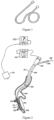
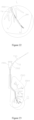
- the coil After being delivered into a bronchus of a pulmonary emphysema region, the coil is released from the restriction of the loading system and then recovers to a natural shape (which is a shape without the external force) as shown in Figure 1 , and at the same time, the emphysema region is squeezed under the pulling action of the nickel-titanium alloy wire, thereby discharging gas in the bronchus and reducing the volume of a lung tissue in the pulmonary emphysema region; and therefore, a relatively healthy lung tissue therearound may exert a physiological function better.
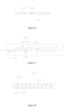
- the delivery sheath 208 is withdrawn, and a gripper 306 of the actuation device 304 is configured to release the coil 301.
- the coil 301 When recovering to an initial shape, the coil 301 also pulls the bronchus 205 to be in curled shape, thereby achieving a pulmonary emphysema volume reduction treatment effect.
- the implant should integrate a channel building process with an implant implantation operation process, make surgical operation more convenient, shorten the surgical operation time and achieve a better treatment effect.
- a lung volume reduction elastic implant is provided as defined in claim 1.
- the implant is tubular and at least opens at the proximal end.
- the implant includes a hollow tubular elastic deformation section, a flexible guide section connected with the distal end of the elastic deformation section, and a protuberance connected with the proximal end of the elastic deformation section.
- the elastic deformation section has a shape memory characteristic and has a plurality of cutout grooves formed in a spacing manner along its lengthwise direction. Each groove is communicated with a lumen of the elastic deformation section. Under the action of a same external force, the flexible guide section deforms more easily than the elastic deformation section, and the outer diameter of the protuberance is larger than that of a portion of the elastic implant, which is close to the protuberance in a delivery state.
- the elastic implant further includes a connection section located between the elastic deformation section and the protuberance. Under action of a same extermanl force, the connection section deforms more easily than the elastic deformation section.
- an included angle between the incision direction of each groove and the lengthwise direction of the elastic deformation section ranges from 10 to 90 degrees.
- the implant further includes an elastic film at least wrapping the outer walls of the elastic deformation section and the flexible guide section.
- the grooves are further filled with the elastic film.
- the elastic deformation section is made of a conical nickel-titanium tube having an outer diameter gradually increased from the distal end to the proximal end, and a gap of 0.05 mm to 0.5 mm is reserved between every two adjacent grooves of the elastic deformation section.
- the flexible guide section includes a main body portion having a spring on the outer wall; the proximal end of the main body portion is connected with the elastic deformation section; and the outer diameter of the main body portion is gradually increased from its distal end to proximal end.
- the flexible guide section includes a tubular body which is cut from the nickel-titanium tube and has continuous spiral grooves.
- a gap between every two adjacent grooves of the flexible guide section along the axial direction of the flexible guide section is gradually increased from the distal end to the proximal end of the flexible guide section.
- connection section has a plurality of grooves formed in a spacing manner along its lengthwise direction, and each groove of the connection section is communicated with the lumen of the connection section.
- the connection section includes multiple hollow subcomponents connected with one another in an end-to-end manner.
- the proximal end of each hollow subcomponent includes multiple proximal end bulges distributed in a circumferential direction of the hollow subcomponent; the circumferential length of each proximal end bulge from the proximal end to the distal end is gradually decreased; a proximal end recess is formed between every two adjacent proximal end bulges; the distal end of each hollow subcomponent includes multiple distal end bulges distributed in the circumferential direction of the hollow subcomponent; the circumferential length of each distal end bulge from the proximal end to the distal end is gradually increased; and a distal end recess is formed between every two adjacent distal end bulges.
- the end surface of part of the distal end of the protuberance is sunken towards the proximal end of the protuberance, thereby forming an annular recess surrounding the longitudinal central line of the protuberance.
- part of the side surface of the protuberance is sunken towards the inside of the protuberance, thereby forming an annular recess surrounding the longitudinal central line of the protuberance.
- the protuberance includes multiple small bulges distributed in the circumferential direction of the protuberance in a spacing manner.
- proximal end an end relatively close to an operator
- distal end an end relatively far away from the operator
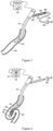
- an elastic implant 500 provided by one embodiment of the present disclosure is of a tubular structure, which includes a hollow tubular elastic deformation section 51, a flexible guide section 53 connected with the distal end of the elastic deformation section 51, a connection section 52 connected with the proximal end of the elastic deformation section 51, a connection member 57 connected with the proximal end of the connection section 52, and an elastic film 55.
- the implant 500 at least opens at the proximal end; the elastic deformation section 51 and the flexible guide section 53 may be of an integrated structure, or are fixedly connected with each other.
- the distal end of the flexible guide section 53 is the distal end of the elastic implant 500.
- the flexible guide section 53 deforms more easily than the elastic deformation section 51 (that is to say, under the action of a same external force, the bending resistance of the flexible guide section 53 is lower than that of the elastic deformation section 51), so that it may move in a bronchus better without injuring a surrounding tissue.
- the elastic deformation section 51 has a shape memory characteristic, and includes a proximal end 511 and a distal end 513 which are opposite; and the distal end 513 is connected with the flexible guide section 53.
- the elastic deformation section 51 further includes multiple grooves 514 which are isolated from one another and are communicated with a lumen of the elastic deformation section 51.
- the multiple grooves 514 enable the elastic deformation section 51 of the elastic implant 500 to be bent into a preset shape in a natural state, for example, a shape as shown in Figure 5 .
- the elastic deformation section 51 In the natural state (namely without any external force), the elastic deformation section 51 is of a preset curled shape, but under the action of an external force, it may be restricted into a straight line form or any other shapes, and would be recovered into the preset shape through bending and twisting if the external force is withdrawn.
- the elastic deformation section 51 may be made of any material which is commonly used in this industry and has a shape memory function. The present disclosure does not limit specific materials, and materials which are applicable to human body and have shape memory function are acceptable.
- the elastic deformation section 51 is made of a nickel-titanium alloy.
- a machining method of an elastic deformation section 51 includes: firstly, cutting a section of hollow nickel-titanium tube having a diameter of about 0.5 to 2.0 mm and a wall thickness of 0.01 to 0.4 mm with laser; then bending the cut nickel-titanium tube with a die into a shape of an elastic deformation section 51 as shown in Figure 5 ; and finally, performing thermal treatment for modeling, thus obtaining the elastic deformation section 51.
- the elastic deformation section 51 may extend into a thinner bronchus to achieve a better squeezing effect on a corresponding tissue
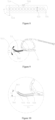
- the elastic deformation section 51 is made of a conical nickel-titanium tube having a consistent inner diameter and a gradually varying wall thickness, for example, a conical nickel-titanium tube having an inner diameter of 0.8 to 1.0 mm and a wall thickness varying from 0.01 mm at the distal end to 0.4 mm at the proximal end; multiple dumbbell-shaped grooves 514 are formed in the nickel-titanium tube, and an extending direction 518 (namely an incision direction) of these grooves 514 and the axial line 501 of the elastic deformation section 51 form a certain angle A which is preferably 10 to 90 degrees.
- a gap 508 of about 0.05 to 0.5 mm is reserved between every two adjacent grooves 514.
- the elastic deformation section 51 has the multiple grooves 514, its bending resistance may vary with changes of the lengths 510 of the grooves 514 along their extending direction 518.
- a person skilled in the art could set the lengths 510 of the grooves 514 of the elastic deformation section 51 in their extending direction 518 according to an actual requirement to achieve an aim that the bending resistance of the flexible guide section 53 is lower than that of the elastic deformation section 51.
- the flexible guide section 53 is disposed at the distal end of the elastic deformation section 51, and is configured to play a guide role for the elastic deformation section 51, and under the action of the same external force, the flexible guide section 53 deforms easily in an increasing manner from the proximal end to the distal end.
- the axial line 503 at the distal end of the flexible guide section 53 and the axial line 502 at the distal end 511 of the elastic deformation section 51 form an included angle B which may be 5 to 60 degrees.
- the flexible guide section 53 includes a main body portion 531, a flexible guide section head end 533 disposed at the distal end of the main body portion 531 and a spring 535 disposed on the outer wall of the main body portion 531.
- the main body portion 531 may support the spring 535, and may be made of a metal with relatively high elasticity, such as a nickel-titanium alloy and a cobalt-chromium alloy, and the outer diameter of the main body portion 531 is gradually increased from the distal end of the main body portion 531 to the proximal end of the main body portion 531.
- the proximal end of the main body portion 531 is connected with the distal end 511 of the elastic deformation section 51 in ways of macromolecular heat-shrink tube or film wrapping, glue adhesion, laser welding, soldering and the like.
- the main body portion 531 is a solid nickel-titanium rod.
- the main body portion 531 also may be a hollow nickel-titanium tube.
- a hollow nickel-titanium tube if the inner diameter of the main body portion 531 does not change from the proximal end to the distal end, its outer diameter is gradually increased from the distal end to the proximal end, and if the outer diameter of the main body portion 531 does not change from the proximal end to the distal end, its inner diameter is gradually decreased from the distal end to the proximal end.
- the distal end of the spring 535 and the distal end of the main body portion 531 are fused together at high temperature, thus forming the flexible guide section head end 533.
- the flexible guide section head end 533 is coaxial with the distal end of the main body portion 531 and closes the distal end of the main body portion 531.
- the flexible guide section head end 533 may further have an imaging label (not shown in the figures).
- the spring 535 is formed by winding a metal wire with a diameter of 0.05 to 0.5 mm (preferably, a tungsten metal wire, a tantalum metal wire and the like with relatively high X-ray developing property).
- a metal wire with a diameter of 0.05 to 0.5 mm preferably, a tungsten metal wire, a tantalum metal wire and the like with relatively high X-ray developing property.
- the flexible guide section head end 533, the spring 535 and the main body portion 531 may be formed separately as well, and then the flexible guide section head end 533, and the distal end of the spring 535 are connected together with the distal end of the main body portion 531 in ways of macromolecular heat-shrink tube or film wrapping, glue adhesion, laser welding and the like; in case of separate forming, preferably, the flexible guide section head end 533 is made of a metal with relatively high X-ray developing property, such as tungsten and tantalum. It further should be understood that the flexible guide section head end
- a closing member made of the same material or a similar material as the guide head 533 may be disposed in the proximal end of the main body portion 531 to fully close or half close the distal end of the elastic deformation section 51; on the other hand, the proximal end of the main body portion 531 may be also communicated with the elastic deformation section 51; and at this moment, the implant 500 opens at both the proximal end and the distal end.
- a core wire (specifically described below) does not penetrate through the distal end of the flexible guide section 53, that is to say, when the implant 500 opens at the distal end, it needs to ensure that the core wire may enter the implant 500 and the outer diameter of the core wire would be larger than that of an incircle of the opening in the distal end of the implant 500 (when the opening is a non-circular opening, such as a triangular opening and a square opening) or larger than that of the opening in the distal end (when the opening is a circular opening).
- connection section 52 is connected between the connection member 57 and the elastic deformation section 51, and under the action of a same external force, the bending resistance of the connection section 52 is lower than that of the elastic deformation section 51 (namely under the action of a same external force, the connection section 52 deforms more easily than the elastic deformation section 51).
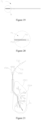
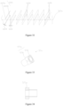
- multiple groove groups 1702 are disposed on the connection section 52.
- each groove group 1702 includes three grooves 1702a, 1702b and 1702c which are arrayed in a circumferential direction of the connection section 52 and are parallel to one another, and two ends of the three grooves are aligned with each other in the circumferential direction. And a certain gap 1703 is reserved between every two adjacent grooves in each groove group 1702, and a gap 1704 is reserved between every two adjacent groove groups 1702.
- Each groove is of a slender structure, and the extending direction AC of the multiple grooves and the axial line 513 of the connection section 52 form a certain included angle C.
- the bending resistance of the whole connection section 52 may be adjusted by adjusting the number of the grooves in each groove group 1702, the sizes of the gaps 1703, the degree size of the included angle C between the extending direction AC of the grooves and the axial line 501 of the elastic deformation section 51 and the size of the gap 1704 between every two adjacent groove groups 1702, so that the bending resistance of the connection section 52 is lower than that of the elastic deformation section 51.
- the gap 1703 between every two adjacent grooves in each groove group 1702 may be 0.05 to 1 mm
- the included angle C may be 10 to 85 degrees
- the gap 208 between every two adjacent groups may be 0.1 to 1.0 mm.
- the outer diameter of the elastic deformation section 51 is about 1.0 to 2.0 mm, and the wall thickness is 0.05 to 0.3 mm.
- Connection between the connection section 52 and the elastic deformation section 51 may be realized in ways of macromolecular heat-shrink tube or film wrapping, glue adhesion, laser welding, soldering and the like. Based on prior arts, an integrated cutting way is preferred that is the elastic deformation section 51 and the connection section 52 which have different texture features are cut from different regions on the same tube material.
- connection member 57 is disposed at the proximal end of the connection section 52, and includes a protuberance 571 and a connection portion 573.
- the outer diameter D of the protuberance 571 is larger than that of a portion, which is close to the protuberance 571, on the elastic implant 500 in a delivery state.
- the outer diameter of the portion, which is close to the protuberance 571, on the elastic implant 500 is the outer diameter of the proximal end of the connection section 52.
- An internal thread 574 is in the protuberance 571.
- connection portion 573 is disposed between the protuberance 571 and the connection section 52, and has a cavity 575 which penetrates through the end surfaces of the proximal end and the distal end of the connection portion 573.
- the cross section, which is parallel to a longitudinal central axis of the protuberance 571, of the protuberance 571 includes two opposite semicircles, and the outer diameter D would not exceed 2.8 mm, preferably 2.0 to 2.3 mm.
- the protuberance 571 effectively enlarges a contact area of the proximal end of the elastic implant 500 and reduce the injury to a lung tissue due to the implantation of the elastic implant 500.
- the elastic implant film 55 completely wraps the outer surface of the elastic implant 500 except for the protuberance 571, and each groove 514 is filled with the film, but the film does not block the lumen of the elastic implant 500, thereby ensuring that the elastic implant film 55 firmly wraps the elastic implant 500 and also ensuring that the lumen of the elastic implant 500 is unblocked.
- the elastic implant film 55 may have a thickness of 0.01 to 0.8 mm, and may be prepared from macromolecular solutions featuring high chemical stability, water resistance and weather aging resistance, good low compressibility, good biocompatibility, high mechanical strength, non-toxicity, odorlessness and the like.
- these macromolecular solutions may be silicone rubber or polyurethane solutions.
- the elastic implant film 55 As the elastic implant film 55 is combined with a metal matrix, the end portion of its proximal end would turn up and fall off most easily under an external force; the outer diameter of the protuberance 571 is larger than that of the portion, which is close to the protuberance 571, on the elastic implant 500 in the delivery state, so that the protuberance 571 may protect the end portion of the proximal end of the elastic implant film 55 from being in contact with a tube wall in delivery and withdrawal processes, thereby protecting the elastic implant film 55 from turning up and falling off in the delivery and withdrawal processes.
- a comparative lung volume reduction device 600 (not part of the invention) includes an elastic implant 500 and a delivery device 700.
- the delivery device 700 includes a core wire 71 and a pushing mechanism 73.
- the core wire 71 is accommodated in a lumen of the elastic implant 500, and is configured to limit the elastic implant 500 in an approximately straight line type delivery state to facilitate delivery of the implant 500 to a lesion portion, thus no delivery sheath is needed to restrict the implant 500, which prevents the delivery sheath from injuring a trachea in a delivery process and further reduces incidence of pneumothorax.
- the core wire 71 may be made of a section of metal wire having a diameter of 0.1 to 1.1 mm. Compared with the prior art, the present disclosure does not need the delivery sheath, so that the implant 500 may be implanted into a lung bypass or the ends of some small-diameter tracheas to achieve a better treatment effect.
- a flexible core wire guide head 75 which is coaxial with the core wire 71 and has an imaging label, at the distal end of the core wire 71.
- the outer diameter of the core wire guide head 75 is consistent with that of the core wire 71.
- the core wire guide head 75 includes a guide post 751 and a spring 753 fixed outside the guide post 751 in a sleeving manner.
- the guide post 751 and the core wire 71 are of an integrated structure or the guide post 751 is fixedly connected to the distal end of the core wire 71; and the spring 753 has an imaging label.
- the core wire guide head 75 is configured to guide the core wire 71 to successfully enter the lumen of the elastic implant 500.
- the flexible core wire guide head 75 may be implemented through a flexible spring, and namely the spring 753 is disposed in a sleeving manner on the guide post 751 which is of an integrated structure with the core wire 71 or is fixedly connected to the distal end of the core wire 71.
- a specific manufacturing method may include: firstly thinning the head end of the core wire 71 to manufacture the guide post 751, and then fixing a section of the spring 753 having a length of 5 to 150 mm outside the guide post 751.
- the spring 753 and the core wire 71 may be fixed in ways of macromolecular heat-shrink tube or film wrapping, glue adhesion, laser welding, soldering and the like. Under the guide of the flexible core wire guide head 75, the core wire 71 may successfully enter the lumen of the implant 500 from the proximal end of the implant 500 to restrict the implant 500 into an approximate straight line form (as shown in Figure 17 ) from the shape as shown in Figure 5 and Figure 9 .
- the implant 500 equipped with a core wire 71 further has a function of exploring a path in the bronchus to reach the lesion region. It needs to dispose the imaging label on the core wire guide head 75 to guide and monitor an operation condition of the core wire 71 in the lung.
- the imaging label can display the implant through a fluorescence inspection system, an ultrasonic imaging system, an MRI (Magnetic Resonance Imaging) system, an X-ray CT (Computerized Tomography) system or other remote imaging systems, and there is no limitation to a specific structure.
- the core wire 101 is developed and guided through these systems.
- the spring formed by winding a metal wire with the wire diameter of 0.01 to 0.3 mm and relatively high X-ray developing property, such as a tungsten metal wire and a tantalum metal wire, is used as an imaging label.
- the imaging label and the core wire guide head 75 are combined into one component to realize two functions. Besides such a mode, an extra developing label may be disposed on the core wire guide head 75.
- the implant of the present disclosure is not wrapped by an elastic film, and the implant is made of a material capable of realizing imaging by itself, such as the nickel-titanium alloy, no imaging label is disposed.
- the pushing mechanism 73 includes a hollow pushing member 731 and a control handle 733 connected with the hollow pushing member 731.
- the hollow pushing member 731 and the implant 500 are disposed on the core wire 71 in a sleeving manner in sequence from outside to inside; and the distal end of the hollow pushing member 731 is detachably connected with the proximal end 511 of the implant 500.
- the hollow pushing member 731 is a pushing steel cable, and a connection matching member 735 having an external thread matched with the internal thread of the connection member 57 is disposed at its distal end.
- connection member 57 is in threaded connection with the connection matching member 735 with the external thread of the pushing mechanism 73, and the implant 500 may be reliably fixed at the distal end of the hollow pushing member 73.
- the connection member 57 of the implant 500 is screwed out of and separated from the connection matching member 735 of the hollow pushing member 73 by twisting the control handle 733 of the hollow pushing member 73.
- the connection member 57 and the connection matching member 735 may be other detachably fixed connection components, such as magnetic connection devices, elastic buckles and ropes, which are disposed on the implant 500 and the hollow pushing member 103 respectively to realize detachable connection.
- Assembling steps of the elastic implant 500 and the core wire 71 as well as the hollow pushing member 731 are as follows: firstly, connecting the elastic implant 500 with the connection matching member 735 at the distal end of the hollow pushing member 731 through the threads to communicate the hollow pushing member 731 with an inner channel of the elastic implant 500; and then pushing the core wire 71 into the elastic implant 500 along a channel of the hollow pushing member 731 to restrict the elastic implant 500, which is curled in a natural state, into a tube in an approximately straight line type delivery state.
- an implant 500 equipped with the core wire 73 and the hollow pushing member 731 is delivered into the bronchus 1504 of a lung 1503 through a working channel 1502 of a bronchoscope 1501. With the assistance of X-rays, the implant 500 is pushed to an expected position by using the hollow pushing member 731, and then the core wire 71 is withdrawn.
- the implant 500 is automatically recovered to the natural shape as shown in Figure 17 from the straight line type delivery state restricted by the core wire 71; and in this recovery process, the pulmonary emphysema region may be squeezed and pulled, and a relatively healthy lung tissue therearound may better exert a respiration physiological function, thereby achieving a lung volume reduction effect.
- the threaded connection between the connection matching member 735 at the distal end of the hollow pushing member 731 and the connection member 57 of the elastic implant 500 is relieved by rotating the handle 733, thereby releasing the implant 500.
- an elastic implant 500a provided by another embodiment of the present disclosure includes a hollow tubular elastic deformation section 51a, a flexible guide section 53a connected with the distal end of the elastic deformation section 51a, a connection section 52a connected with the proximal end of the elastic deformation section 51a, and a connection member 57a connected with the proximal end of the connection section 54a.
- the implant 500a at least opens at the proximal end, and the elastic deformation section 51a and the flexible guide section 53a may be of an integrated structure, or are fixedly connected with each other.
- the distal end of the flexible guide section 53a is the distal end of the elastic implant 500a.
- the flexible guide section 53a deforms more easily than the elastic deformation section 51a (that is to say, under the action of the same external force, the bending resistance of the flexible guide section 53a is lower than that of the elastic deformation section 51a), so that it may move in a bronchus better without injuring a surrounding tissue.
- the elastic deformation section 51a includes multiple groove clusters 1802 which are arrayed in an axial direction of the elastic deformation section 51a in a spacing manner.
- Each groove cluster 1802 consists of five elliptical groove groups 1803 which are disposed side by side and are arrayed in a stair-stepping manner.
- Each groove group 1803 in this embodiment consists of two side-by-side grooves; a certain gap 1801 is reserved between the two grooves in each groove group 1803; and the long axis of each groove is perpendicular to the axial line of the elastic deformation section 51a.
- the extending direction 1805 of arrangement of every two groups in each groove cluster 1802 and the axial line 501a of the elastic deformation section 51a form a certain included angle E which may be 60 to 90 degrees.
- a gap 508a of about 0.3 to 5 mm is reserved between every two adjacent groove groups 1803 in each groove cluster 1802.
- the groove groups 1803 arrayed in the stair-stepping manner contribute to bending the elastic deformation section 51a into a specific shape.
- a portion having a length of about 0.5 to 5 mm at the proximal end 511a of the elastic deformation section 51a is cut into a threaded trench serving as a connection member 57a.
- a cut nickel-titanium tube is bent with a die into a shape as shown in Figure 25 , and then is subjected to thermal treatment modeling, thereby forming the elastic deformation section 51a of an elastic implant 500a.
- connection section 52a is a tubular body which is formed by connecting multiple hollow subcomponents 2004 in an end-to-end manner and has multiple circumferentially continuous wavy grooves 2001.
- the grooves 2001 have certain widths 2005 which may be preferably 0.01 mm to 0.3 mm. Starting points and ending points of every two adjacent wavy grooves 2001 are overlapped in the circumferential direction of the connection section 52a.
- the proximal end of each subcomponent 2004 includes multiple proximal end bulges 2002 distributed in the circumferential direction of the hollow subcomponent 2004 in an equal spacing manner; and the circumferential length of each proximal end bulge 2002 is gradually decreased from the proximal end to the distal end, thus a dovetail-shaped opening towards a proximal end recess 2006 at the proximal end is formed between every two adjacent proximal end bulges 2002; the distal end of each hollow subcomponent 2004 includes multiple distal end bulges 2007 distributed in the circumferential direction of the hollow subcomponent 2004 in an equal spacing manner; and the circumferential length of each distal end bulge 2007 is gradually increased from the proximal end to the distal end, thus a dovetail-shaped opening towards a distal end recess 2008 at the distal end is formed between every two adjacent distal end bulges 2007; the quantity of the proximal end bulges 2002 of each hollow subcomponent 2004
- connection section 52a As all the separated subcomponents 2004 are connected through meshing structures of the dovetail-shaped bulges and the dovetail recesses, the connection section 52a with such structure has extremely high flexibility and connection strength, and may transmit a torque to the elastic deformation section 51a at a ratio of 1 to 1 during twisting of the connection member 57.
- the subcomponents 2004 may be also machined in other ways, such as machining, casting and powder metallurgy.
- connection section 52a has extremely high flexibility and extremely low bending resistance, so that the aim that the bending resistance of the connection section 52a is lower than that of the elastic deformation section 51a may be achieved easily by adjusting the bending resistance of the elastic deformation section 51a.
- the multiple proximal end bulges 2002 may be also distributed at the proximal ends of the subcomponents 2004 in a non-equal spacing manner to achieve the aim that the multiple subcomponents 2004 may be spliced together.
- the bending resistance of the flexible guide section 53a is lower than that of the elastic deformation section 51a, so as to guide the elastic deformation section 51a better to move in the bronchus and reduce injury to the bronchus wall. Under the action of the same external force, the bending resistance of the flexible guide section 53a is gradually enhanced from the distal end to the proximal end.
- the flexible guide section 53a is a tubular body, which is cut from a nickel-titanium tube through laser and has grooves, and under the action of the same external force, its bending resistance is gradually enhanced from the distal end to the proximal end (that is to say, under the action of the same external force, its deformability is gradually lowered from the distal end to the proximal end, and namely it becomes harder and harder from the distal end to the proximal end), so as to achieve a better guide effect on the elastic implant 500a.
- the flexible guide section 53a is the tubular body having the multiple grooves, its bending resistance may change with the change of a gap between every two adjacent grooves.
- a person skilled in the art could set the gap between every two adjacent grooves according to an actual requirement to achieve an aim that the bending resistance of the flexible guide section 53a is lower than that of the elastic deformation section 51a.
- the flexible guide section 53a includes multiple slender groove groups from 1601 to 1608.
- Each groove group (for example 1601) consists of two or more parallel grooves 1601a and 1601b, and each parallel groove has a certain width 1609.
- the extending direction of these groove groups from 1601 to 1608 and the axial line 513a of the flexible guide section 53a form a certain angle F.
- a gap 1610 is reserved between every two adjacent groove groups.
- the bending resistance of the flexible guide section 53a may be adjusted by adjusting the number and the widths 1609 of the grooves in each groove group, the degree size of the angle F and the sizes of the gaps 1610.
- the gaps 1609 are 0.05 to 1 mm, the angle F is 5 to 85 degrees, and the gaps 1610 is 0.1 to 1.0 mm.
- the parallel groove groups (from 1601 to 1608) with different widths 1609 are combined into a same nickel-titanium tube, thereby achieving the aim that under the action of the same external force, the bending resistance of the flexible guide section 53a is gradually enhanced from the distal end to the proximal end; and the flexible guide section 53a with a bending resistance gradual change effect may achieve a better guide effect on the elastic implant 500a.
- the flexible guide section 53a and the elastic deformation section 51a may be connected in ways of macromolecular heat-shrink tube or film wrapping, glue adhesion, laser welding, soldering and the like. Based on the prior art, an integrated cutting way is preferred: cutting the flexible guide section 53a and the elastic deformation section 51a which have different texture features from different regions on the same tube material.
- one feasible mode is to keep the angle F between every two adjacent groove groups unchanged and gradually decrease the widths 1609 of the grooves from the distal end to the proximal end
- another feasible mode is to keep the widths 1609 of the grooves in every two adjacent groove groups unchanged and gradually enlarge the angle F. It should be understood that the effect of gradually enhancing the bending resistance of the flexible guide section 53a from the distal end to the proximal end also may be achieved by simultaneously changing the angle F and the widths 1609 of the grooves in every two adjacent groove groups.
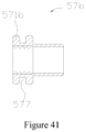
- connection member 57a is substantially the same as the connection body 57, but what is different is that a protuberance 571a of the connection member 57a has multiple small bulges 578 which are distributed in the circumferential direction of the protuberance 571a in an equal spacing manner and are connected with one another.
- the multiple small bulges 578 form a virtual circumference 579 together (namely an circumcircle of the multiple small bulges 578 is 579).
- the diameter of the circumference 579 is the outer diameter of the protuberance 571a.
- the multiple small bulges 578 provide a buckling position for biopsy forceps, so that the biopsy forceps may effectively clamp the connection device to recycle the elastic implant 500a.
- the connection member 57a and the connection section 52a may be connected in ways of macromolecular heat-shrink tube or film wrapping, glue adhesion, laser welding, soldering and the like.
- an elastic implant 500b provided by another embodiment of the present disclosure includes a hollow tubular elastic deformation section 51b, a flexible guide section 53b connected with the distal end of the elastic deformation section 51b, a connection section 52b connected with the proximal end of the elastic deformation section 51b, and a connection member 57b connected with the proximal end of the connection section 52b.
- the implant 500b at least opens at the proximal end; the elastic deformation section 51b and the flexible guide section 53b may be of an integrated structure, or are fixedly connected with each other.
- the distal end of the flexible guide section 53b is the distal end of the elastic implant 500b. Under the action of a same external force, the flexible guide section 53b deforms more easily than the elastic deformation section 51b, so that it may move in a bronchus better without injuring a surrounding tissue.
- the arrangement mode of grooves of the elastic deformation section 51b is substantially the same as that of the grooves of the connection section 52 of the embodiment I, and no repeated descriptions will be given here.
- the flexible guide section 53b is a tubular body which is cut from a nickel-titanium tube through laser and has continuous spiral grooves, and under the action of the same external force, its bending resistance is gradually enhanced from the distal end to the proximal end (that is to say, under the action of the same external force, its deformability is gradually lowered from the distal end to the proximal end) to achieve a better guide effect on the elastic implant 500b.
- the flexible guide section 53b is a tubular body having continuous spiral grooves, its bending resistance may change with the change of a gap between every two adjacent grooves. A person skilled in the art could set the gap between every two adjacent grooves according to an actual requirement to achieve an aim that the bending resistance of the flexible guide section 53b is lower than that of the elastic deformation section 51b.
- the flexible guide section 53b includes the continuous spiral grooves 2502. On an unfolded plane formed by splitting the flexible guide section 53b along its axial direction, from the distal end to the proximal end of the flexible guide section 53b, the gap between every two adjacent grooves 2502 is gradually increased as well to achieve the aim of gradually enhancing the bending resistance of the flexible guide section 53b from the distal end to the proximal end.
- connection section 52b is substantially the same as that of the connection section 52a, and no repeated descriptions will be given here.
- an integrated forming way is adopted.
- Features of the elastic deformation section 51b, the flexible guide section 53b and the connection section 52b which are cut from the same nickel-titanium tube through laser are as shown in Figure 39 , and problems of low connection strength and the like which are caused by a connection mode may be effectively avoided.
- connection member 57b is substantially the same as the connection member 57, but what is different is that part of the side surface of the protuberance 571b of the connection member 57b is sunken towards the inside of the protuberance 571b, thereby forming an annular recess 577 surrounding the longitudinal central line of the protuberance 571b.
Landscapes
- Health & Medical Sciences (AREA)
- Surgery (AREA)
- Life Sciences & Earth Sciences (AREA)
- Heart & Thoracic Surgery (AREA)
- Molecular Biology (AREA)
- Veterinary Medicine (AREA)
- Engineering & Computer Science (AREA)
- Biomedical Technology (AREA)
- Nuclear Medicine, Radiotherapy & Molecular Imaging (AREA)
- Medical Informatics (AREA)
- Public Health (AREA)
- Animal Behavior & Ethology (AREA)
- General Health & Medical Sciences (AREA)
- Reproductive Health (AREA)
- Vascular Medicine (AREA)
- Pathology (AREA)
- Oral & Maxillofacial Surgery (AREA)
- Prostheses (AREA)
- Media Introduction/Drainage Providing Device (AREA)
Claims (11)
- Elastisches Lungenvolumenreduktionsimplantat, wobei das Implantat röhrenförmig ist, sich wenigstens an seinem proximalen Ende öffnet und einen hohlen, röhrenförmigen, elastischen Verformungsabschnitt (51), einen flexiblen Führungsabschnitt (53), der mit dem distalen Ende des elastischen Verformungsabschnitts (51) verbunden ist, und einen Vorsprung (571) umfasst, der mit dem proximalen Ende des elastischen Verformungsabschnitts (51) verbunden ist, und der elastische Verformungsabschnitt (51) eine Formgedächtniseigenschaft hat und mehrere Nuten (514) aufweist, die voneinander beabstandet entlang einer Längsrichtung des elastischen Verformungsabschnitts (51) gebildet sind, und jede Nut mit einem Lumen des elastischen Verformungsabschnitts (51) in Verbindung steht, und wobei sich der flexible Führungsabschnitt (53) unter der Wirkung einer gleichen äußeren Kraft leichter verformt als der elastische Verformungsabschnitt (51),wobei sich der flexible Führungsabschnitt (53) unter der Wirkung der gleichen äußeren Kraft vom proximalen Ende zum distalen Ende zunehmend leichter verformt,ein Verbindungsabschnitt (52) sich zwischen dem elastischen Verformungsabschnitt (51) und dem Vorsprung (571) befindet und wobei sich der Verbindungsabschnitt (52) unter der Wirkung einer gleichen äußeren Kraft leichter verformt als der elastische Verformungsabschnitt (51), undwobei der Außendurchmesser des Vorsprungs (571) größer als der eines Teils des elastischen Implantats ist, der in einem Abgabezustand nahe dem Vorsprung liegt.
- Elastisches Lungenvolumenreduktionsimplantat nach Anspruch 1, dadurch gekennzeichnet, dass ein eingeschlossener Winkel zwischen der Einschnittrichtung jeder Nut (514) und der Längsrichtung des elastischen Verformungsabschnitts (51) im Bereich von 10 bis 90 Grad liegt.
- Elastisches Lungenvolumenreduktionsimplantat nach Anspruch 2, dadurch gekennzeichnet, dass es ferner eine elastische Folie (55) umfasst, die wenigstens die Außenwände des elastischen Verformungsabschnitts (51) und des flexiblen Führungsabschnitts (53) umhüllt.
- Elastisches Lungenvolumenreduktionsimplantat nach Anspruch 3, dadurch gekennzeichnet, dass die Nuten (514) ferner mit der elastischen Folie gefüllt sind.
- Elastisches Lungenvolumenreduktionsimplantat nach Anspruch 2, dadurch gekennzeichnet, dass der elastische Verformungsabschnitt (51) aus einem konischen Nickel-Titan-Rohr gebildet ist, das einen Außendurchmesser aufweist, der vom distalen Ende zum proximalen Ende allmählich zunimmt, und zwischen jeweils zwei benachbarten Nuten (514) des elastischen Verformungsabschnitts (51) ein Spalt von 0,05 mm bis 0,5 mm vorgesehen ist.
- Elastisches Lungenvolumenreduktionsimplantat nach Anspruch 1, dadurch gekennzeichnet, dass der flexible Führungsabschnitt (53) einen Hauptkörperteil mit einer Feder an der Außenwand umfasst, wobei das proximale Ende des Hauptkörperteils mit dem elastischen Verformungsabschnitt (51) verbunden ist und der Außendurchmesser des Hauptkörperteils vom distalen Ende zum proximalen Ende allmählich zunimmt.
- Elastisches Lungenvolumenreduktionsimplantat nach Anspruch 1, dadurch gekennzeichnet, dass der flexible Führungsabschnitt (53) einen röhrenförmigen Körper umfasst, der aus einem Nickel-Titan-Rohr geschnitten ist und durchgehende Spiralnuten (2502) aufweist.
- Elastisches Lungenvolumenreduktionsimplantat nach Anspruch 6, dadurch gekennzeichnet, dass der Spalt zwischen jeweils zwei benachbarten Nuten des flexiblen Führungsabschnitts (53) entlang der Axialrichtung des flexiblen Führungsabschnitts (53) vom distalen Ende zum proximalen Ende des flexiblen Führungsabschnitts (53) allmählich größer wird.
- Elastisches Lungenvolumenreduktionsimplantat nach Anspruch 1, dadurch gekennzeichnet, dass eine Endfläche eines Teils des distalen Endes des Vorsprungs (571) zum proximalen Ende des Vorsprungs (571) hin vertieft ist, wodurch eine ringförmige Ausnehmung gebildet ist, die die Längsmittellinie des Vorsprungs (571) umgibt.
- Elastisches Lungenvolumenreduktionsimplantat nach Anspruch 1, dadurch gekennzeichnet, dass ein Teil der Seitenfläche des Vorsprungs (571) zum Inneren des Vorsprungs (571) hin vertieft ist, wodurch eine ringförmige Ausnehmung gebildet ist, die die Längsmittellinie des Vorsprungs (571) umgibt.
- Elastisches Lungenvolumenreduktionsimplantat nach Anspruch 1, dadurch gekennzeichnet, dass der Vorsprung (571) mehrere kleine Ausbuchtungen (578) umfasst, die um die Umfangsrichtung des Vorsprungs (571) voneinander beabstandet verteilt sind.
Applications Claiming Priority (2)
| Application Number | Priority Date | Filing Date | Title |
|---|---|---|---|
| CN201510785463.8A CN106691626B (zh) | 2015-11-16 | 2015-11-16 | 肺减容弹性植入体及肺减容器械 |
| PCT/CN2016/087790 WO2017084347A1 (zh) | 2015-11-16 | 2016-06-29 | 肺减容弹性植入体及肺减容器械 |
Publications (3)
| Publication Number | Publication Date |
|---|---|
| EP3378447A1 EP3378447A1 (de) | 2018-09-26 |
| EP3378447A4 EP3378447A4 (de) | 2019-07-31 |
| EP3378447B1 true EP3378447B1 (de) | 2025-03-12 |
Family
ID=58717359
Family Applications (1)
| Application Number | Title | Priority Date | Filing Date |
|---|---|---|---|
| EP16865527.2A Active EP3378447B1 (de) | 2015-11-16 | 2016-06-29 | Elastisches implantat zur lungenvolumenreduktion und lungenvolumenreduktionsvorrichtung |
Country Status (5)
| Country | Link |
|---|---|
| US (1) | US10687821B2 (de) |
| EP (1) | EP3378447B1 (de) |
| CN (1) | CN106691626B (de) |
| ES (1) | ES3025735T3 (de) |
| WO (1) | WO2017084347A1 (de) |
Families Citing this family (11)
| Publication number | Priority date | Publication date | Assignee | Title |
|---|---|---|---|---|
| CN108272538B (zh) * | 2016-12-30 | 2020-06-12 | 先健科技(深圳)有限公司 | 肺减容弹性植入体及肺减容器械 |
| US11172933B2 (en) * | 2017-08-29 | 2021-11-16 | Covidien Lp | Methods and devices for altering lung volume |
| CN109965923B (zh) * | 2017-12-28 | 2021-07-06 | 深圳市先健呼吸科技有限公司 | 用于具有至少一个空腔的植入体的输送器 |
| CN109966011B (zh) * | 2017-12-28 | 2021-08-17 | 深圳市先健呼吸科技有限公司 | 用于具有至少一个空腔的植入体的输送及回收装置和系统 |
| CN109984876B (zh) * | 2017-12-29 | 2021-10-22 | 深圳市先健呼吸科技有限公司 | 用于肺减容植入体的回收系统和鞘管 |
| CN110638488B (zh) * | 2018-06-26 | 2025-08-15 | 杭州唯强医疗科技有限公司 | 连接可靠的植入物推送装置及植入物输送系统 |
| CN110638490B (zh) * | 2018-06-26 | 2025-08-15 | 杭州唯强医疗科技有限公司 | 可锁定的植入物推送装置及植入物输送系统 |
| CN113107938B (zh) * | 2021-04-02 | 2022-05-06 | 桂林理工大学 | 一种可弯曲套筒及可伸缩结构 |
| CN118476900A (zh) * | 2024-04-03 | 2024-08-13 | 七星蓝(深圳)科技有限公司 | 植入体、输送机构、肺减容植入装置及系统 |
| CN118203400B (zh) * | 2024-05-20 | 2024-08-02 | 四川大学华西医院 | 一种牵拉复位装置 |
| CN120732489A (zh) * | 2025-09-04 | 2025-10-03 | 北京大学 | 一种可调的医疗器械装置 |
Citations (3)
| Publication number | Priority date | Publication date | Assignee | Title |
|---|---|---|---|---|
| EP0957845B1 (de) * | 1995-06-07 | 2003-09-17 | Conceptus, Inc. | Transcervikale verhütungsvorrichtung zum eileiterverschliessen mit mechanischer befestigung am eileiter |
| WO2014151557A2 (en) * | 2013-03-15 | 2014-09-25 | Pneumrx, Inc. | Torque alleviating intra-airway lung volume reduction compressive implant structures |
| EP3169250B1 (de) * | 2014-07-18 | 2019-08-28 | Ethicon, Inc. | Vorrichtung zum einstellen der grösse von bullösem emphysem |
Family Cites Families (10)
| Publication number | Priority date | Publication date | Assignee | Title |
|---|---|---|---|---|
| US8157837B2 (en) * | 2006-03-13 | 2012-04-17 | Pneumrx, Inc. | Minimally invasive lung volume reduction device and method |
| US9402633B2 (en) * | 2006-03-13 | 2016-08-02 | Pneumrx, Inc. | Torque alleviating intra-airway lung volume reduction compressive implant structures |
| US8721734B2 (en) * | 2009-05-18 | 2014-05-13 | Pneumrx, Inc. | Cross-sectional modification during deployment of an elongate lung volume reduction device |
| US8632605B2 (en) * | 2008-09-12 | 2014-01-21 | Pneumrx, Inc. | Elongated lung volume reduction devices, methods, and systems |
| US20140358140A1 (en) * | 2008-10-21 | 2014-12-04 | Microcube, Llc | Microwave treatment devices and methods |
| US11291503B2 (en) * | 2008-10-21 | 2022-04-05 | Microcube, Llc | Microwave treatment devices and methods |
| CN202010169U (zh) * | 2011-03-31 | 2011-10-19 | 王涛 | 新型肺减容记忆弹性线圈 |
| CN103860299A (zh) * | 2012-12-14 | 2014-06-18 | 常州乐奥医疗科技有限公司 | 解剖型肺减容弹性支架 |
| CN105455930B (zh) * | 2014-06-11 | 2019-08-16 | 先健科技(深圳)有限公司 | 肺减容弹性植入体及器械 |
| CN106580527B (zh) * | 2015-10-15 | 2019-02-12 | 先健科技(深圳)有限公司 | 肺减容弹性植入体及肺减容器械 |
-
2015
- 2015-11-16 CN CN201510785463.8A patent/CN106691626B/zh active Active
-
2016
- 2016-06-29 ES ES16865527T patent/ES3025735T3/es active Active
- 2016-06-29 EP EP16865527.2A patent/EP3378447B1/de active Active
- 2016-06-29 WO PCT/CN2016/087790 patent/WO2017084347A1/zh not_active Ceased
- 2016-06-29 US US15/776,050 patent/US10687821B2/en active Active
Patent Citations (3)
| Publication number | Priority date | Publication date | Assignee | Title |
|---|---|---|---|---|
| EP0957845B1 (de) * | 1995-06-07 | 2003-09-17 | Conceptus, Inc. | Transcervikale verhütungsvorrichtung zum eileiterverschliessen mit mechanischer befestigung am eileiter |
| WO2014151557A2 (en) * | 2013-03-15 | 2014-09-25 | Pneumrx, Inc. | Torque alleviating intra-airway lung volume reduction compressive implant structures |
| EP3169250B1 (de) * | 2014-07-18 | 2019-08-28 | Ethicon, Inc. | Vorrichtung zum einstellen der grösse von bullösem emphysem |
Also Published As
| Publication number | Publication date |
|---|---|
| CN106691626A (zh) | 2017-05-24 |
| WO2017084347A1 (zh) | 2017-05-26 |
| CN106691626B (zh) | 2019-03-08 |
| US20180333157A1 (en) | 2018-11-22 |
| EP3378447A4 (de) | 2019-07-31 |
| ES3025735T3 (en) | 2025-06-09 |
| EP3378447A1 (de) | 2018-09-26 |
| US10687821B2 (en) | 2020-06-23 |
Similar Documents
| Publication | Publication Date | Title |
|---|---|---|
| EP3378447B1 (de) | Elastisches implantat zur lungenvolumenreduktion und lungenvolumenreduktionsvorrichtung | |
| CN105455930B (zh) | 肺减容弹性植入体及器械 | |
| EP3363408B1 (de) | Elastisches lungenvolumenreduktionsimplantat und lungenvolumenreduktionsinstrument | |
| CN102573700B (zh) | 细长的肺减容装置在部署过程中的横截面变化 | |
| AU2014233907B2 (en) | Torque alleviating intra-airway lung volume reduction compressive implant structures | |
| EP3563801B1 (de) | Elastisches lungenvolumenreduktionsimplantat und lungenvolumenreduktionsinstrument | |
| US11291457B2 (en) | Lung volume-reducing elastic implant and instrument | |
| EP3556325B1 (de) | Implantat | |
| KR20190059921A (ko) | 가이드와이어 | |
| CN110742667B (zh) | 运用可植入瓣膜治疗肺功能障碍的方法和装置 | |
| CN118476900A (zh) | 植入体、输送机构、肺减容植入装置及系统 | |
| WO2019140179A1 (en) | Methods and devices for the treatment of pulmonary disorders |
Legal Events
| Date | Code | Title | Description |
|---|---|---|---|
| STAA | Information on the status of an ep patent application or granted ep patent |
Free format text: STATUS: THE INTERNATIONAL PUBLICATION HAS BEEN MADE |
|
| PUAI | Public reference made under article 153(3) epc to a published international application that has entered the european phase |
Free format text: ORIGINAL CODE: 0009012 |
|
| STAA | Information on the status of an ep patent application or granted ep patent |
Free format text: STATUS: REQUEST FOR EXAMINATION WAS MADE |
|
| 17P | Request for examination filed |
Effective date: 20180611 |
|
| AK | Designated contracting states |
Kind code of ref document: A1 Designated state(s): AL AT BE BG CH CY CZ DE DK EE ES FI FR GB GR HR HU IE IS IT LI LT LU LV MC MK MT NL NO PL PT RO RS SE SI SK SM TR |
|
| AX | Request for extension of the european patent |
Extension state: BA ME |
|
| DAV | Request for validation of the european patent (deleted) | ||
| DAX | Request for extension of the european patent (deleted) | ||
| A4 | Supplementary search report drawn up and despatched |
Effective date: 20190702 |
|
| RIC1 | Information provided on ipc code assigned before grant |
Ipc: A61F 2/04 20130101ALI20190626BHEP Ipc: A61F 2/95 20130101ALI20190626BHEP Ipc: A61B 17/12 20060101ALI20190626BHEP Ipc: A61F 2/82 20130101AFI20190626BHEP |
|
| STAA | Information on the status of an ep patent application or granted ep patent |
Free format text: STATUS: EXAMINATION IS IN PROGRESS |
|
| 17Q | First examination report despatched |
Effective date: 20200702 |
|
| RAP1 | Party data changed (applicant data changed or rights of an application transferred) |
Owner name: SHENZHEN LIFETECH RESPIRATION SCIENTIFIC CO., LTD. |
|
| GRAP | Despatch of communication of intention to grant a patent |
Free format text: ORIGINAL CODE: EPIDOSNIGR1 |
|
| STAA | Information on the status of an ep patent application or granted ep patent |
Free format text: STATUS: GRANT OF PATENT IS INTENDED |
|
| INTG | Intention to grant announced |
Effective date: 20241017 |
|
| P01 | Opt-out of the competence of the unified patent court (upc) registered |
Free format text: CASE NUMBER: APP_61957/2024 Effective date: 20241120 |
|
| GRAS | Grant fee paid |
Free format text: ORIGINAL CODE: EPIDOSNIGR3 |
|
| GRAA | (expected) grant |
Free format text: ORIGINAL CODE: 0009210 |
|
| STAA | Information on the status of an ep patent application or granted ep patent |
Free format text: STATUS: THE PATENT HAS BEEN GRANTED |
|
| AK | Designated contracting states |
Kind code of ref document: B1 Designated state(s): AL AT BE BG CH CY CZ DE DK EE ES FI FR GB GR HR HU IE IS IT LI LT LU LV MC MK MT NL NO PL PT RO RS SE SI SK SM TR |
|
| REG | Reference to a national code |
Ref country code: GB Ref legal event code: FG4D |
|
| REG | Reference to a national code |
Ref country code: CH Ref legal event code: EP |
|
| REG | Reference to a national code |
Ref country code: DE Ref legal event code: R096 Ref document number: 602016091553 Country of ref document: DE |
|
| REG | Reference to a national code |
Ref country code: IE Ref legal event code: FG4D |
|
| REG | Reference to a national code |
Ref country code: ES Ref legal event code: FG2A Ref document number: 3025735 Country of ref document: ES Kind code of ref document: T3 Effective date: 20250609 |
|
| PG25 | Lapsed in a contracting state [announced via postgrant information from national office to epo] |
Ref country code: RS Free format text: LAPSE BECAUSE OF FAILURE TO SUBMIT A TRANSLATION OF THE DESCRIPTION OR TO PAY THE FEE WITHIN THE PRESCRIBED TIME-LIMIT Effective date: 20250612 |
|
| PG25 | Lapsed in a contracting state [announced via postgrant information from national office to epo] |
Ref country code: FI Free format text: LAPSE BECAUSE OF FAILURE TO SUBMIT A TRANSLATION OF THE DESCRIPTION OR TO PAY THE FEE WITHIN THE PRESCRIBED TIME-LIMIT Effective date: 20250312 |
|
| PGFP | Annual fee paid to national office [announced via postgrant information from national office to epo] |
Ref country code: DE Payment date: 20250603 Year of fee payment: 10 |
|
| REG | Reference to a national code |
Ref country code: LT Ref legal event code: MG9D |
|
| PG25 | Lapsed in a contracting state [announced via postgrant information from national office to epo] |
Ref country code: NO Free format text: LAPSE BECAUSE OF FAILURE TO SUBMIT A TRANSLATION OF THE DESCRIPTION OR TO PAY THE FEE WITHIN THE PRESCRIBED TIME-LIMIT Effective date: 20250612 |
|
| PG25 | Lapsed in a contracting state [announced via postgrant information from national office to epo] |
Ref country code: HR Free format text: LAPSE BECAUSE OF FAILURE TO SUBMIT A TRANSLATION OF THE DESCRIPTION OR TO PAY THE FEE WITHIN THE PRESCRIBED TIME-LIMIT Effective date: 20250312 |
|
| REG | Reference to a national code |
Ref country code: NL Ref legal event code: MP Effective date: 20250312 |
|
| PG25 | Lapsed in a contracting state [announced via postgrant information from national office to epo] |
Ref country code: LV Free format text: LAPSE BECAUSE OF FAILURE TO SUBMIT A TRANSLATION OF THE DESCRIPTION OR TO PAY THE FEE WITHIN THE PRESCRIBED TIME-LIMIT Effective date: 20250312 |
|
| PG25 | Lapsed in a contracting state [announced via postgrant information from national office to epo] |
Ref country code: GR Free format text: LAPSE BECAUSE OF FAILURE TO SUBMIT A TRANSLATION OF THE DESCRIPTION OR TO PAY THE FEE WITHIN THE PRESCRIBED TIME-LIMIT Effective date: 20250613 Ref country code: BG Free format text: LAPSE BECAUSE OF FAILURE TO SUBMIT A TRANSLATION OF THE DESCRIPTION OR TO PAY THE FEE WITHIN THE PRESCRIBED TIME-LIMIT Effective date: 20250312 |
|
| REG | Reference to a national code |
Ref country code: AT Ref legal event code: MK05 Ref document number: 1774408 Country of ref document: AT Kind code of ref document: T Effective date: 20250312 |
|
| PG25 | Lapsed in a contracting state [announced via postgrant information from national office to epo] |
Ref country code: NL Free format text: LAPSE BECAUSE OF FAILURE TO SUBMIT A TRANSLATION OF THE DESCRIPTION OR TO PAY THE FEE WITHIN THE PRESCRIBED TIME-LIMIT Effective date: 20250312 |
|
| PG25 | Lapsed in a contracting state [announced via postgrant information from national office to epo] |
Ref country code: SE Free format text: LAPSE BECAUSE OF FAILURE TO SUBMIT A TRANSLATION OF THE DESCRIPTION OR TO PAY THE FEE WITHIN THE PRESCRIBED TIME-LIMIT Effective date: 20250312 |
|
| PG25 | Lapsed in a contracting state [announced via postgrant information from national office to epo] |
Ref country code: SM Free format text: LAPSE BECAUSE OF FAILURE TO SUBMIT A TRANSLATION OF THE DESCRIPTION OR TO PAY THE FEE WITHIN THE PRESCRIBED TIME-LIMIT Effective date: 20250312 |
|
| PG25 | Lapsed in a contracting state [announced via postgrant information from national office to epo] |
Ref country code: PT Free format text: LAPSE BECAUSE OF FAILURE TO SUBMIT A TRANSLATION OF THE DESCRIPTION OR TO PAY THE FEE WITHIN THE PRESCRIBED TIME-LIMIT Effective date: 20250714 |
|
| PGFP | Annual fee paid to national office [announced via postgrant information from national office to epo] |
Ref country code: ES Payment date: 20250728 Year of fee payment: 10 |
|
| PG25 | Lapsed in a contracting state [announced via postgrant information from national office to epo] |
Ref country code: PL Free format text: LAPSE BECAUSE OF FAILURE TO SUBMIT A TRANSLATION OF THE DESCRIPTION OR TO PAY THE FEE WITHIN THE PRESCRIBED TIME-LIMIT Effective date: 20250312 |
|
| PGFP | Annual fee paid to national office [announced via postgrant information from national office to epo] |
Ref country code: IT Payment date: 20250627 Year of fee payment: 10 |
|
| PG25 | Lapsed in a contracting state [announced via postgrant information from national office to epo] |
Ref country code: AT Free format text: LAPSE BECAUSE OF FAILURE TO SUBMIT A TRANSLATION OF THE DESCRIPTION OR TO PAY THE FEE WITHIN THE PRESCRIBED TIME-LIMIT Effective date: 20250312 |
|
| PG25 | Lapsed in a contracting state [announced via postgrant information from national office to epo] |
Ref country code: CZ Free format text: LAPSE BECAUSE OF FAILURE TO SUBMIT A TRANSLATION OF THE DESCRIPTION OR TO PAY THE FEE WITHIN THE PRESCRIBED TIME-LIMIT Effective date: 20250312 Ref country code: EE Free format text: LAPSE BECAUSE OF FAILURE TO SUBMIT A TRANSLATION OF THE DESCRIPTION OR TO PAY THE FEE WITHIN THE PRESCRIBED TIME-LIMIT Effective date: 20250312 |
|
| PG25 | Lapsed in a contracting state [announced via postgrant information from national office to epo] |
Ref country code: RO Free format text: LAPSE BECAUSE OF FAILURE TO SUBMIT A TRANSLATION OF THE DESCRIPTION OR TO PAY THE FEE WITHIN THE PRESCRIBED TIME-LIMIT Effective date: 20250312 |
|
| PG25 | Lapsed in a contracting state [announced via postgrant information from national office to epo] |
Ref country code: SK Free format text: LAPSE BECAUSE OF FAILURE TO SUBMIT A TRANSLATION OF THE DESCRIPTION OR TO PAY THE FEE WITHIN THE PRESCRIBED TIME-LIMIT Effective date: 20250312 |
|
| PG25 | Lapsed in a contracting state [announced via postgrant information from national office to epo] |
Ref country code: IS Free format text: LAPSE BECAUSE OF FAILURE TO SUBMIT A TRANSLATION OF THE DESCRIPTION OR TO PAY THE FEE WITHIN THE PRESCRIBED TIME-LIMIT Effective date: 20250712 |