EP3378381A1 - Détermination du débit sanguin intravasculaire basée sur la formation de vortex - Google Patents
Détermination du débit sanguin intravasculaire basée sur la formation de vortex Download PDFInfo
- Publication number
- EP3378381A1 EP3378381A1 EP17162723.5A EP17162723A EP3378381A1 EP 3378381 A1 EP3378381 A1 EP 3378381A1 EP 17162723 A EP17162723 A EP 17162723A EP 3378381 A1 EP3378381 A1 EP 3378381A1
- Authority
- EP
- European Patent Office
- Prior art keywords
- blood flow
- vibration sensor
- intravascular
- signal
- vortex
- Prior art date
- Legal status (The legal status is an assumption and is not a legal conclusion. Google has not performed a legal analysis and makes no representation as to the accuracy of the status listed.)
- Withdrawn
Links
- 230000017531 blood circulation Effects 0.000 title claims abstract description 323
- 230000010355 oscillation Effects 0.000 claims abstract description 137
- 238000012545 processing Methods 0.000 claims abstract description 81
- 210000004204 blood vessel Anatomy 0.000 claims abstract description 41
- 238000000034 method Methods 0.000 claims description 26
- 238000004891 communication Methods 0.000 claims description 23
- 210000003495 flagella Anatomy 0.000 claims description 19
- 230000001902 propagating effect Effects 0.000 claims description 13
- 238000003780 insertion Methods 0.000 claims description 11
- 230000037431 insertion Effects 0.000 claims description 11
- 230000004888 barrier function Effects 0.000 claims description 9
- 239000000835 fiber Substances 0.000 claims description 8
- 230000009466 transformation Effects 0.000 claims description 7
- 230000008878 coupling Effects 0.000 claims description 4
- 238000010168 coupling process Methods 0.000 claims description 4
- 238000005859 coupling reaction Methods 0.000 claims description 4
- 230000001121 heart beat frequency Effects 0.000 claims description 4
- 239000013307 optical fiber Substances 0.000 claims description 4
- 239000002861 polymer material Substances 0.000 claims description 4
- 238000005259 measurement Methods 0.000 description 13
- 239000008280 blood Substances 0.000 description 8
- 210000004369 blood Anatomy 0.000 description 8
- 230000033001 locomotion Effects 0.000 description 7
- 206010020565 Hyperaemia Diseases 0.000 description 6
- 239000012530 fluid Substances 0.000 description 5
- 208000031481 Pathologic Constriction Diseases 0.000 description 4
- 238000005452 bending Methods 0.000 description 4
- 238000004590 computer program Methods 0.000 description 4
- 238000010586 diagram Methods 0.000 description 4
- 230000036262 stenosis Effects 0.000 description 4
- 208000037804 stenosis Diseases 0.000 description 4
- 230000005540 biological transmission Effects 0.000 description 3
- 230000015572 biosynthetic process Effects 0.000 description 3
- 230000036772 blood pressure Effects 0.000 description 3
- 238000012512 characterization method Methods 0.000 description 3
- 230000004044 response Effects 0.000 description 3
- 238000003860 storage Methods 0.000 description 3
- 230000001419 dependent effect Effects 0.000 description 2
- 238000011156 evaluation Methods 0.000 description 2
- 230000000544 hyperemic effect Effects 0.000 description 2
- 238000003384 imaging method Methods 0.000 description 2
- 238000002608 intravascular ultrasound Methods 0.000 description 2
- 230000035790 physiological processes and functions Effects 0.000 description 2
- 230000000284 resting effect Effects 0.000 description 2
- 238000012935 Averaging Methods 0.000 description 1
- 230000001133 acceleration Effects 0.000 description 1
- 230000004075 alteration Effects 0.000 description 1
- 230000002238 attenuated effect Effects 0.000 description 1
- 238000004364 calculation method Methods 0.000 description 1
- 210000004351 coronary vessel Anatomy 0.000 description 1
- 238000001514 detection method Methods 0.000 description 1
- 230000000694 effects Effects 0.000 description 1
- 238000001914 filtration Methods 0.000 description 1
- 230000000004 hemodynamic effect Effects 0.000 description 1
- 238000011065 in-situ storage Methods 0.000 description 1
- 230000007246 mechanism Effects 0.000 description 1
- 230000004089 microcirculation Effects 0.000 description 1
- 230000003287 optical effect Effects 0.000 description 1
- 230000005693 optoelectronics Effects 0.000 description 1
- 230000003534 oscillatory effect Effects 0.000 description 1
- 230000000737 periodic effect Effects 0.000 description 1
- 238000005070 sampling Methods 0.000 description 1
- 230000001960 triggered effect Effects 0.000 description 1
- 238000011144 upstream manufacturing Methods 0.000 description 1
- 230000002792 vascular Effects 0.000 description 1
Images

Classifications
-
- A—HUMAN NECESSITIES
- A61—MEDICAL OR VETERINARY SCIENCE; HYGIENE
- A61B—DIAGNOSIS; SURGERY; IDENTIFICATION
- A61B5/00—Measuring for diagnostic purposes; Identification of persons
- A61B5/02—Detecting, measuring or recording pulse, heart rate, blood pressure or blood flow; Combined pulse/heart-rate/blood pressure determination; Evaluating a cardiovascular condition not otherwise provided for, e.g. using combinations of techniques provided for in this group with electrocardiography or electroauscultation; Heart catheters for measuring blood pressure
- A61B5/026—Measuring blood flow
- A61B5/0261—Measuring blood flow using optical means, e.g. infrared light
-
- A—HUMAN NECESSITIES
- A61—MEDICAL OR VETERINARY SCIENCE; HYGIENE
- A61B—DIAGNOSIS; SURGERY; IDENTIFICATION
- A61B5/00—Measuring for diagnostic purposes; Identification of persons
- A61B5/0002—Remote monitoring of patients using telemetry, e.g. transmission of vital signals via a communication network
-
- A—HUMAN NECESSITIES
- A61—MEDICAL OR VETERINARY SCIENCE; HYGIENE
- A61B—DIAGNOSIS; SURGERY; IDENTIFICATION
- A61B5/00—Measuring for diagnostic purposes; Identification of persons
- A61B5/02—Detecting, measuring or recording pulse, heart rate, blood pressure or blood flow; Combined pulse/heart-rate/blood pressure determination; Evaluating a cardiovascular condition not otherwise provided for, e.g. using combinations of techniques provided for in this group with electrocardiography or electroauscultation; Heart catheters for measuring blood pressure
- A61B5/026—Measuring blood flow
-
- A—HUMAN NECESSITIES
- A61—MEDICAL OR VETERINARY SCIENCE; HYGIENE
- A61B—DIAGNOSIS; SURGERY; IDENTIFICATION
- A61B5/00—Measuring for diagnostic purposes; Identification of persons
- A61B5/145—Measuring characteristics of blood in vivo, e.g. gas concentration, pH value; Measuring characteristics of body fluids or tissues, e.g. interstitial fluid, cerebral tissue
- A61B5/14503—Measuring characteristics of blood in vivo, e.g. gas concentration, pH value; Measuring characteristics of body fluids or tissues, e.g. interstitial fluid, cerebral tissue invasive, e.g. introduced into the body by a catheter or needle or using implanted sensors
-
- A—HUMAN NECESSITIES
- A61—MEDICAL OR VETERINARY SCIENCE; HYGIENE
- A61B—DIAGNOSIS; SURGERY; IDENTIFICATION
- A61B5/00—Measuring for diagnostic purposes; Identification of persons
- A61B5/68—Arrangements of detecting, measuring or recording means, e.g. sensors, in relation to patient
- A61B5/6846—Arrangements of detecting, measuring or recording means, e.g. sensors, in relation to patient specially adapted to be brought in contact with an internal body part, i.e. invasive
- A61B5/6847—Arrangements of detecting, measuring or recording means, e.g. sensors, in relation to patient specially adapted to be brought in contact with an internal body part, i.e. invasive mounted on an invasive device
- A61B5/6851—Guide wires
-
- A—HUMAN NECESSITIES
- A61—MEDICAL OR VETERINARY SCIENCE; HYGIENE
- A61B—DIAGNOSIS; SURGERY; IDENTIFICATION
- A61B5/00—Measuring for diagnostic purposes; Identification of persons
- A61B5/68—Arrangements of detecting, measuring or recording means, e.g. sensors, in relation to patient
- A61B5/6846—Arrangements of detecting, measuring or recording means, e.g. sensors, in relation to patient specially adapted to be brought in contact with an internal body part, i.e. invasive
- A61B5/6847—Arrangements of detecting, measuring or recording means, e.g. sensors, in relation to patient specially adapted to be brought in contact with an internal body part, i.e. invasive mounted on an invasive device
- A61B5/6852—Catheters
-
- A—HUMAN NECESSITIES
- A61—MEDICAL OR VETERINARY SCIENCE; HYGIENE
- A61B—DIAGNOSIS; SURGERY; IDENTIFICATION
- A61B5/00—Measuring for diagnostic purposes; Identification of persons
- A61B5/72—Signal processing specially adapted for physiological signals or for diagnostic purposes
- A61B5/7203—Signal processing specially adapted for physiological signals or for diagnostic purposes for noise prevention, reduction or removal
- A61B5/7207—Signal processing specially adapted for physiological signals or for diagnostic purposes for noise prevention, reduction or removal of noise induced by motion artifacts
-
- A—HUMAN NECESSITIES
- A61—MEDICAL OR VETERINARY SCIENCE; HYGIENE
- A61B—DIAGNOSIS; SURGERY; IDENTIFICATION
- A61B5/00—Measuring for diagnostic purposes; Identification of persons
- A61B5/72—Signal processing specially adapted for physiological signals or for diagnostic purposes
- A61B5/7235—Details of waveform analysis
- A61B5/7253—Details of waveform analysis characterised by using transforms
- A61B5/7257—Details of waveform analysis characterised by using transforms using Fourier transforms
-
- A—HUMAN NECESSITIES
- A61—MEDICAL OR VETERINARY SCIENCE; HYGIENE
- A61B—DIAGNOSIS; SURGERY; IDENTIFICATION
- A61B5/00—Measuring for diagnostic purposes; Identification of persons
- A61B5/74—Details of notification to user or communication with user or patient ; user input means
- A61B5/7475—User input or interface means, e.g. keyboard, pointing device, joystick
-
- A—HUMAN NECESSITIES
- A61—MEDICAL OR VETERINARY SCIENCE; HYGIENE
- A61B—DIAGNOSIS; SURGERY; IDENTIFICATION
- A61B2562/00—Details of sensors; Constructional details of sensor housings or probes; Accessories for sensors
- A61B2562/02—Details of sensors specially adapted for in-vivo measurements
- A61B2562/0219—Inertial sensors, e.g. accelerometers, gyroscopes, tilt switches
-
- A—HUMAN NECESSITIES
- A61—MEDICAL OR VETERINARY SCIENCE; HYGIENE
- A61B—DIAGNOSIS; SURGERY; IDENTIFICATION
- A61B2562/00—Details of sensors; Constructional details of sensor housings or probes; Accessories for sensors
- A61B2562/02—Details of sensors specially adapted for in-vivo measurements
- A61B2562/0247—Pressure sensors
-
- G—PHYSICS
- G01—MEASURING; TESTING
- G01F—MEASURING VOLUME, VOLUME FLOW, MASS FLOW OR LIQUID LEVEL; METERING BY VOLUME
- G01F1/00—Measuring the volume flow or mass flow of fluid or fluent solid material wherein the fluid passes through a meter in a continuous flow
- G01F1/05—Measuring the volume flow or mass flow of fluid or fluent solid material wherein the fluid passes through a meter in a continuous flow by using mechanical effects
- G01F1/20—Measuring the volume flow or mass flow of fluid or fluent solid material wherein the fluid passes through a meter in a continuous flow by using mechanical effects by detection of dynamic effects of the flow
- G01F1/32—Measuring the volume flow or mass flow of fluid or fluent solid material wherein the fluid passes through a meter in a continuous flow by using mechanical effects by detection of dynamic effects of the flow using swirl flowmeters
- G01F1/3209—Measuring the volume flow or mass flow of fluid or fluent solid material wherein the fluid passes through a meter in a continuous flow by using mechanical effects by detection of dynamic effects of the flow using swirl flowmeters using Karman vortices
- G01F1/3218—Measuring the volume flow or mass flow of fluid or fluent solid material wherein the fluid passes through a meter in a continuous flow by using mechanical effects by detection of dynamic effects of the flow using swirl flowmeters using Karman vortices bluff body design
Definitions
- the present invention is in the field of hemodynamic sensing, especially in the sensing of blood flow related parameters.
- a signal processing unit to an intravascular blood flow sensor for measuring blood flow inside a blood vessel, to an intravascular blood flow sensor system, to method for controlling operation of an intravascular blood flow sensor system, to a method for operating a signal processing unit for determining a value of a blood flow quantity characterizing blood flow inside a blood vessel, and to a computer program.
- US 2014/0276137 A1 describes systems and methods for determining coronary flow reserve (CFR) using a flow reserve index obtained at rest and during hyperemia.
- a method described therein includes obtaining a resting value for a flow reserve index from a patient, obtaining a hyperemic value for the flow reserve index from the patient, computing the coronary flow reserve based on the resting value and the hyperemic value, and providing the coronary flow reserve to a user.
- a signal processing unit for determining a value of a blood flow quantity characterizing blood flow inside a blood vessel.
- the signal processing unit comprises:
- the signal processing unit for determining a value of a blood flow quantity characterizing blood flow inside a blood vessel allows a particularly fast, easy, and reliable determination of a blood flow quantity.
- the signal processing unit is based on the recognition that blood flow quantities can be determined using a vibration sensor signal, and in particular a vibration sensor signal component that is caused by vortex-generated blood flow oscillations of intravascular blood flow.
- a vibration sensor signal component that is caused by vortex-generated blood flow oscillations of intravascular blood flow.
- the signal processing unit receives, at a vibration sensor signal input, the vibration sensor signal from an intravascular vibration sensor.
- the vibration sensor is not part of the signal processing unit. It may form a part of an external blood flow sensor that provides the vibration sensor signal to the signal processing unit.
- the blood flow determination unit is connected to the vibration sensor signal input and determines, using the vibration sensor signal, the vibration sensor signal component that is caused by vortex-generated blood flow oscillations of intravascular blood flow. Blood flow oscillations generated by the vortices that are suitably generated inside the vessel cause a vibration sensor signal component of the vibration sensor signal.
- Other signal components include those caused for example by blood flow alterations due to heartbeat, or by relative movement of the intravascular blood flow sensor with respect to the living being in whose vessel the sensor is located.
- the blood flow determination unit also determines, using the vibration sensor signal component, an oscillation frequency of the vortex-generated blood flow oscillations, and further determines and provides the value of the blood flow quantity, using the determined oscillation frequency.
- a volume flow quantity given for instance in units of in ml/s, or a flow velocity quantity, expressed in units of m/s, or a coronary flow reserve (CFR) can be determined.
- CFR coronary flow reserve
- the blood flow determination unit comprises a signal transformation unit, which is configured to determine a frequency-domain representation of the vibration sensor signal received during a predetermined measuring time span and to determine the oscillation frequency of the vortex-generated blood flow oscillations using the frequency-domain representation.
- the frequency-domain representation can be determined and provided for instance by a signal transformation unit applying a Fourier transform, suitably a Fast Fourier Transform (FFT) of the received vibration sensor signal.
- FFT Fast Fourier Transform
- the blood flow determination unit of the signal processing unit comprises a filter unit configured to filter out frequency components of the vibration sensor signal that are associated with a heartbeat frequency.
- the filter unit After subjecting the vibration sensor signals to an FFT all frequency components of the vibration sensor signal smaller than 100 Hz are attenuated or fully eliminated from the vibration sensor signal by the filter unit. The remaining vibration sensor signal components in the desired frequency range can then be used to identify a frequency component associated with the vortex-generated oscillations.
- the vibration sensor signal component having the strongest amplitude to the remaining filtered signal comprising frequency components above 100 Hz can be identified as that associated with vortex-generated oscillations.
- a frequency filtering it is made sure that the frequencies significant for determination of the blood flow quantity are identified and selected for further signal processing.
- the blood flow determination unit is preferably further configured to hold or receive the geometrical data indicative of the characteristic size of the blood vessel at the intravascular position of the vibration sensor.
- the can be characteristic size is equivalent to a hydraulic diameter, which is a common quantity used in the characterization of flow in channels of non-circular cross section.
- the hydraulic diameter can be approximated by the diameter of the tube or channel.
- the blood flow determination unit is further configured to hold or receive geometrical data indicative of a characteristic size of the blood vessel at a current intravascular position of the vibration sensor during measurement.
- the geometrical data is in some embodiments held or stored in a storage unit, whereas in other embodiments, the geometrical data is received by an input unit.
- the input unit may for instance be a user interface allowing manual input of the geometrical data.
- the geometrical data is provided by an external image-processing device configured to determine the characteristic size from image data taken of the blood vessel in-situ, i.e., at the current intravascular position of an intravascular blood flow sensor comprising the vibration sensor.
- the Strouhal number is a dimensionless number that describes oscillating flow mechanisms.
- the Strouhal number is suitably approximated by a constant value, suitably a value of 0.2.
- oscillations in fluid flow are characterized by a buildup and subsequent rapid shedding of vortices in the presence of a bluff body inside the blood vessel, such as a suitably shaped blood flow sensor, which will be described further below.
- inventions of the signal processing unit of the first aspect make use of the recognition of the present inventor that relative changes in blood flow over time allow determining values of a flow velocity ratio despite an unknown geometry and size of the blood vessel, in which the blood flow is to be measured.
- the inventors has recognized that use can be made of the fact that the parameters required for determining the value of the blood flow quantity the characteristic size of the blood vessel, are sufficiently stable over time, even if not known in absolute values, as long as the intravascular device is not moved during the measurement.
- This recognition opens up embodiments of blood flow measurements, in which the vibration sensor provides respective vibration sensor signals comprising the vibration sensor signal component caused by vortex-generated blood flow oscillations of intravascular blood flow measured at two different measuring times.
- the signal processing unit which receives the vibration sensor signals, is configured to determine respective oscillation frequencies of the vortex-generated blood flow oscillations at at least two different measuring times and to determine and provide as an output a frequency ratio of the determined oscillation frequencies at the two measuring times as the value of the blood flow quantity.
- the determination of a frequency ratio ( r ) of the determined oscillation frequencies at the two measuring times allows direct conclusions on blood flow quantities such as a flow velocity ratio or, in particular embodiments, a coronary flow reserve (CFR) with particular ease and reliability.
- CFR coronary flow reserve
- Such blood flow quantities provide important information regarding the current physiological state of a blood vessel, and advantageously assist in particular in the identification and quantitative characterization of a stenosis or of the coronary microcirculation.
- the signal processing unit of one embodiment is configured to determine a value of a coronary flow reserve (CFR) from the frequency ratio, using respective received vibration sensor signals at a first measuring time corresponding to a state of normal blood flow, in particular at a time of rest of the patient, and at a second measuring time corresponding to a state of hyperemia.
- the blood flow determination unit is configured to determine and output, in particular display a value of a coronary flow reserve from the frequency ratio the CFR value by determining the ratio between the oscillation frequencies determined for the two different states.
- Any other flow velocity ratio maybe determined using corresponding measurements at any two different states, generally referred to as a state A and a state B.
- the blood flow determination unit is configured to determine the frequency ratio of the determined oscillation frequencies at the two measuring times as an average value from frequency ratios of the determined oscillation frequencies at respective two measuring times of a plurality of measurement iteration cycles. This can be done by measuring the vibration sensor signal over one heart cycle or multiple heart cycles or in a time resolved way.
- state A is a state of normal blood flow and state B a state of hyperemia
- the measurements may be determined by performing two or more iteration cycles, i.e., iteratively changing between the states A and B.
- the signal processing unit of some embodiments additionally comprises a user interface.
- the user interface is preferably configured to allow a user triggering a measurement and providing a first vibration sensor signal associated with a first measuring time.
- the blood flow determination unit in response to receiving the user input, is configured to receive a sequence of vibration sensor signals at different measuring times, and to determine and provide the frequency ratio of the determined oscillation frequencies for the given measuring times with respect to the oscillation frequency determined from the first vibration sensor signal.
- a user such as medical staff selects the first measuring time and from then on the signal processing unit provides the current value of the blood flow quantity as relative values.
- the user marks both measuring times corresponding to states A and B by suitable user input.
- the signal processing unit is further configured to provide relative changes in blood flow over time in comparison with a user-defined reference point in time.
- the signal processing unit in response to receiving the user input, is suitably configured to receive a sequence of vibration sensor signals, beginning at the user-defined first measuring time and then at subsequent measuring times after the first measuring time, which may be quasi-continuous or determined automatically by a preset sampling frequency.
- the signal processing unit determines and provide the respective frequency ratio of the determined oscillation frequencies for the different measuring times with respect to the oscillation frequency determined from the first vibration sensor signal.
- the user can select the first measuring time or first measuring time span for which the blood flow is to be considered 100%, and the signal processing unit will after that determine and provide current blood flow as relative values with reference to the blood flow at that selected first measuring time.
- an intravascular flow sensor comprises:
- the intravascular blood flow sensor of the second aspect of the invention is advantageously configured to provide the vibration sensor signal that comprises a vibration sensor signal component caused by vortex-generated blood flow oscillations of intravascular blood flow and is preferably used in combination with the signal processing unit of the first aspect of the invention as it will be discussed below with reference to a third aspect of the present invention.
- the blood flow in the coronary arteries has a reported Reynolds number between 50 and 1000.
- the inventors make use of the per-se known fact that fluids having Reynolds numbers typically larger than 50 tend to exhibit vortex shedding when the fluid moves past a suitably shaped bluff part of the intravascular blood flow sensor, such as a bluff or a barrier on or in its body, as opposed to an intravascular blood flow sensor having a body of streamlined shape.
- a suitably shaped part of a catheter or guidewire is provided in the intravascular blood flow sensor.
- This bluff part may in different embodiments be a part of an intravascular guidewire or catheter, in particular micro-catheter.
- Vortex shedding describes a periodic formation of vortices, also known as Kármán vortices, behind the bluff part of the catheter or guidewire comprised by the intravascular blood flow sensor, wherein "behind the bluff part” refers to a view in a main direction of blood flow at the bluff part.
- the vortices propagate along a main direction given by the blood flow direction.
- the vortices are distributed behind the bluff part showing a respective spatial distribution.
- vortex-generated blood flow oscillations of intravascular blood flow can be detected in a direction substantially perpendicular to a main direction of blood flow along the blood vessel.
- the flow determination makes use of the fact that the frequency of vortex shedding is a measurable quantity that is related to the flow velocity by parameters known as the Strouhal number and the characteristic size of the blood vessel guiding the blood flow.
- the frequency of the vibrations behind the bluff part is determined using a vibration sensor that comprises a flagellum.
- the flagellum extends from the catheter or guidewire of the intravascular blood flow sensor in the main direction of intravascular blood flow and is elastically deformable in the direction perpendicular to the main direction of intravascular blood flow by the vortex-generated blood flow oscillations.
- the flagellum is floppy so as not to pose any risk of damage to vascular tissue.
- the flagellum is made of an electro-active polymer material.
- a flagellum of this kind is configured to generate and provide the vibration sensor signal in the form of a time-varying electrical signal having an amplitude depending on a current deformation amount in the direction perpendicular to the main direction of intravascular blood flow. From the oscillating amplitude of this electrical signal as a function of time, a frequency of vortex-generated oscillation can be determined.
- an optoelectronic solution can be employed to measure the oscillation frequency.
- An example of embodiments of this kind has an optical fiber segment forming the flagellum, configured to receive and guide light to and from a reflective fiber-segment tip.
- the intravascular blood flood sensor of these embodiments suitably further comprises a light source that is configured to provide light for coupling into the fiber segment, and a light sensor arranged to receive light reflected from the fiber-segment tip and modulated in intensity by the oscillating deformation of the fiber segment.
- the light sensor is configured to provide the vibration sensor signal in the form of a light-sensor signal indicative of a time-varying light intensity received back from the reflective fiber-segment tip.
- a modulation of the light intensity reflected from the fiber-segment tip provides an electrical vibration sensor signal that can be used for evaluation of the oscillation frequency of the vortex-generated blood flow oscillations.
- the bluff part forms a tip section of the guidewire or catheter for intravascular insertion and is itself elastically deformable in the direction perpendicular to the main direction of intravascular blood flow by the vortex-generated blood flow oscillations.
- the vibration sensor is suitably arranged in the tip section of the guidewire and thus measures the vibration of the tip section of the guidewire or the catheter, i.e., its oscillation frequency in response to vortex-generated blood flow oscillations in a direction perpendicular to the main direction of intravascular blood flow.
- the vibration sensor comprises one or more pressure sensors arranged on a surface of the catheter or guidewire.
- the pressure sensor is arranged on the catheter or guidewire at a position behind the bluff part in the direction of blood flow, in order to sense pressure variations exerted by the blood flow and caused by the presence of the bluff part on the guidewire or catheter.
- the pressure sensor is configured to measure a time-varying pressure exerted in the direction perpendicular to the main direction of intravascular blood flow by the vortex-generated blood flow oscillations and to generate and provide the vibration sensor signal in the form of a time-varying electrical signal depending on the measured pressure.
- the pressure sensor of this embodiment is preferably arranged on a circumferential surface section of the intravascular blood flow sensor, and not on a front surface section at the tip of the guidewire or catheter.
- Some embodiments using pressure sensing are advantageously configured to additionally determine a value of a fractional flow reserve (FFR).
- FFR fractional flow reserve
- This determination is based on a low frequency band of the time-varying electrical signal depending on the measured pressure and provided by the pressure sensor.
- Vortex-induced frequency components within the vibration sensor signal typically are at frequencies of a few 100 Hz, and are overlaid with low frequency signal components associated with a heartbeat. The latter components have a frequency of around 1 Hz.
- FFR can thus be determined from the low frequency pressure signal that depicts the pressure changes over the heart cycle while the blood flow ratios can be determined from the oscillation frequencies at a higher frequency band obtained at the two measuring times.
- the bluff part that is shaped for generation of vortices propagating along a main direction of intravascular blood flow preferably comprises a barrier section that protrudes from the guidewire or catheter in the direction perpendicular to the main direction of intravascular blood flow.
- the barrier section forms a bluff body section, such as a ball-shaped body section.
- any non-streamlined shape can be used to encourage the formation of the vortices.
- an intravascular blood flow sensor system comprises an intravascular blood flow sensor according to the second aspect of the invention or any of its embodiments and a signal processing unit according to the first aspect of the present invention or any of its embodiments.
- the intravascular blood sensor system of the third aspect includes an intravascular blood flow sensor system, which includes an intravascular blood flow sensor that comprises:
- the vibration sensor is arranged in a tip section of the guidewire or catheter.
- the tip section is elastically deformable in the direction perpendicular to the main direction of intravascular blood flow by the vortex-generated blood flow oscillations.
- the vibration sensor comprises a flagellum that extends from the catheter or guidewire in the main direction of intravascular blood flow and is elastically deformable in the direction perpendicular to the main direction of intravascular blood flow by the vortex-generated blood flow oscillations.
- the flagellum is made of an electro-active polymer material and configured to generate and provide the vibration sensor signal in the form of a time-varying electrical signal having an amplitude depending on a deformation amount in the direction perpendicular to the main direction of intravascular blood flow.
- the flagellum is an optical fiber segment configured to receive and guide light to and from a reflective fiber-segment tip
- the intravascular blood flow sensor system further comprises a light source configured to provide light for coupling into the fiber segment and a light sensor arranged to receive light reflected from the fiber-segment tip and modulated in intensity by oscillating deformation of the fiber segment, the light sensor being configured to provide the vibration sensor signal in the form of a light-sensor signal indicative of a time-varying reflected light intensity.
- the vibration sensor comprises one or more pressure sensors arranged on a surface of the catheter or guidewire, the pressure sensor being arranged and configured to measure a time-varying pressure exerted in the direction perpendicular to the main direction of intravascular blood flow by the vortex-generated blood flow oscillations and to generate and provide the vibration sensor signal in the form of a time-varying electrical signal depending on the measured pressure.
- the bluff part comprises a barrier section that protrudes from the catheter or guidewire in the direction perpendicular to the main direction of intravascular blood flow for generation of vortices propagating along the main direction of intravascular blood flow.
- the intravascular blood flow sensor system further comprises a signal communication unit configured to receive the vibration sensor signals and to transmit the vibration sensor signals via a wireless carrier signal to the signal processing unit.
- the signal processing unit is further configured to extract the vibration sensor signals from the carrier signal.
- the intravascular blood flow sensor can be implemented as an add-on device that can be mechanically and electrically mounted to a guidewire or catheter shaft.
- the signal processing unit is preferably located outside a guidewire or catheter comprised by the intravascular blood flow sensor.
- the signal processing unit is suitably provided in the form of a programmed processor unit and configured to be in communicative connection with the vibration sensor during intravascular operation for receiving the vibration sensor signals via a wired or wireless communication channel, implementations of which are per se known in the art.
- the intravascular part of the intravascular blood flow sensor also comprises suitable communication unit for wired or wireless communication of the vibration sensor signals.
- the intravascular blood flow sensor additionally comprise a signal communication unit that is configured to receive the vibration sensor signals and to transmit the vibration sensor signals as a wired or wireless, i.e., electrical or electromagnetic signal to the signal processing unit, in particular using a suitable carrier signal where useful.
- the signal processing unit is further configured to extract the vibration sensor signals from the carrier signal.
- Different embodiments make use of different wireless communication techniques, such as those based on any of the IEEE 802.11 standards (WiFi, WLAN), ZigBee, Bluetooth, wireless communication in an infrared frequency band, etc.
- the choice of the wireless communication technique inter alia depends on whether the signal communication unit is for intravascular use or for use outside the living being. In the former case, wireless radio communication techniques such are preferred. In the latter case, other wireless communication techniques such as those based on infrared data transmission may also be used.
- the intravascular blood flow sensor is arranged on or embedded in an intravascular ultrasound device for intravascular ultrasound imaging.
- a method for operating a signal processing unit for determining a value of a blood flow quantity characterizing blood flow inside a blood vessel comprises:
- a method for controlling operation of an intravascular blood flow sensor system comprises:
- the method of the fifth aspect shares the advantages signal processing unit of the first aspect and of the intravascular blood flow sensor of the second aspect of the invention.
- a sixth aspect of the present invention is formed by a computer program comprising executable code for performing a method of the fourth aspect of the invention when executed by a programmable processor of a computer.
- a seventh aspect of the present invention is formed by a computer program comprising executable code for performing a method of the fifth aspect of the invention when executed by a programmable processor of a computer.
- signal processing unit of claim 1 the intravascular blood flow sensor system of claim 6 and the method for operating a signal processing unit for determining a value of a blood flow quantity characterizing blood flow inside a blood vessel of claim 15 have similar and/or identical preferred embodiments, in particular, as defined in the dependent claims.
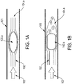
- Fig. 1a and Fig. 1b show schematic illustrations of blood flow around a stream-line shaped object 100.a and around a bluff body 100.b in a blood vessel 101 at a fixed time.
- An incoming blood flow 102 in a main direction of blood flow that is indicated by the arrows 103 is the same in both figures and generally illustrated by straight flow lines upstream of the bluff body.
- a stream-lined shape of the object 100.a does not generate vortices in the blood flow behind the object 104.a.
- the bluff body 100.b generates vortex shedding in the blood flow behind it.
- vortex shedding is known per se as an oscillating flow that occurs under suitable circumstances when a fluid flows past a bluff body.
- the parameters relevant for vortex shedding to occur comprise a viscosity of the fluid, a flow velocity, as well as a size and shape of the object.
- the former can be characterized, for example, by a Reynolds number.
- the vortex shedding induced by the presence of the bluff body 100.b in the blood flow 102 generates a so-called Kármán vortex street 104.b downstream of the bluff body 100.b.
- Vortices are generated at alternating sides of the body and are associated with oscillations in the blood flow in a direction perpendicular to the main flow direction. At a given time, the vortices generated are distributed as exemplarily shown in Fig.1b .
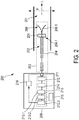
- Fig. 2 is a schematic illustration of an embodiment of an intravascular blood flow sensor system 200 for measuring blood flow inside a blood vessel 201.
- the intravascular blood flow sensor 200 comprises an intravascular blood flow sensor 203 that includes an intravascular guidewire 202 that has a guidewire body 204 with an atraumatic tip section 204.1 comprising a bluff part 205 that is suitably shaped for generation of vortices propagating along a main direction L of intravascular blood flow.
- the bluff part 205 of the intravascular blood flow sensor need not necessarily be different in shape from other parts of the guide wire body 204 for enabling the formation of vortices.
- the guidewire body 204 may have a rotational symmetry along its longitudinal direction, which in Fig. 2 corresponds to the direction L.
- the generation of vortices is alternatively or additionally made possible or enhanced by providing a shape of the microcatheter or guidewire that exhibits a break of a rotational symmetry in at least part of the tip.
- the tip section 204.1 includes a vibration sensor 206.
- the vibration sensor 206 comprises a flagellum 206.1 extending from a front surface of the tip section 204.1 in the main direction L of the intravascular blood flow.
- the flagellum 206.1 is elastically deformable in a direction P perpendicular to L which in the present example are the two mutually opposite directions P.
- An oscillating bending motion of the flagellum 206.1 in the direction P is driven by the vortex-generated oscillating motion of blood, as explained with reference to Fig. 1b .
- the propagating vortices thus show a respective distribution that alternates vortices at different downstream positions of the tip section 204.1 in the longitudinal direction L (as exemplarily shown in Fig. 1b ).
- Vortex-generated oscillations may occur in any direction that is perpendicular to the longitudinal direction L.
- the vibration sensor is thus configured to provide a vibration sensor signal indicative of the blood flow oscillations, but not necessarily of the propagation direction of the vortices.
- the flagellum 206.1 is shown in Fig. 2 in two different phases of an oscillating bending motion corresponding to two different bending positions of the flagellum 206.1.
- a first phase of the oscillating motion is represented by a solid line, and a second phase is represented by a dotted line.
- the flagellum 206.1 comprised by the vibration sensor 206 can be made of an electro-active polymer material and configured to generate and provide the vibration sensor signal in the form of a time-varying electrical signal having an amplitude depending on a deformation amount in the direction perpendicular to the main direction of intravascular blood flow.
- the intravascular blood flow sensor 200 also comprises a signal processing unit 208 for determining a value of a blood flow quantity characterizing blood flow inside a blood vessel.
- the signal processing unit comprises a vibration sensor signal input 211 receives the vibration sensor signals from the vibration sensor of the intravascular blood flow sensor.
- the vibration sensor signal comprises a vibration sensor signal component caused by vortex-generated blood flow oscillations of intravascular blood flow.
- the vibration sensor signal component caused by the vortex-generated blood flow oscillations is a component in a direction perpendicular to the main direction of blood flow.
- the signal processing unit 208 further comprises a blood flow determination unit 213 with is configured to determine the vibration sensor signal component using the vibration sensor signal, to determine the oscillation frequency of the vortex-generated blood flow oscillations using the vibration sensor signal component, and to determine and provide the value of the blood flow quantity using the determined oscillation frequency.
- a blood flow determination unit 213 is configured to determine the vibration sensor signal component using the vibration sensor signal, to determine the oscillation frequency of the vortex-generated blood flow oscillations using the vibration sensor signal component, and to determine and provide the value of the blood flow quantity using the determined oscillation frequency.
- these three distinct tasks are performed by three respective units 213.1, 213.2 and 213.3.
- the three described tasks are performed by a processor.
- Some signal processing units include a blood flow determination unit that additionally comprises a signal transformation unit (212), which is configured to determine a frequency-domain representation of the vibration sensor signal received during a predetermined measuring time span and to determine the oscillation frequency of the vortex-generated blood flow oscillations using the frequency-domain representation.
- the signal transformation unit 212 receives the vibration sensor signals from the vibration sensor signal input over a predetermined measuring time span associated with a given measuring time.
- the signal transformation unit 212 determines the oscillation frequency for the given measuring time using a frequency-domain representation of the vibration sensor signal during the respective measuring time span.
- the signal transformation unit 212 is a Fast Fourier Transform unit that determines the Fourier Transform of the vibration sensor signal. From the transformed vibration sensor signal, an oscillation frequency can be determined in a simple manner as a frequency of a Fourier component having a maximum amplitude in an expected oscillation frequency range above 100 Hz, typically in the range of a few hundred Hz.
- some signal processing units of the present embodiment further comprises a filter unit 214 that is configured to filter out frequency components from the vibration sensor signal that are associated with heart beat frequency.
- the heart beat frequency range is typically below 100 Hz.
- Some signal processing unit further determines a frequency ratio of the determined oscillation frequencies at two measuring times. This way, blood flow quantities can be determined. Such blood flow quantities provide important information regarding the current physiological state of a blood vessel, and assist in the identification and quantitative characterization of a stenosis.
- the measurements are made in a state of hyperemia and in a state of normal blood flow (e.g., at rest).
- the coronary flow reserve (CFR) is then determined and provided by the signal-processing unit with particular ease and reliability as the frequency ratio of respective vibration sensor signals at the measuring time corresponding to the state of hyperemia and at the measuring time corresponding to the state of normal blood flow.
- a user interface 210 is provided for user input of control signals, such as for triggering the oscillation measurements by controlling the operation of the vibration sensor signal input, and for output of the value of the blood flow quantity determined.
- the geometrical data is locally stored in a storage unit 215 which is accessed by the blood flow determination unit 213 for determining the value of the flow velocity v .
- the signal processing unit receives the geometrical data from an external imaging device or an external image processing device that is configured to image the blood vessel at a current intravascular position of the intravascular blood flow sensor and to determine and provide the geometrical data at that position.
- the signal processing unit 208 determines and provides relative changes in blood flow over time from a sequence of measurements, as compared to a first measurement of the sequence that can be triggered by user input.
- the flagellum comprised by the vibration sensor 206 is an optical fiber segment configured to receive and guide light to and from a reflective fiber-segment tip.
- These particular intravascular flow sensors also comprise a light source that is configured to provide light for coupling into the fiber segment and a light sensor arranged to receive light reflected from the fiber-segment tip and modulated in intensity by oscillating deformation of the fiber segment.
- the light sensor is configured to provide the vibration sensor signal in the form of an electronic light-sensor signal indicative of a time-varying reflected light intensity.
- a further variant of the intravascular blood flow sensor of Fig. 2 which is not shown, comprises, instead of the guidewire 202, a microcatheter provided with the flagellum-type vibration sensor 206 in its tip section.
- a microcatheter provided with the flagellum-type vibration sensor 206 in its tip section.
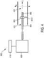
- Fig. 3 illustrates another exemplary embodiment of an intravascular blood flow sensor 300 for measuring blood flow inside a blood vessel 301.
- the blood flow sensor 300 comprises a micro-catheter for intravascular insertion.
- a catheter body 304 of the micro-catheter may have a rotational symmetry along its longitudinal direction, which in Fig. 3 corresponds to the direction L.
- a tip section 304.1 of the catheter body 304 forms a bluff body part and is suitably shaped for generation of vortices propagating along a main direction L of intravascular blood flow.
- the tip section 304.1 is elastically deformable by vortex-generated blood flow oscillations in the directions P perpendicular to the main direction L of intravascular blood flow.
- a vibration sensor 306 is arranged in the tip section 304.1.
- the vibration sensor 306 is a motion sensor, suitably an acceleration sensor. As such, it provides an electrical sensor signal indicative of an oscillatory bending motion of the tip section 304.1 driven by the vortex-generated oscillations of blood flow in the vessel 301 at the location of the tip section 304.1. This sensor signal thus forms a suitable vibration sensor signal that is indicative of the oscillation frequency of the vortex-generated blood flow oscillations that propagate in the direction L.
- the vibration sensor signals are provided by the vibration sensor and received by a signal processing unit 308, which is arranged outside the body of the patient. Details of signal communication and signal processing have been described in the context of the embodiment of Fig. 2 and are applicable here as well.
- a user may interact with the intravascular flow sensor 300 via a user interface 310, as also described above in more detail with reference to Fig. 2 .
- a variant of the intravascular blood flow sensor of Fig. 3 which is not shown, comprises, instead of the microcatheter 302, a guidewire provided with the vibration sensor 306 in its tip section.
- the above description is otherwise equally applicable to that variant.
- a variant of the intravascular blood flow sensor of Fig. 3 comprises an additional bluff part 312 in the microcatheter body 304 of the microcathether 302.
- the bluff part 312 is arranged at a short distance from the tip section 304.1 in direction of the proximal end of the microcatheter 302.
- the presence of the bluff part 312 further enhances vortex shedding that induces a vibration of the tip section 304.1, where the vibration sensor 306 is arranged.
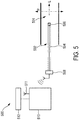
- Fig. 4 illustrates another embodiment of an intravascular blood flow sensor 400 for measuring blood flow inside a blood vessel 401.
- the intravascular blood flow sensor 400 comprises a microcatheter 402 with a catheter body 404 for intravascular insertion.
- a tip section 404.1 of the catheter body comprises a barrier section 405 that protrudes from the catheter body in a direction P perpendicular to the main direction of intravascular blood flow, in order to enhance the generation of vortices propagating along the main direction L of intravascular blood flow.
- Such a barrier 405 may also be present in the tip section in variants of the embodiments of Figs. 1 to 3 .
- the shape of the barrier section 405 is only schematically indicated in Fig. 4 . Any shape that is suitable to favor generation of vortices over laminar blood flow along the tip section 404.1 of the catheter body 404 can be used.
- a vibration sensor is provided in the form of a pressure sensor 406 located on a surface of the tip section 404.1 of the catheter body 404.
- the pressure sensor 406 is arranged and configured to measure pressure exerted in the direction P perpendicular to the main direction L of the turbulent intravascular blood flow, and thus particularly detects the vortex-generated blood flow oscillations as corresponding pressure oscillations.
- the pressure sensor 406 generates a vibration sensor signal in the form of a time-varying electrical signal depending on the pressure currently sensed.
- the pressure sensor 406 provides the vibration sensor signal to a signal processing unit 408, using one of the signal communication techniques explained in the context of the embodiment of Fig. 2 .
- a user may interact with the intravascular blood flow sensor 400 via a user interface 410, as also explained hereinabove.
- Intravascular blood flood devices comprising one or more pressure sensors such as the pressure sensor 406 can additionally determine a value of a fractional flow reserve (FFR).
- Fractional flow reserve is the ratio of blood pressure after i.e., distal to a stenosis and the blood pressure before the stenosis. This determination is based on evaluating a low frequency band of the measured time-varying electrical signal. As mentioned, Vortex-induced frequencies within the vibration signal typically are at frequencies in the range of a few 100 Hz and are overlaid with low-frequency signal components associated with the heartbeat. The latter components have a frequency clearly below 100 Hz, typically around 1 Hz. FFR can thus be determined from the low frequency pressure signal that depicts the pressure changes over the heart cycle while CFR can be determined from the high frequency vortex-induced component.
- a variant of the intravascular blood flow sensor of Fig. 4 which is not shown, comprises two pressure sensors on opposite sides of the of guide wire body 404. Then they can derive a flow sensing frequency signal by determining the differences between two pressure signals determined by the respective pressure sensors. The intravascular blood flow sensor is then configured to compute a blood pressure signal (for FFR) by averaging over the two signals determined by each of the two pressure sensors.
- a variant of the intravascular blood flow sensor of Fig. 4 which is not shown, comprises, instead of the microcatheter 402, a guidewire provided with the pressure sensor 406 in its tip section.
- the above description is otherwise equally applicable to that variant.
- Fig. 5 shows a further embodiment of an intravascular blood flow sensor 500 in an inserted state inside a blood vessel 501.
- the blood flow sensor 500 comprises a guidewire 502 with a guidewire body 504.
- the blood flow sensor 500 also comprises a vibration sensor 506 implemented as any of the different kinds of vibration sensors discussed with reference to the embodiments of Figs 2-4 .
- the blood flow sensor 500 further comprises a signal communication unit 508 that is configured to receive the vibration sensor signals from the vibration sensor 506 and to perform wireless transmission of the vibration sensor signals to the signal processing unit 510 using a carrier signal.
- the signal processing unit 510 has a corresponding signal communication unit, of which only an antenna 511 is shown, that is configured to receive the carrier signal and to extract the vibration sensor signals from the carrier signal.
- the signal processing unit 510 determines respective oscillation frequencies of vortex-generated blood flow oscillations at at least two different measuring times and determines and provides as an output a frequency ratio of the determined oscillation frequencies at the two measuring times.
- a user may interact with the blood flow sensor 500 via a user interface 512, as explained above.
- the user input may also be provided using wireless communication.
- the signal communication unit 508 is to be located outside the living being under examination.
- the signal communication unit 508 is integrated into the guidewire body 504 and thus inserted in the blood vessel during operation.
- the transmission of the vibration sensor signals is suitably performed using radio communication protocols such as for example any of the IEEE 801.11 standards for wireless communication, a Bluetooth-based wireless communication protocol, or any other radio-based wireless communication protocol.
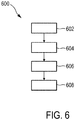
- Fig. 6 shows a flow diagram of a method 600 for controlling operation of an intravascular blood flow sensor.
- the method comprises a step 602 in which an intravascular blood flow sensor for measuring blood flow inside a blood vessel is provided.
- the intravascular blood flow sensor comprises a guidewire or catheter for intravascular insertion having a bluff part that is shaped for generation of vortices propagating along a main direction of intravascular blood flow and a vibration sensor arranged and configured to provide a vibration sensor signal indicative of an oscillation frequency of vortex-generated blood flow oscillations in a direction perpendicular to the main direction of intravascular blood flow.
- a vibration sensor signal is measured at two different measuring times using the vibration sensor.
- respective oscillation frequencies of the vortex-generated blood flow oscillations at the two different measuring times are determined.
- a frequency ratio of the determined oscillation frequencies at the two measuring times is determined.
- a signal processing unit receives the vibration sensor signals and determines respective oscillation frequencies of the vortex-generated blood flow oscillations at at least two different measuring times, and a frequency ratio of the determined oscillation frequencies at the two measuring times.
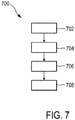
- Fig. 7 shows a flow diagram describing a method 700 for operating a signal processing unit for determining a value of a blood flow quantity characterizing blood flow inside a blood vessel.
- the method comprises a step 702 in which a signal processing unit receives a vibration sensor signal from an intravascular blood flow sensor, the vibration sensor signal comprising a vibration sensor signal component caused by vortex-generated blood flow oscillations of intravascular blood flow.
- the signal processing unit determines the vibration sensor signal component using the vibration sensor signal.
- the signal processing unit determines the oscillation frequency of the vortex-generated blood flow oscillations using the vibration sensor signal component, and finally, in a step 708, the signal processing unit determines, using the oscillation frequency of the vortex-generated blood flow oscillations, and provides, the value of the blood flow quantity.
- a signal processing unit for determining a value of a blood flow quantity characterizing blood flow inside a blood vessel comprises a vibration sensor signal input, which is configured to receive a vibration sensor signal from an intravascular blood flow sensor, the vibration sensor signal comprising a vibration sensor signal component caused by vortex-generated blood flow oscillations of intravascular blood flow, and a blood flow determination unit which is configured to determine the vibration sensor signal component using the vibration sensor signal, to determine the oscillation frequency of the vortex-generated blood flow oscillations using the vibration sensor signal component and to determine and provide the value of the blood flow quantity using the determined oscillation frequency.
- a computer program may be stored/distributed on a suitable medium, such as an optical storage medium or a solid-state medium, supplied together with or as part of other hardware, but may also be distributed in other forms, such as via the Internet or other wired or wireless telecommunication systems.
- a suitable medium such as an optical storage medium or a solid-state medium, supplied together with or as part of other hardware, but may also be distributed in other forms, such as via the Internet or other wired or wireless telecommunication systems.
Priority Applications (11)
| Application Number | Priority Date | Filing Date | Title |
|---|---|---|---|
| EP17162723.5A EP3378381A1 (fr) | 2017-03-24 | 2017-03-24 | Détermination du débit sanguin intravasculaire basée sur la formation de vortex |
| EP18711107.5A EP3599997A1 (fr) | 2017-03-24 | 2018-03-16 | Unité de traitement de signal pour détermination de flux sanguin intravasculaire |
| JP2019551644A JP2020511253A (ja) | 2017-03-24 | 2018-03-16 | 渦放出に基づく血管内血流の感知 |
| PCT/EP2018/056644 WO2018172201A1 (fr) | 2017-03-24 | 2018-03-16 | Détection d'écoulement sanguin intravasculaire basée sur un décollement par vortex |
| CN201880020715.XA CN110461216A (zh) | 2017-03-24 | 2018-03-16 | 基于涡旋脱落的血管内血流感测 |
| EP18711106.7A EP3599996A1 (fr) | 2017-03-24 | 2018-03-16 | Détection d'écoulement sanguin intravasculaire basée sur un décollement par vortex |
| CN201880033635.8A CN110678118A (zh) | 2017-03-24 | 2018-03-16 | 用于血管内血流确定的信号处理单元 |
| US16/493,112 US20200113448A1 (en) | 2017-03-24 | 2018-03-16 | Intravascular blood flow sensing based on vortex shedding |
| JP2019551646A JP2020511254A (ja) | 2017-03-24 | 2018-03-16 | 血管内血流の決定のための信号処理ユニット |
| US16/492,961 US20200008688A1 (en) | 2017-03-24 | 2018-03-16 | Signal processing unit for intravascular blood flow determination |
| PCT/EP2018/056645 WO2018172202A1 (fr) | 2017-03-24 | 2018-03-16 | Unité de traitement de signal pour détermination de flux sanguin intravasculaire |
Applications Claiming Priority (1)
| Application Number | Priority Date | Filing Date | Title |
|---|---|---|---|
| EP17162723.5A EP3378381A1 (fr) | 2017-03-24 | 2017-03-24 | Détermination du débit sanguin intravasculaire basée sur la formation de vortex |
Publications (1)
| Publication Number | Publication Date |
|---|---|
| EP3378381A1 true EP3378381A1 (fr) | 2018-09-26 |
Family
ID=58428109
Family Applications (3)
| Application Number | Title | Priority Date | Filing Date |
|---|---|---|---|
| EP17162723.5A Withdrawn EP3378381A1 (fr) | 2017-03-24 | 2017-03-24 | Détermination du débit sanguin intravasculaire basée sur la formation de vortex |
| EP18711106.7A Withdrawn EP3599996A1 (fr) | 2017-03-24 | 2018-03-16 | Détection d'écoulement sanguin intravasculaire basée sur un décollement par vortex |
| EP18711107.5A Withdrawn EP3599997A1 (fr) | 2017-03-24 | 2018-03-16 | Unité de traitement de signal pour détermination de flux sanguin intravasculaire |
Family Applications After (2)
| Application Number | Title | Priority Date | Filing Date |
|---|---|---|---|
| EP18711106.7A Withdrawn EP3599996A1 (fr) | 2017-03-24 | 2018-03-16 | Détection d'écoulement sanguin intravasculaire basée sur un décollement par vortex |
| EP18711107.5A Withdrawn EP3599997A1 (fr) | 2017-03-24 | 2018-03-16 | Unité de traitement de signal pour détermination de flux sanguin intravasculaire |
Country Status (5)
| Country | Link |
|---|---|
| US (2) | US20200113448A1 (fr) |
| EP (3) | EP3378381A1 (fr) |
| JP (2) | JP2020511253A (fr) |
| CN (2) | CN110461216A (fr) |
| WO (2) | WO2018172202A1 (fr) |
Families Citing this family (5)
| Publication number | Priority date | Publication date | Assignee | Title |
|---|---|---|---|---|
| CN111918612A (zh) * | 2018-06-05 | 2020-11-10 | 谷和雄 | 血流量测定系统 |
| KR20210027905A (ko) * | 2019-09-03 | 2021-03-11 | 고려대학교 산학협력단 | Mri를 이용한 뇌혈관 예비능 측정방법 |
| CN111412956A (zh) * | 2020-03-27 | 2020-07-14 | 天津大学 | 一种基于加速度测量的涡街探头 |
| CN111412957A (zh) * | 2020-03-27 | 2020-07-14 | 天津大学 | 一种基于加速度测量的涡街信号检测方法 |
| JP7405164B2 (ja) | 2021-03-31 | 2023-12-26 | Jfeスチール株式会社 | 流量計測装置及び方法 |
Citations (3)
| Publication number | Priority date | Publication date | Assignee | Title |
|---|---|---|---|---|
| US276137A (en) | 1883-04-17 | Telephone-transmitter | ||
| US20130274712A1 (en) * | 2011-11-02 | 2013-10-17 | Stuart O. Schecter | Haptic system for balloon tipped catheter interventions |
| US20140276124A1 (en) * | 2013-03-15 | 2014-09-18 | St. Jude Medical, Cardiology Division, Inc. | Quantification of renal denervation via alterations in renal blood flow pre/post ablation |
Family Cites Families (13)
| Publication number | Priority date | Publication date | Assignee | Title |
|---|---|---|---|---|
| US4523477A (en) * | 1983-08-04 | 1985-06-18 | The Foxboro Company | Planar-measuring vortex-shedding mass flowmeter |
| CN1083208A (zh) * | 1992-08-25 | 1994-03-02 | 电子科技大学 | 一种光纤流量计 |
| JPH09294730A (ja) * | 1996-05-02 | 1997-11-18 | Hagiwara Denki Kk | シャント形成部位における振動検出センサ |
| CN2564118Y (zh) * | 2002-08-16 | 2003-08-06 | 邓小燕 | 漩流导引腔静脉滤器 |
| EP1936332A1 (fr) * | 2006-12-22 | 2008-06-25 | Nederlandse Organisatie voor Toegepast-Natuuurwetenschappelijk Onderzoek TNO | Débitmètre utilisant des vortices de Karman comprenant un capteur à fibre optique à réseau de Bragg ainsi qu'un procédé de mesure d'un débit d'un fluide |
| CN104284648B (zh) * | 2012-03-14 | 2017-01-11 | 拉尔夫·齐珀 | 使用光疗法以及振动的改进的性刺激装置 |
| EP2956050A4 (fr) * | 2013-02-18 | 2016-10-26 | Univ Ramot | Rigidité artérielle due à une baisse de pression intravasculaire et réduction de l'effet de pression en mode commun |
| US20140276137A1 (en) | 2013-03-14 | 2014-09-18 | Volcano Corporation | Systems and methods for determining coronary flow reserve |
| US9820662B2 (en) * | 2013-10-25 | 2017-11-21 | Boston Scientific Scimed, Inc. | Catheter systems and methods for determining blood flow rates with optical sensing |
| CN105899141A (zh) * | 2014-01-10 | 2016-08-24 | 火山公司 | 检测与动脉瘤修复相关联的内漏 |
| US10213182B2 (en) * | 2014-03-26 | 2019-02-26 | Volcano Corporation | Devices, systems, and methods for assessing a vessel utilizing angled flow-sensing elements |
| CA2944114C (fr) * | 2014-04-04 | 2023-09-26 | St. Jude Medical Systems Ab | Systemes, dispositifs et procedes de diagnostic de donnees de pression intravasculaire et de debit |
| CN104739377B (zh) * | 2015-03-20 | 2018-01-23 | 武汉阿格斯科技有限公司 | 血管内同时进行oct成像和压力测量装置、系统及方法 |
-
2017
- 2017-03-24 EP EP17162723.5A patent/EP3378381A1/fr not_active Withdrawn
-
2018
- 2018-03-16 WO PCT/EP2018/056645 patent/WO2018172202A1/fr active Application Filing
- 2018-03-16 EP EP18711106.7A patent/EP3599996A1/fr not_active Withdrawn
- 2018-03-16 CN CN201880020715.XA patent/CN110461216A/zh active Pending
- 2018-03-16 US US16/493,112 patent/US20200113448A1/en not_active Abandoned
- 2018-03-16 JP JP2019551644A patent/JP2020511253A/ja active Pending
- 2018-03-16 US US16/492,961 patent/US20200008688A1/en not_active Abandoned
- 2018-03-16 WO PCT/EP2018/056644 patent/WO2018172201A1/fr active Application Filing
- 2018-03-16 JP JP2019551646A patent/JP2020511254A/ja active Pending
- 2018-03-16 EP EP18711107.5A patent/EP3599997A1/fr not_active Withdrawn
- 2018-03-16 CN CN201880033635.8A patent/CN110678118A/zh active Pending
Patent Citations (3)
| Publication number | Priority date | Publication date | Assignee | Title |
|---|---|---|---|---|
| US276137A (en) | 1883-04-17 | Telephone-transmitter | ||
| US20130274712A1 (en) * | 2011-11-02 | 2013-10-17 | Stuart O. Schecter | Haptic system for balloon tipped catheter interventions |
| US20140276124A1 (en) * | 2013-03-15 | 2014-09-18 | St. Jude Medical, Cardiology Division, Inc. | Quantification of renal denervation via alterations in renal blood flow pre/post ablation |
Non-Patent Citations (1)
| Title |
|---|
| JASON FOUST: "Blood flow simulation past a catheter positioned in the SVC-IVC-RA junction : steady and unsteady flow considerations", 30 April 2004 (2004-04-30), XP055403678, Retrieved from the Internet <URL:http://preserve.lehigh.edu/cgi/viewcontent.cgi?article=1846&context=etd> [retrieved on 20170904] * |
Also Published As
| Publication number | Publication date |
|---|---|
| US20200008688A1 (en) | 2020-01-09 |
| CN110461216A (zh) | 2019-11-15 |
| JP2020511253A (ja) | 2020-04-16 |
| WO2018172202A1 (fr) | 2018-09-27 |
| WO2018172201A1 (fr) | 2018-09-27 |
| US20200113448A1 (en) | 2020-04-16 |
| EP3599996A1 (fr) | 2020-02-05 |
| EP3599997A1 (fr) | 2020-02-05 |
| JP2020511254A (ja) | 2020-04-16 |
| CN110678118A (zh) | 2020-01-10 |
Similar Documents
| Publication | Publication Date | Title |
|---|---|---|
| US20200008688A1 (en) | Signal processing unit for intravascular blood flow determination | |
| US11717266B2 (en) | Ultrasound method and apparatus for processing ultrasound image | |
| EP3324850B1 (fr) | Capteur de forme réelle à fibre optique pour l'affichage de mesure doppler amélioré | |
| US11666307B2 (en) | Devices, systems, and methods for real-time monitoring of fluid flow in an anuerysm | |
| CN104873182A (zh) | 血压测量装置和血压测量方法 | |
| CN105208923A (zh) | 用于与脉管内压力监测设备一起使用的接口设备、系统和方法 | |
| CN106132310B (zh) | 用于使用成角度的流速感测元件来评估血管的装置、系统和方法 | |
| JP2016123424A (ja) | 血圧測定システムおよび血行パラメータ決定方法 | |
| US20230142143A1 (en) | System and method for robust flow measurements in vessels | |
| EP2967490A1 (fr) | Imagerie ultrasonore à flux vectoriel (vfi) avec tracé de courbe | |
| JP2018023610A (ja) | 超音波測定装置および制御方法 | |
| US20150243190A1 (en) | Blood pressure measurement apparatus | |
| US20160128667A1 (en) | Method of calculating feature of blood vessel and ultrasound apparatus for performing the same | |
| EP3589186B1 (fr) | Mesure de débit sanguin intravasculaire | |
| JP2007111245A (ja) | 血液循環状態測定装置 | |
| CN109069113B (zh) | 超声成像设备及利用超声检测血管壁剪切指数的方法 | |
| US11226219B2 (en) | Fluid measurement apparatus, fluid measurement method, and program | |
| JP5947566B2 (ja) | 血流計測装置 | |
| JP7083993B2 (ja) | 超音波映像システム及び超音波映像装置 | |
| Hangiandreou et al. | Principles of Color and Power Doppler in Neck Ultrasound Imaging |
Legal Events
| Date | Code | Title | Description |
|---|---|---|---|
| PUAI | Public reference made under article 153(3) epc to a published international application that has entered the european phase |
Free format text: ORIGINAL CODE: 0009012 |
|
| AK | Designated contracting states |
Kind code of ref document: A1 Designated state(s): AL AT BE BG CH CY CZ DE DK EE ES FI FR GB GR HR HU IE IS IT LI LT LU LV MC MK MT NL NO PL PT RO RS SE SI SK SM TR |
|
| AX | Request for extension of the european patent |
Extension state: BA ME |
|
| STAA | Information on the status of an ep patent application or granted ep patent |
Free format text: STATUS: THE APPLICATION IS DEEMED TO BE WITHDRAWN |
|
| 18D | Application deemed to be withdrawn |
Effective date: 20190327 |