EP3377394B1 - Active deflector - Google Patents
Active deflector Download PDFInfo
- Publication number
- EP3377394B1 EP3377394B1 EP16809482.9A EP16809482A EP3377394B1 EP 3377394 B1 EP3377394 B1 EP 3377394B1 EP 16809482 A EP16809482 A EP 16809482A EP 3377394 B1 EP3377394 B1 EP 3377394B1
- Authority
- EP
- European Patent Office
- Prior art keywords
- deflector
- spl
- wheel
- whl
- actuator
- Prior art date
- Legal status (The legal status is an assumption and is not a legal conclusion. Google has not performed a legal analysis and makes no representation as to the accuracy of the status listed.)
- Active
Links
- 238000000034 method Methods 0.000 claims description 6
- 238000011144 upstream manufacturing Methods 0.000 claims description 3
- 230000000694 effects Effects 0.000 description 2
- 230000006870 function Effects 0.000 description 2
- 230000000750 progressive effect Effects 0.000 description 2
- 235000012431 wafers Nutrition 0.000 description 2
- XLYOFNOQVPJJNP-UHFFFAOYSA-N water Substances O XLYOFNOQVPJJNP-UHFFFAOYSA-N 0.000 description 2
- 238000010276 construction Methods 0.000 description 1
- 238000001816 cooling Methods 0.000 description 1
- 238000006073 displacement reaction Methods 0.000 description 1
- 239000000428 dust Substances 0.000 description 1
- 239000003344 environmental pollutant Substances 0.000 description 1
- 239000012530 fluid Substances 0.000 description 1
- 239000000446 fuel Substances 0.000 description 1
- 239000011499 joint compound Substances 0.000 description 1
- 239000000463 material Substances 0.000 description 1
- 230000035515 penetration Effects 0.000 description 1
- 231100000719 pollutant Toxicity 0.000 description 1
Images


Classifications
-
- B—PERFORMING OPERATIONS; TRANSPORTING
- B62—LAND VEHICLES FOR TRAVELLING OTHERWISE THAN ON RAILS
- B62D—MOTOR VEHICLES; TRAILERS
- B62D35/00—Vehicle bodies characterised by streamlining
- B62D35/005—Front spoilers
-
- B—PERFORMING OPERATIONS; TRANSPORTING
- B62—LAND VEHICLES FOR TRAVELLING OTHERWISE THAN ON RAILS
- B62D—MOTOR VEHICLES; TRAILERS
- B62D35/00—Vehicle bodies characterised by streamlining
- B62D35/02—Streamlining the undersurfaces
-
- B—PERFORMING OPERATIONS; TRANSPORTING
- B62—LAND VEHICLES FOR TRAVELLING OTHERWISE THAN ON RAILS
- B62D—MOTOR VEHICLES; TRAILERS
- B62D37/00—Stabilising vehicle bodies without controlling suspension arrangements
- B62D37/02—Stabilising vehicle bodies without controlling suspension arrangements by aerodynamic means
-
- Y—GENERAL TAGGING OF NEW TECHNOLOGICAL DEVELOPMENTS; GENERAL TAGGING OF CROSS-SECTIONAL TECHNOLOGIES SPANNING OVER SEVERAL SECTIONS OF THE IPC; TECHNICAL SUBJECTS COVERED BY FORMER USPC CROSS-REFERENCE ART COLLECTIONS [XRACs] AND DIGESTS
- Y02—TECHNOLOGIES OR APPLICATIONS FOR MITIGATION OR ADAPTATION AGAINST CLIMATE CHANGE
- Y02T—CLIMATE CHANGE MITIGATION TECHNOLOGIES RELATED TO TRANSPORTATION
- Y02T10/00—Road transport of goods or passengers
- Y02T10/80—Technologies aiming to reduce greenhouse gasses emissions common to all road transportation technologies
- Y02T10/82—Elements for improving aerodynamics
-
- Y—GENERAL TAGGING OF NEW TECHNOLOGICAL DEVELOPMENTS; GENERAL TAGGING OF CROSS-SECTIONAL TECHNOLOGIES SPANNING OVER SEVERAL SECTIONS OF THE IPC; TECHNICAL SUBJECTS COVERED BY FORMER USPC CROSS-REFERENCE ART COLLECTIONS [XRACs] AND DIGESTS
- Y02—TECHNOLOGIES OR APPLICATIONS FOR MITIGATION OR ADAPTATION AGAINST CLIMATE CHANGE
- Y02T—CLIMATE CHANGE MITIGATION TECHNOLOGIES RELATED TO TRANSPORTATION
- Y02T10/00—Road transport of goods or passengers
- Y02T10/80—Technologies aiming to reduce greenhouse gasses emissions common to all road transportation technologies
- Y02T10/88—Optimized components or subsystems, e.g. lighting, actively controlled glasses
Definitions
- the invention particularly relates to a deflection device placed in front of a motor vehicle wheel.
- the aerodynamics of a motor vehicle is an important feature because it influences in particular the fuel consumption (and therefore the pollution) as well as the performance of said vehicle. This is particularly important when the motor vehicle is traveling at high speed.
- the drag force exerted on a motor vehicle is quantified using a reference surface S.
- the drag force denoted Fx
- Fx the drag force
- q * S * Cx the drag force
- Cx denoting a drag coefficient specific to the vehicle.
- the reference surface used for a motor vehicle is usually its front surface. To reduce drag, it is common to reduce the reference area. But to reduce the drag even more, it is possible to influence other parameters.
- AGS from the English language expression "Active Grille Shutter”, or active calender shutter.
- AGS from the English language expression "Active Grille Shutter”, or active calender shutter.
- the device makes it possible to open or close the air access via a motor vehicle grille. In the open position, the air can circulate through the shell and participate in cooling the engine of the motor vehicle. In the closed position, the air does not enter via the grille which reduces the drag.
- the wheel arch is a cavity built into the body of the vehicle, and surrounding a wheel (this corresponds to the wing of the vehicle).
- the wheel arch fulfills several functions. In particular, it limits (by retaining them) projections of water, mud or other materials on which the wheel is likely to circulate and that it may be caused to expel during its rotation.
- an external fairing has only limited effectiveness and a fixed deflector may be damaged during obstacle clearance (sidewalk, speed bump type, etc.).
- the invention aims to improve the situation.
- the invention relates to a deflection device adapted to be fixed upstream with respect to the air flow of a motor vehicle wheel in order to reduce the aerodynamic drag of said wheel, the device comprising a deflector and a actuator, the actuator being arranged to deploy and retract the deflector in front of said wheel.
- a deflection device adapted to be fixed upstream with respect to the air flow of a motor vehicle wheel in order to reduce the aerodynamic drag of said wheel
- the device comprising a deflector and a actuator, the actuator being arranged to deploy and retract the deflector in front of said wheel.
- Such a deflection device is advantageous in particular in that it makes it possible to ensure a reduction of the drag at the level of the wheel and that it is able to guard against the damage related to obstacles being crossed by the wheel. .
- the deflector is provided with at least one air passage shutter, the device being arranged to open each shutter when the actuator starts to deploy the deflector, and to close each shutter when the actuator finishes deploying the deflector.
- the invention relates in particular to a deflection device in which each shutter comprises a plate arranged to slide in the deflector plane, the plate being provided with at least one opening.
- the invention relates in particular to a deflection device in which each shutter comprises a flap.
- the invention relates in particular to a deflection device in which the actuator of the device is arranged to open and to close each shutter.
- the invention relates in particular to a deflection device wherein the baffle is rotatable about an axis parallel to the axis of the wheel.
- the invention relates in particular to a deflection device in which the deflector has the same width as the wheel.
- the invention relates in particular to a deflection device arranged to control the deployment of the deflector when the speed of the device exceeds a predetermined threshold, and to control the retraction of the deflector when said speed passes below a predetermined threshold.
- the invention relates in particular to a deflection device arranged to deploy the deflector to a distance of about 80mm from the ground on which the wheel rests.
- the invention relates in particular to a deflection device in which the deflector is placed in a horizontal position relative to the ground on which the wheel rests when it is in the retracted position.
- the invention relates in particular to a deflection device in which the deflector is placed in an inclined position relative to the ground on which rests the wheel when in the deployed position.
- the invention also relates to a method for controlling aerodynamic drag affecting a motor vehicle wheel, comprising a step of deploying such a deflector in front of said wheel with the aid of an actuator in order to reduce said drag, and a step of retracting said deflector with said actuator when the reduction of said drag is no longer appropriate.
- This method constitutes an advantageous use of a deflection device according to one embodiment of the invention.
- the Figure 1A illustrates a vertical section of a motor vehicle in a longitudinal direction of the vehicle.
- the vehicle is shown in displacement situation.
- a relative wind AIR therefore exerts pressure on the vehicle.
- This relative wind creates turbulence TRB in a wheel well WH (in English, "wheelhouse") of the vehicle.
- the vehicle includes a deflector device including an SPL baffle and an ACT actuator.
- ACT actuator is for example a servomotor or any suitable electric motor.
- ACT actuator is shown schematically.
- the SPL deflector shown takes the form of a straight cylinder portion articulated at the axis of symmetry of the right cylinder.
- the represented SPL deflector comprises six shutters SHT (English, "shutter”). It totally retracted, and the SHT shutters are closed.
- the Figure 1B illustrates the motor vehicle of the Figure 1A , in front view. Only the left half of the vehicle is shown. We see on this Figure 1B , as on the Figure 1A , that the WHL wheel is not protected by the SPL deflector, which is fully retracted.
- the Figure 2A represents the vehicle of the Figure 1A (according to the same vertical section as on the Figure 1A ), in which SPL deflector is partially (half) deployed.
- the six SHT flaps are open to allow the relative wind AIR to pass and to limit ACT actuator effort required to continue deploying the SPL baffle.
- the Figure 2B illustrates the motor vehicle of the Figure 2A , in front view. Only the left half of the vehicle is shown.
- the wheel WHL is partially protected by the deflector SPL, which is partially deployed, and which lets pass a part of the relative wind.
- the six SHT shutters represented as parallel segments. The surfaces that make up these six flaps are substantially parallel to the ground on which the vehicle is moving, in order to offer a minimum resistance to the relative wind during deployment of the deflector. In front view, they appear schematically as horizontal segments.
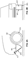
- the figure 3A represents the vehicle of Figures 1A and 2A , according to the same vertical section, in which SPL deflector is fully deployed.
- the six SHT flaps are closed, so as to deflect the relative wind and to prevent as much as possible the entry of the relative wind into the wheel well WH.
- the figure 3B illustrates the motor vehicle of the figure 3A , in front view. Only the left half of the vehicle is shown.
- the WHL wheel is largely protected by the SPL deflector, which is fully deployed. This full deployment occurs over most of the height separating the ground on which circulates the motor vehicle of the axis of rotation of the deflector (which is in this case at the rocker).
- the six shutters SHT which are closed, collectively form a continuous surface, airtight. They are not reproduced in the figure because not visible in a schematic representation.
- the SPL deflector thus deviates most of the relative wind, and protects the wheel well from turbulence that would otherwise lead to a much greater aerodynamic drag.
- a first embodiment relates to a deflection device.
- the device is adapted to be fixed in front of a wheel WHL of a motor vehicle, in order to reduce the aerodynamic drag of said wheel WHL.
- the device includes an SPL baffle. It further comprises an actuator ACT arranged to deploy the deflector SPL in front of said wheel WHL, as well as to retract said deflector SPL in front of said wheel WHL.
- the SPL deflector is located upstream of the WHL wheel with respect to the flow of air.
- front is meant that the deflector SPL is between the front of the motor vehicle (for example its front bumper) and the wheel WHL.
- the deflector is deployed by resorting to a rotational movement of said reflector.
- the deflector is deployed via a translational movement of said reflector.
- the deflector can thus take the form of a guided plate along a pair of rails.
- the deflector SPL of a device according to the first embodiment is provided with at least one air passage shutter, the device being arranged to open each shutter when the actuator begins to deploy the SPL baffle, and to close each shutter when the actuator finishes deploying the SPL baffle.
- the shutter can take various forms.
- the deflector comprises a single shutter.
- the deflector comprises several shutters, which are either all identical or different from each other.
- each shutter of a device comprises a plate arranged to slide in the plane of the deflector, a portion of the plate being provided with at least one opening.
- the wafer is rectangular in shape, half of the rectangle being full (and therefore airtight), the other half comprising one or more holes.
- the baffle comprises, for example, a plate forming a plane whose so-called outer face is exposed to air, and of which a so-called internal opposite face comprises guide rails for the one or more wafers.
- This plate is, according to one possible implementation, provided, for each shutter, a respective window.
- Each window may in particular consist of an orifice having the shape of a disk or a parallelepiped.
- Each plate arranged to slide parallel to this plate, lets the air pass when its opening (or its openings if it has more than one) is at the level of the respective window, but prevents the passage of air when the formed surface by its opening has no intersection with the surface of the respective window.
- the SPL deflector of a device according to the first embodiment is provided with SHT flaps.
- the device is arranged to open the SHT flaps when the actuator begins to deploy the SPL baffle, and to close the SHT flaps when the actuator finishes deploying the SPL baffle.
- the SHT flaps are immediately opened.
- a more gradual opening is also possible.
- the SHT flaps are only closed when the deflector is deployed when this deployment is completed.
- the closure of the SHT flaps is more gradual and begins before complete completion of the deflector deployment. It is possible to combine an immediate opening with a progressive closure, and reciprocally a progressive opening with an immediate closure.
- the device keeps the SHT flaps substantially parallel to the ground on which the vehicle is traveling during the entire deployment of the deflector, which may involve varying an orientation command of these flaps throughout the deployment.
- the kinematics flaps is symmetrical to that of the deployment phase of the deflector. This can be advantageous from the point of view of the simplicity of the device.
- the SHT flaps are kept closed during the retraction of the SPL deflector.
- the effort required to retract the reflector can be reduced by taking advantage of the force resulting from the relative wind. This is particularly the case when the deployment and retraction of the deflector result from a rotational movement as illustrated on the Figures 1A , 2A and 3A .
- the actuator ACT of a device is arranged to open and close each shutter. It can thus close the shutters SHT, when the shutters take the form of shutters.
- This is advantageous because it simplifies the construction of the deflector device which requires only one ACT actuator to drive both the SPL deflector and its SHT flaps.
- a kinematics of retraction of the deflector symmetrical deflector deployment kinematics is simpler to implement an asymmetrical kinematics as envisaged in a variant above.
- the deflector SPL of a device according to one of the first to fifth embodiments is rotatable about an axis parallel to the axis of the wheel WHL. This allows the deployment and retraction of the SPL baffle by a rotational movement.
- the Figures 1A to 3A illustrate such an embodiment.
- the SPL deflector of a device according to one of the first to sixth embodiments has the same width as the WHL wheel. This is advantageous because it makes it possible not to increase the reference surface of the vehicle, which is decisive for the aerodynamic drag.
- a device is arranged to control the deployment of the deflector SPL when the speed of the device exceeds a predetermined threshold, and to control the retraction of the deflector SPL when said speed passes under a predetermined threshold.
- the device comprises for example an electronic circuit such as a microprocessor or a microcontroller receiving a speed information from a speed sensor, and ordering deployment deploying or retracting the baffle accordingly.
- a hysteresis mechanism is provided in order to avoid threshold effects.
- the actuator triggers the deployment of the deflector as soon as the speed exceeds a given threshold (for example 50km / h), but that the actuator only triggers the retraction of the deflector when the speed drops below a threshold lower than the aforementioned threshold (for example a threshold of 40km / h).
- the circuit avoids inadvertently trigger alternations of deployment and retraction when the vehicle is traveling at a speed close to the initial threshold and passes permanently from one side to the other of this threshold.
- the deployment trigger (eg 50km / h) is chosen to be high enough for deployment to have a noticeable effect on aerodynamic drag.
- the drag varies with the square of the speed. For low speeds, the drag itself is very low. Deploying the baffle is not helpful.
- the triggering threshold of the retraction (for example 40 km / h) is chosen so as to be high enough so that the driver can not reasonably consider crossing obstacles (sidewalks, speed bumps, etc.) at the speed considered. Thus, it prevents the motor vehicle is brought to cross such an obstacle (such as to damage the deflector) while the deflector is deployed.
- a device is arranged to deploy the deflector to a distance of about 80 mm from the ground on which the WHL wheel rests.
- the distance considered is the distance, in a direction perpendicular to the ground on which the motor vehicle is traveling, between the lowest point of the deflector and the ground.
- the extent of the deployment is adjustable (eg using a screw), in order to choose a distance value to the ground in a given range (for example between 60mm and 100mm).
- the deflector is provided with a distance sensor.
- the device is then arranged to interrupt deployment of the deflector when a low end of the deflector reaches a predefined distance (for example 80mm from the ground).
- a predefined distance for example 80mm from the ground.
- Such a sensor may be advantageous in the event that there is a significant margin in the fixing position of the deflection device on the motor vehicle in question.
- Such a sensor may also be advantageous in the event that the deflection device is likely to be installed on different types of vehicles. In these cases, the deflection device does not necessarily know its distance to the ground, and the sensor allows to set the deployment limit automatically without having to adjust.
- the distance sensor can (in addition or alternatively) order a retraction (possibly partial) when it detects that the deflector is too close to the ground, even if the vehicle would travel at a speed greater than the retraction threshold. This can happen if the vehicle crosses an obstacle at high speed. This can prevent damage to the baffle if the actuator is fast enough.
- the distance sensor can be used to disengage the deflector if it is too close to the ground.
- the declutching would spontaneously lead to retract somewhat the deflector (thanks to the relative wind), and would collect any impact with the ground without damaging the actuator (disengaged), and limiting the damage to the deflector.
- the SPL deflector of a device is placed in a horizontal position relative to the ground on which the WHL wheel rests when it is in the retracted position.
- the surface of the deflector which is exposed to the relative wind is assumed to be flat.
- the position horizontal is then defined relative to the plane of the deflector which is exposed to the relative wind. The position is said to be horizontal when this plane is substantially parallel to the ground on which the motor vehicle is traveling.
- the eventual SHT flaps of the deflector are closed. This is advantageous and avoids the penetration of various pollutants (water, dust, mud, etc.) from outside the vehicle through the openings that would open SHT flaps.
- the SPL deflector of a device is placed in an inclined position relative to the ground on which the WHL wheel rests when it is in the deployed position.
- the surface of the deflector which is exposed to the relative wind is assumed to be flat.
- the inclination of the deflector is then defined relative to the plane of the deflector which is exposed to the relative wind.
- the baffle may be tilted about 135 ° to the ground, as shown in the illustration. figure 3A .
- the position is said inclined when it is neither horizontal nor vertical.
- a method for controlling aerodynamic drag affecting a motor vehicle WHL wheel comprises a step of deploying an SPL deflector in front of said wheel WHL with the aid of an actuator ACT. This makes it possible to reduce said drag.
- the method further comprises a step of retracting said deflector SPL to using said actuator ACT when the reduction of said drag is no longer appropriate.
- the method can implement the various functions of the deflection device described above. In particular, it can control the deflector deployment stop using a distance sensor, control the opening and closing of any deflector flaps, etc.
Landscapes
- Engineering & Computer Science (AREA)
- Chemical & Material Sciences (AREA)
- Combustion & Propulsion (AREA)
- Transportation (AREA)
- Mechanical Engineering (AREA)
- Physics & Mathematics (AREA)
- Fluid Mechanics (AREA)
- Cooling, Air Intake And Gas Exhaust, And Fuel Tank Arrangements In Propulsion Units (AREA)
- Body Structure For Vehicles (AREA)
Description
L'invention a notamment pour objet un dispositif de déflection placé devant une roue de véhicule automobile.The invention particularly relates to a deflection device placed in front of a motor vehicle wheel.
L'aérodynamisme d'un véhicule automobile est une caractéristique importante car il influence notamment la consommation de carburant (et donc la pollution) ainsi que les performances dudit véhicule. Ceci est particulièrement important lorsque le véhicule automobile se déplace à haute vitesse.The aerodynamics of a motor vehicle is an important feature because it influences in particular the fuel consumption (and therefore the pollution) as well as the performance of said vehicle. This is particularly important when the motor vehicle is traveling at high speed.
En mécanique des fluides, on quantifie la force de traînée qui s'exerce sur un véhicule automobile à l'aide d'une surface de référence S. En première approximation, la force de traînée, notée Fx, est égale à q*S*Cx, q désignant la pression dynamique (q = ½ ρ*V2, ρ désignant la masse volumique de l'air et V la vitesse du véhicule par rapport à l'air), Cx désignant un coefficient de traînée propre au véhicule. La surface de référence utilisée pour un véhicule automobile est habituellement sa surface frontale. Afin de réduire la traînée, il est courant de réduire la surface de référence. Mais pour réduire la traînée encore davantage, il est possible d'influer sur d'autres paramètres. Il est notamment connu d'installer un dispositif désigné par l'acronyme AGS (provenant de l'expression de langue anglaise "Active Grille Shutter", ou obturateur actif de calandre). Le dispositif permet d'ouvrir ou de fermer l'accès de l'air via une calandre de véhicule automobile. En position ouverte, l'air peut circuler à travers la calandre et participer au refroidissement du moteur du véhicule automobile. En position fermée, l'air ne pénètre pas via la calandre ce qui réduit la traînée.In fluid mechanics, the drag force exerted on a motor vehicle is quantified using a reference surface S. As a first approximation, the drag force, denoted Fx, is equal to q * S * Cx, q designating the dynamic pressure (q = ½ ρ * V 2 , ρ denoting the density of the air and V the speed of the vehicle relative to the air), Cx denoting a drag coefficient specific to the vehicle. The reference surface used for a motor vehicle is usually its front surface. To reduce drag, it is common to reduce the reference area. But to reduce the drag even more, it is possible to influence other parameters. It is in particular known to install a device designated by the acronym AGS (from the English language expression "Active Grille Shutter", or active calender shutter). The device makes it possible to open or close the air access via a motor vehicle grille. In the open position, the air can circulate through the shell and participate in cooling the engine of the motor vehicle. In the closed position, the air does not enter via the grille which reduces the drag.
Lorsqu'un véhicule automobile se déplace, l'air dans lequel il évolue est dévié en fonction du profil du véhicule. L'air ainsi dévié atteint notamment le passage de roue. Le passage de roue est une cavité aménagée dans la carrosserie du véhicule, et entourant une roue (cela correspond à l'aile du véhicule). Le passage de roue remplit plusieurs fonctions. Il limite notamment (en les retenant) les projections d'eau, de boue ou d'autres matériaux sur lesquels la roue est susceptible de circuler et qu'elle peut être amenée à expulser lors de sa rotation.When a motor vehicle moves, the air in which it evolves is deflected according to the profile of the vehicle. The air thus deviated notably reaches the wheel well. The wheel arch is a cavity built into the body of the vehicle, and surrounding a wheel (this corresponds to the wing of the vehicle). The wheel arch fulfills several functions. In particular, it limits (by retaining them) projections of water, mud or other materials on which the wheel is likely to circulate and that it may be caused to expel during its rotation.
L'air atteignant le passage de roue circule notamment dans l'espace étroit séparant la roue du passage de roue. Il est connu qu'à cette occasion, des turbulences se forment autour des tours de roue et créent un frein aérodynamique. Certains véhicules automobiles, disposaient ainsi d'un carénage jusqu'à l'axe des roues arrière, à l'extérieur, ce qui réduisait les turbulences par l'extérieur. Il est également connu de placer un déflecteur fixe devant une roue de véhicule automobile. Un tel déflecteur fixe, qui peut prendre la forme d'une bavette (souvent d'environ 5cm de hauteur), réduit les turbulences dans le passage de roue.The air reaching the wheel well circulates in particular in the narrow space between the wheel and the wheel arch. It is known that on this occasion, turbulences are formed around wheel turns and create an aerodynamic brake. Some motor vehicles, thus had a fairing up to the axis of the rear wheels, outside, which reduced turbulence from the outside. It is also known to place a fixed deflector in front of a motor vehicle wheel. Such a fixed deflector, which can take the form of a flap (often about 5cm in height), reduces turbulence in the wheel well.
Cependant, un carénage extérieur n'a qu'une efficacité limitée et un déflecteur fixe risque d'être endommagé lors de franchissements d'obstacles (trottoir, ralentisseur de type dos d'âne, etc.).However, an external fairing has only limited effectiveness and a fixed deflector may be damaged during obstacle clearance (sidewalk, speed bump type, etc.).
L'invention vise à améliorer la situation.The invention aims to improve the situation.
L'invention se rapporte à un dispositif de déflection apte à être fixé en amont par rapport à l'écoulement de l'air d'une roue de véhicule automobile afin de réduire la traînée aérodynamique de ladite roue, le dispositif comprenant un déflecteur et un actionneur, l'actionneur étant agencé pour déployer et pour rétracter le déflecteur devant ladite roue. Un tel dispositif, décrit dans le préambule de la revendication indépendante 1, est divulgué dans chacun des documents
Un tel dispositif de déflection est avantageux notamment en ce qu'il permet d'assurer une réduction de la traînée au niveau de la roue et en ce qu'il est apte à se prémunir contre les dommages liés aux franchissements d'obstacles par la roue.Such a deflection device is advantageous in particular in that it makes it possible to ensure a reduction of the drag at the level of the wheel and that it is able to guard against the damage related to obstacles being crossed by the wheel. .
Selon l'invention, le déflecteur est muni d'au moins un obturateur de passage d'air, le dispositif étant agencé pour ouvrir chaque obturateur lorsque l'actionneur commence à déployer le déflecteur, et pour fermer chaque obturateur lorsque l'actionneur finit de déployer le déflecteur.According to the invention, the deflector is provided with at least one air passage shutter, the device being arranged to open each shutter when the actuator starts to deploy the deflector, and to close each shutter when the actuator finishes deploying the deflector.
L'invention se rapporte notamment à un dispositif de déflection dans lequel chaque obturateur comprend une plaquette agencée pour coulisser dans le plan du déflecteur, la plaquette étant munie d'au moins une ouverture.The invention relates in particular to a deflection device in which each shutter comprises a plate arranged to slide in the deflector plane, the plate being provided with at least one opening.
L'invention se rapporte notamment à un dispositif de déflection dans lequel chaque obturateur comprend un volet.The invention relates in particular to a deflection device in which each shutter comprises a flap.
L'invention se rapporte notamment à un dispositif de déflection dans lequel l'actionneur du dispositif est agencé pour ouvrir et pour fermer chaque obturateur.The invention relates in particular to a deflection device in which the actuator of the device is arranged to open and to close each shutter.
L'invention se rapporte notamment à un dispositif de déflection dans lequel le déflecteur est mobile en rotation autour d'un axe parallèle à l'axe de la roue.The invention relates in particular to a deflection device wherein the baffle is rotatable about an axis parallel to the axis of the wheel.
L'invention se rapporte notamment à un dispositif de déflection dans lequel le déflecteur a la même largeur que la roue.The invention relates in particular to a deflection device in which the deflector has the same width as the wheel.
L'invention se rapporte notamment à un dispositif de déflection agencé pour commander le déploiement du déflecteur lorsque la vitesse du dispositif excède un seuil prédéterminé, et pour commander la rétractation du déflecteur lorsque ladite vitesse passe sous un seuil prédéterminé.The invention relates in particular to a deflection device arranged to control the deployment of the deflector when the speed of the device exceeds a predetermined threshold, and to control the retraction of the deflector when said speed passes below a predetermined threshold.
L'invention se rapporte notamment à un dispositif de déflection agencé pour déployer le déflecteur jusqu'à une distance d'environ 80mm du sol sur lequel repose la roue.The invention relates in particular to a deflection device arranged to deploy the deflector to a distance of about 80mm from the ground on which the wheel rests.
L'invention se rapporte notamment à un dispositif de déflection dans lequel le déflecteur est placé en position horizontale par rapport au sol sur lequel repose la roue lorsqu'il est en position rétractée.The invention relates in particular to a deflection device in which the deflector is placed in a horizontal position relative to the ground on which the wheel rests when it is in the retracted position.
L'invention se rapporte notamment à un dispositif de déflection dans lequel le déflecteur est placé en position inclinée par rapport au sol sur lequel repose la roue lorsqu'il est en position déployée.The invention relates in particular to a deflection device in which the deflector is placed in an inclined position relative to the ground on which rests the wheel when in the deployed position.
L'invention se rapporte aussi à un procédé de contrôle de la traînée aérodynamique affectant une roue de véhicule automobile, comprenant une étape de déploiement d'un tel déflecteur devant ladite roue à l'aide d'un actionneur afin de réduire ladite traînée, et une étape de rétractation dudit déflecteur à l'aide dudit actionneur lorsque la réduction de ladite traînée n'est plus opportune. Ce procédé constitue une utilisation avantageuse d'un dispositif de déflection selon une mode de réalisation de l'invention.The invention also relates to a method for controlling aerodynamic drag affecting a motor vehicle wheel, comprising a step of deploying such a deflector in front of said wheel with the aid of an actuator in order to reduce said drag, and a step of retracting said deflector with said actuator when the reduction of said drag is no longer appropriate. This method constitutes an advantageous use of a deflection device according to one embodiment of the invention.
D'autres caractéristiques et avantages de l'invention apparaîtront à la lecture de la description qui va suivre. Celle-ci est purement illustrative et doit être lue en regard des dessins annexés sur lesquels :
- les
figures 1A ,2A et3A , illustrent des coupes verticales longitudinales d'un véhicule automobile équipé d'un dispositif de déflection selon un mode de réalisation de l'invention, lors de trois étapes successives de déploiement d'un déflecteur ; - les
figures 1B ,2B et3B , correspondent respectivement auxfigures 1A ,2A et3A , et illustrent des vues de face d'un véhicule automobile équipé d'un dispositif de déflection selon un mode de réalisation de l'invention.
- the
Figures 1A ,2A and3A , illustrate longitudinal vertical sections of a motor vehicle equipped with a deflection device according to one embodiment of the invention, in three successive stages of deployment of a deflector; - the
Figures 1B ,2B and3B , correspond respectively toFigures 1A ,2A and3A , and illustrate front views of a motor vehicle equipped with a deflection device according to one embodiment of the invention.
La
La
La
La
La
La
Un premier mode de réalisation se rapporte à un dispositif de déflection. Le dispositif est apte à être fixé devant une roue WHL de véhicule automobile, afin de réduire la traînée aérodynamique de ladite roue WHL. Le dispositif comprend un déflecteur SPL. Il comprend de surcroît un actionneur ACT agencé pour déployer le déflecteur SPL devant ladite roue WHL, ainsi que pour rétracter ledit déflecteur SPL devant ladite roue WHL. En d'autres termes, le déflecteur SPL se situe en amont de la roue WHL par rapport à l'écoulement de l'air. Par "devant", on entend que le déflecteur SPL se trouve entre l'avant du véhicule automobile (par exemple son parechocs avant) et la roue WHL. Ainsi, lorsque le véhicule automobile circule en marche avant, le vent relatif généré par cette circulation atteint le déflecteur SPL avant d'atteindre la roue WHL.A first embodiment relates to a deflection device. The device is adapted to be fixed in front of a wheel WHL of a motor vehicle, in order to reduce the aerodynamic drag of said wheel WHL. The device includes an SPL baffle. It further comprises an actuator ACT arranged to deploy the deflector SPL in front of said wheel WHL, as well as to retract said deflector SPL in front of said wheel WHL. In other words, the SPL deflector is located upstream of the WHL wheel with respect to the flow of air. By "front" is meant that the deflector SPL is between the front of the motor vehicle (for example its front bumper) and the wheel WHL. Thus, when the motor vehicle is traveling forward, the relative wind generated by this traffic reaches the SPL deflector before reaching the wheel WHL.
Selon une mise en œuvre possible, le déflecteur est déployé en recourant à un mouvement de rotation dudit réflecteur.According to one possible implementation, the deflector is deployed by resorting to a rotational movement of said reflector.
Selon une variante, le déflecteur est déployé via un mouvement de translation dudit réflecteur. Le déflecteur peut ainsi prendre la forme d'une plaque guidée le long d'une paire de rails.According to one variant, the deflector is deployed via a translational movement of said reflector. The deflector can thus take the form of a guided plate along a pair of rails.
Selon un deuxième mode de réalisation, le déflecteur SPL d'un dispositif selon le premier mode de réalisation est muni d'au moins un obturateur de passage d'air, le dispositif étant agencé pour ouvrir chaque obturateur lorsque l'actionneur commence à déployer le déflecteur SPL, et pour fermer chaque obturateur lorsque l'actionneur finit de déployer le déflecteur SPL. L'obturateur peut prendre des formes diverses. Selon une mise en œuvre possible, le déflecteur comprend un unique obturateur. Selon une autre mise en œuvre, le déflecteur comprend plusieurs obturateurs, qui sont soit tous identiques, soit différents les uns des autres.According to a second embodiment, the deflector SPL of a device according to the first embodiment is provided with at least one air passage shutter, the device being arranged to open each shutter when the actuator begins to deploy the SPL baffle, and to close each shutter when the actuator finishes deploying the SPL baffle. The shutter can take various forms. According to one possible implementation, the deflector comprises a single shutter. According to another implementation, the deflector comprises several shutters, which are either all identical or different from each other.
Selon un troisième mode de réalisation non illustré, chaque obturateur d'un dispositif selon le deuxième mode de réalisation comprend une plaquette agencée pour coulisser dans le plan du déflecteur, une partie de la plaquette étant munie d'au moins une ouverture. Par exemple, la plaquette est de forme rectangulaire, la moitié du rectangle étant pleine (et donc étanche à l'air), l'autre moitié comprenant un ou plusieurs trous. Le déflecteur comprend par exemple une plaque formant un plan dont une face dite externe est exposée à l'air, et dont une face opposée dite interne comporte des rails de guidage pour la ou les plaquettes. Cette plaque est, selon une mise en œuvre possible, munie, pour chaque obturateur, d'une fenêtre respective. Chaque fenêtre peut notamment consister en un orifice ayant la forme d'un disque ou d'un parallélépipède. Chaque plaquette, agencée pour coulisser parallèlement à cette plaque, laisse passer l'air lorsque son ouverture (ou ses ouvertures si elle en comporte plusieurs) se situe au niveau de la fenêtre respective, mais empêche le passage de l'air lorsque la surface formée par son ouverture n'a aucune intersection avec la surface de la fenêtre respective.According to a third embodiment not illustrated, each shutter of a device according to the second embodiment comprises a plate arranged to slide in the plane of the deflector, a portion of the plate being provided with at least one opening. For example, the wafer is rectangular in shape, half of the rectangle being full (and therefore airtight), the other half comprising one or more holes. The baffle comprises, for example, a plate forming a plane whose so-called outer face is exposed to air, and of which a so-called internal opposite face comprises guide rails for the one or more wafers. This plate is, according to one possible implementation, provided, for each shutter, a respective window. Each window may in particular consist of an orifice having the shape of a disk or a parallelepiped. Each plate, arranged to slide parallel to this plate, lets the air pass when its opening (or its openings if it has more than one) is at the level of the respective window, but prevents the passage of air when the formed surface by its opening has no intersection with the surface of the respective window.
Selon un quatrième mode de réalisation, le déflecteur SPL d'un dispositif selon le premier mode de réalisation est muni de volets SHT. Le dispositif est agencé pour ouvrir les volets SHT lorsque l'actionneur commence à déployer le déflecteur SPL, et pour fermer les volets SHT lorsque l'actionneur finit de déployer le déflecteur SPL.According to a fourth embodiment, the SPL deflector of a device according to the first embodiment is provided with SHT flaps. The device is arranged to open the SHT flaps when the actuator begins to deploy the SPL baffle, and to close the SHT flaps when the actuator finishes deploying the SPL baffle.
Par exemple, dès que l'actionneur commence à déployer le déflecteur, les volets SHT sont immédiatement ouverts. Une ouverture plus progressive est également possible. Selon une mise en œuvre possible, les volets SHT ne sont refermés lors du déploiement du déflecteur que lorsque ce déploiement est achevé. Alternativement, la fermeture des volets SHT est plus progressive est débute avant l'achèvement complet du déploiement du déflecteur. Il est possible de combiner une ouverture immédiate avec une fermeture progressive, et réciproquement une ouverture progressive avec une fermeture immédiate.For example, as soon as the actuator begins to deploy the baffle, the SHT flaps are immediately opened. A more gradual opening is also possible. According to one possible implementation, the SHT flaps are only closed when the deflector is deployed when this deployment is completed. Alternatively, the closure of the SHT flaps is more gradual and begins before complete completion of the deflector deployment. It is possible to combine an immediate opening with a progressive closure, and reciprocally a progressive opening with an immediate closure.
Selon une mise en œuvre possible, le dispositif maintient les volets SHT sensiblement parallèles au sol sur lequel circule le véhicule pendant tout le déploiement du déflecteur, ce qui peut impliquer de faire varier une commande d'orientation de ces volets tout au long du déploiement.According to one possible implementation, the device keeps the SHT flaps substantially parallel to the ground on which the vehicle is traveling during the entire deployment of the deflector, which may involve varying an orientation command of these flaps throughout the deployment.
Ces différentes mises en œuvre sont avantageuses en ce qu'elle permettent de réduire l'effort nécessaire pour déployer le déflecteur. Il est ainsi possible d'utiliser un actionneur ACT plus léger, plus petit et moins puissant.These different implementations are advantageous in that they reduce the effort required to deploy the deflector. It is thus possible to use a lighter, smaller and less powerful ACT actuator.
Selon une mise en œuvre possible, lors de la rétractation du déflecteur, la cinématique des volets est symétrique de celle de la phase de déploiement du déflecteur. Ceci peut être avantageux du point de vue de la simplicité du dispositif.According to one possible implementation, during the retraction of the deflector, the kinematics flaps is symmetrical to that of the deployment phase of the deflector. This can be advantageous from the point of view of the simplicity of the device.
Selon une variante, les volets SHT sont maintenus fermés lors de la rétractation du déflecteur SPL. Ainsi, l'effort requis pour rétracter le réflecteur peut être réduit en profitant de la force résultant du vent relatif. C'est notamment le cas lorsque le déploiement et la rétractation du déflecteur résultent d'un mouvement de rotation tel qu'illustré sur les
Selon un cinquième mode de réalisation, l'actionneur ACT d'un dispositif selon l'un des deuxième au quatrième modes de réalisation est agencé pour ouvrir et pour fermer chaque obturateur. Il peut ainsi fermer les volets SHT, lorsque les obturateurs prennent la forme de volets. Ceci est avantageux, car cela simplifie la construction du dispositif de déflection qui ne nécessite qu'un seul actionneur ACT pour piloter à la fois le déflecteur SPL et ses volets SHT. Dans ce cas, une cinématique de rétractation du déflecteur symétrique de la cinématique de déploiement du déflecteur est plus simple à mettre en œuvre qu'une cinématique asymétrique telle qu'envisagée dans une variante précitée.According to a fifth embodiment, the actuator ACT of a device according to one of the second to fourth embodiments is arranged to open and close each shutter. It can thus close the shutters SHT, when the shutters take the form of shutters. This is advantageous because it simplifies the construction of the deflector device which requires only one ACT actuator to drive both the SPL deflector and its SHT flaps. In this case, a kinematics of retraction of the deflector symmetrical deflector deployment kinematics is simpler to implement an asymmetrical kinematics as envisaged in a variant above.
Selon un sixième mode de réalisation, le déflecteur SPL d'un dispositif selon l'un des premier au cinquième modes de réalisation est mobile en rotation autour d'un axe parallèle à l'axe de la roue WHL. Ceci permet le déploiement et la rétractation du déflecteur SPL par un mouvement de rotation. Les
Selon un septième mode de réalisation, le déflecteur SPL d'un dispositif selon l'un des premier au sixième modes de réalisation a la même largeur que la roue WHL. Ceci est avantageux, car cela permet de ne pas accroître la surface de référence du véhicule, qui est déterminante pour la traînée aérodynamique.According to a seventh embodiment, the SPL deflector of a device according to one of the first to sixth embodiments has the same width as the WHL wheel. This is advantageous because it makes it possible not to increase the reference surface of the vehicle, which is decisive for the aerodynamic drag.
Selon un huitième mode de réalisation, un dispositif selon l'un des premier au septième modes de réalisation est agencé pour commander le déploiement du déflecteur SPL lorsque la vitesse du dispositif excède un seuil prédéterminé, et pour commander la rétractation du déflecteur SPL lorsque ladite vitesse passe sous un seuil prédéterminé.According to an eighth embodiment, a device according to one of the first to seventh embodiments is arranged to control the deployment of the deflector SPL when the speed of the device exceeds a predetermined threshold, and to control the retraction of the deflector SPL when said speed passes under a predetermined threshold.
Le dispositif comprend par exemple un circuit électronique tel qu'un microprocesseur ou un microcontrôleur recevant une information de vitesse depuis un capteur de vitesse, et ordonnant le déploiement le déploiement ou la rétractation du déflecteur en conséquence. Selon une mise en œuvre possible, un mécanisme d'hystérésis est prévu afin d'éviter les effets de seuil. Ainsi, il est possible de prévoir que l'actionneur déclenche le déploiement du déflecteur dès que la vitesse dépasse un seuil donné (par exemple 50km/h), mais que l'actionneur ne déclenche la rétractation du déflecteur que lorsque la vitesse redescend en dessous d'un seuil inférieur au seuil précité (par exemple un seuil de 40km/h). Ainsi, le circuit évite de déclencher de façon intempestives des alternances de déploiement et de rétractation lorsque le véhicule circule à une vitesse proche du seuil initial et passe en permanence d'un côté et de l'autre de ce seuil.The device comprises for example an electronic circuit such as a microprocessor or a microcontroller receiving a speed information from a speed sensor, and ordering deployment deploying or retracting the baffle accordingly. According to one possible implementation, a hysteresis mechanism is provided in order to avoid threshold effects. Thus, it is possible to provide that the actuator triggers the deployment of the deflector as soon as the speed exceeds a given threshold (for example 50km / h), but that the actuator only triggers the retraction of the deflector when the speed drops below a threshold lower than the aforementioned threshold (for example a threshold of 40km / h). Thus, the circuit avoids inadvertently trigger alternations of deployment and retraction when the vehicle is traveling at a speed close to the initial threshold and passes permanently from one side to the other of this threshold.
Le seuil de déclenchement du déploiement (par exemple 50km/h) est choisi de façon à être suffisamment élevé pour que le déploiement ait un effet perceptible sur la traînée aérodynamique. La traînée varie avec le carré de la vitesse. Pour les vitesses faibles, la traînée est elle-même très faible. Déployer le déflecteur n'est alors pas utile.The deployment trigger (eg 50km / h) is chosen to be high enough for deployment to have a noticeable effect on aerodynamic drag. The drag varies with the square of the speed. For low speeds, the drag itself is very low. Deploying the baffle is not helpful.
Le seuil de déclenchement de la rétractation (par exemple 40 km/h) est choisi de façon à être suffisamment élevé pour que le conducteur ne puisse raisonnablement envisager de franchissement d'obstacles (trottoirs, dos d'âne, etc.) à la vitesse considérée. Ainsi, on évite que le véhicule automobile soit amené à franchir un tel obstacle (de nature a endommager le déflecteur) alors que le déflecteur est déployé.The triggering threshold of the retraction (for example 40 km / h) is chosen so as to be high enough so that the driver can not reasonably consider crossing obstacles (sidewalks, speed bumps, etc.) at the speed considered. Thus, it prevents the motor vehicle is brought to cross such an obstacle (such as to damage the deflector) while the deflector is deployed.
Selon un neuvième mode de réalisation, un dispositif selon l'un des premier au huitième modes de réalisation est agencé pour déployer le déflecteur jusqu'à une distance d'environ 80 mm du sol sur lequel repose la roue WHL. La distance considérée est la distance, selon une direction perpendiculaire au sol sur lequel circule le véhicule automobile, entre le point le plus bas du déflecteur et le sol.According to a ninth embodiment, a device according to one of the first to eighth embodiments is arranged to deploy the deflector to a distance of about 80 mm from the ground on which the WHL wheel rests. The distance considered is the distance, in a direction perpendicular to the ground on which the motor vehicle is traveling, between the lowest point of the deflector and the ground.
Selon une mise en œuvre possible, l'étendue du déploiement est réglable (par exemple à l'aide d'une vis), afin de choisir une valeur de distance au sol dans une plage donnée (par exemple entre 60mm et 100mm).According to one possible implementation, the extent of the deployment is adjustable (eg using a screw), in order to choose a distance value to the ground in a given range (for example between 60mm and 100mm).
Selon une variante, le déflecteur est muni d'un capteur de distance. Le dispositif est alors agencé pour interrompre le déploiement du déflecteur lorsqu'une extrémité basse du déflecteur atteint une distance prédéfinie (par exemple 80mm du sol). Un tel capteur peut s'avérer avantageux dans l'hypothèse où il existe une marge importante dans la position de fixation du dispositif de déflection sur le véhicule automobile considéré. Un tel capteur peut également s'avérer avantageux dans l'hypothèse où le dispositif de déflection est susceptible d'être installé sur des types de véhicules différents. Dans ces hypothèses, le dispositif de déflection ne connaît pas nécessairement sa distance au sol, et le capteur permet de fixer la limite de déploiement de façon automatique sans avoir à opérer de réglage. Le capteur de distance peut (de surcroît ou alternativement) ordonner une rétractation (éventuellement partielle) lorsqu'il détecte que le déflecteur est trop proche du sol, quand bien même le véhicule circulerait à une vitesse supérieure au seuil de rétractation. Ceci peut se produire si le véhicule franchit un obstacle à haute vitesse. Ceci peut éviter d'endommager le déflecteur si l'actionneur est suffisamment rapide. Alternativement, le capteur de distance peut être utilisé pour débrayer le déflecteur si ce dernier s'approche trop du sol. Ainsi, pour un déflecteur du type de celui illustré sur les
Selon un dixième mode de réalisation, le déflecteur SPL d'un dispositif selon l'un des premier au neuvième modes de réalisation est placé en position horizontale par rapport au sol sur lequel repose la roue WHL lorsqu'il est en position rétractée. Dans ce mode de réalisation, la surface du déflecteur qui est exposée au vent relatif est supposée plane. La position horizontale est alors définie par rapport au plan du déflecteur qui est exposé au vent relatif. La position est dite horizontale lorsque ce plan est sensiblement parallèle au sol sur lequel circule le véhicule automobile.According to a tenth embodiment, the SPL deflector of a device according to one of the first to the ninth embodiments is placed in a horizontal position relative to the ground on which the WHL wheel rests when it is in the retracted position. In this embodiment, the surface of the deflector which is exposed to the relative wind is assumed to be flat. The position horizontal is then defined relative to the plane of the deflector which is exposed to the relative wind. The position is said to be horizontal when this plane is substantially parallel to the ground on which the motor vehicle is traveling.
Selon une mise en œuvre possible, dans cette position horizontale rétractée, les volets SHT éventuels du déflecteur sont fermés. Ceci est avantageux et évite la pénétration de polluants divers (eau, poussière, boue, etc.) depuis l'extérieur du véhicule à travers les ouvertures que laisseraient des volets SHT ouverts.According to one possible implementation, in this retracted horizontal position, the eventual SHT flaps of the deflector are closed. This is advantageous and avoids the penetration of various pollutants (water, dust, mud, etc.) from outside the vehicle through the openings that would open SHT flaps.
De façon plus générale, il est avantageux de fermer les volets SHT éventuels lorsque le déflecteur est en position rétractée pour les raisons précitées. Mais il est également possible de maintenir les volets SHT ouverts (notamment dans le but de simplifier la cinématique de pilotage des volets SHT).More generally, it is advantageous to close the possible SHT flaps when the deflector is in the retracted position for the aforementioned reasons. But it is also possible to keep the SHT flaps open (especially in order to simplify the control kinematics of the SHT flaps).
Selon un onzième mode de réalisation, le déflecteur SPL d'un dispositif selon l'un des premier au dixième modes de réalisation est placé en position inclinée par rapport au sol sur lequel repose la roue WHL lorsqu'il est en position déployée. Dans ce mode de réalisation, la surface du déflecteur qui est exposée au vent relatif est supposée plane. L'inclinaison du déflecteur est alors définie par rapport au plan du déflecteur qui est exposé au vent relatif. Par exemple, le déflecteur peut être incliné d'environ 135° par rapport au sol, comme c'est illustré sur la
Selon un douzième mode de réalisation, un procédé de contrôle de la traînée aérodynamique affectant une roue WHL de véhicule automobile comprend une étape de déploiement d'un déflecteur SPL devant ladite roue WHL à l'aide d'un actionneur ACT. Ceci permet de réduire ladite traînée. Le procédé comprend de plus une étape de rétractation dudit déflecteur SPL à l'aide dudit actionneur ACT lorsque la réduction de ladite traînée n'est plus opportune. Le procédé peut mettre en œuvre les différentes fonctions du dispositif de déflection précédemment décrit. Il peut notamment piloter la butée de déploiement du déflecteur à l'aide d'un capteur de distance, piloter l'ouverture et la fermeture d'éventuels volets du déflecteur, etc.According to a twelfth embodiment, a method for controlling aerodynamic drag affecting a motor vehicle WHL wheel comprises a step of deploying an SPL deflector in front of said wheel WHL with the aid of an actuator ACT. This makes it possible to reduce said drag. The method further comprises a step of retracting said deflector SPL to using said actuator ACT when the reduction of said drag is no longer appropriate. The method can implement the various functions of the deflection device described above. In particular, it can control the deflector deployment stop using a distance sensor, control the opening and closing of any deflector flaps, etc.
Claims (11)
- Deflection device able to be attached upstream with regard to the flow of air of a wheel (WHL) of a motor vehicle, the device comprising a deflector (SPL) and an actuator (ACT), the actuator (ACT) being arranged to deploy and to retract the deflector (SPL) in front of said wheel (WHL), characterized in that the deflector (SPL) is provided with at least one air passage obturator, the device being arranged to open each obturator when the actuator begins to deploy the deflector (SPL), and to close each obturator when the actuator finishes deploying the deflector (SPL).
- Device according to Claim 1, in which each obturator comprises a plate that is arranged to slide in the plane of the deflector, the plate being provided with at least one opening.
- Device according to Claim 1, in which each obturator comprises a shutter (SHT).
- Device according to one of Claims 1 to 3, in which the actuator (ACT) of the device is arranged to open and to close each obturator.
- Device according to one of the preceding claims, in which the deflector (SPL) is mobile in rotation about an axis parallel to the axis of the wheel (WHL).
- Device according to one of the preceding claims, in which the deflector (SPL) has the same width as the wheel (WHL).
- Device according to one of the preceding claims, arranged to order the deployment of the deflector (SPL) when the speed of the device exceeds a predetermined threshold, and to order the retraction of the deflector (SPL) when said speed drops below a predetermined threshold.
- Device according to one of the preceding claims, arranged to deploy the deflector to a distance of approximately 80 mm from the ground on which the wheel (WHL) rests.
- Device according to one of the preceding claims, in which the deflector (SPL) is placed in a horizontal position with respect to the ground on which the wheel (WHL) rests, when the deflector is in a retracted position.
- Device according to one of the preceding claims, in which the deflector (SPL) is placed in a position inclined with respect to the ground on which the wheel (WHL) rests, when the deflector is in a deployed position.
- Method for controlling the aerodynamic drag on a wheel (WHL) of a motor vehicle, comprising a step of deploying a deflector (SPL) according to one of the preceding claims in front of said wheel (WHL) using an actuator (ACT) in order to reduce said drag, and a step of retracting said deflector (SPL) using said actuator (ACT) when the reduction of said drag is no longer advantageous.
Applications Claiming Priority (2)
| Application Number | Priority Date | Filing Date | Title |
|---|---|---|---|
| FR1561093A FR3043634B1 (en) | 2015-11-18 | 2015-11-18 | ACTIVE DEFLECTOR |
| PCT/FR2016/052893 WO2017085375A1 (en) | 2015-11-18 | 2016-11-08 | Active deflector |
Publications (2)
| Publication Number | Publication Date |
|---|---|
| EP3377394A1 EP3377394A1 (en) | 2018-09-26 |
| EP3377394B1 true EP3377394B1 (en) | 2019-12-11 |
Family
ID=55361666
Family Applications (1)
| Application Number | Title | Priority Date | Filing Date |
|---|---|---|---|
| EP16809482.9A Active EP3377394B1 (en) | 2015-11-18 | 2016-11-08 | Active deflector |
Country Status (3)
| Country | Link |
|---|---|
| EP (1) | EP3377394B1 (en) |
| FR (1) | FR3043634B1 (en) |
| WO (1) | WO2017085375A1 (en) |
Cited By (1)
| Publication number | Priority date | Publication date | Assignee | Title |
|---|---|---|---|---|
| CN109131590A (en) * | 2017-06-19 | 2019-01-04 | 丰田自动车株式会社 | Vehicle underbody structure |
Families Citing this family (3)
| Publication number | Priority date | Publication date | Assignee | Title |
|---|---|---|---|---|
| DE102017128791B4 (en) | 2017-12-05 | 2022-04-28 | Dr. Ing. H.C. F. Porsche Aktiengesellschaft | Front diffuser for a vehicle |
| KR102540890B1 (en) * | 2018-10-29 | 2023-06-08 | 현대자동차주식회사 | Rotary Shielding Type Wheel Guard System and Vehicle Thereby |
| FR3088294B1 (en) * | 2018-11-14 | 2022-07-08 | Valeo Systemes Thermiques | DEFLECTOR DEVICE FOR A MOTOR VEHICLE WHEEL AND VEHICLE COMPRISING SUCH A DEVICE |
Family Cites Families (6)
| Publication number | Priority date | Publication date | Assignee | Title |
|---|---|---|---|---|
| JP3094575B2 (en) * | 1991-10-15 | 2000-10-03 | 三菱自動車工業株式会社 | Movable spats for vehicles |
| JPH0840315A (en) * | 1995-06-26 | 1996-02-13 | Nippondenso Co Ltd | Air spoiler device for cross wind |
| JPH10278854A (en) * | 1997-04-09 | 1998-10-20 | Toyota Motor Corp | Movable spats control device for vehicle |
| FR2858793B1 (en) * | 2003-08-13 | 2006-12-01 | Peugeot Citroen Automobiles Sa | AERODYNAMIC ELEMENT FOR REDUCING THE TRAINING AND CARRYING OF A MOTOR VEHICLE |
| JP4701885B2 (en) * | 2005-07-12 | 2011-06-15 | アイシン精機株式会社 | Movable air balance device |
| DE102006009681A1 (en) * | 2006-03-02 | 2007-09-06 | Bayerische Motoren Werke Ag | Vehicle comprises an over-center mechanism which holds a spoiler stable in its end position |
-
2015
- 2015-11-18 FR FR1561093A patent/FR3043634B1/en not_active Expired - Fee Related
-
2016
- 2016-11-08 WO PCT/FR2016/052893 patent/WO2017085375A1/en active Application Filing
- 2016-11-08 EP EP16809482.9A patent/EP3377394B1/en active Active
Cited By (2)
| Publication number | Priority date | Publication date | Assignee | Title |
|---|---|---|---|---|
| CN109131590A (en) * | 2017-06-19 | 2019-01-04 | 丰田自动车株式会社 | Vehicle underbody structure |
| CN109131590B (en) * | 2017-06-19 | 2021-08-03 | 丰田自动车株式会社 | Vehicle bottom structure |
Also Published As
| Publication number | Publication date |
|---|---|
| EP3377394A1 (en) | 2018-09-26 |
| WO2017085375A1 (en) | 2017-05-26 |
| FR3043634B1 (en) | 2019-03-22 |
| FR3043634A1 (en) | 2017-05-19 |
Similar Documents
| Publication | Publication Date | Title |
|---|---|---|
| EP3377394B1 (en) | Active deflector | |
| EP3390209B1 (en) | Aerodynamic deflector device for motor vehicle wheel | |
| EP2734392B1 (en) | Device for closing an opening a motor vehicle front end | |
| EP3416874B1 (en) | Aerodynamic deflector device for a motor vehicle wheel | |
| EP3426544B1 (en) | Wheel deflector device and corresponding front-end module | |
| WO2017098106A1 (en) | Aerodynamic deflector device for wheel of motor vehicle | |
| EP3786034B1 (en) | Device for managing the flow of air and vehicle comprising such a device | |
| WO2017013047A1 (en) | Device for closing an air inlet particularly positioned on the front face of a vehicle such as a motor vehicle | |
| FR2959473A1 (en) | Vehicle i.e. motor vehicle, has aerodynamic elements moved between active position in which aerodynamic elements extend next to opening and rest position shifted angularly with respect to active position | |
| FR3071471A1 (en) | AUTOMOTIVE VEHICLE DEFLECTING DEVICE | |
| FR2963773A1 (en) | Vehicle i.e. automobile, has aerodynamic control device including vibrating unit controlled by control unit according to change of state of blocking device and flap for modifying air flow at rear of vehicle | |
| EP3854664B1 (en) | Motor vehicle comprising an aerodynamic device | |
| WO2017060582A1 (en) | Front-end module support and corresponding front-end module | |
| FR3040662A1 (en) | FRONT FACE AIR INTAKE DEVICE FOR MOTOR VEHICLE AND FRONT PANEL MODULE FOR MOTOR VEHICLE | |
| EP3717334A1 (en) | Spoiler device with a wall comprising a means for moving air downstream of the wall | |
| FR3052712A1 (en) | DEVICE FOR CONTROLLING A CIRCULATING AIR FLOW THROUGH AN OPENING IN A BUMPER FOR A MOTOR VEHICLE | |
| EP3812216A1 (en) | Retractable rear view camera in a movable spoiler | |
| WO2020064884A1 (en) | Motor vehicle driver assistance system | |
| WO2017162944A1 (en) | Shutter that can be disengaged by an endless screw | |
| FR3107248A1 (en) | Rotating quarter panel deflector coupled to a duct | |
| FR3067319B1 (en) | MECHANISM FOR DEPLOYING A SET OF VORTEX GENERATORS | |
| FR2848522A1 (en) | Automobile fitted with aerodynamic drag reduction plate comprises actuators for modifying plate position and pressure sensors for detecting lateral wind | |
| WO2019223917A1 (en) | Aerodynamic deflector device situated at the front of a motor vehicle | |
| EP4240607A1 (en) | Cooling module for an electric or hybrid motor vehicle, having a tangential-flow turbomachine | |
| FR2957582A1 (en) | Vehicle i.e. automobile, has control devices for controlling displacement of movable aerodynamic element to control aerodynamic element according to change of state of equipment embarked on vehicle |
Legal Events
| Date | Code | Title | Description |
|---|---|---|---|
| STAA | Information on the status of an ep patent application or granted ep patent |
Free format text: STATUS: UNKNOWN |
|
| STAA | Information on the status of an ep patent application or granted ep patent |
Free format text: STATUS: THE INTERNATIONAL PUBLICATION HAS BEEN MADE |
|
| PUAI | Public reference made under article 153(3) epc to a published international application that has entered the european phase |
Free format text: ORIGINAL CODE: 0009012 |
|
| STAA | Information on the status of an ep patent application or granted ep patent |
Free format text: STATUS: REQUEST FOR EXAMINATION WAS MADE |
|
| 17P | Request for examination filed |
Effective date: 20180605 |
|
| AK | Designated contracting states |
Kind code of ref document: A1 Designated state(s): AL AT BE BG CH CY CZ DE DK EE ES FI FR GB GR HR HU IE IS IT LI LT LU LV MC MK MT NL NO PL PT RO RS SE SI SK SM TR |
|
| AX | Request for extension of the european patent |
Extension state: BA ME |
|
| DAV | Request for validation of the european patent (deleted) | ||
| DAX | Request for extension of the european patent (deleted) | ||
| GRAP | Despatch of communication of intention to grant a patent |
Free format text: ORIGINAL CODE: EPIDOSNIGR1 |
|
| STAA | Information on the status of an ep patent application or granted ep patent |
Free format text: STATUS: GRANT OF PATENT IS INTENDED |
|
| INTG | Intention to grant announced |
Effective date: 20190725 |
|
| GRAS | Grant fee paid |
Free format text: ORIGINAL CODE: EPIDOSNIGR3 |
|
| GRAA | (expected) grant |
Free format text: ORIGINAL CODE: 0009210 |
|
| STAA | Information on the status of an ep patent application or granted ep patent |
Free format text: STATUS: THE PATENT HAS BEEN GRANTED |
|
| AK | Designated contracting states |
Kind code of ref document: B1 Designated state(s): AL AT BE BG CH CY CZ DE DK EE ES FI FR GB GR HR HU IE IS IT LI LT LU LV MC MK MT NL NO PL PT RO RS SE SI SK SM TR |
|
| REG | Reference to a national code |
Ref country code: GB Ref legal event code: FG4D Free format text: NOT ENGLISH |
|
| REG | Reference to a national code |
Ref country code: CH Ref legal event code: EP |
|
| REG | Reference to a national code |
Ref country code: AT Ref legal event code: REF Ref document number: 1211926 Country of ref document: AT Kind code of ref document: T Effective date: 20191215 |
|
| REG | Reference to a national code |
Ref country code: DE Ref legal event code: R096 Ref document number: 602016026146 Country of ref document: DE |
|
| REG | Reference to a national code |
Ref country code: IE Ref legal event code: FG4D Free format text: LANGUAGE OF EP DOCUMENT: FRENCH |
|
| REG | Reference to a national code |
Ref country code: NL Ref legal event code: MP Effective date: 20191211 |
|
| REG | Reference to a national code |
Ref country code: LT Ref legal event code: MG4D |
|
| PG25 | Lapsed in a contracting state [announced via postgrant information from national office to epo] |
Ref country code: SE Free format text: LAPSE BECAUSE OF FAILURE TO SUBMIT A TRANSLATION OF THE DESCRIPTION OR TO PAY THE FEE WITHIN THE PRESCRIBED TIME-LIMIT Effective date: 20191211 Ref country code: LV Free format text: LAPSE BECAUSE OF FAILURE TO SUBMIT A TRANSLATION OF THE DESCRIPTION OR TO PAY THE FEE WITHIN THE PRESCRIBED TIME-LIMIT Effective date: 20191211 Ref country code: LT Free format text: LAPSE BECAUSE OF FAILURE TO SUBMIT A TRANSLATION OF THE DESCRIPTION OR TO PAY THE FEE WITHIN THE PRESCRIBED TIME-LIMIT Effective date: 20191211 Ref country code: GR Free format text: LAPSE BECAUSE OF FAILURE TO SUBMIT A TRANSLATION OF THE DESCRIPTION OR TO PAY THE FEE WITHIN THE PRESCRIBED TIME-LIMIT Effective date: 20200312 Ref country code: NO Free format text: LAPSE BECAUSE OF FAILURE TO SUBMIT A TRANSLATION OF THE DESCRIPTION OR TO PAY THE FEE WITHIN THE PRESCRIBED TIME-LIMIT Effective date: 20200311 Ref country code: FI Free format text: LAPSE BECAUSE OF FAILURE TO SUBMIT A TRANSLATION OF THE DESCRIPTION OR TO PAY THE FEE WITHIN THE PRESCRIBED TIME-LIMIT Effective date: 20191211 Ref country code: BG Free format text: LAPSE BECAUSE OF FAILURE TO SUBMIT A TRANSLATION OF THE DESCRIPTION OR TO PAY THE FEE WITHIN THE PRESCRIBED TIME-LIMIT Effective date: 20200311 |
|
| PG25 | Lapsed in a contracting state [announced via postgrant information from national office to epo] |
Ref country code: HR Free format text: LAPSE BECAUSE OF FAILURE TO SUBMIT A TRANSLATION OF THE DESCRIPTION OR TO PAY THE FEE WITHIN THE PRESCRIBED TIME-LIMIT Effective date: 20191211 Ref country code: RS Free format text: LAPSE BECAUSE OF FAILURE TO SUBMIT A TRANSLATION OF THE DESCRIPTION OR TO PAY THE FEE WITHIN THE PRESCRIBED TIME-LIMIT Effective date: 20191211 |
|
| PG25 | Lapsed in a contracting state [announced via postgrant information from national office to epo] |
Ref country code: AL Free format text: LAPSE BECAUSE OF FAILURE TO SUBMIT A TRANSLATION OF THE DESCRIPTION OR TO PAY THE FEE WITHIN THE PRESCRIBED TIME-LIMIT Effective date: 20191211 |
|
| PG25 | Lapsed in a contracting state [announced via postgrant information from national office to epo] |
Ref country code: CZ Free format text: LAPSE BECAUSE OF FAILURE TO SUBMIT A TRANSLATION OF THE DESCRIPTION OR TO PAY THE FEE WITHIN THE PRESCRIBED TIME-LIMIT Effective date: 20191211 Ref country code: RO Free format text: LAPSE BECAUSE OF FAILURE TO SUBMIT A TRANSLATION OF THE DESCRIPTION OR TO PAY THE FEE WITHIN THE PRESCRIBED TIME-LIMIT Effective date: 20191211 Ref country code: PT Free format text: LAPSE BECAUSE OF FAILURE TO SUBMIT A TRANSLATION OF THE DESCRIPTION OR TO PAY THE FEE WITHIN THE PRESCRIBED TIME-LIMIT Effective date: 20200506 Ref country code: EE Free format text: LAPSE BECAUSE OF FAILURE TO SUBMIT A TRANSLATION OF THE DESCRIPTION OR TO PAY THE FEE WITHIN THE PRESCRIBED TIME-LIMIT Effective date: 20191211 Ref country code: NL Free format text: LAPSE BECAUSE OF FAILURE TO SUBMIT A TRANSLATION OF THE DESCRIPTION OR TO PAY THE FEE WITHIN THE PRESCRIBED TIME-LIMIT Effective date: 20191211 Ref country code: ES Free format text: LAPSE BECAUSE OF FAILURE TO SUBMIT A TRANSLATION OF THE DESCRIPTION OR TO PAY THE FEE WITHIN THE PRESCRIBED TIME-LIMIT Effective date: 20191211 |
|
| PG25 | Lapsed in a contracting state [announced via postgrant information from national office to epo] |
Ref country code: IS Free format text: LAPSE BECAUSE OF FAILURE TO SUBMIT A TRANSLATION OF THE DESCRIPTION OR TO PAY THE FEE WITHIN THE PRESCRIBED TIME-LIMIT Effective date: 20200411 Ref country code: SK Free format text: LAPSE BECAUSE OF FAILURE TO SUBMIT A TRANSLATION OF THE DESCRIPTION OR TO PAY THE FEE WITHIN THE PRESCRIBED TIME-LIMIT Effective date: 20191211 Ref country code: SM Free format text: LAPSE BECAUSE OF FAILURE TO SUBMIT A TRANSLATION OF THE DESCRIPTION OR TO PAY THE FEE WITHIN THE PRESCRIBED TIME-LIMIT Effective date: 20191211 |
|
| REG | Reference to a national code |
Ref country code: DE Ref legal event code: R097 Ref document number: 602016026146 Country of ref document: DE |
|
| REG | Reference to a national code |
Ref country code: AT Ref legal event code: MK05 Ref document number: 1211926 Country of ref document: AT Kind code of ref document: T Effective date: 20191211 |
|
| PLBE | No opposition filed within time limit |
Free format text: ORIGINAL CODE: 0009261 |
|
| STAA | Information on the status of an ep patent application or granted ep patent |
Free format text: STATUS: NO OPPOSITION FILED WITHIN TIME LIMIT |
|
| PG25 | Lapsed in a contracting state [announced via postgrant information from national office to epo] |
Ref country code: DK Free format text: LAPSE BECAUSE OF FAILURE TO SUBMIT A TRANSLATION OF THE DESCRIPTION OR TO PAY THE FEE WITHIN THE PRESCRIBED TIME-LIMIT Effective date: 20191211 |
|
| 26N | No opposition filed |
Effective date: 20200914 |
|
| PG25 | Lapsed in a contracting state [announced via postgrant information from national office to epo] |
Ref country code: AT Free format text: LAPSE BECAUSE OF FAILURE TO SUBMIT A TRANSLATION OF THE DESCRIPTION OR TO PAY THE FEE WITHIN THE PRESCRIBED TIME-LIMIT Effective date: 20191211 Ref country code: SI Free format text: LAPSE BECAUSE OF FAILURE TO SUBMIT A TRANSLATION OF THE DESCRIPTION OR TO PAY THE FEE WITHIN THE PRESCRIBED TIME-LIMIT Effective date: 20191211 |
|
| PG25 | Lapsed in a contracting state [announced via postgrant information from national office to epo] |
Ref country code: IT Free format text: LAPSE BECAUSE OF FAILURE TO SUBMIT A TRANSLATION OF THE DESCRIPTION OR TO PAY THE FEE WITHIN THE PRESCRIBED TIME-LIMIT Effective date: 20191211 |
|
| PG25 | Lapsed in a contracting state [announced via postgrant information from national office to epo] |
Ref country code: PL Free format text: LAPSE BECAUSE OF FAILURE TO SUBMIT A TRANSLATION OF THE DESCRIPTION OR TO PAY THE FEE WITHIN THE PRESCRIBED TIME-LIMIT Effective date: 20191211 |
|
| PG25 | Lapsed in a contracting state [announced via postgrant information from national office to epo] |
Ref country code: MC Free format text: LAPSE BECAUSE OF FAILURE TO SUBMIT A TRANSLATION OF THE DESCRIPTION OR TO PAY THE FEE WITHIN THE PRESCRIBED TIME-LIMIT Effective date: 20191211 |
|
| REG | Reference to a national code |
Ref country code: CH Ref legal event code: PL |
|
| GBPC | Gb: european patent ceased through non-payment of renewal fee |
Effective date: 20201108 |
|
| PG25 | Lapsed in a contracting state [announced via postgrant information from national office to epo] |
Ref country code: LU Free format text: LAPSE BECAUSE OF NON-PAYMENT OF DUE FEES Effective date: 20201108 |
|
| REG | Reference to a national code |
Ref country code: BE Ref legal event code: MM Effective date: 20201130 |
|
| PG25 | Lapsed in a contracting state [announced via postgrant information from national office to epo] |
Ref country code: LI Free format text: LAPSE BECAUSE OF NON-PAYMENT OF DUE FEES Effective date: 20201130 Ref country code: CH Free format text: LAPSE BECAUSE OF NON-PAYMENT OF DUE FEES Effective date: 20201130 |
|
| PG25 | Lapsed in a contracting state [announced via postgrant information from national office to epo] |
Ref country code: IE Free format text: LAPSE BECAUSE OF NON-PAYMENT OF DUE FEES Effective date: 20201108 |
|
| PG25 | Lapsed in a contracting state [announced via postgrant information from national office to epo] |
Ref country code: GB Free format text: LAPSE BECAUSE OF NON-PAYMENT OF DUE FEES Effective date: 20201108 |
|
| PG25 | Lapsed in a contracting state [announced via postgrant information from national office to epo] |
Ref country code: TR Free format text: LAPSE BECAUSE OF FAILURE TO SUBMIT A TRANSLATION OF THE DESCRIPTION OR TO PAY THE FEE WITHIN THE PRESCRIBED TIME-LIMIT Effective date: 20191211 Ref country code: MT Free format text: LAPSE BECAUSE OF FAILURE TO SUBMIT A TRANSLATION OF THE DESCRIPTION OR TO PAY THE FEE WITHIN THE PRESCRIBED TIME-LIMIT Effective date: 20191211 Ref country code: CY Free format text: LAPSE BECAUSE OF FAILURE TO SUBMIT A TRANSLATION OF THE DESCRIPTION OR TO PAY THE FEE WITHIN THE PRESCRIBED TIME-LIMIT Effective date: 20191211 |
|
| PG25 | Lapsed in a contracting state [announced via postgrant information from national office to epo] |
Ref country code: MK Free format text: LAPSE BECAUSE OF FAILURE TO SUBMIT A TRANSLATION OF THE DESCRIPTION OR TO PAY THE FEE WITHIN THE PRESCRIBED TIME-LIMIT Effective date: 20191211 |
|
| PG25 | Lapsed in a contracting state [announced via postgrant information from national office to epo] |
Ref country code: BE Free format text: LAPSE BECAUSE OF NON-PAYMENT OF DUE FEES Effective date: 20201130 |
|
| P01 | Opt-out of the competence of the unified patent court (upc) registered |
Effective date: 20230528 |
|
| PGFP | Annual fee paid to national office [announced via postgrant information from national office to epo] |
Ref country code: FR Payment date: 20231124 Year of fee payment: 8 Ref country code: DE Payment date: 20231107 Year of fee payment: 8 |