EP3376858B1 - Trawl door with adjustment means - Google Patents
Trawl door with adjustment means Download PDFInfo
- Publication number
- EP3376858B1 EP3376858B1 EP16865815.1A EP16865815A EP3376858B1 EP 3376858 B1 EP3376858 B1 EP 3376858B1 EP 16865815 A EP16865815 A EP 16865815A EP 3376858 B1 EP3376858 B1 EP 3376858B1
- Authority
- EP
- European Patent Office
- Prior art keywords
- distal
- panel
- panels
- proximal
- spreading device
- Prior art date
- Legal status (The legal status is an assumption and is not a legal conclusion. Google has not performed a legal analysis and makes no representation as to the accuracy of the status listed.)
- Active
Links
- XLYOFNOQVPJJNP-UHFFFAOYSA-N water Substances O XLYOFNOQVPJJNP-UHFFFAOYSA-N 0.000 claims description 10
- 238000010276 construction Methods 0.000 claims description 7
- 238000009877 rendering Methods 0.000 claims description 5
- 230000000368 destabilizing effect Effects 0.000 description 2
- 230000001747 exhibiting effect Effects 0.000 description 2
- 241000251468 Actinopterygii Species 0.000 description 1
- 235000013332 fish product Nutrition 0.000 description 1
- 239000000446 fuel Substances 0.000 description 1
- 230000001105 regulatory effect Effects 0.000 description 1
- 230000000087 stabilizing effect Effects 0.000 description 1
Images


Classifications
-
- A—HUMAN NECESSITIES
- A01—AGRICULTURE; FORESTRY; ANIMAL HUSBANDRY; HUNTING; TRAPPING; FISHING
- A01K—ANIMAL HUSBANDRY; CARE OF BIRDS, FISHES, INSECTS; FISHING; REARING OR BREEDING ANIMALS, NOT OTHERWISE PROVIDED FOR; NEW BREEDS OF ANIMALS
- A01K73/00—Drawn nets
- A01K73/02—Trawling nets
- A01K73/04—Devices for spreading or positioning, e.g. control thereof
- A01K73/045—Devices for spreading or positioning, e.g. control thereof for lateral sheering, e.g. trawl boards
Definitions
- the present disclosure relates generally to trawl doors used for trawl fishing, and more particularly, to trawl doors adapted for stable and efficient operation.
- Modern trawl fisheries are complicated by an increase in operating costs due primarily to increasingly expensive fuel costs affecting both the catch of as well as the transportation to market of fish and value added fish product.
- the increase in operating costs in combination with the tendency of regulatory authorities to impose fixed catch quotas in one form or another have combined to force trawl fishing vessel operators to increase the efficiency of their trawl systems.
- One impact of this demand for increased efficiency of the trawl system is a demand for increased trawl door efficiency, and in particular an ever increasing need for trawl doors that are efficient at shallow depths and high speeds, as modern trawling increasingly requires economic operations at shallow depths and high speeds.
- towed trawl door having a particular shape may operate stably throughout a range of angle of attack, when towed through water at a larger angle of attack trawl doors often exhibit instability and/or low efficiency. Moreover, how the towing vessel maneuvers can vary a trawl door's angle of attack.
- Trawl doors operating at large angles of attack create enough drag induced directional forces on the trawl doors so as to impart sufficient stability to the trawl door system to thereby maintain the trawl doors in a workable orientation in the presence of a multitude of destabilizing forces routinely imparted to a trawl door during use.
- Destabilizing forces result from, for example, side currents, imperfections in rigging, and loss of forward through-water speed affecting an inboard trawl door during turning of a trawling vessel. For example, when a towing vessel turns the inboard trawl door can become almost stationary relative to the water. A similar situation can arise when a trawl door experiences a strong side current.
- trawl door instability Another condition which can cause trawl door instability is when some portion of the trawl contacts the sea floor. As is readily apparent, a trawl contacting the sea floor increases the force applied to the trawl door through the lower towing bridle in comparison with the force applied through the upper towing bridle. Stabilizing trawl doors when they operate under conditions such as those described above usually requires that the trawl doors operate at a larger angle of attack particularly at slower towing speeds.
- US 2008271356 and WO 2015/055207 A1 disclose trawl doors with an upper, a lower, and a middle frame defining an intermediate frame positioned between the upper and lower frames, thereby establishing an upper section.
- Panels of aerofoil construction are provided, which are placed over each other and connected to the frames in their respective ends. There are no movable and remotely controllable flaps mounted under any of the panels, such that the flaps form part of the distal surface of distal panels, hereby rendering them hollow.
- Other trawl doors are disclosed in GB2492652 A .
- the invention relates to a trawl door for fishing.
- the trawl door is based upon aeronautical principles transformed to hydrodynamic principles.
- the door is based upon curved airfoils to give maximum lift force and minimum drag.
- the remote wireless or wired controlled flaps give the opportunity to increase the lift force, and thereby increase the spreading ability of the doors as well by changing the heel angle of the doors, the opportunity to do vertical and horizontal adjustment is possible.
- a spreading device such as a trawl door (1), comprising:
- the flaps (9) are adapted to move relative to each other. Also preferred, the flaps (9) are integrated in the lower parts (6', 8') of the distal panels (6, 8).
- the spreading device may be provided with movable panels of aerofoil construction rotatably connected to the frames in their respective ends.
- Such movable panels are preferably positioned further proximal to the respective proximal panels.
- These movable panels are adapted to be controlled remotely and further assist the horizontal flaps (12) to control the position of the spreading device in the water.
- a lower mesial panel (10) is preferably imposed between the lower proximal (5) and distal (6) panels. Further, it is preferred that an upper mesial panel (11) is imposed between the upper proximal (7) and distal (8) panels.
- chord of the mesial panel (10, 11) is not parallel with the chords of the proximal (5, 7) and distal panels (6, 8).
- the spreading device may be provided with horizontal flaps (12) provided on the upper, middle, and/or lower frame in order to improve the control of the device in the vertical plane.
- the horizontal flaps (12) are adapted to be controlled remotely.
- the lower distal panel (6) and upper distal panel (8) have a distal surface (6', 8'), preferably about 2-30 cm remote from the opposing aerofoil surface of the panel thereby rendering them hollow, wherein the flaps (9) constitute a part of the distal surface.
- the distal surface (6', 8') of each distal panel (6, 8) is preferably concave whereas the opposing surface is convex.
- fixation means are provided in the device for pulling after a vessel.
- the improved trawl door is improved in comparison with a conventional trawl door.
- the trawl door of the present invention improves stability when the trawl door is towed through water at a high angle of attack. Further, it produces less door drag.
- a trawl door (1) of a preferred embodiment of the present invention has an upper frame (2) defining a top edge of the door; a lower frame (3) defining a bottom edge of the door; a middle frame (4) defining an intermediate frame positioned between the upper (2) and lower (3) frames thereby establishing an upper and lower section; a lower proximal panel (5) and lower distal panel (6) provided in the lower section and connected between the lower (3) and middle (4) frames as well as an upper proximal panel (7) and an upper distal panel (8) provided in the upper section and connected between the middle (4) and upper (2) frames, said panels (5, 6, 7, 8) being of aerofoil construction and connected to the frames in their respective ends; and flaps (9) mounted below the distal panels (6, 8) and connected to driving units, the flaps (9) adapted to be controlled remotely, when the device is in use being towed through the water; wherein the proximal (5, 7) and distal (6, 8) panels are superimposed and parallel.
- FIG. 2 there is shown a sectional view of the trawl door of Figure 1 in order to show the hollow distal flap.
- FIG. 3 there is shown a special embodiment of the present invention wherein horizontal flap (12) has been provided on the middle frame.
- flap (12) When the flap (12) is angled relative to the frame it will result in a vertical movement of the trawl door.
- the spreading device may be provided with movable panels (13, only the upper shown) of aerofoil construction rotatably connected to the frames in their respective ends.
- Such movable panels are positioned further proximal to the respective proximal panels (7, only the upper shown).
- These movable panels are adapted to be controlled remotely and further assist the horizontal flaps (12) to control the position of the spreading device in the water.
Description
- The present disclosure relates generally to trawl doors used for trawl fishing, and more particularly, to trawl doors adapted for stable and efficient operation.
- Modern trawl fisheries are complicated by an increase in operating costs due primarily to increasingly expensive fuel costs affecting both the catch of as well as the transportation to market of fish and value added fish product. The increase in operating costs in combination with the tendency of regulatory authorities to impose fixed catch quotas in one form or another have combined to force trawl fishing vessel operators to increase the efficiency of their trawl systems. One impact of this demand for increased efficiency of the trawl system is a demand for increased trawl door efficiency, and in particular an ever increasing need for trawl doors that are efficient at shallow depths and high speeds, as modern trawling increasingly requires economic operations at shallow depths and high speeds.
- In addition, more and more modern trawling vessels must participate in a variety of different fisheries in order to be economical, and thus must use a variety of different trawls, having different requirements for the opening parameters of their trawl mouths. For example, some fisheries require trawls exhibiting a high vertical opening and a moderate horizontal opening (high opening trawls), meaning that the trawl doors should provide less spread and thus should generate less water resistance, while other fisheries require trawls exhibiting a low vertical opening and a maximal horizontal opening (wide body trawls), meaning maximal spreading forces are needed from the trawl doors.
- While a towed trawl door having a particular shape may operate stably throughout a range of angle of attack, when towed through water at a larger angle of attack trawl doors often exhibit instability and/or low efficiency. Moreover, how the towing vessel maneuvers can vary a trawl door's angle of attack.
- Trawl doors operating at large angles of attack create enough drag induced directional forces on the trawl doors so as to impart sufficient stability to the trawl door system to thereby maintain the trawl doors in a workable orientation in the presence of a multitude of destabilizing forces routinely imparted to a trawl door during use. Destabilizing forces result from, for example, side currents, imperfections in rigging, and loss of forward through-water speed affecting an inboard trawl door during turning of a trawling vessel. For example, when a towing vessel turns the inboard trawl door can become almost stationary relative to the water. A similar situation can arise when a trawl door experiences a strong side current. Another condition which can cause trawl door instability is when some portion of the trawl contacts the sea floor. As is readily apparent, a trawl contacting the sea floor increases the force applied to the trawl door through the lower towing bridle in comparison with the force applied through the upper towing bridle. Stabilizing trawl doors when they operate under conditions such as those described above usually requires that the trawl doors operate at a larger angle of attack particularly at slower towing speeds.
-
US 2008271356 andWO 2015/055207 A1 disclose trawl doors with an upper, a lower, and a middle frame defining an intermediate frame positioned between the upper and lower frames, thereby establishing an upper section. Panels of aerofoil construction are provided, which are placed over each other and connected to the frames in their respective ends. There are no movable and remotely controllable flaps mounted under any of the panels, such that the flaps form part of the distal surface of distal panels, hereby rendering them hollow. Other trawl doors are disclosed inGB2492652 A - Higher angles of attack are required at slower towing speeds to obtain a sufficiently large drag induced force vector required to stabilize trawl doors at slower towing speeds. Furthermore, when trawl doors lose their ability to spread they may tangle with each other.
- There exists a long felt need for a trawl door that is highly efficient at larger angles of attack and can thus be used at slower towing speeds, while not markedly larger in size than existing trawl doors.
- Furthermore, there exists a desire in the industry for a highly efficient trawl door that operates well both at faster towing speeds and smaller angles of attack as well as at slower towing speeds and larger angles of attack.
- The invention relates to a trawl door for fishing. The trawl door is based upon aeronautical principles transformed to hydrodynamic principles.
- The door is based upon curved airfoils to give maximum lift force and minimum drag. The remote wireless or wired controlled flaps give the opportunity to increase the lift force, and thereby increase the spreading ability of the doors as well by changing the heel angle of the doors, the opportunity to do vertical and horizontal adjustment is possible.
- Specifically the present invention provides a spreading device, such as a trawl door (1), comprising:
- an upper frame (2) defining a top edge of the device;
- a lower frame (3) defining a bottom edge of the device;
- a middle frame (4) defining an intermediate frame positioned between the upper (2) and lower (3) frames thereby establishing an upper and lower section;
- a lower proximal panel (5) and lower distal panel (6) provided in the lower section and connected between the lower (3) and middle (4) frames as well as an upper proximal panel (7) and an upper distal panel (8) provided in the upper section and connected between the middle (4) and upper (2) frames, said panels (5, 6, 7, 8) being of aerofoil construction and connected to the frames in their respective ends; and
- flaps (9) mounted under the distal panels (6, 8) and connected to driving units, the flaps (9) adapted to be controlled remotely, when the device is in use being towed through the water;
- wherein the proximal (5, 7) and distal (6, 8) panels are superimposed, i.e placed over each other, and wherein the lower distal panel (6) and upper distal panel (8) have a distal surface (6', 8') rendering them hollow, wherein the flaps (9) constitute a part of the distal surface.
- In a preferred embodiment of the invention the flaps (9) are adapted to move relative to each other. Also preferred, the flaps (9) are integrated in the lower parts (6', 8') of the distal panels (6, 8).
- In a particularly preferred embodiment of the present invention the spreading device may be provided with movable panels of aerofoil construction rotatably connected to the frames in their respective ends. Such movable panels are preferably positioned further proximal to the respective proximal panels. These movable panels are adapted to be controlled remotely and further assist the horizontal flaps (12) to control the position of the spreading device in the water.
- A lower mesial panel (10) is preferably imposed between the lower proximal (5) and distal (6) panels. Further, it is preferred that an upper mesial panel (11) is imposed between the upper proximal (7) and distal (8) panels.
- In a preferred embodiment of the present invention the chord of the mesial panel (10, 11) is not parallel with the chords of the proximal (5, 7) and distal panels (6, 8).
- The spreading device may be provided with horizontal flaps (12) provided on the upper, middle, and/or lower frame in order to improve the control of the device in the vertical plane. In this respect the horizontal flaps (12) are adapted to be controlled remotely.
- In a preferred embodiment the lower distal panel (6) and upper distal panel (8) have a distal surface (6', 8'), preferably about 2-30 cm remote from the opposing aerofoil surface of the panel thereby rendering them hollow, wherein the flaps (9) constitute a part of the distal surface. The distal surface (6', 8') of each distal panel (6, 8) is preferably concave whereas the opposing surface is convex. In a preferred embodiment fixation means are provided in the device for pulling after a vessel.
- Configured in this way, the improved trawl door is improved in comparison with a conventional trawl door. Especially the trawl door of the present invention improves stability when the trawl door is towed through water at a high angle of attack. Further, it produces less door drag.
-
-
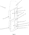
Figure 1 shows in perspective a trawl door of the present invention. -
Figure 2 shows lower cut of the trawl door. -
Figure 3 shows a trawl door with horizontal flap. -
Figure 4 shows an alternative embodiment of the trawl door with slats. - Referring to
Figure 1 there is shown a trawl door (1) of a preferred embodiment of the present invention. It has an upper frame (2) defining a top edge of the door; a lower frame (3) defining a bottom edge of the door; a middle frame (4) defining an intermediate frame positioned between the upper (2) and lower (3) frames thereby establishing an upper and lower section; a lower proximal panel (5) and lower distal panel (6) provided in the lower section and connected between the lower (3) and middle (4) frames as well as an upper proximal panel (7) and an upper distal panel (8) provided in the upper section and connected between the middle (4) and upper (2) frames, said panels (5, 6, 7, 8) being of aerofoil construction and connected to the frames in their respective ends; and flaps (9) mounted below the distal panels (6, 8) and connected to driving units, the flaps (9) adapted to be controlled remotely, when the device is in use being towed through the water; wherein the proximal (5, 7) and distal (6, 8) panels are superimposed and parallel. - Referring to
Figure 2 there is shown a sectional view of the trawl door ofFigure 1 in order to show the hollow distal flap. - Referring to
Figure 3 there is shown a special embodiment of the present invention wherein horizontal flap (12) has been provided on the middle frame. When the flap (12) is angled relative to the frame it will result in a vertical movement of the trawl door. - Vertical movement can also be achieved when the flaps (9) are moved relative to each other.
- As appears from
Figure 4 the spreading device may be provided with movable panels (13, only the upper shown) of aerofoil construction rotatably connected to the frames in their respective ends. Such movable panels are positioned further proximal to the respective proximal panels (7, only the upper shown). These movable panels are adapted to be controlled remotely and further assist the horizontal flaps (12) to control the position of the spreading device in the water.
Claims (11)
- A spreading device, such as a trawl door (1), comprising:an upper frame (2) defining a top edge of the device;a lower frame (3) defining a bottom edge of the device;a middle frame (4) defining an intermediate frame positioned between the upper (2) and lower (3) frames thereby establishing an upper and lower section;a lower proximal panel (5) and lower distal panel (6) provided in the lower section andconnected between the lower (3) and middle (4) frames as well as an upper proximal panel (7) and an upper distal panel (8) provided in the upper section and connected between the middle (4) and upper (2) frames, said panels (5, 6, 7, 8) being of aerofoil construction and connected to the frames in their respective ends; andflaps (9) mounted under the distal panels (6, 8) and connected to driving units, the flaps (9) adapted to be controlled remotely, when the device is in use being towed through the water;characterized in thatthe proximal (5, 7) and distal (6, 8) panels are placed over each other, and wherein the lower distal panel (6) and upper distal panel (8) have a distal surface (6', 8') rendering them hollow, wherein the flaps (9) constitute a part of the distal surface.
- The spreading device of claim 1 further provided with movable panels (13) of aerofoil construction rotatably connected to the frames in their respective ends, said movable panels being positioned further proximal to the respective proximal panels (5, 7), wherein the movable panels (13) are adapted to be remotely controlled.
- The spreading device of claim 1 or 2, wherein the flaps (9) are adapted to move relative to each other.
- The spreading device of any one of the claims 1-3, wherein the flaps (9) are integrated in the most distal parts (6', 8') of the distal panels (6, 8).
- The spreading device of any one the claims 1-4, wherein a lower mesial panel (10) is imposed between the lower proximal (5) and distal (6) panels.
- The spreading device of any one the claims 1-5, wherein an upper mesial panel (11) is imposed between the upper proximal (7) and distal (8) panels.
- The spreading device of claim 5 or 6, wherein the chord of the mesial panel (10, 11) is not parallel with the chords of the proximal (5, 7) and distal panels (6, 8).
- The spreading device of any one the preceding claims, wherein fixation means are provided in the device for pulling after a vessel.
- The spreading device of any one the preceding claims, wherein one or more horizontal flaps (12) are provided on the upper, middle, and/or lower frame.
- The spreading device of any one the preceding claims, wherein the lower distal panel (6) and upper distal panel (8) have a distal surface (6', 8') rendering them hollow, wherein the flaps (9) constitute a part of the distal surface.
- The spreading device of any one the preceding claims, wherein the distal surface (6', 8') of each distal panel (6, 8) is concave.
Applications Claiming Priority (3)
| Application Number | Priority Date | Filing Date | Title |
|---|---|---|---|
| DKPA201570741A DK178860B1 (en) | 2015-11-18 | 2015-11-18 | Trawl door with adjustment means |
| DKPA201670229 | 2016-04-16 | ||
| PCT/DK2016/050360 WO2017084670A1 (en) | 2015-11-18 | 2016-11-10 | Trawl door with adjustment means |
Publications (3)
| Publication Number | Publication Date |
|---|---|
| EP3376858A1 EP3376858A1 (en) | 2018-09-26 |
| EP3376858A4 EP3376858A4 (en) | 2019-06-19 |
| EP3376858B1 true EP3376858B1 (en) | 2022-10-26 |
Family
ID=58717397
Family Applications (1)
| Application Number | Title | Priority Date | Filing Date |
|---|---|---|---|
| EP16865815.1A Active EP3376858B1 (en) | 2015-11-18 | 2016-11-10 | Trawl door with adjustment means |
Country Status (8)
| Country | Link |
|---|---|
| US (1) | US20180325086A1 (en) |
| EP (1) | EP3376858B1 (en) |
| CN (1) | CN108289438B (en) |
| ES (1) | ES2935833T3 (en) |
| LT (1) | LT3376858T (en) |
| PL (1) | PL3376858T3 (en) |
| PT (1) | PT3376858T (en) |
| WO (1) | WO2017084670A1 (en) |
Families Citing this family (10)
| Publication number | Priority date | Publication date | Assignee | Title |
|---|---|---|---|---|
| DK3183959T3 (en) | 2015-12-22 | 2019-04-01 | Volu Ventis Aps | Trawl bucket with flow booster for increased carrying capacity |
| CA2988743A1 (en) * | 2017-12-13 | 2019-06-13 | Fisheries And Marine Institute Of The Memorial University | Multi-kite apparatus for use with bottom trawls |
| NO344107B1 (en) * | 2018-03-02 | 2019-09-09 | Moerenot Fishery As | Trawl door |
| EP3574754A1 (en) * | 2018-05-30 | 2019-12-04 | Volu Ventis ApS | A positional control system for a trawl door |
| GB201811369D0 (en) * | 2018-07-11 | 2018-08-29 | Josafatsson Atli Mar | A spreading device |
| DK180377B1 (en) * | 2019-06-18 | 2021-02-12 | Mld Aps | Trawl bucket with buoyancy adjusting means |
| CN110476904B (en) * | 2019-09-30 | 2021-08-10 | 浙江海洋大学 | Wing-shaped trawl board |
| DK180591B1 (en) * | 2019-11-25 | 2021-09-29 | P/F Vonin | A trawl door with high-lift providing tube element |
| CN110839600B (en) * | 2019-12-06 | 2021-07-16 | 浙江海洋大学 | Trawl board with controllable net shape and using method |
| CN111436404B (en) * | 2020-04-15 | 2022-03-18 | 浙江海洋大学 | Double-cambered surface trawl net plate |
Citations (2)
| Publication number | Priority date | Publication date | Assignee | Title |
|---|---|---|---|---|
| US20080022913A1 (en) * | 2003-03-27 | 2008-01-31 | Rune Toennessen | System for Depth Control of a Marine Deflector |
| US20080271356A1 (en) * | 2004-10-27 | 2008-11-06 | Gudmundur Vigfusson | Higher Efficiency Pelagic Trawl Door Construction Employing Universally Available Materials and Method |
Family Cites Families (16)
| Publication number | Priority date | Publication date | Assignee | Title |
|---|---|---|---|---|
| GB207117A (en) * | 1923-04-05 | 1923-11-22 | Fernand Prosper Constant Lebru | Improvements in otter boards |
| US4180935A (en) * | 1977-08-29 | 1980-01-01 | Massachusetts Institute Of Technology | Hydrofoil trawl door |
| JPH01118660U (en) * | 1988-02-08 | 1989-08-10 | ||
| JPH0488260U (en) * | 1990-12-06 | 1992-07-31 | ||
| AU2005249875B2 (en) * | 2004-06-03 | 2010-11-25 | Singapore Technologies Dynamics Pte Ltd | Method for changing the direction of travel of a watercraft and apparatus therefore |
| WO2006011163A2 (en) * | 2004-07-26 | 2006-02-02 | Candis Ehf. | High speed, increased hydrodynamic efficiency, light-weight molded trawl door and methods for use and manufacture |
| IS8066A (en) * | 2005-10-11 | 2007-04-12 | Hampidjan Hf | Method of producing tow doors |
| CN2834171Y (en) * | 2006-04-07 | 2006-11-08 | 励伟成 | Dragnet web plate |
| IS2635B (en) * | 2007-11-20 | 2010-06-15 | Hampidjan Hf | Improved trawl closure |
| DK2182797T3 (en) * | 2007-07-31 | 2017-07-10 | Thyborøn Skibssmedie As | High-efficiency trawl bucket with high stability |
| NO328745B1 (en) * | 2008-08-11 | 2010-05-03 | Egersund Tral As | Traldor for remote controlled underwater of the active surface area of the traldor. |
| WO2011029958A1 (en) * | 2009-09-14 | 2011-03-17 | Hampidjan Hf | High efficiency, high stability, multi-elevation trawl door and methods |
| US9188691B2 (en) * | 2011-07-05 | 2015-11-17 | Pgs Geophysical As | Towing methods and systems for geophysical surveys |
| IS2837B (en) * | 2011-07-22 | 2013-05-15 | Atli Mar Josafatsson | A trawl door or paravane with remote control adjustment |
| CN103340186B (en) * | 2013-06-13 | 2016-03-02 | 中国水产科学研究院东海水产研究所 | The two cambered surface trawl board of a kind of high aspect ratio and drift along and compare control method |
| ES2813332T3 (en) * | 2013-10-14 | 2021-03-23 | Thyboroen Skibssmedie As | Trailing door |
-
2016
- 2016-11-10 ES ES16865815T patent/ES2935833T3/en active Active
- 2016-11-10 LT LTEPPCT/DK2016/050360T patent/LT3376858T/en unknown
- 2016-11-10 PT PT168658151T patent/PT3376858T/en unknown
- 2016-11-10 US US15/775,987 patent/US20180325086A1/en not_active Abandoned
- 2016-11-10 CN CN201680067367.2A patent/CN108289438B/en active Active
- 2016-11-10 WO PCT/DK2016/050360 patent/WO2017084670A1/en active Application Filing
- 2016-11-10 PL PL16865815.1T patent/PL3376858T3/en unknown
- 2016-11-10 EP EP16865815.1A patent/EP3376858B1/en active Active
Patent Citations (2)
| Publication number | Priority date | Publication date | Assignee | Title |
|---|---|---|---|---|
| US20080022913A1 (en) * | 2003-03-27 | 2008-01-31 | Rune Toennessen | System for Depth Control of a Marine Deflector |
| US20080271356A1 (en) * | 2004-10-27 | 2008-11-06 | Gudmundur Vigfusson | Higher Efficiency Pelagic Trawl Door Construction Employing Universally Available Materials and Method |
Also Published As
| Publication number | Publication date |
|---|---|
| WO2017084670A1 (en) | 2017-05-26 |
| LT3376858T (en) | 2023-02-10 |
| CN108289438B (en) | 2021-07-20 |
| US20180325086A1 (en) | 2018-11-15 |
| ES2935833T3 (en) | 2023-03-10 |
| EP3376858A1 (en) | 2018-09-26 |
| PT3376858T (en) | 2023-01-19 |
| PL3376858T3 (en) | 2023-02-27 |
| CN108289438A (en) | 2018-07-17 |
| EP3376858A4 (en) | 2019-06-19 |
Similar Documents
| Publication | Publication Date | Title |
|---|---|---|
| EP3376858B1 (en) | Trawl door with adjustment means | |
| EP1740453B1 (en) | Watercraft comprising a free-flying maneuverable wind-attacked element as a drive unit | |
| CN103813710B (en) | The trawlnet door adjusted using remotely control or hydrofoil | |
| US20180027784A1 (en) | Rigging configuration for a commercial fishing trawl | |
| AU2016219737B1 (en) | Wake adjustment system for boats | |
| DE102008053495B4 (en) | Muscle powered scuba | |
| DE602005000015T2 (en) | Procedure to improve the landing of an aircraft | |
| WO2018108222A1 (en) | Trawl door with adjustment means | |
| DK178860B1 (en) | Trawl door with adjustment means | |
| CN103340186B (en) | The two cambered surface trawl board of a kind of high aspect ratio and drift along and compare control method | |
| US4858370A (en) | Fishing lure for simulated feeding | |
| EP3041735A1 (en) | Water sport device having a fin | |
| WO2018121829A1 (en) | Trawl door with novel fixation points for pulling after a vessel | |
| CA3143125A1 (en) | Trawl door with lift adjusting means | |
| US8813417B2 (en) | Surf fishing toy | |
| WO1981001990A1 (en) | Body acting as a fin or center board of a sailing boat | |
| RU2292713C2 (en) | Otter board (versions) | |
| DE60007970T2 (en) | FLOATING BODIES FOR FAST WATER VEHICLES | |
| CN203439252U (en) | Direction adjuster for kayak | |
| DE3404588A1 (en) | Device for stabilising the water position of sailing boats | |
| DE19752170A1 (en) | Lift providing construction for multi keel boat e.g. catamaran or trimaran | |
| AU2016203389B1 (en) | Apparatus for generating a wave | |
| DE102016007018A1 (en) | Traction device for water sports or winter sports | |
| US20160264241A1 (en) | Flyable sailboat | |
| DE102010049666B3 (en) | Fishing rod accessory equipment for use during fishing in e.g. flowing water, has floatation chamber fastened at fishing line by cord stopper, where direction of drift movement of chamber is reversed by position change of chamber |
Legal Events
| Date | Code | Title | Description |
|---|---|---|---|
| STAA | Information on the status of an ep patent application or granted ep patent |
Free format text: STATUS: THE INTERNATIONAL PUBLICATION HAS BEEN MADE |
|
| PUAI | Public reference made under article 153(3) epc to a published international application that has entered the european phase |
Free format text: ORIGINAL CODE: 0009012 |
|
| STAA | Information on the status of an ep patent application or granted ep patent |
Free format text: STATUS: REQUEST FOR EXAMINATION WAS MADE |
|
| 17P | Request for examination filed |
Effective date: 20180613 |
|
| AK | Designated contracting states |
Kind code of ref document: A1 Designated state(s): AL AT BE BG CH CY CZ DE DK EE ES FI FR GB GR HR HU IE IS IT LI LT LU LV MC MK MT NL NO PL PT RO RS SE SI SK SM TR |
|
| AX | Request for extension of the european patent |
Extension state: BA ME |
|
| DAV | Request for validation of the european patent (deleted) | ||
| DAX | Request for extension of the european patent (deleted) | ||
| A4 | Supplementary search report drawn up and despatched |
Effective date: 20190520 |
|
| RIC1 | Information provided on ipc code assigned before grant |
Ipc: A01K 73/045 20060101AFI20190514BHEP |
|
| STAA | Information on the status of an ep patent application or granted ep patent |
Free format text: STATUS: EXAMINATION IS IN PROGRESS |
|
| 17Q | First examination report despatched |
Effective date: 20200602 |
|
| STAA | Information on the status of an ep patent application or granted ep patent |
Free format text: STATUS: EXAMINATION IS IN PROGRESS |
|
| GRAP | Despatch of communication of intention to grant a patent |
Free format text: ORIGINAL CODE: EPIDOSNIGR1 |
|
| STAA | Information on the status of an ep patent application or granted ep patent |
Free format text: STATUS: GRANT OF PATENT IS INTENDED |
|
| INTG | Intention to grant announced |
Effective date: 20220516 |
|
| GRAS | Grant fee paid |
Free format text: ORIGINAL CODE: EPIDOSNIGR3 |
|
| GRAA | (expected) grant |
Free format text: ORIGINAL CODE: 0009210 |
|
| STAA | Information on the status of an ep patent application or granted ep patent |
Free format text: STATUS: THE PATENT HAS BEEN GRANTED |
|
| AK | Designated contracting states |
Kind code of ref document: B1 Designated state(s): AL AT BE BG CH CY CZ DE DK EE ES FI FR GB GR HR HU IE IS IT LI LT LU LV MC MK MT NL NO PL PT RO RS SE SI SK SM TR |
|
| REG | Reference to a national code |
Ref country code: GB Ref legal event code: FG4D |
|
| REG | Reference to a national code |
Ref country code: CH Ref legal event code: EP |
|
| REG | Reference to a national code |
Ref country code: DE Ref legal event code: R096 Ref document number: 602016075964 Country of ref document: DE |
|
| REG | Reference to a national code |
Ref country code: AT Ref legal event code: REF Ref document number: 1526396 Country of ref document: AT Kind code of ref document: T Effective date: 20221115 |
|
| REG | Reference to a national code |
Ref country code: IE Ref legal event code: FG4D |
|
| REG | Reference to a national code |
Ref country code: NL Ref legal event code: FP |
|
| REG | Reference to a national code |
Ref country code: PT Ref legal event code: SC4A Ref document number: 3376858 Country of ref document: PT Date of ref document: 20230119 Kind code of ref document: T Free format text: AVAILABILITY OF NATIONAL TRANSLATION Effective date: 20230113 |
|
| REG | Reference to a national code |
Ref country code: NO Ref legal event code: T2 Effective date: 20221026 |
|
| REG | Reference to a national code |
Ref country code: ES Ref legal event code: FG2A Ref document number: 2935833 Country of ref document: ES Kind code of ref document: T3 Effective date: 20230310 |
|
| REG | Reference to a national code |
Ref country code: AT Ref legal event code: MK05 Ref document number: 1526396 Country of ref document: AT Kind code of ref document: T Effective date: 20221026 |
|
| PG25 | Lapsed in a contracting state [announced via postgrant information from national office to epo] |
Ref country code: SE Free format text: LAPSE BECAUSE OF FAILURE TO SUBMIT A TRANSLATION OF THE DESCRIPTION OR TO PAY THE FEE WITHIN THE PRESCRIBED TIME-LIMIT Effective date: 20221026 Ref country code: FI Free format text: LAPSE BECAUSE OF FAILURE TO SUBMIT A TRANSLATION OF THE DESCRIPTION OR TO PAY THE FEE WITHIN THE PRESCRIBED TIME-LIMIT Effective date: 20221026 Ref country code: AT Free format text: LAPSE BECAUSE OF FAILURE TO SUBMIT A TRANSLATION OF THE DESCRIPTION OR TO PAY THE FEE WITHIN THE PRESCRIBED TIME-LIMIT Effective date: 20221026 |
|
| PG25 | Lapsed in a contracting state [announced via postgrant information from national office to epo] |
Ref country code: RS Free format text: LAPSE BECAUSE OF FAILURE TO SUBMIT A TRANSLATION OF THE DESCRIPTION OR TO PAY THE FEE WITHIN THE PRESCRIBED TIME-LIMIT Effective date: 20221026 Ref country code: HR Free format text: LAPSE BECAUSE OF FAILURE TO SUBMIT A TRANSLATION OF THE DESCRIPTION OR TO PAY THE FEE WITHIN THE PRESCRIBED TIME-LIMIT Effective date: 20221026 Ref country code: GR Free format text: LAPSE BECAUSE OF FAILURE TO SUBMIT A TRANSLATION OF THE DESCRIPTION OR TO PAY THE FEE WITHIN THE PRESCRIBED TIME-LIMIT Effective date: 20230127 |
|
| PGFP | Annual fee paid to national office [announced via postgrant information from national office to epo] |
Ref country code: PL Payment date: 20230201 Year of fee payment: 7 |
|
| REG | Reference to a national code |
Ref country code: DE Ref legal event code: R119 Ref document number: 602016075964 Country of ref document: DE |
|
| REG | Reference to a national code |
Ref country code: CH Ref legal event code: PL |
|
| REG | Reference to a national code |
Ref country code: BE Ref legal event code: MM Effective date: 20221130 |
|
| PG25 | Lapsed in a contracting state [announced via postgrant information from national office to epo] |
Ref country code: SM Free format text: LAPSE BECAUSE OF FAILURE TO SUBMIT A TRANSLATION OF THE DESCRIPTION OR TO PAY THE FEE WITHIN THE PRESCRIBED TIME-LIMIT Effective date: 20221026 Ref country code: RO Free format text: LAPSE BECAUSE OF FAILURE TO SUBMIT A TRANSLATION OF THE DESCRIPTION OR TO PAY THE FEE WITHIN THE PRESCRIBED TIME-LIMIT Effective date: 20221026 Ref country code: MC Free format text: LAPSE BECAUSE OF FAILURE TO SUBMIT A TRANSLATION OF THE DESCRIPTION OR TO PAY THE FEE WITHIN THE PRESCRIBED TIME-LIMIT Effective date: 20221026 Ref country code: LI Free format text: LAPSE BECAUSE OF NON-PAYMENT OF DUE FEES Effective date: 20221130 Ref country code: EE Free format text: LAPSE BECAUSE OF FAILURE TO SUBMIT A TRANSLATION OF THE DESCRIPTION OR TO PAY THE FEE WITHIN THE PRESCRIBED TIME-LIMIT Effective date: 20221026 Ref country code: DK Free format text: LAPSE BECAUSE OF FAILURE TO SUBMIT A TRANSLATION OF THE DESCRIPTION OR TO PAY THE FEE WITHIN THE PRESCRIBED TIME-LIMIT Effective date: 20221026 Ref country code: CZ Free format text: LAPSE BECAUSE OF FAILURE TO SUBMIT A TRANSLATION OF THE DESCRIPTION OR TO PAY THE FEE WITHIN THE PRESCRIBED TIME-LIMIT Effective date: 20221026 Ref country code: CH Free format text: LAPSE BECAUSE OF NON-PAYMENT OF DUE FEES Effective date: 20221130 |
|
| PG25 | Lapsed in a contracting state [announced via postgrant information from national office to epo] |
Ref country code: SK Free format text: LAPSE BECAUSE OF FAILURE TO SUBMIT A TRANSLATION OF THE DESCRIPTION OR TO PAY THE FEE WITHIN THE PRESCRIBED TIME-LIMIT Effective date: 20221026 Ref country code: LU Free format text: LAPSE BECAUSE OF NON-PAYMENT OF DUE FEES Effective date: 20221110 Ref country code: AL Free format text: LAPSE BECAUSE OF FAILURE TO SUBMIT A TRANSLATION OF THE DESCRIPTION OR TO PAY THE FEE WITHIN THE PRESCRIBED TIME-LIMIT Effective date: 20221026 |
|
| PLBE | No opposition filed within time limit |
Free format text: ORIGINAL CODE: 0009261 |
|
| STAA | Information on the status of an ep patent application or granted ep patent |
Free format text: STATUS: NO OPPOSITION FILED WITHIN TIME LIMIT |
|
| 26N | No opposition filed |
Effective date: 20230727 |
|
| PG25 | Lapsed in a contracting state [announced via postgrant information from national office to epo] |
Ref country code: DE Free format text: LAPSE BECAUSE OF NON-PAYMENT OF DUE FEES Effective date: 20230601 |
|
| PG25 | Lapsed in a contracting state [announced via postgrant information from national office to epo] |
Ref country code: SI Free format text: LAPSE BECAUSE OF FAILURE TO SUBMIT A TRANSLATION OF THE DESCRIPTION OR TO PAY THE FEE WITHIN THE PRESCRIBED TIME-LIMIT Effective date: 20221026 Ref country code: BE Free format text: LAPSE BECAUSE OF NON-PAYMENT OF DUE FEES Effective date: 20221130 |
|
| PGFP | Annual fee paid to national office [announced via postgrant information from national office to epo] |
Ref country code: NL Payment date: 20231120 Year of fee payment: 8 |
|
| PGFP | Annual fee paid to national office [announced via postgrant information from national office to epo] |
Ref country code: GB Payment date: 20231120 Year of fee payment: 8 |
|
| PGFP | Annual fee paid to national office [announced via postgrant information from national office to epo] |
Ref country code: ES Payment date: 20231213 Year of fee payment: 8 |
|
| PGFP | Annual fee paid to national office [announced via postgrant information from national office to epo] |
Ref country code: IS Payment date: 20231120 Year of fee payment: 8 |
|
| PGFP | Annual fee paid to national office [announced via postgrant information from national office to epo] |
Ref country code: TR Payment date: 20231103 Year of fee payment: 8 Ref country code: PT Payment date: 20231102 Year of fee payment: 8 Ref country code: NO Payment date: 20231121 Year of fee payment: 8 Ref country code: LV Payment date: 20231121 Year of fee payment: 8 Ref country code: LT Payment date: 20231031 Year of fee payment: 8 Ref country code: IT Payment date: 20231120 Year of fee payment: 8 Ref country code: IE Payment date: 20231121 Year of fee payment: 8 Ref country code: FR Payment date: 20231115 Year of fee payment: 8 |
|
| PGFP | Annual fee paid to national office [announced via postgrant information from national office to epo] |
Ref country code: PL Payment date: 20231030 Year of fee payment: 8 |
|
| PG25 | Lapsed in a contracting state [announced via postgrant information from national office to epo] |
Ref country code: HU Free format text: LAPSE BECAUSE OF FAILURE TO SUBMIT A TRANSLATION OF THE DESCRIPTION OR TO PAY THE FEE WITHIN THE PRESCRIBED TIME-LIMIT; INVALID AB INITIO Effective date: 20161110 |