EP3376742A1 - Enceinte de décoration, ensemble d'entrée et terminal - Google Patents
Enceinte de décoration, ensemble d'entrée et terminal Download PDFInfo
- Publication number
- EP3376742A1 EP3376742A1 EP18171597.0A EP18171597A EP3376742A1 EP 3376742 A1 EP3376742 A1 EP 3376742A1 EP 18171597 A EP18171597 A EP 18171597A EP 3376742 A1 EP3376742 A1 EP 3376742A1
- Authority
- EP
- European Patent Office
- Prior art keywords
- decoration
- protrusion
- input assembly
- decoration enclosure
- enclosure
- Prior art date
- Legal status (The legal status is an assumption and is not a legal conclusion. Google has not performed a legal analysis and makes no representation as to the accuracy of the status listed.)
- Granted
Links
Images


Classifications
-
- G—PHYSICS
- G06—COMPUTING; CALCULATING OR COUNTING
- G06F—ELECTRIC DIGITAL DATA PROCESSING
- G06F3/00—Input arrangements for transferring data to be processed into a form capable of being handled by the computer; Output arrangements for transferring data from processing unit to output unit, e.g. interface arrangements
- G06F3/01—Input arrangements or combined input and output arrangements for interaction between user and computer
- G06F3/03—Arrangements for converting the position or the displacement of a member into a coded form
- G06F3/041—Digitisers, e.g. for touch screens or touch pads, characterised by the transducing means
-
- B—PERFORMING OPERATIONS; TRANSPORTING
- B29—WORKING OF PLASTICS; WORKING OF SUBSTANCES IN A PLASTIC STATE IN GENERAL
- B29C—SHAPING OR JOINING OF PLASTICS; SHAPING OF MATERIAL IN A PLASTIC STATE, NOT OTHERWISE PROVIDED FOR; AFTER-TREATMENT OF THE SHAPED PRODUCTS, e.g. REPAIRING
- B29C45/00—Injection moulding, i.e. forcing the required volume of moulding material through a nozzle into a closed mould; Apparatus therefor
- B29C45/16—Making multilayered or multicoloured articles
- B29C45/1657—Making multilayered or multicoloured articles using means for adhering or bonding the layers or parts to each other
-
- G—PHYSICS
- G06—COMPUTING; CALCULATING OR COUNTING
- G06F—ELECTRIC DIGITAL DATA PROCESSING
- G06F1/00—Details not covered by groups G06F3/00 - G06F13/00 and G06F21/00
- G06F1/16—Constructional details or arrangements
- G06F1/1613—Constructional details or arrangements for portable computers
- G06F1/1633—Constructional details or arrangements of portable computers not specific to the type of enclosures covered by groups G06F1/1615 - G06F1/1626
- G06F1/1684—Constructional details or arrangements related to integrated I/O peripherals not covered by groups G06F1/1635 - G06F1/1675
-
- G—PHYSICS
- G06—COMPUTING; CALCULATING OR COUNTING
- G06F—ELECTRIC DIGITAL DATA PROCESSING
- G06F21/00—Security arrangements for protecting computers, components thereof, programs or data against unauthorised activity
- G06F21/30—Authentication, i.e. establishing the identity or authorisation of security principals
- G06F21/31—User authentication
- G06F21/32—User authentication using biometric data, e.g. fingerprints, iris scans or voiceprints
-
- G—PHYSICS
- G06—COMPUTING; CALCULATING OR COUNTING
- G06F—ELECTRIC DIGITAL DATA PROCESSING
- G06F21/00—Security arrangements for protecting computers, components thereof, programs or data against unauthorised activity
- G06F21/70—Protecting specific internal or peripheral components, in which the protection of a component leads to protection of the entire computer
- G06F21/82—Protecting input, output or interconnection devices
- G06F21/83—Protecting input, output or interconnection devices input devices, e.g. keyboards, mice or controllers thereof
-
- G—PHYSICS
- G06—COMPUTING; CALCULATING OR COUNTING
- G06V—IMAGE OR VIDEO RECOGNITION OR UNDERSTANDING
- G06V40/00—Recognition of biometric, human-related or animal-related patterns in image or video data
- G06V40/10—Human or animal bodies, e.g. vehicle occupants or pedestrians; Body parts, e.g. hands
- G06V40/12—Fingerprints or palmprints
-
- H—ELECTRICITY
- H01—ELECTRIC ELEMENTS
- H01L—SEMICONDUCTOR DEVICES NOT COVERED BY CLASS H10
- H01L21/00—Processes or apparatus adapted for the manufacture or treatment of semiconductor or solid state devices or of parts thereof
- H01L21/02—Manufacture or treatment of semiconductor devices or of parts thereof
- H01L21/04—Manufacture or treatment of semiconductor devices or of parts thereof the devices having at least one potential-jump barrier or surface barrier, e.g. PN junction, depletion layer or carrier concentration layer
- H01L21/50—Assembly of semiconductor devices using processes or apparatus not provided for in a single one of the subgroups H01L21/06 - H01L21/326, e.g. sealing of a cap to a base of a container
- H01L21/56—Encapsulations, e.g. encapsulation layers, coatings
-
- H—ELECTRICITY
- H04—ELECTRIC COMMUNICATION TECHNIQUE
- H04M—TELEPHONIC COMMUNICATION
- H04M1/00—Substation equipment, e.g. for use by subscribers
- H04M1/02—Constructional features of telephone sets
- H04M1/0202—Portable telephone sets, e.g. cordless phones, mobile phones or bar type handsets
- H04M1/026—Details of the structure or mounting of specific components
-
- H—ELECTRICITY
- H04—ELECTRIC COMMUNICATION TECHNIQUE
- H04M—TELEPHONIC COMMUNICATION
- H04M1/00—Substation equipment, e.g. for use by subscribers
- H04M1/02—Constructional features of telephone sets
- H04M1/0202—Portable telephone sets, e.g. cordless phones, mobile phones or bar type handsets
- H04M1/0279—Improving the user comfort or ergonomics
- H04M1/0283—Improving the user comfort or ergonomics for providing a decorative aspect, e.g. customization of casings, exchangeable faceplate
-
- H—ELECTRICITY
- H03—ELECTRONIC CIRCUITRY
- H03K—PULSE TECHNIQUE
- H03K17/00—Electronic switching or gating, i.e. not by contact-making and –breaking
- H03K17/94—Electronic switching or gating, i.e. not by contact-making and –breaking characterised by the way in which the control signals are generated
- H03K17/96—Touch switches
Definitions
- the present disclosure relates to a field of terminals, and particularly, to a decoration enclosure, an input assembly and a terminal.
- some mobile phones include a fingerprint chip package structure and a decoration enclosure, and the fingerprint chip package structure is received in the decoration enclosure, so that the mobile phone has a good appearance.
- a position where the fingerprint chip package structure is received in the decoration enclosure is difficult to be determined, thus resulting in a low assembling efficiency when disposing the fingerprint chip package structure in the decoration enclosure.
- the present disclosure aims to solve at least one of the technical problems above in the related art. Accordingly, the present disclosure provides a decoration enclosure, an input assembly and a terminal.
- a decoration enclosure for decorating a fingerprint identification structure of an input assembly.
- the decoration enclosure includes a decoration ring and a support rim supporting the fingerprint identification structure.
- the support rim extends inwards from an inner wall of the decoration ring and supports the fingerprint identification structure.
- the decoration enclosure includes a flange extending outwards from an outer wall of the decoration ring.
- the flange includes a first protrusion and a second protrusion coupled to the first protrusion, and the first protrusion includes a first portion and a second portion.
- the second portion is coupled to the first portion and the second protrusion, and the second portion protrudes beyond the first portion and the second protrusion.
- a top surface of the first protrusion is flush with a top surface of the second protrusion and a thickness of the first portion is larger than a thickness of the second protrusion.
- the support rim of the decoration enclosure may support and position a fingerprint identification structure, so as to improve an assembling efficiency of the fingerprint identification structure and the decoration enclosure.
- the flange increases a connecting area between the decoration enclosure and a touch panel of the terminal, and hence improves the reliability of fixedly connecting the decoration enclosure with the touch pane.
- the flange is provided to improve the assembling efficiency of the input assembly and to reduce the production cost of the input assembly.
- an area ratio of a display region to the touch panel will not be reduced, and thus the appearance of the terminal will not be affected, on the premise that these above significant effects are maintained.
- the support rim defines a hole therein to receive at least part of the fingerprint identification structure.
- the hole is configured to have a rounded rectangle shape
- a side wall surrounding the hole has a groove in an axial direction of the hole, and the groove is in communication with the hole.
- the support rim is perpendicular to the inner wall of the decoration ring.
- the decoration ring includes a bottom surface connected with the inner wall, and a lower surface of the support rim is flush with the bottom surface.
- the decoration ring includes a top wall connected with the inner wall, and the top wall includes a guiding surface facing towards an interior of the decoration enclosure.
- the decoration ring has a long circle shape
- the outer wall of the decoration ring includes two straight segments in parallel and two curved segments each coupled to the two straight segments, the first portion is provided to one of the two straight segments, and the second portion is provided to each curved segment.
- an input assembly for a terminal.
- the input assembly includes a fingerprint identification structure and a decoration enclosure coupled to the fingerprint identification structure and configured to decorate the fingerprint identification structure.
- the decoration enclosure is configured as a decoration enclosure according to any one of above embodiments.
- the support rim of the decoration enclosure may support and position the fingerprint identification structure, so as to improve an assembling efficiency of the fingerprint identification structure and the decoration enclosure.
- the flange increases a connecting area between the decoration enclosure and a touch panel of the terminal, and hence improves the reliability of fixedly connecting the decoration enclosure with the touch pane.
- the flange is provided to improve the assembling efficiency of the input assembly and to reduce the production cost of the input assembly.
- an area ratio of a display region to the touch panel will not be reduced, and thus the appearance of the terminal will not be affected, on the premise that these above significant effects are maintained.
- the fingerprint identification structure includes: a package body having a bottom surface and a lateral surface connected to the bottom surface, in which the package body defines at least one recessed portion at a junction of the bottom surface and the lateral surface; and a fingerprint identification chip received in the package body.
- the recessed portion includes a first surface and a second surface connected to the first surface, and the first surface is perpendicular to the second surface.
- the recessed portion has a transition fillet at a junction of the first surface and the second surface.
- the at least one recessed portion includes one recessed portion.
- the one recessed portion is configured to have an annular shape and surround the junction of the bottom surface and the lateral surface.
- the at least one recessed portion includes a plurality of recessed portions spaced apart from one another along a circumferential direction of the junction of the bottom surface and the lateral surface.
- a terminal includes a screen, a flexible screen circuit board coupled to the screen, a touch panel located above the screen and having a mounting hole, and an input assembly mounted in the mounting hole.
- the input assembly is configured as an input assembly according to any one of above embodiments.
- the support rim of the decoration enclosure may support and position the fingerprint identification structure, so as to improve an assembling efficiency of the fingerprint identification structure and the decoration enclosure.
- the flange increases a connecting area between the decoration enclosure and a touch panel of the terminal, and hence improves the reliability of fixedly connecting the decoration enclosure with the touch pane.
- the flange is provided to improve the assembling efficiency of the input assembly and to reduce the production cost of the input assembly.
- an area ratio of a display region to the touch panel will not be reduced, and thus the appearance of the terminal will not be affected, on the premise that these above significant effects are maintained.
- the terms “mounted”, “connected”, “coupled”, “fixed” and the like are used broadly, and may be, for example, fixed connections, detachable connections, or integral connections; may also be mechanical or electrical connections; may also be direct connections or indirect connections via intervening structures; may also be inner communications of two elements, which can be understood by those skilled in the art according to specific situations.
- a structure in which a first feature is "on" or “below” a second feature may include an embodiment in which the first feature is in direct contact with the second feature, and may also include an embodiment in which the first feature and the second feature are not in direct contact with each other, but are contacted via an additional feature formed therebetween.
- a first feature "on”, “above” or “on top of' a second feature may include an embodiment in which the first feature is right or obliquely “on”, “above” or “on top of' the second feature, or just means that the first feature is at a height higher than that of the second feature; while a first feature "below”, “under” or “on bottom of' a second feature may include an embodiment in which the first feature is right or obliquely “below”, “under” or “on bottom of' the second feature, or just means that the first feature is at a height lower than that of the second feature.
- an input assembly 100 includes a touch panel 10, a decoration enclosure 20 and a fingerprint identification structure decorated by the decoration enclosure 20.
- the fingerprint identification structure can be a fingerprint chip package structure 30 or other component with a function of fingerprint identification.
- the input assembly 100 can be applied to a terminal 1000, and the terminal 1000 can be configured as an electronic device such as a mobile phone or a tablet. It can be understood that, the terminal 1000 includes but is not limited to examples in the present embodiment. In some embodiments, the terminal 1000 further includes a screen 80 configured to display content and a flexible screen circuit board 50 coupled to the screen 80.
- the touch panel 10 is located above the screen 80, and includes an upper surface 12 and a lower surface 14, as illustrated in Fig. 2 .
- the upper surface 12 is opposite to the lower surface 14.
- the upper surface 12 of the touch panel 10 is a facade of the input assembly 100, facing to a user. The user can make gesture operations (for example clicking or sliding) on the upper surface 12, so as to control the terminal 1000 to achieve corresponding functions.
- the touch panel 10 can be made of light-transparent materials, such as glasses, ceramics or sapphires. As the touch panel 10 is configured as an input part of the terminal 1000, the touch panel 10 always suffers contacts, such as impacts or scratches. For example, when the user puts the terminal 1000 into his/her pocket, the touch panel 10 can be scratched and damaged by keys in the pocket of the user.
- the touch panel 10 can be made of materials having high hardness, for example the above-mentioned sapphires. Certainly, a protecting cover plate can be attached on the upper surface 12 of the touch panel 10, so as to prevent the touch panel 10 from being scratched.
- the touch panel 10 includes a display region 15 intended for the user to view the content displayed in the screen 80 and a non-display region 16 for receiving the fingerprint identification structure.
- a middle region of the touch panel 10 is configured as the display region 15, and the non-display region 16 is arranged at a periphery of the display region 15.
- the non-display region 16 is located at a top side or a bottom side of the display region 15.
- the touch panel 10 is made of the light-transparent materials, thus, the user can view content displayed in the screen 80 of the terminal 1000 through the display region 15.
- ink can be sprayed on a lower surface 14 of the non-display region 16.
- the ink can have a color such as white, black or blue, and so on. A specific color can be set according to actual requirements.
- the ink can not only satisfy requirements of the user for terminals 1000 having various colors, but also shield structures inside the terminal 1000 so as to reach an effect of beautifying the terminal 1000.
- a shape of the touch panel 10 can be designed specifically according to a shape of the terminal 1000, for example being configured as a rounded rectangle.
- the touch panel 10 has a mounting hole 17.
- the mounting hole 17 is configured as a through hole running through the upper surface 12 and the lower surface 14. In other embodiments, the mounting hole 17 can be configured a blind hole formed in the lower surface 14.
- the mounting hole 17 is configured to have a long circle shape.
- the mounting hole 17 can have various shapes according to specific requirements, for example a round or oval shape. Therefore, examples of the shape of the mounting hole 17 in the present embodiment cannot be construed to limit the present disclosure.
- the decoration enclosure 20 is fitted in the mounting hole 17 and fixedly coupled to the touch panel 10.
- the fingerprint chip package structure 30 is accommodated in the decoration enclosure 20 and fixedly coupled to the decoration enclosure 20.
- a receiver of the terminal 1000 is disposed in a top region of the terminal 1000. Therefore, for preventing the mounting hole 17 from having an interference with the receiver, in some embodiments, the mounting hole 17 is provided in a bottom region of the touch panel 10, thereby providing a relatively large design space for the mounting hole 17. Furthermore, the mounting hole 17 is provided in the non-display region 16 of the touch panel 10.
- the mounting hole 17 is defined in the middle of the bottom region of the touch panel 10, so that the touch panel 10 presents an approximately symmetrical structure.
- the terminal 1000 has a better appearance and is easy to be operated by the user.
- the decoration enclosure 20 can be mounted into the mounting hole 17 from underneath of the touch panel 10 firstly, and then an adhesive is dispensed in a gap between an inner wall of the mounting hole 17 and the decoration enclosure 20, so that the decoration enclosure 20 is fixedly coupled to the touch panel 10.
- the fingerprint chip package structure 30 is mounted into the decoration enclosure 20 from above of the touch panel 10, and the fingerprint chip package structure 30 is fixedly coupled to the decoration enclosure 20 through the adhesive.
- the fingerprint chip package structure 30 can be mounted into the decoration enclosure 20 firstly, then the decoration enclosure 20 carried with the fingerprint chip package structure 30 can be mounted into the mounting hole 17, and the adhesive can be used to adhere and fix the decoration enclosure 20 to the touch panel 10.
- the decoration enclosure 20 includes a decoration ring 21 and a support rim 22.
- the support rim 22 is configured to support the fingerprint chip.
- the support rim 22 extends inwards from an inner wall 211 of the decoration ring 21.
- the support rim 22 of the decoration enclosure 20 can support and position the fingerprint chip package structure 30, thereby improving an assembling efficiency of the fingerprint chip package structure 30 and the decoration enclosure 20.
- the fingerprint chip package structure 30 is supported on the support rim 22.
- the fingerprint chip package structure 30 can be pressed from top to down. If the fingerprint chip package structure 30 cannot be moved any more, it indicates that the fingerprint chip package structure 30 abuts against the support rim 22 and is mounted to a preset location.
- the decoration ring 21 defines an accommodating hole 212, and the support rim 22 is located in the accommodating hole 212.
- the accommodating hole 212 can be configured to have a straight cylinder shape, or that is to say, the inner wall 211 is configured to be straight, so that the fingerprint chip package structure 30 is easy to be mounted in the accommodating hole 212 rapidly.
- the accommodating hole 212 and the support rim 22 can be formed by removing materials from the parts through cutting process, or can be formed by casting.
- materials of the decoration enclosure 20 can be metal, for example stainless steel materials, thereby satisfying strength requirements of the decoration enclosure 20 as well as providing a corrosion resistance and improving a service life of the decoration enclosure 20.
- the decoration enclosure 20 can also be made of other materials, such as plastics.
- the fingerprint chip package structure 30 is accommodated in the decoration ring 21 and supported on the support rim 22.
- the support rim 22 is perpendicular to the inner wall 211 of the decoration ring 21.
- the support rim 22 is easy to be formed, thereby reducing a production cost of the decoration ring 21.
- the support rim 22 is located in a horizontal position, and the inner wall 211 of the decoration ring 21 is located in a vertical position, so that a surface of the fingerprint chip package structure 30 fitted with the support rim 22 is a horizontal surface, thereby simplifying a structure of the fingerprint chip package structure 30 supported on the support rim 22.
- the decoration ring 21 includes a first bottom surface 213 connected to the inner wall 211, and a lower surface 221 of the support rim 22 is flush with the first bottom surface 213.
- the decoration ring 21 having an arrangement described above has a relatively large accommodating space, so as to ensure that the fingerprint chip package structure 30 can be accommodated in the decoration ring 21.
- a height of the decoration ring 21 is relatively small, thus reducing a height of the input assembly 100, thereby providing a design basis for reducing a thickness of the terminal 1000.
- the decoration ring 21 includes a top wall 214.
- the top wall 214 is connected to the inner wall 211.
- the top wall 214 includes a guiding surface 2142 facing towards an interior of the decoration enclosure 20.
- the guiding surface 2142 can guide a finger of the user to enter the decoration ring 21 smoothly, so as to perform fingerprint identification operations, thereby improving an accuracy of the user performing the fingerprint identification operations. Furthermore, the guiding surface 2142 can be coated with a shiny metal layer (such as a chromium layer), so that the decoration ring 21 has a better appearance.
- a shiny metal layer such as a chromium layer
- the guiding surface 2142 can be configured as an annular surface, thereby facilitating the user to place the finger thereof in the decoration ring 21 from respective directions, so as to press the fingerprint chip package structure 30 and perform the fingerprint identification operations.
- the support rim 22 has a hole 222 therein.
- the hole 222 contributes to a routing layout of a flexible fingerprint circuit board 40 coupled to the fingerprint chip package structure 30.
- the flexible fingerprint circuit board 40 can run through the hole 222 so as to be coupled to the fingerprint chip package structure 30 (as illustrated in Fig. 2 ).
- the flexible fingerprint circuit board 40 is configured to transmit a fingerprint signal between the fingerprint chip package structure 30 and a mainboard of the terminal 1000.
- the hole 222 is configured to have a rounded rectangle shape.
- a side wall 2221 surrounding the hole 222 has a groove 2222 along an axial direction (i.e. a left-right direction illustrated in Fig. 1 ) of the hole 222, and the groove 2222 is communicated with the hole 222.
- the flexible fingerprint circuit board 40 after being coupled to the fingerprint chip package structure 30, the flexible fingerprint circuit board 40 firstly extends in a direction towards the groove 2222, then is bent and extends in an opposite direction running away from the groove 2222. Therefore, the groove 2222 can prevent the flexible fingerprint circuit board 40 from producing an interference with the side wall 2221, thereby facilitating wiring of the flexible fingerprint circuit board 40.
- the decoration enclosure 20 includes a flange 23 extending outwards from an outer wall 215 of the decoration ring 21.
- the flange 23 can abut against the lower surface 14 of the touch panel 10, thereby increasing a connecting area between the decoration enclosure 20 and the touch panel 10, and improving the reliability of fixedly connecting the decoration enclosure 20 with the touch panel 10.
- the flange 23 is provided to improve the assembling efficiency of the input assembly 100 and to reduce the production cost of the input assembly 100.
- a sealing sheet can be provided between the flange 23 and the lower surface 14, so as to prevent water from entering the terminal 1000 through a gap between the decoration enclosure 20 and the mounting hole 17, thereby improving a water resistance effect of the terminal 1000.
- the flange 23 and the decoration ring 21 are integrally formed. However, in embodiments illustrated in Fig. 6 and Fig. 7 , the flange 23 and the decoration ring 21 are separately formed.
- the decoration ring 21 includes a muff-coupling portion 24, and the muff-coupling portion 24 is connected to the support rim 22.
- the flange 23 is fitted over the muff-coupling portion 24. Since the flange 23 and the decoration ring 21 are separately formed, production difficulties of the decoration enclosure 20 can be reduced, so that uniformity of each decoration enclosure 20 can be improved when the decoration enclosure 20 is put into mass production.
- the muff-coupling portion 24 can have a through hole 24a through which the flexible fingerprint circuit board 40 can run.
- the muff-coupling portion 24 includes a connecting rim 241 and a bearing plate 242.
- the connecting rim 241 is connected to the support rim 22 and the bearing plate 242.
- the connecting rim 241 is substantially perpendicular to the support rim 22.
- the bearing plate 242 is substantially perpendicular to the connecting rim 241.
- the connecting rim 241 has the through hole 24a therein.
- the muff-coupling portion 24 is hollow so as to accommodate a part or a whole of the fingerprint chip package structure 30.
- the fingerprint chip package structure 30 can be supported on the bearing plate 242.
- the flange 23 is perpendicular to the outer wall 215 of the decoration ring 21.
- the manufacturing process of the decoration enclosure 20 is easy, and a contact area of the decoration enclosure 20 and the touch panel 10 can also be improved, in which the contact area is used for connection between the decoration enclosure 20 and the touch panel 10.
- the flange 23 includes a first protrusion 231 and a second protrusion 232 coupled to the first protrusion 231.
- the first protrusion 231 includes a first portion 2311 and a second portion 2312.
- the second portion 2312 is coupled to the first portion 2311 and the second protrusion 232.
- the second portion 2312 protrudes beyond the first portion 2311 and the second protrusion 232, that is, an outer edge of the second portion 2312 has a larger distance from the outer wall 215 of the decoration ring 21 than outer edges of the first portion 2311 and the second protrusion 232.
- the first portion 2311 and the second protrusion 232 extend along a traverse direction of the touch panel 10 and the second portion 2312 extends along a longitudinal direction of the touch panel 10.
- the second portion 2312 can protrude beyond the first portion 2311 and the second protrusion 232, so as to increase a connecting area of the flange 23 and the touch panel 10.
- widths of the first portion 2311 and the second protrusion 232 are relatively small, thereby avoiding a longitudinal size of the non-display region 16 of the touch panel 10 from being increased due to the widths of the first portion 2311 and the second protrusion 232, such that an area ratio of the display region 15 to the touch panel 10 will not be reduced, and thus the appearance of the terminal 1000 will not be affected.
- a top surface 231a of the first protrusion 231 is flush with a top surface 232a of the second protrusion 232, and a thickness of the first portion 2311 is larger than a thickness of the second protrusion 232.
- the second protrusion 232 when the decoration enclosure 20 is mounted in the mounting hole 17, the second protrusion 232 is closer to the display region 15, compared to the first portion 2311. Or, that is to say, the first portion 2311 is away from the display region 15, and the second protrusion 232 is close to the display region 15.
- the second protrusion 232 will not have an interference with other parts close to the display region 15 due to the small thickness of the second protrusion 232 (as illustrated in Fig. 2 ).
- an orthographic projection of the decoration enclosure 20 in the lower surface 14 of the touch panel 10 overlaps orthographic projections of the flexible screen circuit board 50 coupled to the screen 80 of the terminal 1000 and of other parts in the lower surface 14 of the touch panel 10, as indicated by a region limited between two dotted lines in Fig. 2 , while the second protrusion 232 will not have an interference with the flexible screen circuit board 50 and the other parts due to the small thickness of the second protrusion 232, so that the decoration enclosure 20 can be closer to the display region 15 and even can be partially or entirely in the display region 15 of the touch panel 10, thus reducing an area ratio of the non-display region 16 to the touch panel 10 and improving the area ratio of the display region 15 to the touch panel 10.
- the flexible screen circuit board 50 is configured to transmit a display signal between the screen and the mainboard of the terminal 1000.
- the orthographic projection of the decoration enclosure 20 in the lower surface 14 of the touch panel 10 may completely overlap the orthographic projection of the flexible screen circuit board 50 in the lower surface 14 of the touch panel 10, but the present disclosure is not limited to this.
- the orthographic projection of the decoration enclosure 20 in the lower surface 14 of the touch panel 10 may partially overlap the orthographic projection of the flexible screen circuit board 50 in the lower surface 14 of the touch panel 10.
- the decoration ring 21 is configured to have a long circle shape.
- the outer wall 215 of the decoration ring 21 includes two straight segments 2151 in parallel and two curved segments 2152 each coupled to the two straight segments 2151.
- the first portion 2311 is provided to one of the two straight segments 2151, and the second portion 2312 is provided to each curved segment 2152.
- two second portions 2312 are provided, and the two second portions 2312 are provided to the two curved segments 2152 respectively.
- the decoration ring 21 has the better appearance.
- the two curved segments 2152 are arrayed in two lines along the traverse direction (for example the left-right direction illustrated in Fig. 1 ) of the touch panel 10, and the two straight segments 2151 are arrayed in two lines along the longitudinal direction (perpendicular to the traverse direction) of the touch panel 10.
- a shape of the second portion 2312 is matched with a shape of the curved segment 2152.
- an outer contour of the second portion 2312 also has an arc shape, and the second portion 2312 and the curved segment 2152 are substantially concentrically arranged, so that the decoration enclosure 20 has a more compact structure.
- the fingerprint chip package structure 30 includes a package body 31 and a fingerprint identification chip 32.
- the package body 31 includes a second bottom surface 311 and a lateral surface 312 connected to the second bottom surface 311, and a recessed portion 33 is formed at a junction of the second bottom surface 311 and the lateral surface 312.
- the fingerprint identification chip 32 is received in the package body 31.
- the recessed portion 33 can be fitted with the support rim 22 of the decoration enclosure 20, thereby positioning the fingerprint chip package structure 30, and further improving the assembling efficiency of the fingerprint chip package structure 30.
- a thickness of the fingerprint chip package structure 30 can be reduced, thus facilitating miniaturization of the terminal 1000 to which the fingerprint chip package structure 30 is applied.
- the finger when the user performs an operation to unlock the terminal 1000 via a fingerprint, the finger can be put in a position corresponding to the fingerprint identification chip 32.
- a signal of the fingerprint identification chip 32 is transmitted through the package body 31 so as to collect and identify a fingerprint pattern of the user, and then the fingerprint pattern of the user is matched with a prestored fingerprint pattern. If the matching is successful, the terminal 1000 is unlocked.
- a surface of the fingerprint identification chip 32 facing towards the finger of the user is provided with a sensing pixel array, so as to collect the fingerprint pattern of the user.
- the package body 31 packages the fingerprint identification chip 32, so as to reduce influences of other interference signals on the sensing pixel array when the sensing pixel array collects the fingerprint pattern, thus improving an accuracy of the identification.
- the recessed portion 33 is configured to be fitted with the support rim 22, that is to say, the support rim 22 is configured to be accommodated in the recessed portion 33, so that the fingerprint chip package structure 30 is supported on the support rim 22 through the recessed portion 33.
- the recessed portion 33 is configured to be annular.
- the support rim 22 also is configured to be annular, so that the recessed portion 33 can accommodate the support rim 22.
- a plurality of recessed portions 33 spaced apart from one another along a circumferential direction of the junction of the second bottom surface 311 and the lateral surface 312 can be provided, and correspondingly, a plurality of support rims 22 spaced apart from one another along the circumferential direction can be also provided.
- the plurality of recessed portions 33 are fitted with the plurality of support rims 22 correspondingly.
- three recessed portions 33 can be provided, and two adjacent recessed portions 33 are spaced apart from each other by 120° along the circumferential direction.
- Three support rims 22 can also be provided, and the three support rims 22 are corresponding to the three recessed portions 33 with respect to the structural position.
- the shape and the number of the recessed portion 33 are not limited to the above-discussed cases, as long as the recessed portion 33 is fitted with the support rim 22, so that the support rim 22 can support the fingerprint chip package structure 30. Therefore, the above-mentioned examples cannot be construed to limit the present disclosure.
- the recessed portion 33 can be omitted from the fingerprint chip package structure 30.
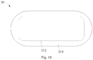
- the package body 31 includes a first package portion 313 and a second package portion 314 coupled to the first package portion 313.
- the first package portion 313 includes the second bottom surface 311, and the second package portion 314 includes the lateral surface 312.
- the recessed portion 33 can be defined by the first package portion 313 and the second package portion 314.
- the package body 31 can be provided with the recessed portion 33 by cutting off materials from the package body 31, i.e. via the cutting process, or the recessed portion 33 can also be directly formed together with the package body 31 by casting.
- a cross-section area of the first package portion 313 is smaller than a cross-section area of the second package portion 314.
- the first package portion 313 is received in the hole 222, and the second package portion 314 is supported on the support rim 22.
- the fingerprint identification chip 32 is received in the first package portion 313.
- a circuit junction of the fingerprint identification chip 32 is easy to be exposed, so as to be coupled to the flexible fingerprint circuit board 40.
- a shape and a size of the first package portion 313 are matched with a shape and a size of the fingerprint identification chip 32.
- the shape of the fingerprint identification chip 32 is similar to or same with the shape of the first package portion 313.
- the fingerprint identification chip 32 is configured to have a cuboid shape and the first package portion 313 is configured to have a cuboid or a rounded cuboid shape.
- the size of the first package portion 313 is slightly larger than the size of the fingerprint identification chip 32, so as to achieve an effect of packaging the fingerprint identification chip 32.
- the fingerprint chip package structure 30 has the more compact structure.
- the first package portion 313 has the rounded cuboid shape.
- the package body 31 can be better fitted with the fingerprint identification chip 32. Furthermore, the shape of the first package portion 313 is matched with a shape of the hole 222, that is to say, the hole 222 also has the rounded cuboid shape.
- the second package portion 314 includes a top surface 3141 connected to the lateral surface 312.
- the fingerprint chip package structure 30 includes a cover plate 34 fixed on the top surface 3141 of the second package portion 314.
- the cover plate 34 can be fixed on the top surface 3141 of the second package portion 314 through adhesive.
- the finger When the user performs the fingerprint identification operation, the finger can press on the cover plate 34.
- the cover plate 34 can protect the package body 31 from being damaged, so as to improve the reliability of the fingerprint chip package structure 30.
- the cover plate 34 can be made of materials having high hardness, for example the sapphires materials mentioned above.
- a shape and a size of the cover plate 34 are matched with a shape and a size of the top surface 3141 of the second package portion 314.
- the top surface 3141 is configured to have a long circle shape
- the cover plate 34 is also configured to have a long circle shape.
- An area of the cover plate 34 is slightly larger than an area of the top surface 3141 of the second package portion 314.
- the cover plate 34 can cover the second package portion 314 entirely.
- a sealing member 60 is provided between the second package portion 314 and the support rim 22.
- the sealing member 60 is configured to seal a gap between the second package portion 314 and the support rim 22.
- the sealing member 60 is made of silica gel (as illustrated in Fig. 2 ).
- the sealing member 60 can prevent foreign matters (such as water and dust) from entering the terminal 1000 from a gap between the fingerprint chip package structure 30 and the decoration enclosure 20, thereby improving the waterproof and dustproof effects of the terminal 1000.
- the recessed portion 33 includes a first surface 331 and a second surface 332 connected to the first surface 331, and the first surface 331 is perpendicular to the second surface 332.
- the recessed portion 33 is easy to be formed, and the first surface 331 is easy to be connected to the support rim 22.
- the first surface 331 is perpendicular to the second surface 332, so that the package body 31 is configured to have a stepped shape.
- the sealing member 60 is between the first surface 331 and the support rim 22.
- a junction of the first surface 331 and the second surface 332 is configured to be a transition fillet.
- defects are not easy to occur at the junction of the first surface 331 and the second surface 332 and the recessed portion 33 is easy to be formed.
Applications Claiming Priority (3)
| Application Number | Priority Date | Filing Date | Title |
|---|---|---|---|
| CN201620891063.5U CN206178736U (zh) | 2016-08-16 | 2016-08-16 | 装饰圈及终端 |
| CN201610676760.3A CN106095197B (zh) | 2016-08-16 | 2016-08-16 | 装饰圈及终端 |
| EP17176607.4A EP3285462B1 (fr) | 2016-08-16 | 2017-06-19 | Ensemble d'entrée et terminal |
Related Parent Applications (2)
| Application Number | Title | Priority Date | Filing Date |
|---|---|---|---|
| EP17176607.4A Division EP3285462B1 (fr) | 2016-08-16 | 2017-06-19 | Ensemble d'entrée et terminal |
| EP17176607.4A Division-Into EP3285462B1 (fr) | 2016-08-16 | 2017-06-19 | Ensemble d'entrée et terminal |
Publications (2)
| Publication Number | Publication Date |
|---|---|
| EP3376742A1 true EP3376742A1 (fr) | 2018-09-19 |
| EP3376742B1 EP3376742B1 (fr) | 2020-04-29 |
Family
ID=59093405
Family Applications (2)
| Application Number | Title | Priority Date | Filing Date |
|---|---|---|---|
| EP18171597.0A Active EP3376742B1 (fr) | 2016-08-16 | 2017-06-19 | Enceinte de décoration, ensemble d'entrée et terminal |
| EP17176607.4A Active EP3285462B1 (fr) | 2016-08-16 | 2017-06-19 | Ensemble d'entrée et terminal |
Family Applications After (1)
| Application Number | Title | Priority Date | Filing Date |
|---|---|---|---|
| EP17176607.4A Active EP3285462B1 (fr) | 2016-08-16 | 2017-06-19 | Ensemble d'entrée et terminal |
Country Status (4)
| Country | Link |
|---|---|
| US (2) | US10551947B2 (fr) |
| EP (2) | EP3376742B1 (fr) |
| ES (1) | ES2689917T3 (fr) |
| WO (1) | WO2018032883A1 (fr) |
Families Citing this family (2)
| Publication number | Priority date | Publication date | Assignee | Title |
|---|---|---|---|---|
| CN107908305B (zh) | 2016-08-16 | 2021-08-20 | Oppo广东移动通信有限公司 | 输入组件的制造方法、输入组件及终端 |
| CN113746959A (zh) * | 2020-05-29 | 2021-12-03 | 青岛海信移动通信技术股份有限公司 | 一种电子设备 |
Citations (4)
| Publication number | Priority date | Publication date | Assignee | Title |
|---|---|---|---|---|
| US20110309482A1 (en) * | 2010-06-18 | 2011-12-22 | Authentec, Inc. | Finger sensor including encapsulating layer over sensing area and related methods |
| US20150071509A1 (en) * | 2013-09-10 | 2015-03-12 | Apple Inc. | Biometric Sensor Stack Structure |
| CN105046190A (zh) * | 2015-05-08 | 2015-11-11 | 苏州迈瑞微电子有限公司 | 指纹识别模组 |
| CN105825165A (zh) * | 2015-11-20 | 2016-08-03 | 维沃移动通信有限公司 | 一种指纹识别模组、终端设备及装配方法 |
Family Cites Families (14)
| Publication number | Priority date | Publication date | Assignee | Title |
|---|---|---|---|---|
| US7524198B2 (en) * | 1999-08-04 | 2009-04-28 | Super Talent Electronics, Inc. | Press/push flash drive |
| US9030440B2 (en) * | 2012-05-18 | 2015-05-12 | Apple Inc. | Capacitive sensor packaging |
| CN103507561B (zh) | 2012-06-25 | 2016-02-24 | 张家港市九鼎机械有限公司 | 车轮传动机构及其加工装配方法以及采用该机构的自行车 |
| KR101368804B1 (ko) | 2013-06-26 | 2014-03-03 | (주)드림텍 | 데코 부품의 단차 구조가 적용된 지문인식 홈키 제조방법 및 그 지문인식 홈키 구조 |
| KR101639997B1 (ko) | 2015-04-28 | 2016-07-15 | 크루셜텍 (주) | 입력장치 |
| US9606654B2 (en) * | 2015-04-29 | 2017-03-28 | Yongqiang Li | Activated display |
| CN105117718A (zh) | 2015-09-25 | 2015-12-02 | 上海箩箕技术有限公司 | 指纹传感器装饰环组件及其使用方法 |
| CN205080566U (zh) | 2015-10-19 | 2016-03-09 | 深圳市欧菲投资控股有限公司 | 指纹识别装置及移动终端 |
| CN105303177B (zh) | 2015-10-21 | 2019-02-01 | Oppo广东移动通信有限公司 | 一种具有指纹识别功能的摄像头及相应的终端 |
| US10635878B2 (en) | 2015-10-23 | 2020-04-28 | Shenzhen GOODIX Technology Co., Ltd. | Optical fingerprint sensor with force sensing capability |
| CN105844237B (zh) | 2016-03-22 | 2018-05-04 | 广东欧珀移动通信有限公司 | 用于终端的指纹传感组件和具有其的终端 |
| CN105763681B (zh) | 2016-03-22 | 2019-02-05 | Oppo广东移动通信有限公司 | 用于通信终端的指纹传感组件和具有其的通信终端 |
| CN206178736U (zh) | 2016-08-16 | 2017-05-17 | 广东欧珀移动通信有限公司 | 装饰圈及终端 |
| CN108334226B (zh) | 2016-08-16 | 2021-03-26 | Oppo广东移动通信有限公司 | 装饰圈及终端 |
-
2017
- 2017-06-19 EP EP18171597.0A patent/EP3376742B1/fr active Active
- 2017-06-19 EP EP17176607.4A patent/EP3285462B1/fr active Active
- 2017-06-19 ES ES17176607.4T patent/ES2689917T3/es active Active
- 2017-06-20 US US15/627,697 patent/US10551947B2/en active Active
- 2017-06-27 WO PCT/CN2017/090339 patent/WO2018032883A1/fr active Application Filing
-
2018
- 2018-05-09 US US15/975,080 patent/US10175790B2/en active Active
Patent Citations (5)
| Publication number | Priority date | Publication date | Assignee | Title |
|---|---|---|---|---|
| US20110309482A1 (en) * | 2010-06-18 | 2011-12-22 | Authentec, Inc. | Finger sensor including encapsulating layer over sensing area and related methods |
| US20150071509A1 (en) * | 2013-09-10 | 2015-03-12 | Apple Inc. | Biometric Sensor Stack Structure |
| CN105046190A (zh) * | 2015-05-08 | 2015-11-11 | 苏州迈瑞微电子有限公司 | 指纹识别模组 |
| EP3296921A1 (fr) * | 2015-05-08 | 2018-03-21 | Microarray Microelectronics Corp., Ltd. | Module d'identification d'empreintes digitales |
| CN105825165A (zh) * | 2015-11-20 | 2016-08-03 | 维沃移动通信有限公司 | 一种指纹识别模组、终端设备及装配方法 |
Also Published As
| Publication number | Publication date |
|---|---|
| US10175790B2 (en) | 2019-01-08 |
| WO2018032883A1 (fr) | 2018-02-22 |
| EP3285462B1 (fr) | 2018-08-08 |
| US10551947B2 (en) | 2020-02-04 |
| EP3376742B1 (fr) | 2020-04-29 |
| ES2689917T3 (es) | 2018-11-16 |
| US20180052539A1 (en) | 2018-02-22 |
| EP3285462A1 (fr) | 2018-02-21 |
| US20180260046A1 (en) | 2018-09-13 |
Similar Documents
| Publication | Publication Date | Title |
|---|---|---|
| US10361862B2 (en) | Input assembly and terminal | |
| US10248251B2 (en) | Method for manufacturing input assembly, input assembly and terminal | |
| US10289892B2 (en) | Fingerprint chip package structure and terminal | |
| US10168806B2 (en) | Method for manufacturing input assembly, input assembly and terminal | |
| CN109145721B (zh) | 终端 | |
| CN106662900A (zh) | 具有指纹模组的屏幕组件及电子设备 | |
| US10175790B2 (en) | Decoration enclosure and terminal | |
| CN108156278A (zh) | 指纹芯片封装装置及终端 | |
| CN108334226A (zh) | 装饰圈及终端 | |
| US10433772B2 (en) | Fingerprint sensor and terminal using the same | |
| CN108448231B (zh) | 天线组件的制作方法、天线组件及电子设备 | |
| CN108511878B (zh) | 天线组件的制作方法、天线组件及电子设备 | |
| CN219227638U (zh) | 镜片组件、壳体部件和电子设备 | |
| CN116346970A (zh) | 电子设备 |
Legal Events
| Date | Code | Title | Description |
|---|---|---|---|
| PUAI | Public reference made under article 153(3) epc to a published international application that has entered the european phase |
Free format text: ORIGINAL CODE: 0009012 |
|
| STAA | Information on the status of an ep patent application or granted ep patent |
Free format text: STATUS: THE APPLICATION HAS BEEN PUBLISHED |
|
| AC | Divisional application: reference to earlier application |
Ref document number: 3285462 Country of ref document: EP Kind code of ref document: P |
|
| AK | Designated contracting states |
Kind code of ref document: A1 Designated state(s): AL AT BE BG CH CY CZ DE DK EE ES FI FR GB GR HR HU IE IS IT LI LT LU LV MC MK MT NL NO PL PT RO RS SE SI SK SM TR |
|
| STAA | Information on the status of an ep patent application or granted ep patent |
Free format text: STATUS: REQUEST FOR EXAMINATION WAS MADE |
|
| 17P | Request for examination filed |
Effective date: 20181120 |
|
| RBV | Designated contracting states (corrected) |
Designated state(s): AL AT BE BG CH CY CZ DE DK EE ES FI FR GB GR HR HU IE IS IT LI LT LU LV MC MK MT NL NO PL PT RO RS SE SI SK SM TR |
|
| STAA | Information on the status of an ep patent application or granted ep patent |
Free format text: STATUS: EXAMINATION IS IN PROGRESS |
|
| 17Q | First examination report despatched |
Effective date: 20190311 |
|
| RAP1 | Party data changed (applicant data changed or rights of an application transferred) |
Owner name: GUANGDONG OPPO MOBILE TELECOMMUNICATIONS CORP., LT |
|
| GRAP | Despatch of communication of intention to grant a patent |
Free format text: ORIGINAL CODE: EPIDOSNIGR1 |
|
| STAA | Information on the status of an ep patent application or granted ep patent |
Free format text: STATUS: GRANT OF PATENT IS INTENDED |
|
| INTG | Intention to grant announced |
Effective date: 20200120 |
|
| GRAS | Grant fee paid |
Free format text: ORIGINAL CODE: EPIDOSNIGR3 |
|
| GRAA | (expected) grant |
Free format text: ORIGINAL CODE: 0009210 |
|
| STAA | Information on the status of an ep patent application or granted ep patent |
Free format text: STATUS: THE PATENT HAS BEEN GRANTED |
|
| AC | Divisional application: reference to earlier application |
Ref document number: 3285462 Country of ref document: EP Kind code of ref document: P |
|
| AK | Designated contracting states |
Kind code of ref document: B1 Designated state(s): AL AT BE BG CH CY CZ DE DK EE ES FI FR GB GR HR HU IE IS IT LI LT LU LV MC MK MT NL NO PL PT RO RS SE SI SK SM TR |
|
| REG | Reference to a national code |
Ref country code: GB Ref legal event code: FG4D |
|
| REG | Reference to a national code |
Ref country code: CH Ref legal event code: EP |
|
| REG | Reference to a national code |
Ref country code: DE Ref legal event code: R096 Ref document number: 602017015897 Country of ref document: DE |
|
| REG | Reference to a national code |
Ref country code: AT Ref legal event code: REF Ref document number: 1265044 Country of ref document: AT Kind code of ref document: T Effective date: 20200515 |
|
| REG | Reference to a national code |
Ref country code: IE Ref legal event code: FG4D |
|
| REG | Reference to a national code |
Ref country code: NL Ref legal event code: MP Effective date: 20200429 |
|
| REG | Reference to a national code |
Ref country code: LT Ref legal event code: MG4D |
|
| PG25 | Lapsed in a contracting state [announced via postgrant information from national office to epo] |
Ref country code: IS Free format text: LAPSE BECAUSE OF FAILURE TO SUBMIT A TRANSLATION OF THE DESCRIPTION OR TO PAY THE FEE WITHIN THE PRESCRIBED TIME-LIMIT Effective date: 20200829 Ref country code: PT Free format text: LAPSE BECAUSE OF FAILURE TO SUBMIT A TRANSLATION OF THE DESCRIPTION OR TO PAY THE FEE WITHIN THE PRESCRIBED TIME-LIMIT Effective date: 20200831 Ref country code: FI Free format text: LAPSE BECAUSE OF FAILURE TO SUBMIT A TRANSLATION OF THE DESCRIPTION OR TO PAY THE FEE WITHIN THE PRESCRIBED TIME-LIMIT Effective date: 20200429 Ref country code: GR Free format text: LAPSE BECAUSE OF FAILURE TO SUBMIT A TRANSLATION OF THE DESCRIPTION OR TO PAY THE FEE WITHIN THE PRESCRIBED TIME-LIMIT Effective date: 20200730 Ref country code: LT Free format text: LAPSE BECAUSE OF FAILURE TO SUBMIT A TRANSLATION OF THE DESCRIPTION OR TO PAY THE FEE WITHIN THE PRESCRIBED TIME-LIMIT Effective date: 20200429 Ref country code: SE Free format text: LAPSE BECAUSE OF FAILURE TO SUBMIT A TRANSLATION OF THE DESCRIPTION OR TO PAY THE FEE WITHIN THE PRESCRIBED TIME-LIMIT Effective date: 20200429 Ref country code: NO Free format text: LAPSE BECAUSE OF FAILURE TO SUBMIT A TRANSLATION OF THE DESCRIPTION OR TO PAY THE FEE WITHIN THE PRESCRIBED TIME-LIMIT Effective date: 20200729 |
|
| REG | Reference to a national code |
Ref country code: AT Ref legal event code: MK05 Ref document number: 1265044 Country of ref document: AT Kind code of ref document: T Effective date: 20200429 |
|
| PG25 | Lapsed in a contracting state [announced via postgrant information from national office to epo] |
Ref country code: BG Free format text: LAPSE BECAUSE OF FAILURE TO SUBMIT A TRANSLATION OF THE DESCRIPTION OR TO PAY THE FEE WITHIN THE PRESCRIBED TIME-LIMIT Effective date: 20200729 Ref country code: LV Free format text: LAPSE BECAUSE OF FAILURE TO SUBMIT A TRANSLATION OF THE DESCRIPTION OR TO PAY THE FEE WITHIN THE PRESCRIBED TIME-LIMIT Effective date: 20200429 Ref country code: RS Free format text: LAPSE BECAUSE OF FAILURE TO SUBMIT A TRANSLATION OF THE DESCRIPTION OR TO PAY THE FEE WITHIN THE PRESCRIBED TIME-LIMIT Effective date: 20200429 Ref country code: HR Free format text: LAPSE BECAUSE OF FAILURE TO SUBMIT A TRANSLATION OF THE DESCRIPTION OR TO PAY THE FEE WITHIN THE PRESCRIBED TIME-LIMIT Effective date: 20200429 |
|
| PG25 | Lapsed in a contracting state [announced via postgrant information from national office to epo] |
Ref country code: AL Free format text: LAPSE BECAUSE OF FAILURE TO SUBMIT A TRANSLATION OF THE DESCRIPTION OR TO PAY THE FEE WITHIN THE PRESCRIBED TIME-LIMIT Effective date: 20200429 Ref country code: NL Free format text: LAPSE BECAUSE OF FAILURE TO SUBMIT A TRANSLATION OF THE DESCRIPTION OR TO PAY THE FEE WITHIN THE PRESCRIBED TIME-LIMIT Effective date: 20200429 |
|
| PG25 | Lapsed in a contracting state [announced via postgrant information from national office to epo] |
Ref country code: DK Free format text: LAPSE BECAUSE OF FAILURE TO SUBMIT A TRANSLATION OF THE DESCRIPTION OR TO PAY THE FEE WITHIN THE PRESCRIBED TIME-LIMIT Effective date: 20200429 Ref country code: IT Free format text: LAPSE BECAUSE OF FAILURE TO SUBMIT A TRANSLATION OF THE DESCRIPTION OR TO PAY THE FEE WITHIN THE PRESCRIBED TIME-LIMIT Effective date: 20200429 Ref country code: EE Free format text: LAPSE BECAUSE OF FAILURE TO SUBMIT A TRANSLATION OF THE DESCRIPTION OR TO PAY THE FEE WITHIN THE PRESCRIBED TIME-LIMIT Effective date: 20200429 Ref country code: SM Free format text: LAPSE BECAUSE OF FAILURE TO SUBMIT A TRANSLATION OF THE DESCRIPTION OR TO PAY THE FEE WITHIN THE PRESCRIBED TIME-LIMIT Effective date: 20200429 Ref country code: AT Free format text: LAPSE BECAUSE OF FAILURE TO SUBMIT A TRANSLATION OF THE DESCRIPTION OR TO PAY THE FEE WITHIN THE PRESCRIBED TIME-LIMIT Effective date: 20200429 Ref country code: CZ Free format text: LAPSE BECAUSE OF FAILURE TO SUBMIT A TRANSLATION OF THE DESCRIPTION OR TO PAY THE FEE WITHIN THE PRESCRIBED TIME-LIMIT Effective date: 20200429 Ref country code: RO Free format text: LAPSE BECAUSE OF FAILURE TO SUBMIT A TRANSLATION OF THE DESCRIPTION OR TO PAY THE FEE WITHIN THE PRESCRIBED TIME-LIMIT Effective date: 20200429 Ref country code: MC Free format text: LAPSE BECAUSE OF FAILURE TO SUBMIT A TRANSLATION OF THE DESCRIPTION OR TO PAY THE FEE WITHIN THE PRESCRIBED TIME-LIMIT Effective date: 20200429 Ref country code: ES Free format text: LAPSE BECAUSE OF FAILURE TO SUBMIT A TRANSLATION OF THE DESCRIPTION OR TO PAY THE FEE WITHIN THE PRESCRIBED TIME-LIMIT Effective date: 20200429 |
|
| REG | Reference to a national code |
Ref country code: CH Ref legal event code: PL |
|
| REG | Reference to a national code |
Ref country code: DE Ref legal event code: R097 Ref document number: 602017015897 Country of ref document: DE |
|
| PG25 | Lapsed in a contracting state [announced via postgrant information from national office to epo] |
Ref country code: PL Free format text: LAPSE BECAUSE OF FAILURE TO SUBMIT A TRANSLATION OF THE DESCRIPTION OR TO PAY THE FEE WITHIN THE PRESCRIBED TIME-LIMIT Effective date: 20200429 Ref country code: SK Free format text: LAPSE BECAUSE OF FAILURE TO SUBMIT A TRANSLATION OF THE DESCRIPTION OR TO PAY THE FEE WITHIN THE PRESCRIBED TIME-LIMIT Effective date: 20200429 |
|
| PLBE | No opposition filed within time limit |
Free format text: ORIGINAL CODE: 0009261 |
|
| STAA | Information on the status of an ep patent application or granted ep patent |
Free format text: STATUS: NO OPPOSITION FILED WITHIN TIME LIMIT |
|
| PG25 | Lapsed in a contracting state [announced via postgrant information from national office to epo] |
Ref country code: LU Free format text: LAPSE BECAUSE OF NON-PAYMENT OF DUE FEES Effective date: 20200619 |
|
| 26N | No opposition filed |
Effective date: 20210201 |
|
| REG | Reference to a national code |
Ref country code: BE Ref legal event code: MM Effective date: 20200630 |
|
| PG25 | Lapsed in a contracting state [announced via postgrant information from national office to epo] |
Ref country code: IE Free format text: LAPSE BECAUSE OF NON-PAYMENT OF DUE FEES Effective date: 20200619 Ref country code: LI Free format text: LAPSE BECAUSE OF NON-PAYMENT OF DUE FEES Effective date: 20200630 Ref country code: CH Free format text: LAPSE BECAUSE OF NON-PAYMENT OF DUE FEES Effective date: 20200630 |
|
| PG25 | Lapsed in a contracting state [announced via postgrant information from national office to epo] |
Ref country code: SI Free format text: LAPSE BECAUSE OF FAILURE TO SUBMIT A TRANSLATION OF THE DESCRIPTION OR TO PAY THE FEE WITHIN THE PRESCRIBED TIME-LIMIT Effective date: 20200429 Ref country code: BE Free format text: LAPSE BECAUSE OF NON-PAYMENT OF DUE FEES Effective date: 20200630 |
|
| PG25 | Lapsed in a contracting state [announced via postgrant information from national office to epo] |
Ref country code: TR Free format text: LAPSE BECAUSE OF FAILURE TO SUBMIT A TRANSLATION OF THE DESCRIPTION OR TO PAY THE FEE WITHIN THE PRESCRIBED TIME-LIMIT Effective date: 20200429 Ref country code: MT Free format text: LAPSE BECAUSE OF FAILURE TO SUBMIT A TRANSLATION OF THE DESCRIPTION OR TO PAY THE FEE WITHIN THE PRESCRIBED TIME-LIMIT Effective date: 20200429 Ref country code: CY Free format text: LAPSE BECAUSE OF FAILURE TO SUBMIT A TRANSLATION OF THE DESCRIPTION OR TO PAY THE FEE WITHIN THE PRESCRIBED TIME-LIMIT Effective date: 20200429 |
|
| PG25 | Lapsed in a contracting state [announced via postgrant information from national office to epo] |
Ref country code: MK Free format text: LAPSE BECAUSE OF FAILURE TO SUBMIT A TRANSLATION OF THE DESCRIPTION OR TO PAY THE FEE WITHIN THE PRESCRIBED TIME-LIMIT Effective date: 20200429 |
|
| P01 | Opt-out of the competence of the unified patent court (upc) registered |
Effective date: 20230412 |
|
| PGFP | Annual fee paid to national office [announced via postgrant information from national office to epo] |
Ref country code: FR Payment date: 20230626 Year of fee payment: 7 Ref country code: DE Payment date: 20230628 Year of fee payment: 7 |
|
| PGFP | Annual fee paid to national office [announced via postgrant information from national office to epo] |
Ref country code: GB Payment date: 20230626 Year of fee payment: 7 |