EP3376600A1 - Terminal blocks - Google Patents
Terminal blocks Download PDFInfo
- Publication number
- EP3376600A1 EP3376600A1 EP18161792.9A EP18161792A EP3376600A1 EP 3376600 A1 EP3376600 A1 EP 3376600A1 EP 18161792 A EP18161792 A EP 18161792A EP 3376600 A1 EP3376600 A1 EP 3376600A1
- Authority
- EP
- European Patent Office
- Prior art keywords
- spring element
- current bar
- end portion
- terminal
- conductive spring
- Prior art date
- Legal status (The legal status is an assumption and is not a legal conclusion. Google has not performed a legal analysis and makes no representation as to the accuracy of the status listed.)
- Granted
Links
Images


Classifications
-
- H—ELECTRICITY
- H01—ELECTRIC ELEMENTS
- H01R—ELECTRICALLY-CONDUCTIVE CONNECTIONS; STRUCTURAL ASSOCIATIONS OF A PLURALITY OF MUTUALLY-INSULATED ELECTRICAL CONNECTING ELEMENTS; COUPLING DEVICES; CURRENT COLLECTORS
- H01R9/00—Structural associations of a plurality of mutually-insulated electrical connecting elements, e.g. terminal strips or terminal blocks; Terminals or binding posts mounted upon a base or in a case; Bases therefor
- H01R9/22—Bases, e.g. strip, block, panel
- H01R9/24—Terminal blocks
- H01R9/26—Clip-on terminal blocks for side-by-side rail- or strip-mounting
- H01R9/2625—Clip-on terminal blocks for side-by-side rail- or strip-mounting with built-in electrical component
- H01R9/2641—Clip-on terminal blocks for side-by-side rail- or strip-mounting with built-in electrical component with built-in overvoltage protection
-
- H—ELECTRICITY
- H01—ELECTRIC ELEMENTS
- H01C—RESISTORS
- H01C7/00—Non-adjustable resistors formed as one or more layers or coatings; Non-adjustable resistors made from powdered conducting material or powdered semi-conducting material with or without insulating material
- H01C7/10—Non-adjustable resistors formed as one or more layers or coatings; Non-adjustable resistors made from powdered conducting material or powdered semi-conducting material with or without insulating material voltage responsive, i.e. varistors
- H01C7/12—Overvoltage protection resistors
- H01C7/126—Means for protecting against excessive pressure or for disconnecting in case of failure
-
- H—ELECTRICITY
- H01—ELECTRIC ELEMENTS
- H01H—ELECTRIC SWITCHES; RELAYS; SELECTORS; EMERGENCY PROTECTIVE DEVICES
- H01H37/00—Thermally-actuated switches
- H01H37/02—Details
- H01H37/08—Indicators; Distinguishing marks
-
- H—ELECTRICITY
- H01—ELECTRIC ELEMENTS
- H01H—ELECTRIC SWITCHES; RELAYS; SELECTORS; EMERGENCY PROTECTIVE DEVICES
- H01H37/00—Thermally-actuated switches
- H01H37/74—Switches in which only the opening movement or only the closing movement of a contact is effected by heating or cooling
- H01H37/76—Contact member actuated by melting of fusible material, actuated due to burning of combustible material or due to explosion of explosive material
- H01H37/761—Contact member actuated by melting of fusible material, actuated due to burning of combustible material or due to explosion of explosive material with a fusible element forming part of the switched circuit
-
- H—ELECTRICITY
- H01—ELECTRIC ELEMENTS
- H01T—SPARK GAPS; OVERVOLTAGE ARRESTERS USING SPARK GAPS; SPARKING PLUGS; CORONA DEVICES; GENERATING IONS TO BE INTRODUCED INTO NON-ENCLOSED GASES
- H01T1/00—Details of spark gaps
- H01T1/14—Means structurally associated with spark gap for protecting it against overload or for disconnecting it in case of failure
-
- H—ELECTRICITY
- H01—ELECTRIC ELEMENTS
- H01C—RESISTORS
- H01C7/00—Non-adjustable resistors formed as one or more layers or coatings; Non-adjustable resistors made from powdered conducting material or powdered semi-conducting material with or without insulating material
- H01C7/10—Non-adjustable resistors formed as one or more layers or coatings; Non-adjustable resistors made from powdered conducting material or powdered semi-conducting material with or without insulating material voltage responsive, i.e. varistors
- H01C7/12—Overvoltage protection resistors
-
- H—ELECTRICITY
- H01—ELECTRIC ELEMENTS
- H01H—ELECTRIC SWITCHES; RELAYS; SELECTORS; EMERGENCY PROTECTIVE DEVICES
- H01H37/00—Thermally-actuated switches
- H01H37/74—Switches in which only the opening movement or only the closing movement of a contact is effected by heating or cooling
- H01H37/76—Contact member actuated by melting of fusible material, actuated due to burning of combustible material or due to explosion of explosive material
- H01H37/761—Contact member actuated by melting of fusible material, actuated due to burning of combustible material or due to explosion of explosive material with a fusible element forming part of the switched circuit
- H01H2037/762—Contact member actuated by melting of fusible material, actuated due to burning of combustible material or due to explosion of explosive material with a fusible element forming part of the switched circuit using a spring for opening the circuit when the fusible element melts
- H01H2037/763—Contact member actuated by melting of fusible material, actuated due to burning of combustible material or due to explosion of explosive material with a fusible element forming part of the switched circuit using a spring for opening the circuit when the fusible element melts the spring being a blade spring
-
- H—ELECTRICITY
- H01—ELECTRIC ELEMENTS
- H01T—SPARK GAPS; OVERVOLTAGE ARRESTERS USING SPARK GAPS; SPARKING PLUGS; CORONA DEVICES; GENERATING IONS TO BE INTRODUCED INTO NON-ENCLOSED GASES
- H01T4/00—Overvoltage arresters using spark gaps
- H01T4/04—Housings
Definitions
- the invention relates to a terminal block with a housing, with at least one connection element, with at least one current bar, with a protective element and with an electrically conductive spring element, wherein the first terminal of the protective element is electrically conductively connected to the at least one connection element.
- the first end portion of the conductive spring element is electrically conductively connected to the at least one current bar, while the second end portion of the spring element in the normal state of the protective element is electrically conductively connected via a thermally disconnecting connection with the second terminal of the protective element.
- the protective element is then separated electrically.
- Terminal blocks have been known for decades and are used millions of times in the wiring of electrical systems and devices.
- the terminals are often snapped onto mounting rails, which in turn can be arranged in a plurality in a control cabinet.
- the terminal blocks can also be fastened alone or as a plurality of terminal blocks in a wall opening of a housing wall, in particular in an opening in a control cabinet wall.
- Electrical terminal blocks are often connection terminals, so that they have at least two connection elements which are connected to one another in an electrically conductive manner, as a rule via a current bar arranged in the terminal housing.
- terminal elements predominantly screw terminals
- spring-cage terminals or leg spring terminals are used in terminal blocks.
- this basic type of terminal blocks which is often referred to as a feed-through terminal
- there are a variety of different types of terminal block which are specially adapted to the particular application.
- protective conductor terminals, disconnect terminals and installation terminals may be mentioned.
- terminal blocks in which additional electrical or electronic components are arranged in the housing in addition to the connection elements and the at least one current bar.
- the protective elements may in particular be overvoltage-limiting components, for example varistors, diodes or gas-filled surge arresters with which the connected line and signal paths are protected against overvoltages.
- Such terminal blocks then have the function of overvoltage protection devices and are used extensively, in particular in measurement, control and regulation technology.
- an overvoltage protection element which has a thermal separation device for monitoring the state of a varistor.
- the first terminal is connected via a flexible conductor to a rigid separating element whose end remote from the flexible conductor is connected via a soldering point to a connection lug provided on the varistor.
- the other connection is permanently connected to a second connection lug on the varistor via a flexible conductor.
- the conductive connecting element is acted upon by a spring system with a force that causes the connecting element is linearly moved away during the separation of the solder joint from the terminal lug, so that the varistor is electrically disconnected under thermal overload.
- the DE 695 03 743 T2 discloses an overvoltage protection element with two varistors, which has two conductive connecting elements, by means of which the varistors can each be separated individually at the end of their life.
- the connecting elements are each designed as resilient separating tongues, the first end of the separating tongue being integrally connected or soldered to the first connecting contact and the second end of the separating tongue being fastened in the normal state of the overvoltage protection element via a soldering point to a connection tongue on the varistor. If there is an inadmissible heating of the varistor, this leads to a melting of the solder joint. Since the separation tongue is deflected in the soldered state from its rest position and thus biased, the free end of the separation tongue springs upon softening of the solder joint away from the terminal tab of the varistor, whereby the varistor is electrically disconnected.
- terminal blocks which have a corresponding protective element
- a resilient separating tongue for monitoring the protective element which is connected at one end via a solder joint as thermally disconnecting connection with a terminal of the protective element.
- the other end of the separation tongue is firmly soldered either with a connection of a printed circuit board or with a current bar, which means an increased production cost.
- the problem is also that such terminal blocks increasingly smaller and smaller dimensions, especially smaller widths should have, which further complicates the assembly.
- the present invention is therefore an object of the invention to provide a terminal described above, which can be produced with the least possible effort and thus at low cost.
- the assembly of the terminal block should be as simple as possible and preferably carried out largely automated.
- the connection between the conductive spring element and the current bar is thus not by a relatively expensive soldering, but by a positive connection between the current bar and the conductive spring element, so that the spring element can be attached by a purely mechanical assembly step to the current bar ,
- the spring element is fixed to the current bar via the at least one Z-shaped tongue.
- the extending in the longitudinal direction of the current bar tongue protrudes through the recess in the current bar, wherein the spring element is clamped by the tongue to the current bar.
- the current bar has an increase, for example, produced by embossing, to which a corresponding recess is formed in the first end portion of the spring element, in which engages the increase in the assembled state of current bar and spring element.
- the increase and the recess which are preferably each rectangular or square, a defined position and position of the spring element relative to the current bar can be ensured in a simple manner, both in the direction of the longitudinal extent of the current bar and transversely to the longitudinal extent.
- the spring element Since most of the spring element is made of a harder material than the current bar, it is usually easier to form the increase in the current bar and the recess on the spring element, the latter for example by punching. Alternatively, however, it is also possible in principle that the first end portion of the conductive spring element has an increase and in the current bar a corresponding recess is formed, in which engages the increase in the mounted state of current bar and spring element. Also in this case, a secure and unambiguous positioning of the spring element is ensured relative to the current bar by the interaction of increase and recess.
- the recess in the current bar to an edge of the current bar and the recess in the first end portion of the spring element to the opposite edge of the spring element open.
- the recess in the spring element is thereby pushed from the side over the increase in the current bar and the tongue inserted into the laterally open recess in the current bar.
- only a single-axis mounting movement is perpendicular to the longitudinal extent of the current bar and thus usually also perpendicular to the level of the terminal block required, which allows easy automation of assembly.
- a bevel at the transition from the longitudinal side to the bottom is realized according to a further advantageous embodiment between the Z-shaped tongue of the first end portion of the conductive spring element and the current bar.
- the distance between the top of the tongue and the underside of the spring element is thus slightly less than the thickness of the current bar. Also by this interference fit thus a secure and stable attachment of the spring element is ensured at the current bar.
- one recess is formed on the current bar, to which the first end portion of the spring element correspondingly has only one Z-shaped tongue.
- two opposing recesses are formed in the current bar, to which the first end portion of the conductive spring element has two mutually parallel Z-shaped tongues.
- the two tongues each extend from the top of the current bar through a recess to the underside of the current bar, so that the free ends of the tongues bear against the underside of the current bar.
- both the first end portion of the spring element and the current bar are then formed mirror-symmetrically to their respective longitudinal axis at least in the region in which the two components are connected to each other.
- the current bar preferably has an elevation, to which a corresponding recess is formed in the end portion of the spring element, in which engages the increase in the mounted state of spring element and current bar.
- the increase and the Recess each formed or arranged symmetrically to the center plane of the current bar and the first end portion of the spring element.
- the top of the current bar and / or the bottom of the first end portion of the conductive spring element point or line-shaped elevations, such as grooves, beads or embossing.
- a reduced contact surface is formed between the spring element and the current bar.
- the spring element not only serves to separate the protective element in the event of a spring, but also flows over the spring element and the current bar and the derived during the response of the protective element shock or overcurrent.
- a good electrical connection with the lowest possible contact resistance between the first end portion of the spring element and the current bar is advantageous.
- At least one recess is formed in the current bar and that the first end section of the conductive spring element has at least one Z-shaped tongue.
- the arrangement of recess and tongue can also be reversed, so that in the first end portion of the conductive spring element at least one recess is formed and the current bar has a Z-shaped tongue. This extends in the mounted state through the recess on the upper side of the spring element, so that the free end of the tongue rests on the upper side of the spring element.
- the Z-shaped tongue is thus formed on the current bar, for which purpose it is correspondingly punched free from the current bar and bent.
- the tongue also extends in the longitudinal direction of the current bar and, based on the width of the current bar, is arranged centrally.
- the recess in the first end portion of the spring element can be easily manufactured by punching.
- the assembly of current bar and spring element can be particularly simple, that the recess in the spring element to one edge of the Spring element is open, so that the spring element can be pushed during assembly perpendicular to the longitudinal extent of the current bar on this.
- the Z-shaped tongue extends through the recess, wherein in the mounted state, the free end of the tongue rests on the upper side of the spring element.
- a press fit is realized between the Z-shaped tongue of the current bar and the first end portion of the spring element, so that the spring element is securely clamped by the tongue on the current bar.
- a chamfer is preferably formed on the tongue at the transition from the longitudinal side to the bottom.
- the current bar additionally has an increase, to which a corresponding recess is formed in the first end portion of the conductive spring element, in which engages the increase in the mounted state.
- a single-axis mounting movement is possible, the recess in the spring element at the edge, which faces the current bar in the mounting direction, open, so that the spring element can be pushed during assembly perpendicular to the longitudinal extent of the current bar on the current bar.
- a stop may be formed on the upper side of the current bar, against which the first end section of the conductive spring element rests with its end face. In this embodiment can then be dispensed with the formation of a recess in the first end portion of the spring element.
- the electrically conductive spring element is preferably designed as a sheet bending spring, ie as a leaf spring, which is claimed primarily on bending.
- the spring element is shaped so that the first end portion of the spring element in the mounted state parallel to the current bar runs.
- an angled central portion or a C-shaped central portion is arranged between the first end portion and the second end portion.
- the central portion of the spring element is not straight but C-shaped or angled, the possibility is created, even with a small available space to use a spring element, which has a sufficient length, so that for a safe triggering required spring force of the spring element can be ensured without the yield strength of the spring element is exceeded.
- the electrically conductive spring element according to the first embodiment variant has an angled middle section, then it preferably has two limbs which are arranged at an angle ⁇ to one another.
- the angle ⁇ is formed as an acute angle, preferably less than 75 °, in particular less than 65 °.
- the angle ⁇ between the two legs of the angled central portion may be for example between 50 ° and 60 °.
- the first end section and the second end section of the spring element are also each arranged at an angle to the adjacent leg of the middle section of the spring element.
- the angle ⁇ between the first end portion and the first leg of the central portion of the spring element is formed as an obtuse angle, preferably greater than 110 °, in particular greater than 125 °.
- the distance a from the transition from the first end portion to the central portion of the conductive spring element to the Z-shaped tongue as large as possible, so that a lever arm between the support point of the spring element on the current bar and the area where the spring element is set at the current bar exists.
- the distance a is at least as large as the widths of the current bar. This prevents that there is a bending of the current bar or the spring element due to the bending force arising from the spring force at the weakened by the recess attachment point in the current bar.
- a display element is slidably disposed in the housing of the terminal, which cooperates with the second end portion of the conductive spring element, that the display element is in a display position when the second Endab mustard of the conductive spring element with separated thermal connection from the second terminal of the protective element is spaced. If there is a separation of the thermal connection between the second end portion of the spring element and the second terminal of the protective element due to inadmissible heating of the protective element, this leads to the fact that the second end portion of the spring element springs away from the second terminal of the protective element.
- the movement of the second end portion of the spring element leads to a corresponding movement of the display element, which can be used in a simple manner for displaying the triggered state of the protective element.
- a window is formed through which a display surface of the display element is visible when the display element has been moved by spring-back of the spring element in its display position.
- the display element is spent by a purely linear movement from the first position to the display position.
- the spring element is designed so that it is still somewhat deflected out of its rest position when the display element is in the display position. As a result, the display element is also securely held in the display position with a certain spring force.
- Fig. 1 shows an embodiment of a terminal block 1 according to the invention from the side.
- the terminal block 1 has a housing 2 made of plastic, in which two connection elements 3, 4 are arranged on two levels are, wherein the connection elements 3, 4 a plane in each case via a current bar 5, 6 are interconnected.
- a protective element 7, which is a varistor in the present case, and an electrically conductive spring element 8 are arranged in the housing 2 of the terminal block 1.
- the first terminal 7 a of the protective element 7 is connected via the upper current bar 6 with the two upper terminal elements 3.
- the electrical connection of the first terminal 7a of the protective element 7 with the connection elements 3 does not necessarily have to take place via a current bar.
- the current bar 6 it is also possible to use a flexible conductor or the printed conductor of a printed circuit board for the electrical connection of the first terminal 7a of the protective element 7 to at least one of the two connecting elements 3.
- the electrically conductive spring element 8 serves for the electrical connection of the second terminal 7b of the protective element 7.
- the first end section 9 of the spring element 8 is initially electrically conductively connected to the lower current bar 5.
- the second end section 10 of the spring element 8 is electrically connected to the second terminal 7 b of the protective element 7 via a thermally disconnecting connection 11.
- the thermally splitting connection 11, which is a corresponding solder is designed such that the solder melts and thus separates the connection 11 when the protective element 7 has exceeded a predetermined limit temperature. This then causes the deflected from its rest position spring element 8 springs back, with the second end portion 10 of the spring element 8 away from the second terminal 7b of the protective element 7, so that the protective element 7 is electrically disconnected.
- the housing 2 still has a mounting foot 12, with which the terminal block 1 can be mounted on a support rail 13.
- a metallic connection element 14 is arranged in the housing 2 of the terminal block 1, via which the lower current bar 5 is electrically connected in the latched state with the support rail 13. If the carrier rail 13 is at ground potential, an electrical connection of the second terminal 7b of the protective element 7 to ground potential can also be effected only via the spring element 8, the current bar 5 and the connection element 14, so that the lower connection elements 4 are not absolutely necessary.
- both current bars 5, 6 are connected at their ends in each case with a connecting element 3,4, as in Fig. 1 is shown. In this case, it may be in the connection elements 3, 4 for connecting electrical conductors as in the present case to screw terminals.
- other connection elements such as tension spring clamps or leg spring clamps can be used.
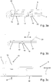
- Fig. 2 shows an embodiment of a fixed to a current bar 5 spring element 8, in perspective view.
- An enlarged view of the attachment or the connection region of current bar 5 and spring element 8 shows Fig. 3 , in perspective ( Fig. 3a ), of the page ( Fig. 3b ) and from above ( Fig. 3c ).
- Other variants of the connection of current bar 5 and spring element 8 show the Fig. 4 to 9 , All embodiments shown here is common that the connection between the conductive spring element 8 and the current bar 5 is not carried out by a complex soldering or welding connection but by a positive and non-positive connection, so that the spring element 8 by a purely mechanical assembly process to the current bar 5 can be attached.
- the current bar 5 In the first embodiment according to the Fig. 2 and 3 is formed in the current bar 5 a recess 15 through which a Z-shaped tongue 16 extends, which is punched free at the first end portion 9 of the spring element 8 and bent.
- the tongue 16 extends from the top of the current bar 5 through the recess 15 to the underside of the current bar 5, where the free end 17 of the tongue 16 is applied.
- the current bar 5 still has a rectangular elevation 18, to which in the first end portion 9 of the spring element 8, a corresponding recess 19 is formed, into which the elevation 18 engages.
- the spring element 8 is securely fixed in its position and orientation relative to the current bar 5, wherein a lifting of the first end portion 9 of the spring element 8 is prevented by the current bar 5 through the inserted into the recess 15 Z-shaped tongue 16.
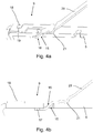
- Fig. 4 shows an enlarged view of a variant of the attachment of current bar 5 and spring element 8 according to Fig. 2 , in perspective ( Fig. 4a ) and from the side ( Fig. 4b ).
- the current bar 5 has a recess 15 through which the Z-shaped tongue 16 formed at the first end portion 9 of the spring element 8 extends.
- an elevation 18 is pronounced on the upper side of the current bar 5, which engages in a recess 19 in the first end portion 9 of the spring element 8.
- a survey 21 whereby between the current bar 5 and the spring element 8 is formed a reduced contact surface.
- the elevation 21 is realized by an introduced in the spring element 8 bead.
- a corresponding increase, for example, a perpendicular to the longitudinal extent L of the current bar 5 extending groove may also be provided on the upper side of the current bar 5.
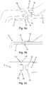
- FIG. 5 shows a second embodiment of a fixed to a current bar 5 spring element 8 in a perspective view.
- An enlarged view of the connection region of current bar 5 and spring element 8 is shown in FIG Fig. 6 shown, in a perspective view ( Fig. 6a ), of the page ( Fig. 6b ) and from above ( Fig. 6c ).
- a major difference between the in the Fig. 2 to 4 illustrated first embodiment and in the Fig. 5 and 6 illustrated second embodiment is that in the current bar 5 two opposing recesses 15, 15 'are formed and the first end portion 9 of the spring element 8 has two mutually parallel Z-shaped tongues 16, 16'.
- the two tongues 16, 16 'each extend from the upper side of the current bar 5 through a recess 15, 15' to the underside of the current bar, where the free ends 17 of the tongues 16, 16 'rest against the lower side of the current bar 5.
- the assembly of the spring element 8 on the current bar 5 is not effected by lateral insertion but by pivoting the first end portion 9 of the spring element 8, including the free ends 17, 17 'of the tongues 16, 16' first from above into the recesses 15, 15 'inserted and then the spring element 8 - in the arrangement according to Fig. 5 - is pivoted clockwise.
- the formed on the top of the current bar 5 elevation 18 engages in the formed in the first end portion 9 of the spring member 8 recess 19, whereby the spring element 8 is accurately determined in its position and position on the current bar 5.
- the current bar 5 and the first end portion 9 of the spring element 8 are formed in the connection region mirror-symmetrical to the center plane of the current bar 5 and the spring element 8.
- a rotation of the spring element 8 relative to the current bar 5 is reliably prevented.
- the assembly of the spring element 8 is more expensive, since the fasteners can not be produced by a simple linear assembly movement.
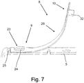
- Fig. 7 shows a third embodiment of the connection of a current bar 5 with a spring element 8, which initially differs from the previously described embodiments in that here in the first end portion 9 of the spring member 8, a recess 22 is formed and the current bar 5 has a Z-shaped tongue 23 ,
- the tongue 23 extends in such a way through the recess 22 that the free end 24 of the tongue 23 rests on the upper side of the spring element 8. Since the recess 22 in the first end portion 9 of the spring element 8 to a (rear) edge of the spring element 8 is open, also in this case the assembly can be done simply by pushing the side of the spring element 8 on the current bar 5. In this case, the central region of the Z-shaped tongue 23 slides into the recess 22, while at the same time the region of the first end portion 9 of the spring element 8 adjoining the recess 22 is pushed under the free end 24 of the tongue 23.
- a press fit between the Z-shaped tongue 23 and the first end portion 9 of the spring element 8 may be realized, whereby the spring element 8 is securely clamped to the current bar 5.
- a chamfer formed on the tongue 23 can facilitate the insertion of the end section 9 of the spring element 8.
- a stop 25 is additionally formed, which serves as an anti-rotation device for the spring element 8.
- the stop 25 can also facilitate an accurate and tolerance-free positioning of the spring element 8 on the current bar 5, when the first end portion 9 of the conductive spring element 8 rests with its end face 26 on the Anschag 25.
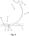
- Fig. 9 shows a further variant of the first embodiment of a fixed to a current bar 5 spring element 8.
- the spring element 8 is formed as a sheet bending spring, which consists of a corresponding spring material punched out and bent.
- the first end portion 9 which is parallel to the current bar 5 in the assembled state, and the second end portion 10, an angled central portion 27 is arranged.
- a C-shaped central portion 28 is formed in the embodiments according to the Fig. 7 to 9 between the first end portion 9 and the second end portion 10 of the spring element 8.
- a spring element 8 can be realized, which has a sufficient length even with limited space to provide the required spring force is available, so that the second end portion 10 of the spring element. 8 upon reaching the limit temperature of the protective element 7 reliably and reliably springs away from the second terminal 7 b of the protective element 7.
- the central portion 27 of the spring element 8 has two legs 29, 30, which are arranged at an angle ⁇ to each other, wherein the angle ⁇ in the illustrated embodiment is approximately 55 °.
- the angle ⁇ between the first end portion 9 and the first leg 29 of the central portion 27 is about 135 °.
- the deflection path by which the second end section 10 is deflected out of the rest position of the spring element 8 when it is connected to the second connection 7b of the protection element 7 via the thermally disconnecting connection 11 can be set in a simple manner , If the angle ⁇ is reduced with otherwise identical dimensions, then this leads to the fact that the spring element 8 is deflected further in the normal state of the protective element 7, so that a larger preload force acts on the thermally splitting connection 11.
- the first leg 29 of the central portion 27 does not directly adjoin the connecting portion of the first end portion 9 of the spring element 8. Rather, there is a distance a between the first leg 29 of the central portion 27 and the base of the Z-shaped tongue 16.
- the distance a is preferably at least as large as the width of the current bar 5.
- the first end portion 9 of the spring element 8 has the same width as the current bar 5, whereby the spring element 8 can be supported laterally on the housing 2 in this area.
- the second end portion 10 of the spring element 8, however, has a smaller width, so that the second end portion 10 is not hindered by the spring back 2 of the spring element 2 by lateral contact with the housing 2.
- a tab 32 is laterally bent at the second end portion 10 of the spring element 8, wherein the angle between the tab 32 and the second end portion 10 approximately 90th ° is.
- the formation of a bent tab 32 has the additional advantage that thereby a certain tolerance compensation with respect to the position of the second terminal 7b of the protective element 7 is possible.
- different protection elements 7 can be used with slightly different dimensions.
- a display element 33 is slidably disposed in the housing 2 of the terminal block 1, with the aid of which a user is displayed that the thermally disconnecting compound 11 has separated and thus the protective element 7 has been electrically disconnected.
- the free end of the second end portion 10 of the spring element 8 engages in a corresponding receptacle 34 on the display element 33, so that upon spring-back of the spring element 8, the display element 33 is displaced by the spring element 8 in its display position.
- display position is a preferably color-coded display surface 35 of the display element 33 below a formed in the housing 2 viewing window, so that the state of the protective element 7 - connected or disconnected - is easily recognizable to a user.
Abstract
Dargestellt und beschrieben ist eine Reihenklemme (1) mit einem Gehäuse (2), mit mindestens einem Anschlusselement (3, 4), mit mindestens einem Strombalken (5, 6), mit einem Schutzelement (7) und mit einem elektrisch leitfähigen Federelement (8), wobei der erste Anschluss (7a) des Schutzelements (7) mit dem mindestens einen Anschlusselement (3, 4) elektrisch leitend verbunden ist, wobei der erste Endabschnitt (9) des leitfähigen Federelements (8) mit dem mindestens einen Strombalken (5) elektrisch leitend verbunden ist, wobei der zweite Endabschnitt (10) des leitfähigen Federelements (8) im Normalzustand des Schutzelements (7) über eine thermisch auftrennende Verbindung (11) mit dem zweiten Anschluss (7b) des Schutzelements (7) elektrisch leitend verbunden ist, und wobei bei Überschreiten einer vorgegebenen Grenztemperatur des Schutzelements (7) die thermisch auftrennende Verbindung (11) zwischen dem zweiten Endabschnitt (10) des leitfähigen Federelements (8) und dem zweiten Anschluss (7b) des Schutzelements (7) auftrennt und sich der zweite Endabschnitt (10) des leitfähigen Federelements (8) aufgrund der Federkraft des Federelements (8) in eine Position bewegt, in der der zweite Endabschnitt (10) vom zweiten Anschluss (7b) des Schutzelements (7) beabstandet ist. Um den Aufbau und die Montage der Reihenklemme (1) weiter zu vereinfachen, ist vorgesehen, dass im Strombalken (5) mindestens eine Ausnehmung (15) ausgebildet ist und der erste Endabschnitt (9) des leitfähigen Federelements (8) mindestens eine Z-förmige Zunge (16) aufweist, die sich von der Oberseite des Strombalkens (5) durch die Ausnehmung (15) zur Unterseite des Strombalkens (5) erstreckt, so dass das freie Ende (17) der Zunge (16) an der Unterseite des Strombalkens (5) anliegt.Shown and described is a terminal block (1) with a housing (2), with at least one connection element (3, 4), with at least one current bar (5, 6), with a protective element (7) and with an electrically conductive spring element (8 ), wherein the first terminal (7a) of the protective element (7) is electrically conductively connected to the at least one terminal element (3, 4), the first end section (9) of the conductive spring element (8) being connected to the at least one current bar (5). is electrically conductively connected, wherein the second end portion (10) of the conductive spring element (8) in the normal state of the protective element (7) via a thermally disconnecting compound (11) to the second terminal (7b) of the protective element (7) is electrically connected, and wherein when a predetermined limit temperature of the protective element (7) is exceeded, the thermally isolating connection (11) between the second end portion (10) of the conductive spring element (8) and the second Ans 7b) of the protective element (7) separates and the second end portion (10) of the conductive spring element (8) moves due to the spring force of the spring element (8) in a position in which the second end portion (10) from the second terminal (7b ) of the protective element (7) is spaced. In order to further simplify the construction and assembly of the terminal block (1), it is provided that at least one recess (15) is formed in the current bar (5) and the first end section (9) of the conductive spring element (8) is at least one Z-shaped one Tongue (16) extending from the top of the current bar (5) through the recess (15) to the bottom of the current bar (5), so that the free end (17) of the tongue (16) at the bottom of the current bar ( 5) is applied.
Description
Die Erfindung betrifft eine Reihenklemme mit einem Gehäuse, mit mindestens einem Anschlusselement, mit mindestens einem Strombalken, mit einem Schutzelement und mit einem elektrisch leitfähigen Federelement, wobei der erste Anschluss des Schutzelements mit dem mindestens einen Anschlusselement elektrisch leitend verbunden ist. Der erste Endabschnitt des leitfähigen Federelements ist mit dem mindestens einen Strombalken elektrisch leitend verbunden, während der zweite Endabschnitt des Federelements im Normalzustand des Schutzelements über eine thermisch auftrennende Verbindung mit dem zweiten Anschluss des Schutzelements elektrisch leitend verbunden ist. Bei Überschreiten einer vorgegebenen Grenztemperatur des Schutzelements trennt die thermisch auftrennende Verbindung zwischen dem zweiten Endabschnitt des Federelements und dem zweiten Anschluss des Schutzelements auf, so dass sich der zweite Endabschnitt des Federelements aufgrund der Federkraft des Federelements in eine Position bewegt, in der er vom zweiten Anschluss des Schutzelements beabstandet ist. Das Schutzelement ist dann elektrisch abgetrennt.The invention relates to a terminal block with a housing, with at least one connection element, with at least one current bar, with a protective element and with an electrically conductive spring element, wherein the first terminal of the protective element is electrically conductively connected to the at least one connection element. The first end portion of the conductive spring element is electrically conductively connected to the at least one current bar, while the second end portion of the spring element in the normal state of the protective element is electrically conductively connected via a thermally disconnecting connection with the second terminal of the protective element. When a predetermined limit temperature of the protective element is exceeded, the thermally disconnecting connection between the second end portion of the spring element and the second terminal of the protective element, so that the second end portion of the spring element moves due to the spring force of the spring element in a position in which it from the second terminal the protective element is spaced. The protective element is then separated electrically.
Reihenklemmen sind seit Jahrzehnten bekannt und werden millionenfach bei der Verdrahtung elektrischer Anlagen und Geräte eingesetzt. Die Klemmen werden häufig auf Tragschienen aufgerastet, welche ihrerseits in einer Mehrzahl in einem Schaltschrank angeordnet sein können. Daneben können die Reihenklemmen aber auch alleine oder zu mehreren als Klemmenblock in einer Wandöffnung einer Gehäusewand, insbesondere in einer Öffnung in einer Schaltschrankwand, befestigt sein.Terminal blocks have been known for decades and are used millions of times in the wiring of electrical systems and devices. The terminals are often snapped onto mounting rails, which in turn can be arranged in a plurality in a control cabinet. In addition, however, the terminal blocks can also be fastened alone or as a plurality of terminal blocks in a wall opening of a housing wall, in particular in an opening in a control cabinet wall.
Elektrische Reihenklemmen sind häufig Verbindungsklemmen, so dass sie mindestens zwei Anschlusselemente aufweisen, die elektrisch leitend miteinander verbunden sind, in der Regel über einen im Klemmengehäuse angeordneten Strombalken. Als Anschlusselemente werden dabei in Reihenklemmen überwiegend Schraubklemmen, Zugfederklemmen oder Schenkelfederklemmen verwendet. Neben diesem Grundtyp der Reihenklemmen, der häufig auch als Durchgangsklemme bezeichnet wird, gibt es eine Vielzahl von unterschiedlichen Reihenklemmentypen, die speziell an die jeweiligen Anwendungsfälle angepasst sind. Als Beispiel seien Schutzleiterklemmen, Trennklemmen und Installationsklemmen genannt.Electrical terminal blocks are often connection terminals, so that they have at least two connection elements which are connected to one another in an electrically conductive manner, as a rule via a current bar arranged in the terminal housing. As terminal elements predominantly screw terminals, spring-cage terminals or leg spring terminals are used in terminal blocks. In addition to this basic type of terminal blocks, which is often referred to as a feed-through terminal, there are a variety of different types of terminal block, which are specially adapted to the particular application. As an example, protective conductor terminals, disconnect terminals and installation terminals may be mentioned.
Außerdem gibt es Reihenklemmen, bei denen neben den Anschlusselementen und dem mindestens einem Strombalken zusätzliche elektrische oder elektronische Bauelemente im Gehäuse angeordnet sind. Bei den Schutzelementen kann es sich insbesondere um überspannungsbegrenzende Bauelemente handeln, beispielsweise Varistoren, Dioden oder gasgefüllte Überspannungsableiter, mit denen die angeschlossenen Leitungs- und Signalpfade gegen Überspannungen geschützt werden. Derartige Reihenklemmen haben dann die Funktion von Überspannungsschutzgeräten und werden insbesondere in der Mess-, Steuerungs- und Regelungstechnik umfangreich eingesetzt.In addition, there are terminal blocks in which additional electrical or electronic components are arranged in the housing in addition to the connection elements and the at least one current bar. The protective elements may in particular be overvoltage-limiting components, for example varistors, diodes or gas-filled surge arresters with which the connected line and signal paths are protected against overvoltages. Such terminal blocks then have the function of overvoltage protection devices and are used extensively, in particular in measurement, control and regulation technology.
Zur Überwachung des Zustandes eines Schutzelements ist es bekannt, dieses über eine thermisch auftrennende Verbindung mit einem Anschlusselement zu verbinden. Durch die thermische Trennstelle wird gewährleistet, dass das Schutzelement bei einer unzulässigen Erwärmung elektrisch abgetrennt wird. Aus der
Die
Auch bei Reihenklemmen, die ein entsprechendes Schutzelement aufweisen, ist es bekannt, zur Überwachung des Schutzelements eine federnde Trennzunge einzusetzen, die mit ihrem einen Ende über eine Lötstelle als thermisch auftrennende Verbindung mit einem Anschluss des Schutzelements verbunden ist. Das andere Ende der Trennzunge ist dabei entweder mit einem Anschluss einer Leiterplatte oder mit einem Strombalken fest verlötet, was jeweils einen erhöhten Fertigungsaufwand bedeutet. Problematisch ist dabei auch, dass derartige Reihenklemmen zunehmend immer kleinere Abmessungen, insbesondere geringere Breiten, aufweisen sollen, was die Montage zusätzlich erschwert.Even with terminal blocks, which have a corresponding protective element, it is known to use a resilient separating tongue for monitoring the protective element, which is connected at one end via a solder joint as thermally disconnecting connection with a terminal of the protective element. The other end of the separation tongue is firmly soldered either with a connection of a printed circuit board or with a current bar, which means an increased production cost. The problem is also that such terminal blocks increasingly smaller and smaller dimensions, especially smaller widths should have, which further complicates the assembly.
Der vorliegenden Erfindung liegt daher die Aufgabe zugrunde, eine eingangs beschriebene Reihenklemme zur Verfügung zu stellen, die mit möglichst geringem Aufwand und damit auch mit geringen Kosten hergestellt werden kann. Die Montage der Reihenklemme soll dabei möglichst einfach und vorzugsweise weitestgehend automatisierbar erfolgen.The present invention is therefore an object of the invention to provide a terminal described above, which can be produced with the least possible effort and thus at low cost. The assembly of the terminal block should be as simple as possible and preferably carried out largely automated.
Diese Aufgabe ist bei der eingangs beschriebenen Reihenklemme mit den Merkmalen des Patentanspruchs 1 dadurch gelöst, dass im Strombalken mindestens eine Ausnehmung ausgebildet ist und der erste Endabschnitt des leitfähgigen Federelements mindestens eine Z-förmige Zunge aufweist, die sich von der Oberseite des Strombalkens durch die Ausnehmung im Strombalken derart zur Unterseite des Strombalkens erstreckt, dass das freie Ende der Zunge an der Unterseite des Strombalkens anliegt.This object is achieved in the terminal block described above with the features of
Bei der erfindungsgemäßen Reihenklemme erfolgt die Verbindung zwischen dem leitfähigen Federelement und dem Strombalken somit nicht durch einen relativ aufwendigen Lötvorgang, sondern durch eine formschlüssige Verbindung zwischen dem Strombalken und dem leitfähigen Federelement, so dass das Federelement durch einen rein mechanischen Montageschritt an dem Strombalken befestigt werden kann. Zur Gewährleistung der erforderlichen festen und sicheren Verbindung zwischen dem Federelement und dem Strombalken, die auch die durch die Auslenkung des Federelements aus seiner Ruhelage resultierenden Kräfte und Momente aufnehmen kann, ist das Federelement über die mindestens eine Z-förmige Zunge an dem Strombalken festgelegt. Hierzu ragt die sich in Längsrichtung des Strombalkens erstreckende Zunge durch die Ausnehmung im Strombalken, wobei das Federelement durch die Zunge an dem Strombalken festgeklemmt wird.In the terminal block according to the invention, the connection between the conductive spring element and the current bar is thus not by a relatively expensive soldering, but by a positive connection between the current bar and the conductive spring element, so that the spring element can be attached by a purely mechanical assembly step to the current bar , To ensure the necessary solid and secure connection between the spring element and the current bar, which can also absorb the forces and moments resulting from the deflection of the spring element from its rest position, the spring element is fixed to the current bar via the at least one Z-shaped tongue. For this purpose, the extending in the longitudinal direction of the current bar tongue protrudes through the recess in the current bar, wherein the spring element is clamped by the tongue to the current bar.
Vorzugsweise weist der Strombalken eine beispielsweise durch Prägen hergestellte Erhöhung auf, zu der im ersten Endabschnitt des Federelements eine korrespondierende Aussparung ausgebildet ist, in die die Erhöhung im montierten Zustand von Strombalken und Federelement eingreift. Durch die Erhöhung und die Aussparung, die vorzugsweise jeweils rechteckig oder quadratisch ausgebildet sind, kann auf einfache Art und Weise eine definierte Position und Lage des Federelements relativ zum Strombalken sichergestellt werden, und zwar sowohl in Richtung der Längserstreckung des Strombalkens als auch quer zur Längserstreckung.Preferably, the current bar has an increase, for example, produced by embossing, to which a corresponding recess is formed in the first end portion of the spring element, in which engages the increase in the assembled state of current bar and spring element. By the increase and the recess, which are preferably each rectangular or square, a defined position and position of the spring element relative to the current bar can be ensured in a simple manner, both in the direction of the longitudinal extent of the current bar and transversely to the longitudinal extent.
Da meistens das Federelement aus einem härteren Material hergestellt ist als der Strombalken, ist es in der Regel einfacher, die Erhöhung am Strombalken und die Aussparung am Federelement auszubilden, Letzteres beispielsweise durch Ausstanzen. Alternativ dazu ist es jedoch grundsätzlich auch möglich, dass der erste Endabschnitt des leitfähigen Federelements eine Erhöhung aufweist und im Strombalken eine korrespondierende Aussparung ausgebildet ist, in die die Erhöhung im montierten Zustand von Strombalken und Federelement eingreift. Auch in diesem Fall wird durch das Zusammenwirken von Erhöhung und Aussparung eine sichere und eindeutige Positionierung des Federelements relativ zum Strombalken gewährleistet.Since most of the spring element is made of a harder material than the current bar, it is usually easier to form the increase in the current bar and the recess on the spring element, the latter for example by punching. Alternatively, however, it is also possible in principle that the first end portion of the conductive spring element has an increase and in the current bar a corresponding recess is formed, in which engages the increase in the mounted state of current bar and spring element. Also in this case, a secure and unambiguous positioning of the spring element is ensured relative to the current bar by the interaction of increase and recess.
Um eine möglichst einfache Befestigung des Federelements am Strombalken zu ermöglichen, ist gemäß einer bevorzugten Ausgestaltung der Erfindung die Ausnehmung im Strombalken zum einen Rand des Strombalkens und die Aussparung im ersten Endabschnitt des Federelements zum gegenüberliegenden Rand des Federelements hin offen. Dadurch ist es möglich, das Federelement bei der Montage mit seinem Endabschnitt senkrecht zur Längserstreckung des Strombalkens auf den Strombalken aufzuschieben. Die Aussparung im Federelement wird dabei von der Seite über die Erhöhung im Strombalken geschoben und die Zunge in die seitlich offene Ausnehmung im Strombalken eingeführt. Zur Montage ist dann nur eine einachsige Montagebewegung senkrecht zur Längserstreckung des Strombalkens und damit in der Regel auch senkrecht zur Ebene der Reihenklemme erforderlich, was eine einfache Automatisierbarkeit der Montage ermöglicht.In order to facilitate the simplest possible attachment of the spring element to the current bar, according to a preferred embodiment of the invention, the recess in the current bar to an edge of the current bar and the recess in the first end portion of the spring element to the opposite edge of the spring element open. This makes it possible to postpone the spring element during assembly with its end portion perpendicular to the longitudinal extent of the current bar on the current bar. The recess in the spring element is thereby pushed from the side over the increase in the current bar and the tongue inserted into the laterally open recess in the current bar. For assembly then only a single-axis mounting movement is perpendicular to the longitudinal extent of the current bar and thus usually also perpendicular to the level of the terminal block required, which allows easy automation of assembly.
Gemäß einer vorteilhaften Ausgestaltung weist der Strombalken dabei in dem Bereich, in dem das freie Ende der Zunge an der Unterseite anliegt, eine Fase am Übergang von der Längsseite zur Unterseite auf. Hierdurch wird das Aufschieben des Federelements bzw. der Zunge auf den Strombalken erleichtert. Dadurch wird insbesondere auch eine einfache spielfreie Montage des Federelements am Strombalken ermöglicht, wozu gemäß einer weiteren vorteilhaften Ausgestaltung zwischen der Z-förmigen Zunge des ersten Endabschnitts des leitfähigen Federelements und dem Strombalken eine Presspassung realisiert ist. Der Abstand zwischen der Oberseite der Zunge und der Unterseite des Federelements ist somit etwas geringer als die Dicke des Strombalkens. Auch durch diese Presspassung wird somit eine sichere und stabile Befestigung des Federelements am Strombalken gewährleistet.According to an advantageous embodiment of the current bar in the region in which the free end of the tongue rests against the underside, a bevel at the transition from the longitudinal side to the bottom. As a result, the sliding of the spring element or the tongue is facilitated on the current bar. As a result, in particular a simple play-free mounting of the spring element on the current bar is made possible, for which purpose a press fit is realized according to a further advantageous embodiment between the Z-shaped tongue of the first end portion of the conductive spring element and the current bar. The distance between the top of the tongue and the underside of the spring element is thus slightly less than the thickness of the current bar. Also by this interference fit thus a secure and stable attachment of the spring element is ensured at the current bar.
Bei der zuvor beschriebenen Ausgestaltung der Erfindung ist am Strombalken genau eine Ausnehmung ausgebildet, zu der der erste Endabschnitt des Federelements korrespondierend auch nur eine Z-förmige Zunge aufweist. Gemäß einer alternativen Ausgestaltung der erfindungsgemäßen Reihenklemme sind im Strombalken zwei einander gegenüberliegende Ausnehmungen ausgebildet, zu denen der erste Endabschnitt des leitfähigen Federelements zwei parallel zueinander angeordnete Z-förmige Zungen aufweist. Die beiden Zungen erstrecken sich dabei jeweils von der Oberseite des Strombalkens durch eine Ausnehmung zur Unterseite des Strombalkens, so dass die freien Enden der Zungen an der Unterseite des Strombalkens anliegen.In the embodiment of the invention described above exactly one recess is formed on the current bar, to which the first end portion of the spring element correspondingly has only one Z-shaped tongue. According to an alternative embodiment of the terminal block according to the invention two opposing recesses are formed in the current bar, to which the first end portion of the conductive spring element has two mutually parallel Z-shaped tongues. The two tongues each extend from the top of the current bar through a recess to the underside of the current bar, so that the free ends of the tongues bear against the underside of the current bar.
Bei dieser Ausführungsvariante sind dann sowohl der erste Endabschnitt des Federelements als auch der Strombalken zumindest in dem Bereich, in dem die beiden Bauteile miteinander verbunden werden, spiegelsymmetrisch zu ihrer jeweiligen Längsachse ausgebildet. Dies hat den Vorteil, dass Verwindungen im Verbindungsbereich vermieden werden, so dass eine feste und dauerhafte Verbindung von Federelement und Strombalken realisiert werden kann.In this embodiment, both the first end portion of the spring element and the current bar are then formed mirror-symmetrically to their respective longitudinal axis at least in the region in which the two components are connected to each other. This has the advantage that twisting in the connection area can be avoided so that a firm and permanent connection of spring element and current bar can be realized.
Auch bei dieser Ausführungsvariante weist der Strombalken vorzugsweise eine Erhöhung auf, zu der im Endabschnitt des Federelements eine korrespondierende Aussparung ausgebildet ist, in die die Erhöhung im montierten Zustand von Federelement und Strombalken eingreift. Um auch dabei die zuvor beschriebene Symmetrie aufrechtzuerhalten, sind die Erhöhung und die Aussparung jeweils symmetrisch zur Mittelebene von Strombalken und erstem Endabschnitt des Federelements ausgebildet bzw. angeordnet.Also in this embodiment, the current bar preferably has an elevation, to which a corresponding recess is formed in the end portion of the spring element, in which engages the increase in the mounted state of spring element and current bar. In order to maintain the symmetry described above, the increase and the Recess each formed or arranged symmetrically to the center plane of the current bar and the first end portion of the spring element.
Gemäß einer weiteren vorteilhaften Ausgestaltung der erfindungsgemäßen Reihenklemme weist die Oberseite des Strombalkens und/oder die Unterseite des ersten Endabschnitts des leitfähigen Federelements punkt- oder linienförmige Erhebungen, beispielsweise Rillen, Sicken oder Prägungen auf. Dadurch wird zwischen dem Federelement und dem Strombalken eine reduzierte Kontaktfläche ausgebildet. Dies führt in vorteilhafter Weise zu einer verbesserten Flächenpressung beim kraftschlüssigen Kontakt zwischen dem Federelement und dem Strombalken, was zu einem geringeren Übergangswiderstand zwischen den beiden Bauteilen führt. Dies ist vorteilhaft, da das Federelement nicht nur zur Abtrennung des Schutzelements im Federfall dient, sondern über das Federelement und den Strombalken auch der beim Ansprechen des Schutzelements abzuleitende Stoß- oder Überstrom fließt. Hierzu ist eine gute elektrische Verbindung mit einem möglichst geringen Übergangswiderstand zwischen dem ersten Endabschnitt des Federelements und dem Strombalken vorteilhaft.According to a further advantageous embodiment of the terminal block according to the invention, the top of the current bar and / or the bottom of the first end portion of the conductive spring element point or line-shaped elevations, such as grooves, beads or embossing. As a result, a reduced contact surface is formed between the spring element and the current bar. This leads advantageously to an improved surface pressure during non-positive contact between the spring element and the current bar, which leads to a lower contact resistance between the two components. This is advantageous because the spring element not only serves to separate the protective element in the event of a spring, but also flows over the spring element and the current bar and the derived during the response of the protective element shock or overcurrent. For this purpose, a good electrical connection with the lowest possible contact resistance between the first end portion of the spring element and the current bar is advantageous.
Eingangs ist ausgeführt worden, dass im Strombalken mindestens eine Ausnehmung ausgebildet ist und der erste Endabschnitt des leitfähigen Federelements mindestens eine Z-förmige Zunge aufweist. Gemäß einer alternativen Ausgestaltung der Erfindung kann die Anordnung von Ausnehmung und Zunge auch vertauscht werden, so dass im ersten Endabschnitt des leitfähigen Federelements mindestens eine Ausnehmung ausgebildet ist und der Strombalken eine Z-förmige Zunge aufweist. Diese erstreckt sich dabei im montierten Zustand durch die Ausnehmung auf die Oberseite des Federelements, so dass das freie Ende der Zunge auf der Oberseite des Federelements aufliegt.Initially, it has been stated that at least one recess is formed in the current bar and that the first end section of the conductive spring element has at least one Z-shaped tongue. According to an alternative embodiment of the invention, the arrangement of recess and tongue can also be reversed, so that in the first end portion of the conductive spring element at least one recess is formed and the current bar has a Z-shaped tongue. This extends in the mounted state through the recess on the upper side of the spring element, so that the free end of the tongue rests on the upper side of the spring element.
Bei dieser Alternative der Erfindung ist die Z-förmige Zunge somit am Strombalken ausgebildet, wozu sie entsprechend aus dem Strombalken freigestanzt und abgebogen wird. Vorzugsweise erstreckt sich auch dabei die Zunge in Längsrichtung des Strombalkens und ist, bezogen auf die Breite des Strombalkens, mittig angeordnet. Die Ausnehmung im ersten Endabschnitt des Federelements kann einfach durch Ausstanzen hergestellt werden. Die Montage von Strombalken und Federelement kann dadurch besonders einfach erfolgen, dass die Ausnehmung im Federelement zum einen Rand des Federelements hin offen ist, so dass das Federelement bei der Montage senkrecht zur Längserstreckung des Strombalkens auf diesen aufgeschoben werden kann. Die Z-förmige Zunge erstreckt sich dabei durch die Ausnehmung, wobei im montierten Zustand das freie Ende der Zunge auf der Oberseite des Federelements aufliegt.In this alternative of the invention, the Z-shaped tongue is thus formed on the current bar, for which purpose it is correspondingly punched free from the current bar and bent. Preferably, the tongue also extends in the longitudinal direction of the current bar and, based on the width of the current bar, is arranged centrally. The recess in the first end portion of the spring element can be easily manufactured by punching. The assembly of current bar and spring element can be particularly simple, that the recess in the spring element to one edge of the Spring element is open, so that the spring element can be pushed during assembly perpendicular to the longitudinal extent of the current bar on this. The Z-shaped tongue extends through the recess, wherein in the mounted state, the free end of the tongue rests on the upper side of the spring element.
Vorzugsweise ist dabei zwischen der Z-förmigen Zunge des Strombalkens und dem ersten Endabschnitt des Federelements eine Presspassung realisiert, so dass das Federelement durch die Zunge sicher auf dem Strombalken festgeklemmt wird. Um dabei das Aufschieben des Federelements auf den Strombalken bzw. das Einschieben des ersten Endabschnitts des Federelements unter die Zunge des Strombalkens zu erleichtern, ist an der Zunge vorzugsweise eine Fase am Übergang von der Längsseite zur Unterseite ausgebildet.Preferably, a press fit is realized between the Z-shaped tongue of the current bar and the first end portion of the spring element, so that the spring element is securely clamped by the tongue on the current bar. In order to facilitate the sliding of the spring element on the current bar or the insertion of the first end portion of the spring element under the tongue of the current bar, a chamfer is preferably formed on the tongue at the transition from the longitudinal side to the bottom.
Gemäß einer vorteilhaften Ausgestaltung der zweiten Alternativen der Erfindung weist der Strombalken zusätzlich eine Erhöhung auf, zu der im ersten Endabschnitt des leitfähigen Federelements eine korrespondierende Aussparung ausgebildet ist, in die die Erhöhung im montierten Zustand eingreift. Damit auch bei dieser Ausgestaltung eine nur einachsige Montagebewegung möglich ist, ist die Aussparung im Federelement an dem Rand, der in Montagerichtung dem Strombalken zugewandt ist, offen, so dass das Federelement bei der Montage senkrecht zur Längserstreckung des Strombalkens auf den Strombalken aufgeschoben werden kann.According to an advantageous embodiment of the second alternative of the invention, the current bar additionally has an increase, to which a corresponding recess is formed in the first end portion of the conductive spring element, in which engages the increase in the mounted state. Thus, in this embodiment, a single-axis mounting movement is possible, the recess in the spring element at the edge, which faces the current bar in the mounting direction, open, so that the spring element can be pushed during assembly perpendicular to the longitudinal extent of the current bar on the current bar.
Um eine exakte Positionierung des Federelements auf dem Strombalken zu gewährleisten, kann auf der Oberseite des Strombalkens ein Anschlag ausgebildet sein, an dem der erste Endabschnitt des leitfähigen Federelements mit seiner Stirnseite anliegt. Bei dieser Ausführungsform kann dann auf die Ausbildung einer Aussparung im ersten Endabschnitt des Federelements verzichtet werden.In order to ensure an exact positioning of the spring element on the current bar, a stop may be formed on the upper side of the current bar, against which the first end section of the conductive spring element rests with its end face. In this embodiment can then be dispensed with the formation of a recess in the first end portion of the spring element.
Unabhängig davon, ob die mindestens eine Z-förmige Zunge am Federelement oder am Strombalken angeordnet ist, ist bei der erfindungsgemäßen Reihenklemme das elektrische leitfähige Federelement vorzugsweise als Blattbiegefeder ausgebildet, d.h. als Blattfeder, die in erster Linie auf Biegung beansprucht wird. Das Federelement ist dabei so geformt, dass der erste Endabschnitt des Federelements im montierten Zustand parallel zum Strombalken verläuft. Außerdem ist zwischen dem ersten Endabschnitt und dem zweiten Endabschnitt ein abgewinkelter Mittelabschnitt oder ein C-förmiger Mittelabschnitt angeordnet. Dadurch, dass der Mittelabschnitt des Federelements nicht gerade sondern C-förmig oder abgewinkelt ausgebildet ist, ist die Möglichkeit geschaffen, auch bei einem nur geringen zur Verfügung stehenden Bauraum ein Federelement zu verwenden, das eine ausreichende Länge aufweist, so dass die für ein sicheres Auslösen erforderliche Federkraft des Federelements gewährleistet werden kann, ohne dass die Dehngrenze des Federelements überschritten wird.Regardless of whether the at least one Z-shaped tongue is arranged on the spring element or on the current bar, in the terminal block according to the invention, the electrically conductive spring element is preferably designed as a sheet bending spring, ie as a leaf spring, which is claimed primarily on bending. The spring element is shaped so that the first end portion of the spring element in the mounted state parallel to the current bar runs. In addition, between the first end portion and the second end portion, an angled central portion or a C-shaped central portion is arranged. The fact that the central portion of the spring element is not straight but C-shaped or angled, the possibility is created, even with a small available space to use a spring element, which has a sufficient length, so that for a safe triggering required spring force of the spring element can be ensured without the yield strength of the spring element is exceeded.
Hat das elektrisch leitfähige Federelement gemäß der ersten Ausführungsvariante einen abgewinkelten Mittelabschnitt, so weist dieser vorzugsweise zwei Schenkel auf, die in einem Winkel α zueinander angeordnet sind. Der Winkel α ist dabei als spitzer Winkel ausgebildet, vorzugsweise kleiner als 75°, insbesondere kleiner als 65°. Je nach dem zur Verfügung stehenden Bauraum für das Federelement kann der Winkel α zwischen den beiden Schenkeln des abgewinkelten Mittelabschnitts beispielsweise zwischen 50° und 60° betragen.If the electrically conductive spring element according to the first embodiment variant has an angled middle section, then it preferably has two limbs which are arranged at an angle α to one another. The angle α is formed as an acute angle, preferably less than 75 °, in particular less than 65 °. Depending on the available space for the spring element, the angle α between the two legs of the angled central portion may be for example between 50 ° and 60 °.
Weist das Federelement einen abgewinkelten Mittelabschnitt auf, so sind auch der erste Endabschnitt und der zweite Endabschnitt des Federelements jeweils unter einem Winkel zum angrenzenden Schenkel des Mittelabschnitts des Federelements angeordnet. Der Winkel β zwischen dem ersten Endabschnitt und dem ersten Schenkel des Mittelabschnitts des Federelements ist dabei als stumpfer Winkel ausgebildet, vorzugsweise größer als 110°, insbesondere größer als 125°. Durch die Wahl bzw. Festlegung des Winkels β kann die Vorspannkraft eingestellt werden, mit der das Federelement aus seiner Ruhelage ausgelenkt ist, wenn der zweite Endabschnitt des Federelements über die thermisch auftrennende Verbindung mit dem zweiten Anschluss des Schutzelements verbunden ist.If the spring element has an angled middle section, the first end section and the second end section of the spring element are also each arranged at an angle to the adjacent leg of the middle section of the spring element. The angle β between the first end portion and the first leg of the central portion of the spring element is formed as an obtuse angle, preferably greater than 110 °, in particular greater than 125 °. By selecting or fixing the angle β, the biasing force can be adjusted, with which the spring element is deflected from its rest position when the second end portion of the spring element is connected via the thermally disconnecting connection with the second terminal of the protective element.
Gemäß einer weiteren vorteilhaften Ausgestaltung der erfindungsgemäßen Reihenklemme ist der Abstand a vom Übergang vom ersten Endabschnitt zum Mittelabschnitt des leitfähigen Federelements zur Z-förmigen Zunge möglichst groß, so dass ein Hebelarm zwischen dem Auflagepunkt des Federelements auf dem Strombalken und dem Bereich, an dem das Federelement am Strombalken festgelegt ist, besteht. Der Abstand a ist dabei mindestens so groß wie die Breits des Strombalkens. Dadurch wird verhindert, dass es zu einer Verbiegung des Strombalkens oder des Federelements aufgrund des durch die Federkraft entstehenden Biegemoments an der durch die Ausnehmung geschwächten Befestigungsstelle im Strombalken kommt.According to a further advantageous embodiment of the terminal block according to the invention, the distance a from the transition from the first end portion to the central portion of the conductive spring element to the Z-shaped tongue as large as possible, so that a lever arm between the support point of the spring element on the current bar and the area where the spring element is set at the current bar exists. The distance a is at least as large as the widths of the current bar. This prevents that there is a bending of the current bar or the spring element due to the bending force arising from the spring force at the weakened by the recess attachment point in the current bar.
Gemäß einer letzten vorteilhaften Ausgestaltung der erfindungsgemäßen Reihenklemme, die hier noch kurz erläutert werden soll, ist im Gehäuse der Reihenklemme ein Anzeigeelement verschiebbar angeordnet, das derart mit dem zweiten Endabschnitt des leitfähigen Federelements zusammenwirkt, dass sich das Anzeigeelement in einer Anzeigeposition befindet, wenn der zweite Endabschnitt des leitfähigen Federelements bei aufgetrennter thermischer Verbindung vom zweiten Anschluss des Schutzelements beabstandet ist. Kommt es zu einem Auftrennen der thermischen Verbindung zwischen dem zweiten Endabschnitt des Federelements und dem zweiten Anschluss des Schutzelements aufgrund einer unzulässigen Erwärmung des Schutzelements, so führt dies dazu, dass der zweite Endabschnitt des Federelements von dem zweiten Anschluss des Schutzelements wegfedert.According to a last advantageous embodiment of the terminal block according to the invention, which will be briefly explained here, a display element is slidably disposed in the housing of the terminal, which cooperates with the second end portion of the conductive spring element, that the display element is in a display position when the second Endabschnitt of the conductive spring element with separated thermal connection from the second terminal of the protective element is spaced. If there is a separation of the thermal connection between the second end portion of the spring element and the second terminal of the protective element due to inadmissible heating of the protective element, this leads to the fact that the second end portion of the spring element springs away from the second terminal of the protective element.
Ist nun der zweite Endabschnitt des Federelements mit einem Aufnahme- oder Befestigungsbereich des Anzeigeelements verbunden, so führt die Bewegung des zweiten Endabschnitts des Federelements zu einer entsprechenden Bewegung des Anzeigeelements, was auf einfache Art und Weise zur Anzeige des ausgelösten Zustands des Schutzelements genutzt werden kann. Hierzu ist beispielsweise im Gehäuse der Reihenklemme ein Fenster ausgebildet, durch das eine Anzeigefläche des Anzeigeelements sichtbar ist, wenn das Anzeigeelement durch Zurückfedern des Federelements in seine Anzeigeposition verbracht worden ist. Vorzugsweise wird das Anzeigeelement dabei durch eine rein lineare Bewegung aus der ersten Position in die Anzeigeposition verbracht. Um sicher zu gewährleisten, dass bei aufgetrennter thermischer Verbindung das Anzeigeelement stets bis in seine Anzeigeposition bewegt wird, ist das Federelement so ausgebildet, dass es auch dann noch etwas aus seiner Ruheposition ausgelenkt ist, wenn sich das Anzeigeelement in der Anzeigeposition befindet. Dadurch wird das Anzeigeelement mit einer gewissen Federkraft auch sicher in der Anzeigeposition gehalten.Now, if the second end portion of the spring element connected to a receiving or mounting portion of the display element, the movement of the second end portion of the spring element leads to a corresponding movement of the display element, which can be used in a simple manner for displaying the triggered state of the protective element. For this purpose, for example, in the housing of the terminal block, a window is formed through which a display surface of the display element is visible when the display element has been moved by spring-back of the spring element in its display position. Preferably, the display element is spent by a purely linear movement from the first position to the display position. To ensure that the display element is always moved to its display position when the thermal connection is disconnected, the spring element is designed so that it is still somewhat deflected out of its rest position when the display element is in the display position. As a result, the display element is also securely held in the display position with a certain spring force.
Im Einzelnen gibt es nun eine Vielzahl von Möglichkeiten, die erfindungsgemäße Reihenklemme auszugestalten und weiterzubilden. Dazu wird verwiesen sowohl auf die den Patentansprüchen 1 und 8 nachgeordneten Patentansprüche als auch auf die nachfolgende Beschreibung von Ausführungsbeispielen in Verbindung mit der Zeichnung. In der Zeichnung zeigen
- Fig. 1
- eine Darstellung einer erfindungsgemäßen Reihenklemme von der Seite, einmal mit angeschlossenem Schutzelement und einmal mit elektrisch abgetrenntem Schutzelement,
- Fig. 2
- ein erstes Ausführungsbeispiel eines an einem Strombalken befestigten Federelements, in perspektivischer Darstellung,
- Fig. 3
- eine vergrößerte Darstellung des Verbindungsbereichs von Strombalken und Federelement gemäß
Fig. 2 , in perspektivischer Darstellung, von der Seite und von oben, - Fig. 4
- eine vergrößerte Darstellung einer Variante des ersten Ausführungsbeispiels eines an einem Strombalken befestigten Federelements, gemäß
Fig. 2 , in perspektivischer Darstellung und von der Seite, - Fig. 5
- ein zweites Ausführungsbeispiel eines an einem Strombalken befestigten Federelements, in perspektivischer Darstellung,
- Fig. 6
- eine vergrößerte Darstellung des Verbindungsbereichs von Strombalken und Federelement gemäß
Fig. 5 , in perspektivischer Darstellung, von der Seite und von oben, - Fig. 7
- ein drittes Ausführungsbeispiel eines an einem Strombalken befestigten Federelements, in perspektivischer Darstellung,
- Fig. 8
- eine vergrößerte Darstellung des Verbindungsbereichs von Strombalken und Federelement gemäß
Fig. 7 , in perspektivischer Darstellung, von der Seite und von oben, und - Fig. 9
- eine weitere Variante des ersten Ausführungsbeispiels eines an einem Strombalken befestigten Federelements, gemäß
Fig. 2 , in perspektivischer Darstellung.
- Fig. 1
- an illustration of a terminal block according to the invention from the side, once with attached protective element and once with electrically separated protective element,
- Fig. 2
- a first embodiment of a spring element attached to a current bar, in perspective view,
- Fig. 3
- an enlarged view of the connecting portion of the current bar and spring element according to
Fig. 2 , in perspective, from the side and from the top, - Fig. 4
- an enlarged view of a variant of the first embodiment of a spring element attached to a current bar, according to
Fig. 2 , in perspective and from the side, - Fig. 5
- A second embodiment of a spring element attached to a current bar, in perspective view,
- Fig. 6
- an enlarged view of the connecting portion of the current bar and spring element according to
Fig. 5 , in perspective, from the side and from the top, - Fig. 7
- A third embodiment of a spring element attached to a current bar, in perspective view,
- Fig. 8
- an enlarged view of the connecting portion of the current bar and spring element according to
Fig. 7 , in perspective, from the side and from above, and - Fig. 9
- a further variant of the first embodiment of a spring element attached to a current bar, according to
Fig. 2 , in perspective.
Das elektrisch leitfähige Federelement 8 dient zum elektrischen Anschluss des zweiten Anschlusses 7b des Schutzelements 7. Hierzu ist zunächst der erste Endabschnitt 9 des Federelements 8 mit dem unteren Strombalken 5 elektrisch leitend verbunden. Außerdem ist der zweite Endabschnitt 10 des Federelements 8 im Normalzustand des Schutzelements 7 über eine thermisch auftrennende Verbindung 11 mit dem zweiten Anschluss 7b des Schutzelements 7 elektrisch verbunden. Die thermisch auftrennende Verbindung 11, bei der es sich um ein entsprechendes Lot handelt, ist so ausgebildet, dass das Lot schmilzt und damit die Verbindung 11 auftrennt, wenn das Schutzelement 7 eine vorgegebene Grenztemperatur überschritten hat. Dies führt dann dazu, dass das aus seiner Ruhelage ausgelenkte Federelement 8 zurückfedert, wobei sich der zweite Endabschnitt 10 des Federelements 8 vom zweiten Anschluss 7b des Schutzelements 7 entfernt, so dass das Schutzelement 7 elektrisch abgetrennt wird.The electrically
Die beiden zuvor beschriebenen Zustände - Normalzustand des Schutzelements 7, bei dem beide Anschlüsse 7a, 7b elektrisch kontaktiert sind und elektrisch abgetrenntes Schutzelement 7, bei dem der zweite Anschluss 7b nicht mehr mit dem zweiten Endabschnitt 10 des Federelements 8 verbunden ist - sind in
Bei dem in
Außerdem ist im Gehäuse 2 der Reihenklemme 1 ein metallisches Anschlusselement 14 angeordnet, über das der untere Strombalken 5 im aufgerasteten Zustand elektrisch mit der Tragschiene 13 verbunden ist. Befindet sich die Tragschiene 13 auf Massepotential, so kann eine elektrische Verbindung des zweiten Anschlusses 7b des Schutzelements 7 mit Massepotential auch nur über das Federelement 8, den Strombalken 5 und das Anschlusselement 14 erfolgen, so dass die unteren Anschlusselemente 4 nicht zwingend erforderlich sind. Gleichwohl sind in der Praxis in der Regel beide Strombalken 5, 6 an ihren Enden jeweils mit einem Anschlusselement 3,4 verbunden, so wie dies in
Bei dem ersten Ausführungsbeispiel gemäß den
Sowohl aus der perspektivischen Darstellung gemäß
Um die Gefahr eines möglichen leichten Verkippens des Federelements 8 auf dem Strombalken 5 zu verhindern, ist zwischen der Zunge 16 des Federelements 8 und dem Strombalken 5 eine Presspassung realisiert. Der Abstand zwischen der Oberseite des freien Endes 17 der Zunge 16 und der Unterseite des ersten Endabschnitts 9 des Federelements 8 ist somit etwas geringer als die Dicke des Strombalkens 5. Damit dabei gleichwohl das Aufschieben des ersten Endabschnitts 9 des Federelements 8 bzw. das Einschieben der Zunge 16 in die Ausnehmung 15 einfach und ohne Verkanten möglich ist, weist der Bereich des Strombalkens 5, an dem das freie Ende 17 der Zunge 16 an der Unterseite anliegt, eine Fase 20 am Übergang von der Längsseite zur Unterseite des Strombalkens 5 auf.In order to prevent the risk of a possible slight tilting of the
Bei dieser Ausführungsvariante erfolgt die Montage des Federelements 8 am Strombalken 5 nicht durch seitliches Einschieben sondern durch ein Einschwenken des ersten Endbereichs 9 des Federelements 8, wozu die freien Enden 17, 17' der Zungen 16, 16' zunächst von oben in die Ausnehmungen 15, 15' eingesteckt und anschließend das Federelement 8 - bei der Anordnung gemäß
Sowohl aus der perspektivischen Darstellung gemäß den
Auch hier kann eine Presspassung zwischen der Z-förmigen Zunge 23 und dem ersten Endabschnitt 9 des Federelements 8 realisiert sein, wodurch das Federelement 8 sicher am Strombalken 5 festgeklemmt wird. Eine an der Zunge 23 ausgebildete Fase kann dabei das Einschieben des Endabschnitts 9 des Federelements 8 erleichtern. Auf der Oberseite des Strombalkens 5 ist zusätzlich noch ein Anschlag 25 ausgebildet, der als Verdrehsicherung für das Federelement 8 dient. Darüber hinaus kann der Anschlag 25 auch eine genaue und toleranzfreie Positionierung des Federelements 8 an dem Strombalken 5 erleichtern, wenn der erste Endabschnitt 9 des leitfähigen Federelements 8 mit seiner Stirnseite 26 am Anschag 25 anliegt.Again, a press fit between the Z-shaped
Bei dem Ausführungsbeispiel gemäß
Wie aus
Bei der erfindungsgemäßen Reihenklemme 1 kann zwar aufgrund der form- und kraftschlüssigen Verbindung zwischen dem Strombalken 5 und dem Federelement 8 auf ein Verlöten dieser beiden Bauteile verzichtet werden, unabhängig davon erfolgt jedoch die Verbindung zwischen dem zweiten Anschluss 7b des Schutzelements 7 und dem zweiten Endabschnitt 10 des Federelements 8 über eine Lötstelle als thermisch auftrennende Verbindung 11. Damit diese Lötstelle bei der Montage gut zugänglich ist, ist am zweiten Endabschnitt 10 des Federelements 8 eine Lasche 32 seitlich abgebogen, wobei der Winkel zwischen der Lasche 32 und dem zweiten Endabschnitt 10 näherungsweise 90° beträgt. Die Ausbildung einer abgebogenen Lasche 32 hat darüber hinaus den Vorteil, dass dadurch ein gewisser Toleranzausgleich bezüglich der Position des zweiten Anschlusses 7b des Schutzelements 7 möglich ist. Somit können auch unterschiedliche Schutzelemente 7 mit leicht abweichenden Abmessungen eingesetzt werden.In the
Wie aus der Darstellung der erfindungsgemäßen Reihenklemme 1 gemäß
Claims (15)
wobei der erste Anschluss (7a) des Schutzelements (7) mit dem mindestens einen Anschlusselement (3) elektrisch leitend verbunden ist,
wobei der erste Endabschnitt (9) des leitfähigen Federelements (8) mit dem mindestens einen Strombalken (5) elektrisch leitend verbunden ist, wobei der zweite Endabschnitt (10) des leitfähigen Federelements (8) im Normalzustand des Schutzelements (7) über eine thermisch auftrennende Verbindung (11) mit dem zweiten Anschluss (7b) des Schutzelements (7) elektrisch leitend verbunden ist, und
wobei bei Überschreiten einer vorgegebenen Grenztemperatur des Schutzelements (7) die thermisch auftrennende Verbindung (11) zwischen dem zweiten Endabschnitt (10) des leitfähigen Federelements (8) und dem zweiten Anschluss (7b) des Schutzelements (7) auftrennt und sich der zweite Endabschnitt (10) des leitfähigen Federelements (8) aufgrund der Federkraft des Federelements (8) in eine Position bewegt, in der der zweite Endabschnitt (10) vom zweiten Anschluss (7b) des Schutzelements (7) beabstandet ist,
dadurch gekennzeichnet,
dass im Strombalken (5) mindestens eine Ausnehmung (15) ausgebildet ist und der erste Endabschnitt (9) des leitfähigen Federelements (8) mindestens eine Z-förmige Zunge (16) aufweist, die sich von der Oberseite des Strombalkens (5) durch die Ausnehmung (15) zur Unterseite des Strombalkens (5) erstreckt, so dass das freie Ende (17) der Zunge (16) an der Unterseite des Strombalkens (5) anliegt.Terminal block (1) with a housing (2), with at least one connecting element (3, 4), with at least one current bar (5, 6), with a protective element (7) and with an electrically conductive spring element (8),
wherein the first terminal (7a) of the protective element (7) is electrically conductively connected to the at least one terminal element (3),
wherein the first end portion (9) of the conductive spring element (8) is electrically conductively connected to the at least one current bar (5), wherein the second end portion (10) of the conductive spring element (8) in the normal state of the protective element (7) via a thermally disconnecting Connection (11) is electrically conductively connected to the second terminal (7b) of the protective element (7), and
wherein when a predetermined limit temperature of the protective element (7) is exceeded, the thermally isolating connection (11) between the second end portion (10) of the conductive spring element (8) and the second terminal (7b) of the protective element (7) separates and the second end portion ( 10) of the conductive spring element (8) moves into a position due to the spring force of the spring element (8), in which the second end section (10) is spaced from the second terminal (7b) of the protective element (7),
characterized,
in that at least one recess (15) is formed in the current bar (5) and the first end section (9) of the conductive spring element (8) has at least one Z-shaped tongue (16) extending from the upper side of the current bar (5) through the Recess (15) to the underside of the current bar (5) extends, so that the free end (17) of the tongue (16) rests against the underside of the current bar (5).
wobei der erste Anschluss (7a) des Schutzelements (7) mit dem mindestens einen Anschlusselement (3) elektrisch leitend verbunden ist,
wobei der erste Endabschnitt (9) des leitfähigen Federelements (8) mit dem mindestens einen Strombalken (5) elektrisch leitend verbunden ist, wobei der zweite Endabschnitt (10) des leitfähigen Federelements (8) im Normalzustand des Schutzelements (7) über eine thermisch auftrennende Verbindung (11) mit dem zweiten Anschluss (7b) des Schutzelements (7) elektrisch leitend verbunden ist, und
wobei bei Überschreiten einer vorgegebenen Grenztemperatur des Schutzelements (7) die thermisch auftrennende Verbindung (11) zwischen dem zweiten Endabschnitt (10) des leitfähigen Federelements (8) und dem zweiten Anschluss (7b) des Schutzelements (7) auftrennt und sich der zweite Endabschnitt (10) des leitfähigen Federelements (8) aufgrund der Federkraft des Federelements (8) in eine Position bewegt, in der der zweite Endabschnitt (10) vom zweiten Anschluss (7b) des Schutzelements (7) beabstandet ist,
dadurch gekennzeichnet,
dass im ersten Endabschnitt (9) des leitfähigen Federelements (8) mindestens eine Ausnehmung (22) ausgebildet ist und der Strombalken (8) eine Z-förmige Zunge (23) aufweist, die sich durch die Ausnehmung (22) auf die Oberseite des leitfähigen Federelements (8) erstreckt, so dass das freie Ende (24) der Zunge (23) auf der Oberseite des Federelements (8) aufliegt.Terminal block (1) with a housing (2), with at least one connecting element (3, 4), with at least one current bar (5, 6), with a protective element (7) and with an electrically conductive spring element (8),
wherein the first terminal (7a) of the protective element (7) is electrically conductively connected to the at least one terminal element (3),
wherein the first end portion (9) of the conductive spring element (8) is electrically conductively connected to the at least one current bar (5), wherein the second end portion (10) of the conductive spring element (8) in the normal state of the protective element (7) via a thermally disconnecting Connection (11) is electrically conductively connected to the second terminal (7b) of the protective element (7), and
wherein when a predetermined limit temperature of the protective element (7) is exceeded, the thermally isolating connection (11) between the second end portion (10) of the conductive spring element (8) and the second terminal (7b) of the protective element (7) separates and the second end portion ( 10) of the conductive spring element (8) moves into a position due to the spring force of the spring element (8), in which the second end section (10) is spaced from the second terminal (7b) of the protective element (7),
characterized,
in that at least one recess (22) is formed in the first end section (9) of the conductive spring element (8) and the current bar (8) has a Z-shaped tongue (23) extending through the recess (22) onto the upper side of the conductive element Spring element (8) extends, so that the free end (24) of the tongue (23) rests on the upper side of the spring element (8).
Priority Applications (1)
| Application Number | Priority Date | Filing Date | Title |
|---|---|---|---|
| SI201830029T SI3376600T1 (en) | 2017-03-15 | 2018-03-14 | Terminal blocks |
Applications Claiming Priority (1)
| Application Number | Priority Date | Filing Date | Title |
|---|---|---|---|
| LU100141A LU100141B1 (en) | 2017-03-15 | 2017-03-15 | terminals |
Publications (2)
| Publication Number | Publication Date |
|---|---|
| EP3376600A1 true EP3376600A1 (en) | 2018-09-19 |
| EP3376600B1 EP3376600B1 (en) | 2019-12-25 |
Family
ID=59021554
Family Applications (1)
| Application Number | Title | Priority Date | Filing Date |
|---|---|---|---|
| EP18161792.9A Active EP3376600B1 (en) | 2017-03-15 | 2018-03-14 | Terminal blocks |
Country Status (3)
| Country | Link |
|---|---|
| EP (1) | EP3376600B1 (en) |
| LU (1) | LU100141B1 (en) |
| SI (1) | SI3376600T1 (en) |
Citations (7)
| Publication number | Priority date | Publication date | Assignee | Title |
|---|---|---|---|---|
| DE4241311C2 (en) | 1992-12-08 | 1995-06-08 | Phoenix Contact Gmbh & Co | Temperature switch with a block housing |
| DE19708912C1 (en) * | 1997-03-05 | 1998-06-10 | Weidmueller Interface | Earthed conductor lead terminal esp in terminal block housing |
| DE69503743T2 (en) | 1994-12-05 | 1999-03-25 | Soule Materiel Electr | Protection device against transient overvoltages with varistors and thermal triggers |
| DE102004018904A1 (en) * | 2004-04-15 | 2005-11-03 | Wago Verwaltungsgesellschaft Mbh | Screwless connector for electrical terminals used on rail mounted switches uses leak spring contact elements |
| WO2006040418A1 (en) * | 2004-10-08 | 2006-04-20 | Abb France | Overvoltage protection device provided with arc cutting means and corresponding method |
| EP1650771A1 (en) * | 2004-10-22 | 2006-04-26 | Legrand | Improved protection device of electric apparatus against overvoltages |
| DE102012219741A1 (en) * | 2012-10-29 | 2014-04-30 | Tyco Electronics Amp Gmbh | Electrical contact and connector with such an electrical contact |
Family Cites Families (1)
| Publication number | Priority date | Publication date | Assignee | Title |
|---|---|---|---|---|
| ITMI20130538A1 (en) * | 2013-04-08 | 2014-10-09 | Con Trade S R L | OVERVOLTAGE UNLOADER, FOR THE PROTECTION OF ELECTRICAL SYSTEMS FROM TRANSITORY OVERVOLTAGES. |
-
2017
- 2017-03-15 LU LU100141A patent/LU100141B1/en active IP Right Grant
-
2018
- 2018-03-14 EP EP18161792.9A patent/EP3376600B1/en active Active
- 2018-03-14 SI SI201830029T patent/SI3376600T1/en unknown
Patent Citations (7)
| Publication number | Priority date | Publication date | Assignee | Title |
|---|---|---|---|---|
| DE4241311C2 (en) | 1992-12-08 | 1995-06-08 | Phoenix Contact Gmbh & Co | Temperature switch with a block housing |
| DE69503743T2 (en) | 1994-12-05 | 1999-03-25 | Soule Materiel Electr | Protection device against transient overvoltages with varistors and thermal triggers |
| DE19708912C1 (en) * | 1997-03-05 | 1998-06-10 | Weidmueller Interface | Earthed conductor lead terminal esp in terminal block housing |
| DE102004018904A1 (en) * | 2004-04-15 | 2005-11-03 | Wago Verwaltungsgesellschaft Mbh | Screwless connector for electrical terminals used on rail mounted switches uses leak spring contact elements |
| WO2006040418A1 (en) * | 2004-10-08 | 2006-04-20 | Abb France | Overvoltage protection device provided with arc cutting means and corresponding method |
| EP1650771A1 (en) * | 2004-10-22 | 2006-04-26 | Legrand | Improved protection device of electric apparatus against overvoltages |
| DE102012219741A1 (en) * | 2012-10-29 | 2014-04-30 | Tyco Electronics Amp Gmbh | Electrical contact and connector with such an electrical contact |
Also Published As
| Publication number | Publication date |
|---|---|
| SI3376600T1 (en) | 2020-09-30 |
| EP3376600B1 (en) | 2019-12-25 |
| LU100141B1 (en) | 2018-09-19 |
Similar Documents
| Publication | Publication Date | Title |
|---|---|---|
| DE102013113976B4 (en) | Holding frame for a connector | |
| DE102013113975B4 (en) | Holding frame for a connector | |
| DE10001667C1 (en) | Multi-pole overvoltage diverter for LV current supply system has U-shaped base part fitted with interchangable pre-configured terminals cooperating with removable fuse elements | |
| DE102008031917B4 (en) | Snubber | |
| DE102019203496B3 (en) | Passive current sensor with simplified geometry | |
| DE202014011610U1 (en) | Holding frame for a connector | |
| EP3134942B1 (en) | Conductor connection clamp | |
| EP3259807B1 (en) | Electric terminal block | |
| EP2242327B1 (en) | Electric heating device | |
| DE202014103262U1 (en) | Snubber | |
| EP1614200B1 (en) | Overvoltage protection magazine for a device of telecommunications technology | |
| EP3510676B1 (en) | Overvoltage protection module for a modular plug connector | |
| DE102019203498B3 (en) | Passive current sensor with simplified geometry | |
| DE202011108572U1 (en) | Adapter and set of terminal block and adapter | |
| EP3082195B1 (en) | Screwless clamping device for electric conductors | |
| DE102018111034A1 (en) | fuse element | |
| DE102015010312A1 (en) | Screwless clamping device for electrical conductors | |
| DE102017105554A1 (en) | terminals | |
| DE102009008386B4 (en) | Electronic device and contact element for use in an electronic device | |
| DE1515624B1 (en) | Electrical resistance with fuse | |
| EP3376600B1 (en) | Terminal blocks | |
| DE202016100281U1 (en) | Busbar aisle clamp with spring-loaded technology | |
| DE102019112680B4 (en) | Surge protection device | |
| DE19816907A1 (en) | Protective plug for telecommunications unit | |
| WO2014019663A1 (en) | Electronics module for positioning on a mounting rail comprising two bridging connections |
Legal Events
| Date | Code | Title | Description |
|---|---|---|---|
| PUAI | Public reference made under article 153(3) epc to a published international application that has entered the european phase |
Free format text: ORIGINAL CODE: 0009012 |
|
| STAA | Information on the status of an ep patent application or granted ep patent |
Free format text: STATUS: THE APPLICATION HAS BEEN PUBLISHED |
|
| AK | Designated contracting states |
Kind code of ref document: A1 Designated state(s): AL AT BE BG CH CY CZ DE DK EE ES FI FR GB GR HR HU IE IS IT LI LT LU LV MC MK MT NL NO PL PT RO RS SE SI SK SM TR |
|
| AX | Request for extension of the european patent |
Extension state: BA ME |
|
| STAA | Information on the status of an ep patent application or granted ep patent |
Free format text: STATUS: REQUEST FOR EXAMINATION WAS MADE |
|
| 17P | Request for examination filed |
Effective date: 20190319 |
|
| RBV | Designated contracting states (corrected) |
Designated state(s): AL AT BE BG CH CY CZ DE DK EE ES FI FR GB GR HR HU IE IS IT LI LT LU LV MC MK MT NL NO PL PT RO RS SE SI SK SM TR |
|
| GRAP | Despatch of communication of intention to grant a patent |
Free format text: ORIGINAL CODE: EPIDOSNIGR1 |
|
| STAA | Information on the status of an ep patent application or granted ep patent |
Free format text: STATUS: GRANT OF PATENT IS INTENDED |
|
| RIC1 | Information provided on ipc code assigned before grant |
Ipc: H01T 4/00 20060101ALI20190619BHEP Ipc: H01H 37/76 20060101ALI20190619BHEP Ipc: H01T 4/04 20060101ALN20190619BHEP Ipc: H01C 7/12 20060101ALI20190619BHEP Ipc: H01R 9/26 20060101AFI20190619BHEP |
|
| INTG | Intention to grant announced |
Effective date: 20190704 |
|
| GRAS | Grant fee paid |
Free format text: ORIGINAL CODE: EPIDOSNIGR3 |
|
| GRAA | (expected) grant |
Free format text: ORIGINAL CODE: 0009210 |
|
| STAA | Information on the status of an ep patent application or granted ep patent |
Free format text: STATUS: THE PATENT HAS BEEN GRANTED |
|
| AK | Designated contracting states |
Kind code of ref document: B1 Designated state(s): AL AT BE BG CH CY CZ DE DK EE ES FI FR GB GR HR HU IE IS IT LI LT LU LV MC MK MT NL NO PL PT RO RS SE SI SK SM TR |
|
| REG | Reference to a national code |
Ref country code: GB Ref legal event code: FG4D Free format text: NOT ENGLISH |
|
| REG | Reference to a national code |
Ref country code: CH Ref legal event code: EP |
|
| REG | Reference to a national code |
Ref country code: AT Ref legal event code: REF Ref document number: 1218151 Country of ref document: AT Kind code of ref document: T Effective date: 20200115 |
|
| REG | Reference to a national code |
Ref country code: DE Ref legal event code: R096 Ref document number: 502018000545 Country of ref document: DE |
|
| REG | Reference to a national code |
Ref country code: IE Ref legal event code: FG4D Free format text: LANGUAGE OF EP DOCUMENT: GERMAN |
|
| REG | Reference to a national code |
Ref country code: NL Ref legal event code: MP Effective date: 20191225 |
|
| PG25 | Lapsed in a contracting state [announced via postgrant information from national office to epo] |
Ref country code: SE Free format text: LAPSE BECAUSE OF FAILURE TO SUBMIT A TRANSLATION OF THE DESCRIPTION OR TO PAY THE FEE WITHIN THE PRESCRIBED TIME-LIMIT Effective date: 20191225 Ref country code: LV Free format text: LAPSE BECAUSE OF FAILURE TO SUBMIT A TRANSLATION OF THE DESCRIPTION OR TO PAY THE FEE WITHIN THE PRESCRIBED TIME-LIMIT Effective date: 20191225 Ref country code: GR Free format text: LAPSE BECAUSE OF FAILURE TO SUBMIT A TRANSLATION OF THE DESCRIPTION OR TO PAY THE FEE WITHIN THE PRESCRIBED TIME-LIMIT Effective date: 20200326 Ref country code: LT Free format text: LAPSE BECAUSE OF FAILURE TO SUBMIT A TRANSLATION OF THE DESCRIPTION OR TO PAY THE FEE WITHIN THE PRESCRIBED TIME-LIMIT Effective date: 20191225 Ref country code: BG Free format text: LAPSE BECAUSE OF FAILURE TO SUBMIT A TRANSLATION OF THE DESCRIPTION OR TO PAY THE FEE WITHIN THE PRESCRIBED TIME-LIMIT Effective date: 20200325 Ref country code: NO Free format text: LAPSE BECAUSE OF FAILURE TO SUBMIT A TRANSLATION OF THE DESCRIPTION OR TO PAY THE FEE WITHIN THE PRESCRIBED TIME-LIMIT Effective date: 20200325 Ref country code: FI Free format text: LAPSE BECAUSE OF FAILURE TO SUBMIT A TRANSLATION OF THE DESCRIPTION OR TO PAY THE FEE WITHIN THE PRESCRIBED TIME-LIMIT Effective date: 20191225 |
|
| REG | Reference to a national code |
Ref country code: LT Ref legal event code: MG4D |
|
| PG25 | Lapsed in a contracting state [announced via postgrant information from national office to epo] |
Ref country code: HR Free format text: LAPSE BECAUSE OF FAILURE TO SUBMIT A TRANSLATION OF THE DESCRIPTION OR TO PAY THE FEE WITHIN THE PRESCRIBED TIME-LIMIT Effective date: 20191225 Ref country code: RS Free format text: LAPSE BECAUSE OF FAILURE TO SUBMIT A TRANSLATION OF THE DESCRIPTION OR TO PAY THE FEE WITHIN THE PRESCRIBED TIME-LIMIT Effective date: 20191225 |
|
| PG25 | Lapsed in a contracting state [announced via postgrant information from national office to epo] |
Ref country code: AL Free format text: LAPSE BECAUSE OF FAILURE TO SUBMIT A TRANSLATION OF THE DESCRIPTION OR TO PAY THE FEE WITHIN THE PRESCRIBED TIME-LIMIT Effective date: 20191225 |
|
| PG25 | Lapsed in a contracting state [announced via postgrant information from national office to epo] |
Ref country code: NL Free format text: LAPSE BECAUSE OF FAILURE TO SUBMIT A TRANSLATION OF THE DESCRIPTION OR TO PAY THE FEE WITHIN THE PRESCRIBED TIME-LIMIT Effective date: 20191225 Ref country code: CZ Free format text: LAPSE BECAUSE OF FAILURE TO SUBMIT A TRANSLATION OF THE DESCRIPTION OR TO PAY THE FEE WITHIN THE PRESCRIBED TIME-LIMIT Effective date: 20191225 Ref country code: RO Free format text: LAPSE BECAUSE OF FAILURE TO SUBMIT A TRANSLATION OF THE DESCRIPTION OR TO PAY THE FEE WITHIN THE PRESCRIBED TIME-LIMIT Effective date: 20191225 Ref country code: EE Free format text: LAPSE BECAUSE OF FAILURE TO SUBMIT A TRANSLATION OF THE DESCRIPTION OR TO PAY THE FEE WITHIN THE PRESCRIBED TIME-LIMIT Effective date: 20191225 Ref country code: PT Free format text: LAPSE BECAUSE OF FAILURE TO SUBMIT A TRANSLATION OF THE DESCRIPTION OR TO PAY THE FEE WITHIN THE PRESCRIBED TIME-LIMIT Effective date: 20200520 |
|
| PG25 | Lapsed in a contracting state [announced via postgrant information from national office to epo] |
Ref country code: SM Free format text: LAPSE BECAUSE OF FAILURE TO SUBMIT A TRANSLATION OF THE DESCRIPTION OR TO PAY THE FEE WITHIN THE PRESCRIBED TIME-LIMIT Effective date: 20191225 Ref country code: IS Free format text: LAPSE BECAUSE OF FAILURE TO SUBMIT A TRANSLATION OF THE DESCRIPTION OR TO PAY THE FEE WITHIN THE PRESCRIBED TIME-LIMIT Effective date: 20200425 Ref country code: SK Free format text: LAPSE BECAUSE OF FAILURE TO SUBMIT A TRANSLATION OF THE DESCRIPTION OR TO PAY THE FEE WITHIN THE PRESCRIBED TIME-LIMIT Effective date: 20191225 |
|
| REG | Reference to a national code |
Ref country code: DE Ref legal event code: R097 Ref document number: 502018000545 Country of ref document: DE |
|
| PG25 | Lapsed in a contracting state [announced via postgrant information from national office to epo] |
Ref country code: MC Free format text: LAPSE BECAUSE OF FAILURE TO SUBMIT A TRANSLATION OF THE DESCRIPTION OR TO PAY THE FEE WITHIN THE PRESCRIBED TIME-LIMIT Effective date: 20191225 Ref country code: DK Free format text: LAPSE BECAUSE OF FAILURE TO SUBMIT A TRANSLATION OF THE DESCRIPTION OR TO PAY THE FEE WITHIN THE PRESCRIBED TIME-LIMIT Effective date: 20191225 Ref country code: ES Free format text: LAPSE BECAUSE OF FAILURE TO SUBMIT A TRANSLATION OF THE DESCRIPTION OR TO PAY THE FEE WITHIN THE PRESCRIBED TIME-LIMIT Effective date: 20191225 |
|
| PLBE | No opposition filed within time limit |
Free format text: ORIGINAL CODE: 0009261 |
|
| STAA | Information on the status of an ep patent application or granted ep patent |
Free format text: STATUS: NO OPPOSITION FILED WITHIN TIME LIMIT |
|
| 26N | No opposition filed |
Effective date: 20200928 |
|
| REG | Reference to a national code |
Ref country code: BE Ref legal event code: MM Effective date: 20200331 |
|
| PG25 | Lapsed in a contracting state [announced via postgrant information from national office to epo] |
Ref country code: LU Free format text: LAPSE BECAUSE OF NON-PAYMENT OF DUE FEES Effective date: 20200314 |
|
| PG25 | Lapsed in a contracting state [announced via postgrant information from national office to epo] |
Ref country code: IE Free format text: LAPSE BECAUSE OF NON-PAYMENT OF DUE FEES Effective date: 20200314 Ref country code: IT Free format text: LAPSE BECAUSE OF FAILURE TO SUBMIT A TRANSLATION OF THE DESCRIPTION OR TO PAY THE FEE WITHIN THE PRESCRIBED TIME-LIMIT Effective date: 20191225 |
|
| PG25 | Lapsed in a contracting state [announced via postgrant information from national office to epo] |
Ref country code: PL Free format text: LAPSE BECAUSE OF FAILURE TO SUBMIT A TRANSLATION OF THE DESCRIPTION OR TO PAY THE FEE WITHIN THE PRESCRIBED TIME-LIMIT Effective date: 20191225 Ref country code: BE Free format text: LAPSE BECAUSE OF NON-PAYMENT OF DUE FEES Effective date: 20200331 |
|
| REG | Reference to a national code |
Ref country code: CH Ref legal event code: PL |
|
| PG25 | Lapsed in a contracting state [announced via postgrant information from national office to epo] |
Ref country code: LI Free format text: LAPSE BECAUSE OF NON-PAYMENT OF DUE FEES Effective date: 20210331 Ref country code: CH Free format text: LAPSE BECAUSE OF NON-PAYMENT OF DUE FEES Effective date: 20210331 |
|
| PG25 | Lapsed in a contracting state [announced via postgrant information from national office to epo] |
Ref country code: TR Free format text: LAPSE BECAUSE OF FAILURE TO SUBMIT A TRANSLATION OF THE DESCRIPTION OR TO PAY THE FEE WITHIN THE PRESCRIBED TIME-LIMIT Effective date: 20191225 Ref country code: MT Free format text: LAPSE BECAUSE OF FAILURE TO SUBMIT A TRANSLATION OF THE DESCRIPTION OR TO PAY THE FEE WITHIN THE PRESCRIBED TIME-LIMIT Effective date: 20191225 Ref country code: CY Free format text: LAPSE BECAUSE OF FAILURE TO SUBMIT A TRANSLATION OF THE DESCRIPTION OR TO PAY THE FEE WITHIN THE PRESCRIBED TIME-LIMIT Effective date: 20191225 |
|
| PG25 | Lapsed in a contracting state [announced via postgrant information from national office to epo] |
Ref country code: MK Free format text: LAPSE BECAUSE OF FAILURE TO SUBMIT A TRANSLATION OF THE DESCRIPTION OR TO PAY THE FEE WITHIN THE PRESCRIBED TIME-LIMIT Effective date: 20191225 |
|
| GBPC | Gb: european patent ceased through non-payment of renewal fee |
Effective date: 20220314 |
|
| PG25 | Lapsed in a contracting state [announced via postgrant information from national office to epo] |
Ref country code: GB Free format text: LAPSE BECAUSE OF NON-PAYMENT OF DUE FEES Effective date: 20220314 |
|
| PGFP | Annual fee paid to national office [announced via postgrant information from national office to epo] |
Ref country code: FR Payment date: 20230323 Year of fee payment: 6 |
|
| PGFP | Annual fee paid to national office [announced via postgrant information from national office to epo] |
Ref country code: SI Payment date: 20230228 Year of fee payment: 6 |
|
| P01 | Opt-out of the competence of the unified patent court (upc) registered |
Effective date: 20230424 |
|
| PGFP | Annual fee paid to national office [announced via postgrant information from national office to epo] |
Ref country code: DE Payment date: 20230530 Year of fee payment: 6 |