EP3376130A1 - Fluid bag capable of being heated - Google Patents
Fluid bag capable of being heated Download PDFInfo
- Publication number
- EP3376130A1 EP3376130A1 EP15908119.9A EP15908119A EP3376130A1 EP 3376130 A1 EP3376130 A1 EP 3376130A1 EP 15908119 A EP15908119 A EP 15908119A EP 3376130 A1 EP3376130 A1 EP 3376130A1
- Authority
- EP
- European Patent Office
- Prior art keywords
- sheet
- wire
- power
- protection shell
- shell
- Prior art date
- Legal status (The legal status is an assumption and is not a legal conclusion. Google has not performed a legal analysis and makes no representation as to the accuracy of the status listed.)
- Granted
Links
- 239000012530 fluid Substances 0.000 title claims abstract description 22
- 238000010438 heat treatment Methods 0.000 claims abstract description 81
- 239000002184 metal Substances 0.000 claims abstract description 59
- 229910052751 metal Inorganic materials 0.000 claims abstract description 59
- 239000000919 ceramic Substances 0.000 claims abstract description 53
- 239000007788 liquid Substances 0.000 claims abstract description 34
- 238000009434 installation Methods 0.000 claims abstract description 33
- 229920001296 polysiloxane Polymers 0.000 claims description 21
- 238000007789 sealing Methods 0.000 claims description 18
- 238000009413 insulation Methods 0.000 claims description 16
- 238000003780 insertion Methods 0.000 claims description 13
- 230000037431 insertion Effects 0.000 claims description 13
- 230000035515 penetration Effects 0.000 claims description 7
- 239000011810 insulating material Substances 0.000 claims description 3
- 238000000034 method Methods 0.000 claims description 3
- 238000012546 transfer Methods 0.000 claims description 3
- RYGMFSIKBFXOCR-UHFFFAOYSA-N Copper Chemical compound [Cu] RYGMFSIKBFXOCR-UHFFFAOYSA-N 0.000 claims description 2
- 229910052802 copper Inorganic materials 0.000 claims description 2
- 239000010949 copper Substances 0.000 claims description 2
- XLYOFNOQVPJJNP-UHFFFAOYSA-N water Substances O XLYOFNOQVPJJNP-UHFFFAOYSA-N 0.000 abstract description 14
- 230000005611 electricity Effects 0.000 abstract description 4
- 238000005485 electric heating Methods 0.000 description 8
- 238000010586 diagram Methods 0.000 description 6
- 239000000463 material Substances 0.000 description 3
- 230000000694 effects Effects 0.000 description 2
- 230000001681 protective effect Effects 0.000 description 2
- 238000000926 separation method Methods 0.000 description 2
- 238000010792 warming Methods 0.000 description 2
- 238000004078 waterproofing Methods 0.000 description 2
- 210000001015 abdomen Anatomy 0.000 description 1
- 230000009286 beneficial effect Effects 0.000 description 1
- 238000004891 communication Methods 0.000 description 1
- 238000011161 development Methods 0.000 description 1
- 229910003460 diamond Inorganic materials 0.000 description 1
- 239000010432 diamond Substances 0.000 description 1
- 238000010616 electrical installation Methods 0.000 description 1
- 238000005516 engineering process Methods 0.000 description 1
- 230000007257 malfunction Effects 0.000 description 1
- 239000007769 metal material Substances 0.000 description 1
- 238000012544 monitoring process Methods 0.000 description 1
- 238000005057 refrigeration Methods 0.000 description 1
- 239000007787 solid Substances 0.000 description 1
- 239000008399 tap water Substances 0.000 description 1
- 235000020679 tap water Nutrition 0.000 description 1
Images


Classifications
-
- F—MECHANICAL ENGINEERING; LIGHTING; HEATING; WEAPONS; BLASTING
- F24—HEATING; RANGES; VENTILATING
- F24H—FLUID HEATERS, e.g. WATER OR AIR HEATERS, HAVING HEAT-GENERATING MEANS, e.g. HEAT PUMPS, IN GENERAL
- F24H1/00—Water heaters, e.g. boilers, continuous-flow heaters or water-storage heaters
- F24H1/18—Water-storage heaters
- F24H1/20—Water-storage heaters with immersed heating elements, e.g. electric elements or furnace tubes
- F24H1/201—Water-storage heaters with immersed heating elements, e.g. electric elements or furnace tubes using electric energy supply
-
- F—MECHANICAL ENGINEERING; LIGHTING; HEATING; WEAPONS; BLASTING
- F24—HEATING; RANGES; VENTILATING
- F24H—FLUID HEATERS, e.g. WATER OR AIR HEATERS, HAVING HEAT-GENERATING MEANS, e.g. HEAT PUMPS, IN GENERAL
- F24H9/00—Details
- F24H9/20—Arrangement or mounting of control or safety devices
- F24H9/2007—Arrangement or mounting of control or safety devices for water heaters
- F24H9/2014—Arrangement or mounting of control or safety devices for water heaters using electrical energy supply
- F24H9/2021—Storage heaters
-
- A—HUMAN NECESSITIES
- A61—MEDICAL OR VETERINARY SCIENCE; HYGIENE
- A61F—FILTERS IMPLANTABLE INTO BLOOD VESSELS; PROSTHESES; DEVICES PROVIDING PATENCY TO, OR PREVENTING COLLAPSING OF, TUBULAR STRUCTURES OF THE BODY, e.g. STENTS; ORTHOPAEDIC, NURSING OR CONTRACEPTIVE DEVICES; FOMENTATION; TREATMENT OR PROTECTION OF EYES OR EARS; BANDAGES, DRESSINGS OR ABSORBENT PADS; FIRST-AID KITS
- A61F7/00—Heating or cooling appliances for medical or therapeutic treatment of the human body
- A61F7/007—Heating or cooling appliances for medical or therapeutic treatment of the human body characterised by electric heating
-
- A—HUMAN NECESSITIES
- A61—MEDICAL OR VETERINARY SCIENCE; HYGIENE
- A61F—FILTERS IMPLANTABLE INTO BLOOD VESSELS; PROSTHESES; DEVICES PROVIDING PATENCY TO, OR PREVENTING COLLAPSING OF, TUBULAR STRUCTURES OF THE BODY, e.g. STENTS; ORTHOPAEDIC, NURSING OR CONTRACEPTIVE DEVICES; FOMENTATION; TREATMENT OR PROTECTION OF EYES OR EARS; BANDAGES, DRESSINGS OR ABSORBENT PADS; FIRST-AID KITS
- A61F7/00—Heating or cooling appliances for medical or therapeutic treatment of the human body
- A61F7/0085—Devices for generating hot or cold treatment fluids
-
- F—MECHANICAL ENGINEERING; LIGHTING; HEATING; WEAPONS; BLASTING
- F24—HEATING; RANGES; VENTILATING
- F24H—FLUID HEATERS, e.g. WATER OR AIR HEATERS, HAVING HEAT-GENERATING MEANS, e.g. HEAT PUMPS, IN GENERAL
- F24H1/00—Water heaters, e.g. boilers, continuous-flow heaters or water-storage heaters
- F24H1/18—Water-storage heaters
- F24H1/20—Water-storage heaters with immersed heating elements, e.g. electric elements or furnace tubes
- F24H1/201—Water-storage heaters with immersed heating elements, e.g. electric elements or furnace tubes using electric energy supply
- F24H1/202—Water-storage heaters with immersed heating elements, e.g. electric elements or furnace tubes using electric energy supply with resistances
-
- F—MECHANICAL ENGINEERING; LIGHTING; HEATING; WEAPONS; BLASTING
- F24—HEATING; RANGES; VENTILATING
- F24H—FLUID HEATERS, e.g. WATER OR AIR HEATERS, HAVING HEAT-GENERATING MEANS, e.g. HEAT PUMPS, IN GENERAL
- F24H15/00—Control of fluid heaters
- F24H15/20—Control of fluid heaters characterised by control inputs
- F24H15/212—Temperature of the water
- F24H15/223—Temperature of the water in the water storage tank
-
- F—MECHANICAL ENGINEERING; LIGHTING; HEATING; WEAPONS; BLASTING
- F24—HEATING; RANGES; VENTILATING
- F24H—FLUID HEATERS, e.g. WATER OR AIR HEATERS, HAVING HEAT-GENERATING MEANS, e.g. HEAT PUMPS, IN GENERAL
- F24H15/00—Control of fluid heaters
- F24H15/20—Control of fluid heaters characterised by control inputs
- F24H15/25—Temperature of the heat-generating means in the heater
-
- F—MECHANICAL ENGINEERING; LIGHTING; HEATING; WEAPONS; BLASTING
- F24—HEATING; RANGES; VENTILATING
- F24H—FLUID HEATERS, e.g. WATER OR AIR HEATERS, HAVING HEAT-GENERATING MEANS, e.g. HEAT PUMPS, IN GENERAL
- F24H15/00—Control of fluid heaters
- F24H15/30—Control of fluid heaters characterised by control outputs; characterised by the components to be controlled
- F24H15/355—Control of heat-generating means in heaters
- F24H15/37—Control of heat-generating means in heaters of electric heaters
-
- F—MECHANICAL ENGINEERING; LIGHTING; HEATING; WEAPONS; BLASTING
- F24—HEATING; RANGES; VENTILATING
- F24H—FLUID HEATERS, e.g. WATER OR AIR HEATERS, HAVING HEAT-GENERATING MEANS, e.g. HEAT PUMPS, IN GENERAL
- F24H9/00—Details
- F24H9/02—Casings; Cover lids; Ornamental panels
-
- F—MECHANICAL ENGINEERING; LIGHTING; HEATING; WEAPONS; BLASTING
- F24—HEATING; RANGES; VENTILATING
- F24H—FLUID HEATERS, e.g. WATER OR AIR HEATERS, HAVING HEAT-GENERATING MEANS, e.g. HEAT PUMPS, IN GENERAL
- F24H9/00—Details
- F24H9/18—Arrangement or mounting of grates or heating means
-
- F—MECHANICAL ENGINEERING; LIGHTING; HEATING; WEAPONS; BLASTING
- F24—HEATING; RANGES; VENTILATING
- F24H—FLUID HEATERS, e.g. WATER OR AIR HEATERS, HAVING HEAT-GENERATING MEANS, e.g. HEAT PUMPS, IN GENERAL
- F24H9/00—Details
- F24H9/18—Arrangement or mounting of grates or heating means
- F24H9/1809—Arrangement or mounting of grates or heating means for water heaters
- F24H9/1818—Arrangement or mounting of electric heating means
- F24H9/1827—Positive temperature coefficient [PTC] resistor
-
- F—MECHANICAL ENGINEERING; LIGHTING; HEATING; WEAPONS; BLASTING
- F24—HEATING; RANGES; VENTILATING
- F24H—FLUID HEATERS, e.g. WATER OR AIR HEATERS, HAVING HEAT-GENERATING MEANS, e.g. HEAT PUMPS, IN GENERAL
- F24H9/00—Details
- F24H9/20—Arrangement or mounting of control or safety devices
- F24H9/2007—Arrangement or mounting of control or safety devices for water heaters
- F24H9/2014—Arrangement or mounting of control or safety devices for water heaters using electrical energy supply
-
- A—HUMAN NECESSITIES
- A61—MEDICAL OR VETERINARY SCIENCE; HYGIENE
- A61F—FILTERS IMPLANTABLE INTO BLOOD VESSELS; PROSTHESES; DEVICES PROVIDING PATENCY TO, OR PREVENTING COLLAPSING OF, TUBULAR STRUCTURES OF THE BODY, e.g. STENTS; ORTHOPAEDIC, NURSING OR CONTRACEPTIVE DEVICES; FOMENTATION; TREATMENT OR PROTECTION OF EYES OR EARS; BANDAGES, DRESSINGS OR ABSORBENT PADS; FIRST-AID KITS
- A61F7/00—Heating or cooling appliances for medical or therapeutic treatment of the human body
- A61F2007/0086—Heating or cooling appliances for medical or therapeutic treatment of the human body with a thermostat
-
- A—HUMAN NECESSITIES
- A61—MEDICAL OR VETERINARY SCIENCE; HYGIENE
- A61F—FILTERS IMPLANTABLE INTO BLOOD VESSELS; PROSTHESES; DEVICES PROVIDING PATENCY TO, OR PREVENTING COLLAPSING OF, TUBULAR STRUCTURES OF THE BODY, e.g. STENTS; ORTHOPAEDIC, NURSING OR CONTRACEPTIVE DEVICES; FOMENTATION; TREATMENT OR PROTECTION OF EYES OR EARS; BANDAGES, DRESSINGS OR ABSORBENT PADS; FIRST-AID KITS
- A61F7/00—Heating or cooling appliances for medical or therapeutic treatment of the human body
- A61F2007/0087—Hand-held applicators
-
- A—HUMAN NECESSITIES
- A61—MEDICAL OR VETERINARY SCIENCE; HYGIENE
- A61F—FILTERS IMPLANTABLE INTO BLOOD VESSELS; PROSTHESES; DEVICES PROVIDING PATENCY TO, OR PREVENTING COLLAPSING OF, TUBULAR STRUCTURES OF THE BODY, e.g. STENTS; ORTHOPAEDIC, NURSING OR CONTRACEPTIVE DEVICES; FOMENTATION; TREATMENT OR PROTECTION OF EYES OR EARS; BANDAGES, DRESSINGS OR ABSORBENT PADS; FIRST-AID KITS
- A61F7/00—Heating or cooling appliances for medical or therapeutic treatment of the human body
- A61F7/08—Warming pads, pans or mats; Hot-water bottles
- A61F7/086—Closures; Filling openings
-
- F—MECHANICAL ENGINEERING; LIGHTING; HEATING; WEAPONS; BLASTING
- F24—HEATING; RANGES; VENTILATING
- F24H—FLUID HEATERS, e.g. WATER OR AIR HEATERS, HAVING HEAT-GENERATING MEANS, e.g. HEAT PUMPS, IN GENERAL
- F24H2250/00—Electrical heat generating means
- F24H2250/02—Resistances
Definitions
- the present invention relates to a heating appliance, particularly to an electric liquid (water) heater, and more particularly to a heatable fluid bag.
- an electric hot water bag is a heating appliance commonly used in winter, which has the advantage of fast heating, is convenient to use, can be used for warming the hands, the chest, the abdomen, and other parts, and can also be used for local warming.
- the electric hot water bag is a device utilizing electricity to heat liquid in a bag.
- Common heating elements include an electric heating wire, an electric heating tube, and the like, and it is difficult to solve the problem of preventing electric leakage during heating. Because the liquid (mostly tap water) in the bag is easy to infiltrate into electrical components to cause short circuit or electric leakage, electric insulation has always been the focus of attention. However, in actual use, people find that an electric heating element is most likely to malfunction and seriously affect its service life, so finding alternative electric heating elements is the key to ensure the electrical appliance safety, to increase the heating efficiency, and to prolong the service life.
- a metal ceramic heating element has been widely applied to water heating. Because of the advantages of water proofing, insulation, electrical appliance safety, small size, high efficiency, and long life, applying the metal ceramic heating element to a liquid heating device (electric hot water bag) has a broad market, and the metal ceramic heating element is an upgraded product that will certainly be favored by people.
- the present invention is directed to a heatable fluid device with an electric heating element made of metal ceramics, which is intended to solve the problems of electrical appliance safety such as short service life, low efficiency, large size, and poor waterproof insulation of an electric heating wire, an electric heating tube or other electric heating elements in an existing liquid heating device.
- the first technical solution of the present invention is as follows.
- a heatable fluid bag comprises a bag body 1, a liquid inlet 4 and a power access port 41 being formed in the bag body 1, an extractable liquid inlet plunger 3 being installed in the liquid inlet 4, and the power access port 41 being electrically connected with an electrical heating component installed in the bag body 1.
- the heatable fluid bag is characterized in that the electrical heating component comprises a metal ceramic heating sheet 23, the metal ceramic heating sheet 23 is encapsulated in a metal protection shell composed of an upper sheet 24 and a lower sheet 25, a connection base 21 is connected onto the upper sheet 24, a PVC protection shell 20 is installed in the connection base 21, the PVC protection shell 20 and the connection base 21 are axially positioned through a threaded sleeve 19, an upper end of the threaded sleeve 19 is positioned on the PVC protection shell 20 through an annular boss 31 on the PVC protection shell 20, and a lower end thereof is rotationally installed on a threaded section 37 of the connection base 21; a power connector installation shell 18 is installed in the PVC protection shell 20, a temperature control switch 17 is installed in the power connector installation shell 18, a copper flat-core power input socket 15 is installed in the power connector installation shell 18, and a rotary upper cover 14 is installed on the power input socket 15; and an electric wire of the metal ceramic heating sheet 23 penetrates through the metal protection shell and the
- the upper sheet 24 and the lower sheet 25 are provided with annular grooves 35 for installing sealing pads 22, so as to implement a second waterproof and insulated sealing system for the metal ceramic heating sheet, a power wire and a wire lead point; and a thermal fuse 16 capable of directly sensing the temperature of the metal ceramic heating sheet 23 is installed on the upper sheet 24, the lower part of the PVC protection shell 20 and the upper sheet 24.
- connection base 21 The lower part of the connection base 21 is provided with a hollow structure for passage of liquid, so as to directly transfer, via the hollow structure, the temperature of the liquid to the temperature control switch 17 installed in the power connector installation shell 18 (heat is firstly transferred to a hollow bottom plate of the connection base 21, then to the PVC protection shell 20, then to the power connector installation shell 18 installed in a close fit manner, and finally to the temperature control switch 17).
- a power input end of the metal ceramic heating sheet 23 is provided with an upper pressing sheet 11 and a lower pressing sheet 12, the upper pressing sheet 11 is installed in a groove of the upper sheet 24, the lower pressing sheet 12 is installed in a groove 36 of the lower sheet 25, a concave-convex buckle structure is provided on a joint surface of the upper pressing sheet and the lower pressing sheet, and the upper and lower sheets are jointed together by using an ultrasonic process, so as to implement a first waterproof and insulated sealing system for the power wire and the wire lead point; a wire sealing pad 27 is additionally disposed between the upper pressing sheet 11 and the metal ceramic heating sheet 23, a wire guide sleeve 28 for wire penetration is connected to the wire sealing pad 27, the wire guide sleeve 28 penetrates through the upper pressing sheet 11, the upper sheet 24 and the PVC protection shell 20 and is inserted into the power connector installation shell 18, a wire led out from the metal ceramic heating sheet 23 penetrates through the wire guide sleeve 28 to enter the power connector installation shell 18, and is electrically connected with the temperature control switch
- the metal ceramic heating sheet 23 is wound with an insulating material 26 for insulation.
- a bolt hole 29 is connected to the lower part of the threaded section of the connection base 21, one end of a bolt 30 is inserted into the bolt hole 29, and the other end is positioned in an insertion slot on the threaded sleeve 19 to prevent the threaded sleeve 19 from loosening during use.
- the wire sealing pad 27 is a silicone pad, laterally having a hem for achieving lateral seal during pressing.
- the second technical solution of the present invention is as follows.
- a heatable fluid bag comprises a bag body 1, a liquid inlet 4 and a power access port being formed in the bag body 1, an extractable liquid inlet plunger 3 being installed in the liquid inlet 4, and the power access port 41 being electrically connected with an electrical heating component installed in the bag body 1.
- the heatable fluid bag is characterized in that the electrical heating component comprises a metal ceramic heating sheet 23, a wire end of the metal ceramic heating sheet 23 penetrates through a silicone sheet 6 to be located in a protection shell composed of an upper base 24' and a lower base 25', one ends of the upper base 24' and the lower base 25' together with the silicone sheet 6 form a sealed wire waterproof insulating sleeve, the other ends of the upper base 24' and the lower base 25' form a sealed or hollow protection sleeve, a thermal fuse 16 is attached to the ceramic heating sheet 23 and is covered with a fuse protection shell 19', and the fuse protection shell 19' is located in the protection sleeve; an upper pressing sheet 11 and a lower pressing sheet 12 are installed in a wire waterproof sleeve, the upper pressing sheet 11 and the lower pressing sheet 12 press the wire end of the ceramic heating sheet 23, a silicone sheet 8 is additionally disposed between the upper pressing sheet 11 and the ceramic heating sheet 23, the silicone sheet 8 is provided with a frustum-shaped insertion
- the power plug 13 is a common plug or a clip-type plug 2 with a bulging bag power-off protection function.
- the silicone sheet 8 is laterally provided with a waterproof hem.
- connection base 9 An end, inserted into the wire waterproof insulating sleeve, of the connection base 9 is provided with two annular protrusions 7, the annular protrusions 7 being inserted into corresponding insertion slots in the wire waterproof insulating sleeve, so as to position the connection base in the wire waterproof insulating sleeve.
- the present invention has the beneficial effects as follows.
- the present invention adopts multiple waterproof and insulating seals to form at least two independent insulating waterproof systems, and once one system is damaged, at least one system can play a protective role, thereby realizing separation of water and electricity, and completely meeting the requirements of international safety standards for electrical appliances.
- the present invention adopts, but is not limited to, metal ceramics as a heating element, which has the advantages of small heating element size, high thermal efficiency, water proofing, insulation, safety, and long service life.
- a metal ceramic heating plate is encapsulated in metal, which is not only limited to a metal protection shell, so that not only the damage of a heating element can be effectively prevented, but also the waterproof effect and the heat transfer effect can be ensured.
- the temperature fuse is used in the present invention to prevent a fire from occurring due to no liquid (water) burning.
- the present invention adopts multiple waterproof and insulating seals to form at least two independent insulating waterproof systems, and once one system is damaged, at least one system can play a protective role, thereby realizing separation of water and electricity, and thoroughly preventing the occurrence of an electric leakage event.
- a wire has a silicone sleeve, and a conical threading hole is used to achieve waterproof insulation sealing of the wire.
- the present invention adopts a square electrode pin, which enlarges a contact area between an external power supply and the pin, and can effectively prevent the failure caused by excessive current.
- the electrical installation of the present invention adopts a double-layer protection (close fit between a PVC protection shell 20 and a power connector installation shell 18), which can ensure the normal operation in the case of one-layer damage, improve the safety, and prolong the service life.
- a heatable fluid bag comprises a bag body 1, wherein a liquid inlet 4 and a power access port 41 are formed in the bag body 1, an extractable liquid inlet plunger 3 is installed in the liquid inlet 4, a waterproof connection between the power access port and the bag body 1 may be implemented by the prior art, and the power access port is electrically connected with an electrical heating component installed in the bag body 1;
- the electrical heating component comprises a metal ceramic heating sheet 23, the metal ceramic heating sheet 23 is encapsulated in a metal protection shell composed of an upper sheet 24 and a lower sheet 25, the upper sheet 24 and the lower sheet 25 may be fixedly connected through a screw 33, an annular groove 35 for adding an annular sealing pad 22 is formed in the lower sheet, and a matched annular convex slot is formed on the upper sheet; the metal ceramic heating sheet 23 is separated from liquid in the bag body 1 through the annular silicone sealing pad 22, and moreover, in order to secondarily insulate the metal ceramic heating sheet 23, it is necessary
- connection base 21 is connected to the upper sheet 24, the PVC protection shell 20 is installed in the connection base 21, the PVC protection shell 20 and the connection base 21 are axially positioned through a threaded sleeve 19, an upper end of the threaded sleeve 19 is positioned on the PVC protection shell 20 through an annular boss 31 on the PVC protection shell 20, and a lower end thereof is rotationally installed on a threaded section 37 of the connection base 21.
- the power connector installation shell 18 is installed in the PVC protection shell 20, and the PVC protection shell 20 and the power connector installation shell 18 are in close fit, so that when one of the protection shell 20 and the installation shell 18 is damaged, the other one can still normally work.
- One or two temperature control switches 17 are installed in the power connector installation shell 18, so that when one of the switches is damaged, the other one can still normally work.
- the temperature control switch 17 is attached to the lower part of the PVC protection shell 20 and above a hollow through groove, and can directly sense the temperature of water, and when the temperature of water reaches a set temperature, the temperature control switch is turned off to power off.
- the thermal fuse 16 is attached to a solid position of the upper sheet 24 and is located at the lower part of the PVC protection shell 20, so that the thermal fuse 16 directly senses the temperature of the metal ceramic heating sheet to prevent no water burning.
- the power input socket 15 is fixedly installed in the power connector installation shell 18, an upper cover 32 is installed on the power input socket 15 through a screw 34, and a rotary upper cover 14 is installed on the upper cover 32.
- An electric wire of the metal ceramic heating sheet 23 penetrates through the metal protection shell and the connection base 21 thereon, then penetrates through the PVC protection shell 20 to enter the power connector installation shell 18, then is electrically connected with the temperature control switch and the thermal fuse, and then is electrically connected with the power input socket 15.
- a power plug 13 can be inserted into the power input socket 15 by rotating the rotary upper cover to expose the power input socket 15.
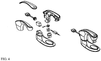
- the power plug 13 may be a common plug shown in FIG. 3 or a clip-type plug 2 with a bulging bag power-off protection function shown in FIG. 4 .
- one or more bolt holes 29 may be connected to the lower part of a threaded section 37 of the connection base 21, one end of a bolt 30 is inserted into the bolt hole 29, and the other end is positioned in a horizontal or longitudinal insertion slot on the threaded sleeve 19 to prevent the threaded sleeve 19 from loosening during use.
- a heatable fluid bag comprises a bag body 1, wherein a liquid inlet 4 and a power access port are formed in the bag body 1, an extractable liquid inlet plunger 3 is installed in the liquid inlet 4, and the power access port is electrically connected with an electrical heating component installed in the bag body 1; the electrical heating component comprises a metal ceramic heating sheet 23, as shown in FIG.
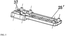
- a wire end of the metal ceramic heating sheet 23 penetrates through a silicone sheet 6 to be located in a protection shell (made of PVC material, metal material, or other materials) composed of an upper base 24' and a lower base 25', one ends of the upper base 24' and the lower base 25' together with the silicone sheet 6 form a sealed wire waterproof insulating sleeve, the other ends of the upper base 24' and the lower base 25' form a sealed or hollow protection sleeve 40 (being of a hollow structure in FIG.
- a protection shell made of PVC material, metal material, or other materials
- a thermal fuse 16 is attached to the metal ceramic heating sheet 23 and is covered with a fuse protection shell 19', and the fuse protection shell 19' is located in the protection sleeve; an upper pressing sheet 11 and a lower pressing sheet 12 are installed in a wire waterproof sleeve, the upper pressing sheet 11 and the lower pressing sheet 12 press the wire end of the metal ceramic heating sheet 23, a silicone sheet 8 is additionally disposed between the upper pressing sheet 11 and the lower pressing sheet 12, the silicone sheet 8 is laterally provided with a hem for preventing lateral leakage, the front surface thereof is provided with two frustum-shaped insertion holes or frustum-shaped wire guide sleeves for wire penetration, the frustum-shaped insertion holes are inserted into conical through holes (non-inverted) in the upper pressing sheet 11, two wires penetrate through the corresponding frustum-shaped insertion holes or frustum-shaped wire guide sleeves in/on the silicone sheet 8 respectively,
- a temperature control switch 17 is installed in the PVC insulation shell 20', a power input socket 15 is also fixed in the PVC insulation shell 20', an upper cover 32 is installed on the power input socket 15 through a screw 34, and a rotary upper cover 14 is installed on the upper cover 32; and a power plug 13 shown in FIG. 3 or a clip-type power plug 2 shown in FIG. 4 can be inserted into the power input socket 15 by rotating the rotary upper cover 14 to expose the power input socket 15 with a square terminal.
- hot water bags in Embodiment 1 and Embodiment 2 may be electrically transformed during the specific implementation, and a communication board is installed in the power connector installation shell 18 for installing the temperature control switch and the thermal fuse additionally, thereby achieving remote control over a mobile phone, monitoring a heating state in real time through an APP, and switching on or off a power supply remotely.
- the metal ceramic heating sheet in Embodiment 1 and Embodiment 2 of the present invention may be rectangular, square, circular, diamond, or of other shapes.
- the metal ceramic heating sheet may also be replaced with other similarly shaped heating elements.
- the metal ceramic heating sheet of the present invention may also be replaced with heating elements having other non-sheet structures or made of other materials even under appropriate and non-creative improvement.
- the heatable fluid bag of the present invention may also be started directly in a frozen state without malfunctioning, and may also be put in a refrigerator for refrigeration to be used as an ice bag.
- Parts not involved in the present invention such as electrical schematic diagrams are the same as those in the prior art or may be implemented by using the prior art, and may also be implemented by referring to Chinese Patent 2013800424341 (or PCT/NZ2013/000162 ).
Landscapes
- Engineering & Computer Science (AREA)
- Physics & Mathematics (AREA)
- Thermal Sciences (AREA)
- Chemical & Material Sciences (AREA)
- Combustion & Propulsion (AREA)
- Mechanical Engineering (AREA)
- General Engineering & Computer Science (AREA)
- Health & Medical Sciences (AREA)
- Vascular Medicine (AREA)
- Heart & Thoracic Surgery (AREA)
- Biomedical Technology (AREA)
- Life Sciences & Earth Sciences (AREA)
- Animal Behavior & Ethology (AREA)
- General Health & Medical Sciences (AREA)
- Public Health (AREA)
- Veterinary Medicine (AREA)
- Resistance Heating (AREA)
- Instantaneous Water Boilers, Portable Hot-Water Supply Apparatuses, And Control Of Portable Hot-Water Supply Apparatuses (AREA)
- Control Of Resistance Heating (AREA)
- Heat-Pump Type And Storage Water Heaters (AREA)
- Thermotherapy And Cooling Therapy Devices (AREA)
Abstract
Description
- The present invention relates to a heating appliance, particularly to an electric liquid (water) heater, and more particularly to a heatable fluid bag.
- At present, an electric hot water bag is a heating appliance commonly used in winter, which has the advantage of fast heating, is convenient to use, can be used for warming the hands, the chest, the abdomen, and other parts, and can also be used for local warming. The electric hot water bag is a device utilizing electricity to heat liquid in a bag. Common heating elements include an electric heating wire, an electric heating tube, and the like, and it is difficult to solve the problem of preventing electric leakage during heating. Because the liquid (mostly tap water) in the bag is easy to infiltrate into electrical components to cause short circuit or electric leakage, electric insulation has always been the focus of attention. However, in actual use, people find that an electric heating element is most likely to malfunction and seriously affect its service life, so finding alternative electric heating elements is the key to ensure the electrical appliance safety, to increase the heating efficiency, and to prolong the service life.
- In recent years, a metal ceramic heating element has been widely applied to water heating. Because of the advantages of water proofing, insulation, electrical appliance safety, small size, high efficiency, and long life, applying the metal ceramic heating element to a liquid heating device (electric hot water bag) has a broad market, and the metal ceramic heating element is an upgraded product that will certainly be favored by people.
- In the present specification, unless explicitly stated to the contrary, where documents, entries, or items of knowledge are referred to or discussed, such reference or discussion is not an admission that the documents, entries, or items of knowledge, or any combination thereof are common knowledge publicly available at a priority date, publicly known and partially known, or are known to attempt to solve any of the problems involved in the present specification.
- The present invention is directed to a heatable fluid device with an electric heating element made of metal ceramics, which is intended to solve the problems of electrical appliance safety such as short service life, low efficiency, large size, and poor waterproof insulation of an electric heating wire, an electric heating tube or other electric heating elements in an existing liquid heating device.
- The first technical solution of the present invention is as follows.
- A heatable fluid bag comprises a
bag body 1, aliquid inlet 4 and apower access port 41 being formed in thebag body 1, an extractableliquid inlet plunger 3 being installed in theliquid inlet 4, and thepower access port 41 being electrically connected with an electrical heating component installed in thebag body 1. The heatable fluid bag is characterized in that the electrical heating component comprises a metalceramic heating sheet 23, the metalceramic heating sheet 23 is encapsulated in a metal protection shell composed of anupper sheet 24 and alower sheet 25, aconnection base 21 is connected onto theupper sheet 24, aPVC protection shell 20 is installed in theconnection base 21, thePVC protection shell 20 and theconnection base 21 are axially positioned through a threadedsleeve 19, an upper end of the threadedsleeve 19 is positioned on thePVC protection shell 20 through anannular boss 31 on thePVC protection shell 20, and a lower end thereof is rotationally installed on a threadedsection 37 of theconnection base 21; a powerconnector installation shell 18 is installed in thePVC protection shell 20, atemperature control switch 17 is installed in the powerconnector installation shell 18, a copper flat-corepower input socket 15 is installed in the powerconnector installation shell 18, and a rotaryupper cover 14 is installed on thepower input socket 15; and an electric wire of the metalceramic heating sheet 23 penetrates through the metal protection shell and theconnection base 21 thereon, then penetrates through thePVC protection shell 20 to enter the powerconnector installation shell 18, then is electrically connected with the temperature control switch and a thermal fuse, and then is electrically connected with thepower input socket 15, and apower plug 13 can be inserted into thepower input socket 15 by rotating the rotary upper cover to expose thepower input socket 15. - The
upper sheet 24 and thelower sheet 25 are provided withannular grooves 35 for installingsealing pads 22, so as to implement a second waterproof and insulated sealing system for the metal ceramic heating sheet, a power wire and a wire lead point; and athermal fuse 16 capable of directly sensing the temperature of the metalceramic heating sheet 23 is installed on theupper sheet 24, the lower part of thePVC protection shell 20 and theupper sheet 24. The lower part of theconnection base 21 is provided with a hollow structure for passage of liquid, so as to directly transfer, via the hollow structure, the temperature of the liquid to thetemperature control switch 17 installed in the power connector installation shell 18 (heat is firstly transferred to a hollow bottom plate of theconnection base 21, then to thePVC protection shell 20, then to the powerconnector installation shell 18 installed in a close fit manner, and finally to the temperature control switch 17). - A power input end of the metal
ceramic heating sheet 23 is provided with anupper pressing sheet 11 and alower pressing sheet 12, theupper pressing sheet 11 is installed in a groove of theupper sheet 24, thelower pressing sheet 12 is installed in agroove 36 of thelower sheet 25, a concave-convex buckle structure is provided on a joint surface of the upper pressing sheet and the lower pressing sheet, and the upper and lower sheets are jointed together by using an ultrasonic process, so as to implement a first waterproof and insulated sealing system for the power wire and the wire lead point; awire sealing pad 27 is additionally disposed between the upper pressingsheet 11 and the metalceramic heating sheet 23, awire guide sleeve 28 for wire penetration is connected to thewire sealing pad 27, thewire guide sleeve 28 penetrates through the upper pressingsheet 11, theupper sheet 24 and thePVC protection shell 20 and is inserted into the powerconnector installation shell 18, a wire led out from the metalceramic heating sheet 23 penetrates through thewire guide sleeve 28 to enter the powerconnector installation shell 18, and is electrically connected with thetemperature control switch 17 and thethermal fuse 16 as well as thepower input socket 15 in sequence, a hole for penetration of the wire guide sleeve in the upper pressing sheet is of a non-inverted cone structure and is inserted into a non-inverted cone hole in the upper sheet, the cone hole in the upper sheet is then inserted into a non-inverted cone hole in thePVC protection shell 20, a cone hole of thePVC protection shell 20 is then inserted into a non-inverted cone hole in the powerconnector installation shell 18, and when the wire guide sleeve 28 passes through each cone hole, multi-stage pressing seal is achieved, and it is ensured that liquid in the bag body cannot enter the powerconnector installation shell 18 along the wire. - The metal
ceramic heating sheet 23 is wound with aninsulating material 26 for insulation. - A
bolt hole 29 is connected to the lower part of the threaded section of theconnection base 21, one end of abolt 30 is inserted into thebolt hole 29, and the other end is positioned in an insertion slot on the threadedsleeve 19 to prevent the threadedsleeve 19 from loosening during use. - The
wire sealing pad 27 is a silicone pad, laterally having a hem for achieving lateral seal during pressing. - The second technical solution of the present invention is as follows.
- A heatable fluid bag comprises a
bag body 1, aliquid inlet 4 and a power access port being formed in thebag body 1, an extractableliquid inlet plunger 3 being installed in theliquid inlet 4, and thepower access port 41 being electrically connected with an electrical heating component installed in thebag body 1. The heatable fluid bag is characterized in that the electrical heating component comprises a metalceramic heating sheet 23, a wire end of the metalceramic heating sheet 23 penetrates through asilicone sheet 6 to be located in a protection shell composed of an upper base 24' and a lower base 25', one ends of the upper base 24' and the lower base 25' together with thesilicone sheet 6 form a sealed wire waterproof insulating sleeve, the other ends of the upper base 24' and the lower base 25' form a sealed or hollow protection sleeve, athermal fuse 16 is attached to theceramic heating sheet 23 and is covered with a fuse protection shell 19', and the fuse protection shell 19' is located in the protection sleeve; an upper pressingsheet 11 and alower pressing sheet 12 are installed in a wire waterproof sleeve, the upper pressingsheet 11 and the lower pressingsheet 12 press the wire end of theceramic heating sheet 23, asilicone sheet 8 is additionally disposed between the upper pressingsheet 11 and theceramic heating sheet 23, thesilicone sheet 8 is provided with a frustum-shaped insertion hole inserted into a through hole in the upperpressing sheet 11, two wires penetrate through the corresponding frustum-shaped insertion holes in thesilicone sheet 8 respectively, are led out from the upperpressing sheet 11, and enter corresponding holes in athreading apparatus 10, the threading apparatus is inserted into a connection base 9 on a PVC insulation shell 20', the connection base 9 is fixed into the wire waterproof insulating sleeve, atemperature control switch 17 is installed in the PVC insulation shell 20', apower input socket 15 is also fixed into the PVC insulation shell 20', and a rotaryupper cover 14 is installed on thepower input socket 15; and apower plug 13 can be inserted into thepower input socket 15 by rotating the rotary upper cover to expose thepower input socket 15 with a square terminal. - The
power plug 13 is a common plug or a clip-type plug 2 with a bulging bag power-off protection function. - The
silicone sheet 8 is laterally provided with a waterproof hem. - An end, inserted into the wire waterproof insulating sleeve, of the connection base 9 is provided with two annular protrusions 7, the annular protrusions 7 being inserted into corresponding insertion slots in the wire waterproof insulating sleeve, so as to position the connection base in the wire waterproof insulating sleeve.
- The present invention has the beneficial effects as follows.
- The present invention adopts multiple waterproof and insulating seals to form at least two independent insulating waterproof systems, and once one system is damaged, at least one system can play a protective role, thereby realizing separation of water and electricity, and completely meeting the requirements of international safety standards for electrical appliances.
- The present invention adopts, but is not limited to, metal ceramics as a heating element, which has the advantages of small heating element size, high thermal efficiency, water proofing, insulation, safety, and long service life. Especially, a metal ceramic heating plate is encapsulated in metal, which is not only limited to a metal protection shell, so that not only the damage of a heating element can be effectively prevented, but also the waterproof effect and the heat transfer effect can be ensured.
- The temperature fuse is used in the present invention to prevent a fire from occurring due to no liquid (water) burning.
- The present invention adopts multiple waterproof and insulating seals to form at least two independent insulating waterproof systems, and once one system is damaged, at least one system can play a protective role, thereby realizing separation of water and electricity, and thoroughly preventing the occurrence of an electric leakage event. In particular, a wire has a silicone sleeve, and a conical threading hole is used to achieve waterproof insulation sealing of the wire.
- The present invention adopts a square electrode pin, which enlarges a contact area between an external power supply and the pin, and can effectively prevent the failure caused by excessive current.
- The electrical installation of the present invention adopts a double-layer protection (close fit between a
PVC protection shell 20 and a power connector installation shell 18), which can ensure the normal operation in the case of one-layer damage, improve the safety, and prolong the service life. -
-
FIG. 1 is a first exploded structure diagram of the present invention. -
FIG. 2 is a second exploded structure diagram of the present invention. -
FIG. 3 is an exploded structure diagram of a power plug of the present invention. -
FIG. 4 is a structure diagram of a clip-type power plug of the present invention. -
FIG. 5 is an enlarged structure diagram of a lower base 25' inFIG. 2 . - The present invention will be further described below with reference to the drawings and embodiments.
- As shown in
FIG. 1 ,FIG. 3 andFIG. 4 ,
a heatable fluid bag comprises abag body 1, wherein aliquid inlet 4 and apower access port 41 are formed in thebag body 1, an extractableliquid inlet plunger 3 is installed in theliquid inlet 4, a waterproof connection between the power access port and thebag body 1 may be implemented by the prior art, and the power access port is electrically connected with an electrical heating component installed in thebag body 1; the electrical heating component comprises a metalceramic heating sheet 23, the metalceramic heating sheet 23 is encapsulated in a metal protection shell composed of anupper sheet 24 and alower sheet 25, theupper sheet 24 and thelower sheet 25 may be fixedly connected through ascrew 33, anannular groove 35 for adding anannular sealing pad 22 is formed in the lower sheet, and a matched annular convex slot is formed on the upper sheet; the metalceramic heating sheet 23 is separated from liquid in thebag body 1 through the annularsilicone sealing pad 22, and moreover, in order to secondarily insulate the metalceramic heating sheet 23, it is necessary to wind a plurality of layers ofinsulating materials 26 before assembly; a power input end of the metalceramic heating sheet 23 is provided with anupper pressing sheet 11 and alower pressing sheet 12, theupper pressing sheet 11 is installed in a groove of theupper sheet 24, thelower pressing sheet 12 is installed in agroove 36 of thelower sheet 25, a concave-convex buckle structure is provided on a joint surface of the upper pressing sheet and the lower pressing sheet, and the upper and lower sheets are jointed together by using an ultrasonic process, so as to implement a waterproof and insulated sealing system for the metal ceramic heating sheet and a wire; and awire sealing pad 27 with a hem (for preventing lateral leakage) is additionally disposed between the upper pressingsheet 11 and the metalceramic heating sheet 23, awire guide sleeve 28 for wire penetration is connected to thewire sealing pad 27, thewire guide sleeve 28 penetrates through the upper pressingsheet 11, theupper sheet 24 and aPVC protection shell 20 and is inserted into a powerconnector installation shell 18, a wire led out from the metalceramic heating sheet 23 penetrates through thewire guide sleeve 28 to enter the powerconnector installation shell 18, and is electrically connected with a temperature control switch 17 (K301) and athermal fuse 16 as well as apower input socket 15 in sequence, a hole for penetration of the wire guide sleeve in the upper pressing sheet is of a non-inverted cone structure and is inserted into a non-inverted cone hole in the upper sheet, the cone hole in the upper sheet is then inserted into a non-inverted cone hole in thePVC protection shell 20, a cone hole of thePVC protection shell 20 is then inserted into a non-inverted cone hole in the powerconnector installation shell 18, and when the wire guide sleeve 28 passes through each cone hole, multi-stage pressing seal is achieved, and it is ensured that the liquid in the bag body cannot enter the powerconnector installation shell 18 along the wire. Aconnection base 21 is connected to theupper sheet 24, thePVC protection shell 20 is installed in theconnection base 21, thePVC protection shell 20 and theconnection base 21 are axially positioned through a threadedsleeve 19, an upper end of the threadedsleeve 19 is positioned on thePVC protection shell 20 through anannular boss 31 on thePVC protection shell 20, and a lower end thereof is rotationally installed on a threadedsection 37 of theconnection base 21. The powerconnector installation shell 18 is installed in thePVC protection shell 20, and thePVC protection shell 20 and the powerconnector installation shell 18 are in close fit, so that when one of theprotection shell 20 and theinstallation shell 18 is damaged, the other one can still normally work. One or twotemperature control switches 17 are installed in the powerconnector installation shell 18, so that when one of the switches is damaged, the other one can still normally work. Thetemperature control switch 17 is attached to the lower part of thePVC protection shell 20 and above a hollow through groove, and can directly sense the temperature of water, and when the temperature of water reaches a set temperature, the temperature control switch is turned off to power off. Thethermal fuse 16 is attached to a solid position of theupper sheet 24 and is located at the lower part of thePVC protection shell 20, so that thethermal fuse 16 directly senses the temperature of the metal ceramic heating sheet to prevent no water burning. In the case of no water burning, the temperature of the upper sheet covering the metalceramic heating sheet 23 is rapidly increased, when the temperature exceeds a set temperature of the thermal fuse, it is necessary to immediately power off, and a product will be scrapped. Thepower input socket 15 is fixedly installed in the powerconnector installation shell 18, anupper cover 32 is installed on thepower input socket 15 through ascrew 34, and a rotaryupper cover 14 is installed on theupper cover 32. An electric wire of the metalceramic heating sheet 23 penetrates through the metal protection shell and theconnection base 21 thereon, then penetrates through thePVC protection shell 20 to enter the powerconnector installation shell 18, then is electrically connected with the temperature control switch and the thermal fuse, and then is electrically connected with thepower input socket 15. Apower plug 13 can be inserted into thepower input socket 15 by rotating the rotary upper cover to expose thepower input socket 15. As shown inFIG. 1 , thepower plug 13 may be a common plug shown inFIG. 3 or a clip-type plug 2 with a bulging bag power-off protection function shown inFIG. 4 . - During specific implementation, in order to prevent the threaded
sleeve 19 from loosening during use, one ormore bolt holes 29 may be connected to the lower part of a threadedsection 37 of theconnection base 21, one end of abolt 30 is inserted into thebolt hole 29, and the other end is positioned in a horizontal or longitudinal insertion slot on the threadedsleeve 19 to prevent the threadedsleeve 19 from loosening during use. - As shown in
FIG. 2 ,FIG. 3 ,FIG. 4 , andFIG. 5 ,
a heatable fluid bag comprises abag body 1, wherein aliquid inlet 4 and a power access port are formed in thebag body 1, an extractableliquid inlet plunger 3 is installed in theliquid inlet 4, and the power access port is electrically connected with an electrical heating component installed in thebag body 1; the electrical heating component comprises a metalceramic heating sheet 23, as shown inFIG. 2 , a wire end of the metalceramic heating sheet 23 penetrates through asilicone sheet 6 to be located in a protection shell (made of PVC material, metal material, or other materials) composed of an upper base 24' and a lower base 25', one ends of the upper base 24' and the lower base 25' together with thesilicone sheet 6 form a sealed wire waterproof insulating sleeve, the other ends of the upper base 24' and the lower base 25' form a sealed or hollow protection sleeve 40 (being of a hollow structure inFIG. 2 , with which the metal ceramic heating sheet is in direct contact with liquid in the bag body for rapid heating), athermal fuse 16 is attached to the metalceramic heating sheet 23 and is covered with a fuse protection shell 19', and the fuse protection shell 19' is located in the protection sleeve; anupper pressing sheet 11 and alower pressing sheet 12 are installed in a wire waterproof sleeve, the upper pressingsheet 11 and thelower pressing sheet 12 press the wire end of the metalceramic heating sheet 23, asilicone sheet 8 is additionally disposed between theupper pressing sheet 11 and thelower pressing sheet 12, thesilicone sheet 8 is laterally provided with a hem for preventing lateral leakage, the front surface thereof is provided with two frustum-shaped insertion holes or frustum-shaped wire guide sleeves for wire penetration, the frustum-shaped insertion holes are inserted into conical through holes (non-inverted) in the upperpressing sheet 11, two wires penetrate through the corresponding frustum-shaped insertion holes or frustum-shaped wire guide sleeves in/on thesilicone sheet 8 respectively, are led out from the upperpressing sheet 11, and enter corresponding holes in athreading apparatus 10, and the threading apparatus is inserted into a connection base 9 on a PVC insulation shell 20'; and an end, inserted into the wire waterproof insulating sleeve, of the connection base 9 is provided with two annular protrusions 7, the annular protrusions 7 being inserted into corresponding insertion slots in the wire waterproof sleeve, so as to position the connection base in the wire waterproof insulating sleeve. Atemperature control switch 17 is installed in the PVC insulation shell 20', apower input socket 15 is also fixed in the PVC insulation shell 20', anupper cover 32 is installed on thepower input socket 15 through ascrew 34, and a rotaryupper cover 14 is installed on theupper cover 32; and apower plug 13 shown inFIG. 3 or a clip-type power plug 2 shown inFIG. 4 can be inserted into thepower input socket 15 by rotating the rotaryupper cover 14 to expose thepower input socket 15 with a square terminal. - In addition, in order to adapt to the development needs of the Internet technology, hot water bags in Embodiment 1 and Embodiment 2 may be electrically transformed during the specific implementation, and a communication board is installed in the power
connector installation shell 18 for installing the temperature control switch and the thermal fuse additionally, thereby achieving remote control over a mobile phone, monitoring a heating state in real time through an APP, and switching on or off a power supply remotely. - Further, the metal ceramic heating sheet in
Embodiment 1 andEmbodiment 2 of the present invention may be rectangular, square, circular, diamond, or of other shapes. The metal ceramic heating sheet may also be replaced with other similarly shaped heating elements. The metal ceramic heating sheet of the present invention may also be replaced with heating elements having other non-sheet structures or made of other materials even under appropriate and non-creative improvement. - Further, the heatable fluid bag of the present invention may also be started directly in a frozen state without malfunctioning, and may also be put in a refrigerator for refrigeration to be used as an ice bag.
- Parts not involved in the present invention such as electrical schematic diagrams are the same as those in the prior art or may be implemented by using the prior art, and may also be implemented by referring to Chinese Patent
2013800424341 PCT/NZ2013/000162
Claims (10)
- A heatable fluid bag, comprising a bag body (1), a liquid inlet (4) and a power access port (41) being formed in the bag body (1), an extractable liquid inlet plunger (3) being installed in the liquid inlet (4), and the power access port (41) being electrically connected with an electrical heating component installed in the bag body (1), characterized in that the electrical heating component comprises a metal ceramic heating sheet (23), the metal ceramic heating sheet (23) is encapsulated in a metal protection shell composed of an upper sheet (24) and a lower sheet (25), a connection base (21) is connected onto the upper sheet (24), a PVC protection shell (20) is installed in the connection base (21), the PVC protection shell (20) and the connection base (21) are axially positioned through a threaded sleeve (19), an upper end of the threaded sleeve (19) is positioned on the PVC protection shell (20) through an annular boss (31) on the PVC protection shell (20), and a lower end thereof is rotationally installed on a threaded section (37) of the connection base (21); a power connector installation shell (18) is installed in the PVC protection shell (20), a temperature control switch (17) is installed in the power connector installation shell (18), a copper flat-core power input socket (15) is installed in the power connector installation shell (18), and a rotary upper cover (14) is installed on the power input socket (15); and a wire of the metal ceramic heating sheet (23) penetrates through the metal protection shell and the connection base (21) thereon, then penetrates through the PVC protection shell (20) to enter the power connector installation shell (18), then is electrically connected with the temperature control switch and a thermal fuse, and then is electrically connected with the power input socket (15), and a power plug (13) can be inserted into the power input socket (15) by rotating the rotary upper cover to expose the power input socket (15).
- The heatable fluid bag according to claim 1, characterized in that the upper sheet (24) and the lower sheet (25) are provided with annular grooves (35) for installing sealing pads (22), so as to implement a second waterproof and insulated sealing system for the metal ceramic heating sheet, a power wire and a wire lead point; a thermal fuse (16) capable of directly sensing the temperature of the metal ceramic heating sheet (23) is installed on the upper sheet (24), the lower part of the PVC protection shell (20) and the upper sheet (24); and the lower part of the connection base (21) is provided with a hollow structure for passage of liquid, so as to directly transfer, via the hollow structure, the temperature of the liquid to the temperature control switch (17) installed in the power connector installation shell (18).
- The heatable fluid bag according to claim 1, characterized in that a power input end of the metal ceramic heating sheet (23) is provided with an upper pressing sheet (11) and a lower pressing sheet (12), the upper pressing sheet (11) is installed in a groove of the upper sheet (24), the lower pressing sheet (12) is installed in a groove (36) of the lower sheet (25), a concave-convex buckle structure is provided on a joint surface of the upper pressing sheet and the lower pressing sheet, and the upper and lower sheets are jointed together by using an ultrasonic process, so as to implement a first waterproof and insulated sealing system for the power wire and the wire lead point; a wire sealing pad (27) is additionally disposed between the upper pressing sheet (11) and the lower pressing sheet (12), a wire guide sleeve (28) for wire penetration is connected to the wire sealing pad (27), the wire guide sleeve (28) penetrates through the upper pressing sheet (11), the upper sheet (24) and the PVC protection shell (20) and is inserted into the power connector installation shell (18), a wire led out from the metal ceramic heating sheet (23) penetrates through the wire guide sleeve (28) to enter the power connector installation shell (18), and is electrically connected with the temperature control switch (17) and the thermal fuse (16) as well as the power input socket (15) in sequence, a hole for penetration of the wire guide sleeve in the upper pressing sheet is of a non-inverted cone structure and is inserted into a non-inverted cone hole in the upper sheet, the cone hole in the upper sheet is then inserted into a non-inverted cone hole in the PVC protection shell (20), a cone hole of the PVC protection shell (20) is then inserted into a non-inverted cone hole in the power connector installation shell (18), and when the wire guide sleeve (28) passes through each cone hole, multi-stage pressing seal is achieved, and it is ensured that liquid in the bag body cannot enter the power connector installation shell (18) along the wire.
- The heatable fluid bag according to claim 1 or claim 4, characterized in that the metal ceramic heating sheet (23) is wound with an insulating material (26) for insulation.
- The heatable fluid bag according to claim 1, characterized in that a bolt hole (29) is connected to the lower part of the threaded section of the connection base (21), one end of a bolt (30) is inserted into the bolt hole (29), and the other end is positioned in an insertion slot on the threaded sleeve (19) to prevent the threaded sleeve (19) from loosening during use.
- The heatable fluid bag according to claim 3, characterized in that the wire sealing pad (27) is a silicone pad, laterally having a hem for achieving lateral seal during pressing.
- A heatable fluid bag, comprising a bag body (1), a liquid inlet (4) and a power access port (41) being formed in the bag body (1), an extractable liquid inlet plunger (3) being installed in the liquid inlet (4), and the power access port (41) being electrically connected with an electrical heating component installed in the bag body (1), characterized in that the electrical heating component comprises a metal ceramic heating sheet (23), a wire end of the metal ceramic heating sheet (23) penetrates through a silicone sheet (6) to be located in a protection shell composed of an upper base (24') and a lower base (25'), one ends of the upper base (24') and the lower base (25') together with the silicone sheet (6) form a sealed wire waterproof insulating sleeve, the other ends of the upper base (24') and the lower base (25') form a sealed or hollow protection sleeve, a thermal fuse (16) is attached to the metal ceramic heating sheet (23) and is covered with a fuse protection shell (19'), and the fuse protection shell (19') is located in the protection sleeve; an upper pressing sheet (11) and a lower pressing sheet (12) are installed in the wire waterproof insulating sleeve, the upper pressing sheet (11) and the lower pressing sheet (12) press the wire end of the metal ceramic heating sheet (23), a silicone sheet (8) is additionally disposed between the upper pressing sheet (11) and the lower pressing sheet (12), the silicone sheet (8) is provided with a frustum-shaped insertion hole inserted into a through hole in the upper pressing sheet (11), two wires penetrate through the corresponding frustum-shaped insertion holes in the silicone sheet (8) respectively, are led out from the upper pressing sheet (11), and enter corresponding holes in a threading apparatus (10), the threading apparatus is inserted into a connection base (9) on a PVC insulation shell (20'), the connection base (9) is fixed into the wire waterproof insulating sleeve, a temperature control switch (17) is installed in the PVC insulation shell (20'), a power input socket (15) is also fixed into the PVC insulation shell (20'), and a rotary upper cover (14) is installed on the power input socket (15); and a power plug (13) can be inserted into the power input socket (15) by rotating the rotary upper cover to expose the power input socket (15) with a square terminal.
- The heatable fluid bag according to claim 1 or claim 7, characterized in that the power plug (13) is a common plug or a clip-type plug (2) with a bulging bag power-off protection function.
- The heatable fluid bag according to claim 7, characterized in that the silicone sheet (8) is laterally provided with a waterproof hem.
- The heatable fluid bag according to claim 7, characterized in that an end, inserted into the wire waterproof insulating sleeve, of the connection base (9) is provided with two annular protrusions (7), the annular protrusions (7) being inserted into corresponding insertion slots in the wire waterproof insulating sleeve, so as to position the connection base in the wire waterproof insulating sleeve.
Applications Claiming Priority (2)
| Application Number | Priority Date | Filing Date | Title |
|---|---|---|---|
| CN201510774117.XA CN105371480B (en) | 2015-11-13 | 2015-11-13 | Heatable fluid pouch |
| PCT/CN2015/094877 WO2017079989A1 (en) | 2015-11-13 | 2015-11-18 | Fluid bag capable of being heated |
Publications (3)
| Publication Number | Publication Date |
|---|---|
| EP3376130A1 true EP3376130A1 (en) | 2018-09-19 |
| EP3376130A4 EP3376130A4 (en) | 2019-07-10 |
| EP3376130B1 EP3376130B1 (en) | 2020-09-16 |
Family
ID=55373906
Family Applications (1)
| Application Number | Title | Priority Date | Filing Date |
|---|---|---|---|
| EP15908119.9A Active EP3376130B1 (en) | 2015-11-13 | 2015-11-18 | Fluid bag capable of being heated |
Country Status (7)
| Country | Link |
|---|---|
| US (1) | US10190800B2 (en) |
| EP (1) | EP3376130B1 (en) |
| JP (1) | JP6670391B2 (en) |
| KR (2) | KR20180125050A (en) |
| CN (1) | CN105371480B (en) |
| CA (1) | CA3004361C (en) |
| WO (1) | WO2017079989A1 (en) |
Families Citing this family (5)
| Publication number | Priority date | Publication date | Assignee | Title |
|---|---|---|---|---|
| CN205286680U (en) * | 2015-12-10 | 2016-06-08 | 上海百来福电器制造有限公司 | Electric heat hot -water bottle |
| CN107348847A (en) * | 2017-05-27 | 2017-11-17 | 何志雄 | Vehicle-mounted coffee maker |
| US10882378B2 (en) * | 2017-08-18 | 2021-01-05 | Zhejiang CFMOTO Power Co., Ltd. | ATV air heat exchanger with mounting structure and linkage |
| US20210169681A1 (en) * | 2019-12-05 | 2021-06-10 | Robert Dempsey | Controlled temperature water bottle |
| US20220218517A1 (en) * | 2021-01-11 | 2022-07-14 | Cheng-Chuan YANG | Health Care Device |
Family Cites Families (26)
| Publication number | Priority date | Publication date | Assignee | Title |
|---|---|---|---|---|
| US6175688B1 (en) * | 1998-07-10 | 2001-01-16 | Belmont Instrument Corporation | Wearable intravenous fluid heater |
| US6788885B2 (en) * | 2000-09-01 | 2004-09-07 | Michael Mitsunaga | System for heating instillation or transfusion liquids |
| US7394976B2 (en) * | 2003-03-25 | 2008-07-01 | Arizant Healthcare Inc. | Fluid warming cassette and system capable of operation under negative pressure |
| US6882797B2 (en) * | 2003-03-26 | 2005-04-19 | Gaymar Industries, Inc. | Multiple plate fluid warmer unit |
| DE102004026446B4 (en) * | 2004-05-29 | 2006-04-20 | WWT Technischer Gerätebau GmbH | Bag warmer for liquid thermal bag |
| US7164852B2 (en) * | 2005-01-11 | 2007-01-16 | Gaymar Industries, Inc. | Fluid reservoir with integrated heater |
| US7563248B2 (en) * | 2005-03-17 | 2009-07-21 | Smisson-Cartledge Biomedical Llc | Infusion fluid heat exchanger and cartridge |
| CN2813943Y (en) * | 2005-06-30 | 2006-09-06 | 朱盈盈 | Cooling and warming fan |
| CN200950663Y (en) * | 2006-08-17 | 2007-09-19 | 苏州市好得电器有限公司 | electric heater unit for electro-thermal water bag |
| CN101319819B (en) | 2007-06-04 | 2011-08-24 | 梁盛权 | Heater and its use method |
| US7720362B2 (en) * | 2007-04-24 | 2010-05-18 | Arizant Healthcare Inc. | Heat exchanger for high flow rate infusion |
| CN201216196Y (en) * | 2008-07-17 | 2009-04-08 | 熊丽 | Health care gloves |
| EP2147690B1 (en) * | 2008-07-25 | 2011-11-09 | WWT Technischer Gerätebau GmbH | Fluid warming bag and bag heater |
| BRPI0918807A2 (en) * | 2008-09-03 | 2015-12-01 | Mcneil Ppc Inc | portable device for combined heat and vibration treatment |
| CN102137519B (en) | 2011-01-12 | 2015-05-27 | 郏帅军 | Heating device of anti-explosion electric hot-water bag |
| CN201910932U (en) * | 2011-01-12 | 2011-07-27 | 郏帅军 | Heating device for anti-explosion electric hot water bottle |
| US20120191164A1 (en) * | 2011-01-26 | 2012-07-26 | Gander Nicholas M | Radiant heating apparatus and method for therapeutic heating |
| CN202759603U (en) * | 2012-08-17 | 2013-02-27 | 泰阳电子(东莞)有限公司 | Ceramic heating device |
| KR20150036324A (en) * | 2012-09-07 | 2015-04-07 | 데이비드 존 아마토 | Heatable fluid bag |
| CN102860899A (en) * | 2012-10-10 | 2013-01-09 | 佛山市顺德区美美创新电器有限公司 | Electric heating hand warmer with ceramic electric heating substrate |
| CN104566935A (en) * | 2013-10-23 | 2015-04-29 | 比亚迪股份有限公司 | Electric heater for liquids |
| EP2925085B1 (en) * | 2014-03-27 | 2018-08-08 | Shengquan Liang | Electric hot water warmer and heating device employing such a warmer |
| JP6204245B2 (en) * | 2014-03-28 | 2017-09-27 | 梁盛權 | Electric hot water bottle and heating device using the electric hot water bottle |
| CN204206489U (en) * | 2014-12-05 | 2015-03-11 | 郏帅军 | The electric-heating hand warmer heater of a kind of anti-dry, preventing water leakage |
| CN104665983B (en) * | 2015-02-15 | 2016-08-17 | 嘉兴三春电器有限公司 | Magnetization warm hand electric calorifie installation |
| CN106377353A (en) | 2016-08-03 | 2017-02-08 | 杨震 | Electric hot water bag |
-
2015
- 2015-11-13 CN CN201510774117.XA patent/CN105371480B/en not_active Expired - Fee Related
- 2015-11-18 KR KR1020187032959A patent/KR20180125050A/en not_active Application Discontinuation
- 2015-11-18 JP JP2018544383A patent/JP6670391B2/en not_active Expired - Fee Related
- 2015-11-18 CA CA3004361A patent/CA3004361C/en active Active
- 2015-11-18 KR KR1020167035446A patent/KR101920397B1/en active IP Right Grant
- 2015-11-18 WO PCT/CN2015/094877 patent/WO2017079989A1/en active Application Filing
- 2015-11-18 EP EP15908119.9A patent/EP3376130B1/en active Active
- 2015-11-18 US US15/770,244 patent/US10190800B2/en not_active Expired - Fee Related
Also Published As
| Publication number | Publication date |
|---|---|
| KR20180125050A (en) | 2018-11-21 |
| EP3376130A4 (en) | 2019-07-10 |
| US10190800B2 (en) | 2019-01-29 |
| JP6670391B2 (en) | 2020-03-18 |
| US20180306465A1 (en) | 2018-10-25 |
| JP2019502088A (en) | 2019-01-24 |
| CN105371480A (en) | 2016-03-02 |
| WO2017079989A1 (en) | 2017-05-18 |
| KR101920397B1 (en) | 2018-11-21 |
| EP3376130B1 (en) | 2020-09-16 |
| CN105371480B (en) | 2018-04-17 |
| KR20170072834A (en) | 2017-06-27 |
| CA3004361A1 (en) | 2017-05-18 |
| CA3004361C (en) | 2020-08-18 |
Similar Documents
| Publication | Publication Date | Title |
|---|---|---|
| CA3004361C (en) | Heatable fluid bag | |
| CN204219139U (en) | A kind of electric hot-water bag anti-dry electro-heat equipment structure-improved | |
| CN206976726U (en) | Socket fire alarm system | |
| CN204390935U (en) | A kind of domestic safety switch | |
| CN205159211U (en) | Hot protector of self -sustaining formula | |
| CN104112623B (en) | A kind of cushion type pressure switch | |
| CN204765004U (en) | Electric pressure cooker with machinery power protection devices | |
| CN209435443U (en) | A kind of electric hot-water bag heating device | |
| CN207320002U (en) | A kind of two-phase liquid expanding high-power temperature control device | |
| CN201968466U (en) | Electric heating kettle | |
| CN109378649A (en) | A kind of safety type power cable | |
| CN105591253A (en) | Plug and socket having fireproof protection apparatus | |
| CN2227306Y (en) | Electric heating pipe with superheat protection | |
| CN204391428U (en) | There is the plug and socket of flameproof protection device | |
| CN204192349U (en) | A kind of electronic temperature-sensing type energy-saving prevention excessive pressure electric cooker | |
| CN201378546Y (en) | Self protective temperature current protector | |
| CN217955753U (en) | Heat dissipation formula heat protector | |
| CN201365818Y (en) | Electric pressure cooking saucepan cover with retractable safety device | |
| CN204132991U (en) | A kind of double warm body blanket | |
| CN202351720U (en) | Temperature sensitivity controller | |
| CN207554955U (en) | A kind of antifreezing faucet | |
| CN202262029U (en) | Circuit board structure | |
| CN203024387U (en) | Light-emitting diode (LED) safe instant-heating type water heater | |
| CN208982774U (en) | A kind of electric hot water tap | |
| PT1243010E (en) | THERMAL SURVEILLANCE DEVICE IN LIGACOES OF ELECTRICAL INSTALLATIONS |
Legal Events
| Date | Code | Title | Description |
|---|---|---|---|
| STAA | Information on the status of an ep patent application or granted ep patent |
Free format text: STATUS: THE INTERNATIONAL PUBLICATION HAS BEEN MADE |
|
| PUAI | Public reference made under article 153(3) epc to a published international application that has entered the european phase |
Free format text: ORIGINAL CODE: 0009012 |
|
| STAA | Information on the status of an ep patent application or granted ep patent |
Free format text: STATUS: REQUEST FOR EXAMINATION WAS MADE |
|
| 17P | Request for examination filed |
Effective date: 20180601 |
|
| AK | Designated contracting states |
Kind code of ref document: A1 Designated state(s): AL AT BE BG CH CY CZ DE DK EE ES FI FR GB GR HR HU IE IS IT LI LT LU LV MC MK MT NL NO PL PT RO RS SE SI SK SM TR |
|
| AX | Request for extension of the european patent |
Extension state: BA ME |
|
| DAV | Request for validation of the european patent (deleted) | ||
| DAX | Request for extension of the european patent (deleted) | ||
| A4 | Supplementary search report drawn up and despatched |
Effective date: 20190613 |
|
| RIC1 | Information provided on ipc code assigned before grant |
Ipc: F24H 9/18 20060101ALI20190606BHEP Ipc: A61F 7/08 20060101ALN20190606BHEP Ipc: A61F 7/00 20060101ALI20190606BHEP Ipc: F24H 1/20 20060101AFI20190606BHEP Ipc: F24H 9/20 20060101ALI20190606BHEP |
|
| GRAP | Despatch of communication of intention to grant a patent |
Free format text: ORIGINAL CODE: EPIDOSNIGR1 |
|
| STAA | Information on the status of an ep patent application or granted ep patent |
Free format text: STATUS: GRANT OF PATENT IS INTENDED |
|
| INTG | Intention to grant announced |
Effective date: 20200506 |
|
| RIC1 | Information provided on ipc code assigned before grant |
Ipc: A61F 7/08 20060101ALN20200421BHEP Ipc: F24H 9/20 20060101ALI20200421BHEP Ipc: F24H 9/18 20060101ALI20200421BHEP Ipc: F24H 1/20 20060101AFI20200421BHEP Ipc: A61F 7/00 20060101ALI20200421BHEP |
|
| GRAS | Grant fee paid |
Free format text: ORIGINAL CODE: EPIDOSNIGR3 |
|
| GRAA | (expected) grant |
Free format text: ORIGINAL CODE: 0009210 |
|
| STAA | Information on the status of an ep patent application or granted ep patent |
Free format text: STATUS: THE PATENT HAS BEEN GRANTED |
|
| AK | Designated contracting states |
Kind code of ref document: B1 Designated state(s): AL AT BE BG CH CY CZ DE DK EE ES FI FR GB GR HR HU IE IS IT LI LT LU LV MC MK MT NL NO PL PT RO RS SE SI SK SM TR |
|
| REG | Reference to a national code |
Ref country code: GB Ref legal event code: FG4D |
|
| REG | Reference to a national code |
Ref country code: CH Ref legal event code: EP |
|
| REG | Reference to a national code |
Ref country code: DE Ref legal event code: R096 Ref document number: 602015059384 Country of ref document: DE |
|
| REG | Reference to a national code |
Ref country code: IE Ref legal event code: FG4D |
|
| REG | Reference to a national code |
Ref country code: AT Ref legal event code: REF Ref document number: 1314513 Country of ref document: AT Kind code of ref document: T Effective date: 20201015 |
|
| PG25 | Lapsed in a contracting state [announced via postgrant information from national office to epo] |
Ref country code: FI Free format text: LAPSE BECAUSE OF FAILURE TO SUBMIT A TRANSLATION OF THE DESCRIPTION OR TO PAY THE FEE WITHIN THE PRESCRIBED TIME-LIMIT Effective date: 20200916 Ref country code: NO Free format text: LAPSE BECAUSE OF FAILURE TO SUBMIT A TRANSLATION OF THE DESCRIPTION OR TO PAY THE FEE WITHIN THE PRESCRIBED TIME-LIMIT Effective date: 20201216 Ref country code: SE Free format text: LAPSE BECAUSE OF FAILURE TO SUBMIT A TRANSLATION OF THE DESCRIPTION OR TO PAY THE FEE WITHIN THE PRESCRIBED TIME-LIMIT Effective date: 20200916 Ref country code: GR Free format text: LAPSE BECAUSE OF FAILURE TO SUBMIT A TRANSLATION OF THE DESCRIPTION OR TO PAY THE FEE WITHIN THE PRESCRIBED TIME-LIMIT Effective date: 20201217 Ref country code: BG Free format text: LAPSE BECAUSE OF FAILURE TO SUBMIT A TRANSLATION OF THE DESCRIPTION OR TO PAY THE FEE WITHIN THE PRESCRIBED TIME-LIMIT Effective date: 20201216 Ref country code: HR Free format text: LAPSE BECAUSE OF FAILURE TO SUBMIT A TRANSLATION OF THE DESCRIPTION OR TO PAY THE FEE WITHIN THE PRESCRIBED TIME-LIMIT Effective date: 20200916 |
|
| REG | Reference to a national code |
Ref country code: AT Ref legal event code: MK05 Ref document number: 1314513 Country of ref document: AT Kind code of ref document: T Effective date: 20200916 |
|
| REG | Reference to a national code |
Ref country code: NL Ref legal event code: MP Effective date: 20200916 |
|
| PG25 | Lapsed in a contracting state [announced via postgrant information from national office to epo] |
Ref country code: LV Free format text: LAPSE BECAUSE OF FAILURE TO SUBMIT A TRANSLATION OF THE DESCRIPTION OR TO PAY THE FEE WITHIN THE PRESCRIBED TIME-LIMIT Effective date: 20200916 Ref country code: RS Free format text: LAPSE BECAUSE OF FAILURE TO SUBMIT A TRANSLATION OF THE DESCRIPTION OR TO PAY THE FEE WITHIN THE PRESCRIBED TIME-LIMIT Effective date: 20200916 |
|
| REG | Reference to a national code |
Ref country code: LT Ref legal event code: MG4D |
|
| PG25 | Lapsed in a contracting state [announced via postgrant information from national office to epo] |
Ref country code: CZ Free format text: LAPSE BECAUSE OF FAILURE TO SUBMIT A TRANSLATION OF THE DESCRIPTION OR TO PAY THE FEE WITHIN THE PRESCRIBED TIME-LIMIT Effective date: 20200916 Ref country code: LT Free format text: LAPSE BECAUSE OF FAILURE TO SUBMIT A TRANSLATION OF THE DESCRIPTION OR TO PAY THE FEE WITHIN THE PRESCRIBED TIME-LIMIT Effective date: 20200916 Ref country code: EE Free format text: LAPSE BECAUSE OF FAILURE TO SUBMIT A TRANSLATION OF THE DESCRIPTION OR TO PAY THE FEE WITHIN THE PRESCRIBED TIME-LIMIT Effective date: 20200916 Ref country code: SM Free format text: LAPSE BECAUSE OF FAILURE TO SUBMIT A TRANSLATION OF THE DESCRIPTION OR TO PAY THE FEE WITHIN THE PRESCRIBED TIME-LIMIT Effective date: 20200916 Ref country code: RO Free format text: LAPSE BECAUSE OF FAILURE TO SUBMIT A TRANSLATION OF THE DESCRIPTION OR TO PAY THE FEE WITHIN THE PRESCRIBED TIME-LIMIT Effective date: 20200916 Ref country code: PT Free format text: LAPSE BECAUSE OF FAILURE TO SUBMIT A TRANSLATION OF THE DESCRIPTION OR TO PAY THE FEE WITHIN THE PRESCRIBED TIME-LIMIT Effective date: 20210118 |
|
| PG25 | Lapsed in a contracting state [announced via postgrant information from national office to epo] |
Ref country code: PL Free format text: LAPSE BECAUSE OF FAILURE TO SUBMIT A TRANSLATION OF THE DESCRIPTION OR TO PAY THE FEE WITHIN THE PRESCRIBED TIME-LIMIT Effective date: 20200916 Ref country code: IS Free format text: LAPSE BECAUSE OF FAILURE TO SUBMIT A TRANSLATION OF THE DESCRIPTION OR TO PAY THE FEE WITHIN THE PRESCRIBED TIME-LIMIT Effective date: 20210116 Ref country code: ES Free format text: LAPSE BECAUSE OF FAILURE TO SUBMIT A TRANSLATION OF THE DESCRIPTION OR TO PAY THE FEE WITHIN THE PRESCRIBED TIME-LIMIT Effective date: 20200916 Ref country code: AL Free format text: LAPSE BECAUSE OF FAILURE TO SUBMIT A TRANSLATION OF THE DESCRIPTION OR TO PAY THE FEE WITHIN THE PRESCRIBED TIME-LIMIT Effective date: 20200916 Ref country code: AT Free format text: LAPSE BECAUSE OF FAILURE TO SUBMIT A TRANSLATION OF THE DESCRIPTION OR TO PAY THE FEE WITHIN THE PRESCRIBED TIME-LIMIT Effective date: 20200916 |
|
| REG | Reference to a national code |
Ref country code: DE Ref legal event code: R097 Ref document number: 602015059384 Country of ref document: DE |
|
| PG25 | Lapsed in a contracting state [announced via postgrant information from national office to epo] |
Ref country code: MC Free format text: LAPSE BECAUSE OF FAILURE TO SUBMIT A TRANSLATION OF THE DESCRIPTION OR TO PAY THE FEE WITHIN THE PRESCRIBED TIME-LIMIT Effective date: 20200916 Ref country code: SK Free format text: LAPSE BECAUSE OF FAILURE TO SUBMIT A TRANSLATION OF THE DESCRIPTION OR TO PAY THE FEE WITHIN THE PRESCRIBED TIME-LIMIT Effective date: 20200916 |
|
| REG | Reference to a national code |
Ref country code: CH Ref legal event code: PL |
|
| PLBE | No opposition filed within time limit |
Free format text: ORIGINAL CODE: 0009261 |
|
| STAA | Information on the status of an ep patent application or granted ep patent |
Free format text: STATUS: NO OPPOSITION FILED WITHIN TIME LIMIT |
|
| PG25 | Lapsed in a contracting state [announced via postgrant information from national office to epo] |
Ref country code: LU Free format text: LAPSE BECAUSE OF NON-PAYMENT OF DUE FEES Effective date: 20201118 |
|
| REG | Reference to a national code |
Ref country code: BE Ref legal event code: MM Effective date: 20201130 |
|
| 26N | No opposition filed |
Effective date: 20210617 |
|
| PG25 | Lapsed in a contracting state [announced via postgrant information from national office to epo] |
Ref country code: DK Free format text: LAPSE BECAUSE OF FAILURE TO SUBMIT A TRANSLATION OF THE DESCRIPTION OR TO PAY THE FEE WITHIN THE PRESCRIBED TIME-LIMIT Effective date: 20200916 Ref country code: CH Free format text: LAPSE BECAUSE OF NON-PAYMENT OF DUE FEES Effective date: 20201130 Ref country code: SI Free format text: LAPSE BECAUSE OF FAILURE TO SUBMIT A TRANSLATION OF THE DESCRIPTION OR TO PAY THE FEE WITHIN THE PRESCRIBED TIME-LIMIT Effective date: 20200916 Ref country code: LI Free format text: LAPSE BECAUSE OF NON-PAYMENT OF DUE FEES Effective date: 20201130 |
|
| PG25 | Lapsed in a contracting state [announced via postgrant information from national office to epo] |
Ref country code: IE Free format text: LAPSE BECAUSE OF NON-PAYMENT OF DUE FEES Effective date: 20201118 Ref country code: IT Free format text: LAPSE BECAUSE OF FAILURE TO SUBMIT A TRANSLATION OF THE DESCRIPTION OR TO PAY THE FEE WITHIN THE PRESCRIBED TIME-LIMIT Effective date: 20200916 |
|
| PG25 | Lapsed in a contracting state [announced via postgrant information from national office to epo] |
Ref country code: TR Free format text: LAPSE BECAUSE OF FAILURE TO SUBMIT A TRANSLATION OF THE DESCRIPTION OR TO PAY THE FEE WITHIN THE PRESCRIBED TIME-LIMIT Effective date: 20200916 Ref country code: MT Free format text: LAPSE BECAUSE OF FAILURE TO SUBMIT A TRANSLATION OF THE DESCRIPTION OR TO PAY THE FEE WITHIN THE PRESCRIBED TIME-LIMIT Effective date: 20200916 Ref country code: CY Free format text: LAPSE BECAUSE OF FAILURE TO SUBMIT A TRANSLATION OF THE DESCRIPTION OR TO PAY THE FEE WITHIN THE PRESCRIBED TIME-LIMIT Effective date: 20200916 |
|
| PG25 | Lapsed in a contracting state [announced via postgrant information from national office to epo] |
Ref country code: MK Free format text: LAPSE BECAUSE OF FAILURE TO SUBMIT A TRANSLATION OF THE DESCRIPTION OR TO PAY THE FEE WITHIN THE PRESCRIBED TIME-LIMIT Effective date: 20200916 |
|
| PG25 | Lapsed in a contracting state [announced via postgrant information from national office to epo] |
Ref country code: BE Free format text: LAPSE BECAUSE OF NON-PAYMENT OF DUE FEES Effective date: 20201130 |
|
| PGFP | Annual fee paid to national office [announced via postgrant information from national office to epo] |
Ref country code: GB Payment date: 20220531 Year of fee payment: 7 Ref country code: FR Payment date: 20220531 Year of fee payment: 7 Ref country code: DE Payment date: 20220531 Year of fee payment: 7 |
|
| REG | Reference to a national code |
Ref country code: DE Ref legal event code: R119 Ref document number: 602015059384 Country of ref document: DE |
|
| PG25 | Lapsed in a contracting state [announced via postgrant information from national office to epo] |
Ref country code: NL Free format text: LAPSE BECAUSE OF NON-PAYMENT OF DUE FEES Effective date: 20200923 |
|
| GBPC | Gb: european patent ceased through non-payment of renewal fee |
Effective date: 20221118 |
|
| PG25 | Lapsed in a contracting state [announced via postgrant information from national office to epo] |
Ref country code: GB Free format text: LAPSE BECAUSE OF NON-PAYMENT OF DUE FEES Effective date: 20221118 Ref country code: DE Free format text: LAPSE BECAUSE OF NON-PAYMENT OF DUE FEES Effective date: 20230601 |
|
| PG25 | Lapsed in a contracting state [announced via postgrant information from national office to epo] |
Ref country code: FR Free format text: LAPSE BECAUSE OF NON-PAYMENT OF DUE FEES Effective date: 20221130 |