EP3376015A1 - Air cleaner for internal combustion engine - Google Patents
Air cleaner for internal combustion engine Download PDFInfo
- Publication number
- EP3376015A1 EP3376015A1 EP18152879.5A EP18152879A EP3376015A1 EP 3376015 A1 EP3376015 A1 EP 3376015A1 EP 18152879 A EP18152879 A EP 18152879A EP 3376015 A1 EP3376015 A1 EP 3376015A1
- Authority
- EP
- European Patent Office
- Prior art keywords
- secondary air
- wall
- chamber
- cleaner
- separate chamber
- Prior art date
- Legal status (The legal status is an assumption and is not a legal conclusion. Google has not performed a legal analysis and makes no representation as to the accuracy of the status listed.)
- Granted
Links
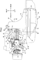
Images



Classifications
-
- F—MECHANICAL ENGINEERING; LIGHTING; HEATING; WEAPONS; BLASTING
- F02—COMBUSTION ENGINES; HOT-GAS OR COMBUSTION-PRODUCT ENGINE PLANTS
- F02M—SUPPLYING COMBUSTION ENGINES IN GENERAL WITH COMBUSTIBLE MIXTURES OR CONSTITUENTS THEREOF
- F02M35/00—Combustion-air cleaners, air intakes, intake silencers, or induction systems specially adapted for, or arranged on, internal-combustion engines
- F02M35/02—Air cleaners
- F02M35/024—Air cleaners using filters, e.g. moistened
-
- F—MECHANICAL ENGINEERING; LIGHTING; HEATING; WEAPONS; BLASTING
- F01—MACHINES OR ENGINES IN GENERAL; ENGINE PLANTS IN GENERAL; STEAM ENGINES
- F01N—GAS-FLOW SILENCERS OR EXHAUST APPARATUS FOR MACHINES OR ENGINES IN GENERAL; GAS-FLOW SILENCERS OR EXHAUST APPARATUS FOR INTERNAL-COMBUSTION ENGINES
- F01N3/00—Exhaust or silencing apparatus having means for purifying, rendering innocuous, or otherwise treating exhaust
- F01N3/08—Exhaust or silencing apparatus having means for purifying, rendering innocuous, or otherwise treating exhaust for rendering innocuous
- F01N3/10—Exhaust or silencing apparatus having means for purifying, rendering innocuous, or otherwise treating exhaust for rendering innocuous by thermal or catalytic conversion of noxious components of exhaust
- F01N3/24—Exhaust or silencing apparatus having means for purifying, rendering innocuous, or otherwise treating exhaust for rendering innocuous by thermal or catalytic conversion of noxious components of exhaust characterised by constructional aspects of converting apparatus
- F01N3/30—Arrangements for supply of additional air
-
- F—MECHANICAL ENGINEERING; LIGHTING; HEATING; WEAPONS; BLASTING
- F01—MACHINES OR ENGINES IN GENERAL; ENGINE PLANTS IN GENERAL; STEAM ENGINES
- F01N—GAS-FLOW SILENCERS OR EXHAUST APPARATUS FOR MACHINES OR ENGINES IN GENERAL; GAS-FLOW SILENCERS OR EXHAUST APPARATUS FOR INTERNAL-COMBUSTION ENGINES
- F01N3/00—Exhaust or silencing apparatus having means for purifying, rendering innocuous, or otherwise treating exhaust
- F01N3/08—Exhaust or silencing apparatus having means for purifying, rendering innocuous, or otherwise treating exhaust for rendering innocuous
- F01N3/10—Exhaust or silencing apparatus having means for purifying, rendering innocuous, or otherwise treating exhaust for rendering innocuous by thermal or catalytic conversion of noxious components of exhaust
- F01N3/24—Exhaust or silencing apparatus having means for purifying, rendering innocuous, or otherwise treating exhaust for rendering innocuous by thermal or catalytic conversion of noxious components of exhaust characterised by constructional aspects of converting apparatus
- F01N3/30—Arrangements for supply of additional air
- F01N3/303—Filtering additional air
-
- F—MECHANICAL ENGINEERING; LIGHTING; HEATING; WEAPONS; BLASTING
- F01—MACHINES OR ENGINES IN GENERAL; ENGINE PLANTS IN GENERAL; STEAM ENGINES
- F01N—GAS-FLOW SILENCERS OR EXHAUST APPARATUS FOR MACHINES OR ENGINES IN GENERAL; GAS-FLOW SILENCERS OR EXHAUST APPARATUS FOR INTERNAL-COMBUSTION ENGINES
- F01N3/00—Exhaust or silencing apparatus having means for purifying, rendering innocuous, or otherwise treating exhaust
- F01N3/08—Exhaust or silencing apparatus having means for purifying, rendering innocuous, or otherwise treating exhaust for rendering innocuous
- F01N3/10—Exhaust or silencing apparatus having means for purifying, rendering innocuous, or otherwise treating exhaust for rendering innocuous by thermal or catalytic conversion of noxious components of exhaust
- F01N3/24—Exhaust or silencing apparatus having means for purifying, rendering innocuous, or otherwise treating exhaust for rendering innocuous by thermal or catalytic conversion of noxious components of exhaust characterised by constructional aspects of converting apparatus
- F01N3/30—Arrangements for supply of additional air
- F01N3/34—Arrangements for supply of additional air using air conduits or jet air pumps, e.g. near the engine exhaust port
-
- F—MECHANICAL ENGINEERING; LIGHTING; HEATING; WEAPONS; BLASTING
- F02—COMBUSTION ENGINES; HOT-GAS OR COMBUSTION-PRODUCT ENGINE PLANTS
- F02M—SUPPLYING COMBUSTION ENGINES IN GENERAL WITH COMBUSTIBLE MIXTURES OR CONSTITUENTS THEREOF
- F02M35/00—Combustion-air cleaners, air intakes, intake silencers, or induction systems specially adapted for, or arranged on, internal-combustion engines
- F02M35/10—Air intakes; Induction systems
- F02M35/10209—Fluid connections to the air intake system; their arrangement of pipes, valves or the like
- F02M35/10222—Exhaust gas recirculation [EGR]; Positive crankcase ventilation [PCV]; Additional air admission, lubricant or fuel vapour admission
-
- F—MECHANICAL ENGINEERING; LIGHTING; HEATING; WEAPONS; BLASTING
- F02—COMBUSTION ENGINES; HOT-GAS OR COMBUSTION-PRODUCT ENGINE PLANTS
- F02M—SUPPLYING COMBUSTION ENGINES IN GENERAL WITH COMBUSTIBLE MIXTURES OR CONSTITUENTS THEREOF
- F02M35/00—Combustion-air cleaners, air intakes, intake silencers, or induction systems specially adapted for, or arranged on, internal-combustion engines
- F02M35/14—Combined air cleaners and silencers
-
- F—MECHANICAL ENGINEERING; LIGHTING; HEATING; WEAPONS; BLASTING
- F02—COMBUSTION ENGINES; HOT-GAS OR COMBUSTION-PRODUCT ENGINE PLANTS
- F02M—SUPPLYING COMBUSTION ENGINES IN GENERAL WITH COMBUSTIBLE MIXTURES OR CONSTITUENTS THEREOF
- F02M35/00—Combustion-air cleaners, air intakes, intake silencers, or induction systems specially adapted for, or arranged on, internal-combustion engines
- F02M35/16—Combustion-air cleaners, air intakes, intake silencers, or induction systems specially adapted for, or arranged on, internal-combustion engines characterised by use in vehicles
- F02M35/162—Motorcycles; All-terrain vehicles, e.g. quads, snowmobiles; Small vehicles, e.g. forklifts
-
- Y—GENERAL TAGGING OF NEW TECHNOLOGICAL DEVELOPMENTS; GENERAL TAGGING OF CROSS-SECTIONAL TECHNOLOGIES SPANNING OVER SEVERAL SECTIONS OF THE IPC; TECHNICAL SUBJECTS COVERED BY FORMER USPC CROSS-REFERENCE ART COLLECTIONS [XRACs] AND DIGESTS
- Y02—TECHNOLOGIES OR APPLICATIONS FOR MITIGATION OR ADAPTATION AGAINST CLIMATE CHANGE
- Y02T—CLIMATE CHANGE MITIGATION TECHNOLOGIES RELATED TO TRANSPORTATION
- Y02T10/00—Road transport of goods or passengers
- Y02T10/10—Internal combustion engine [ICE] based vehicles
- Y02T10/12—Improving ICE efficiencies
Definitions
- the present invention relates to an air cleaner for an internal combustion engine comprising a secondary air conduit that has a downstream end portion and an upstream end portion, a secondary air valve being interposed at an intermediate portion of the secondary air conduit, the downstream end portion being coupled to an exhaust system, the upstream end portion being coupled to a cleaner case so as to be communicated with an inside of a purified chamber.
- Patent Document 1 A secondary air valve disposed in an intermediate portion of a secondary air passage coupled to an exhaust passage of an internal combustion engine has been known by Patent Document 1.
- Patent Document 1 Japanese Patent Application Laid-open No. 2008-19710
- the secondary air valve disclosed in Patent Document 1 has a special structure to achieve a reduction in operating noise occurred during an actuation of the secondary air valve, resulting in cost increase.
- the present invention has been made in consideration of such circumstance and an object of the present invention is to provide an air cleaner for an internal combustion engine that ensures suppressing noise in association with the actuation of the secondary air valve from leaking to outside without using the secondary air valve with the special structure.
- an air cleaner for an internal combustion engine comprising a secondary air conduit that has a downstream end portion and an upstream end portion, a secondary air valve being interposed at an intermediate portion of the secondary air conduit, the downstream end portion being coupled to an exhaust system, the upstream end portion being coupled to a cleaner case so as to be communicated with an inside of a purified chamber, characterized in that in the purified chamber, a region including a coupling portion of the purified chamber which is coupled with the secondary air conduit is partitioned as a secondary air separate chamber occupying a part of the purified chamber.
- a connecting tube that guides air to an engine body side is coupled to the cleaner case, and the connecting tube has an upstream end opening in the purified chamber, the upstream end opening being arranged between a cleaner element and the secondary air separate chamber, the cleaner element being interposed between the purified chamber and an unpurified chamber.
- the secondary air separate chamber has a wall surface a part of which is formed of the cleaner case.
- a blow-by gas separate chamber into which blow-by gas is introduced is formed adjacent to the secondary air separate chamber.
- a partition wall constitutes the secondary air separate chamber and the blow-by gas separate chamber in cooperation with the cleaner case, the partition wall being bonded to a protruding portion protruded from an inner surface of the cleaner case.
- the partition wall has a shared wall portion shared by the secondary air separate chamber and the blow-by gas separate chamber, and the shared wall portion is arranged at a position separating the secondary air separate chamber and the blow-by gas separate chamber from each other.
- the secondary air conduit is communicated with the secondary air separate chamber partitioned in the purified chamber so as to occupy a part of the inside of the purified chamber. Therefore, echoes of an operating noise of the secondary air valve in the air cleaner can be suppressed. This ensures suppressing noise in association with an actuation of the secondary air valve from leaking to the outside without the use of a secondary air valve with a special structure.
- the upstream end opening of the connecting tube in the purified chamber is present between the cleaner element and the secondary air separate chamber. Accordingly, the secondary air separate chamber does not block a flow of air purified through the cleaner element to the connecting tube, thereby ensuring smoothing the flow of the air to the connecting tube.
- a part of a wall surface of the secondary air separate chamber is constituted of a part of the cleaner case. Accordingly, an increase in weight of the air cleaner caused by disposing the secondary air separate chamber can be suppressed.
- the blow-by gas separate chamber and the secondary air separate chamber are formed adjacent to one another in the purified chamber. Accordingly, between the blow-by gas separate chamber and the secondary air separate chamber, a part of the wall thereof can be used in common, thereby ensuring simplification and weight reduction of the structure.
- the partition wall for constituting the secondary air separate chamber and the blow-by gas separate chamber is bonded to the protruding portion protruded from the inner surface of the cleaner case. This ensures contributing to improvement in rigidity of the cleaner case.
- the shared wall portion as a part of the partition wall separates the secondary air separate chamber and the blow-by gas separate chamber from each other. Accordingly, the use of the partition wall with the simple shape allows forming the secondary air separate chamber and the blow-by gas separate chamber in the cleaner case.
- a body frame F of a scooter type two-wheeled motor vehicle includes a head pipe 13, a down frame 14, a pair of left and right main frames 15, a pair of left and right lower frames 16, a pair of left and right seat frames 17, and a pair of left and right rear frames 18.
- the head pipe 13 steerably supports a front fork 11, which journals a front wheel WF, and a steering handlebar 12 coupled to the front fork 11.
- the down frame 14 extends downward from this head pipe 13.
- the pair of left and right main frames 15 branch from the upper portion of this down frame 14 to the left and right and extend downward to the rear.
- the pair of left and right lower frames 16 are connected to the lower portion of the down frame 14 and extend rearward, and the rear end portions of the lower frames 16 are connected to the lower end portions of the main frames 15.
- the pair of left and right seat frames 17 are connected to the intermediate portions of the main frames 15 and extend upward to the rear.
- the pair of left and right rear frames 18 couple the rear end portions of the lower frames 16 to the seat frames 17 and extend upward to the rear.
- the lower frames 16 and the rear frames 18 are integrally formed.
- a bracket 19 is disposed at the front end portion of the rear frame 18 in the body frame F.
- a power unit P providing power to drive a rear wheel WR is supported to be swingable in the up-down direction via a link mechanism 20.
- the power unit P is constituted of a water-cooled internal combustion engine E, which is arranged in front of the rear wheel WR, and a power transmission device M, which transmits an output from this internal combustion engine E to the rear wheel WR.
- the power transmission device M is housed in a transmission case 25 connected to an engine body 22 of the internal combustion engine E and extending on the left side of the rear wheel WR.
- a rear cushion unit 26 is disposed between the rear portion of this transmission case 25 and the rear portion of the body frame F.
- a fuel tank 27 is arranged in front of the power unit P so as to be supported by the down frame 14 and the lower frames 16 of the body frame F.
- a radiator 28 is arranged between the fuel tank 27 and the power unit P as seen in the side view of the vehicle.
- a canister 29 is arranged on the left side of the fuel tank 27.
- a part of the power unit P and the body frame F are covered with a vehicle body cover 30, which includes a pair of left and right footrests 31 on which feet of the occupant are stepped and a floor tunnel portion 32 bulging upward between these footrests 31.
- This vehicle body cover 30 is mounted to the body frame F.
- An occupant seat 35 and a passenger seat 36 which is arranged at the rear of the occupant seat 35, are disposed at the rear of the floor tunnel portion 32 and on the vehicle body cover 30.
- the engine body 22 in the internal combustion engine E has a posture inclined forward until the posture becomes substantially horizontal.
- An intake system 37 is coupled to an upper sidewall of a cylinder head 23 constituting a part of this engine body 22, and an exhaust system 38 is coupled to the lower sidewall of the cylinder head 23.
- the intake system 37 includes an air cleaner 39, a connecting tube 40, a throttle body 41, and an insulator 42.
- the air cleaner 39 is supported to the transmission case 25 of the power unit P and is arranged on the upper side of this transmission case 25.
- the upstream end portion of the connecting tube 40 is coupled to the air cleaner 39.
- the downstream end portion of this connecting tube 40 is coupled to the throttle body 41.
- the insulator 42 couples this throttle body 41 and the cylinder head 23.
- a fuel injection valve 43 is mounted to the cylinder head 23.
- the exhaust system 38 includes an exhaust pipe 44 and an exhaust muffler 45.
- the upstream end portion of the exhaust pipe 44 is coupled to the lower sidewall of the cylinder head 23, and the exhaust pipe 44 is extended rearward through the lower side of the engine body 22.
- the exhaust muffler 45 is arranged on the right side of the rear wheel WR and is coupled to the downstream end portion of the exhaust pipe 44.
- the downstream end portion of a secondary air conduit 46 is coupled to the exhaust pipe 44 on the upstream side with respect to the exhaust muffler 45 in the exhaust system 38, and the upstream end portion of this secondary air conduit 46 is coupled to the air cleaner 39.
- a secondary air valve 47 is interposed at the intermediate portion of the secondary air conduit 46. That is, the secondary air conduit 46 is constituted of a downstream conduit 48, which couples the exhaust pipe 44 and the secondary air valve 47, and an upstream conduit 49, which couples the air cleaner 39 and the secondary air valve 47. Both the downstream conduit 48 and the upstream conduit 49 are hoses.
- a blow-by gas conduit 50 which guides blow-by gas from a crankcase 24 of the engine body 22, is disposed between the crankcase 24 and the air cleaner 39.
- This blow-by gas conduit 50 is also a hose and is disposed to intersect in the up-down direction with the upstream conduit 49 of the secondary air conduit 46.
- the air cleaner 39 includes a cleaner case 53, an element support plate 54, and a cleaner element 55.
- the cleaner case 53 is formed of a case body 51 made of synthetic resin and a case cover 52, which is dividingly combined with this case body 51 from the left side in the vehicle width direction.
- the element support plate 54 is clamped between the case body 51 and the case cover 52.
- the cleaner element 55 is disposed at the element support plate 54.
- An unpurified chamber 56 is formed between the element support plate 54, the cleaner element 55, and the case cover 52.
- a purified chamber 57 is formed between the element support plate 54, the cleaner element 55, and the case body 51.
- the case body 51 is formed into a shape open to the left side in the vehicle width direction, arranged upward the transmission case 25, and is supported to the upper portion of the transmission case 25.
- the element support plate 54 integrally includes an element support portion 54a, which is formed into a rectangular tube shape so as to house and support the cleaner element 55. The outer peripheral edge portion of the element support plate 54 is clamped and secured between the case body 51 and the case cover 52.
- a cover member 59 made of synthetic resin to form an air introduction chamber 58 open to the outside is mounted to the front portion of the case cover 52.
- a suction duct 60 which communicates between the air introduction chamber 58 and the unpurified chamber 56 and airtightly passes through the front wall portion of the case cover 52, is supported to the front wall portion of the case cover 52.
- the case body 51 integrally includes a bottomed tubular portion 61 with the closed right side end portion thereof in the vehicle width direction.
- the tubular portion 61 has a front wall 61a, which is inclined downward to the front, a rear wall 61b, which is arranged from the front wall 61a rearward in the vehicle front-rear direction and inclined downward to the front, a ceiling wall 61c, which couples the upper end portions of the front wall 61a and the rear wall 61b, a bottom wall 61d, which couples the lower end portions of the front wall 61a and the rear wall 61b, and an end wall 61e, which couples right end portions of the front wall 61a, the rear wall 61b, the ceiling wall 61c, and the bottom wall 61d in the vehicle width direction.
- a region including the coupling portion of the purified chamber 57 which is coupled with the upstream conduit 49 of the secondary air conduit 46 is partitioned as a secondary air separate chamber 62, which occupies a part of the purified chamber 57.
- a blow-by gas separate chamber 63 into which the blow-by gas is introduced is formed adjacent to the secondary air separate chamber 62.
- a first protruding wall 64, a second protruding wall 65, and a rod-shaped protruding portion 66 are integrally provided in a protruding manner.
- the first protruding wall 64 is inclined downward to the rear and connects between the intermediate portion in the up-down direction of the front wall 61a and the bottom wall 61d.
- the second protruding wall 65 is arranged parallel to the first protruding wall 64 rearward in the vehicle front-rear direction with respect to the first protruding wall 64 and connects between a part biased to the upper portion of the front wall 61a in the up-down direction and the bottom wall 61d.
- the rod-shaped protruding portion 66 is integrated with the first protruding wall 64 and protrudes on the right side in the vehicle width direction from the first protruding wall 64.
- the secondary air separate chamber 62 and the blow-by gas separate chamber 63 are formed by cooperation of a partition wall 67, which is a member different from the case body 51, and the tubular portion 61 in the case body 51 of the cleaner case 53.
- the partition wall 67 integrally has a flat outside wall portion 67a, a rear side wall portion 67b, an inside wall portion 67c, and a reinforcing plate portion 67d.
- the outside wall portion 67a abuts against the tip end portions of the first protruding wall 64 and the second protruding wall 65 to form the blow-by gas separate chamber 63 between the first protruding wall 64 and the second protruding wall 65.
- the rear side wall portion 67b is connected at a right angle to the rear end of the outside wall portion 67a in the vehicle front-rear direction and extends to the left side in the vehicle width direction.
- the inside wall portion 67c is connected at a right angle to the left end portion of the rear side wall portion 67b in the vehicle width direction, extends forward in the vehicle front-rear direction, and abuts against the front wall 61a of the case body 51.
- the reinforcing plate portion 67d is arranged upright on the inner surface of the rear side wall portion 67b, extending between the rear portions of the outside wall portion 67a and the inside wall portion 67c.
- the upper end portion of the partition wall 67 abuts against the front wall 61a of the tubular portion 61, and the lower end portion of the partition wall 67 abuts against the lower portion of the rear wall 61b and the bottom wall 61d of the tubular portion 61.
- the secondary air separate chamber 62 is formed by the end wall 61e, the front wall 61a, the bottom wall 61d, and the rear wall 61b of the tubular portion 61, the first protruding wall 64, and the partition wall 67 in the case body 51.
- a part of the wall surface of the secondary air separate chamber 62 is formed of the tubular portion 61 in the case body 51 of the cleaner case 53.
- the blow-by gas separate chamber 63 is formed by the end wall 61e, the front wall 61a, the bottom wall 61d, and the rear wall 61b of the tubular portion 61, the first protruding wall 64, the second protruding wall 65, and the outside wall portion 67a of the partition wall 67 in the case body 51.
- the blow-by gas separate chamber 63 is arranged adjacent to the secondary air separate chamber 62. That is, the outside wall portion 67a as a part of the partition wall 67 functions as a shared wall portion shared by the secondary air separate chamber 62 and the blow-by gas separate chamber 63, and this outside wall portion 67a is arranged at a position separating the secondary air separate chamber 62 and the blow-by gas separate chamber 63 from each other.
- a through hole 68 into which the tip end portion of the protruding portion 66 is inserted is formed in the inside wall portion 67c of the partition wall 67.
- the protruding portion 66 is bonded to the inside wall portion 67c of the partition wall 67 by thermal crimping.
- a blow-by gas coupling pipe 69 and a secondary air coupling pipe 70 are integrally provided in a protruding manner forward in the vehicle front-rear direction.
- the blow-by gas coupling pipe 69 opens between the first protruding wall 64 and the second protruding wall 65 so as to be communicated with the blow-by gas separate chamber 63.
- the secondary air coupling pipe 70 is arranged on the left side of the blow-by gas coupling pipe 69 in the vehicle width direction and is communicated with the secondary air separate chamber 62.
- the blow-by gas conduit 50 is coupled to the blow-by gas coupling pipe 69 and the upstream conduit 49 of the secondary air conduit 46 is coupled to the secondary air coupling pipe 70.
- An opening 71 is formed at the central portion in the vehicle width direction of the front wall 61a of the tubular portion 61 in the case body 51 so as to be positioned on the left side in the vehicle width direction with respect to the secondary air coupling pipe 70.
- the connecting tube 40 which guides the air to the cylinder head 23 side of the engine body 22, airtightly passes through the opening 71 and is coupled to the front wall 61a.
- An upstream end opening 40a of the connecting tube 40 in the purified chamber 57 orients the cleaner element 55 side, the cleaner element 55 being interposed between the unpurified chamber 56 and the purified chamber 57, and is arranged between this cleaner element 55 and the secondary air separate chamber 62.
- a plurality of secondary air communication holes 72 are formed in the rear side wall portion 67b of the partition wall 67 to guide the air inside the purified chamber 57 to the secondary air separate chamber 62.
- a blow-by gas communication hole 73 is formed in the upper portion of the second protruding wall 65 to cause the upper portion inside the blow-by gas separate chamber 63 to be communicated with the inside of the purified chamber 57.
- a drain hole 74 communicating with the lower portion of the blow-by gas separate chamber 63 is disposed at the end wall 61e of the tubular portion 61, this drain hole 74 may be omitted.
- the region including the coupling portion of the purified chamber 57 which is coupled with the secondary air conduit 46 is partitioned as the secondary air separate chamber 62 occupying a part of the purified chamber 57. Therefore, echoes of the operating noise of the secondary air valve 47 interposed at the intermediate portion of the secondary air conduit 46 can be suppressed in the air cleaner 39. This ensures suppressing the noise in association with the actuation of the secondary air valve 47 from leaking to the outside without the use of the secondary air valve 47 with the special structure.
- the connecting tube 40 to guide the air to the cylinder head 23 side of the engine body 22 is coupled to the front wall 61a of the tubular portion 61 in the case body 51 of the cleaner case 53.
- the upstream end opening 40a of the connecting tube 40 in the purified chamber 57 is arranged between the cleaner element 55, which is interposed between the purified chamber 57 and the unpurified chamber 56, and the secondary air separate chamber 62. Accordingly, the secondary air separate chamber 62 does not block the flow of the air purified through the cleaner element 55 to the connecting tube 40, thereby ensuring smoothing the flow of the air to the connecting tube 40.
- a part of the wall surface of the secondary air separate chamber 62 is formed of the tubular portion 61 in the case body 51 of the cleaner case 53. Accordingly, an increase in weight of the air cleaner 39 caused by disposing the secondary air separate chamber 62 can be suppressed.
- the blow-by gas separate chamber 63 into which the blow-by gas is introduced is formed adjacent to the secondary air separate chamber 62. Accordingly, between the blow-by gas separate chamber 63 and the secondary air separate chamber 62, a part of the wall thereof can be used in common, thereby ensuring simplification and weight reduction of the structure.
- the partition wall 67 which constitutes the secondary air separate chamber 62 and the blow-by gas separate chamber 63 in cooperation with the tubular portion 61 in the case body 51 of the cleaner case 53, is bonded to the protruding portion 66 protruded from the inner surface of the end wall 61e at the tubular portion 61. This ensures contributing to improvement in rigidity of the case body 51 and eventually the cleaner case 53.
- the partition wall 67 has the outside wall portion 67a as the shared wall portion shared by the secondary air separate chamber 62 and the blow-by gas separate chamber 63.
- the outside wall portion 67a is arranged at the position separating the secondary air separate chamber 62 and the blow-by gas separate chamber 63 from each other. Accordingly, the use of the partition wall 67 with the simple shape allows forming the secondary air separate chamber 62 and the blow-by gas separate chamber 63 in the cleaner case 53.
- An air cleaner 76 includes a cleaner case 78, the element support plate 54, and the cleaner element 55.
- the cleaner case 78 is formed of a case body 77 made of synthetic resin and the case cover 52, which is dividingly combined with this case body 77 from the left side in the vehicle width direction.
- the element support plate 54 is clamped between the case body 77 and the case cover 52.
- the cleaner element 55 is disposed at the element support plate 54.
- the unpurified chamber 56 is formed between the element support plate 54, the cleaner element 55, and the case cover 52.
- the purified chamber 57 is formed between the element support plate 54, the cleaner element 55, and the case body 77.
- the outer peripheral edge portion of the element support plate 54 is clamped and secured between the case body 77 and the case cover 52.
- the case body 77 integrally includes a bottomed tubular portion 81 with the closed right side end portion thereof in the vehicle width direction.
- the tubular portion 81 has: a front wall 81a, which is inclined downward to the front; a rear wall 81b, which is arranged from the front wall 81a rearward in the vehicle front-rear direction and inclined downward to the front; a ceiling wall 81c, which couples the upper end portions of the front wall 81a and the rear wall 81b; a bottom wall 81d, which couples the lower end portions of the front wall 81a and the rear wall 81b; and an end wall 81e, which couples right end portions of the front wall 81a, the rear wall 81b, the ceiling wall 81c, and the bottom wall 81d in the vehicle width direction.
- a region including the coupling portion of the purified chamber 57 which is coupled with the upstream conduit 49 of the secondary air conduit 46 is partitioned as a secondary air separate chamber 82, which occupies a part of the purified chamber 57.
- a blow-by gas separate chamber 83 into which the blow-by gas is introduced is formed adjacent to the secondary air separate chamber 82.
- a protruding wall 84 is integrally provided in a protruding manner on the inner surface of the end wall 81e of the tubular portion 81 in the case body 77 of the cleaner case 78.
- the protruding wall 84 is formed into a flat plate shape extending along the vehicle front-rear direction and the vehicle width direction and connects between the intermediate portion in the up-down direction of the front wall 81a and the intermediate portion in the up-down direction of the rear wall 81b.
- a rod-shaped protruding portion 86 is integrally provided in a protruding manner.
- the rod-shaped protruding portion 86 is arranged above the protruding wall 84 and projects on the right side in the vehicle width direction
- the secondary air separate chamber 82 and the blow-by gas separate chamber 83 are formed by cooperation of a partition wall 87 which is a member different from the case body 77, and the tubular portion 81 in the case body 77 of the cleaner case 78.
- the partition wall 87 integrally has a flat plate-shaped lower wall portion 87a, a flat plate-shaped inside wall portion 87b, a flat plate-shaped intermediate wall portion 87c, and a flat plate-shaped outside wall portion 87d.
- the outer end of the lower wall portion 87a in the vehicle width direction is caused to abut against the tip end of the protruding wall 84, and the lower wall portion 87a extends along the vehicle front-rear direction and the vehicle width direction.
- the inside wall portion 87b is connected at a right angle to an end portion, on the side opposite to the protruding wall 84, of the lower wall portion 87a and extends along the up-down direction and the vehicle front-rear direction.
- the intermediate wall portion 87c is connected at a right angle to the intermediate portion of the lower wall portion 87a and the inside wall portion 87b in the vehicle front-rear direction and extends along the up-down direction and the vehicle width direction.
- the outside wall portion 87d is connected at a right angle to the end portion of the lower wall portion 87a, the end portion being on the side opposite to the inside wall portion 87b forward with respect to the intermediate wall portion 87c in the vehicle front-rear direction.
- the outside wall portion 87d is also connected at a right angle to the end portion, on the side opposite to the inside wall portion 87b, of the intermediate wall portion 87c and extends along the vehicle front-rear direction and the up-down direction.
- the front end edge and the rear end edge of the lower wall portion 87a are caused to abut against the front wall 81a and the rear wall 81b of the tubular portion 81.
- the front end edge, the rear end edge, and the upper end edge of the inside wall portion 87b are caused to abut against the front wall 81a, the rear wall 81b, and the ceiling wall 81c of the tubular portion 81, respectively.
- the upper end edge of the intermediate wall portion 87c is caused to abut against the ceiling wall 81c of the tubular portion 81.
- the front end edge and the upper end edge of the outside wall portion 87d are caused to abut against the front wall 81a and the ceiling wall 81c of the tubular portion 81.
- the secondary air separate chamber 82 is formed of the end wall 81e, the front wall 81a, the rear wall 81b, and the ceiling wall 81c of the tubular portion 81, and the protruding wall 84, and the lower wall portion 87a, the inside wall portion 87b, the intermediate wall portion 87c, and the outside wall portion 87d of the partition wall 87, in the case body 77, so as to have a shape bent into a substantially L shape as seen in a plan view.
- a part of the wall surface of the secondary air separate chamber 82 is formed by the tubular portion 81 in the case body 77 of the cleaner case 78.
- the blow-by gas separate chamber 83 is formed of the front wall 81a of the tubular portion 81, and the lower wall portion 87a, the inside wall portion 87b, the intermediate wall portion 87c, and the outside wall portion 87d of the partition wall 87, in the case body 77.
- the blow-by gas separate chamber 83 is arranged adjacent to the secondary air separate chamber 82 so as to be covered with this secondary air separate chamber 82 from rearward in the vehicle front-rear direction and outward in the vehicle width direction.
- the intermediate wall portion 87c and the outside wall portion 87d as a part of the partition wall 87 are configured as a shared wall portion 88 shared by the secondary air separate chamber 82 and the blow-by gas separate chamber 83.
- This shared wall portion 88 is arranged at the position separating the secondary air separate chamber 82 and the blow-by gas separate chamber 83 from each other.
- a through hole 94 into which the tip end portion of the protruding portion 86 is inserted is formed on the inside wall portion 87b of the partition wall 87.
- the protruding portion 86 is bonded to the inside wall portion 87b of the partition wall 87 by thermal crimping.
- a blow-by gas coupling pipe 89 and a secondary air coupling pipe 90 are integrally provided in a protruding manner forward in the vehicle front-rear direction.
- the blow-by gas coupling pipe 89 is communicated with the lower portion inside the blow-by gas separate chamber 83.
- the secondary air coupling pipe 90 is arranged on the right side of the blow-by gas coupling pipe 89 in the vehicle width direction and communicated with the upper portion of the secondary air separate chamber 82.
- the blow-by gas conduit 50 substantially linearly extending in the vehicle front-rear direction as seen in a plan view is coupled.
- the upstream conduit 49 of the secondary air conduit 46 substantially linearly extending in the vehicle front-rear direction as seen in a plan view is coupled.
- the opening 71 is formed at the central portion in the vehicle width direction of the front wall 81a of the tubular portion 81 in the case body 77 so as to be positioned on the left side with respect to the blow-by gas coupling pipe 89 in the vehicle width direction.
- the connecting tube 40 airtightly passes through the opening 71 and is coupled to the front wall 81a.
- the upstream end opening 40a of the connecting tube 40 in the purified chamber 57 orients the cleaner element 55 side, the cleaner element 55 being interposed between the unpurified chamber 56 and the purified chamber 57, and is arranged between this cleaner element 55 and the secondary air separate chamber 82.
- a plurality of secondary air communication holes 92 are formed on the lower wall portion 87a of the partition wall 87 so as to guide the air inside the purified chamber 57 to the secondary air separate chamber 82.
- a cutout 93 is formed on the front end upper portion of the inside wall portion 87b in the partition wall 87 so as to cause the upper portion inside the blow-by gas separate chamber 83 to be communicated with the inside of the purified chamber 57.
- This second embodiment can also provide the effects similar to the first embodiment.
Landscapes
- Engineering & Computer Science (AREA)
- Chemical & Material Sciences (AREA)
- Combustion & Propulsion (AREA)
- Mechanical Engineering (AREA)
- General Engineering & Computer Science (AREA)
- Chemical Kinetics & Catalysis (AREA)
- Health & Medical Sciences (AREA)
- Toxicology (AREA)
- Exhaust Gas After Treatment (AREA)
- Lubrication Details And Ventilation Of Internal Combustion Engines (AREA)
Abstract
Description
- The present invention relates to an air cleaner for an internal combustion engine comprising a secondary air conduit that has a downstream end portion and an upstream end portion, a secondary air valve being interposed at an intermediate portion of the secondary air conduit, the downstream end portion being coupled to an exhaust system, the upstream end portion being coupled to a cleaner case so as to be communicated with an inside of a purified chamber.
- A secondary air valve disposed in an intermediate portion of a secondary air passage coupled to an exhaust passage of an internal combustion engine has been known by Patent Document 1.
- Patent Document 1: Japanese Patent Application Laid-open No.
2008-19710 - The secondary air valve disclosed in Patent Document 1 has a special structure to achieve a reduction in operating noise occurred during an actuation of the secondary air valve, resulting in cost increase.
- The present invention has been made in consideration of such circumstance and an object of the present invention is to provide an air cleaner for an internal combustion engine that ensures suppressing noise in association with the actuation of the secondary air valve from leaking to outside without using the secondary air valve with the special structure.
- In order to achieve the object, according to a first feature of the present invention, there is provided an air cleaner for an internal combustion engine comprising a secondary air conduit that has a downstream end portion and an upstream end portion, a secondary air valve being interposed at an intermediate portion of the secondary air conduit, the downstream end portion being coupled to an exhaust system, the upstream end portion being coupled to a cleaner case so as to be communicated with an inside of a purified chamber, characterized in that in the purified chamber, a region including a coupling portion of the purified chamber which is coupled with the secondary air conduit is partitioned as a secondary air separate chamber occupying a part of the purified chamber.
- According to a second feature, in addition to the first feature, a connecting tube that guides air to an engine body side is coupled to the cleaner case, and the connecting tube has an upstream end opening in the purified chamber, the upstream end opening being arranged between a cleaner element and the secondary air separate chamber, the cleaner element being interposed between the purified chamber and an unpurified chamber.
- According to a third feature, in addition to the first feature or the second feature, the secondary air separate chamber has a wall surface a part of which is formed of the cleaner case.
- According to a fourth feature, in addition to any one of the first feature to the third feature, in the purified chamber, a blow-by gas separate chamber into which blow-by gas is introduced is formed adjacent to the secondary air separate chamber.
- According to a fifth feature, in addition to the fourth feature, a partition wall constitutes the secondary air separate chamber and the blow-by gas separate chamber in cooperation with the cleaner case, the partition wall being bonded to a protruding portion protruded from an inner surface of the cleaner case.
- According to a sixth feature, in addition to the fifth feature, the partition wall has a shared wall portion shared by the secondary air separate chamber and the blow-by gas separate chamber, and the shared wall portion is arranged at a position separating the secondary air separate chamber and the blow-by gas separate chamber from each other.
- According to the first feature of the present invention, the secondary air conduit is communicated with the secondary air separate chamber partitioned in the purified chamber so as to occupy a part of the inside of the purified chamber. Therefore, echoes of an operating noise of the secondary air valve in the air cleaner can be suppressed. This ensures suppressing noise in association with an actuation of the secondary air valve from leaking to the outside without the use of a secondary air valve with a special structure.
- According to the second feature of the present invention, the upstream end opening of the connecting tube in the purified chamber is present between the cleaner element and the secondary air separate chamber. Accordingly, the secondary air separate chamber does not block a flow of air purified through the cleaner element to the connecting tube, thereby ensuring smoothing the flow of the air to the connecting tube.
- According to the third feature of the present invention, a part of a wall surface of the secondary air separate chamber is constituted of a part of the cleaner case. Accordingly, an increase in weight of the air cleaner caused by disposing the secondary air separate chamber can be suppressed.
- According to the fourth feature of the present invention, the blow-by gas separate chamber and the secondary air separate chamber are formed adjacent to one another in the purified chamber. Accordingly, between the blow-by gas separate chamber and the secondary air separate chamber, a part of the wall thereof can be used in common, thereby ensuring simplification and weight reduction of the structure.
- According to the fifth feature of the present invention, the partition wall for constituting the secondary air separate chamber and the blow-by gas separate chamber is bonded to the protruding portion protruded from the inner surface of the cleaner case. This ensures contributing to improvement in rigidity of the cleaner case.
- According to the sixth feature of the present invention, the shared wall portion as a part of the partition wall separates the secondary air separate chamber and the blow-by gas separate chamber from each other. Accordingly, the use of the partition wall with the simple shape allows forming the secondary air separate chamber and the blow-by gas separate chamber in the cleaner case.
-
- [
FIG. 1 ] It is a left side view of a two-wheeled motor vehicle of a first embodiment. - [
FIG. 2 ] It is a plan view of an internal combustion engine. - [
FIG. 3 ] It is a drawing illustrating a passage configuration of an intake system and an exhaust system of the internal combustion engine. - [
FIG. 4 ] It is a sectional view taken along a line 4-4 inFIG. 2 . - [
FIG. 5 ] It is a sectional view taken along a line 5-5 inFIG. 4 . - [
FIG. 6 ] It is a sectional view taken along a line 6-6 inFIG. 2 . - [
FIG. 7 ] It is a sectional view corresponding toFIG. 4 of a second embodiment. - [
FIG. 8 ] It is a sectional view taken along a line 8-8 inFIG. 7 . - [
FIG. 9 ] It is a sectional view taken along a line 9-9 inFIG. 8 . - The following describes embodiments of the present invention referring to the accompanying drawings. The following description defines the up, down, right, left, front, and rear, as directions viewed from an occupant riding on a two-wheeled motor vehicle.
- The following describes a first embodiment of the present invention with reference to
FIG. 1 to FIG. 6 . First, inFIG. 1 , a body frame F of a scooter type two-wheeled motor vehicle includes ahead pipe 13, adown frame 14, a pair of left and rightmain frames 15, a pair of left and rightlower frames 16, a pair of left andright seat frames 17, and a pair of left and rightrear frames 18. Thehead pipe 13 steerably supports a front fork 11, which journals a front wheel WF, and asteering handlebar 12 coupled to the front fork 11. Thedown frame 14 extends downward from thishead pipe 13. The pair of left and rightmain frames 15 branch from the upper portion of this downframe 14 to the left and right and extend downward to the rear. The pair of left and rightlower frames 16 are connected to the lower portion of thedown frame 14 and extend rearward, and the rear end portions of thelower frames 16 are connected to the lower end portions of themain frames 15. The pair of left andright seat frames 17 are connected to the intermediate portions of themain frames 15 and extend upward to the rear. The pair of left and rightrear frames 18 couple the rear end portions of thelower frames 16 to theseat frames 17 and extend upward to the rear. Thelower frames 16 and therear frames 18 are integrally formed. - A
bracket 19 is disposed at the front end portion of therear frame 18 in the body frame F. A power unit P providing power to drive a rear wheel WR is supported to be swingable in the up-down direction via alink mechanism 20. The power unit P is constituted of a water-cooled internal combustion engine E, which is arranged in front of the rear wheel WR, and a power transmission device M, which transmits an output from this internal combustion engine E to the rear wheel WR. The power transmission device M is housed in atransmission case 25 connected to anengine body 22 of the internal combustion engine E and extending on the left side of the rear wheel WR. Arear cushion unit 26 is disposed between the rear portion of thistransmission case 25 and the rear portion of the body frame F. - A
fuel tank 27 is arranged in front of the power unit P so as to be supported by thedown frame 14 and thelower frames 16 of the body frameF. A radiator 28 is arranged between thefuel tank 27 and the power unit P as seen in the side view of the vehicle. Acanister 29 is arranged on the left side of thefuel tank 27. - A part of the power unit P and the body frame F are covered with a
vehicle body cover 30, which includes a pair of left andright footrests 31 on which feet of the occupant are stepped and afloor tunnel portion 32 bulging upward between thesefootrests 31. Thisvehicle body cover 30 is mounted to the body frame F. Anoccupant seat 35 and apassenger seat 36, which is arranged at the rear of theoccupant seat 35, are disposed at the rear of thefloor tunnel portion 32 and on thevehicle body cover 30. - With reference to
FIG. 2 andFIG. 3 as well, theengine body 22 in the internal combustion engine E has a posture inclined forward until the posture becomes substantially horizontal. Anintake system 37 is coupled to an upper sidewall of acylinder head 23 constituting a part of thisengine body 22, and anexhaust system 38 is coupled to the lower sidewall of thecylinder head 23. - The
intake system 37 includes anair cleaner 39, aconnecting tube 40, athrottle body 41, and aninsulator 42. Theair cleaner 39 is supported to thetransmission case 25 of the power unit P and is arranged on the upper side of thistransmission case 25. The upstream end portion of the connectingtube 40 is coupled to theair cleaner 39. The downstream end portion of this connectingtube 40 is coupled to thethrottle body 41. Theinsulator 42 couples thisthrottle body 41 and thecylinder head 23. Afuel injection valve 43 is mounted to thecylinder head 23. Theexhaust system 38 includes anexhaust pipe 44 and anexhaust muffler 45. The upstream end portion of theexhaust pipe 44 is coupled to the lower sidewall of thecylinder head 23, and theexhaust pipe 44 is extended rearward through the lower side of theengine body 22. Theexhaust muffler 45 is arranged on the right side of the rear wheel WR and is coupled to the downstream end portion of theexhaust pipe 44. - Especially focusing on
FIG. 3 , the downstream end portion of asecondary air conduit 46 is coupled to theexhaust pipe 44 on the upstream side with respect to theexhaust muffler 45 in theexhaust system 38, and the upstream end portion of thissecondary air conduit 46 is coupled to theair cleaner 39. Moreover, asecondary air valve 47 is interposed at the intermediate portion of thesecondary air conduit 46. That is, thesecondary air conduit 46 is constituted of adownstream conduit 48, which couples theexhaust pipe 44 and thesecondary air valve 47, and anupstream conduit 49, which couples theair cleaner 39 and thesecondary air valve 47. Both thedownstream conduit 48 and theupstream conduit 49 are hoses. A blow-bygas conduit 50, which guides blow-by gas from acrankcase 24 of theengine body 22, is disposed between thecrankcase 24 and theair cleaner 39. This blow-bygas conduit 50 is also a hose and is disposed to intersect in the up-down direction with theupstream conduit 49 of thesecondary air conduit 46. - With reference to
FIG. 4 to FIG. 6 as well, theair cleaner 39 includes acleaner case 53, anelement support plate 54, and acleaner element 55. Thecleaner case 53 is formed of acase body 51 made of synthetic resin and acase cover 52, which is dividingly combined with thiscase body 51 from the left side in the vehicle width direction. Theelement support plate 54 is clamped between thecase body 51 and thecase cover 52. Thecleaner element 55 is disposed at theelement support plate 54. Anunpurified chamber 56 is formed between theelement support plate 54, thecleaner element 55, and thecase cover 52. Apurified chamber 57 is formed between theelement support plate 54, thecleaner element 55, and thecase body 51. - The
case body 51 is formed into a shape open to the left side in the vehicle width direction, arranged upward thetransmission case 25, and is supported to the upper portion of thetransmission case 25. Theelement support plate 54 integrally includes anelement support portion 54a, which is formed into a rectangular tube shape so as to house and support thecleaner element 55. The outer peripheral edge portion of theelement support plate 54 is clamped and secured between thecase body 51 and thecase cover 52. - To the front portion of the
case cover 52, acover member 59 made of synthetic resin to form anair introduction chamber 58 open to the outside is mounted. Asuction duct 60, which communicates between theair introduction chamber 58 and theunpurified chamber 56 and airtightly passes through the front wall portion of thecase cover 52, is supported to the front wall portion of thecase cover 52. - The
case body 51 integrally includes a bottomedtubular portion 61 with the closed right side end portion thereof in the vehicle width direction. Thetubular portion 61 has afront wall 61a, which is inclined downward to the front, arear wall 61b, which is arranged from thefront wall 61a rearward in the vehicle front-rear direction and inclined downward to the front, aceiling wall 61c, which couples the upper end portions of thefront wall 61a and therear wall 61b, abottom wall 61d, which couples the lower end portions of thefront wall 61a and therear wall 61b, and anend wall 61e, which couples right end portions of thefront wall 61a, therear wall 61b, theceiling wall 61c, and thebottom wall 61d in the vehicle width direction. - According to the present invention, in the purified
chamber 57, a region including the coupling portion of the purifiedchamber 57 which is coupled with theupstream conduit 49 of thesecondary air conduit 46 is partitioned as a secondary airseparate chamber 62, which occupies a part of the purifiedchamber 57. In the purifiedchamber 57, a blow-by gasseparate chamber 63 into which the blow-by gas is introduced is formed adjacent to the secondary airseparate chamber 62. - On the inner surface of the
end wall 61e of thetubular portion 61 in thecase body 51 of thecleaner case 53, a first protrudingwall 64, a second protrudingwall 65, and a rod-shaped protrudingportion 66 are integrally provided in a protruding manner. The first protrudingwall 64 is inclined downward to the rear and connects between the intermediate portion in the up-down direction of thefront wall 61a and thebottom wall 61d. The second protrudingwall 65 is arranged parallel to the first protrudingwall 64 rearward in the vehicle front-rear direction with respect to the first protrudingwall 64 and connects between a part biased to the upper portion of thefront wall 61a in the up-down direction and thebottom wall 61d. The rod-shaped protrudingportion 66 is integrated with the first protrudingwall 64 and protrudes on the right side in the vehicle width direction from the first protrudingwall 64. - The secondary air
separate chamber 62 and the blow-by gasseparate chamber 63 are formed by cooperation of apartition wall 67, which is a member different from thecase body 51, and thetubular portion 61 in thecase body 51 of thecleaner case 53. Thepartition wall 67 integrally has a flatoutside wall portion 67a, a rearside wall portion 67b, aninside wall portion 67c, and a reinforcingplate portion 67d. Theoutside wall portion 67a abuts against the tip end portions of the first protrudingwall 64 and the second protrudingwall 65 to form the blow-by gasseparate chamber 63 between the first protrudingwall 64 and the second protrudingwall 65. The rearside wall portion 67b is connected at a right angle to the rear end of theoutside wall portion 67a in the vehicle front-rear direction and extends to the left side in the vehicle width direction. Theinside wall portion 67c is connected at a right angle to the left end portion of the rearside wall portion 67b in the vehicle width direction, extends forward in the vehicle front-rear direction, and abuts against thefront wall 61a of thecase body 51. The reinforcingplate portion 67d is arranged upright on the inner surface of the rearside wall portion 67b, extending between the rear portions of theoutside wall portion 67a and theinside wall portion 67c. Moreover, the upper end portion of thepartition wall 67 abuts against thefront wall 61a of thetubular portion 61, and the lower end portion of thepartition wall 67 abuts against the lower portion of therear wall 61b and thebottom wall 61d of thetubular portion 61. - That is, the secondary air
separate chamber 62 is formed by theend wall 61e, thefront wall 61a, thebottom wall 61d, and therear wall 61b of thetubular portion 61, the first protrudingwall 64, and thepartition wall 67 in thecase body 51. A part of the wall surface of the secondary airseparate chamber 62 is formed of thetubular portion 61 in thecase body 51 of thecleaner case 53. The blow-by gasseparate chamber 63 is formed by theend wall 61e, thefront wall 61a, thebottom wall 61d, and therear wall 61b of thetubular portion 61, the first protrudingwall 64, the second protrudingwall 65, and theoutside wall portion 67a of thepartition wall 67 in thecase body 51. The blow-by gasseparate chamber 63 is arranged adjacent to the secondary airseparate chamber 62. That is, theoutside wall portion 67a as a part of thepartition wall 67 functions as a shared wall portion shared by the secondary airseparate chamber 62 and the blow-by gasseparate chamber 63, and thisoutside wall portion 67a is arranged at a position separating the secondary airseparate chamber 62 and the blow-by gasseparate chamber 63 from each other. - A through
hole 68 into which the tip end portion of the protrudingportion 66 is inserted is formed in theinside wall portion 67c of thepartition wall 67. The protrudingportion 66 is bonded to theinside wall portion 67c of thepartition wall 67 by thermal crimping. - At the
front wall 61a of thetubular portion 61 in thecase body 51, a blow-bygas coupling pipe 69 and a secondaryair coupling pipe 70 are integrally provided in a protruding manner forward in the vehicle front-rear direction. The blow-bygas coupling pipe 69 opens between the first protrudingwall 64 and the second protrudingwall 65 so as to be communicated with the blow-by gasseparate chamber 63. The secondaryair coupling pipe 70 is arranged on the left side of the blow-bygas coupling pipe 69 in the vehicle width direction and is communicated with the secondary airseparate chamber 62. The blow-bygas conduit 50 is coupled to the blow-bygas coupling pipe 69 and theupstream conduit 49 of thesecondary air conduit 46 is coupled to the secondaryair coupling pipe 70. - An
opening 71 is formed at the central portion in the vehicle width direction of thefront wall 61a of thetubular portion 61 in thecase body 51 so as to be positioned on the left side in the vehicle width direction with respect to the secondaryair coupling pipe 70. Moreover, the connectingtube 40, which guides the air to thecylinder head 23 side of theengine body 22, airtightly passes through theopening 71 and is coupled to thefront wall 61a. An upstream end opening 40a of the connectingtube 40 in the purifiedchamber 57 orients thecleaner element 55 side, thecleaner element 55 being interposed between theunpurified chamber 56 and the purifiedchamber 57, and is arranged between thiscleaner element 55 and the secondary airseparate chamber 62. - A plurality of secondary air communication holes 72 are formed in the rear
side wall portion 67b of thepartition wall 67 to guide the air inside the purifiedchamber 57 to the secondary airseparate chamber 62. A blow-bygas communication hole 73 is formed in the upper portion of the second protrudingwall 65 to cause the upper portion inside the blow-by gasseparate chamber 63 to be communicated with the inside of the purifiedchamber 57. Further, while adrain hole 74 communicating with the lower portion of the blow-by gasseparate chamber 63 is disposed at theend wall 61e of thetubular portion 61, thisdrain hole 74 may be omitted. - Next, describing the operation of this first embodiment, in the purified
chamber 57, which is formed in thecleaner case 53 of theair cleaner 39, the region including the coupling portion of the purifiedchamber 57 which is coupled with thesecondary air conduit 46 is partitioned as the secondary airseparate chamber 62 occupying a part of the purifiedchamber 57. Therefore, echoes of the operating noise of thesecondary air valve 47 interposed at the intermediate portion of thesecondary air conduit 46 can be suppressed in theair cleaner 39. This ensures suppressing the noise in association with the actuation of thesecondary air valve 47 from leaking to the outside without the use of thesecondary air valve 47 with the special structure. - The connecting
tube 40 to guide the air to thecylinder head 23 side of theengine body 22 is coupled to thefront wall 61a of thetubular portion 61 in thecase body 51 of thecleaner case 53. The upstream end opening 40a of the connectingtube 40 in the purifiedchamber 57 is arranged between thecleaner element 55, which is interposed between thepurified chamber 57 and theunpurified chamber 56, and the secondary airseparate chamber 62. Accordingly, the secondary airseparate chamber 62 does not block the flow of the air purified through thecleaner element 55 to the connectingtube 40, thereby ensuring smoothing the flow of the air to the connectingtube 40. - A part of the wall surface of the secondary air
separate chamber 62 is formed of thetubular portion 61 in thecase body 51 of thecleaner case 53. Accordingly, an increase in weight of theair cleaner 39 caused by disposing the secondary airseparate chamber 62 can be suppressed. - Additionally, in the purified
chamber 57, the blow-by gasseparate chamber 63 into which the blow-by gas is introduced is formed adjacent to the secondary airseparate chamber 62. Accordingly, between the blow-by gasseparate chamber 63 and the secondary airseparate chamber 62, a part of the wall thereof can be used in common, thereby ensuring simplification and weight reduction of the structure. - The
partition wall 67, which constitutes the secondary airseparate chamber 62 and the blow-by gasseparate chamber 63 in cooperation with thetubular portion 61 in thecase body 51 of thecleaner case 53, is bonded to the protrudingportion 66 protruded from the inner surface of theend wall 61e at thetubular portion 61. This ensures contributing to improvement in rigidity of thecase body 51 and eventually thecleaner case 53. - Further, the
partition wall 67 has theoutside wall portion 67a as the shared wall portion shared by the secondary airseparate chamber 62 and the blow-by gasseparate chamber 63. Theoutside wall portion 67a is arranged at the position separating the secondary airseparate chamber 62 and the blow-by gasseparate chamber 63 from each other. Accordingly, the use of thepartition wall 67 with the simple shape allows forming the secondary airseparate chamber 62 and the blow-by gasseparate chamber 63 in thecleaner case 53. - The following describes a second embodiment of the present invention with reference to
FIG. 7 to FIG. 9 . The parts corresponding to the first embodiment are merely illustrated by assigning the identical reference numerals and therefore are not elaborated here. - An
air cleaner 76 includes acleaner case 78, theelement support plate 54, and thecleaner element 55. Thecleaner case 78 is formed of acase body 77 made of synthetic resin and thecase cover 52, which is dividingly combined with thiscase body 77 from the left side in the vehicle width direction. Theelement support plate 54 is clamped between thecase body 77 and thecase cover 52. Thecleaner element 55 is disposed at theelement support plate 54. Theunpurified chamber 56 is formed between theelement support plate 54, thecleaner element 55, and thecase cover 52. The purifiedchamber 57 is formed between theelement support plate 54, thecleaner element 55, and thecase body 77. The outer peripheral edge portion of theelement support plate 54 is clamped and secured between thecase body 77 and thecase cover 52. - The
case body 77 integrally includes a bottomedtubular portion 81 with the closed right side end portion thereof in the vehicle width direction. Thetubular portion 81 has: afront wall 81a, which is inclined downward to the front; arear wall 81b, which is arranged from thefront wall 81a rearward in the vehicle front-rear direction and inclined downward to the front; aceiling wall 81c, which couples the upper end portions of thefront wall 81a and therear wall 81b; abottom wall 81d, which couples the lower end portions of thefront wall 81a and therear wall 81b; and anend wall 81e, which couples right end portions of thefront wall 81a, therear wall 81b, theceiling wall 81c, and thebottom wall 81d in the vehicle width direction. - In the purified
chamber 57, a region including the coupling portion of the purifiedchamber 57 which is coupled with theupstream conduit 49 of thesecondary air conduit 46 is partitioned as a secondary airseparate chamber 82, which occupies a part of the purifiedchamber 57. In the purifiedchamber 57, a blow-by gasseparate chamber 83 into which the blow-by gas is introduced is formed adjacent to the secondary airseparate chamber 82. - A protruding
wall 84 is integrally provided in a protruding manner on the inner surface of theend wall 81e of thetubular portion 81 in thecase body 77 of thecleaner case 78. The protrudingwall 84 is formed into a flat plate shape extending along the vehicle front-rear direction and the vehicle width direction and connects between the intermediate portion in the up-down direction of thefront wall 81a and the intermediate portion in the up-down direction of therear wall 81b. On an inner surface at the intermediate portion in the front-rear direction of theend wall 81e, a rod-shaped protrudingportion 86 is integrally provided in a protruding manner. The rod-shaped protrudingportion 86 is arranged above the protrudingwall 84 and projects on the right side in the vehicle width direction - The secondary air
separate chamber 82 and the blow-by gasseparate chamber 83 are formed by cooperation of apartition wall 87 which is a member different from thecase body 77, and thetubular portion 81 in thecase body 77 of thecleaner case 78. - The
partition wall 87 integrally has a flat plate-shapedlower wall portion 87a, a flat plate-shaped insidewall portion 87b, a flat plate-shapedintermediate wall portion 87c, and a flat plate-shaped outsidewall portion 87d. The outer end of thelower wall portion 87a in the vehicle width direction is caused to abut against the tip end of the protrudingwall 84, and thelower wall portion 87a extends along the vehicle front-rear direction and the vehicle width direction. Theinside wall portion 87b is connected at a right angle to an end portion, on the side opposite to the protrudingwall 84, of thelower wall portion 87a and extends along the up-down direction and the vehicle front-rear direction. Theintermediate wall portion 87c is connected at a right angle to the intermediate portion of thelower wall portion 87a and theinside wall portion 87b in the vehicle front-rear direction and extends along the up-down direction and the vehicle width direction. Theoutside wall portion 87d is connected at a right angle to the end portion of thelower wall portion 87a, the end portion being on the side opposite to theinside wall portion 87b forward with respect to theintermediate wall portion 87c in the vehicle front-rear direction. Theoutside wall portion 87d is also connected at a right angle to the end portion, on the side opposite to theinside wall portion 87b, of theintermediate wall portion 87c and extends along the vehicle front-rear direction and the up-down direction. - Moreover, the front end edge and the rear end edge of the
lower wall portion 87a are caused to abut against thefront wall 81a and therear wall 81b of thetubular portion 81. The front end edge, the rear end edge, and the upper end edge of theinside wall portion 87b are caused to abut against thefront wall 81a, therear wall 81b, and theceiling wall 81c of thetubular portion 81, respectively. The upper end edge of theintermediate wall portion 87c is caused to abut against theceiling wall 81c of thetubular portion 81. The front end edge and the upper end edge of theoutside wall portion 87d are caused to abut against thefront wall 81a and theceiling wall 81c of thetubular portion 81. - The secondary air
separate chamber 82 is formed of theend wall 81e, thefront wall 81a, therear wall 81b, and theceiling wall 81c of thetubular portion 81, and the protrudingwall 84, and thelower wall portion 87a, theinside wall portion 87b, theintermediate wall portion 87c, and theoutside wall portion 87d of thepartition wall 87, in thecase body 77, so as to have a shape bent into a substantially L shape as seen in a plan view. A part of the wall surface of the secondary airseparate chamber 82 is formed by thetubular portion 81 in thecase body 77 of thecleaner case 78. The blow-by gasseparate chamber 83 is formed of thefront wall 81a of thetubular portion 81, and thelower wall portion 87a, theinside wall portion 87b, theintermediate wall portion 87c, and theoutside wall portion 87d of thepartition wall 87, in thecase body 77. The blow-by gasseparate chamber 83 is arranged adjacent to the secondary airseparate chamber 82 so as to be covered with this secondary airseparate chamber 82 from rearward in the vehicle front-rear direction and outward in the vehicle width direction. - The
intermediate wall portion 87c and theoutside wall portion 87d as a part of thepartition wall 87 are configured as a sharedwall portion 88 shared by the secondary airseparate chamber 82 and the blow-by gasseparate chamber 83. This sharedwall portion 88 is arranged at the position separating the secondary airseparate chamber 82 and the blow-by gasseparate chamber 83 from each other. - A through
hole 94 into which the tip end portion of the protrudingportion 86 is inserted is formed on theinside wall portion 87b of thepartition wall 87. The protrudingportion 86 is bonded to theinside wall portion 87b of thepartition wall 87 by thermal crimping. - To the
front wall 81a of thetubular portion 81 in thecase body 77, a blow-bygas coupling pipe 89 and a secondaryair coupling pipe 90 are integrally provided in a protruding manner forward in the vehicle front-rear direction. The blow-bygas coupling pipe 89 is communicated with the lower portion inside the blow-by gasseparate chamber 83. The secondaryair coupling pipe 90 is arranged on the right side of the blow-bygas coupling pipe 89 in the vehicle width direction and communicated with the upper portion of the secondary airseparate chamber 82. To the blow-bygas coupling pipe 89, the blow-bygas conduit 50 substantially linearly extending in the vehicle front-rear direction as seen in a plan view is coupled. To the secondaryair coupling pipe 90, theupstream conduit 49 of thesecondary air conduit 46 substantially linearly extending in the vehicle front-rear direction as seen in a plan view is coupled. - The
opening 71 is formed at the central portion in the vehicle width direction of thefront wall 81a of thetubular portion 81 in thecase body 77 so as to be positioned on the left side with respect to the blow-bygas coupling pipe 89 in the vehicle width direction. Moreover, the connectingtube 40 airtightly passes through theopening 71 and is coupled to thefront wall 81a. The upstream end opening 40a of the connectingtube 40 in the purifiedchamber 57 orients thecleaner element 55 side, thecleaner element 55 being interposed between theunpurified chamber 56 and the purifiedchamber 57, and is arranged between thiscleaner element 55 and the secondary airseparate chamber 82. - A plurality of secondary air communication holes 92 are formed on the
lower wall portion 87a of thepartition wall 87 so as to guide the air inside the purifiedchamber 57 to the secondary airseparate chamber 82. Acutout 93 is formed on the front end upper portion of theinside wall portion 87b in thepartition wall 87 so as to cause the upper portion inside the blow-by gasseparate chamber 83 to be communicated with the inside of the purifiedchamber 57. - While there is a possibility that condensed oil from the blow-by gas is generated in the blow-by gas
separate chamber 83, since the blow-bygas coupling pipe 89 to which the blow-bygas conduit 50 is coupled is communicated with the lower portion of the blow-by gasseparate chamber 83, the oil is returned to thecrankcase 24 side via the blow-bygas conduit 50. - This second embodiment can also provide the effects similar to the first embodiment.
- The embodiments of the present invention have been described above. The present invention is not limited to the above-described embodiments. Various changes of design are possible without departing from the gist of the present invention.
-
- 22 ...... engine body
- 38... exhaust system
- 39, 76 ... air cleaner
- 40 ... connecting tube
- 40a ... upstream end opening of connecting
tube 40 - 46 ... secondary air conduit
- 47 ... secondary air valve
- 53, 78 ... cleaner case
- 55 ... cleaner element
- 56 ... unpurified chamber
- 57 ... purified chamber
- 62, 82 ... secondary air separate chamber
- 63, 83 ... blow-by gas separate chamber
- 66, 86 ... protruding portion
- 67, 87 ... partition wall
- 67a ... outside wall portion as shared wall portion
- 88 ... shared wall portion
- E ... internal combustion engine
Claims (6)
- An air cleaner for an internal combustion engine comprising
a secondary air conduit (46) that has a downstream end portion and an upstream end portion, a secondary air valve (47) being interposed at an intermediate portion of the secondary air conduit (46), the downstream end portion being coupled to an exhaust system (38), the upstream end portion being coupled to a cleaner case (53, 78) so as to be communicated with an inside of a purified chamber (57),
characterized in that
in the purified chamber (57), a region including a coupling portion of the purified chamber (57) which is coupled with the secondary air conduit (46) is partitioned as a secondary air separate chamber (62, 82) occupying a part of the purified chamber (57). - The air cleaner for an internal combustion engine according to claim 1,
wherein a connecting tube (40) that guides air to an engine body (22) side is coupled to the cleaner case (53, 78), and
the connecting tube (40) has an upstream end opening (40a) in the purified chamber (57), the upstream end opening (40a) being arranged between a cleaner element (55) and the secondary air separate chamber (62, 82), the cleaner element (55) being interposed between the purified chamber (57) and an unpurified chamber (56). - The air cleaner for an internal combustion engine according to claim 1 or 2,
wherein the secondary air separate chamber (62, 82) has a wall surface a part of which is formed of the cleaner case (53, 78). - The air cleaner for an internal combustion engine according to any one of claims 1 to 3, wherein, in the purified chamber (57), a blow-by gas separate chamber (63, 83) into which blow-by gas is introduced is formed adjacent to the secondary air separate chamber (62, 82).
- The air cleaner for an internal combustion engine according to claim 4, wherein a partition wall (67, 87) constitutes the secondary air separate chamber (62, 82) and the blow-by gas separate chamber (63, 83) in cooperation with the cleaner case (53, 78), the partition wall (67, 87) being bonded to a protruding portion (66, 86) protruded from an inner surface of the cleaner case (53, 78).
- The air cleaner for an internal combustion engine according to claim 5,
wherein the partition wall (67, 87) has a shared wall portion (67a, 88) shared by the secondary air separate chamber (62, 82) and the blow-by gas separate chamber (63, 83), and
the shared wall portion (67a, 88) is arranged at a position separating the secondary air separate chamber (62, 82) and the blow-by gas separate chamber (63, 83) from each other.
Applications Claiming Priority (1)
| Application Number | Priority Date | Filing Date | Title |
|---|---|---|---|
| JP2017047291A JP6458069B2 (en) | 2017-03-13 | 2017-03-13 | Air cleaner for internal combustion engine |
Publications (2)
| Publication Number | Publication Date |
|---|---|
| EP3376015A1 true EP3376015A1 (en) | 2018-09-19 |
| EP3376015B1 EP3376015B1 (en) | 2021-07-21 |
Family
ID=61027468
Family Applications (1)
| Application Number | Title | Priority Date | Filing Date |
|---|---|---|---|
| EP18152879.5A Active EP3376015B1 (en) | 2017-03-13 | 2018-01-23 | Air cleaner for internal combustion engine |
Country Status (2)
| Country | Link |
|---|---|
| EP (1) | EP3376015B1 (en) |
| JP (1) | JP6458069B2 (en) |
Citations (4)
| Publication number | Priority date | Publication date | Assignee | Title |
|---|---|---|---|---|
| JP2001090623A (en) * | 1999-09-24 | 2001-04-03 | Honda Motor Co Ltd | Motorcycle air cleaner device |
| JP2007146773A (en) * | 2005-11-29 | 2007-06-14 | Honda Motor Co Ltd | Blow-by gas ventilation system for internal combustion engines |
| JP2008019710A (en) | 2004-10-26 | 2008-01-31 | Mikuni Corp | Second air valve |
| US20130255237A1 (en) * | 2012-03-28 | 2013-10-03 | Honda Motor Co., Ltd. | Exhaust system for variable cylinder engine |
Family Cites Families (6)
| Publication number | Priority date | Publication date | Assignee | Title |
|---|---|---|---|---|
| JPS49114307U (en) * | 1973-02-02 | 1974-09-30 | ||
| JPS6072973U (en) * | 1983-10-26 | 1985-05-22 | ダイハツ工業株式会社 | Intake system for supercharged internal combustion engines |
| JPS60175724A (en) * | 1984-02-23 | 1985-09-09 | Nippon Denso Co Ltd | Air cleaner for internal combustion engine |
| JPH09209854A (en) * | 1996-01-30 | 1997-08-12 | Suzuki Motor Corp | Secondary air supply for engine |
| JP3932439B2 (en) * | 1997-04-24 | 2007-06-20 | 本田技研工業株式会社 | Secondary air supply device for exhaust system of small motorcycle |
| JP6434612B2 (en) * | 2015-03-11 | 2018-12-05 | 本田技研工業株式会社 | Motorcycle air cleaner equipment |
-
2017
- 2017-03-13 JP JP2017047291A patent/JP6458069B2/en active Active
-
2018
- 2018-01-23 EP EP18152879.5A patent/EP3376015B1/en active Active
Patent Citations (4)
| Publication number | Priority date | Publication date | Assignee | Title |
|---|---|---|---|---|
| JP2001090623A (en) * | 1999-09-24 | 2001-04-03 | Honda Motor Co Ltd | Motorcycle air cleaner device |
| JP2008019710A (en) | 2004-10-26 | 2008-01-31 | Mikuni Corp | Second air valve |
| JP2007146773A (en) * | 2005-11-29 | 2007-06-14 | Honda Motor Co Ltd | Blow-by gas ventilation system for internal combustion engines |
| US20130255237A1 (en) * | 2012-03-28 | 2013-10-03 | Honda Motor Co., Ltd. | Exhaust system for variable cylinder engine |
Also Published As
| Publication number | Publication date |
|---|---|
| JP2018150864A (en) | 2018-09-27 |
| EP3376015B1 (en) | 2021-07-21 |
| JP6458069B2 (en) | 2019-01-23 |
Similar Documents
| Publication | Publication Date | Title |
|---|---|---|
| JP5775560B2 (en) | Saddle riding | |
| CN105275680B (en) | The air purifier unit of saddle ride type vehicle | |
| JP5968348B2 (en) | Vehicle air cleaner device | |
| JP2010155506A (en) | Saddle-riding type vehicle | |
| JP4926108B2 (en) | Intake device for motorcycle | |
| JP2015110387A (en) | Body frame structure for saddle-ride type vehicles | |
| JP5830260B2 (en) | Air cleaner structure | |
| JP6408591B2 (en) | Saddle riding vehicle | |
| US10233875B2 (en) | Saddle-ridden vehicle | |
| JP5420490B2 (en) | Flexible member wiring structure for vehicle | |
| EP3376015A1 (en) | Air cleaner for internal combustion engine | |
| US7963354B2 (en) | Air-inlet structure for motorcycle | |
| JP7071417B2 (en) | Muffler device | |
| JP5820121B2 (en) | Intake device for saddle-ride type vehicles | |
| JPWO2017057340A1 (en) | Saddle riding | |
| EP3597518B1 (en) | Saddle-riding type vehicle | |
| JP2016049967A (en) | Intake device of internal combustion engine for small-sized vehicle | |
| JP4786466B2 (en) | Air cleaner structure | |
| US10683052B2 (en) | Vehicle structure for mounting air-cooled internal combustion engine | |
| JP6437501B2 (en) | Saddle-type vehicle fuel tank | |
| JP6366193B2 (en) | Saddle riding | |
| JP7478904B2 (en) | Saddle type vehicle | |
| JP6285340B2 (en) | Air intake structure for saddle-ride type vehicles | |
| EP4023537B1 (en) | Straddle-type vehicle | |
| JP2018131981A (en) | Air cleaner device |
Legal Events
| Date | Code | Title | Description |
|---|---|---|---|
| PUAI | Public reference made under article 153(3) epc to a published international application that has entered the european phase |
Free format text: ORIGINAL CODE: 0009012 |
|
| STAA | Information on the status of an ep patent application or granted ep patent |
Free format text: STATUS: REQUEST FOR EXAMINATION WAS MADE |
|
| 17P | Request for examination filed |
Effective date: 20180123 |
|
| AK | Designated contracting states |
Kind code of ref document: A1 Designated state(s): AL AT BE BG CH CY CZ DE DK EE ES FI FR GB GR HR HU IE IS IT LI LT LU LV MC MK MT NL NO PL PT RO RS SE SI SK SM TR |
|
| AX | Request for extension of the european patent |
Extension state: BA ME |
|
| STAA | Information on the status of an ep patent application or granted ep patent |
Free format text: STATUS: EXAMINATION IS IN PROGRESS |
|
| 17Q | First examination report despatched |
Effective date: 20190412 |
|
| GRAP | Despatch of communication of intention to grant a patent |
Free format text: ORIGINAL CODE: EPIDOSNIGR1 |
|
| STAA | Information on the status of an ep patent application or granted ep patent |
Free format text: STATUS: GRANT OF PATENT IS INTENDED |
|
| INTG | Intention to grant announced |
Effective date: 20210215 |
|
| GRAS | Grant fee paid |
Free format text: ORIGINAL CODE: EPIDOSNIGR3 |
|
| GRAA | (expected) grant |
Free format text: ORIGINAL CODE: 0009210 |
|
| STAA | Information on the status of an ep patent application or granted ep patent |
Free format text: STATUS: THE PATENT HAS BEEN GRANTED |
|
| AK | Designated contracting states |
Kind code of ref document: B1 Designated state(s): AL AT BE BG CH CY CZ DE DK EE ES FI FR GB GR HR HU IE IS IT LI LT LU LV MC MK MT NL NO PL PT RO RS SE SI SK SM TR |
|
| REG | Reference to a national code |
Ref country code: GB Ref legal event code: FG4D |
|
| REG | Reference to a national code |
Ref country code: CH Ref legal event code: EP |
|
| REG | Reference to a national code |
Ref country code: DE Ref legal event code: R096 Ref document number: 602018020261 Country of ref document: DE |
|
| REG | Reference to a national code |
Ref country code: AT Ref legal event code: REF Ref document number: 1412812 Country of ref document: AT Kind code of ref document: T Effective date: 20210815 |
|
| REG | Reference to a national code |
Ref country code: IE Ref legal event code: FG4D |
|
| REG | Reference to a national code |
Ref country code: LT Ref legal event code: MG9D |
|
| REG | Reference to a national code |
Ref country code: NL Ref legal event code: MP Effective date: 20210721 |
|
| REG | Reference to a national code |
Ref country code: AT Ref legal event code: MK05 Ref document number: 1412812 Country of ref document: AT Kind code of ref document: T Effective date: 20210721 |
|
| PG25 | Lapsed in a contracting state [announced via postgrant information from national office to epo] |
Ref country code: SE Free format text: LAPSE BECAUSE OF FAILURE TO SUBMIT A TRANSLATION OF THE DESCRIPTION OR TO PAY THE FEE WITHIN THE PRESCRIBED TIME-LIMIT Effective date: 20210721 Ref country code: RS Free format text: LAPSE BECAUSE OF FAILURE TO SUBMIT A TRANSLATION OF THE DESCRIPTION OR TO PAY THE FEE WITHIN THE PRESCRIBED TIME-LIMIT Effective date: 20210721 Ref country code: HR Free format text: LAPSE BECAUSE OF FAILURE TO SUBMIT A TRANSLATION OF THE DESCRIPTION OR TO PAY THE FEE WITHIN THE PRESCRIBED TIME-LIMIT Effective date: 20210721 Ref country code: ES Free format text: LAPSE BECAUSE OF FAILURE TO SUBMIT A TRANSLATION OF THE DESCRIPTION OR TO PAY THE FEE WITHIN THE PRESCRIBED TIME-LIMIT Effective date: 20210721 Ref country code: FI Free format text: LAPSE BECAUSE OF FAILURE TO SUBMIT A TRANSLATION OF THE DESCRIPTION OR TO PAY THE FEE WITHIN THE PRESCRIBED TIME-LIMIT Effective date: 20210721 Ref country code: PT Free format text: LAPSE BECAUSE OF FAILURE TO SUBMIT A TRANSLATION OF THE DESCRIPTION OR TO PAY THE FEE WITHIN THE PRESCRIBED TIME-LIMIT Effective date: 20211122 Ref country code: NL Free format text: LAPSE BECAUSE OF FAILURE TO SUBMIT A TRANSLATION OF THE DESCRIPTION OR TO PAY THE FEE WITHIN THE PRESCRIBED TIME-LIMIT Effective date: 20210721 Ref country code: NO Free format text: LAPSE BECAUSE OF FAILURE TO SUBMIT A TRANSLATION OF THE DESCRIPTION OR TO PAY THE FEE WITHIN THE PRESCRIBED TIME-LIMIT Effective date: 20211021 Ref country code: AT Free format text: LAPSE BECAUSE OF FAILURE TO SUBMIT A TRANSLATION OF THE DESCRIPTION OR TO PAY THE FEE WITHIN THE PRESCRIBED TIME-LIMIT Effective date: 20210721 Ref country code: BG Free format text: LAPSE BECAUSE OF FAILURE TO SUBMIT A TRANSLATION OF THE DESCRIPTION OR TO PAY THE FEE WITHIN THE PRESCRIBED TIME-LIMIT Effective date: 20211021 Ref country code: LT Free format text: LAPSE BECAUSE OF FAILURE TO SUBMIT A TRANSLATION OF THE DESCRIPTION OR TO PAY THE FEE WITHIN THE PRESCRIBED TIME-LIMIT Effective date: 20210721 |
|
| PG25 | Lapsed in a contracting state [announced via postgrant information from national office to epo] |
Ref country code: PL Free format text: LAPSE BECAUSE OF FAILURE TO SUBMIT A TRANSLATION OF THE DESCRIPTION OR TO PAY THE FEE WITHIN THE PRESCRIBED TIME-LIMIT Effective date: 20210721 Ref country code: LV Free format text: LAPSE BECAUSE OF FAILURE TO SUBMIT A TRANSLATION OF THE DESCRIPTION OR TO PAY THE FEE WITHIN THE PRESCRIBED TIME-LIMIT Effective date: 20210721 Ref country code: GR Free format text: LAPSE BECAUSE OF FAILURE TO SUBMIT A TRANSLATION OF THE DESCRIPTION OR TO PAY THE FEE WITHIN THE PRESCRIBED TIME-LIMIT Effective date: 20211022 |
|
| REG | Reference to a national code |
Ref country code: DE Ref legal event code: R097 Ref document number: 602018020261 Country of ref document: DE |
|
| PG25 | Lapsed in a contracting state [announced via postgrant information from national office to epo] |
Ref country code: DK Free format text: LAPSE BECAUSE OF FAILURE TO SUBMIT A TRANSLATION OF THE DESCRIPTION OR TO PAY THE FEE WITHIN THE PRESCRIBED TIME-LIMIT Effective date: 20210721 |
|
| PLBE | No opposition filed within time limit |
Free format text: ORIGINAL CODE: 0009261 |
|
| STAA | Information on the status of an ep patent application or granted ep patent |
Free format text: STATUS: NO OPPOSITION FILED WITHIN TIME LIMIT |
|
| PG25 | Lapsed in a contracting state [announced via postgrant information from national office to epo] |
Ref country code: SM Free format text: LAPSE BECAUSE OF FAILURE TO SUBMIT A TRANSLATION OF THE DESCRIPTION OR TO PAY THE FEE WITHIN THE PRESCRIBED TIME-LIMIT Effective date: 20210721 Ref country code: SK Free format text: LAPSE BECAUSE OF FAILURE TO SUBMIT A TRANSLATION OF THE DESCRIPTION OR TO PAY THE FEE WITHIN THE PRESCRIBED TIME-LIMIT Effective date: 20210721 Ref country code: RO Free format text: LAPSE BECAUSE OF FAILURE TO SUBMIT A TRANSLATION OF THE DESCRIPTION OR TO PAY THE FEE WITHIN THE PRESCRIBED TIME-LIMIT Effective date: 20210721 Ref country code: EE Free format text: LAPSE BECAUSE OF FAILURE TO SUBMIT A TRANSLATION OF THE DESCRIPTION OR TO PAY THE FEE WITHIN THE PRESCRIBED TIME-LIMIT Effective date: 20210721 Ref country code: CZ Free format text: LAPSE BECAUSE OF FAILURE TO SUBMIT A TRANSLATION OF THE DESCRIPTION OR TO PAY THE FEE WITHIN THE PRESCRIBED TIME-LIMIT Effective date: 20210721 Ref country code: AL Free format text: LAPSE BECAUSE OF FAILURE TO SUBMIT A TRANSLATION OF THE DESCRIPTION OR TO PAY THE FEE WITHIN THE PRESCRIBED TIME-LIMIT Effective date: 20210721 |
|
| 26N | No opposition filed |
Effective date: 20220422 |
|
| REG | Reference to a national code |
Ref country code: DE Ref legal event code: R119 Ref document number: 602018020261 Country of ref document: DE |
|
| PG25 | Lapsed in a contracting state [announced via postgrant information from national office to epo] |
Ref country code: MC Free format text: LAPSE BECAUSE OF FAILURE TO SUBMIT A TRANSLATION OF THE DESCRIPTION OR TO PAY THE FEE WITHIN THE PRESCRIBED TIME-LIMIT Effective date: 20210721 |
|
| REG | Reference to a national code |
Ref country code: CH Ref legal event code: PL |
|
| GBPC | Gb: european patent ceased through non-payment of renewal fee |
Effective date: 20220123 |
|
| REG | Reference to a national code |
Ref country code: BE Ref legal event code: MM Effective date: 20220131 |
|
| PG25 | Lapsed in a contracting state [announced via postgrant information from national office to epo] |
Ref country code: LU Free format text: LAPSE BECAUSE OF NON-PAYMENT OF DUE FEES Effective date: 20220123 Ref country code: GB Free format text: LAPSE BECAUSE OF NON-PAYMENT OF DUE FEES Effective date: 20220123 Ref country code: DE Free format text: LAPSE BECAUSE OF NON-PAYMENT OF DUE FEES Effective date: 20220802 |
|
| PG25 | Lapsed in a contracting state [announced via postgrant information from national office to epo] |
Ref country code: FR Free format text: LAPSE BECAUSE OF NON-PAYMENT OF DUE FEES Effective date: 20220131 Ref country code: BE Free format text: LAPSE BECAUSE OF NON-PAYMENT OF DUE FEES Effective date: 20220131 |
|
| PG25 | Lapsed in a contracting state [announced via postgrant information from national office to epo] |
Ref country code: LI Free format text: LAPSE BECAUSE OF NON-PAYMENT OF DUE FEES Effective date: 20220131 Ref country code: CH Free format text: LAPSE BECAUSE OF NON-PAYMENT OF DUE FEES Effective date: 20220131 |
|
| PG25 | Lapsed in a contracting state [announced via postgrant information from national office to epo] |
Ref country code: IT Free format text: LAPSE BECAUSE OF NON-PAYMENT OF DUE FEES Effective date: 20220123 Ref country code: IE Free format text: LAPSE BECAUSE OF NON-PAYMENT OF DUE FEES Effective date: 20220123 |
|
| PG25 | Lapsed in a contracting state [announced via postgrant information from national office to epo] |
Ref country code: HU Free format text: LAPSE BECAUSE OF FAILURE TO SUBMIT A TRANSLATION OF THE DESCRIPTION OR TO PAY THE FEE WITHIN THE PRESCRIBED TIME-LIMIT; INVALID AB INITIO Effective date: 20180123 |
|
| PG25 | Lapsed in a contracting state [announced via postgrant information from national office to epo] |
Ref country code: MK Free format text: LAPSE BECAUSE OF FAILURE TO SUBMIT A TRANSLATION OF THE DESCRIPTION OR TO PAY THE FEE WITHIN THE PRESCRIBED TIME-LIMIT Effective date: 20210721 Ref country code: CY Free format text: LAPSE BECAUSE OF FAILURE TO SUBMIT A TRANSLATION OF THE DESCRIPTION OR TO PAY THE FEE WITHIN THE PRESCRIBED TIME-LIMIT Effective date: 20210721 |
|
| PG25 | Lapsed in a contracting state [announced via postgrant information from national office to epo] |
Ref country code: MT Free format text: LAPSE BECAUSE OF FAILURE TO SUBMIT A TRANSLATION OF THE DESCRIPTION OR TO PAY THE FEE WITHIN THE PRESCRIBED TIME-LIMIT Effective date: 20210721 |
|
| PG25 | Lapsed in a contracting state [announced via postgrant information from national office to epo] |
Ref country code: TR Free format text: LAPSE BECAUSE OF FAILURE TO SUBMIT A TRANSLATION OF THE DESCRIPTION OR TO PAY THE FEE WITHIN THE PRESCRIBED TIME-LIMIT Effective date: 20210721 |