EP3375922A1 - Braiding machine - Google Patents
Braiding machine Download PDFInfo
- Publication number
- EP3375922A1 EP3375922A1 EP16714458.3A EP16714458A EP3375922A1 EP 3375922 A1 EP3375922 A1 EP 3375922A1 EP 16714458 A EP16714458 A EP 16714458A EP 3375922 A1 EP3375922 A1 EP 3375922A1
- Authority
- EP
- European Patent Office
- Prior art keywords
- pinion
- platen
- reel
- reel carrier
- carrier mechanism
- Prior art date
- Legal status (The legal status is an assumption and is not a legal conclusion. Google has not performed a legal analysis and makes no representation as to the accuracy of the status listed.)
- Granted
Links
Images




Classifications
-
- D—TEXTILES; PAPER
- D04—BRAIDING; LACE-MAKING; KNITTING; TRIMMINGS; NON-WOVEN FABRICS
- D04C—BRAIDING OR MANUFACTURE OF LACE, INCLUDING BOBBIN-NET OR CARBONISED LACE; BRAIDING MACHINES; BRAID; LACE
- D04C3/00—Braiding or lacing machines
- D04C3/02—Braiding or lacing machines with spool carriers guided by track plates or by bobbin heads exclusively
- D04C3/38—Driving-gear; Starting or stopping mechanisms
Definitions
- Braiding machine of the type comprising supply means that move platens on which there are arranged reel carrier mechanisms, characterised in that it comprises: at least one figure-of-eight shaped guide through the inside of which there moves a guide element belonging to the reel carrier mechanism, and a first axis connected to the supply means, belonging to the platen, which ends up at the top in a first pinion with which there meshes at least one satellite pinion which in turn is meshed with a second pinion belonging to the reel carrier mechanism, where when the first axis rotates it rotates in turn the first pinion that drags the satellite pinion moving it, dragging in turn said satellite pinion to the second pinion which moves the reel carrier mechanism along the trajectory of the guide, with the same face of the reel carrier mechanism also ending up facing a predetermined point of reference throughout the whole trajectory by the guide.
- each reel carrier A also characterized by the electric energy transmission system to each reel carrier A, constantly guaranteeing the supply to all of them along the trajectory, despite they pass by different driving rotary plates G. Said supply is achieved by means of rotary contacts L, the rotary tube K, the driving rotary plates G, the driving plates H and I thereof, and the contacts E of the couplings D of the reel carriers, with the springs F to ensure appropriate contact with the driving plaques of the driving rotary plates G.
- Spanish Patent No. 2239359 ( ES2545491 ) is known "DISPOSITIVO PARA LA FABRICACI ⁇ N DE UN PRODUCTO TRENZADO", [DEVICE FOR MAKING A BRAIDED PRODUCT], in the name of AUGUST HERZOG MASCHINENFABRIK GMBH & CO.
- KG from the year 2010, which relates to a device for making a braided product with at least two curved trajectories that make up a sheath braiding circle, wherein some retained reels are guided by impellers, and with a reel housing arranged inside the sheath braiding circle, where other reels are retained, wherein the reel housing and at least one of the curved trajectories are joined together by a reel replacement facility and the reel housing has at least one impeller arranged inside the sheath braiding circle, characterized in that the reel replacement facility has at least one rotary plate connected coaxially to the impeller, which has at least two sections of the curved trajectory arranged in mirror symmetry with an axial plane of the rotary plate, wherein each section of the curved trajectory is configured as an adjustment part for an interruption of the curved trajectory arranged in the sheath braiding circle.
- EP0483789 ES2082096
- APARATO TRENZADOR CON PORTABOBINAS MEJORADO IMPROVED BRAIDING APPARATUS WITH REEL CARRIER
- a transporter box a main support plaque for the transporter to guide several thread transporters along predetermined routes while supplying fine denier threads to a braiding area.
- Each thread transporter has a spindle for assembling a shaped reel, with one point of the spindle having a hollow that can couple to elastic leg areas of a reel element held down and assembled by means of a hinge to rotate with respect to the transporter box.
- the thread tension controls the rotary movement of the reel to supply the thread from it, and the tension of the finished braided suture product is controlled to form a product with a predetermined uniform appearance.
- Said European patent solves the problem of setting up braiding and tying types by means of an external reel housing and an internal reel housing, connected by a system of deviations.
- the problem is that the moment when braiding the thread, to which we have to add the movement of the reel, means that the thread undergoes significant tension, and that one part of the thread is subject to tension while another part of it is hardly subject to any tension when braiding occurs, and this affects the thread quality and strength.
- the inventor has developed a new invention that means that the thread does not undergo any tension changes, since the reel always keeps the same orientation, so that it is not necessary to compensate the movement of the reel carrier to always keep the same tension in the thread.
- the proposed solution is essentially a mechanical solution, where the reel carrier moves along at least one figure-of-eight shaped circuit, wherein some pinion gears mesh with the reel carrier and maintain said reel carrier always with the appropriate tilt to prevent the thread tension varying as it moves.
- An object of this invention is a braiding machine of the type comprising supply means that move some platens on which there are arranged reel carrier mechanisms characterized in that it comprises at least one figure-of-eight shaped guide through the inside of which there moves a guide element belonging to the reel carrier mechanism and a first axis connected to the supply means, belonging to the platen, and which ends up at the top in a first pinion gear in which there meshes at least one satellite pinion which in turn meshes with a second pinion gear belonging to the reel carrier mechanism, wherein when the first axis rotates it rotates in turn the first pinion that drags the satellite pinion, moving it, dragging said satellite pinion in turn to the second pinion that moves the reel carrier mechanism along the guide trajectory, with the same face of the reel carrier mechanism ending up facing a predetermined point of reference throughout the trajectory by the guide.
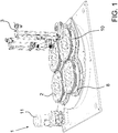
- FIG. 1 illustrates a supply means 1 with its motor 11, platens 2, guides 8, housings 10 and a reel carrier mechanism 3.
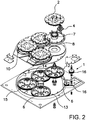
- Figure 2 represents the supply means 1 with intermediate pinion gears 16, first axes 6, platen carrier pinions 12, 13, 14, 15 platens 2, housings 10, guides 8, first pinion 7 and a satellite pinion 4.
- Figure 3 shows the supply means 1, guides 8, first axes 6, platens 2, housings 10, satellite pinions 4 and first pinions 7.
- Figure 4 illustrates platens 2, guides 8, first pinion 7, a second pinion 9, first axis 6 and satellite pinion 4.
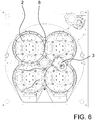
- FIGS. 5 , 6 and 7 illustrate platens 2, reel carrier mechanism 3 and guides 8.
- Figure 8 represents the reel carrier mechanisms 3, platens 2, satellite pinion 4, first pinion 7, second pinions 9 and guide elements 5.
- the machine that is the object of this invention comprises supply means 1 that act by moving platens 2.
- the machine also comprises a guide 8 which, in the embodiment, is a set of four figure-of-eight shaped guides that cross over one another, and even if we were to take an individual guide, it would adopt the shape of an uncrossed eight.
- first axis 6 which belongs to platen 2, which is linked or connected directly or indirectly (as in the embodiment) to supply means 1, so that when the supply means starts to move, they act on the first axis 6, rotating it.
- the first axis 6 ends up on top in a first pinion 7, with which there meshes at least one satellite pinion 4, which is the one that moves along platen 2.
- Satellite pinion 4 is meshed with a second pinion 9 belonging to the reel carrier mechanism 3, which means that the above-mentioned movement of the satellite pinion 4 acts on second pinion 9, moving or shifting reel carrier mechanism 3.
- first axis 6 rotates due to the action of supply means 1, it rotates in turn first pinion 7 which drags satellite pinion 4, moving it.
- reel carrier mechanism 3 will always have the same orientation throughout the trajectory of guide 8, which means that when braiding, the thread does not suffer any kind of tension as a result of rotating reel carrier mechanism 3.
- platen 2 comprises at least one housing 10 (in this embodiment four for each platen 2) wherein reel carrier mechanism 3 is positioned, facilitating the fitting of reel carrier mechanism 3 to platen 2 as it moves along said guide 8.
- first pinion 7, satellite pinion 4 and second pinion 9 are placed under platen 2. This has the advantage that platen 2 protects them, increasing their durability.
- supply means 1 that move platens 2 include a motor 11 which meshes with some platen carrier pinions 12, 13, 14, 15. Said platen carrier pinions 12, 13, 14, 15 are integral with the respective first axes 6, with said first axis 6 rotating in the same rotary direction as the respective platen carrier pinion 12, 13, 14, 15.
- Supply means 1 would be started up, in this embodiment, by a motor 11 which, through some intermediate pinions 16, would transmit movement to one of the platen carrier pinions 12.
- the example has four platen carrier pinions 12, 13, 14, 15, which generate four crossed figure-of-eight guides 8.
- platen carrier pinions 12 The direction of movement that is transmitted to platen carrier pinions 12 is also transmitted to the first axis 6, and in the same way the direction of movement in platen carrier pinions 13, 14, 15 is the same as the respective first pinion 6 in each one.
- first axis 6 ends up on the top in first pinion 7 which rotates in the same direction as first axis 6.
- Said first pinion 7 meshes with satellite pinion 4 which, as you can see in Figure 3 , can be several satellite pinions 4 (four for example) for each first pinion 7.
- said satellite pinion 4 meshes with second pinion 9 belonging to reel carrier mechanism 3, so that when satellite pinion 4 is moving, it drags with its movement reel carrier mechanism 3 which, in turn, follows guide 8 thanks to guide element 5.
- reel carrier mechanism 3 would be located in said housing until platen 2 abandons.
- reel carrier mechanism 3 has completed the trajectory given in one of the platens 2, the actual satellite pinion 4, together with the trajectory of the guide 8 means that reel carrier mechanism 3 moves towards another platen 2, following a figure-of-eight , but without crossing over itself.
- reel carrier mechanism 3 interacts equally with the different elements.
- reel carrier mechanism 3 is orientated always towards the same point, so that thread tensions are avoided, since it always maintains the same orientation.
Landscapes
- Engineering & Computer Science (AREA)
- Textile Engineering (AREA)
- Braiding, Manufacturing Of Bobbin-Net Or Lace, And Manufacturing Of Nets By Knotting (AREA)
- Transmission Devices (AREA)
Abstract
Description
- Braiding machine of the type comprising supply means that move platens on which there are arranged reel carrier mechanisms, characterised in that it comprises: at least one figure-of-eight shaped guide through the inside of which there moves a guide element belonging to the reel carrier mechanism, and a first axis connected to the supply means, belonging to the platen, which ends up at the top in a first pinion with which there meshes at least one satellite pinion which in turn is meshed with a second pinion belonging to the reel carrier mechanism, where when the first axis rotates it rotates in turn the first pinion that drags the satellite pinion moving it, dragging in turn said satellite pinion to the second pinion which moves the reel carrier mechanism along the trajectory of the guide, with the same face of the reel carrier mechanism also ending up facing a predetermined point of reference throughout the whole trajectory by the guide.
- In the state of the art different thread braiding machines are known.
- So, under the state of the art there is Spanish Patent
200102142 - Also Spanish Patent No.
2239359 ES2545491 - Another patent that protects the same concept mentioned above is European Patent No.
EP0483789 (ES2082096 - Finally, along the same line there is Spanish Utility Model No.
0217673 - This application comes under the sector of thread braiding machines.
- The closest document is European Patent No.
2239359 (ES2545491 - Said European patent solves the problem of setting up braiding and tying types by means of an external reel housing and an internal reel housing, connected by a system of deviations.
- The problem is that the moment when braiding the thread, to which we have to add the movement of the reel, means that the thread undergoes significant tension, and that one part of the thread is subject to tension while another part of it is hardly subject to any tension when braiding occurs, and this affects the thread quality and strength.
- The inventor has developed a new invention that means that the thread does not undergo any tension changes, since the reel always keeps the same orientation, so that it is not necessary to compensate the movement of the reel carrier to always keep the same tension in the thread.
- The proposed solution is essentially a mechanical solution, where the reel carrier moves along at least one figure-of-eight shaped circuit, wherein some pinion gears mesh with the reel carrier and maintain said reel carrier always with the appropriate tilt to prevent the thread tension varying as it moves.
- An object of this invention is a braiding machine of the type comprising supply means that move some platens on which there are arranged reel carrier mechanisms characterized in that it comprises at least one figure-of-eight shaped guide through the inside of which there moves a guide element belonging to the reel carrier mechanism and a first axis connected to the supply means, belonging to the platen, and which ends up at the top in a first pinion gear in which there meshes at least one satellite pinion which in turn meshes with a second pinion gear belonging to the reel carrier mechanism, wherein when the first axis rotates it rotates in turn the first pinion that drags the satellite pinion, moving it, dragging said satellite pinion in turn to the second pinion that moves the reel carrier mechanism along the guide trajectory, with the same face of the reel carrier mechanism ending up facing a predetermined point of reference throughout the trajectory by the guide.
- In order to facilitate understanding, seven pages of drawings are attached to this specification, representing a practical embodiment, as a non-limiting example of the scope of this invention:
-
Figure 1 is a perspective elevation view of the object of this invention with two reel carriers in a different platen, -
Figure 2 is an explosion view, but without the reel carriers, -
Figure 3 is a plan view with some transparencies, and -
Figure 4 is a detail showing the arrangement of the different pinion gears, -
Figures 5 to 7 are plan views showing the movement of a thread carrier mechanism along the guide, and -
Figure 8 is a partial, perspective elevation view of the object of this invention with two reel carriers, one in the exploded state. - So
Figure 1 illustrates a supply means 1 with itsmotor 11,platens 2,guides 8,housings 10 and areel carrier mechanism 3. -
Figure 2 represents the supply means 1 withintermediate pinion gears 16,first axes 6,platen carrier pinions platens 2,housings 10,guides 8,first pinion 7 and asatellite pinion 4. -
Figure 3 shows the supply means 1,guides 8,first axes 6,platens 2,housings 10,satellite pinions 4 andfirst pinions 7. -
Figure 4 illustratesplatens 2,guides 8,first pinion 7, asecond pinion 9,first axis 6 andsatellite pinion 4. -
Figures 5 ,6 and7 illustrate platens 2,reel carrier mechanism 3 andguides 8. - Finally,
Figure 8 represents thereel carrier mechanisms 3,platens 2,satellite pinion 4,first pinion 7,second pinions 9 andguide elements 5. - So, in a specific embodiment, the machine that is the object of this invention comprises supply means 1 that act by moving
platens 2. - On said
platens 2reel carrier mechanisms 3 are arranged. - The machine also comprises a
guide 8 which, in the embodiment, is a set of four figure-of-eight shaped guides that cross over one another, and even if we were to take an individual guide, it would adopt the shape of an uncrossed eight. - In the inside of the said
guide 8 there is aguide element 5, belonging to thereel carrier mechanism 3, guiding the movement of thereel carrier mechanism 3 along the mentionedguide 8. - It also includes a
first axis 6 which belongs toplaten 2, which is linked or connected directly or indirectly (as in the embodiment) to supplymeans 1, so that when the supply means starts to move, they act on thefirst axis 6, rotating it. - The
first axis 6 ends up on top in afirst pinion 7, with which there meshes at least onesatellite pinion 4, which is the one that moves alongplaten 2. -
Satellite pinion 4 is meshed with asecond pinion 9 belonging to thereel carrier mechanism 3, which means that the above-mentioned movement of thesatellite pinion 4 acts onsecond pinion 9, moving or shiftingreel carrier mechanism 3. - So, when the
first axis 6 rotates due to the action of supply means 1, it rotates in turnfirst pinion 7 which dragssatellite pinion 4, moving it. - This means that in turn it drags said
satellite pinion 4 tosecond pinion 9 which, as indicated above, since it belongs toreel carrier mechanism 3, the movement on saidsecond pinion 9 implies that it movesreel carrier mechanism 3 as well, asguide element 5 advances along the saidguide 8. - This special configuration means that if we take any reference point outside,
reel carrier mechanism 3 will always have the same orientation throughout the trajectory ofguide 8, which means that when braiding, the thread does not suffer any kind of tension as a result of rotatingreel carrier mechanism 3. - Optionally,
platen 2 comprises at least one housing 10 (in this embodiment four for each platen 2) whereinreel carrier mechanism 3 is positioned, facilitating the fitting ofreel carrier mechanism 3 toplaten 2 as it moves along saidguide 8. - Constructively, it can be envisaged that
first pinion 7,satellite pinion 4 andsecond pinion 9 are placed underplaten 2. This has the advantage thatplaten 2 protects them, increasing their durability. - Also optionally, supply means 1 that move
platens 2 include amotor 11 which meshes with someplaten carrier pinions platen carrier pinions first axes 6, with saidfirst axis 6 rotating in the same rotary direction as the respectiveplaten carrier pinion - So, the machine would operate as follows. Supply means 1 would be started up, in this embodiment, by a
motor 11 which, through someintermediate pinions 16, would transmit movement to one of theplaten carrier pinions 12. - In this embodiment we can see that the example has four
platen carrier pinions guides 8. - So when
platen carrier pinion 12 that receives the movement fromintermediate pinion 16 rotates in one direction, the twoplaten carrier pinions platen carrier pinions 15, will rotate in the same direction as the firstplaten carrier pinion 12. - The direction of movement that is transmitted to
platen carrier pinions 12 is also transmitted to thefirst axis 6, and in the same way the direction of movement inplaten carrier pinions first pinion 6 in each one. - As indicated above
first axis 6 ends up on the top infirst pinion 7 which rotates in the same direction asfirst axis 6. - Said
first pinion 7 meshes withsatellite pinion 4 which, as you can see inFigure 3 , can be several satellite pinions 4 (four for example) for eachfirst pinion 7. - Also, said
satellite pinion 4 meshes withsecond pinion 9 belonging toreel carrier mechanism 3, so that whensatellite pinion 4 is moving, it drags with its movementreel carrier mechanism 3 which, in turn, followsguide 8 thanks to guideelement 5. - If there were the option of
housing 10,reel carrier mechanism 3 would be located in said housing untilplaten 2 abandons. - Once
reel carrier mechanism 3 has completed the trajectory given in one of theplatens 2, theactual satellite pinion 4, together with the trajectory of theguide 8 means thatreel carrier mechanism 3 moves towards anotherplaten 2, following a figure-of-eight , but without crossing over itself. - In the following
platen 2,reel carrier mechanism 3 interacts equally with the different elements. - As can be seen in
Figures 5 to 7 , at all timesreel carrier mechanism 3 is orientated always towards the same point, so that thread tensions are avoided, since it always maintains the same orientation. - If we start with
Figure 5 wherereel carrier mechanism 3 would be in an initial position, when moving and reaching the position inFigure 6 , which is when saidreel carrier mechanism 3 is transferred from oneplaten 2 to another, the orientation that saidreel carrier mechanism 3 has, is the same, so that the thread does not undergo any kind of tension due to the fact thatreel carrier mechanism 3 could pull it in a rotational and translational traction movement. - In
Figure 7 it can be observed that the orientation ofreel carrier mechanism 3 is the same as that inFigures 5 and6 , and this is thanks to the mechanism explained above which would be described forFigures 1 to 4 . - This way, when the thread has been braided in the reel (not shown), the thread has not tensions derived from the rotational movement of
reel carrier mechanism 3 because this does not rotate, or hardly rotates. - This is particularly important when it is a question of producing safety material, where the tensions of braided threads can affect the quality, and therefore the safety of the braided rope.
- This invention describes a new braiding machine. The examples mentioned herein do not limit this invention, therefore it will be able to have different applications and/or adaptations, all within the scope of the following claims.
Claims (4)
- Braiding machine of the type comprising supply means (1) that move some platens (2) on which there are arranged reel carrier mechanisms (3) characterized in that it comprises:- at least one figure-of-eight guide (8) through the inside of which there moves a guide element (5) belonging to reel carrier mechanism (3), and- a first axis (6) connected to supply means (1), belonging to platen (2), which ends up on top in a first pinion (7) with which there meshes at least one satellite pinion (4) which in turn is meshed with a second pinion (9) belonging to reel carrier mechanism (3).wherein when first axis (6) rotates it rotates in turn first pinion (7) that drags satellite pinion (4) moving it, dragging in turn said satellite pinion to second pinion (9) which moves reel carrier mechanism (3) according to the trajectory of guide (8), with the same face of reel carrier mechanism (3) ending up facing a predetermined reference point throughout the trajectory by guide (8).
- Machine, according to claim 1, characterized in that platen (2) comprises at least one housing (10) wherein reel carrier mechanism (3) is positioned.
- Machine, according to claim 1 or 2, characterized in that first pinion (7), satellite pinion (4) and second pinion (9) are placed under platen (2).
- Machine, according to claim 3, characterized in that supply means (1) that move platens (2) comprise a motor (11) that meshes with a platen carrier pinion (12) which, in turn, links with other platen carrier pinions (13, 14, 15) with said platen carrier pinions (12, 13, 14, 15) being integral with the respective first axes (6), with said first axis (6) rotating in the same direction of rotation as the respective platen carrier pinion (12).
Applications Claiming Priority (2)
| Application Number | Priority Date | Filing Date | Title |
|---|---|---|---|
| ES201531634A ES2612143B1 (en) | 2015-11-11 | 2015-11-11 | Braiding machine |
| PCT/ES2016/070135 WO2017081338A1 (en) | 2015-11-11 | 2016-03-01 | Braiding machine |
Publications (2)
| Publication Number | Publication Date |
|---|---|
| EP3375922A1 true EP3375922A1 (en) | 2018-09-19 |
| EP3375922B1 EP3375922B1 (en) | 2021-08-25 |
Family
ID=55661469
Family Applications (1)
| Application Number | Title | Priority Date | Filing Date |
|---|---|---|---|
| EP16714458.3A Active EP3375922B1 (en) | 2015-11-11 | 2016-03-01 | Braiding machine |
Country Status (4)
| Country | Link |
|---|---|
| EP (1) | EP3375922B1 (en) |
| CN (1) | CN108463590B (en) |
| ES (2) | ES2612143B1 (en) |
| WO (1) | WO2017081338A1 (en) |
Cited By (1)
| Publication number | Priority date | Publication date | Assignee | Title |
|---|---|---|---|---|
| US20240125019A1 (en) * | 2020-10-02 | 2024-04-18 | Polyvalor, Limited Partnership | Braiding machines and carriers for braiding machines |
Families Citing this family (2)
| Publication number | Priority date | Publication date | Assignee | Title |
|---|---|---|---|---|
| WO2020249832A1 (en) | 2019-06-14 | 2020-12-17 | Talleres Ratera, S.A. | Braiding machine |
| CN116423889B (en) * | 2023-04-11 | 2023-09-12 | 河北三业流体科技有限责任公司 | Method and device for processing rubber hose braiding layer |
Family Cites Families (8)
| Publication number | Priority date | Publication date | Assignee | Title |
|---|---|---|---|---|
| US3371573A (en) * | 1966-09-26 | 1968-03-05 | Koreki Yoshiaki | Braiding machines |
| ES217673Y (en) | 1975-12-23 | 1977-01-01 | Ratera Portella Eliseo | PERFECTED BRAIDING MACHINE. |
| US5085121A (en) * | 1990-02-09 | 1992-02-04 | Donald Richardson | Braided product and method and apparatus for producing same |
| CS25891A2 (en) * | 1990-02-09 | 1991-09-15 | Donald Richardson | Braided reinforcement of pipe lines especially hoses and method and equipment for its production |
| CA2053471A1 (en) | 1990-10-30 | 1992-05-01 | Ilya Koyfman | Braider apparatus with improved bobbin holder |
| ES2200647B1 (en) | 2001-09-14 | 2005-05-01 | Universitat Politecnica De Catalunya | Constant tension electric uncoiler for braiding machines includes a tension selection printed circuit with sensing, guide and spring loaded contact facilities |
| DE102009017312A1 (en) * | 2009-04-11 | 2010-10-14 | August Herzog Maschinenfabrik Gmbh & Co. Kg | Wound product and method and apparatus for producing the worm product |
| CN202090155U (en) * | 2011-04-28 | 2011-12-28 | 晋江市溢泰织造机械有限公司 | Frame base unit of rope knitting machine |
-
2015
- 2015-11-11 ES ES201531634A patent/ES2612143B1/en active Active
-
2016
- 2016-03-01 ES ES16714458T patent/ES2899208T3/en active Active
- 2016-03-01 WO PCT/ES2016/070135 patent/WO2017081338A1/en not_active Ceased
- 2016-03-01 EP EP16714458.3A patent/EP3375922B1/en active Active
- 2016-03-01 CN CN201680076928.5A patent/CN108463590B/en not_active Expired - Fee Related
Cited By (2)
| Publication number | Priority date | Publication date | Assignee | Title |
|---|---|---|---|---|
| US20240125019A1 (en) * | 2020-10-02 | 2024-04-18 | Polyvalor, Limited Partnership | Braiding machines and carriers for braiding machines |
| US12258690B2 (en) * | 2020-10-02 | 2025-03-25 | Polyvalor, Limited Partnership | Braiding machines and carriers for braiding machines |
Also Published As
| Publication number | Publication date |
|---|---|
| ES2899208T3 (en) | 2022-03-10 |
| EP3375922B1 (en) | 2021-08-25 |
| CN108463590A (en) | 2018-08-28 |
| CN108463590B (en) | 2020-06-26 |
| ES2612143A2 (en) | 2017-05-12 |
| ES2612143R1 (en) | 2017-06-09 |
| WO2017081338A1 (en) | 2017-05-18 |
| ES2612143B1 (en) | 2018-01-17 |
Similar Documents
| Publication | Publication Date | Title |
|---|---|---|
| KR102366639B1 (en) | filament winding device | |
| EP2623297B1 (en) | Filament winding apparatus | |
| EP3375922B1 (en) | Braiding machine | |
| EP2938767B1 (en) | Rotary braiding machine | |
| EP0290380B1 (en) | Weft thread storing apparatus with an automatic thread-measuring device for weaving looms | |
| KR101772994B1 (en) | Device for manufacturing fabric including spandex | |
| US4601774A (en) | Nozzle for coaters and applying filamentary material to a cylindrical core | |
| CA1061145A (en) | Bobbin drive mechanism for a rotary braider | |
| ITFI990118A1 (en) | ELECTRONICALLY CONTROLLED SAMPLES ORDER | |
| DE3017936C2 (en) | Thread wrapping device | |
| WO2021191066A1 (en) | Rotational braiding machine | |
| KR101446440B1 (en) | braiding machine | |
| CN101448724A (en) | Method for producing a winding with separate threads | |
| DE69411226T2 (en) | Yarn delivery system for a high speed knitting machine | |
| DE2454917A1 (en) | METHOD AND DEVICE FOR WINDING CONICAL CROSS SPOOLS AT A CONSTANT THREAD FEED SPEED | |
| CN101173415A (en) | Process for treating threads by knitting-unraveling | |
| KR101406310B1 (en) | A apparatus for manufacturing a twisted yarns | |
| CN101379683A (en) | Winding apparatus | |
| DE2933851C2 (en) | Circular knitting machine | |
| EP1479806A2 (en) | Method for forming a sample warp and sample warper | |
| DE2165045A1 (en) | WINDING PROCESS AND CROSS WINDING MACHINE FOR FAEDEN, FILM TAPES AND THE LIKE | |
| DE19722769A1 (en) | Lap roll winder | |
| DE809456C (en) | Machine for the helical winding of spun fiber material for covers of unvulcanized rubber hose | |
| KR101875108B1 (en) | The winding mechanism of yarn manufactured from the twisting machine | |
| DK156671B (en) | MILLING MACHINE WITH A NUMBER OF HOLES, LINES |
Legal Events
| Date | Code | Title | Description |
|---|---|---|---|
| STAA | Information on the status of an ep patent application or granted ep patent |
Free format text: STATUS: THE INTERNATIONAL PUBLICATION HAS BEEN MADE |
|
| PUAI | Public reference made under article 153(3) epc to a published international application that has entered the european phase |
Free format text: ORIGINAL CODE: 0009012 |
|
| STAA | Information on the status of an ep patent application or granted ep patent |
Free format text: STATUS: REQUEST FOR EXAMINATION WAS MADE |
|
| 17P | Request for examination filed |
Effective date: 20180611 |
|
| AK | Designated contracting states |
Kind code of ref document: A1 Designated state(s): AL AT BE BG CH CY CZ DE DK EE ES FI FR GB GR HR HU IE IS IT LI LT LU LV MC MK MT NL NO PL PT RO RS SE SI SK SM TR |
|
| AX | Request for extension of the european patent |
Extension state: BA ME |
|
| DAV | Request for validation of the european patent (deleted) | ||
| DAX | Request for extension of the european patent (deleted) | ||
| GRAP | Despatch of communication of intention to grant a patent |
Free format text: ORIGINAL CODE: EPIDOSNIGR1 |
|
| STAA | Information on the status of an ep patent application or granted ep patent |
Free format text: STATUS: GRANT OF PATENT IS INTENDED |
|
| INTG | Intention to grant announced |
Effective date: 20210316 |
|
| GRAS | Grant fee paid |
Free format text: ORIGINAL CODE: EPIDOSNIGR3 |
|
| GRAA | (expected) grant |
Free format text: ORIGINAL CODE: 0009210 |
|
| STAA | Information on the status of an ep patent application or granted ep patent |
Free format text: STATUS: THE PATENT HAS BEEN GRANTED |
|
| AK | Designated contracting states |
Kind code of ref document: B1 Designated state(s): AL AT BE BG CH CY CZ DE DK EE ES FI FR GB GR HR HU IE IS IT LI LT LU LV MC MK MT NL NO PL PT RO RS SE SI SK SM TR |
|
| REG | Reference to a national code |
Ref country code: CH Ref legal event code: EP |
|
| REG | Reference to a national code |
Ref country code: IE Ref legal event code: FG4D Ref country code: AT Ref legal event code: REF Ref document number: 1423902 Country of ref document: AT Kind code of ref document: T Effective date: 20210915 |
|
| REG | Reference to a national code |
Ref country code: DE Ref legal event code: R096 Ref document number: 602016062681 Country of ref document: DE |
|
| REG | Reference to a national code |
Ref country code: LT Ref legal event code: MG9D |
|
| REG | Reference to a national code |
Ref country code: NL Ref legal event code: MP Effective date: 20210825 |
|
| REG | Reference to a national code |
Ref country code: AT Ref legal event code: MK05 Ref document number: 1423902 Country of ref document: AT Kind code of ref document: T Effective date: 20210825 |
|
| PG25 | Lapsed in a contracting state [announced via postgrant information from national office to epo] |
Ref country code: SE Free format text: LAPSE BECAUSE OF FAILURE TO SUBMIT A TRANSLATION OF THE DESCRIPTION OR TO PAY THE FEE WITHIN THE PRESCRIBED TIME-LIMIT Effective date: 20210825 Ref country code: RS Free format text: LAPSE BECAUSE OF FAILURE TO SUBMIT A TRANSLATION OF THE DESCRIPTION OR TO PAY THE FEE WITHIN THE PRESCRIBED TIME-LIMIT Effective date: 20210825 Ref country code: BG Free format text: LAPSE BECAUSE OF FAILURE TO SUBMIT A TRANSLATION OF THE DESCRIPTION OR TO PAY THE FEE WITHIN THE PRESCRIBED TIME-LIMIT Effective date: 20211125 Ref country code: AT Free format text: LAPSE BECAUSE OF FAILURE TO SUBMIT A TRANSLATION OF THE DESCRIPTION OR TO PAY THE FEE WITHIN THE PRESCRIBED TIME-LIMIT Effective date: 20210825 Ref country code: LT Free format text: LAPSE BECAUSE OF FAILURE TO SUBMIT A TRANSLATION OF THE DESCRIPTION OR TO PAY THE FEE WITHIN THE PRESCRIBED TIME-LIMIT Effective date: 20210825 Ref country code: HR Free format text: LAPSE BECAUSE OF FAILURE TO SUBMIT A TRANSLATION OF THE DESCRIPTION OR TO PAY THE FEE WITHIN THE PRESCRIBED TIME-LIMIT Effective date: 20210825 Ref country code: FI Free format text: LAPSE BECAUSE OF FAILURE TO SUBMIT A TRANSLATION OF THE DESCRIPTION OR TO PAY THE FEE WITHIN THE PRESCRIBED TIME-LIMIT Effective date: 20210825 Ref country code: PT Free format text: LAPSE BECAUSE OF FAILURE TO SUBMIT A TRANSLATION OF THE DESCRIPTION OR TO PAY THE FEE WITHIN THE PRESCRIBED TIME-LIMIT Effective date: 20211227 Ref country code: NO Free format text: LAPSE BECAUSE OF FAILURE TO SUBMIT A TRANSLATION OF THE DESCRIPTION OR TO PAY THE FEE WITHIN THE PRESCRIBED TIME-LIMIT Effective date: 20211125 |
|
| PG25 | Lapsed in a contracting state [announced via postgrant information from national office to epo] |
Ref country code: PL Free format text: LAPSE BECAUSE OF FAILURE TO SUBMIT A TRANSLATION OF THE DESCRIPTION OR TO PAY THE FEE WITHIN THE PRESCRIBED TIME-LIMIT Effective date: 20210825 Ref country code: LV Free format text: LAPSE BECAUSE OF FAILURE TO SUBMIT A TRANSLATION OF THE DESCRIPTION OR TO PAY THE FEE WITHIN THE PRESCRIBED TIME-LIMIT Effective date: 20210825 Ref country code: GR Free format text: LAPSE BECAUSE OF FAILURE TO SUBMIT A TRANSLATION OF THE DESCRIPTION OR TO PAY THE FEE WITHIN THE PRESCRIBED TIME-LIMIT Effective date: 20211126 |
|
| REG | Reference to a national code |
Ref country code: ES Ref legal event code: FG2A Ref document number: 2899208 Country of ref document: ES Kind code of ref document: T3 Effective date: 20220310 |
|
| PG25 | Lapsed in a contracting state [announced via postgrant information from national office to epo] |
Ref country code: NL Free format text: LAPSE BECAUSE OF FAILURE TO SUBMIT A TRANSLATION OF THE DESCRIPTION OR TO PAY THE FEE WITHIN THE PRESCRIBED TIME-LIMIT Effective date: 20210825 |
|
| PG25 | Lapsed in a contracting state [announced via postgrant information from national office to epo] |
Ref country code: DK Free format text: LAPSE BECAUSE OF FAILURE TO SUBMIT A TRANSLATION OF THE DESCRIPTION OR TO PAY THE FEE WITHIN THE PRESCRIBED TIME-LIMIT Effective date: 20210825 |
|
| REG | Reference to a national code |
Ref country code: DE Ref legal event code: R097 Ref document number: 602016062681 Country of ref document: DE |
|
| PG25 | Lapsed in a contracting state [announced via postgrant information from national office to epo] |
Ref country code: SM Free format text: LAPSE BECAUSE OF FAILURE TO SUBMIT A TRANSLATION OF THE DESCRIPTION OR TO PAY THE FEE WITHIN THE PRESCRIBED TIME-LIMIT Effective date: 20210825 Ref country code: SK Free format text: LAPSE BECAUSE OF FAILURE TO SUBMIT A TRANSLATION OF THE DESCRIPTION OR TO PAY THE FEE WITHIN THE PRESCRIBED TIME-LIMIT Effective date: 20210825 Ref country code: RO Free format text: LAPSE BECAUSE OF FAILURE TO SUBMIT A TRANSLATION OF THE DESCRIPTION OR TO PAY THE FEE WITHIN THE PRESCRIBED TIME-LIMIT Effective date: 20210825 Ref country code: EE Free format text: LAPSE BECAUSE OF FAILURE TO SUBMIT A TRANSLATION OF THE DESCRIPTION OR TO PAY THE FEE WITHIN THE PRESCRIBED TIME-LIMIT Effective date: 20210825 Ref country code: CZ Free format text: LAPSE BECAUSE OF FAILURE TO SUBMIT A TRANSLATION OF THE DESCRIPTION OR TO PAY THE FEE WITHIN THE PRESCRIBED TIME-LIMIT Effective date: 20210825 Ref country code: AL Free format text: LAPSE BECAUSE OF FAILURE TO SUBMIT A TRANSLATION OF THE DESCRIPTION OR TO PAY THE FEE WITHIN THE PRESCRIBED TIME-LIMIT Effective date: 20210825 |
|
| PLBE | No opposition filed within time limit |
Free format text: ORIGINAL CODE: 0009261 |
|
| STAA | Information on the status of an ep patent application or granted ep patent |
Free format text: STATUS: NO OPPOSITION FILED WITHIN TIME LIMIT |
|
| 26N | No opposition filed |
Effective date: 20220527 |
|
| PG25 | Lapsed in a contracting state [announced via postgrant information from national office to epo] |
Ref country code: SI Free format text: LAPSE BECAUSE OF FAILURE TO SUBMIT A TRANSLATION OF THE DESCRIPTION OR TO PAY THE FEE WITHIN THE PRESCRIBED TIME-LIMIT Effective date: 20210825 |
|
| PG25 | Lapsed in a contracting state [announced via postgrant information from national office to epo] |
Ref country code: MC Free format text: LAPSE BECAUSE OF FAILURE TO SUBMIT A TRANSLATION OF THE DESCRIPTION OR TO PAY THE FEE WITHIN THE PRESCRIBED TIME-LIMIT Effective date: 20210825 |
|
| REG | Reference to a national code |
Ref country code: CH Ref legal event code: PL |
|
| REG | Reference to a national code |
Ref country code: BE Ref legal event code: MM Effective date: 20220331 |
|
| PG25 | Lapsed in a contracting state [announced via postgrant information from national office to epo] |
Ref country code: LU Free format text: LAPSE BECAUSE OF NON-PAYMENT OF DUE FEES Effective date: 20220301 Ref country code: LI Free format text: LAPSE BECAUSE OF NON-PAYMENT OF DUE FEES Effective date: 20220331 Ref country code: IE Free format text: LAPSE BECAUSE OF NON-PAYMENT OF DUE FEES Effective date: 20220301 Ref country code: CH Free format text: LAPSE BECAUSE OF NON-PAYMENT OF DUE FEES Effective date: 20220331 |
|
| PG25 | Lapsed in a contracting state [announced via postgrant information from national office to epo] |
Ref country code: BE Free format text: LAPSE BECAUSE OF NON-PAYMENT OF DUE FEES Effective date: 20220331 |
|
| PGFP | Annual fee paid to national office [announced via postgrant information from national office to epo] |
Ref country code: FR Payment date: 20230323 Year of fee payment: 8 |
|
| PGFP | Annual fee paid to national office [announced via postgrant information from national office to epo] |
Ref country code: IT Payment date: 20230324 Year of fee payment: 8 Ref country code: GB Payment date: 20230329 Year of fee payment: 8 |
|
| PG25 | Lapsed in a contracting state [announced via postgrant information from national office to epo] |
Ref country code: HU Free format text: LAPSE BECAUSE OF FAILURE TO SUBMIT A TRANSLATION OF THE DESCRIPTION OR TO PAY THE FEE WITHIN THE PRESCRIBED TIME-LIMIT; INVALID AB INITIO Effective date: 20160301 |
|
| PG25 | Lapsed in a contracting state [announced via postgrant information from national office to epo] |
Ref country code: MK Free format text: LAPSE BECAUSE OF FAILURE TO SUBMIT A TRANSLATION OF THE DESCRIPTION OR TO PAY THE FEE WITHIN THE PRESCRIBED TIME-LIMIT Effective date: 20210825 Ref country code: CY Free format text: LAPSE BECAUSE OF FAILURE TO SUBMIT A TRANSLATION OF THE DESCRIPTION OR TO PAY THE FEE WITHIN THE PRESCRIBED TIME-LIMIT Effective date: 20210825 |
|
| PG25 | Lapsed in a contracting state [announced via postgrant information from national office to epo] |
Ref country code: TR Free format text: LAPSE BECAUSE OF FAILURE TO SUBMIT A TRANSLATION OF THE DESCRIPTION OR TO PAY THE FEE WITHIN THE PRESCRIBED TIME-LIMIT Effective date: 20210825 |
|
| PG25 | Lapsed in a contracting state [announced via postgrant information from national office to epo] |
Ref country code: MT Free format text: LAPSE BECAUSE OF FAILURE TO SUBMIT A TRANSLATION OF THE DESCRIPTION OR TO PAY THE FEE WITHIN THE PRESCRIBED TIME-LIMIT Effective date: 20210825 |
|
| GBPC | Gb: european patent ceased through non-payment of renewal fee |
Effective date: 20240301 |
|
| PG25 | Lapsed in a contracting state [announced via postgrant information from national office to epo] |
Ref country code: GB Free format text: LAPSE BECAUSE OF NON-PAYMENT OF DUE FEES Effective date: 20240301 |
|
| PG25 | Lapsed in a contracting state [announced via postgrant information from national office to epo] |
Ref country code: FR Free format text: LAPSE BECAUSE OF NON-PAYMENT OF DUE FEES Effective date: 20240331 |
|
| PG25 | Lapsed in a contracting state [announced via postgrant information from national office to epo] |
Ref country code: GB Free format text: LAPSE BECAUSE OF NON-PAYMENT OF DUE FEES Effective date: 20240301 Ref country code: FR Free format text: LAPSE BECAUSE OF NON-PAYMENT OF DUE FEES Effective date: 20240331 |
|
| PGFP | Annual fee paid to national office [announced via postgrant information from national office to epo] |
Ref country code: DE Payment date: 20250327 Year of fee payment: 10 |
|
| PG25 | Lapsed in a contracting state [announced via postgrant information from national office to epo] |
Ref country code: IT Free format text: LAPSE BECAUSE OF NON-PAYMENT OF DUE FEES Effective date: 20240301 |
|
| PGFP | Annual fee paid to national office [announced via postgrant information from national office to epo] |
Ref country code: ES Payment date: 20250626 Year of fee payment: 10 |