EP3375392A1 - Bone stabilization systems - Google Patents
Bone stabilization systems Download PDFInfo
- Publication number
- EP3375392A1 EP3375392A1 EP18161322.5A EP18161322A EP3375392A1 EP 3375392 A1 EP3375392 A1 EP 3375392A1 EP 18161322 A EP18161322 A EP 18161322A EP 3375392 A1 EP3375392 A1 EP 3375392A1
- Authority
- EP
- European Patent Office
- Prior art keywords
- holes
- bone
- bone plate
- locking
- rafting
- Prior art date
- Legal status (The legal status is an assumption and is not a legal conclusion. Google has not performed a legal analysis and makes no representation as to the accuracy of the status listed.)
- Granted
Links
Images




Classifications
-
- A—HUMAN NECESSITIES
- A61—MEDICAL OR VETERINARY SCIENCE; HYGIENE
- A61B—DIAGNOSIS; SURGERY; IDENTIFICATION
- A61B17/00—Surgical instruments, devices or methods
- A61B17/56—Surgical instruments or methods for treatment of bones or joints; Devices specially adapted therefor
- A61B17/58—Surgical instruments or methods for treatment of bones or joints; Devices specially adapted therefor for osteosynthesis, e.g. bone plates, screws or setting implements
- A61B17/68—Internal fixation devices, including fasteners and spinal fixators, even if a part thereof projects from the skin
- A61B17/80—Cortical plates, i.e. bone plates; Instruments for holding or positioning cortical plates, or for compressing bones attached to cortical plates
- A61B17/8004—Cortical plates, i.e. bone plates; Instruments for holding or positioning cortical plates, or for compressing bones attached to cortical plates with means for distracting or compressing the bone or bones
- A61B17/8014—Cortical plates, i.e. bone plates; Instruments for holding or positioning cortical plates, or for compressing bones attached to cortical plates with means for distracting or compressing the bone or bones the extension or compression force being caused by interaction of the plate hole and the screws
-
- A—HUMAN NECESSITIES
- A61—MEDICAL OR VETERINARY SCIENCE; HYGIENE
- A61B—DIAGNOSIS; SURGERY; IDENTIFICATION
- A61B17/00—Surgical instruments, devices or methods
- A61B17/16—Instruments for performing osteoclasis; Drills or chisels for bones; Trepans
- A61B17/17—Guides or aligning means for drills, mills, pins or wires
- A61B17/1728—Guides or aligning means for drills, mills, pins or wires for holes for bone plates or plate screws
-
- A—HUMAN NECESSITIES
- A61—MEDICAL OR VETERINARY SCIENCE; HYGIENE
- A61B—DIAGNOSIS; SURGERY; IDENTIFICATION
- A61B17/00—Surgical instruments, devices or methods
- A61B17/56—Surgical instruments or methods for treatment of bones or joints; Devices specially adapted therefor
- A61B17/58—Surgical instruments or methods for treatment of bones or joints; Devices specially adapted therefor for osteosynthesis, e.g. bone plates, screws or setting implements
- A61B17/68—Internal fixation devices, including fasteners and spinal fixators, even if a part thereof projects from the skin
- A61B17/80—Cortical plates, i.e. bone plates; Instruments for holding or positioning cortical plates, or for compressing bones attached to cortical plates
- A61B17/8004—Cortical plates, i.e. bone plates; Instruments for holding or positioning cortical plates, or for compressing bones attached to cortical plates with means for distracting or compressing the bone or bones
-
- A—HUMAN NECESSITIES
- A61—MEDICAL OR VETERINARY SCIENCE; HYGIENE
- A61B—DIAGNOSIS; SURGERY; IDENTIFICATION
- A61B17/00—Surgical instruments, devices or methods
- A61B17/56—Surgical instruments or methods for treatment of bones or joints; Devices specially adapted therefor
- A61B17/58—Surgical instruments or methods for treatment of bones or joints; Devices specially adapted therefor for osteosynthesis, e.g. bone plates, screws or setting implements
- A61B17/68—Internal fixation devices, including fasteners and spinal fixators, even if a part thereof projects from the skin
- A61B17/80—Cortical plates, i.e. bone plates; Instruments for holding or positioning cortical plates, or for compressing bones attached to cortical plates
- A61B17/8033—Cortical plates, i.e. bone plates; Instruments for holding or positioning cortical plates, or for compressing bones attached to cortical plates having indirect contact with screw heads, or having contact with screw heads maintained with the aid of additional components, e.g. nuts, wedges or head covers
-
- A—HUMAN NECESSITIES
- A61—MEDICAL OR VETERINARY SCIENCE; HYGIENE
- A61B—DIAGNOSIS; SURGERY; IDENTIFICATION
- A61B17/00—Surgical instruments, devices or methods
- A61B17/56—Surgical instruments or methods for treatment of bones or joints; Devices specially adapted therefor
- A61B17/58—Surgical instruments or methods for treatment of bones or joints; Devices specially adapted therefor for osteosynthesis, e.g. bone plates, screws or setting implements
- A61B17/68—Internal fixation devices, including fasteners and spinal fixators, even if a part thereof projects from the skin
- A61B17/80—Cortical plates, i.e. bone plates; Instruments for holding or positioning cortical plates, or for compressing bones attached to cortical plates
- A61B17/8052—Cortical plates, i.e. bone plates; Instruments for holding or positioning cortical plates, or for compressing bones attached to cortical plates immobilised relative to screws by interlocking form of the heads and plate holes, e.g. conical or threaded
-
- A—HUMAN NECESSITIES
- A61—MEDICAL OR VETERINARY SCIENCE; HYGIENE
- A61B—DIAGNOSIS; SURGERY; IDENTIFICATION
- A61B17/00—Surgical instruments, devices or methods
- A61B17/56—Surgical instruments or methods for treatment of bones or joints; Devices specially adapted therefor
- A61B17/58—Surgical instruments or methods for treatment of bones or joints; Devices specially adapted therefor for osteosynthesis, e.g. bone plates, screws or setting implements
- A61B17/68—Internal fixation devices, including fasteners and spinal fixators, even if a part thereof projects from the skin
- A61B17/80—Cortical plates, i.e. bone plates; Instruments for holding or positioning cortical plates, or for compressing bones attached to cortical plates
- A61B17/8052—Cortical plates, i.e. bone plates; Instruments for holding or positioning cortical plates, or for compressing bones attached to cortical plates immobilised relative to screws by interlocking form of the heads and plate holes, e.g. conical or threaded
- A61B17/8057—Cortical plates, i.e. bone plates; Instruments for holding or positioning cortical plates, or for compressing bones attached to cortical plates immobilised relative to screws by interlocking form of the heads and plate holes, e.g. conical or threaded the interlocking form comprising a thread
-
- A—HUMAN NECESSITIES
- A61—MEDICAL OR VETERINARY SCIENCE; HYGIENE
- A61B—DIAGNOSIS; SURGERY; IDENTIFICATION
- A61B17/00—Surgical instruments, devices or methods
- A61B17/56—Surgical instruments or methods for treatment of bones or joints; Devices specially adapted therefor
- A61B17/58—Surgical instruments or methods for treatment of bones or joints; Devices specially adapted therefor for osteosynthesis, e.g. bone plates, screws or setting implements
- A61B17/68—Internal fixation devices, including fasteners and spinal fixators, even if a part thereof projects from the skin
- A61B17/80—Cortical plates, i.e. bone plates; Instruments for holding or positioning cortical plates, or for compressing bones attached to cortical plates
- A61B17/8061—Cortical plates, i.e. bone plates; Instruments for holding or positioning cortical plates, or for compressing bones attached to cortical plates specially adapted for particular bones
-
- A—HUMAN NECESSITIES
- A61—MEDICAL OR VETERINARY SCIENCE; HYGIENE
- A61B—DIAGNOSIS; SURGERY; IDENTIFICATION
- A61B17/00—Surgical instruments, devices or methods
- A61B17/56—Surgical instruments or methods for treatment of bones or joints; Devices specially adapted therefor
- A61B17/58—Surgical instruments or methods for treatment of bones or joints; Devices specially adapted therefor for osteosynthesis, e.g. bone plates, screws or setting implements
- A61B17/68—Internal fixation devices, including fasteners and spinal fixators, even if a part thereof projects from the skin
- A61B17/80—Cortical plates, i.e. bone plates; Instruments for holding or positioning cortical plates, or for compressing bones attached to cortical plates
- A61B17/809—Cortical plates, i.e. bone plates; Instruments for holding or positioning cortical plates, or for compressing bones attached to cortical plates with bone-penetrating elements, e.g. blades or prongs
-
- A—HUMAN NECESSITIES
- A61—MEDICAL OR VETERINARY SCIENCE; HYGIENE
- A61B—DIAGNOSIS; SURGERY; IDENTIFICATION
- A61B17/00—Surgical instruments, devices or methods
- A61B17/56—Surgical instruments or methods for treatment of bones or joints; Devices specially adapted therefor
- A61B17/58—Surgical instruments or methods for treatment of bones or joints; Devices specially adapted therefor for osteosynthesis, e.g. bone plates, screws or setting implements
- A61B17/68—Internal fixation devices, including fasteners and spinal fixators, even if a part thereof projects from the skin
- A61B17/74—Devices for the head or neck or trochanter of the femur
-
- A—HUMAN NECESSITIES
- A61—MEDICAL OR VETERINARY SCIENCE; HYGIENE
- A61B—DIAGNOSIS; SURGERY; IDENTIFICATION
- A61B17/00—Surgical instruments, devices or methods
- A61B17/56—Surgical instruments or methods for treatment of bones or joints; Devices specially adapted therefor
- A61B17/58—Surgical instruments or methods for treatment of bones or joints; Devices specially adapted therefor for osteosynthesis, e.g. bone plates, screws or setting implements
- A61B17/68—Internal fixation devices, including fasteners and spinal fixators, even if a part thereof projects from the skin
- A61B17/80—Cortical plates, i.e. bone plates; Instruments for holding or positioning cortical plates, or for compressing bones attached to cortical plates
- A61B17/808—Instruments for holding or positioning bone plates, or for adjusting screw-to-plate locking mechanisms
-
- A—HUMAN NECESSITIES
- A61—MEDICAL OR VETERINARY SCIENCE; HYGIENE
- A61B—DIAGNOSIS; SURGERY; IDENTIFICATION
- A61B17/00—Surgical instruments, devices or methods
- A61B17/56—Surgical instruments or methods for treatment of bones or joints; Devices specially adapted therefor
- A61B17/58—Surgical instruments or methods for treatment of bones or joints; Devices specially adapted therefor for osteosynthesis, e.g. bone plates, screws or setting implements
- A61B17/68—Internal fixation devices, including fasteners and spinal fixators, even if a part thereof projects from the skin
- A61B17/84—Fasteners therefor or fasteners being internal fixation devices
- A61B17/86—Pins or screws or threaded wires; nuts therefor
Definitions
- the present disclosure relates to surgical devices, and more particularly, stabilization systems including plates, for example, for trauma applications.
- Bone fractures can be healed using plating systems. During treatment, one or more screws are placed on either side of a fracture, thereby causing compression and healing of the fracture. There is a need for improved plating systems as well as mechanisms for accurate use of the plating systems.
- a system for treating a fracture in a bone comprises: a bone plate configured to engage the bone, the bone plate comprising a proximal end, a distal end, a head portion, a neck portion and a shaft portion, wherein the head portion comprises a first row of holes and a second row of holes for receiving one or more fasteners therein, wherein the shaft portion comprises at least one additional hole for receiving a fastener therein; at least one fastener received in the head portion and positioned in the first row of holes or second row of holes; and at least one fastener received in the shaft portion and positioned in the at least one additional hole.
- the system comprises: a bone plate configured to engage the bone, the bone plate comprising a proximal end, a distal end, a head portion, a neck portion and a shaft portion, wherein the head portion comprises a first row of holes and a second row of holes for receiving one or more fasteners therein, wherein the shaft portion comprises at least one additional hole for receiving a fastener therein; at least one fastener received in the head portion and positioned in the first row of holes or second row of holes, wherein the at least one fastener is non-threaded; and at least one fastener received in the shaft portion and positioned in the at least one additional hole.
- a system for treating a fracture in a bone comprising: a bone plate configured to engage the bone, the bone plate comprising a proximal end, a distal end, a head portion, a neck portion and a shaft portion, wherein the head portion comprises a first row of holes and a second row of holes for receiving one or more fasteners therein, wherein the shaft portion comprises at least one additional hole for receiving a fastener therein; at least one fastener received in the head portion and positioned in the first row of holes or second row of holes, wherein the at least one fastener is non-threaded; and at least one fastener received in the shaft portion and positioned in the at least one additional hole.
- the system further comprises an aiming guide for assisting in the insertion of one or more fasteners into the bone plate.
- the system further comprises the aiming guide comprises a distal aiming guide capable of attachment to a proximal aiming guide.
- the proximal aiming guide comprises a rotatable dial.
- the head portion comprises at least one multi-functional hole capable of receiving a k-wire or suture therein.
- the at least one multi-functional hole is positioned adjacent to an undercut in the bone plate.
- the first row of holes is comprised of holes that are smaller than holes in the second row of holes.
- the shaft portion comprises a pair of holes for receiving a fastener therein, wherein the pair of holes comprises a stacked hole adjacent a compression slot.
- the shaft portion comprises a scalloped contact surface.
- the at least one fastener received in the shaft portion is threaded.
- Embodiments of the present application are generally directed to devices, systems and methods for bone stabilization.
- embodiments are directed to bone plates that extend across bone members to treat one or more fractures.
- the plates described herein may be adapted to contact one or more of a femur, a distal tibia, a proximal tibia, a proximal humerus, a distal humerus, a clavicle, a fibula, an ulna, a radius, bones of the foot, bones of the hand, or other suitable bone or bones.
- the bone plates may be curved, contoured, straight, or flat.
- the plates may have a head portion that is contoured to match a particular bone surface, such as a metaphysis or diaphysis, flares out from the shaft portion, forms an L-shape, T-shape, Y-shape, etc., with the shaft portion, or that forms any other appropriate shape to fit the anatomy of the bone to be treated.
- the plates may be adapted to secure small or large bone fragments, single or multiple bone fragments, or otherwise secure one or more fractures.
- the systems may include a series of trauma plates and screws designed for the fixation of fractures and fragments in diaphyseal and metaphyseal bone. Different bone plates may be used to treat various types and locations of fractures.
- the bone plates may be comprised of titanium, stainless steel, cobalt chrome, carbon composite, plastic or polymer-such as polyetheretherketone (PEEK), polyethylene, ultra high molecular weight polyethylene (UHMWPE), resorbable polylactic acid (PLA), polyglycolic acid (PGA), combinations or alloys of such materials or any other appropriate material that has sufficient strength to be secured to and hold bone, while also having sufficient biocompatibility to be implanted into a body.
- the bone plates may receive one or more screws or fasteners may be comprised of titanium, cobalt chrome, cobalt-chrome-molybdenum, stainless steel, tungsten carbide, combinations or alloys of such materials or other appropriate biocompatible materials.
- Locking plates include one or more openings for accepting one or more locking fasteners.
- the one or more openings can be partially or fully threaded. In some embodiments, these openings include fully threaded or stacked openings, which accept both locking and non-locking fasteners.
- the locking fasteners include heads that are at least partially threaded.
- the locking fasteners can be monoaxial or polyaxial.
- FIG. 6 of U.S. 15/405,368, filed January 13, 2017 which is hereby incorporated by reference in its entirety.
- Non-locking plates include one or more openings for accepting one or more non-locking fasteners.
- the one or more openings at least in part be non-threaded.
- these openings include non-threaded or stacked openings, which accept both locking and non-locking fasteners.
- the non-locking fasteners include heads that are non-threaded.
- the non-locking fasteners can be monoaxial or polyaxial.
- One non-limiting example of a non-locking fastener (among others) is shown in FIG. 4 of U.S. 15/405,368, filed January 13, 2017 , which is hereby incorporated by reference in its entirety.
- the non-locking fasteners can include dynamic compression screws, which enable dynamic compression of an underlying bone.
- locking plates may be thicker than non-locking plates. Locking plates may be useful for patients that have weaker bone, while non-locking plates may be useful for patients that have strong bone.
- the locking and non-locking plates described below can be attached to different bones to treat fractures.
- the locking and non-locking plates can be used to treat fractures of the tibia, though one skilled in the art will appreciate that the novel plates described herein can be applied to fractures on other types of bone as well.
- the locking and non-locking plates can be considered to be lateral, medial or posteromedial plates.
- the plates can be attached to a lateral, medial or posteromedial aspect of a tibia.
- the plates are not limited to their specific locations on the tibia, and that a surgeon may choose to apply a lateral plate medially or a medial plate laterally, if desired.
- the bone plates shown in FIGS. 1 and 7-10 can be viewed as lateral plates, while the bone plates shown in FIGS. 11-17 can be viewed as medial or posteromedial plates.
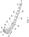
- FIG. 1 is a top perspective view of a bone plate in accordance with some embodiments.
- the bone plate 10 comprises a lateral locking plate, wherein at least some of the fasteners received therein are locking fasteners.
- the bone plate 10 comprises a proximal end 12 and a distal end 14.
- the bone plate 10 further comprises a head portion 22, a shaft portion 26, and a transitionary neck portion 24 between the head portion 22 and the shaft portion 26.
- the head portion 22 comprises a widest portion of the bone plate 10 and is adjacent the proximal end 12.
- the proximal end 12 is chamfered.
- the proximal end 12 contour and chamfer helps to position the bone plate 10 posterior to Gerdy's tubercle to minimize soft tissue irritation in a highly affected area.
- the head portion 22 will be placed on a bone member (e.g., tibia) near an articular surface. Certain features of the head portion 22 are advantageously designed to prevent or resist subsidence of an articular surface.
- the head portion 22 comprises a first row of holes 32 and a second row of holes 34.
- these holes 32, 34 are considered to be "rafting" holes that can receive rafting screws (e.g., as shown in FIG. 30 ) that advantageously support an articular surface of a joint and prevent subsidence.
- the holes 32, 34 are locking holes that are at least partially threaded and designed to receive one or more polyaxial locking screws.
- the head portion 22 comprises a first row of holes 32 and a second row of holes 34, wherein the second row of holes 34 are larger than the first row of holes 32.
- the first row of holes 32 can be between 2.0 and 3.0 mm (e.g., 2.5 mm), while the second row of holes 34 can be between 3.0 and 4.0 mm (e.g., 3.5 mm).
- the bone plate 10 advantageously accommodates a greater number of rafting screws, thereby providing greater support near a joint.
- the most proximal set of holes 32 are especially novel and advantageous, as they are designed to be adjacent the proximal end 12 of the bone plate 10.
- holes 32 receive rafting screws that are closest to an articular surface of a joint. These holes 32 are advantageously smaller in size than holes 34, such that they can accommodate smaller rafting screws, which may be particularly hard to position in the limited space adjacent the articular surface.
- the first row of holes 32 are offset from the second row of holes 34, while in other embodiments, the first row of holes 32 are aligned with the second row of holes 34.
- the first row of holes 32 can have the same number of holes as the second row of holes, while in other embodiments, the first row of holes 32 can have a different number of holes as the second row of holes.
- the bone plate 10 include four holes 32 and four holes 34.
- the head portion 22 further comprises one or more novel multi-purpose holes 36.
- the multi-purpose holes 36 are advantageously designed to accommodate a k-wire as well as a suture.
- the holes 36 are sized and positioned to receive a k-wire therein, thereby assisting in placement of the bone plate 10 on a bone member.
- the holes 36 are formed adjacent and continuously with one or more undercuts 37 (shown in FIGS. 2B and 3 ) of the bone plate 10.
- the one or more undercuts 37 advantageously allow access to one or more sutures through the bone plate 10 even after the bone plate 10 is implanted on bone.
- the sutures can be used to attach the bone plate 10 to adjacent tissue, thereby further securing the bone plate 10 at or near a surgical site.
- the neck portion 24 is a transitionary portion between the head portion 22 and the shaft portion 26.
- the neck portion 24 is less wide than the head portion 22, but has at least some portions that of equal or greater width than the shaft portion 26.
- the neck portion 24 comprises a pair of locking holes 42, an instrument attachment hole 44, alignment indentations 44, a positioning slot, and three kickstand holes 52. Each of these features is described below.
- the pair of locking holes 42 are positioned beneath the rafting holes 32, 34.
- the locking holes 42 comprise polyaxial locking holes that are at least partially threaded.
- the pair of locking holes 42 are configured to receive one or more bone fasteners or screws to secure the bone plate 10 to an underlying bone member.
- the pair of locking holes 42 are the same or similar width to the holes 34.
- each of the locking holes 42 has a width between 3.0 and 4.0 mm (e.g., 3.5 mm).
- the indentations 46 and instrument attachment hole 44 are designed to cooperate with an aiming guide, as shown in FIGS. 18 and 21 .
- the aiming guide is particularly useful with lateral plates, and can be used to accurately guide one or more bone screws or fasteners into respective holes in a bone plate 10.
- the indentations 46 comprise spherical indentations. Unlike other holes or openings in the bone plate 10, the indentations 46 do not extend completely through a plate. Rather, the indentations 46 are engaged by one or more ball-end pins (shown in FIG. 22 ) that extend outwardly from an attachment post of an aiming guide.
- the indentations 46 advantageously help to stabilize and position the aiming guide relative to the bone plate 10. While the bone plate 10 is shown as having three indentations 46, the bone plate 10 can include one, two, or more than three indentations 46. Between the indentations 46 is an instrument attachment hole 44.
- the instrument attachment hole 44 comprises a threaded hole that is designed to receive a threaded shaft (shown in FIG. 22 ) that also extends outwardly from an attachment post of an aiming guide. Once the aiming guide is stabilized via the indentations 46, the aiming guide can be attached to the bone plate 10 via threading of the threaded shaft.
- a positioning slot 48 is located distally and beneath the indentations 46 and instrument attachment hole 44.
- the positioning slot 48 comprises an elongated opening that is designed to receive a first bone screw or fastener therein before finalizing a position of a bone plate 10 on bone.
- the bone plate 10 can be slightly adjusted around a first bone fastener is needed.
- the positioning slot 48 has a length that is greater than a length of any of the other holes that receive bone screws therein.
- the positioning slot 48 has a length that is at least twice the length of a length of any of the other holes that receive bone screws therein.
- the first bone fastener can be provisionally placed in the positioning slot 48 prior to final tightening of the first bone screw. Upon proper orientation and placement of the bone plate 10, the first bone fastener can be finally tightened.
- One or more kickstand holes 62 are provided distally from the positioning slot 48.
- lateral plates may be preferred over medial plates, as they can often be implanted via a smaller incision with less risk to surrounding tissue.
- the one or more kickstand holes 62 are capable of receiving one or more bone fasteners that can treat medial fractures if desired.
- the kickstand holes 62 advantageously allow a medial fracture to be treated via support from just the lateral side.
- the bone plate 10 includes at least three kickstand holes 62.
- the kickstand holes 62 are fixed angle, stacked locking holes.
- the triple kickstand construct serves as a novel collection of kickstand holes 62 aimed at the anterior, middle, and posterior aspects of the medial proximal tibia, thereby providing the surgeon with options and enhanced versatility.
- the triple kickstand construct advantageously provides a surgeon with options for which fragments to target and allows the surgeon to customize construct rigidity with one or more screws or fasteners.
- the kickstand construct will have a single kickstand hole, two kickstand holes, or more than three kickstand holes.
- the shaft portion 26 comprises a distal portion of the bone plate 10 relative to the head portion 22 and neck portion 24. In some embodiments, the shaft portion 26 comprises a longest and narrowest portion of the bone plate 10.
- the shaft portion 26 comprises a number of openings or holes therein for receiving one or more bone fasteners.
- the shaft portion 26 comprises a plurality of holes 62 (e.g., five) that serve as fixed angled, stacked locking holes. These fixed angle, stacked locking holes allow mono-axial insertion of bone fasteners that can be locking or non-locking.
- the shaft portion 26 of the bone plate 10 also comprises a bi-direction, dynamic compression slot 64 that is positioned in between the locking holes 62.
- the bi-directional dynamic compression slot 64 advantageously allows for static insertion of non-locking screws into the shaft of bone. They also allow for compression (e.g., .5 mm - 2 mm) along the shaft of the bone through eccentric insertion of a non-locking screw.
- the holes 62 and slot 64 are capable of receiving one or more screws therein to secure the bone plate 10 to bone.
- the distal portion of the shaft portion 26 further comprises a tapered tip 18.
- the tapered tip 18 serves as an insertion tip that allows the plate 10 to be inserted beneath skin to a surgical site.
- the bone plate 10 can be positioned adjacent to bone (e.g., a tibia), whereby it can be fixed to the bone.
- the tapered tip allows for simplified submuscular plate insertion to minimize incision length.
- an underside of the shaft portion 26 of the bone plate 10 comprises a plurality of scallops 66.
- the scallops 66 form a scalloped contact surface which provides better frictional contact with a bone member.
- the scalloped contact surface minimizes impact to the periosteal blood supply and allows some bending of the shaft portion 26 of the bone plate 10 without deforming threaded holes.
- the bone plate 10 provides an anatomic contour that accommodates a lateral aspect of the proximal tibia.
- the bone plate 10 includes a proximal anterior portion (e.g., chamfered portion) that sits just posterior to Gerdy's tubercle, thereby assisting with positioning while minimizing soft tissue irritation.
- FIG. 2A is a top view of a head of the bone plate of FIG. 1 .
- the head portion 22 comprises a widest most portion of the bone plate 10.
- the head portion 22 accommodates a first row of holes 32a, 32b, 32c, 32d and a second row of holes 34a, 34b, 34c, 34d.
- the first row holes of holes and second row of holes can serve as "rafting" holes to accommodate rafting screws therein.
- the first row of holes 32 are smaller than the second row of holes 34.
- the first row of holes 32 are offset from the second row of holes 34. As shown in FIG.
- a pair of novel multi-purpose holes 36a, 36b are also provided through the head portion 22 of the bone plate 10.
- the multi-purpose holes 36a, 36b are each configured to receive a k-wire and/or suture therethrough.
- FIG. 2B is a bottom view of a head of the bone plate of FIG. 1 . From the bottom view, one can see the underside of the head portion 22 of the bone plate 10. In particular, one can see the underside of the multi-purpose holes 36a, 36b and how they are formed adjacent and continuously with undercuts 37a, 37b formed on the bone plate 10. As shown in FIG. 5 , the undercuts 37a, 37b advantageously allow a suture to be threaded between a bone plate 10 and an underlying bone 2, even when the bone plate 10 is positioned adjacent the bone 2. As shown in FIG. 2B , the undercuts 37a, 37b surround the perimeters of each of the multi-purpose holes 36a, 36b.
- FIG. 3 is a side perspective view of a head of the bone plate of FIG. 1 . From this view, one can see the curved angle of the head portion 22 of the bone plate 10. In addition, one can see how the undercuts 37a, 37b follow the curved contour of the bone plate 10 and are curved themselves.
- FIG. 4 is a view of the bone plate of FIG. 1 attached to a bone.
- the bone plate 10 includes a plurality of screws or fasteners 6 received therein. Screws 6 that are received in the holes 32a, 32b, 32c, 32d, as well as in the holes 34a, 34b, 34c, 34d, can be considered rafting screws.
- the rafting screws are positioned close to an articular surface 4 of the bone 2 (e.g., tibia) and advantageously help to provide support for the articular surface 4. In other words, the rafting screws help to serve as rebar for the articular surface 4. From this view, one can also see a suture undercut 37a that is formed at a corner of the bone plate 10.
- FIG. 5 is an alternative view of the bone plate of FIG. 1 attached to a bone. From this view, one can see how the undercut 37 forms an opening between the bone plate 10 and bone 2 such that there is access to thread a suture even when the bone plate 10 is implanted on bone 2.
- FIG. 6 is a top view of a shaft of the bone plate of FIG. 1 with a cross-sectional view shown beneath.
- the shaft portion 26 includes a number of holes or openings for receiving different bone screws (e.g., locking or non-locking) therein.
- the shaft portion 26 can vary in length to accommodate different bones in different sized patients.
- each of the vertical perforated lines represents a possible cutoff or end of a bone plate 10. For patients with smaller bones, the cut-off could be sooner, while for patients with larger bones, the cut-off could be later.
- the shaft portion 26 accommodates a unique hole or opening pattern whereby the hole immediate preceding a plate end will be a fixed angle, stacked hole 62.
- the bone plate 10 can accommodate either a locking or a non-locking screw, thereby providing a large number of options for a surgeon implanting the plate.
- the novel pattern of holes or openings in the shaft portion 26 includes holes that are spaced apart (e.g., 12-14 mm) center-to-center and allows plate lengths to be offered in two-hole increments while maintaining that the last hole will always be a stacked hole.
- bi-directional compression slots 64 can be worked into the hole pattern, but can appear less than the stacked holes 62 as they may be used less frequently.
- the unique hole pattern maximizes equidistant locking and non-locking options in the shaft portion 26 while still providing dynamic compression capabilities.
- the last hole before the plate end allowing a statically placed locking or non-locking screw is preserved in all two-hole plate increments, as shown in FIG. 6 .
- FIG. 7 is a top perspective view of an alternative bone plate in accordance with some embodiments.
- the bone plate 10 comprises a lateral non-locking plate wherein at least some of holes or openings therein receive non-locking fasteners.
- the bone plate 10 includes similar features to the bone plate in FIG. 1 , including a proximal end 12 and a distal end 14, a head portion 22, a neck portion 24 and a shaft portion 26.
- the head portion 22 accommodates different sized rafting screws via a first row of rafting holes 32 and a second row of rafting holes 34.
- the head portion 22 also includes multi-purpose holes 34 capable of receiving a k-wire and/or suture therein.
- the bone plate 10 can include additional non-locking holes for receiving non-locking fasteners, as will be discussed in greater detail herein.
- the neck portion 24 can comprise holes 42 beneath the rafting holes.
- the holes 42 comprise a trio of non-locking holes capable of receiving non-locking fasteners therein. Beneath the holes 42 comprises an elongated positioning slot 48 for receiving a first bone screw, as discussed above.
- the shaft portion 26 comprises a number of non-locking holes.
- Shaft portion 26 comprises a non-locking hole 62 for receiving a non-locking fastener.
- shaft portion 26 comprises a series of bi-directional dynamic compression slots 64 (which can also be viewed as non-locking openings) for receiving one or more bone fasteners therein.
- the distal end 14 of the bone plate 10 comprises a tapered tip 18 that aids in insertion of the bone plate 10.
- An underside of the shaft portion 26 comprises a plurality of scallops 66.
- FIG. 8 is a top perspective view of an alternative bone plate in accordance with some embodiments.
- the bone plate 10 comprises a lateral plate 10 having one or more locking holes for receiving locking fasteners.
- the thickness of the lateral bone plate 10 varies from 2.2 mm proximally to 3.4 mm distally, with the thickness transition occurring in the neck of the bone plate 10.
- the bone plate 10 includes many features as the bone plate in FIG. 1 , including a proximal end 12, a distal end 14, a head portion 22, a neck portion 24, and a shaft portion 26.
- the head portion 22 is the widest portion of the bone plate 10 and includes a pair of rows of rafting holes 32, 34, as well as a pair of multi-functional holes 36 for receiving a k-wire and/or suture therein.
- the neck portion 24 is also similar to that of the bone plate in FIG. 1 , as it includes a pair of polyaxial locking holes 42, a trio of spherical alignment indentations 46, a threaded instrument attachment hole 44, a positioning slot 48 and a trio of kickstand holes 52.
- the shaft portion 26 of the bone plate 10 of FIG. 8 comprises a different pattern of holes as will be discussed herein.
- the shaft portion 26 comprises a plurality of holes 62, 64.
- the holes 62 comprise fixed angle locking holes (e.g., 3.5 mm), while the adjacent holes 64 comprise dynamic compression slots.
- the shaft portion 26 comprises several pairs of fixed angle locking holes 62 adjacent the dynamic compression slots 64, which can be viewed as non-locking.
- FIG. 9 is a top perspective view of an alternative bone plate in accordance with some embodiments.
- the bone plate 10 comprises a lateral plate 10 having one or more locking holes for receiving locking fasteners.
- the bone plate 10 includes many features as the bone plate in FIG. 1 , including a proximal end 12, a distal end 14, a head portion 22, a neck portion 24, and a shaft portion 26.
- the head portion 22 is the widest portion of the bone plate 10 and includes a pair of rows of rafting holes 32, 34.
- the head portion 22 includes a k-wire recess therein 22 that is separate from a pair of suture holes 74.
- the neck portion 24 is also similar to that of the bone plate in FIG. 1 , as it includes a pair of polyaxial locking holes 42, a trio of spherical alignment indentations 46, a threaded instrument attachment hole 44, a positioning slot 48 and a trio of kickstand holes 52.
- the shaft portion 26 of the bone plate 10 of FIG. 9 comprises a different pattern of holes as will be discussed herein.
- the shaft portion 26 comprises a plurality of fixed angle, locking holes 62. Unlike the prior embodiments, there is no compression slot or hole positioned adjacent the locking holes 62. In some embodiments, the fixed angle, locking holes are spaced evenly, while in other embodiments, the fixed angle, locking holes are not spaced evenly. In addition to these locking holes 62, the shaft portion 26 further comprises a tapered tip 18 and a scalloped contact surface.
- FIG. 10 is a top perspective view of an alternative bone plate in accordance with some embodiments.
- the bone plate 110 comprises a medial plate which can be placed on a bone (e.g., tibia) via a medial approach.
- the thickness of the medial bone plate 110 varies from 2.2 mm proximally to 3.4 mm distally, with the thickness transition occurring in the neck of the bone plate 110.
- the bone plate 110 comprises a proximal end 112 and a distal end 114.
- a head portion 122, neck portion 124 and shaft portion 126 extend between the proximal end 112 and distal end 114.
- the head portion 122 comprises a widest most portion of the bone plate 110, and includes a series of holes 134 for receiving fasteners therein.
- the holes 134 comprise polyaxial locking holes configured to receive one or more locking fasteners therein.
- the head portion 122 comprises four locking holes 134.
- the head portion 122 can comprise one, two, three or more than four locking holes 134.
- the holes are between 2.5 mm and 4.5 mm, such as approximately 3.5 mm.
- the head portion 122 further comprises one or more k-wire openings 136.
- the k-wire openings 136 are positioned near the proximal end 112 of the plate 110 and are configured to receive one or more k-wires therethrough.
- the head portion 122 can be sized and configured to extend to an anterior portion of a bone (e.g, a tibia).
- the neck portion 124 comprises a pair of holes 142 for receiving one or more fasteners therein.
- the holes 142 comprise polyaxial locking holes that are between 2.5 mm and 4.5 mm (e.g., 3.5 mm).
- the locking holes are threaded so as to receive one or more threaded locking fasteners.
- a positioning slot 148 is positioned between the locking holes 142.
- the positioning slot 148 is an elongated slot (e.g., greater than two times the length of the adjacent holes 142) that is configured to receive a first screw therein.
- the shaft portion 126 comprises a plurality of holes 162, as well as a compression slot 164.
- the plurality of holes 162 comprise fixed angle, stacked locking holes that are between 2.5 mm and 4.5 mm, such as 3.5 mm.
- the compression slot 1645 comprises a bi-directional dynamic compression slot.
- the shaft portion 126 further comprises a tapered tip 118 that assists the bone plate 110 during insertion.
- the shaft portion 126 comprises an underside having one or more scallops 166 forming a scalloped contacting surface.
- FIG. 11 is a top perspective view of an alternative bone plate in accordance with some embodiments.
- the bone plate 110 comprises a medial plate.
- the bone plate 110 is similar to the bone plate in FIG. 10 , and includes a proximal end 112, a distal end 114, a head portion 122, a neck portion 124 and a shaft portion 126.
- the shape and size of the head portion 122 is distinguishable.
- the head portion 122 is offset from a longitudinal axis of the bone plate.
- the offset head allows the bone plate 110 to reach a posterior portion of a bone member (e.g., tibia).
- a bone member e.g., tibia
- FIG. 12 is a top perspective view of an alternative bone plate in accordance with some embodiments.
- the bone plate 110 comprises a posteromedial plate that can be inserted through an incision over a posteromedial aspect of a bone (e.g,. tibia).
- the bone plate 110 includes a number of similar features as the medial plates in FIGS. 10 and 11 , including a proximal end 112, a distal end 114, a head portion 122, a neck portion 124, and a shaft portion 126.
- the bone plate 110 includes several non-locking holes 134 in the head portion 122, as well as several stacked locking holes 162 in the shaft portion 126.
- the head portion 122 comprises a row of non-locking holes 134 (e.g., between 2.5 mm and 4.5 mm) that are positioned below a row of k-wire holes.
- the head portion 122 comprises a single non-locking hole 142 positioned below the row of non-locking holes 134.
- the shaft portion 126 comprises a series of fixed angle, stacked locking holes 162 (e.g., between 2.5 mm and 4.5 mm) including a bi-directinal dynamic compression slot 164 therebetween.
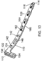
- FIG. 13 is a top perspective view of an alternative bone plate in accordance with some embodiments.
- the bone plate 110 comprises a medial plate that is inserted through an incision over a medial aspect of a bone (e.g., tibia).
- the bone plate 110 is similar to the bone plate in FIG. 11 , but includes a different hole pattern along the shaft portion 126.
- the shaft portion 126 comprises several pairs of holes - a fixed angled locking hole 162 (between 2.5 mm and 4.5 mm) adjacent a dynamic compression slot 164.
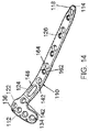
- FIG. 14 is a top perspective view of an alternative bone plate in accordance with some embodiments.
- the bone plate 110 comprises a medial plate that is inserted through an incision over a medial aspect of a bone (e.g., tibia).
- the bone plate 110 is similar to the bone plate in FIG. 13 , except the head portion 122 of the bone plate 110 includes a plurality of non-locking holes 134, 142 (between 2.5 mm and 4.5 mm) rather than locking holes.
- FIG. 15 is a top perspective view of an alternative bone plate in accordance with some embodiments.
- the bone plate 110 comprises a medial plate that is inserted through an incision over a medial aspect of a bone (e.g., tibia).
- the bone plate 110 includes a proximal end 112, a distal end 114, a head portion 122, a neck portion 124 and a shaft portion 126.
- the head portion comprises a row of polyaxial locking holes 134 (between 2.5 mm and 4.5 mm).
- the locking holes 134 are formed distally beneath suture holes 174.
- the suture holes 174 are independent from a recess 172 for a k-wire.
- the head portion 122 also includes a fixed angle locking hole 142 (between 2.5 mm and 4.5 mm).
- the neck portion 124 comprises a positioning slot 148 and an additional fixed angle locking hole 142.
- the shaft portion 126 comprises a plurality of alternating locked or unlocked holes 162 and compression slots 164.
- FIG. 16 is a top perspective view of an alternative bone plate in accordance with some embodiments.
- the bone plate 110 comprises a posteromedial plate that is inserted through an incision over a posteromedial aspect of a bone (e.g., tibia).
- the bone plate 110 includes similar features as prior embodiments, including a head portion 122 having polyaxial locking holes 134 (between 2.5 mm - 4.5 mm), suture holes 174 and a k-wire recess 172.
- the neck portion 124 includes a pair of fixed angle locking holes 142 (between 2.5 mm and 4.5 mm) and a positioning slot 148 therebetween.
- the shaft portion 126 comprises a series of in-line openings or holes 162 that can accommodate a locking or non-locking fastener therein.
- an aiming guide can be provided to assist a surgeon in placing one or more screws or fasteners into a patient.
- the aiming guide can be mounted to a bone plate, and can include guide holes that align with holes in the bone plate such that screws or fasteners can be accurately implanted into a patient.
- the guide holes can accept aiming sleeves that interface with drill guides, trocars, k-wires and screws. These sleeves can be secured to the aiming guide by a ratcheting or clipping mechanism. While the aiming guide can be particularly useful for lateral plates, the aiming guide can also be used for medial and posteromedial plates.
- FIG. 17 is a top perspective view of an aiming guide in accordance with some embodiments.
- the aiming guide 200 can be mounted to an underlying plate 10, and includes an aiming arm 210 and an aiming mount 230.
- the aiming arm 210 comprises a plurality of guide holes 262a, 262b, 262c, 262d that correspond with holes 62a, 62b, 62c, 62d of the plate 10.
- the purpose of the guide holes 262 is to help guide one or more fasteners or screws into the corresponding holes 62 with precision and accuracy.
- the guide holes 262 can receive aiming sleeves that interface with drill guides, trocars, k-wires or screws.
- the aiming arm 210 includes an opening 264 on one end for receiving an arm fixation bolt 236 therein and an opening 266 on the opposing end for receiving a distal locking bolt 238 therein.
- the arm fixation bolt 236 is configured to extend and secure the aiming arm 210 to the aiming mount 230.
- the distal locking bolt 238 is configured to engage an opening near a distal end of a bone plate 10, thereby providing a stable construct.
- the aiming arm 210 is formed of a non-metal, such as a carbon fiber. By forming the aiming arm 210 of a non-metal, this advantageously prevents it from being visible on an x-ray.
- the aiming mount 230 which is attached to the aiming arm 210, serves as a mount on the plate 10.
- the aiming mount 230 (shown in FIGS. 18 and 19 ) comprises an upright post portion including a pair of openings 244 for receiving an anti-rotation bolt 234 therein and an opening 244 for receiving a fixation bolt 232 therein.
- the fixation bolt 232 serves to attach the aiming mount 230 (and thus the entire aiming guide 200) to a plate 10.
- the fixation bolt 232 can be received in an attachment hole 44 (shown in FIG. 1 ) of the plate 10.
- the anti-rotation bolt 234 can be inserted into either of the mono-axial openings 244 to provide additional rigidity during insertion.
- the aiming mount 230 can be a different material from aiming arm 210, as the aiming mount 230 does not obstruct viewing of the holes 62 in the plate 10.
- the aiming mount 230 can be formed of metal while the aiming arm 210 can be formed of non-metal. The means of connecting the aiming arm 210 to the aiming mount 230 will not be described in more detail.
- FIG. 18 is a side view of a mount of the aiming guide of FIG. 17 .
- the aiming mount 230 comprises an upright post having an upper section and a lower section.
- the upper section comprises a plurality of openings 235 (shown in FIG. 19 ) for receiving stabilizing pins 240 therein.
- the aiming arm 210 attaches to the aiming mount 230 by sliding over the stabilizing pins 240 and tightening the arm fixation bolt 236.
- the arm fixation bolt 236 is received in a threaded mounting hole 237 (shown in FIG. 19 ) that is formed on the upper section of the aiming mount 230.
- the aiming mount 230 further comprises a lower section including openings 244 for receiving one or more anti-rotation bolts 234 (shown in FIG. 17 ).
- the one or more anti-rotation bolts 234 provide additional rigidity to the aiming mount 230.
- the lower section includes another opening 231 through which the fixation bolt 232 (shown in FIG. 17 ) extends therethrough.
- the lower section can further include a positioning feature 239 that guides and orients the aiming mount 230 into a proper position relative to the underlying bone plate 10.
- FIG. 19 is an alternative side view of a mount of the aiming guide of FIG. 17 . From this view, one can see specific features of the upper section and lower section of the aiming mount 230. In particular, in the upper section, one can see the plurality of openings 235 for receiving stabilizing pins 240 therein. In addition, one can see the threaded mounting hole 237 that receives the arm fixation bolt 236 to secure the aiming arm 210 to the aiming mount 230. Between the upper section and the lower section of the aiming mount 230 is an opening 231 for receiving the fixation bolt 232 therein. From this view, one can see the openings 244 in the lower section for receiving one or more anti-rotation bolts 234 therein.
- FIG. 20 is a top perspective view of an aiming guide comprising a distal aiming guide and an optional proximal aiming guide in accordance with some embodiments.
- the distal aiming guide 210 is capable of guiding one or more fasteners or screws into distal openings or holes (such as holes or slots 62, 64) of the bone plate 10
- the proximal aiming guide 310 is capable of guiding one or more fasteners or screws into proximal openings or holes (such as rafting holes 32, 34) of the bone plate 10.
- both the distal and proximal aiming guides 210, 310 are capable of accepting one or more aiming sleeves that interface with drill guides, trocars, k-wires, and screws. These sleeves can be secured to the respective guide by a ratcheting or clipping mechanism.
- the distal aiming guide 210 comprises an arm including a plurality of guide holes 262 formed therein.
- the plurality of guide holes 262 are sized and configured to receive one or more aiming sleeves 270 that interface with drill guides, trocars, k-wires and screws.
- the one or more aiming sleeves 270 help guide screws into holes or slots 62, 64.
- the arm includes an extension portion 263 that includes one or more additional guide holes 265 for receiving one or more aiming sleeves 270 therein.
- the one or more sleeves 270 received in the one or more guide holes 265 can be used to direct screws or fasteners into one or kickstand holes of the bone plate 10.
- the distal aiming guide 210 further comprises at least one opening for receiving an attachment post 280 therethrough.
- the attachment post 280 is configured to attach to the bone plate 10.
- the proximal aiming guide 310 comprises one or more guide holes 362 that can be used to direct screws or fasteners into the rafting holes 32, 34 of the bone plate 10.
- each of the guide holes 362 is formed of a pair of overlapping openings or circles.
- guide hole 362a is formed of a pair of overlapping openings or circles, as are guide holes 362b, 362c, 362d.
- guide hole 362a will guide a screw into rafting hole 32a
- guide hole 362b will guide a screw into rafting hole 32b
- guide hole 362c will guide a screw into rafting hole 32c
- guide hole 362d will guide a screw into rafting hole 32d.
- the dial 360 of the proximal aiming guide 310 can assume four different positions at 20 degrees apart for targeting holes in the underlying plate 10 that are coaxial with the holes 362 in the guide.
- the proximal aiming guide 310 can rotate out of the way to allow for easier visualization of the plate 10.
- the proximal aiming guide 310 comprises a dial 360 that indicates which of the guide holes 362a, 362b, 362c, 362d will be available for use. In some embodiments, only a single guide hole 362a, 362b, 362c, 362d will be available in each setting, thereby reducing the risk of confusion to a surgeon.
- the dial is rotatable and has a setting that corresponds with each of the guide holes 362, 362b, 362c, 362d.
- FIG. 21 is a top perspective view of the distal aiming guide of FIG. 20 .
- the distal aiming guide 210 comprises an arm having a plurality of guide holes 262 extending along a length of the arm.
- the guide holes 262 correspond to one or more holes or slots in the bone plate 10, thereby allowing a screw to be easily guided into a proper position on the plate.
- the guide holes 262 are coaxial with holes or slots in the bone plate 10.
- the guide holes 262 accept a guide (e.g., a sleeve) in different positions to target non-locking plate holes in either a static or eccentric position. This facilitates percutaneous insertion of non-locking screws either statically or for dynamic compression.
- the distal aiming guide 210 includes guide holes 262 that correspond with holes or slots in the shaft portion 26 of the bone plate 10, as well as guide holes 265 that correspond with kickstand holes in the neck portion 24.
- the guide holes 262 that correspond with holes or slots in the shaft portion 26 accepts only one type of aiming sleeve 270, while the guides holes 265 that correspond with the kickstand holes in the neck portion 26 accept another type of aiming sleeve 270.
- the distal aiming guide 210 can be formed of a radiolucent material to prevent obstruction of fluoroscopic imaging while in an operating room.
- the distal aiming guide 210 includes a pair of attachment arms 267, 269.
- the first attachment arm 267 comprises a first connection 281a and the second connection arm 269 comprises a second connection 281b.
- Each of these connections 281a, 281b is capable of attachment to an optional proximal aiming guide 310.
- the distal aiming guide 210 is advantageously reversible such that it is can be acceptably used via left hand or right hand.
- FIG. 22 is a bottom perspective view of an attachment post in accordance with some embodiments.
- the attachment post 280 is insertable through a connection opening 381 in the proximal aiming guide 310 (shown in FIG. 20 ), as well as through a connection 281 (shown in FIG. 21 ) in the distal aiming guide 210 (shown in FIG. 21 ).
- the attachment post 280 is configured to engage an underlying bone plate 10.
- the attachment post 280 comprises one or more ball-end pins 282 for engaging alignment indentations 44 (shown in FIG. 1 ) of the bone plate 10.
- the attachment post 280 comprises a threaded shaft 284 for threadingly attaching to an instrument attachment hole 44 in the bone plate 10.
- the attachment post 280 further comprises a stabilizing feature 287 that assists with alignment during attachment.
- FIG. 23 is a top perspective view of the proximal aiming guide of FIG. 20 . From this view, one can see the guide holes 362a, 362b, 362c, 362d, as well as the dial 360 that determines which of the guide holes 362a, 362b, 362c, 362d is available for use. In addition, FIG. 23 shows neighboring guide holes 392 through which one or more additional aiming sleeves can be inserted. In addition, a connection opening 381 is shown through which an attachment post 280 can be received therein.
- connection opening 381 in the proximal aiming guide 310 is coaxial with a connection 281 in the distal aiming guide 210, such that the attachment post 280 can extend through both the proximal aiming guide 310 and the distal aiming guide 210.
- FIG. 24 is a top perspective view of the distal aiming guide with proximal aiming guide of FIG. 20 . From this view, one can see how the attachment post 280 extends through the connection opening 381 of the proximal aiming guide 310 and into the connection 281 in the distal aiming guide 210 before engaging the bone plate 10.
- the attachment post 280 advantageously serves as a means to secure the distal aiming guide 210 with the proximal aiming guide 310.
- FIG. 25A is a view of the distal aiming guide with proximal aiming guide in a first setting.
- the aiming sleeve 270 is capable of being inserted into guide hole 362a.
- FIG. 25B is a view of the distal aiming guide with proximal aiming guide in a second setting.
- the aiming sleeve 270 is capable of being inserted into guide hole 362b.
- FIG. 25C is a view of the distal aiming guide with proximal aiming guide in a third setting.
- the aiming sleeve 270 is capable of being inserted into guide hole 362c.
- FIG. 25D is a view of the distal aiming guide with proximal aiming guide in a fourth setting.
- the aiming sleeve 270 is capable of being inserted into guide hole 362d.
- FIG. 26 is a cross-sectional view of a dial in the proximal aiming guide.
- FIG. 27 is a top perspective view of dial in the proximal aiming guide.
- the dial 360 comprises a rotating mechanism that uses a variation of a Hirth coupling 382 and a spring 384 that accommodates different settings. As the dial 360 is rotated by hand, the top coupling 382a of the Hirth coupling 382 exerts a force on the bottom coupling 382b causing it to translate axially along a shaft. Once clearance is achieved, the dial 360 will complete its designed rotation (e.g., 20 degrees) with a click.
- the retention cap 387 holds the dial 360 in place axially along the shaft and counteracts the force of the spring 384 which forces the bottom coupling 382b to translate down with the rotation.
- embodiments of the bone plates can include one or more rows of rafting openings or holes for receiving rafting screws therein.
- These rafting screws can be provided at or near an articular joint of a bone, thereby reducing the risk of subsidence at the articular joint. More details regarding the rafting screws, as well the optional use of non-threaded rafting blades, are provided below.
- FIG. 28 is a front view of a bone plate including rafting screws attached to a bone member.
- the bone plate 10 can be any of the bone plates described above and can include fasteners or screws 6 extending therethrough. As shown in the figure, the upper row of screws 6 can be considered rafting screws. These rafting screws not only help to treat a bone fracture, but they have to prevent subsidence near the articular joint.
- FIG. 29 is a side view of the bone plate of FIG. 28 . From this view, one can see the rafting screws extending across a fracture in the bone. The rafting screws are positioned adjacent to the articular joint to prevent subsidence near the articular joint.
- FIG. 30 is a top view of the bone plate of FIG. 28 . From this view, one can see how the rafting screws serve as rebar and provide support for the articular joint.
- non-threading rafting blades can be provided.
- these non-threaded blades help to (i) provide better support of an articular surface, (ii) minimize time in surgery due to ease of insertion; and (iii) have a reduced risk of post-operative back out.
- FIG. 31 is a top perspective view of a rafting blade in accordance with some embodiments.
- the rafting blade 406 can be used in addition to, or as an alternative to, the threaded rafting screws described previously.
- one or more rafting blades 406 can be inserted through a bone plate that has been secured to bone via one or more fasteners or screws. The one or more blades can then be locked to the bone plate to prevent post-operative back out.
- the rafting blade 406 comprises a proximal end 412 and a distal cutting end 414.
- the distal cutting end 414 advantageously enables the rafting blade 406 to be inserted into bone with ease, simply by impacting the proximal end 412 of the rafting blade 406.
- the rafting blade 406 is curved or arced.
- the rafting blade 406 is concave, thereby forming a concave rafting surface.
- the rafting blade 406 comprises a structural rib 422 that extends along a longitudinal axis of the rafting blade 406. The structural rib 422 and concave rafting surface advantageously improve the bending moment along the length of the rafting blade 406, thereby providing support against failure during and after insertion.
- FIG. 32 is a top view of the rafting blade of FIG. 31 . From this view, one can see how the structural rib 406 extends along a central longitudinal axis of the rafting blade 406. In some embodiments, the structural rib 406 extends along a majority of the length of the central longitudinal axis of the rafting blade 406.
- FIG. 33 is a side view of the rafting blade of FIG. 31 . From this view, one can see the concave curvature of the rafting blade 406.
- FIG. 34 is a side view of a pair of rafting blades attached to a plate in accordance with some embodiments.
- the plate 10 comprises a curved or domed plate contact surface that facilitates rotation in one plane allowing the rafting blades 406 to be inserted parallel to an articular surface regardless of plate position.
- rafting blades 406 can be inserted at a similar angle to one another. In other embodiments, rafting blades 406 can be inserted at different angles from one another.
- FIG. 35A is a front view of the rafting blade of FIG. 31 . From this view, one can see how the rafting blade 406 comprises a k-wire hole 430.
- the rafting blade 406 can be cannulated to allow guided insertion by k-wire. In some embodiments, the rafting blade 406 can be tapped into bone via use of a slotted hammer.
- FIG. 35B is a bottom perspective view of the rafting blade of FIG. 31 . From this view, one can see the underside of the rafting blade 406 and its cannulated k-wire hole 430.
- FIG. 36 is a top perspective view of an insertion guide for rafting blades in accordance with some embodiments.
- FIG. 37 is a top view of the insertion guide detached from the rafting blades of FIG. 36 .
- the insertion guide 500 allows for a set of parallel or variable angled rafting blades 406 to be inserted simultaneously into a bone member. In other embodiments, a rafting blade can be individually installed. By accommodating a set of rafting blades, the insertion guide 500 advantageously reduces the time in surgery.
- the insertion guide 500 comprises a block that can temporarily engage or attach to a bone plate after the bone plate has been secured to bone.
- the block can include a series of channels or openings through which the rafting blades 406 can be inserted therein.
- a plurality of rafting blades 406 are preloaded into the insertion guide 500.
- the insertion guide 500 can be used without preloading rafting blades 406, thereby allowing a surgeon to select lengths that best suit a particular patient.
- the rafting blades 406 can be tapped into bone in sequence.
- three rafting blades 406 can be inserted in the insertion guide 500.
- the middle blade can be shaped in such a way to prevent back out of the other two rafting blades, as shown in FIG. 38 .
- FIG. 38 is a top view of the rafting blades following insertion in accordance with some embodiments.
- Three rafting blades 406 are provided in the insertion guide 500.
- the blades 406 include first blade 406a, second blade 406b, and third blade 406c.
- the blades 406 are tapped in a particular sequence such that the third blade 406c prevents backout of the first and second blades 406a, 406b.
- the third blade 406c can be sized and configured (e.g., via its proximal head portion) to prevent inadvertent backout of the first blade 406a and the second blade 406b.
- FIG. 39 is a top perspective view of rafting blades and an independent support screw in accordance with some embodiments.
- rafting blades 406 that are inserted into a bone plate 10 through rafting holes 432 are accompanied by a support screw 506.
- the support screw 506 advantageously supports the tips of the rafting blades 406 after insertion.
- FIG. 40A is a front view of a blocking mechanism for the rafting blades in accordance with some embodiments.
- FIG. 40B is a front view of the blocking mechanism of FIG. 40A rotated.
- the blocking mechanism 520 comprises a blocking screw.
- the blocking mechanism 520 comprises a rotating member that allows insertion of rafting blades 406 in one configuration, but prevents the rafting blades 406 from backing out in another rotated configuration.
- the blocking mechanism 520 can simply be installed behind the middle rafting blade 406.
- FIG. 41 is a side view of a rafting blade and locking cap in accordance with some embodiments.
- the locking cap advantageously prevents the rafting blade from toggling within a bone plate and keeps it within the bone plate.
- a locking cap 440 can be used to collapse over a spherical head 410 of a rafting blade 406.
- the outside of the locking cap 440 can have a conical surface with cutouts 442 around its diameter.
- the cutouts 442 are zigzagged or z-shaped.
- the cutouts 442 are slits.
- the inside of the locking cap 440 can be spherical to allow the variable angle installation of a rafting blade 406.
- the locking cap 440 can be threaded. As the locking cap 440 is threaded into a bone plate, its conical geometry and cutouts 442 allow it to collapse over the spherical head 410, grip to the grooved surface of the spherical head 410 and lock it into plate within a bone plate.
- FIG. 42 is a top perspective view of the rafting blade attached to the locking cap of FIG. 41 . From this view, one can see how the head of the rafting blade 406 is received in the locking cap 440.
- FIG. 43 is a top perspective view of the locking cap of FIG. 41 . From this view, one can see the inner portion of the threaded locking cap 440. In addition, one can see how the cutouts 442 are formed around a perimeter of the locking cap 440. As shown in FIG. 43 , cutouts 442 can be initiated at a top or bottom section of the locking cap 440.
- FIG. 44 is a top perspective view of a rafting blade having deforming ridges in accordance with some embodiments.
- FIG. 45 is a bottom perspective view of the rafting blade having deforming ridges of FIG. 44 .
- the rafting blade 406 can comprises one or more ridges 450 where it contacts a bone plate. These one or more ridges 450 can cause a small amount of deformation in the bone plate as the bone plate is inserted, which would advantageously help to lock the rafting blade 406 in place.
- the rafting blade 406 can comprise a pair of ridges 450, each of which is off-center from a longitudinal axis of the rafting blade 406.
- bone plates may be described as suitable for a particular approach (e.g., medial or lateral), one skilled in the art will appreciate that the bone plates can be used for multiple approaches.
- bone plates are described as having particular holes (e.g., locking or non-locking), one skilled in the art will appreciate that any of the bone plates can include locking, non-locking or a combination of locking and non-locking holes.
- screws and instruments described above, one skilled in the art will appreciate that these described features can be used with a number of trauma treatment instruments and implants, including external fixators, ring fixators, rods, and other plates and screws.
- the invention could be defined inter alia by the following aspects:
Landscapes
- Health & Medical Sciences (AREA)
- Orthopedic Medicine & Surgery (AREA)
- Surgery (AREA)
- Life Sciences & Earth Sciences (AREA)
- Heart & Thoracic Surgery (AREA)
- Veterinary Medicine (AREA)
- Engineering & Computer Science (AREA)
- Biomedical Technology (AREA)
- Nuclear Medicine, Radiotherapy & Molecular Imaging (AREA)
- Medical Informatics (AREA)
- Molecular Biology (AREA)
- Animal Behavior & Ethology (AREA)
- General Health & Medical Sciences (AREA)
- Public Health (AREA)
- Neurology (AREA)
- Dentistry (AREA)
- Oral & Maxillofacial Surgery (AREA)
- Surgical Instruments (AREA)
Abstract
Description
- This application is a non-provisional application that claims priority to
U.S. Provisional Application 62/470,470, filed March 13, 2017 - The present disclosure relates to surgical devices, and more particularly, stabilization systems including plates, for example, for trauma applications.
- Bone fractures can be healed using plating systems. During treatment, one or more screws are placed on either side of a fracture, thereby causing compression and healing of the fracture. There is a need for improved plating systems as well as mechanisms for accurate use of the plating systems.
- In accordance with the application, a system for treating a fracture in a bone is provided. In some embodiments, the system comprises: a bone plate configured to engage the bone, the bone plate comprising a proximal end, a distal end, a head portion, a neck portion and a shaft portion, wherein the head portion comprises a first row of holes and a second row of holes for receiving one or more fasteners therein, wherein the shaft portion comprises at least one additional hole for receiving a fastener therein; at least one fastener received in the head portion and positioned in the first row of holes or second row of holes; and at least one fastener received in the shaft portion and positioned in the at least one additional hole.
- In other embodiments, the system comprises: a bone plate configured to engage the bone, the bone plate comprising a proximal end, a distal end, a head portion, a neck portion and a shaft portion, wherein the head portion comprises a first row of holes and a second row of holes for receiving one or more fasteners therein, wherein the shaft portion comprises at least one additional hole for receiving a fastener therein; at least one fastener received in the head portion and positioned in the first row of holes or second row of holes, wherein the at least one fastener is non-threaded; and at least one fastener received in the shaft portion and positioned in the at least one additional hole.
According to a further aspect of the invention it is provided a system for treating a fracture in a bone comprising: a bone plate configured to engage the bone, the bone plate comprising a proximal end, a distal end, a head portion, a neck portion and a shaft portion, wherein the head portion comprises a first row of holes and a second row of holes for receiving one or more fasteners therein, wherein the shaft portion comprises at least one additional hole for receiving a fastener therein; at least one fastener received in the head portion and positioned in the first row of holes or second row of holes, wherein the at least one fastener is non-threaded; and at least one fastener received in the shaft portion and positioned in the at least one additional hole.
In a version, the system further comprises an aiming guide for assisting in the insertion of one or more fasteners into the bone plate.
In a version, the system further comprises the aiming guide comprises a distal aiming guide capable of attachment to a proximal aiming guide.
In a version the proximal aiming guide comprises a rotatable dial.
In a further version the head portion comprises at least one multi-functional hole capable of receiving a k-wire or suture therein.
In another version, the at least one multi-functional hole is positioned adjacent to an undercut in the bone plate.
In still another version the first row of holes is comprised of holes that are smaller than holes in the second row of holes.
In a further version the shaft portion comprises a pair of holes for receiving a fastener therein, wherein the pair of holes comprises a stacked hole adjacent a compression slot.
In another version the shaft portion comprises a scalloped contact surface.
In a further version the at least one fastener received in the shaft portion is threaded. - A more complete understanding of the present invention, and the attendant advantages and features thereof, will be more readily understood by reference to the following detailed description when considered in conjunction with the accompanying drawings, wherein:
-
FIG. 1 is a top perspective view of a bone plate in accordance with some embodiments. -
FIG. 2A is a top view of a head of the bone plate ofFIG. 1 . -
FIG. 2B is a bottom view of a head of the bone plate ofFIG. 1 . -
FIG. 3 is a side perspective view of a head of the bone plate ofFIG. 1 . -
FIG. 4 is a view of the bone plate ofFIG. 1 attached to a bone. -
FIG. 5 is an alternative view of the bone plate ofFIG. 1 attached to a bone. -
FIG. 6 is a top view of a shaft of the bone plate ofFIG. 1 with a cross-sectional view shown beneath. -
FIG. 7 is a top perspective view of an alternative bone plate in accordance with some embodiments. -
FIG. 8 is a top perspective view of an alternative bone plate in accordance with some embodiments. -
FIG. 9 is a top perspective view of an alternative bone plate in accordance with some embodiments. -
FIG. 10 is a top perspective view of an alternative bone plate in accordance with some embodiments. -
FIG. 11 is a top perspective view of an alternative bone plate in accordance with some embodiments. -
FIG. 12 is a top perspective view of an alternative bone plate in accordance with some embodiments. -
FIG. 13 is a top perspective view of an alternative bone plate in accordance with some embodiments. -
FIG. 14 is a top perspective view of an alternative bone plate in accordance with some embodiments. -
FIG. 15 is a top perspective view of an alternative bone plate in accordance with some embodiments. -
FIG. 16 is a top perspective view of an alternative bone plate in accordance with some embodiments. -
FIG. 17 is a top perspective view of an aiming guide in accordance with some embodiments. -
FIG. 18 is a side view of a mount of the aiming guide ofFIG. 17 . -
FIG. 19 is an alternative side view of a mount of the aiming guide ofFIG. 17 . -
FIG. 20 is a top perspective view of an aiming guide comprising a distal aiming guide and an optional proximal aiming guide in accordance with some embodiments. -
FIG. 21 is a top perspective view of the aiming guide ofFIG. 20 . -
FIG. 22 is a bottom perspective view of an attachment post in accordance with some embodiments. -
FIG. 23 is a top perspective view of the proximal aiming guide ofFIG. 20 . -
FIG. 24 is a top perspective view of the distal aiming guide with optional proximal aiming guide ofFIG. 20 . -
FIG. 25A is a view of the distal aiming guide with proximal aiming guide in a first setting. -
FIG. 25B is a view of the distal aiming guide with proximal aiming guide in a second setting. -
FIG. 25C is a view of the distal aiming guide with proximal aiming guide in a third setting. -
FIG. 25D is a view of the distal aiming guide with proximal aiming guide in a fourth setting. -
FIG. 26 is a cross-sectional view of a dial in the proximal aiming guide. -
FIG. 27 is a top perspective view of dial in the proximal aiming guide. -
FIG. 28 is a front view of a bone plate including rafting screws attached to a bone member. -
FIG. 29 is a side view of the bone plate ofFIG. 28 . -
FIG. 30 is a top view of the bone plate ofFIG. 28 . -
FIG. 31 is a top perspective view of a rafting blade in accordance with some embodiments. -
FIG. 32 is a top view of the rafting blade ofFIG. 31 . -
FIG. 33 is a side view of the rafting blade ofFIG. 31 . -
FIG. 34 is a side view of a pair of rafting blades attached to a plate in accordance with some embodiments. -
FIG. 35A is a front view of the rafting blade ofFIG. 31 . -
FIG. 35B is a bottom perspective view of the rafting blade ofFIG. 31 . -
FIG. 36 is a top perspective view of an insertion guide for rafting blades in accordance with some embodiments. -
FIG. 37 is a top view of the insertion guide detached from the rafting blades ofFIG. 36 . -
FIG. 38 is a top view of the rafting blades following insertion in accordance with some embodiments. -
FIG. 39 is a top perspective view of rafting blades and an independent support screw in accordance with some embodiments. -
FIG. 40A is a front view of a blocking mechanism for the rafting blades in accordance with some embodiments. -
FIG. 40B is a front view of the blocking mechanism ofFIG. 40A rotated. -
FIG. 41 is a side view of a rafting blade and locking cap in accordance with some embodiments. -
FIG. 42 is a top perspective view of the rafting blade attached to the locking cap ofFIG. 41 . -
FIG. 43 is a top perspective view of the locking cap ofFIG. 41 . -
FIG. 44 is a top perspective view of a rafting blade having deforming ridges in accordance with some embodiments. -
FIG. 45 is a bottom perspective view of the rafting blade having deforming ridges ofFIG. 44 . - Embodiments of the present application are generally directed to devices, systems and methods for bone stabilization. In particular, embodiments are directed to bone plates that extend across bone members to treat one or more fractures.
- The plates described herein may be adapted to contact one or more of a femur, a distal tibia, a proximal tibia, a proximal humerus, a distal humerus, a clavicle, a fibula, an ulna, a radius, bones of the foot, bones of the hand, or other suitable bone or bones. The bone plates may be curved, contoured, straight, or flat. The plates may have a head portion that is contoured to match a particular bone surface, such as a metaphysis or diaphysis, flares out from the shaft portion, forms an L-shape, T-shape, Y-shape, etc., with the shaft portion, or that forms any other appropriate shape to fit the anatomy of the bone to be treated. The plates may be adapted to secure small or large bone fragments, single or multiple bone fragments, or otherwise secure one or more fractures. In particular, the systems may include a series of trauma plates and screws designed for the fixation of fractures and fragments in diaphyseal and metaphyseal bone. Different bone plates may be used to treat various types and locations of fractures.
- The bone plates may be comprised of titanium, stainless steel, cobalt chrome, carbon composite, plastic or polymer-such as polyetheretherketone (PEEK), polyethylene, ultra high molecular weight polyethylene (UHMWPE), resorbable polylactic acid (PLA), polyglycolic acid (PGA), combinations or alloys of such materials or any other appropriate material that has sufficient strength to be secured to and hold bone, while also having sufficient biocompatibility to be implanted into a body. Similarly, the bone plates may receive one or more screws or fasteners may be comprised of titanium, cobalt chrome, cobalt-chrome-molybdenum, stainless steel, tungsten carbide, combinations or alloys of such materials or other appropriate biocompatible materials. Although the above list of materials includes many typical materials out of which bone plates and fasteners are made, it should be understood that bone plates and fasteners comprised of any appropriate material are contemplated.
- The bone plates described herein can be considered "locking" or "non-locking" plates. Locking plates include one or more openings for accepting one or more locking fasteners. The one or more openings can be partially or fully threaded. In some embodiments, these openings include fully threaded or stacked openings, which accept both locking and non-locking fasteners. In some embodiments, the locking fasteners include heads that are at least partially threaded. The locking fasteners can be monoaxial or polyaxial. One non-limiting example of a locking fastener (among others) is shown in
FIG. 6 ofU.S. 15/405,368, filed January 13, 2017 - Non-locking plates include one or more openings for accepting one or more non-locking fasteners. The one or more openings at least in part be non-threaded. In some embodiments, these openings include non-threaded or stacked openings, which accept both locking and non-locking fasteners. In some embodiments, the non-locking fasteners include heads that are non-threaded. The non-locking fasteners can be monoaxial or polyaxial. One non-limiting example of a non-locking fastener (among others) is shown in
FIG. 4 ofU.S. 15/405,368, filed January 13, 2017 - Below are various examples of locking and non-locking plates attachable to bone. In some embodiments, locking plates may be thicker than non-locking plates. Locking plates may be useful for patients that have weaker bone, while non-locking plates may be useful for patients that have strong bone.
- The locking and non-locking plates described below can be attached to different bones to treat fractures. In particular, the locking and non-locking plates can be used to treat fractures of the tibia, though one skilled in the art will appreciate that the novel plates described herein can be applied to fractures on other types of bone as well. With respect to the tibia, the locking and non-locking plates can be considered to be lateral, medial or posteromedial plates. In other words, the plates can be attached to a lateral, medial or posteromedial aspect of a tibia. One skilled in the art will appreciate, however, that the plates are not limited to their specific locations on the tibia, and that a surgeon may choose to apply a lateral plate medially or a medial plate laterally, if desired. In the present application, the bone plates shown in
FIGS. 1 and7-10 can be viewed as lateral plates, while the bone plates shown inFIGS. 11-17 can be viewed as medial or posteromedial plates. -
FIG. 1 is a top perspective view of a bone plate in accordance with some embodiments. In some embodiments, thebone plate 10 comprises a lateral locking plate, wherein at least some of the fasteners received therein are locking fasteners. Thebone plate 10 comprises aproximal end 12 and adistal end 14. Thebone plate 10 further comprises ahead portion 22, ashaft portion 26, and atransitionary neck portion 24 between thehead portion 22 and theshaft portion 26. - The
head portion 22 comprises a widest portion of thebone plate 10 and is adjacent theproximal end 12. In some embodiments, theproximal end 12 is chamfered. Advantageously, theproximal end 12 contour and chamfer helps to position thebone plate 10 posterior to Gerdy's tubercle to minimize soft tissue irritation in a highly affected area. In some embodiments, thehead portion 22 will be placed on a bone member (e.g., tibia) near an articular surface. Certain features of thehead portion 22 are advantageously designed to prevent or resist subsidence of an articular surface. Thehead portion 22 comprises a first row ofholes 32 and a second row ofholes 34. In some embodiments, theseholes FIG. 30 ) that advantageously support an articular surface of a joint and prevent subsidence. In some embodiments, theholes - As shown in
FIG. 1 , thehead portion 22 comprises a first row ofholes 32 and a second row ofholes 34, wherein the second row ofholes 34 are larger than the first row ofholes 32. For example, in some embodiments, the first row ofholes 32 can be between 2.0 and 3.0 mm (e.g., 2.5 mm), while the second row ofholes 34 can be between 3.0 and 4.0 mm (e.g., 3.5 mm). By providing two sets ofholes bone plate 10 advantageously accommodates a greater number of rafting screws, thereby providing greater support near a joint. In particular, the most proximal set ofholes 32 are especially novel and advantageous, as they are designed to be adjacent theproximal end 12 of thebone plate 10. Theseholes 32 receive rafting screws that are closest to an articular surface of a joint. Theseholes 32 are advantageously smaller in size thanholes 34, such that they can accommodate smaller rafting screws, which may be particularly hard to position in the limited space adjacent the articular surface. In some embodiments, the first row ofholes 32 are offset from the second row ofholes 34, while in other embodiments, the first row ofholes 32 are aligned with the second row ofholes 34. In some embodiments, the first row ofholes 32 can have the same number of holes as the second row of holes, while in other embodiments, the first row ofholes 32 can have a different number of holes as the second row of holes. In the present embodiment, thebone plate 10 include fourholes 32 and fourholes 34. - As shown in
FIG. 1 , thehead portion 22 further comprises one or more novelmulti-purpose holes 36. In some embodiments, themulti-purpose holes 36 are advantageously designed to accommodate a k-wire as well as a suture. In some embodiments, theholes 36 are sized and positioned to receive a k-wire therein, thereby assisting in placement of thebone plate 10 on a bone member. Theholes 36 are formed adjacent and continuously with one or more undercuts 37 (shown inFIGS. 2B and3 ) of thebone plate 10. As shown inFIG. 5 , the one ormore undercuts 37 advantageously allow access to one or more sutures through thebone plate 10 even after thebone plate 10 is implanted on bone. The sutures can be used to attach thebone plate 10 to adjacent tissue, thereby further securing thebone plate 10 at or near a surgical site. - The
neck portion 24 is a transitionary portion between thehead portion 22 and theshaft portion 26. Theneck portion 24 is less wide than thehead portion 22, but has at least some portions that of equal or greater width than theshaft portion 26. As shown inFIG. 1 , theneck portion 24 comprises a pair of lockingholes 42, aninstrument attachment hole 44,alignment indentations 44, a positioning slot, and three kickstand holes 52. Each of these features is described below. - The pair of locking
holes 42 are positioned beneath the rafting holes 32, 34. In some embodiments, the locking holes 42 comprise polyaxial locking holes that are at least partially threaded. The pair of lockingholes 42 are configured to receive one or more bone fasteners or screws to secure thebone plate 10 to an underlying bone member. In some embodiments, the pair of lockingholes 42 are the same or similar width to theholes 34. In some embodiments, each of the locking holes 42 has a width between 3.0 and 4.0 mm (e.g., 3.5 mm). - Below the pair of locking
holes 42 areindentations 46 and aninstrument attachment hole 44. Theindentations 46 andinstrument attachment hole 44 are designed to cooperate with an aiming guide, as shown inFIGS. 18 and21 . The aiming guide is particularly useful with lateral plates, and can be used to accurately guide one or more bone screws or fasteners into respective holes in abone plate 10. In some embodiments, theindentations 46 comprise spherical indentations. Unlike other holes or openings in thebone plate 10, theindentations 46 do not extend completely through a plate. Rather, theindentations 46 are engaged by one or more ball-end pins (shown inFIG. 22 ) that extend outwardly from an attachment post of an aiming guide. Theindentations 46 advantageously help to stabilize and position the aiming guide relative to thebone plate 10. While thebone plate 10 is shown as having threeindentations 46, thebone plate 10 can include one, two, or more than threeindentations 46. Between theindentations 46 is aninstrument attachment hole 44. Theinstrument attachment hole 44 comprises a threaded hole that is designed to receive a threaded shaft (shown inFIG. 22 ) that also extends outwardly from an attachment post of an aiming guide. Once the aiming guide is stabilized via theindentations 46, the aiming guide can be attached to thebone plate 10 via threading of the threaded shaft. - A
positioning slot 48 is located distally and beneath theindentations 46 andinstrument attachment hole 44. Thepositioning slot 48 comprises an elongated opening that is designed to receive a first bone screw or fastener therein before finalizing a position of abone plate 10 on bone. As thepositioning slot 48 is elongated, thebone plate 10 can be slightly adjusted around a first bone fastener is needed. In some embodiments, thepositioning slot 48 has a length that is greater than a length of any of the other holes that receive bone screws therein. In some embodiments, thepositioning slot 48 has a length that is at least twice the length of a length of any of the other holes that receive bone screws therein. The first bone fastener can be provisionally placed in thepositioning slot 48 prior to final tightening of the first bone screw. Upon proper orientation and placement of thebone plate 10, the first bone fastener can be finally tightened. - One or more kickstand holes 62 are provided distally from the
positioning slot 48. In some instances, lateral plates may be preferred over medial plates, as they can often be implanted via a smaller incision with less risk to surrounding tissue. The one or more kickstand holes 62 are capable of receiving one or more bone fasteners that can treat medial fractures if desired. In other words, the kickstand holes 62 advantageously allow a medial fracture to be treated via support from just the lateral side. As shown inFIG. 1 , thebone plate 10 includes at least three kickstand holes 62. In some embodiments, the kickstand holes 62 are fixed angle, stacked locking holes. By providing a triple kickstand construct with threekickstand holes 62, this advantageously accommodates up to three bone fasteners to better support a medial fracture. In some embodiments, the triple kickstand construct serves as a novel collection of kickstand holes 62 aimed at the anterior, middle, and posterior aspects of the medial proximal tibia, thereby providing the surgeon with options and enhanced versatility. The triple kickstand construct advantageously provides a surgeon with options for which fragments to target and allows the surgeon to customize construct rigidity with one or more screws or fasteners. In other embodiments, the kickstand construct will have a single kickstand hole, two kickstand holes, or more than three kickstand holes. - The
shaft portion 26 comprises a distal portion of thebone plate 10 relative to thehead portion 22 andneck portion 24. In some embodiments, theshaft portion 26 comprises a longest and narrowest portion of thebone plate 10. Theshaft portion 26 comprises a number of openings or holes therein for receiving one or more bone fasteners. In the present embodiment, theshaft portion 26 comprises a plurality of holes 62 (e.g., five) that serve as fixed angled, stacked locking holes. These fixed angle, stacked locking holes allow mono-axial insertion of bone fasteners that can be locking or non-locking. In addition, as shown inFIG. 1 , theshaft portion 26 of thebone plate 10 also comprises a bi-direction,dynamic compression slot 64 that is positioned in between the locking holes 62. The bi-directionaldynamic compression slot 64 advantageously allows for static insertion of non-locking screws into the shaft of bone. They also allow for compression (e.g., .5 mm - 2 mm) along the shaft of the bone through eccentric insertion of a non-locking screw. Theholes 62 andslot 64 are capable of receiving one or more screws therein to secure thebone plate 10 to bone. - The distal portion of the
shaft portion 26 further comprises a taperedtip 18. In some embodiments, the taperedtip 18 serves as an insertion tip that allows theplate 10 to be inserted beneath skin to a surgical site. Thebone plate 10 can be positioned adjacent to bone (e.g., a tibia), whereby it can be fixed to the bone. In some embodiments, the tapered tip allows for simplified submuscular plate insertion to minimize incision length. As shown inFIG. 1 , an underside of theshaft portion 26 of thebone plate 10 comprises a plurality ofscallops 66. Thescallops 66 form a scalloped contact surface which provides better frictional contact with a bone member. In some embodiments, the scalloped contact surface minimizes impact to the periosteal blood supply and allows some bending of theshaft portion 26 of thebone plate 10 without deforming threaded holes. - In some embodiments, the
bone plate 10 provides an anatomic contour that accommodates a lateral aspect of the proximal tibia. In some embodiments, thebone plate 10 includes a proximal anterior portion (e.g., chamfered portion) that sits just posterior to Gerdy's tubercle, thereby assisting with positioning while minimizing soft tissue irritation. -
FIG. 2A is a top view of a head of the bone plate ofFIG. 1 . Thehead portion 22 comprises a widest most portion of thebone plate 10. As shown inFIG. 2A , thehead portion 22 accommodates a first row ofholes holes holes 32 are smaller than the second row ofholes 34. In addition, in some embodiments, the first row ofholes 32 are offset from the second row ofholes 34. As shown inFIG. 2A , a pair of novelmulti-purpose holes head portion 22 of thebone plate 10. Themulti-purpose holes FIG. 2A are features of theneck portion 24, including the lockingholes indentations instrument attachment hole 44. -
FIG. 2B is a bottom view of a head of the bone plate ofFIG. 1 . From the bottom view, one can see the underside of thehead portion 22 of thebone plate 10. In particular, one can see the underside of themulti-purpose holes undercuts bone plate 10. As shown inFIG. 5 , theundercuts bone plate 10 and anunderlying bone 2, even when thebone plate 10 is positioned adjacent thebone 2. As shown inFIG. 2B , theundercuts multi-purpose holes -
FIG. 3 is a side perspective view of a head of the bone plate ofFIG. 1 . From this view, one can see the curved angle of thehead portion 22 of thebone plate 10. In addition, one can see how theundercuts bone plate 10 and are curved themselves. -
FIG. 4 is a view of the bone plate ofFIG. 1 attached to a bone. Thebone plate 10 includes a plurality of screws orfasteners 6 received therein.Screws 6 that are received in theholes holes FIG. 4 , the rafting screws are positioned close to anarticular surface 4 of the bone 2 (e.g., tibia) and advantageously help to provide support for thearticular surface 4. In other words, the rafting screws help to serve as rebar for thearticular surface 4. From this view, one can also see a suture undercut 37a that is formed at a corner of thebone plate 10. -
FIG. 5 is an alternative view of the bone plate ofFIG. 1 attached to a bone. From this view, one can see how the undercut 37 forms an opening between thebone plate 10 andbone 2 such that there is access to thread a suture even when thebone plate 10 is implanted onbone 2. -
FIG. 6 is a top view of a shaft of the bone plate ofFIG. 1 with a cross-sectional view shown beneath. Theshaft portion 26 includes a number of holes or openings for receiving different bone screws (e.g., locking or non-locking) therein. In some embodiments, theshaft portion 26 can vary in length to accommodate different bones in different sized patients. As shown inFIG. 6 , each of the vertical perforated lines represents a possible cutoff or end of abone plate 10. For patients with smaller bones, the cut-off could be sooner, while for patients with larger bones, the cut-off could be later. In some embodiments, theshaft portion 26 accommodates a unique hole or opening pattern whereby the hole immediate preceding a plate end will be a fixed angle,stacked hole 62. By providing astacked hole 62 that precedes a plate end, thebone plate 10 can accommodate either a locking or a non-locking screw, thereby providing a large number of options for a surgeon implanting the plate. In some embodiments, the novel pattern of holes or openings in theshaft portion 26 includes holes that are spaced apart (e.g., 12-14 mm) center-to-center and allows plate lengths to be offered in two-hole increments while maintaining that the last hole will always be a stacked hole. In some embodiments,bi-directional compression slots 64 can be worked into the hole pattern, but can appear less than the stackedholes 62 as they may be used less frequently. The unique hole pattern maximizes equidistant locking and non-locking options in theshaft portion 26 while still providing dynamic compression capabilities. In addition, the last hole before the plate end allowing a statically placed locking or non-locking screw is preserved in all two-hole plate increments, as shown inFIG. 6 . -
FIG. 7 is a top perspective view of an alternative bone plate in accordance with some embodiments. In some embodiments, thebone plate 10 comprises a lateral non-locking plate wherein at least some of holes or openings therein receive non-locking fasteners. Thebone plate 10 includes similar features to the bone plate inFIG. 1 , including aproximal end 12 and adistal end 14, ahead portion 22, aneck portion 24 and ashaft portion 26. Thehead portion 22 accommodates different sized rafting screws via a first row of rafting holes 32 and a second row of rafting holes 34. Thehead portion 22 also includesmulti-purpose holes 34 capable of receiving a k-wire and/or suture therein. However, thebone plate 10 can include additional non-locking holes for receiving non-locking fasteners, as will be discussed in greater detail herein. - In some embodiments, the
neck portion 24 can compriseholes 42 beneath the rafting holes. Theholes 42 comprise a trio of non-locking holes capable of receiving non-locking fasteners therein. Beneath theholes 42 comprises anelongated positioning slot 48 for receiving a first bone screw, as discussed above. - In some embodiments, the
shaft portion 26 comprises a number of non-locking holes.Shaft portion 26 comprises anon-locking hole 62 for receiving a non-locking fastener. In addition,shaft portion 26 comprises a series of bi-directional dynamic compression slots 64 (which can also be viewed as non-locking openings) for receiving one or more bone fasteners therein. Thedistal end 14 of thebone plate 10 comprises a taperedtip 18 that aids in insertion of thebone plate 10. An underside of theshaft portion 26 comprises a plurality ofscallops 66. -
FIG. 8 is a top perspective view of an alternative bone plate in accordance with some embodiments. In some embodiments, thebone plate 10 comprises alateral plate 10 having one or more locking holes for receiving locking fasteners. In some embodiments, the thickness of thelateral bone plate 10 varies from 2.2 mm proximally to 3.4 mm distally, with the thickness transition occurring in the neck of thebone plate 10. Thebone plate 10 includes many features as the bone plate inFIG. 1 , including aproximal end 12, adistal end 14, ahead portion 22, aneck portion 24, and ashaft portion 26. Thehead portion 22 is the widest portion of thebone plate 10 and includes a pair of rows of rafting holes 32, 34, as well as a pair ofmulti-functional holes 36 for receiving a k-wire and/or suture therein. Theneck portion 24 is also similar to that of the bone plate inFIG. 1 , as it includes a pair of polyaxial locking holes 42, a trio ofspherical alignment indentations 46, a threadedinstrument attachment hole 44, apositioning slot 48 and a trio of kickstand holes 52. However, theshaft portion 26 of thebone plate 10 ofFIG. 8 comprises a different pattern of holes as will be discussed herein. - As shown in
FIG. 8 , theshaft portion 26 comprises a plurality ofholes holes 62 comprise fixed angle locking holes (e.g., 3.5 mm), while theadjacent holes 64 comprise dynamic compression slots. Theshaft portion 26 comprises several pairs of fixedangle locking holes 62 adjacent thedynamic compression slots 64, which can be viewed as non-locking. -
FIG. 9 is a top perspective view of an alternative bone plate in accordance with some embodiments. In some embodiments, thebone plate 10 comprises alateral plate 10 having one or more locking holes for receiving locking fasteners. Thebone plate 10 includes many features as the bone plate inFIG. 1 , including aproximal end 12, adistal end 14, ahead portion 22, aneck portion 24, and ashaft portion 26. Thehead portion 22 is the widest portion of thebone plate 10 and includes a pair of rows of rafting holes 32, 34. In contrast to the bone plate inFIG. 1 , thehead portion 22 includes a k-wire recess therein 22 that is separate from a pair of suture holes 74. - The
neck portion 24 is also similar to that of the bone plate inFIG. 1 , as it includes a pair of polyaxial locking holes 42, a trio ofspherical alignment indentations 46, a threadedinstrument attachment hole 44, apositioning slot 48 and a trio of kickstand holes 52. However, theshaft portion 26 of thebone plate 10 ofFIG. 9 comprises a different pattern of holes as will be discussed herein. - As shown in
FIG. 9 , theshaft portion 26 comprises a plurality of fixed angle, locking holes 62. Unlike the prior embodiments, there is no compression slot or hole positioned adjacent the locking holes 62. In some embodiments, the fixed angle, locking holes are spaced evenly, while in other embodiments, the fixed angle, locking holes are not spaced evenly. In addition to these lockingholes 62, theshaft portion 26 further comprises a taperedtip 18 and a scalloped contact surface. -
FIG. 10 is a top perspective view of an alternative bone plate in accordance with some embodiments. In some embodiments, thebone plate 110 comprises a medial plate which can be placed on a bone (e.g., tibia) via a medial approach. In some embodiments, the thickness of themedial bone plate 110 varies from 2.2 mm proximally to 3.4 mm distally, with the thickness transition occurring in the neck of thebone plate 110. Thebone plate 110 comprises aproximal end 112 and adistal end 114. Ahead portion 122,neck portion 124 andshaft portion 126 extend between theproximal end 112 anddistal end 114. - The
head portion 122 comprises a widest most portion of thebone plate 110, and includes a series ofholes 134 for receiving fasteners therein. In the present embodiment, theholes 134 comprise polyaxial locking holes configured to receive one or more locking fasteners therein. In the present embodiment, thehead portion 122 comprises four lockingholes 134. In other embodiments, thehead portion 122 can comprise one, two, three or more than four lockingholes 134. In some embodiments, the holes are between 2.5 mm and 4.5 mm, such as approximately 3.5 mm. Thehead portion 122 further comprises one or more k-wire openings 136. The k-wire openings 136 (of which three are shown) are positioned near theproximal end 112 of theplate 110 and are configured to receive one or more k-wires therethrough. In some embodiments, thehead portion 122 can be sized and configured to extend to an anterior portion of a bone (e.g, a tibia). - The
neck portion 124 comprises a pair ofholes 142 for receiving one or more fasteners therein. In some embodiments, theholes 142 comprise polyaxial locking holes that are between 2.5 mm and 4.5 mm (e.g., 3.5 mm). In some embodiments, the locking holes are threaded so as to receive one or more threaded locking fasteners. Apositioning slot 148 is positioned between the locking holes 142. Thepositioning slot 148 is an elongated slot (e.g., greater than two times the length of the adjacent holes 142) that is configured to receive a first screw therein. - The
shaft portion 126 comprises a plurality ofholes 162, as well as acompression slot 164. In some embodiments, the plurality ofholes 162 comprise fixed angle, stacked locking holes that are between 2.5 mm and 4.5 mm, such as 3.5 mm. In some embodiments, the compression slot 1645 comprises a bi-directional dynamic compression slot. Theshaft portion 126 further comprises a taperedtip 118 that assists thebone plate 110 during insertion. In addition, theshaft portion 126 comprises an underside having one ormore scallops 166 forming a scalloped contacting surface. -
FIG. 11 is a top perspective view of an alternative bone plate in accordance with some embodiments. In some embodiments, thebone plate 110 comprises a medial plate. Thebone plate 110 is similar to the bone plate inFIG. 10 , and includes aproximal end 112, adistal end 114, ahead portion 122, aneck portion 124 and ashaft portion 126. However, the shape and size of thehead portion 122 is distinguishable. In contrast to the head portion of the bone plate inFIG. 10 , which is substantially symmetrical along a longitudinal axis of the bone plate, inFIG. 11 , thehead portion 122 is offset from a longitudinal axis of the bone plate. In some embodiments, the offset head allows thebone plate 110 to reach a posterior portion of a bone member (e.g., tibia). -
FIG. 12 is a top perspective view of an alternative bone plate in accordance with some embodiments. In some embodiments, thebone plate 110 comprises a posteromedial plate that can be inserted through an incision over a posteromedial aspect of a bone (e.g,. tibia). Thebone plate 110 includes a number of similar features as the medial plates inFIGS. 10 and11 , including aproximal end 112, adistal end 114, ahead portion 122, aneck portion 124, and ashaft portion 126. However, in the present embodiment, thebone plate 110 includes severalnon-locking holes 134 in thehead portion 122, as well as several stacked locking holes 162 in theshaft portion 126. - In particular, as shown in
FIG. 12 , thehead portion 122 comprises a row of non-locking holes 134 (e.g., between 2.5 mm and 4.5 mm) that are positioned below a row of k-wire holes. In addition, thehead portion 122 comprises a singlenon-locking hole 142 positioned below the row ofnon-locking holes 134. Theshaft portion 126 comprises a series of fixed angle, stacked locking holes 162 (e.g., between 2.5 mm and 4.5 mm) including a bi-directinaldynamic compression slot 164 therebetween. -
FIG. 13 is a top perspective view of an alternative bone plate in accordance with some embodiments. In some embodiments, thebone plate 110 comprises a medial plate that is inserted through an incision over a medial aspect of a bone (e.g., tibia). Thebone plate 110 is similar to the bone plate inFIG. 11 , but includes a different hole pattern along theshaft portion 126. In the present embodiment, theshaft portion 126 comprises several pairs of holes - a fixed angled locking hole 162 (between 2.5 mm and 4.5 mm) adjacent adynamic compression slot 164. -
FIG. 14 is a top perspective view of an alternative bone plate in accordance with some embodiments. In some embodiments, thebone plate 110 comprises a medial plate that is inserted through an incision over a medial aspect of a bone (e.g., tibia). Thebone plate 110 is similar to the bone plate inFIG. 13 , except thehead portion 122 of thebone plate 110 includes a plurality ofnon-locking holes 134, 142 (between 2.5 mm and 4.5 mm) rather than locking holes. -
FIG. 15 is a top perspective view of an alternative bone plate in accordance with some embodiments. In some embodiments, thebone plate 110 comprises a medial plate that is inserted through an incision over a medial aspect of a bone (e.g., tibia). Thebone plate 110 includes aproximal end 112, adistal end 114, ahead portion 122, aneck portion 124 and ashaft portion 126. The head portion comprises a row of polyaxial locking holes 134 (between 2.5 mm and 4.5 mm). The locking holes 134 are formed distally beneath suture holes 174. The suture holes 174 are independent from arecess 172 for a k-wire. Thehead portion 122 also includes a fixed angle locking hole 142 (between 2.5 mm and 4.5 mm). Theneck portion 124 comprises apositioning slot 148 and an additional fixedangle locking hole 142. Theshaft portion 126 comprises a plurality of alternating locked or unlockedholes 162 andcompression slots 164. -
FIG. 16 is a top perspective view of an alternative bone plate in accordance with some embodiments. In some embodiments, thebone plate 110 comprises a posteromedial plate that is inserted through an incision over a posteromedial aspect of a bone (e.g., tibia). Thebone plate 110 includes similar features as prior embodiments, including ahead portion 122 having polyaxial locking holes 134 (between 2.5 mm - 4.5 mm), suture holes 174 and a k-wire recess 172. Theneck portion 124 includes a pair of fixed angle locking holes 142 (between 2.5 mm and 4.5 mm) and apositioning slot 148 therebetween. Theshaft portion 126 comprises a series of in-line openings orholes 162 that can accommodate a locking or non-locking fastener therein. - In some embodiments, an aiming guide can be provided to assist a surgeon in placing one or more screws or fasteners into a patient. The aiming guide can be mounted to a bone plate, and can include guide holes that align with holes in the bone plate such that screws or fasteners can be accurately implanted into a patient. In some embodiments, the guide holes can accept aiming sleeves that interface with drill guides, trocars, k-wires and screws. These sleeves can be secured to the aiming guide by a ratcheting or clipping mechanism. While the aiming guide can be particularly useful for lateral plates, the aiming guide can also be used for medial and posteromedial plates.
-
FIG. 17 is a top perspective view of an aiming guide in accordance with some embodiments. The aimingguide 200 can be mounted to anunderlying plate 10, and includes an aimingarm 210 and an aimingmount 230. - The aiming
arm 210 comprises a plurality ofguide holes holes plate 10. The purpose of the guide holes 262 is to help guide one or more fasteners or screws into the correspondingholes 62 with precision and accuracy. In some embodiments, the guide holes 262 can receive aiming sleeves that interface with drill guides, trocars, k-wires or screws. The aimingarm 210 includes anopening 264 on one end for receiving anarm fixation bolt 236 therein and an opening 266 on the opposing end for receiving adistal locking bolt 238 therein. Thearm fixation bolt 236 is configured to extend and secure the aimingarm 210 to the aimingmount 230. Thedistal locking bolt 238 is configured to engage an opening near a distal end of abone plate 10, thereby providing a stable construct. In some embodiments, the aimingarm 210 is formed of a non-metal, such as a carbon fiber. By forming the aimingarm 210 of a non-metal, this advantageously prevents it from being visible on an x-ray. - The aiming
mount 230, which is attached to the aimingarm 210, serves as a mount on theplate 10. The aiming mount 230 (shown inFIGS. 18 and 19 ) comprises an upright post portion including a pair ofopenings 244 for receiving ananti-rotation bolt 234 therein and anopening 244 for receiving afixation bolt 232 therein. Thefixation bolt 232 serves to attach the aiming mount 230 (and thus the entire aiming guide 200) to aplate 10. Thefixation bolt 232 can be received in an attachment hole 44 (shown inFIG. 1 ) of theplate 10. Theanti-rotation bolt 234 can be inserted into either of the mono-axial openings 244 to provide additional rigidity during insertion. In some embodiments, the aimingmount 230 can be a different material from aimingarm 210, as the aimingmount 230 does not obstruct viewing of theholes 62 in theplate 10. In some embodiments, the aimingmount 230 can be formed of metal while the aimingarm 210 can be formed of non-metal. The means of connecting the aimingarm 210 to the aimingmount 230 will not be described in more detail. -
FIG. 18 is a side view of a mount of the aiming guide ofFIG. 17 . The aimingmount 230 comprises an upright post having an upper section and a lower section. The upper section comprises a plurality of openings 235 (shown inFIG. 19 ) for receiving stabilizingpins 240 therein. The aimingarm 210 attaches to the aimingmount 230 by sliding over the stabilizingpins 240 and tightening thearm fixation bolt 236. Thearm fixation bolt 236 is received in a threaded mounting hole 237 (shown inFIG. 19 ) that is formed on the upper section of the aimingmount 230. - The aiming
mount 230 further comprises a lowersection including openings 244 for receiving one or more anti-rotation bolts 234 (shown inFIG. 17 ). The one or moreanti-rotation bolts 234 provide additional rigidity to the aimingmount 230. The lower section includes anotheropening 231 through which the fixation bolt 232 (shown inFIG. 17 ) extends therethrough. The lower section can further include apositioning feature 239 that guides and orients the aimingmount 230 into a proper position relative to theunderlying bone plate 10. -
FIG. 19 is an alternative side view of a mount of the aiming guide ofFIG. 17 . From this view, one can see specific features of the upper section and lower section of the aimingmount 230. In particular, in the upper section, one can see the plurality ofopenings 235 for receiving stabilizingpins 240 therein. In addition, one can see the threaded mountinghole 237 that receives thearm fixation bolt 236 to secure the aimingarm 210 to the aimingmount 230. Between the upper section and the lower section of the aimingmount 230 is anopening 231 for receiving thefixation bolt 232 therein. From this view, one can see theopenings 244 in the lower section for receiving one or moreanti-rotation bolts 234 therein. -
FIG. 20 is a top perspective view of an aiming guide comprising a distal aiming guide and an optional proximal aiming guide in accordance with some embodiments. The distal aimingguide 210 is capable of guiding one or more fasteners or screws into distal openings or holes (such as holes orslots 62, 64) of thebone plate 10, while the proximal aimingguide 310 is capable of guiding one or more fasteners or screws into proximal openings or holes (such as rafting holes 32, 34) of thebone plate 10. In some embodiments, both the distal and proximal aiming guides 210, 310 are capable of accepting one or more aiming sleeves that interface with drill guides, trocars, k-wires, and screws. These sleeves can be secured to the respective guide by a ratcheting or clipping mechanism. - The distal aiming
guide 210 comprises an arm including a plurality of guide holes 262 formed therein. The plurality of guide holes 262 are sized and configured to receive one or more aimingsleeves 270 that interface with drill guides, trocars, k-wires and screws. In some embodiments, the one or more aimingsleeves 270 help guide screws into holes orslots extension portion 263 that includes one or more additional guide holes 265 for receiving one or more aimingsleeves 270 therein. The one ormore sleeves 270 received in the one or more guide holes 265 can be used to direct screws or fasteners into one or kickstand holes of thebone plate 10. The distal aimingguide 210 further comprises at least one opening for receiving anattachment post 280 therethrough. Theattachment post 280 is configured to attach to thebone plate 10. - The proximal aiming
guide 310 comprises one or more guide holes 362 that can be used to direct screws or fasteners into the rafting holes 32, 34 of thebone plate 10. In the proximal aimingguide 310, each of the guide holes 362 is formed of a pair of overlapping openings or circles. For example, as shown inFIG. 23 ,guide hole 362a is formed of a pair of overlapping openings or circles, as areguide holes guides holes FIGS. 25A-25D , guidehole 362a will guide a screw intorafting hole 32a,guide hole 362b will guide a screw intorafting hole 32b,guide hole 362c will guide a screw intorafting hole 32c, and guidehole 362d will guide a screw intorafting hole 32d. In some embodiments, thedial 360 of the proximal aimingguide 310 can assume four different positions at 20 degrees apart for targeting holes in theunderlying plate 10 that are coaxial with theholes 362 in the guide. In some embodiments, the proximal aimingguide 310 can rotate out of the way to allow for easier visualization of theplate 10. - In some embodiments, the proximal aiming
guide 310 comprises adial 360 that indicates which of theguide holes single guide hole -
FIG. 21 is a top perspective view of the distal aiming guide ofFIG. 20 . As shown in the figure, the distal aimingguide 210 comprises an arm having a plurality of guide holes 262 extending along a length of the arm. The guide holes 262 correspond to one or more holes or slots in thebone plate 10, thereby allowing a screw to be easily guided into a proper position on the plate. In some embodiments, the guide holes 262 are coaxial with holes or slots in thebone plate 10. In some embodiments, the guide holes 262 accept a guide (e.g., a sleeve) in different positions to target non-locking plate holes in either a static or eccentric position. This facilitates percutaneous insertion of non-locking screws either statically or for dynamic compression. In some embodiments, the distal aimingguide 210 includes guide holes 262 that correspond with holes or slots in theshaft portion 26 of thebone plate 10, as well as guide holes 265 that correspond with kickstand holes in theneck portion 24. In some embodiments, the guide holes 262 that correspond with holes or slots in theshaft portion 26 accepts only one type of aimingsleeve 270, while the guides holes 265 that correspond with the kickstand holes in theneck portion 26 accept another type of aimingsleeve 270. In some embodiments, the distal aimingguide 210 can be formed of a radiolucent material to prevent obstruction of fluoroscopic imaging while in an operating room. - The distal aiming
guide 210 includes a pair ofattachment arms first attachment arm 267 comprises afirst connection 281a and thesecond connection arm 269 comprises asecond connection 281b. Each of theseconnections proximal aiming guide 310. By providing twoconnections guide 210 is advantageously reversible such that it is can be acceptably used via left hand or right hand. -
FIG. 22 is a bottom perspective view of an attachment post in accordance with some embodiments. Theattachment post 280 is insertable through aconnection opening 381 in the proximal aiming guide 310 (shown inFIG. 20 ), as well as through a connection 281 (shown inFIG. 21 ) in the distal aiming guide 210 (shown inFIG. 21 ). Theattachment post 280 is configured to engage anunderlying bone plate 10. Theattachment post 280 comprises one or more ball-end pins 282 for engaging alignment indentations 44 (shown inFIG. 1 ) of thebone plate 10. In addition, theattachment post 280 comprises a threadedshaft 284 for threadingly attaching to aninstrument attachment hole 44 in thebone plate 10. Theattachment post 280 further comprises a stabilizingfeature 287 that assists with alignment during attachment. -
FIG. 23 is a top perspective view of the proximal aiming guide ofFIG. 20 . From this view, one can see theguide holes dial 360 that determines which of theguide holes FIG. 23 shows neighboring guide holes 392 through which one or more additional aiming sleeves can be inserted. In addition, aconnection opening 381 is shown through which anattachment post 280 can be received therein. In some embodiments, theconnection opening 381 in the proximal aimingguide 310 is coaxial with aconnection 281 in the distal aimingguide 210, such that theattachment post 280 can extend through both the proximal aimingguide 310 and the distal aimingguide 210. -
FIG. 24 is a top perspective view of the distal aiming guide with proximal aiming guide ofFIG. 20 . From this view, one can see how theattachment post 280 extends through theconnection opening 381 of the proximal aimingguide 310 and into theconnection 281 in the distal aimingguide 210 before engaging thebone plate 10. Theattachment post 280 advantageously serves as a means to secure the distal aimingguide 210 with the proximal aimingguide 310. -
FIG. 25A is a view of the distal aiming guide with proximal aiming guide in a first setting. In this first setting of thedial 360, the aimingsleeve 270 is capable of being inserted intoguide hole 362a. -
FIG. 25B is a view of the distal aiming guide with proximal aiming guide in a second setting. In this second setting of thedial 360, the aimingsleeve 270 is capable of being inserted intoguide hole 362b. -
FIG. 25C is a view of the distal aiming guide with proximal aiming guide in a third setting. In this third setting of thedial 360, the aimingsleeve 270 is capable of being inserted intoguide hole 362c. -
FIG. 25D is a view of the distal aiming guide with proximal aiming guide in a fourth setting. In this fourth setting of thedial 360, the aimingsleeve 270 is capable of being inserted intoguide hole 362d. -
FIG. 26 is a cross-sectional view of a dial in the proximal aiming guide.FIG. 27 is a top perspective view of dial in the proximal aiming guide. Thedial 360 comprises a rotating mechanism that uses a variation of aHirth coupling 382 and aspring 384 that accommodates different settings. As thedial 360 is rotated by hand, thetop coupling 382a of theHirth coupling 382 exerts a force on thebottom coupling 382b causing it to translate axially along a shaft. Once clearance is achieved, thedial 360 will complete its designed rotation (e.g., 20 degrees) with a click. Theretention cap 387 holds thedial 360 in place axially along the shaft and counteracts the force of thespring 384 which forces thebottom coupling 382b to translate down with the rotation. - As noted above, embodiments of the bone plates can include one or more rows of rafting openings or holes for receiving rafting screws therein. These rafting screws can be provided at or near an articular joint of a bone, thereby reducing the risk of subsidence at the articular joint. More details regarding the rafting screws, as well the optional use of non-threaded rafting blades, are provided below.
-
FIG. 28 is a front view of a bone plate including rafting screws attached to a bone member. Thebone plate 10 can be any of the bone plates described above and can include fasteners orscrews 6 extending therethrough. As shown in the figure, the upper row ofscrews 6 can be considered rafting screws. These rafting screws not only help to treat a bone fracture, but they have to prevent subsidence near the articular joint. -
FIG. 29 is a side view of the bone plate ofFIG. 28 . From this view, one can see the rafting screws extending across a fracture in the bone. The rafting screws are positioned adjacent to the articular joint to prevent subsidence near the articular joint. -
FIG. 30 is a top view of the bone plate ofFIG. 28 . From this view, one can see how the rafting screws serve as rebar and provide support for the articular joint. - In addition to these rafting screws, which are threaded, non-threading rafting blades can be provided. In some embodiments, these non-threaded blades help to (i) provide better support of an articular surface, (ii) minimize time in surgery due to ease of insertion; and (iii) have a reduced risk of post-operative back out.
-
FIG. 31 is a top perspective view of a rafting blade in accordance with some embodiments. Therafting blade 406 can be used in addition to, or as an alternative to, the threaded rafting screws described previously. In some embodiments, one ormore rafting blades 406 can be inserted through a bone plate that has been secured to bone via one or more fasteners or screws. The one or more blades can then be locked to the bone plate to prevent post-operative back out. - The
rafting blade 406 comprises aproximal end 412 and adistal cutting end 414. Thedistal cutting end 414 advantageously enables therafting blade 406 to be inserted into bone with ease, simply by impacting theproximal end 412 of therafting blade 406. In some embodiments, therafting blade 406 is curved or arced. In some embodiments, therafting blade 406 is concave, thereby forming a concave rafting surface. In some embodiments, therafting blade 406 comprises astructural rib 422 that extends along a longitudinal axis of therafting blade 406. Thestructural rib 422 and concave rafting surface advantageously improve the bending moment along the length of therafting blade 406, thereby providing support against failure during and after insertion. -
FIG. 32 is a top view of the rafting blade ofFIG. 31 . From this view, one can see how thestructural rib 406 extends along a central longitudinal axis of therafting blade 406. In some embodiments, thestructural rib 406 extends along a majority of the length of the central longitudinal axis of therafting blade 406. -
FIG. 33 is a side view of the rafting blade ofFIG. 31 . From this view, one can see the concave curvature of therafting blade 406. -
FIG. 34 is a side view of a pair of rafting blades attached to a plate in accordance with some embodiments. Theplate 10 comprises a curved or domed plate contact surface that facilitates rotation in one plane allowing therafting blades 406 to be inserted parallel to an articular surface regardless of plate position. In some embodiments, raftingblades 406 can be inserted at a similar angle to one another. In other embodiments, raftingblades 406 can be inserted at different angles from one another. -
FIG. 35A is a front view of the rafting blade ofFIG. 31 . From this view, one can see how therafting blade 406 comprises a k-wire hole 430. Therafting blade 406 can be cannulated to allow guided insertion by k-wire. In some embodiments, therafting blade 406 can be tapped into bone via use of a slotted hammer. -
FIG. 35B is a bottom perspective view of the rafting blade ofFIG. 31 . From this view, one can see the underside of therafting blade 406 and its cannulated k-wire hole 430. -
FIG. 36 is a top perspective view of an insertion guide for rafting blades in accordance with some embodiments.FIG. 37 is a top view of the insertion guide detached from the rafting blades ofFIG. 36 . Theinsertion guide 500 allows for a set of parallel or variableangled rafting blades 406 to be inserted simultaneously into a bone member. In other embodiments, a rafting blade can be individually installed. By accommodating a set of rafting blades, theinsertion guide 500 advantageously reduces the time in surgery. In some embodiments, theinsertion guide 500 comprises a block that can temporarily engage or attach to a bone plate after the bone plate has been secured to bone. The block can include a series of channels or openings through which therafting blades 406 can be inserted therein. In some embodiments, a plurality ofrafting blades 406 are preloaded into theinsertion guide 500. In other embodiments, theinsertion guide 500 can be used without preloadingrafting blades 406, thereby allowing a surgeon to select lengths that best suit a particular patient. With theinsertion guide 500 in place, therafting blades 406 can be tapped into bone in sequence. As shown inFIG. 36 , in some embodiments, three raftingblades 406 can be inserted in theinsertion guide 500. In some embodiments, the middle blade can be shaped in such a way to prevent back out of the other two rafting blades, as shown inFIG. 38 . -
FIG. 38 is a top view of the rafting blades following insertion in accordance with some embodiments. Threerafting blades 406 are provided in theinsertion guide 500. Theblades 406 includefirst blade 406a,second blade 406b, andthird blade 406c. Theblades 406 are tapped in a particular sequence such that thethird blade 406c prevents backout of the first andsecond blades first blade 406a andsecond blade 406b prior to tapping thethird blade 406c, thethird blade 406c can be sized and configured (e.g., via its proximal head portion) to prevent inadvertent backout of thefirst blade 406a and thesecond blade 406b. -
FIG. 39 is a top perspective view of rafting blades and an independent support screw in accordance with some embodiments. In the present embodiment, raftingblades 406 that are inserted into abone plate 10 throughrafting holes 432 are accompanied by asupport screw 506. Thesupport screw 506 advantageously supports the tips of therafting blades 406 after insertion. -
FIG. 40A is a front view of a blocking mechanism for the rafting blades in accordance with some embodiments.FIG. 40B is a front view of the blocking mechanism ofFIG. 40A rotated. In some embodiments, theblocking mechanism 520 comprises a blocking screw. In some embodiments, theblocking mechanism 520 comprises a rotating member that allows insertion ofrafting blades 406 in one configuration, but prevents therafting blades 406 from backing out in another rotated configuration. In the embodiment inFIG. 38 , in which amiddle rafting blade 406c prevents backout ofadjacent rafting blades blocking mechanism 520 can simply be installed behind themiddle rafting blade 406. -
FIG. 41 is a side view of a rafting blade and locking cap in accordance with some embodiments. The locking cap advantageously prevents the rafting blade from toggling within a bone plate and keeps it within the bone plate. In some embodiments, alocking cap 440 can be used to collapse over aspherical head 410 of arafting blade 406. The outside of thelocking cap 440 can have a conical surface withcutouts 442 around its diameter. In some embodiments, thecutouts 442 are zigzagged or z-shaped. In other embodiments, thecutouts 442 are slits. The inside of thelocking cap 440 can be spherical to allow the variable angle installation of arafting blade 406. The lockingcap 440 can be threaded. As thelocking cap 440 is threaded into a bone plate, its conical geometry andcutouts 442 allow it to collapse over thespherical head 410, grip to the grooved surface of thespherical head 410 and lock it into plate within a bone plate. -
FIG. 42 is a top perspective view of the rafting blade attached to the locking cap ofFIG. 41 . From this view, one can see how the head of therafting blade 406 is received in thelocking cap 440. -
FIG. 43 is a top perspective view of the locking cap ofFIG. 41 . From this view, one can see the inner portion of the threadedlocking cap 440. In addition, one can see how thecutouts 442 are formed around a perimeter of thelocking cap 440. As shown inFIG. 43 ,cutouts 442 can be initiated at a top or bottom section of thelocking cap 440. -
FIG. 44 is a top perspective view of a rafting blade having deforming ridges in accordance with some embodiments.FIG. 45 is a bottom perspective view of the rafting blade having deforming ridges ofFIG. 44 . In some embodiments, therafting blade 406 can comprises one ormore ridges 450 where it contacts a bone plate. These one ormore ridges 450 can cause a small amount of deformation in the bone plate as the bone plate is inserted, which would advantageously help to lock therafting blade 406 in place. As shown inFIG. 44 , therafting blade 406 can comprise a pair ofridges 450, each of which is off-center from a longitudinal axis of therafting blade 406. - One skilled in the art will appreciate that the embodiments discussed above are non-limiting. While bone plates may be described as suitable for a particular approach (e.g., medial or lateral), one skilled in the art will appreciate that the bone plates can be used for multiple approaches. In addition, while bone plates are described as having particular holes (e.g., locking or non-locking), one skilled in the art will appreciate that any of the bone plates can include locking, non-locking or a combination of locking and non-locking holes. In addition to the bone plates, screws and instruments described above, one skilled in the art will appreciate that these described features can be used with a number of trauma treatment instruments and implants, including external fixators, ring fixators, rods, and other plates and screws.
The invention could be defined inter alia by the following aspects: - 1. A system for treating a fracture in a bone comprising: a bone plate configured to engage the bone, the bone plate comprising a proximal end, a distal end, a head portion, a neck portion and a shaft portion, wherein the head portion comprises a first row of holes and a second row of holes for receiving one or more fasteners therein, wherein the shaft portion comprises at least one additional hole for receiving a fastener therein; at least one fastener received in the head portion and positioned in the first row of holes or second row of holes; and at least one fastener received in the shaft portion and positioned in the at least one additional hole.
- 2. The system of aspect 1, wherein the head portion comprises a widest portion of the bone plate.
- 3. The system of aspect 1, wherein the first row of holes is comprised of holes that are smaller than holes in the second row of holes.
- 4. The system of aspect 3, wherein the first row of holes is comprised of holes having a diameter between 2 and 3 mm, and the second row of holes is comprised of holes having a diameter between 3 and 4 mm.
- 5. The system of aspect 3, wherein the first row of holes is closer to the proximal end than the second row of holes.
- 6. The system of aspect 1, wherein the neck portion comprises at least three kickstand holes.
- 7. The system of aspect 1, wherein the neck portion comprises an elongated positioning slot.
- 8. The system of aspect 7, wherein the positioning slot is at least twice a length of any of the holes on the bone plate.
- 9. The system of aspect 1, wherein the shaft portion comprises at least four holes.
- 10. The system of
aspect 9, wherein the at least four holes in the shaft portion include one or more compression slots. - 11. A system for treating a fracture in a bone comprising: a bone plate configured to engage the bone, the bone plate comprising a proximal end, a distal end, a head portion, a neck portion and a shaft portion, wherein the head portion comprises a first row of holes and a second row of holes for receiving one or more fasteners therein, wherein the shaft portion comprises at least one additional hole for receiving a fastener therein; at least one fastener received in the head portion and positioned in the first row of holes or second row of holes, wherein the at least one fastener is non-threaded; and at least one fastener received in the shaft portion and positioned in the at least one additional hole.
- 12. The system of aspect 11, further comprising an aiming guide for assisting in the insertion of one or more fasteners into the bone plate.
- 13. The system of
aspect 12, wherein the aiming guide comprises a distal aiming guide capable of attachment to a proximal aiming guide. - 14. The system of aspect 13, wherein the proximal aiming guide comprises a rotatable dial.
- 15. The system of aspect 11, wherein the head portion comprises at least one multi-functional hole capable of receiving a k-wire or suture therein.
- 16. The system of aspect 15, wherein the at least one multi-functional hole is positioned adjacent to an undercut in the bone plate.
- 17. The system of aspect 11, wherein the first row of holes is comprised of holes that are smaller than holes in the second row of holes.
- 18. The system of aspect 11, wherein the shaft portion comprises a pair of holes for receiving a fastener therein, wherein the pair of holes comprises a stacked hole adjacent a compression slot.
- 19. The system of aspect 11, wherein the shaft portion comprises a scalloped contact surface.
- 20. The system of aspect 11, wherein the at least one fastener received in the shaft portion is threaded.
Claims (10)
- A system for treating a fracture in a bone comprising:a. a bone plate configured to engage the bone, the bone plate comprising a proximal end, a distal end, a head portion, a neck portion and a shaft portion, wherein the head portion comprises a first row of holes and a second row of holes for receiving one or more fasteners therein, wherein the shaft portion comprises at least one additional hole for receiving a fastener therein;b. at least one fastener received in the head portion and positioned in the first row of holes or second row of holes; andc. at least one fastener received in the shaft portion and positioned in the at least one additional hole.
- The system of claim 1, wherein the head portion comprises a widest portion of the bone plate.
- The system of claim 1, wherein the first row of holes is comprised of holes that are smaller than holes in the second row of holes.
- The system of claim 3, wherein the first row of holes is comprised of holes having a diameter between 2 and 3 mm, and the second row of holes is comprised of holes having a diameter between 3 and 4 mm.
- The system of claim 3, wherein the first row of holes is closer to the proximal end than the second row of holes.
- The system of claim 1, wherein the neck portion comprises at least three kickstand holes.
- The system of claim 1, wherein the neck portion comprises an elongated positioning slot.
- The system of claim 7, wherein the positioning slot is at least twice a length of any of the holes on the bone plate.
- The system of claim 1, wherein the shaft portion comprises at least four holes.
- The system of claim 9, wherein the at least four holes in the shaft portion include one or more compression slots.
Applications Claiming Priority (2)
| Application Number | Priority Date | Filing Date | Title |
|---|---|---|---|
| US201762470470P | 2017-03-13 | 2017-03-13 | |
| US15/592,912 US10905477B2 (en) | 2017-03-13 | 2017-05-11 | Bone stabilization systems |
Publications (2)
| Publication Number | Publication Date |
|---|---|
| EP3375392A1 true EP3375392A1 (en) | 2018-09-19 |
| EP3375392B1 EP3375392B1 (en) | 2021-05-05 |
Family
ID=61627007
Family Applications (1)
| Application Number | Title | Priority Date | Filing Date |
|---|---|---|---|
| EP18161322.5A Active EP3375392B1 (en) | 2017-03-13 | 2018-03-12 | Bone stabilization systems |
Country Status (3)
| Country | Link |
|---|---|
| US (2) | US10905477B2 (en) |
| EP (1) | EP3375392B1 (en) |
| JP (1) | JP7134651B2 (en) |
Cited By (3)
| Publication number | Priority date | Publication date | Assignee | Title |
|---|---|---|---|---|
| CN112370141A (en) * | 2020-10-20 | 2021-02-19 | 广东施泰宝医疗科技有限公司 | Femoral neck bone fracture plate with double sleeves |
| WO2022173776A1 (en) * | 2021-02-11 | 2022-08-18 | Smith & Nephew, Inc. | A targeting system for a periprosthetic bone plate |
| EP4487794A1 (en) * | 2023-07-06 | 2025-01-08 | Stryker European Operations Limited | Modular aiming block for targeting system for bone surgery |
Families Citing this family (22)
| Publication number | Priority date | Publication date | Assignee | Title |
|---|---|---|---|---|
| US10251757B2 (en) * | 2008-09-17 | 2019-04-09 | Skeletal Dynamics Llc | Grooved slot allowing adjustment of the position of a bone fixation device for osteosynthesis |
| US10537371B2 (en) * | 2015-12-23 | 2020-01-21 | Osteomed Llc | Wrist plate and drill guide |
| EP3422975B1 (en) * | 2016-03-01 | 2020-10-14 | OT Medizintechnik GmbH | Positioning device for securing a polyaxial plate in a tubular bone |
| US11045242B2 (en) | 2016-09-22 | 2021-06-29 | Globus Medical, Inc. | Systems and methods for intramedullary nail implantation |
| US10299847B2 (en) | 2016-09-22 | 2019-05-28 | Globus Medical, Inc. | Systems and methods for intramedullary nail implantation |
| US12594108B2 (en) | 2016-09-22 | 2026-04-07 | Globus Medical Inc. | Systems and methods for intramedullary nail implantation |
| US10881438B2 (en) * | 2017-03-10 | 2021-01-05 | Globus Medical, Inc. | Clavicle fixation system |
| EP4714386A3 (en) * | 2017-07-17 | 2026-04-29 | Mayo Foundation for Medical Education and Research | An implant for treating a humerus fracture |
| CN109223154A (en) * | 2018-10-22 | 2019-01-18 | 大泗医疗生物科技有限公司 | A kind of pelvis universal lock steel plate |
| CN113710305B (en) | 2019-05-24 | 2024-07-09 | 贝克顿·迪金森公司 | Needle path assist device including components and methods thereof |
| JP7376612B2 (en) * | 2019-05-24 | 2023-11-08 | ベクトン・ディキンソン・アンド・カンパニー | Articulating reinforcement cannulas, access sets, and methods |
| US11944361B2 (en) | 2019-08-09 | 2024-04-02 | DePuy Synthes Products, Inc. | Bone plate with structures for attachment of sutures |
| US11207111B2 (en) * | 2019-11-04 | 2021-12-28 | DePuy Synthes Products, Inc. | Clavicle segmental plate system |
| CN115297791A (en) * | 2020-02-19 | 2022-11-04 | 汇聚义肢系统有限责任公司 | Systems and methods for LAPIDUS repair of bunions |
| US11432832B2 (en) | 2020-12-03 | 2022-09-06 | Stryker European Operations Limited | Minimally invasive surgery targeting guides and methods of use |
| EP4215131A1 (en) * | 2022-01-19 | 2023-07-26 | Globus Medical, Inc. | Systems for intramedullary nail implantation |
| US12496110B2 (en) * | 2023-07-13 | 2025-12-16 | DePuy Synthes Products, Inc. | Lateral proximal tibia plate with extension arm |
| US20250134562A1 (en) * | 2023-10-30 | 2025-05-01 | DePuy Synthes Products, Inc. | Suture hole with funnel on bone plate |
| US20250143758A1 (en) * | 2023-11-02 | 2025-05-08 | Globus Medical, Inc. | Fracture plating systems |
| USD1099319S1 (en) | 2024-06-07 | 2025-10-21 | Stryker European Operations Limited | Bone plate |
| USD1118930S1 (en) | 2024-06-07 | 2026-03-17 | Stryker European Operations Limited | Bone plate |
| WO2026090233A1 (en) * | 2024-10-22 | 2026-04-30 | Arthrex, Inc. | Pancarpal arthrodesis implants |
Citations (5)
| Publication number | Priority date | Publication date | Assignee | Title |
|---|---|---|---|---|
| US20100030277A1 (en) * | 2008-07-31 | 2010-02-04 | Haidukewych George J | Periarticular bone plate with biplanar offset head member |
| WO2011163092A2 (en) * | 2010-06-25 | 2011-12-29 | Amit Gupta | Plate system for managing a bone fracture |
| US20130006246A1 (en) * | 2011-06-30 | 2013-01-03 | Dodson Mark | Distal Radius Plate |
| US20150313654A1 (en) * | 2011-09-06 | 2015-11-05 | DePuy Synthes Products, Inc. | Pancarpal Arthrodesis Bone Plate |
| US20170056081A1 (en) * | 2015-08-27 | 2017-03-02 | Globus Medical, Inc. | Proximal humeral stabilization system |
Family Cites Families (237)
| Publication number | Priority date | Publication date | Assignee | Title |
|---|---|---|---|---|
| US1105105A (en) | 1912-02-10 | 1914-07-28 | William O'n Sherman | Surgical appliance. |
| US2486303A (en) | 1948-04-29 | 1949-10-25 | Harry Herschel Leiter | Surgical appliance for bone fractures |
| US3716050A (en) | 1971-02-11 | 1973-02-13 | F Johnston | Olecranon plate |
| CH651192A5 (en) | 1980-11-20 | 1985-09-13 | Synthes Ag | OSTEOSYNTHETIC DEVICE AND CORRESPONDING DRILL GAUGE. |
| FR2517536B1 (en) | 1981-12-09 | 1986-12-12 | Zbikowski Juan | FUNCTIONAL FIXING DEVICE FOR OSTEO-SYNTHESIS USING COMPRESSION PLATES |
| CH662936A5 (en) | 1984-05-18 | 1987-11-13 | Technomed Gmk | BONE JOINT PLATE. |
| US4683878A (en) | 1985-04-29 | 1987-08-04 | Kirschner Medical Corporation | Osteosynthetic fixation plate |
| PL147580B1 (en) | 1986-04-14 | 1989-06-30 | Plate for uniting epiphysis and diaphysis of broken bone | |
| US4776330A (en) | 1986-06-23 | 1988-10-11 | Pfizer Hospital Products Group, Inc. | Modular femoral fixation system |
| US4781183A (en) | 1986-08-27 | 1988-11-01 | American Cyanamid Company | Surgical prosthesis |
| DE8706912U1 (en) | 1987-05-14 | 1987-08-27 | Howmedica GmbH, 2314 Schönkirchen | Small bone plate and screws, particularly for the treatment of fractures of the skull and facial skeleton or similar. |
| US5151103A (en) | 1987-11-03 | 1992-09-29 | Synthes (U.S.A.) | Point contact bone compression plate |
| CH673762A5 (en) | 1987-12-02 | 1990-04-12 | Synthes Ag | |
| IT1237496B (en) | 1989-10-26 | 1993-06-08 | Giuseppe Vrespa | SCREW DEVICE FOR ANCHORING BONE PROSTHESES, METHOD FOR THE APPLICATION OF SUCH DEVICE AND RELATED EQUIPMENT |
| US6001099A (en) | 1998-06-08 | 1999-12-14 | Huebner; Randall J. | Bone plate with varying rigidity |
| US5423826A (en) | 1993-02-05 | 1995-06-13 | Danek Medical, Inc. | Anterior cervical plate holder/drill guide and method of use |
| US5364399A (en) | 1993-02-05 | 1994-11-15 | Danek Medical, Inc. | Anterior cervical plating system |
| US5601553A (en) | 1994-10-03 | 1997-02-11 | Synthes (U.S.A.) | Locking plate and bone screw |
| SE505453C2 (en) | 1995-02-14 | 1997-09-01 | Robert J Medoff | Implantable support plate |
| WO1996029948A1 (en) | 1995-03-27 | 1996-10-03 | Synthes Ag, Chur | Bone plate |
| ES2158127T3 (en) | 1995-09-06 | 2001-09-01 | Synthes Ag | OSEA SHEET. |
| US5676667A (en) | 1995-12-08 | 1997-10-14 | Hausman; Michael | Bone fixation apparatus and method |
| US5785712A (en) | 1996-04-16 | 1998-07-28 | Terray Corporation | Reconstruction bone plate |
| US6096040A (en) | 1996-06-14 | 2000-08-01 | Depuy Ace Medical Company | Upper extremity bone plates |
| CA2179864C (en) | 1996-06-25 | 2002-05-07 | Robert John Runciman | Bone plate template |
| CA2262441C (en) | 1996-08-12 | 2004-12-28 | Synthes Usa, Llc | Bone plate |
| ZA983955B (en) | 1997-05-15 | 2001-08-13 | Sdgi Holdings Inc | Anterior cervical plating system. |
| US5938664A (en) | 1998-03-31 | 1999-08-17 | Zimmer, Inc. | Orthopaedic bone plate |
| US6533786B1 (en) | 1999-10-13 | 2003-03-18 | Sdgi Holdings, Inc. | Anterior cervical plating system |
| DE19858889B4 (en) | 1998-12-19 | 2008-08-07 | Wolter, Dietmar, Prof. Dr.Med. | Fixation system for bones |
| NZ513746A (en) | 1999-03-09 | 2001-09-28 | Synthes Ag | Bone plate |
| ATE286678T1 (en) | 1999-05-03 | 2005-01-15 | Medartis Ag | LOCKABLE BONE PLATE |
| US7094239B1 (en) | 1999-05-05 | 2006-08-22 | Sdgi Holdings, Inc. | Screws of cortical bone and method of manufacture thereof |
| ES2211583T3 (en) | 1999-09-13 | 2004-07-16 | Synthes Ag Chur | OSEA PLATE SYSTEM. |
| US6974461B1 (en) | 1999-09-14 | 2005-12-13 | Dietmar Wolter | Fixation system for bones |
| DE50011716D1 (en) | 2000-01-27 | 2005-12-29 | Synthes Ag | BONE PLATE |
| US20040153073A1 (en) | 2000-02-01 | 2004-08-05 | Hand Innovations, Inc. | Orthopedic fixation system including plate element with threaded holes having divergent axes |
| US6358250B1 (en) | 2000-02-01 | 2002-03-19 | Hand Innovations, Inc. | Volar fixation system |
| US6866665B2 (en) * | 2003-03-27 | 2005-03-15 | Hand Innovations, Llc | Bone fracture fixation system with subchondral and articular surface support |
| US7857838B2 (en) | 2003-03-27 | 2010-12-28 | Depuy Products, Inc. | Anatomical distal radius fracture fixation plate |
| US6712820B2 (en) | 2000-02-01 | 2004-03-30 | Hand Innovations, Inc. | Fixation plate system for dorsal wrist fracture fixation |
| US6283969B1 (en) | 2000-03-10 | 2001-09-04 | Wright Medical Technology, Inc. | Bone plating system |
| US6740088B1 (en) | 2000-10-25 | 2004-05-25 | Sdgi Holdings, Inc. | Anterior lumbar plate and method |
| US8518090B2 (en) | 2010-10-05 | 2013-08-27 | Acumed Llc | Fastener with serrated thread for attachment to a bone plate at a selectable angle |
| US7153309B2 (en) | 2002-11-19 | 2006-12-26 | Acumed Llc | Guide system for bone-repair devices |
| US8523919B2 (en) | 2010-09-27 | 2013-09-03 | Acumed Llc | Targeting guide with a radiopaque marker to facilitate positioning a bone plate on bone |
| SI1389963T1 (en) | 2001-05-28 | 2006-10-31 | Synthes Ag | Bone plate for the fixation of fractures of the proximal humerus |
| JP2003210478A (en) | 2002-01-18 | 2003-07-29 | Ai-Medic:Kk | Plate for ulnar proximal crush fracture fixation |
| US7322983B2 (en) | 2002-02-12 | 2008-01-29 | Ebi, L.P. | Self-locking bone screw and implant |
| US7862597B2 (en) | 2002-08-22 | 2011-01-04 | Warsaw Orthopedic, Inc. | System for stabilizing a portion of the spine |
| US7179260B2 (en) | 2003-09-29 | 2007-02-20 | Smith & Nephew, Inc. | Bone plates and bone plate assemblies |
| FR2845588B1 (en) | 2002-10-09 | 2006-12-15 | Biotech Internat | SELF-LOCKING OSTEOSYNTHESIS DEVICE |
| US6955677B2 (en) | 2002-10-15 | 2005-10-18 | The University Of North Carolina At Chapel Hill | Multi-angular fastening apparatus and method for surgical bone screw/plate systems |
| FR2846870B1 (en) | 2002-11-07 | 2005-07-01 | Fixano | OSTEOSYNTHESIS EQUIPMENT FOR THE TREATMENT OF A "LONG" CUBITUS |
| US20040097937A1 (en) | 2002-11-19 | 2004-05-20 | Sandi Pike | Orthopedic bone plate |
| US20050187551A1 (en) | 2002-12-02 | 2005-08-25 | Orbay Jorge L. | Bone plate system with bone screws fixed by secondary compression |
| EP1610700B1 (en) | 2003-03-26 | 2010-08-04 | Swiss Orthopedic Solutions SA | Locking bone plate |
| US7722653B2 (en) | 2003-03-26 | 2010-05-25 | Greatbatch Medical S.A. | Locking bone plate |
| US7250053B2 (en) | 2003-03-27 | 2007-07-31 | Depuy Products, Inc. | Low profile distal radius fracture fixation plate |
| US7294130B2 (en) | 2003-03-27 | 2007-11-13 | Depuy Products, Inc. | Distal radius fracture fixation plate having K-wire hole structured to fix a K-wire in one dimension relative to the plate |
| US7635381B2 (en) | 2003-03-27 | 2009-12-22 | Depuy Products, Inc. | Anatomical distal radius fracture fixation plate with fixed-angle K-wire holes defining a three-dimensional surface |
| US7776076B2 (en) | 2004-05-11 | 2010-08-17 | Synthes Usa, Llc | Bone plate |
| US7951176B2 (en) * | 2003-05-30 | 2011-05-31 | Synthes Usa, Llc | Bone plate |
| US20050131413A1 (en) | 2003-06-20 | 2005-06-16 | O'driscoll Shawn W. | Bone plate with interference fit screw |
| US8105367B2 (en) | 2003-09-29 | 2012-01-31 | Smith & Nephew, Inc. | Bone plate and bone plate assemblies including polyaxial fasteners |
| WO2007014192A2 (en) | 2005-07-25 | 2007-02-01 | Smith & Nephew, Inc. | Systems and methods for using polyaxial plates |
| CA2545019C (en) | 2003-10-30 | 2012-02-28 | Synthes Gmbh | Bone plate |
| US7867260B2 (en) | 2003-11-05 | 2011-01-11 | Koenigsee Implantate Und Instrumente Zur Osteosynthese Gmbh | Plate used to stabilise distal radius fractures |
| CA2546050C (en) | 2003-11-18 | 2012-08-28 | Synthes Gmbh | Osteosynthesis plate set |
| US8574268B2 (en) | 2004-01-26 | 2013-11-05 | DePuy Synthes Product, LLC | Highly-versatile variable-angle bone plate system |
| US7637928B2 (en) | 2004-01-26 | 2009-12-29 | Synthes Usa, Llc | Variable angle locked bone fixation system |
| US7632277B2 (en) | 2004-03-29 | 2009-12-15 | Woll Bioorthopedics Llc | Orthopedic intramedullary fixation system |
| US7137987B2 (en) | 2004-07-02 | 2006-11-21 | Wright Medical Technology, Inc. | Distal radius bone plating system with locking and non-locking screws |
| AU2005282396A1 (en) | 2004-09-07 | 2006-03-16 | Smith & Nephew, Inc. | Minimal thickness bone plate locking mechanism |
| US20060173458A1 (en) | 2004-10-07 | 2006-08-03 | Micah Forstein | Bone fracture fixation system |
| US8043297B2 (en) | 2004-11-03 | 2011-10-25 | Synthes Usa, Llc | Aiming arm for bone plates |
| US7604657B2 (en) | 2005-09-19 | 2009-10-20 | Depuy Products, Inc. | Bone fixation plate with complex suture anchor locations |
| US8062296B2 (en) | 2005-03-17 | 2011-11-22 | Depuy Products, Inc. | Modular fracture fixation plate system with multiple metaphyseal and diaphyseal plates |
| US8394130B2 (en) | 2005-03-17 | 2013-03-12 | Biomet C.V. | Modular fracture fixation system |
| US8172886B2 (en) | 2004-12-14 | 2012-05-08 | Depuy Products, Inc. | Bone plate with pre-assembled drill guide tips |
| US8118846B2 (en) | 2005-01-28 | 2012-02-21 | Orthohelix Surgical Designs, Inc. | Orthopedic plates for use in clavicle repair and methods for their use |
| EP1693013A1 (en) | 2005-02-22 | 2006-08-23 | Kyon | Plate and screws for treatment of bone fractures |
| US20060241607A1 (en) | 2005-03-31 | 2006-10-26 | Mark Myerson | Metatarsal fixation plate |
| US8382807B2 (en) * | 2005-07-25 | 2013-02-26 | Smith & Nephew, Inc. | Systems and methods for using polyaxial plates |
| DE112006002765A5 (en) | 2005-09-01 | 2008-09-04 | Merete Medical Gmbh | Bone plate with at least one screw for angular stable fixation |
| KR101246113B1 (en) | 2005-10-25 | 2013-03-20 | 앤썸 오르소패딕스, 엘엘씨 | Bone fastening assembly and bushing and screw for use therewith |
| ES2298921T3 (en) | 2005-12-23 | 2008-05-16 | Aap Implantate Ag | OSEA PLATE. |
| US8491593B2 (en) | 2006-01-17 | 2013-07-23 | Stryker Trauma Gmbh | Targeting device for orthopedic implants |
| US7473255B2 (en) | 2006-02-08 | 2009-01-06 | Synthes (U.S.A.) | Transbuccal plate holding cannula |
| US8523921B2 (en) | 2006-02-24 | 2013-09-03 | DePuy Synthes Products, LLC | Tibial plateau leveling osteotomy plate |
| US8808334B2 (en) | 2006-03-07 | 2014-08-19 | Orthohelix Surgical Designs, Inc. | Orthopedic plate |
| US7875062B2 (en) | 2006-03-07 | 2011-01-25 | Warsaw Orthopedic, Inc. | Methods and devices for retaining bone plate anchors |
| US9687282B2 (en) | 2006-03-07 | 2017-06-27 | Orthohelix Surgical Designs, Inc. | Orthopedic plate having threaded holes for locking screws or pegs and non-threaded holes for a variable axis locking mechanism |
| BRPI0601069B1 (en) | 2006-03-17 | 2014-10-14 | Gm Dos Reis Ind E Com Ltda | BONE BOARD |
| US7867261B2 (en) | 2006-03-17 | 2011-01-11 | Depuy Products, Inc. | Bone plate with variable torsional stiffness at fixed angle holes |
| US7951178B2 (en) | 2006-04-03 | 2011-05-31 | Acumed Llc | Bone plates with hybrid apertures |
| US8926675B2 (en) | 2006-04-11 | 2015-01-06 | Biomet Manufacturing, Llc | Contoured bone plate |
| US20070270849A1 (en) * | 2006-04-21 | 2007-11-22 | Orbay Jorge L | Fixation Plate With Multifunctional Holes |
| EP2037827B1 (en) | 2006-07-07 | 2014-09-17 | Swiss Pro Orthopedic SA | Bone plate with complex, adjacent holes joined by a relief-space |
| US8512385B2 (en) | 2006-07-07 | 2013-08-20 | Swiss Pro Orthopedic Sa | Bone plate with complex, adjacent holes joined by a bend relief zone |
| US8057520B2 (en) | 2006-07-18 | 2011-11-15 | Orthohelix Surgical Designs, Inc. | Calcaneal plate |
| US8267972B1 (en) * | 2006-12-01 | 2012-09-18 | Gehlert Rick J | Bone plate |
| US20080234749A1 (en) | 2007-01-26 | 2008-09-25 | Zimmer Technology, Inc. | Bone plate providing threaded locking head screw capture |
| US8870931B2 (en) | 2007-03-21 | 2014-10-28 | The University Of North Carolina At Chapel Hill | Anti-unscrewing and multi-angular fastening apparatuses and methods for surgical bone screw/plate systems |
| JP5499244B2 (en) | 2007-04-27 | 2014-05-21 | ジンテス ゲゼルシャフト ミット ベシュレンクテル ハフツング | Implant device composed of metal and polymer elements |
| EP1987792B1 (en) | 2007-05-03 | 2011-06-22 | Medartis AG | Fixing device, combination of a fixing device with a long element, assembly with such a combination and osteosynthesis set |
| US8644909B2 (en) * | 2007-07-12 | 2014-02-04 | T. Derek V. Cooke | Radiographic imaging method and apparatus |
| AR061999A1 (en) | 2007-07-18 | 2008-08-10 | Pizzicara Mario Angel | BLOCKED PLATE OF COMBINED HOLES, STABILITY CONTROL AND DOUBLE ANGULATION, FOR UNION OF FRACTURED BONES |
| US7602883B2 (en) * | 2007-07-20 | 2009-10-13 | St. John Companies, Inc. | Multi-density skin marker |
| ATE527949T1 (en) | 2007-11-02 | 2011-10-15 | Depuy Products Inc | FIXATION SYSTEM FOR ELBOW Fracture |
| US8317842B2 (en) | 2007-11-30 | 2012-11-27 | Biomet C.V. | Distal tibia plating system |
| EP2072016B1 (en) * | 2007-12-17 | 2012-10-03 | Stryker Leibinger GmbH & Co. KG | Bone plate instrument and method |
| WO2009100310A1 (en) | 2008-02-06 | 2009-08-13 | Raymond Raven Iii | Subcondylar fracture fixation plate system for tubular bones of the hand |
| US8257403B2 (en) | 2008-02-19 | 2012-09-04 | Orthohelix Surgical Designs, Inc. | Orthopedic plate for use in the midfoot |
| US8257406B2 (en) | 2008-02-19 | 2012-09-04 | Orthohelix Surgical Designs, Inc. | Orthopedic plate for use on a single ray in the midfoot |
| US8167918B2 (en) | 2008-02-19 | 2012-05-01 | Orthohelix Surgical Designs, Inc. | Orthopedic plate for use in the MTP joint |
| FR2928259B1 (en) | 2008-03-07 | 2011-04-22 | D L P Sarl | MATERIAL FOR THE REDUCTION OF A FRACTURE, ESPECIALLY A DISTAL RADIUS FRACTURE |
| WO2009114389A2 (en) | 2008-03-10 | 2009-09-17 | Eduardo Gonzalez-Hernandez | Bone fixation system |
| US8728126B2 (en) | 2008-03-10 | 2014-05-20 | Dennis L. Steffen | Bone fixation system and method |
| US20090248084A1 (en) | 2008-03-27 | 2009-10-01 | Beat Hintermann | Systems and methods for performing ankle arthrodesis in a human patient |
| WO2009121144A1 (en) | 2008-04-03 | 2009-10-08 | Austofix Group Limited | Tool jig for bone implant assembly |
| US9283010B2 (en) | 2008-05-05 | 2016-03-15 | Trimed, Incorporated | Contoured bone plate for fracture fixation having hook members and holder/impactor for same |
| US8177822B2 (en) | 2008-05-05 | 2012-05-15 | Lars G. Tellman | Contoured bone plate for fracture fixation having hook members and drill guide for same |
| WO2009148762A2 (en) | 2008-05-09 | 2009-12-10 | Skeletal Dynamics Llc | Formable bone plate, clamping apparatus, osteotomy system and method for reconstructing a bone |
| US8343155B2 (en) | 2008-05-15 | 2013-01-01 | Zimmer, Inc. | Cable button |
| SE533632C2 (en) | 2008-07-01 | 2010-11-09 | Swemac Innovation Ab | Device for internal fixation of the bone fragments in a bone fracture |
| US9072555B2 (en) | 2008-07-21 | 2015-07-07 | Arthrex, Inc. | Carbon fiber reinforced peek bone plate with titanium fixation screws |
| US8262707B2 (en) | 2008-07-31 | 2012-09-11 | Biomet C.V. | Periarticular bone plate with biplanar offset head member |
| US20100057086A1 (en) | 2008-08-29 | 2010-03-04 | Zimmer, Inc. | Anodized locking plate components |
| ES2533802T3 (en) | 2008-09-02 | 2015-04-14 | Stryker Trauma Sa | Locator device for a bone plate |
| US8597334B2 (en) | 2008-10-17 | 2013-12-03 | Osteomed Llc | Angulated locking plate/screw interface |
| US8906076B2 (en) | 2008-10-17 | 2014-12-09 | Osteomed Llc | Angulated locking plate and screw |
| DE102008043370A1 (en) | 2008-10-31 | 2010-05-06 | Universität Rostock | Fixation device for bones |
| US8403966B2 (en) | 2008-11-24 | 2013-03-26 | Mbd Medical Llc | Clavicle plate and screws |
| US8444679B2 (en) | 2008-11-24 | 2013-05-21 | Mbd Medical Llc | Clavicle plate and screws |
| US8439918B2 (en) | 2008-12-02 | 2013-05-14 | Suspension Orthopaedic Solutions, Inc. | Ulna fixation |
| US8777998B2 (en) | 2009-02-23 | 2014-07-15 | Orthopediatrics Corp. | Pediatric long bone support or fixation plate |
| US8506608B2 (en) | 2009-03-24 | 2013-08-13 | Douglas Cerynik | Orthopedic fixation device with bioresorbable layer |
| US9322562B2 (en) | 2009-04-01 | 2016-04-26 | Mitsubishi Electric Corporation | Air-conditioning apparatus |
| DE102009016394B4 (en) | 2009-04-07 | 2016-02-11 | Merete Medical Gmbh | Device for stable-angle fixation and compression of a fracture site or osteotomy on a bone |
| EP2238936B1 (en) | 2009-04-09 | 2012-05-23 | Arthrex, Inc. | Clavicle nail with locking end cap |
| EP2248479B1 (en) | 2009-05-06 | 2012-09-19 | Greatbatch Ltd. | Bone plate assembly |
| US8808333B2 (en) | 2009-07-06 | 2014-08-19 | Zimmer Gmbh | Periprosthetic bone plates |
| US8834532B2 (en) | 2009-07-07 | 2014-09-16 | Zimmer Gmbh | Plate for the treatment of bone fractures |
| US9259255B2 (en) | 2009-07-15 | 2016-02-16 | Orthohelix Surgical Designs, Inc. | Variable axis locking mechanism for use in orthopedic implants |
| US20130123841A1 (en) | 2009-09-30 | 2013-05-16 | Thomas Lyon | Apparatus and Method for a Suture Button |
| US8235594B2 (en) * | 2009-11-02 | 2012-08-07 | Carn Ronald M | Alignment fixture for X-ray images |
| EP2501312B1 (en) | 2009-11-16 | 2016-07-20 | The Research Foundation for The State University of New York | Pre-curved intramedullary clavicle nail and method of using same |
| WO2011076205A1 (en) | 2009-12-22 | 2011-06-30 | Merete Medical Gmbh | Bone plate system for osteosynthesis |
| US9486262B2 (en) | 2010-01-27 | 2016-11-08 | DePuy Synthes Products, Inc. | System and method for minimally invasive clavicle plate application |
| EP2542170B1 (en) | 2010-03-04 | 2018-05-09 | Synthes GmbH | Osteotomy system |
| US8764751B2 (en) | 2010-03-04 | 2014-07-01 | Skeletal Dynamics, Llc | Endosteal nail plate for fixing bone segments |
| US20110218580A1 (en) | 2010-03-08 | 2011-09-08 | Stryker Trauma Sa | Bone fixation system with curved profile threads |
| US9113970B2 (en) | 2010-03-10 | 2015-08-25 | Orthohelix Surgical Designs, Inc. | System for achieving selectable fixation in an orthopedic plate |
| US20120059424A1 (en) | 2010-03-10 | 2012-03-08 | Advanced Orthopaedic Solutions, Inc. | Clavicle Bone Plate |
| US8603148B2 (en) | 2010-05-07 | 2013-12-10 | Raymond B. Raven, III | System for treating bone fractures |
| ES2427981T3 (en) * | 2010-05-25 | 2013-11-05 | Stryker Trauma Sa | Bone fixation implant |
| USD643121S1 (en) | 2010-05-27 | 2011-08-09 | Ebi, Llc | Orthopedic wrist spanning bone plate |
| USD646785S1 (en) | 2010-05-27 | 2011-10-11 | Ebi, Llc | Orthopedic volar bone plate |
| CN105877829B (en) | 2010-06-07 | 2018-06-22 | 卡波菲克斯整形有限公司 | Composite material bone implant |
| DE102010025001B4 (en) | 2010-06-24 | 2016-08-04 | Aap Implantate Ag | Fixation system with bone plate and bone screw |
| WO2012028192A1 (en) | 2010-09-02 | 2012-03-08 | Neosteo | Osteosynthesis device |
| KR101926339B1 (en) | 2010-09-09 | 2019-03-07 | 신세스 게엠바하 | Surgical nail |
| PL2623057T3 (en) | 2010-09-28 | 2024-05-06 | Olympus Terumo Biomaterials Corp. | Bone plate and bone plate system |
| US8523862B2 (en) * | 2011-04-04 | 2013-09-03 | Stryker Leibinger Gmbh & Co. Kg | Bone plate aiming block |
| WO2012050572A1 (en) | 2010-10-13 | 2012-04-19 | Stryker Leibinger Gmbh & Co., Kg. | Bone plate aiming block |
| EP3527144B1 (en) | 2010-11-17 | 2023-12-13 | Arthrex Inc | Adjustable suture-button construct for ankle syndesmosis repair |
| CN201987653U (en) | 2010-12-22 | 2011-09-28 | 蔡林 | Clavicular hook steel plate |
| US8551095B2 (en) | 2011-02-02 | 2013-10-08 | Bionet Manufacturing, LLC | Bone plate having combination locking and compression screw holes |
| EP2680767A1 (en) | 2011-03-04 | 2014-01-08 | Synthes GmbH | Modular hook plate assembly |
| US9427269B2 (en) | 2011-03-14 | 2016-08-30 | Genossis Llc | Locking screws and plates |
| EP2693963B1 (en) | 2011-04-01 | 2015-06-03 | Synthes GmbH | Posterior vertebral plating system |
| US20140330320A1 (en) | 2011-05-17 | 2014-11-06 | Dietmar Wolter | Bone Plate |
| WO2012158253A1 (en) * | 2011-05-18 | 2012-11-22 | Synthes Usa, Llc | Aiming on plate |
| US8728082B2 (en) | 2011-05-26 | 2014-05-20 | Biomet Manufacturing, Llc | Bone plate positioning scaffold |
| RU2013158111A (en) * | 2011-06-15 | 2015-07-20 | Смит Энд Нефью, Инк. | IMPLANT WITH A VARIABLE ANGLE OF FIXATION |
| US20130018426A1 (en) | 2011-07-11 | 2013-01-17 | Feng-Te Tsai | Bone Plate Module with Adjustable Fixing Direction and an Adjustment Ring Thereof |
| US9119646B2 (en) * | 2011-08-07 | 2015-09-01 | Zimmer Knee Creations, Inc. | Subchondral treatment to prevent the progression of osteoarthritis of the joint |
| BR212014003881U2 (en) * | 2011-08-19 | 2015-11-10 | Orthogrid Systems Llc | alignment plate apparatus and method of use |
| CN202313691U (en) | 2011-09-01 | 2012-07-11 | 吴荣博 | Proximal ulna hook plate |
| US10098677B2 (en) | 2011-09-06 | 2018-10-16 | Globus Medical, Inc. | Spinal plate |
| DE202011106835U1 (en) | 2011-10-14 | 2012-02-06 | Königsee Implantate GmbH | bone plate |
| US8940029B2 (en) | 2011-10-17 | 2015-01-27 | Biomet Trauma, LLC | Variable locking bone plating system |
| TWI452992B (en) | 2011-10-17 | 2014-09-21 | Taichung Veterans General Hospital Vacrs | Interlocking plate system |
| TW201316942A (en) | 2011-10-28 | 2013-05-01 | Plus Biotechnology Co Ltd A | Clavicle bone plate and clavicle bone plate group |
| US8632574B2 (en) | 2011-12-07 | 2014-01-21 | Biomet C.V. | Reduced component bone plating system |
| US20130150902A1 (en) | 2011-12-13 | 2013-06-13 | Neoortho Produtos Ortopedicos | Blocked bone plate and screw provided with a threaded conic or parabolic head and arrangement comprising an implant and respective insertion method of said implant to a bone tissue |
| US9320554B2 (en) | 2011-12-22 | 2016-04-26 | Stryker European Holdings I, Llc | Wrist fusion plate |
| US9259217B2 (en) | 2012-01-03 | 2016-02-16 | Biomet Manufacturing, Llc | Suture Button |
| US9107718B2 (en) | 2012-01-10 | 2015-08-18 | Biomet Manufacturing, Llc | Bone plate |
| US8790378B2 (en) * | 2012-02-02 | 2014-07-29 | Biomet C.V. | Distal radius fracture fixation plate with integrated and adjustable volar ulnar facet support |
| US9050151B2 (en) | 2012-03-06 | 2015-06-09 | Stryker Trauma Sa | Bone plate and aiming block |
| EP2838458B1 (en) | 2012-04-18 | 2018-09-12 | Materialise N.V. | Orthopedic bone fixation systems and methods |
| HK1209010A1 (en) | 2012-05-22 | 2016-03-24 | Austofix Group Limited | Bone fixation device |
| US9265542B2 (en) | 2012-06-27 | 2016-02-23 | DePuy Synthes Products, Inc. | Variable angle bone fixation device |
| US9387022B2 (en) | 2012-06-27 | 2016-07-12 | DePuy Synthes Products, Inc. | Variable angle bone fixation device |
| US9433452B2 (en) | 2012-08-03 | 2016-09-06 | Nextremity Solutions, Llc | Bone fixation device and method |
| FR2994380B1 (en) | 2012-08-13 | 2015-07-17 | Biotech Ortho | COATING PLATE OF BONE FRAGMENTS AND METHODS OF MAKING SUCH PLATE. |
| CN202821574U (en) | 2012-08-27 | 2013-03-27 | 熊鹰 | Full-locking type inner fixing device and locating-guiding device for broken shoulder |
| CN202821575U (en) | 2012-09-04 | 2013-03-27 | 黄淑明 | Ulna far-end dissection locking type bone plate |
| US20140066998A1 (en) | 2012-09-06 | 2014-03-06 | Jean-Jacques Martin | Assembly comprising an implantable part designed to be fastened to one or more bones or bone portions to be joined, and at least one screw for fastening the implantable part to said bone(s) |
| EP2730244B1 (en) * | 2012-11-07 | 2017-04-26 | Arthrex, Inc. | Bone plate with suture holes for soft tissue reattachment on the diaphyseal region of the plate |
| JP2016506774A (en) | 2013-01-11 | 2016-03-07 | ザ ユーエイビー リサーチ ファンデーション | Device for fixing proximal humeral fractures |
| US9107711B2 (en) | 2013-02-20 | 2015-08-18 | Stryker Trauma Sa | Screw thread with flattened peaks |
| US20160022336A1 (en) | 2013-03-08 | 2016-01-28 | Edward Richard Bateman | Apparatus for Humeral Fracture Repair |
| US20140277178A1 (en) | 2013-03-13 | 2014-09-18 | Wright Medical Technology, Inc. | Posterior Ankle Fusion Plate |
| US20140277181A1 (en) | 2013-03-14 | 2014-09-18 | Arthrex, Inc. | Variable angle locking screw and plate |
| US9510880B2 (en) | 2013-08-13 | 2016-12-06 | Zimmer, Inc. | Polyaxial locking mechanism |
| US9468479B2 (en) | 2013-09-06 | 2016-10-18 | Cardinal Health 247, Inc. | Bone plate |
| CN203506858U (en) | 2013-10-30 | 2014-04-02 | 丽水市中心医院 | Internal fixing plate used for distal ulna fracture |
| AU2014259507B2 (en) | 2013-11-08 | 2019-05-30 | Trimed Inc. | Drill guides and inserters for bone plates having hook members |
| ITPI20130095A1 (en) | 2013-11-11 | 2015-05-12 | Umberto Ragghianti | PLAQUE FOR OSTEOSYNTHESIS OF THE DISTAL PERONE / LATERAL MALLEOLUS AND RELATIVE METHOD. |
| US9730711B2 (en) * | 2013-12-11 | 2017-08-15 | DePuy Synthes Products, Inc. | Aiming device for targeted drilling of bone |
| US9855083B2 (en) | 2013-12-12 | 2018-01-02 | Extremity Designs, Llc | Bone plate with elevated suture hole structures |
| US20160166297A1 (en) | 2013-12-12 | 2016-06-16 | Extremity Designs, Llc | Bone plate with elevated suture hole structures |
| US9681904B2 (en) | 2014-01-02 | 2017-06-20 | DePuy Synthes Products, Inc. | Method and device for attaching a bone plate |
| WO2015105979A1 (en) * | 2014-01-08 | 2015-07-16 | Smith & Nephew, Inc. | Drill guide system |
| US9987061B2 (en) | 2014-01-28 | 2018-06-05 | Biomet C.V. | Implant with suspended locking holes |
| US9545277B2 (en) | 2014-03-11 | 2017-01-17 | DePuy Synthes Products, Inc. | Bone plate |
| US10226287B2 (en) | 2014-03-31 | 2019-03-12 | Association For The Advancement Of Musculoskeletal | Bone plate with versatile screw holes |
| WO2015164355A1 (en) | 2014-04-21 | 2015-10-29 | The General Hospital Corporation | Fracture fixation device having clip for stabilizing intramedullary nail |
| CN203815563U (en) | 2014-04-29 | 2014-09-10 | 爱派司生技股份有限公司 | Clavicle fixator with anti-oxidation layer on the surface |
| JP6594946B2 (en) * | 2014-07-03 | 2019-10-23 | アキュームド・エルエルシー | Bone plate with movable joint |
| US20160045238A1 (en) | 2014-08-13 | 2016-02-18 | Biomet C.V. | Calcaneal bone plate targeting guide |
| US9730686B2 (en) * | 2014-09-03 | 2017-08-15 | Biomet C.V. | System and method of soft tissue anchoring to metaphyseal bone plate |
| GB2532721B (en) | 2014-11-21 | 2021-02-10 | Everost Uk Ltd | Bone fixation plate |
| US10226289B2 (en) | 2015-01-09 | 2019-03-12 | Biomet Manufacturing, Llc | Anatomic distal fibula plate with anterolateral directed syndesmosis screw holes |
| CN105982727A (en) | 2015-02-11 | 2016-10-05 | 张长青 | Clavicle hooking plate |
| US10238438B2 (en) | 2015-04-22 | 2019-03-26 | Flower Orthopedics Corporation | Proximal humeral fracture plate |
| US10548649B2 (en) | 2015-04-24 | 2020-02-04 | Biomet Manufacturing, Llc | Clavicle implants |
| US10098707B2 (en) * | 2015-08-17 | 2018-10-16 | Orthogrid Systems Inc. | Surgical positioning system, apparatus and method of use |
| FR3040132B1 (en) | 2015-08-19 | 2021-11-12 | In2Bones | BOOT TO ASSIST THE POSITIONING AND FIXATION OF A SURGICAL IMPLANT |
| US10966765B2 (en) | 2015-09-05 | 2021-04-06 | Life Spine, Inc. | Orthopedic implants with variable angle bone screw locking |
| US10357293B2 (en) | 2016-02-02 | 2019-07-23 | Stryker European Holdings I, Llc | Bone plate with alternating chamfers |
| CN120419981A (en) * | 2016-03-13 | 2025-08-05 | 乌泽医疗有限公司 | Apparatus and method for use with bone surgery |
| US10716682B2 (en) * | 2017-07-19 | 2020-07-21 | Acumed Llc | Orthopedic alignment guide |
| US10639079B2 (en) * | 2017-10-24 | 2020-05-05 | Straight Shot, LLC | Surgical implant alignment device |
-
2017
- 2017-05-11 US US15/592,912 patent/US10905477B2/en active Active
-
2018
- 2018-01-29 US US15/882,338 patent/US20180256222A1/en not_active Abandoned
- 2018-03-12 EP EP18161322.5A patent/EP3375392B1/en active Active
- 2018-03-12 JP JP2018044110A patent/JP7134651B2/en active Active
Patent Citations (5)
| Publication number | Priority date | Publication date | Assignee | Title |
|---|---|---|---|---|
| US20100030277A1 (en) * | 2008-07-31 | 2010-02-04 | Haidukewych George J | Periarticular bone plate with biplanar offset head member |
| WO2011163092A2 (en) * | 2010-06-25 | 2011-12-29 | Amit Gupta | Plate system for managing a bone fracture |
| US20130006246A1 (en) * | 2011-06-30 | 2013-01-03 | Dodson Mark | Distal Radius Plate |
| US20150313654A1 (en) * | 2011-09-06 | 2015-11-05 | DePuy Synthes Products, Inc. | Pancarpal Arthrodesis Bone Plate |
| US20170056081A1 (en) * | 2015-08-27 | 2017-03-02 | Globus Medical, Inc. | Proximal humeral stabilization system |
Cited By (4)
| Publication number | Priority date | Publication date | Assignee | Title |
|---|---|---|---|---|
| CN112370141A (en) * | 2020-10-20 | 2021-02-19 | 广东施泰宝医疗科技有限公司 | Femoral neck bone fracture plate with double sleeves |
| WO2022173776A1 (en) * | 2021-02-11 | 2022-08-18 | Smith & Nephew, Inc. | A targeting system for a periprosthetic bone plate |
| US12402925B2 (en) | 2021-02-11 | 2025-09-02 | Smith & Nephew, Inc. | Targeting system for a periprosthetic bone plate |
| EP4487794A1 (en) * | 2023-07-06 | 2025-01-08 | Stryker European Operations Limited | Modular aiming block for targeting system for bone surgery |
Also Published As
| Publication number | Publication date |
|---|---|
| JP7134651B2 (en) | 2022-09-12 |
| JP2018149297A (en) | 2018-09-27 |
| US20180256223A1 (en) | 2018-09-13 |
| US10905477B2 (en) | 2021-02-02 |
| EP3375392B1 (en) | 2021-05-05 |
| US20180256222A1 (en) | 2018-09-13 |
Similar Documents
| Publication | Publication Date | Title |
|---|---|---|
| EP3375392B1 (en) | Bone stabilization systems | |
| US12089883B2 (en) | Bone stabilization systems | |
| US11871970B2 (en) | Bone stabilization systems | |
| US8864802B2 (en) | Implant for bone fixation | |
| US7727264B2 (en) | Intramedullary fixation device for metaphyseal long bone fractures | |
| US11771480B2 (en) | Distal tibial plating system | |
| US8998903B2 (en) | Wedge opening osteotomy plate | |
| KR101711003B1 (en) | plating concept for distal radial fractures | |
| US12042194B2 (en) | Bone stabilization systems | |
| US20250325312A1 (en) | Distal tibial plating system | |
| US20080262498A1 (en) | Double locked hip implant | |
| US11877719B2 (en) | Bone plate with orientation indicator and positional adjustment mechanism | |
| EP3542739A1 (en) | Bone stabilization systems | |
| US20240148420A1 (en) | Bone stabilization systems | |
| US20190076175A1 (en) | Bone stabilization systems |
Legal Events
| Date | Code | Title | Description |
|---|---|---|---|
| PUAI | Public reference made under article 153(3) epc to a published international application that has entered the european phase |
Free format text: ORIGINAL CODE: 0009012 |
|
| STAA | Information on the status of an ep patent application or granted ep patent |
Free format text: STATUS: THE APPLICATION HAS BEEN PUBLISHED |
|
| AK | Designated contracting states |
Kind code of ref document: A1 Designated state(s): AL AT BE BG CH CY CZ DE DK EE ES FI FR GB GR HR HU IE IS IT LI LT LU LV MC MK MT NL NO PL PT RO RS SE SI SK SM TR |
|
| AX | Request for extension of the european patent |
Extension state: BA ME |
|
| STAA | Information on the status of an ep patent application or granted ep patent |
Free format text: STATUS: REQUEST FOR EXAMINATION WAS MADE |
|
| 17P | Request for examination filed |
Effective date: 20190318 |
|
| RBV | Designated contracting states (corrected) |
Designated state(s): AL AT BE BG CH CY CZ DE DK EE ES FI FR GB GR HR HU IE IS IT LI LT LU LV MC MK MT NL NO PL PT RO RS SE SI SK SM TR |
|
| STAA | Information on the status of an ep patent application or granted ep patent |
Free format text: STATUS: EXAMINATION IS IN PROGRESS |
|
| 17Q | First examination report despatched |
Effective date: 20200623 |
|
| GRAP | Despatch of communication of intention to grant a patent |
Free format text: ORIGINAL CODE: EPIDOSNIGR1 |
|
| STAA | Information on the status of an ep patent application or granted ep patent |
Free format text: STATUS: GRANT OF PATENT IS INTENDED |
|
| INTG | Intention to grant announced |
Effective date: 20201113 |
|
| GRAS | Grant fee paid |
Free format text: ORIGINAL CODE: EPIDOSNIGR3 |
|
| GRAA | (expected) grant |
Free format text: ORIGINAL CODE: 0009210 |
|
| STAA | Information on the status of an ep patent application or granted ep patent |
Free format text: STATUS: THE PATENT HAS BEEN GRANTED |
|
| AK | Designated contracting states |
Kind code of ref document: B1 Designated state(s): AL AT BE BG CH CY CZ DE DK EE ES FI FR GB GR HR HU IE IS IT LI LT LU LV MC MK MT NL NO PL PT RO RS SE SI SK SM TR |
|
| REG | Reference to a national code |
Ref country code: GB Ref legal event code: FG4D |
|
| REG | Reference to a national code |
Ref country code: CH Ref legal event code: EP |
|
| REG | Reference to a national code |
Ref country code: AT Ref legal event code: REF Ref document number: 1388830 Country of ref document: AT Kind code of ref document: T Effective date: 20210515 |
|
| REG | Reference to a national code |
Ref country code: IE Ref legal event code: FG4D |
|
| REG | Reference to a national code |
Ref country code: DE Ref legal event code: R096 Ref document number: 602018016439 Country of ref document: DE |
|
| REG | Reference to a national code |
Ref country code: LT Ref legal event code: MG9D |
|
| REG | Reference to a national code |
Ref country code: AT Ref legal event code: MK05 Ref document number: 1388830 Country of ref document: AT Kind code of ref document: T Effective date: 20210505 |
|
| PG25 | Lapsed in a contracting state [announced via postgrant information from national office to epo] |
Ref country code: FI Free format text: LAPSE BECAUSE OF FAILURE TO SUBMIT A TRANSLATION OF THE DESCRIPTION OR TO PAY THE FEE WITHIN THE PRESCRIBED TIME-LIMIT Effective date: 20210505 Ref country code: LT Free format text: LAPSE BECAUSE OF FAILURE TO SUBMIT A TRANSLATION OF THE DESCRIPTION OR TO PAY THE FEE WITHIN THE PRESCRIBED TIME-LIMIT Effective date: 20210505 Ref country code: HR Free format text: LAPSE BECAUSE OF FAILURE TO SUBMIT A TRANSLATION OF THE DESCRIPTION OR TO PAY THE FEE WITHIN THE PRESCRIBED TIME-LIMIT Effective date: 20210505 Ref country code: AT Free format text: LAPSE BECAUSE OF FAILURE TO SUBMIT A TRANSLATION OF THE DESCRIPTION OR TO PAY THE FEE WITHIN THE PRESCRIBED TIME-LIMIT Effective date: 20210505 Ref country code: BG Free format text: LAPSE BECAUSE OF FAILURE TO SUBMIT A TRANSLATION OF THE DESCRIPTION OR TO PAY THE FEE WITHIN THE PRESCRIBED TIME-LIMIT Effective date: 20210805 |
|
| PG25 | Lapsed in a contracting state [announced via postgrant information from national office to epo] |
Ref country code: IS Free format text: LAPSE BECAUSE OF FAILURE TO SUBMIT A TRANSLATION OF THE DESCRIPTION OR TO PAY THE FEE WITHIN THE PRESCRIBED TIME-LIMIT Effective date: 20210905 Ref country code: GR Free format text: LAPSE BECAUSE OF FAILURE TO SUBMIT A TRANSLATION OF THE DESCRIPTION OR TO PAY THE FEE WITHIN THE PRESCRIBED TIME-LIMIT Effective date: 20210806 Ref country code: PT Free format text: LAPSE BECAUSE OF FAILURE TO SUBMIT A TRANSLATION OF THE DESCRIPTION OR TO PAY THE FEE WITHIN THE PRESCRIBED TIME-LIMIT Effective date: 20210906 Ref country code: NO Free format text: LAPSE BECAUSE OF FAILURE TO SUBMIT A TRANSLATION OF THE DESCRIPTION OR TO PAY THE FEE WITHIN THE PRESCRIBED TIME-LIMIT Effective date: 20210805 Ref country code: PL Free format text: LAPSE BECAUSE OF FAILURE TO SUBMIT A TRANSLATION OF THE DESCRIPTION OR TO PAY THE FEE WITHIN THE PRESCRIBED TIME-LIMIT Effective date: 20210505 Ref country code: LV Free format text: LAPSE BECAUSE OF FAILURE TO SUBMIT A TRANSLATION OF THE DESCRIPTION OR TO PAY THE FEE WITHIN THE PRESCRIBED TIME-LIMIT Effective date: 20210505 Ref country code: SE Free format text: LAPSE BECAUSE OF FAILURE TO SUBMIT A TRANSLATION OF THE DESCRIPTION OR TO PAY THE FEE WITHIN THE PRESCRIBED TIME-LIMIT Effective date: 20210505 Ref country code: RS Free format text: LAPSE BECAUSE OF FAILURE TO SUBMIT A TRANSLATION OF THE DESCRIPTION OR TO PAY THE FEE WITHIN THE PRESCRIBED TIME-LIMIT Effective date: 20210505 |
|
| REG | Reference to a national code |
Ref country code: NL Ref legal event code: MP Effective date: 20210505 |
|
| PG25 | Lapsed in a contracting state [announced via postgrant information from national office to epo] |
Ref country code: NL Free format text: LAPSE BECAUSE OF FAILURE TO SUBMIT A TRANSLATION OF THE DESCRIPTION OR TO PAY THE FEE WITHIN THE PRESCRIBED TIME-LIMIT Effective date: 20210505 |
|
| PG25 | Lapsed in a contracting state [announced via postgrant information from national office to epo] |
Ref country code: SK Free format text: LAPSE BECAUSE OF FAILURE TO SUBMIT A TRANSLATION OF THE DESCRIPTION OR TO PAY THE FEE WITHIN THE PRESCRIBED TIME-LIMIT Effective date: 20210505 Ref country code: SM Free format text: LAPSE BECAUSE OF FAILURE TO SUBMIT A TRANSLATION OF THE DESCRIPTION OR TO PAY THE FEE WITHIN THE PRESCRIBED TIME-LIMIT Effective date: 20210505 Ref country code: ES Free format text: LAPSE BECAUSE OF FAILURE TO SUBMIT A TRANSLATION OF THE DESCRIPTION OR TO PAY THE FEE WITHIN THE PRESCRIBED TIME-LIMIT Effective date: 20210505 Ref country code: EE Free format text: LAPSE BECAUSE OF FAILURE TO SUBMIT A TRANSLATION OF THE DESCRIPTION OR TO PAY THE FEE WITHIN THE PRESCRIBED TIME-LIMIT Effective date: 20210505 Ref country code: RO Free format text: LAPSE BECAUSE OF FAILURE TO SUBMIT A TRANSLATION OF THE DESCRIPTION OR TO PAY THE FEE WITHIN THE PRESCRIBED TIME-LIMIT Effective date: 20210505 Ref country code: CZ Free format text: LAPSE BECAUSE OF FAILURE TO SUBMIT A TRANSLATION OF THE DESCRIPTION OR TO PAY THE FEE WITHIN THE PRESCRIBED TIME-LIMIT Effective date: 20210505 Ref country code: DK Free format text: LAPSE BECAUSE OF FAILURE TO SUBMIT A TRANSLATION OF THE DESCRIPTION OR TO PAY THE FEE WITHIN THE PRESCRIBED TIME-LIMIT Effective date: 20210505 |
|
| REG | Reference to a national code |
Ref country code: DE Ref legal event code: R097 Ref document number: 602018016439 Country of ref document: DE |
|
| PLBE | No opposition filed within time limit |
Free format text: ORIGINAL CODE: 0009261 |
|
| STAA | Information on the status of an ep patent application or granted ep patent |
Free format text: STATUS: NO OPPOSITION FILED WITHIN TIME LIMIT |
|
| 26N | No opposition filed |
Effective date: 20220208 |
|
| PG25 | Lapsed in a contracting state [announced via postgrant information from national office to epo] |
Ref country code: IS Free format text: LAPSE BECAUSE OF FAILURE TO SUBMIT A TRANSLATION OF THE DESCRIPTION OR TO PAY THE FEE WITHIN THE PRESCRIBED TIME-LIMIT Effective date: 20210905 Ref country code: AL Free format text: LAPSE BECAUSE OF FAILURE TO SUBMIT A TRANSLATION OF THE DESCRIPTION OR TO PAY THE FEE WITHIN THE PRESCRIBED TIME-LIMIT Effective date: 20210505 |
|
| PG25 | Lapsed in a contracting state [announced via postgrant information from national office to epo] |
Ref country code: IT Free format text: LAPSE BECAUSE OF FAILURE TO SUBMIT A TRANSLATION OF THE DESCRIPTION OR TO PAY THE FEE WITHIN THE PRESCRIBED TIME-LIMIT Effective date: 20210505 |
|
| PG25 | Lapsed in a contracting state [announced via postgrant information from national office to epo] |
Ref country code: MC Free format text: LAPSE BECAUSE OF FAILURE TO SUBMIT A TRANSLATION OF THE DESCRIPTION OR TO PAY THE FEE WITHIN THE PRESCRIBED TIME-LIMIT Effective date: 20210505 |
|
| REG | Reference to a national code |
Ref country code: CH Ref legal event code: PL |
|
| REG | Reference to a national code |
Ref country code: BE Ref legal event code: MM Effective date: 20220331 |
|
| PG25 | Lapsed in a contracting state [announced via postgrant information from national office to epo] |
Ref country code: LU Free format text: LAPSE BECAUSE OF NON-PAYMENT OF DUE FEES Effective date: 20220312 Ref country code: LI Free format text: LAPSE BECAUSE OF NON-PAYMENT OF DUE FEES Effective date: 20220331 Ref country code: IE Free format text: LAPSE BECAUSE OF NON-PAYMENT OF DUE FEES Effective date: 20220312 Ref country code: FR Free format text: LAPSE BECAUSE OF NON-PAYMENT OF DUE FEES Effective date: 20220331 Ref country code: CH Free format text: LAPSE BECAUSE OF NON-PAYMENT OF DUE FEES Effective date: 20220331 |
|
| PG25 | Lapsed in a contracting state [announced via postgrant information from national office to epo] |
Ref country code: BE Free format text: LAPSE BECAUSE OF NON-PAYMENT OF DUE FEES Effective date: 20220331 |
|
| PG25 | Lapsed in a contracting state [announced via postgrant information from national office to epo] |
Ref country code: HU Free format text: LAPSE BECAUSE OF FAILURE TO SUBMIT A TRANSLATION OF THE DESCRIPTION OR TO PAY THE FEE WITHIN THE PRESCRIBED TIME-LIMIT; INVALID AB INITIO Effective date: 20180312 |
|
| PG25 | Lapsed in a contracting state [announced via postgrant information from national office to epo] |
Ref country code: MK Free format text: LAPSE BECAUSE OF FAILURE TO SUBMIT A TRANSLATION OF THE DESCRIPTION OR TO PAY THE FEE WITHIN THE PRESCRIBED TIME-LIMIT Effective date: 20210505 Ref country code: CY Free format text: LAPSE BECAUSE OF FAILURE TO SUBMIT A TRANSLATION OF THE DESCRIPTION OR TO PAY THE FEE WITHIN THE PRESCRIBED TIME-LIMIT Effective date: 20210505 |
|
| PG25 | Lapsed in a contracting state [announced via postgrant information from national office to epo] |
Ref country code: MT Free format text: LAPSE BECAUSE OF FAILURE TO SUBMIT A TRANSLATION OF THE DESCRIPTION OR TO PAY THE FEE WITHIN THE PRESCRIBED TIME-LIMIT Effective date: 20210505 |
|
| PG25 | Lapsed in a contracting state [announced via postgrant information from national office to epo] |
Ref country code: TR Free format text: LAPSE BECAUSE OF FAILURE TO SUBMIT A TRANSLATION OF THE DESCRIPTION OR TO PAY THE FEE WITHIN THE PRESCRIBED TIME-LIMIT Effective date: 20210505 |
|
| PGFP | Annual fee paid to national office [announced via postgrant information from national office to epo] |
Ref country code: GB Payment date: 20260106 Year of fee payment: 9 |
|
| PGFP | Annual fee paid to national office [announced via postgrant information from national office to epo] |
Ref country code: DE Payment date: 20260102 Year of fee payment: 9 |