EP3375240B1 - Rückkopplungsunterstützte downlink-steuerkanalkonfiguration - Google Patents
Rückkopplungsunterstützte downlink-steuerkanalkonfiguration Download PDFInfo
- Publication number
- EP3375240B1 EP3375240B1 EP15798239.8A EP15798239A EP3375240B1 EP 3375240 B1 EP3375240 B1 EP 3375240B1 EP 15798239 A EP15798239 A EP 15798239A EP 3375240 B1 EP3375240 B1 EP 3375240B1
- Authority
- EP
- European Patent Office
- Prior art keywords
- channel quality
- subbands
- variance
- radio resources
- subband
- Prior art date
- Legal status (The legal status is an assumption and is not a legal conclusion. Google has not performed a legal analysis and makes no representation as to the accuracy of the status listed.)
- Not-in-force
Links
- 238000005259 measurement Methods 0.000 claims description 53
- 238000004891 communication Methods 0.000 claims description 46
- 238000012545 processing Methods 0.000 claims description 32
- 238000000034 method Methods 0.000 claims description 31
- 238000010586 diagram Methods 0.000 description 14
- 230000005540 biological transmission Effects 0.000 description 11
- 238000004590 computer program Methods 0.000 description 10
- 230000006870 function Effects 0.000 description 8
- 230000008569 process Effects 0.000 description 6
- 239000000969 carrier Substances 0.000 description 5
- 238000013468 resource allocation Methods 0.000 description 4
- 238000007726 management method Methods 0.000 description 3
- 238000007619 statistical method Methods 0.000 description 3
- 230000004931 aggregating effect Effects 0.000 description 2
- 238000004458 analytical method Methods 0.000 description 2
- 230000008901 benefit Effects 0.000 description 2
- 238000005516 engineering process Methods 0.000 description 2
- 238000001914 filtration Methods 0.000 description 2
- 238000012986 modification Methods 0.000 description 2
- 230000004048 modification Effects 0.000 description 2
- 230000003287 optical effect Effects 0.000 description 2
- 238000004364 calculation method Methods 0.000 description 1
- 230000008859 change Effects 0.000 description 1
- 230000001419 dependent effect Effects 0.000 description 1
- 230000001747 exhibiting effect Effects 0.000 description 1
- 230000007774 longterm Effects 0.000 description 1
- 238000004519 manufacturing process Methods 0.000 description 1
- 238000012544 monitoring process Methods 0.000 description 1
- 230000004044 response Effects 0.000 description 1
- 238000001228 spectrum Methods 0.000 description 1
- 230000035899 viability Effects 0.000 description 1
Images


Classifications
-
- H—ELECTRICITY
- H04—ELECTRIC COMMUNICATION TECHNIQUE
- H04L—TRANSMISSION OF DIGITAL INFORMATION, e.g. TELEGRAPHIC COMMUNICATION
- H04L5/00—Arrangements affording multiple use of the transmission path
- H04L5/0091—Signalling for the administration of the divided path, e.g. signalling of configuration information
- H04L5/0094—Indication of how sub-channels of the path are allocated
-
- H—ELECTRICITY
- H04—ELECTRIC COMMUNICATION TECHNIQUE
- H04W—WIRELESS COMMUNICATION NETWORKS
- H04W72/00—Local resource management
- H04W72/50—Allocation or scheduling criteria for wireless resources
- H04W72/54—Allocation or scheduling criteria for wireless resources based on quality criteria
- H04W72/542—Allocation or scheduling criteria for wireless resources based on quality criteria using measured or perceived quality
-
- H—ELECTRICITY
- H04—ELECTRIC COMMUNICATION TECHNIQUE
- H04L—TRANSMISSION OF DIGITAL INFORMATION, e.g. TELEGRAPHIC COMMUNICATION
- H04L5/00—Arrangements affording multiple use of the transmission path
- H04L5/003—Arrangements for allocating sub-channels of the transmission path
- H04L5/0053—Allocation of signalling, i.e. of overhead other than pilot signals
-
- H—ELECTRICITY
- H04—ELECTRIC COMMUNICATION TECHNIQUE
- H04L—TRANSMISSION OF DIGITAL INFORMATION, e.g. TELEGRAPHIC COMMUNICATION
- H04L5/00—Arrangements affording multiple use of the transmission path
- H04L5/0091—Signalling for the administration of the divided path, e.g. signalling of configuration information
- H04L5/0096—Indication of changes in allocation
-
- H—ELECTRICITY
- H04—ELECTRIC COMMUNICATION TECHNIQUE
- H04W—WIRELESS COMMUNICATION NETWORKS
- H04W24/00—Supervisory, monitoring or testing arrangements
- H04W24/08—Testing, supervising or monitoring using real traffic
-
- H—ELECTRICITY
- H04—ELECTRIC COMMUNICATION TECHNIQUE
- H04W—WIRELESS COMMUNICATION NETWORKS
- H04W24/00—Supervisory, monitoring or testing arrangements
- H04W24/10—Scheduling measurement reports ; Arrangements for measurement reports
-
- H—ELECTRICITY
- H04—ELECTRIC COMMUNICATION TECHNIQUE
- H04W—WIRELESS COMMUNICATION NETWORKS
- H04W28/00—Network traffic management; Network resource management
- H04W28/02—Traffic management, e.g. flow control or congestion control
- H04W28/0231—Traffic management, e.g. flow control or congestion control based on communication conditions
-
- H—ELECTRICITY
- H04—ELECTRIC COMMUNICATION TECHNIQUE
- H04W—WIRELESS COMMUNICATION NETWORKS
- H04W72/00—Local resource management
- H04W72/20—Control channels or signalling for resource management
Definitions
- Wireless communications and, in particular, determining radio resources for allocation to a downlink control channel in a wireless communications network.
- the physical downlink control channels carry all of the downlink (DL) and uplink (UL) scheduling information to inform individual wireless devices where to find information in the time and frequency resources utilized for transmissions between the wireless devices and a base station, such as an eNodeB (eNB).
- DL refers to communications from the base station to the wireless device
- UL refers to communications from the wireless device to the base station.
- a typical wireless communication system 10 is shown schematically in FIG. 1 .
- a network node 12 which can be a base station, is in communication with a backhaul network 14.
- the backhaul network 14 may include the Internet and/or the public switched telephone network (PSTN).
- PSTN public switched telephone network
- the network node 12 communicates with a plurality of wireless devices 16a, 16b and 16c, referred to collectively herein as wireless devices 16.
- wireless devices 16a, 16b and 16c referred to collectively herein as wireless devices 16.
- an actual wireless communication system 10 has many network nodes, e.g., many base stations. Also, there will typically be more than three wireless devices 16.
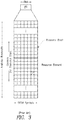
- a basic radio frame generally includes twenty slots which are paired together to form subframes, i.e., two slots for a subframe. In the more general sense, slots are combined to form subframes and subframes are combined to form frames.
- each slot of the basic radio frame generally includes multiple resource elements (REs) which can be illustrated as a resource grid including multiple frequency carriers and multiple orthogonal frequency division multiplexing (OFDM) symbols.
- REs resource elements
- OFDM orthogonal frequency division multiplexing
- one RE denotes a single OFDM symbol transmitted over a single frequency carrier.
- OFDM symbols and frequency carriers can be grouped as physical resource blocks (PRBs).
- An LTE PRB generally includes 7 OFDM symbols over 12 frequency carriers for a total of 84 REs per PRB. However, these quantities can vary.
- the network node 12 generates and transmits a PDCCH which informs each wireless device 16 whether and when data is to be transmitted to the wireless device 16 or received from the wireless device 16. According to the aforementioned communication standards, a wireless device 16 must decode the PDCCH successfully in order to receive and send data.
- the PDCCHs are located within the control region of a subframe which, as indicated above, usually occupies the first 3 OFDM symbols at the beginning of each transmitted subframe.
- the capacity of the PDCCH is a limiting factor in systems where there are a large number of wireless devices using low rate services such as voice over Internet protocol (VoIP). Indeed, due to the limited size of the control region, the number of PDCCHs than can be transmitted in any given subframe is limited.
- Release 11 of the LTE communication standards introduced an enhanced PDCCH (ePDCCH) which is transmitted on radio resources located within the data region of a subframe in which data are transmitted over physical downlink shared channels (PDSCH). Contrary to PDCCHs which are transmitted on radio resources distributed over the whole system bandwidth, ePDCCHs are transmitted on radio resources located on specific frequencies, or carriers, that can be allocated dynamically. In that regard, ePDCCHs employ frequency division multiplexing (FDM).
- FDM frequency division multiplexing
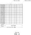
- the available bandwidth of a communication system can be partitioned into subbands, where each subband comprises a number of PRBs which depends on the available bandwidth.
- Table 1 below sets forth the number of PRBs per subband as a function of the number of PRBs supported by the system bandwidth. TABLE 1 System Bandwidth BW Subband Size (k) 6 - 7 NA 8 - 10 4 11 - 26 4 27 - 63 6 64 - 110 8
- each subband will comprise 4 PRBs for a total of 4 subbands.
- a wireless device can be provisioned with one or two sets of ePDCCH PRBs for ePDCCH monitoring.
- the ePDCCH PRB sets can consists of two, four or eight PRBs and the two sets maybe of different sizes.
- the location of these sets of PRBs and the configuration of these sets among the subbands can be provisioned as best suits the wireless device 16 and the network node 12, e.g., the eNodeB.
- subband feedback is provided by the wireless device 16 to the network node 12 to indicate which sections of the frequency spectrum are preferred by the wireless device 16.
- Subband feedback reports are sent often as the channel qualities experienced by the wireless device 16 can change quickly. However, as a network node 12 may service several wireless devices 16 at any given time, trying to act on every subband feedback reports sent by every wireless device 16 would add a significant processing burden on the network node 12.
- MCIM multi-cell interference management
- US 2014/0169200 A1 discloses multi-cell interference management (MCIM) for interference management among multiple cells in a wireless communication network.
- MCIM includes collecting data (e.g., CQI measurements and/or subband usage statistics) from a neighborhood of base stations; determining local and neighborhood system utility metrics; and determining interference managing directives (e.g., that can be communicated to the MAC layer of a base station in the neighborhood of base stations).
- a method and a node for determining radio resources for allocation to a downlink control channel in a communication network are provided according to the independent claims. Specific embodiments are defined by the dependent claims.
- a method includes receiving, over a predetermined measurement period, a plurality of reports from a wireless device, each report being indicative of a channel quality within at least a subband of an available bandwidth of the communication network. The method further includes for each subband for which at least one channel quality report has been received, determining a variance of the channel quality and an average of the channel quality over the predetermined measurement period. The method further includes determining subbands having at least a variance of the channel quality lower than a first threshold.
- the method further includes determining, from the subbands having at least a variance of the channel quality lower than the first threshold, subbands having an average of the channel quality greater than a second threshold. In some examples, the method further includes determining, from the subbands having at least a variance of the channel quality lower than the first threshold, a predetermined number of subbands having the highest average of the channel quality. In some examples, the method further includes reconfiguring an allocation of radio resources to the determined subbands if the determined subbands are different from current subbands used for transmitting the downlink control channels to the wireless device. In some examples, the method further includes reconfiguring an allocation of radio resources to the determined subbands if the reconfiguration would result in a more efficient allocation of radio resources.
- a more efficient allocation of radio resources is indicated when a variance of the channel quality of the currently used subbands is greater than the variance of the channel quality of the determined subbands. In some examples, a more efficient allocation of radio resources is indicated when an average of the channel quality of the currently used subbands is less that the average of the channel quality of the determined subbands. In some examples, the channel quality within a subband is at least based on a measure of a deviation of a channel quality indicator of the subband from a wideband channel quality indicator. In some examples, the predetermined measurement period is a radio resource control reconfiguration sequence period. In some examples, the predetermined measurement period is longer than a radio resource control reconfiguration sequence period.
- a node in a wireless communication network is configured to determine radio resources for allocation to a downlink control channel in the wireless communication network.
- the node comprises processing circuitry.
- the processing circuitry may include a memory and a processor.
- the processing circuitry is configured to receive, over a predetermined measurement period, a plurality of reports from a wireless device, each report being indicative of a channel quality within at least a subband of an available bandwidth of the communication network.
- the processing circuitry is also configured to determine, for each subband for which at least one channel quality report has been received, a variance of the channel quality and an average of the channel quality over the predetermined measurement period.
- the processing circuitry is also configured to determine subbands having at least a variance of the channel quality lower than a first threshold.
- the processing circuitry is further configured to determine, from the subbands having at least a variance of the channel quality lower than the first threshold, subbands having an average of the channel quality greater than a second threshold. In some examples, the processing circuitry is further configured to determine, from the subbands having at least a variance of the channel quality lower than the first threshold, a predetermined number of subbands having the highest average of the channel quality. In some examples, the processing circuitry is further configured to reconfigure an allocation of radio resources to the determined subbands if the determined subbands are different from current subbands used for transmitting the downlink control channels to the wireless device.
- the processing circuitry is further configured to reconfigure an allocation of radio resources to the determined subbands if the reconfiguration would result in a more efficient allocation of radio resources.
- a more efficient allocation of radio resources is indicated when a variance of the channel quality of the currently used subbands is greater than the variance of the channel quality of the determined subbands.
- a more efficient allocation of radio resources is indicated when an average of the channel quality of the currently used subbands is less than the average of the channel quality of the determined subbands.
- the channel quality within a subband is at least based on a measure of a deviation of a channel quality indicator of the subband from a wideband channel quality indicator.
- the predetermined measurement period is a radio resource control reconfiguration sequence period. In some examples, the predetermined measurement period is longer than a radio resource control reconfiguration sequence period.
- the embodiments reside primarily in combinations of apparatus components and processing steps related to a method and system for determining radio resources for allocation to a downlink control channel in a wireless communications network. Accordingly, the system and method components have been represented where appropriate by conventional symbols in the drawings, showing only those specific details that are pertinent to understanding the embodiments so as not to obscure the disclosure with details that will be readily apparent to those of ordinary skill in the art having the benefit of the description herein.
- relational terms such as “first” and “second,” “top” and “bottom,” and the like, may be used solely to distinguish one entity or element from another entity or element without necessarily requiring or implying any physical or logical relationship or order between such entities or elements.
- references to PDCCHs, ePDCCHs and eNBs are exemplary. Embodiments are not limited to LTE and may refer to control channels and base stations of other wireless access technologies.
- the term downlink control channel may include but not be limited to an ePDCCH and the term base station may include but not be limited to an eNB. Again, these terms are not used solely in the sense of LTE communications and may apply to other communication technologies that make use of various control channel(s).
- the term network node is not limited to a base station (or eNB) and can be any node in the wireless communication network that is configured to perform the functions of the network node described herein.
- methods are provided to identify subbands of the available bandwidth of a communication system having a high channel quality according to one or more criteria in order to allocate radio resources among such subbands for transmission of the downlink control channels.
- radio resources for transmission of the downlink control channels may be employed for the transmission of the downlink control channels, which may further result in increased control channel capacity, increased control channel robustness, lower processing overhead of the base station, and increased control channel performance for wireless devices experiencing slowly changing channels.
- FIG. 5 a block diagram of a wireless communication network with a network node 22 configured to perform channel quality based radio resource allocation for downlink control channels according to the methods described herein.
- the network node 22 receives a plurality of channel quality measurement reports from a wireless device 16 over a predetermined measurement period. Each channel quality measurement report indicates a channel quality within a subband.
- the channel quality may be reported as a channel quality indicator, CQI, or as a differential CQI.
- a variance of the channel quality over the measurement period and an average of the channel quality over the measurement period are determined by the network node 22 from the channel quality measurement reports.
- Subbands having at least a variance of the channel quality lower than a first threshold are first determined.
- one or more subbands are further determined for use in transmitting the downlink control channels.
- radio resources for transmitting the downlink control channels may be allocated to the determined subbands.
- these further determined subbands are those having an average of the channel quality greater than a second threshold.
- these further determined subbands are a predetermined number of subbands exhibiting the highest average of the channel quality.
- Data is therefore recorded for the duration of the measurement period, and at the end of the measurement period, a statistical analysis of the channel quality reported for each subband is performed to evaluate the subband for viability for the downlink control channels.
- statistics used in the statistical analysis are the variance of the channel quality of the subband over the measurement period and the average or mean value of the channel quality of the subband over the measurement period.
- Good candidate subbands for use in transmitting the downlink control channels to the wireless device are generally the subbands having a combination of low variance of channel quality yet a high average of channel quality over the measurement period.
- candidate subbands are the ones having a variance of the channel quality lower than a first threshold and an average value of the channel quality exceeding a second threshold.
- the variance is the primary determiner when selecting, or pre-selecting, a subband for downlink control channel transmission.
- FIG. 6 illustrates channel quality variance analysis
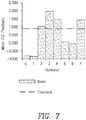
- FIG. 7 illustrates average channel quality analysis.
- FIG. 6 is a bar graph of variance over the measurement period of channel quality versus subbands for the eight subbands of this example.
- the subbands having a variance less than a first threshold of 0.2 shown as a dashed line in this example are subbands 0, 1, 2, 3 and 6.
- FIG. 7 is a bar graph of average value of channel quality, measured as averages of CQI, over a measurement period versus subbands for the eight subbands.
- a second threshold value of 1.00 in this example is shown as a dashed line.
- the subbands having an average CQI above this threshold are subbands 2, 3, 4 and 7.
- the subbands having a variance less than the first threshold of 0.2 and having an average greater than the second threshold of 1.0 are subbands 2 and 3.
- these subbands may be selected for allocation of radio resources for transmission of the downlink control channels.
- the number of subbands may be less than or greater than eight and the thresholds may be different than 0.2 and 1.0. Note that, in this example, although subband 7 has a high average CQI value during the measurement period, subband 7 is not selected because it has a variance well above the first threshold.
- the channel quality (e.g. CQI) of a subband may be based at least in part on a deviation of a channel quality of the subband from a wideband channel quality, that is, a channel quality for the whole available bandwidth.
- the channel quality for a given subband may be encoded differentially relative to the wideband channel quality.
- the different CQI value may be mapped as shown in Table 2. TABLE 2 Differential CQI value Offset level 0 ⁇ 1 1 2 2 3 3 ⁇ 4
- the differential channel quality may be used in the calculations of the channel quality variance and channel quality average for each subband.
- the relative channel qualities e.g. the differential CQI values
- the candidate subbands can be identified even under conditions where the wideband channel quality is fluctuating.
- FIG. 8 is a block diagram of a network node 22 configured to determine radio resources for allocation to a downlink control channel in a communication network.
- the base station 22 has processing circuitry 24 and a transceiver 26.
- the processing circuitry 24 may include a memory 28 and a processor 30.
- the memory 28 contains instructions which, when executed by the processor 30, configure the processor 30 to perform the one or more of the functions described herein.
- determination of the resources for allocation to a downlink control channel for a wireless device 16 based on subband channel quality as described herein may typically be performed in a base station such as an eNodeB which serves the wireless device 16 and actually transmits the downlink control channel.
- the determination may be performed in another network node 22 of a wireless communication network such as a mobile management entity (MME) or serving gateway (SGW).
- MME mobile management entity
- SGW serving gateway
- the processing circuitry 24 may comprise integrated circuitry for processing and/or control, e.g., one or more processors and/or processor cores and/or FPGAs (Field Programmable Gate Array) and/or ASICs (Application Specific Integrated Circuitry).
- Processing circuitry 24 may comprise and/or be connected to and/or be adapted for accessing (e.g., writing to and/or reading from) memory 28, which may comprise any kind of volatile and/or non-volatile memory, e.g., cache and/or buffer memory and/or RAM (Random Access Memory) and/or ROM (Read-Only Memory) and/or optical memory and/or EPROM (Erasable Programmable Read-Only Memory).
- memory 28 may be adapted to store code executable by control circuitry and/or other data, e.g., data pertaining to communication, e.g., configuration and/or address data of nodes, etc.
- Processing circuitry 24 may be configured to perform any of the methods described herein and/or to cause such methods to be performed, e.g., by the base station 22. Corresponding instructions may be stored in the memory 28, which may be readable and/or readably connected to the processing circuitry 24.
- processing circuitry 24 may include a controller, which may comprise a microprocessor and/or microcontroller and/or FPGA (Field-Programmable Gate Array) device and/or ASIC (Application Specific Integrated Circuit) device. It may be considered that processing circuitry 24 includes or may be connected or connectable to memory, which may be adapted to be accessible for reading and/or writing by the controller and/or processing circuitry 24.
- the memory 28 is configured to store channel quality reports 32, each report being indicative of a channel quality within a subband of an available bandwidth of the communication network of which the base station 22 is a part.
- the memory 28 is also configured to store channel quality statistics 34 which may include a variance and an average of the channel quality over a predetermined measurement period for each subband.
- the processing circuitry 24 is configured to perform statistics determination 36 and subband determination 38.
- Statistics determination 36 may include determining the variance and the average of channel quality based on the stored channel quality reports.
- Subband determination 38 may include determining subbands having at least a variance of the channel quality lower than a first threshold. Subband determination 38 may include, in some embodiments, determining, from the subbands having at least a variance of the channel quality lower than the first threshold, subbands having an average of the channel quality greater than a second threshold. Subband determination 38 may include, in some embodiments, determining, from the subbands having at least a variance of the channel quality lower than the first threshold, a predetermined number of subbands having the highest average of the channel quality.
- Radio resource allocation reconfiguration 39 may include reconfiguring an allocation of radio resources to the determined subbands if the determined subbands are different from current subbands used for transmitting the downlink control channels.
- the transceiver 26 transmits the determined subband identities to the wireless device whose channel quality was reported during the measurement period so that the wireless device knows on which subbands to listen for the downlink control channels.
- the transceiver 26 also receives the channel quality reports and transmits the downlink control channels.
- the network node 40 includes a memory module 42 which is configured to store channel quality reports 44 and channel quality statistics 46.
- the network node 40 also includes modules that include a receiver module 48 configured to receive a plurality of channel quality reports from a wireless device, each report being indicative of a channel quality within at least a subband of an available bandwidth of the communication network, a determiner module 50 configured to determine variances and averages of channel quality over a predetermined measurement period, and a determiner module 54 configured to determine subbands having at least a channel quality variance less than a first threshold and possibly also a channel quality average greater than a second threshold.
- the network node 40 may also comprise a reconfiguration module 56 configured to reconfigure radio resources for transmitting the downlink control channel in the determined subbands.
- a transmitter module 58 transmits the downlink control channel.
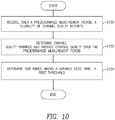
- FIG. 10 is a flowchart of an exemplary process of determining radio resources for allocation to a downlink control channel in a communication network.
- the process includes receiving, over a predetermined measurement period, a plurality of channel quality reports (block S100) from a wireless device.
- Each report is indicative of a channel quality within a subband of an available bandwidth of the communication network.
- the reports are received by the network node 22.
- the predetermined measurement period may be a radio resource control reconfiguration sequence period and may be longer than a radio resource control reconfiguration sequence period.
- a radio resource control reconfiguration sequence period is the time it takes for the radio resource control reconfiguration request message to be sent and the radio resource control reconfiguration response to be received by the system. Such period may include latencies incurred in a loaded system.
- Subbands that have at least a variance lower than a first threshold are then determined (block S104). From these subbands having at least a variance lower than the first threshold, one or more subbands are further determined. In some embodiments, the subbands having an average of the channel quality higher than a second threshold are further determined. In some other embodiments, a predetermined number of subbands having the highest average of the channel quality are further determined. The identities of these determined subbands may be transmitted to the wireless device.
- the process may further include reconfiguring an allocation of radio resources to the determined subbands if the determined subbands are different from current subbands used for transmitting the downlink control channels to the wireless device.
- reallocation of the radio resources based on the determined subbands is performed if the reallocation would result in a more efficient allocation of radio resources.
- a more efficient allocation of resources is indicated when a variance of the channel quality of currently used subbands is greater than a variance of the channel quality of the determined subbands.
- a more efficient allocation of resources may be indicated when an average of the channel quality of the currently used subbands is less that the average of the channel quality of the determined subbands.
- a more efficient allocation of resources is indicated only when both the variance of the channel quality of the currently used subbands is greater than a variance of the channel quality of the determined subbands and the average of the channel quality of the currently used subbands is less that the average of the channel quality of the determined subbands.
- the subbands determined to meet the quality criteria may be aggregated in order to further refine the selection of subbands.
- subbands instead of selecting subbands for resource allocation after one measurement period, subbands may be selected after several consecutive measurement periods.
- FIG. 11 shows an example timeline for receiving, aggregating and filtering candidate subbands according to some embodiments. Under the timeline, several consecutive measurement periods are shown with the subbands (identified by number) that have been considered viable for transmitting downlink control channels. In some embodiments, a predetermined number of these several consecutive measurement periods may amount to a longer measurement period, i.e. an extended measurement period.
- subbands determined to meet the quality criteria in at least half of the consecutive measurement periods of the extended measurement period may be selected for transmission of the downlink control channels. According to such embodiments, subbands 0, 1, 3 and 6 would be selected in the example. In some embodiments, subbands determined to meet the quality criteria in a majority of the consecutive measurement periods of the extended measurement period may be selected for transmission of the downlink control channels. In such embodiments, subbands 0, 3 and 6 would be selected in the example. In other embodiments, subbands determined to meet the quality criteria in all of the consecutive measurement periods of the extended measurement period may be selected for transmission of the downlink control channels. In such embodiments, only subbands 0 and 6 would be selected in the example. In some embodiments, the extended measurement period may be a radio resource control reconfiguration sequence period. In some embodiments, the extended measurement period may be longer than the radio resource control reconfiguration sequence period.
- the concepts described herein may be embodied as a method, data processing system, and/or computer program product. Accordingly, the concepts described herein may take the form of an entirely hardware embodiment, an entirely software embodiment or an embodiment combining software and hardware aspects all generally referred to herein as a "circuit" or "module.” Furthermore, the disclosure may take the form of a computer program product on a tangible computer usable storage medium having computer program code embodied in the medium that can be executed by a computer. Any suitable tangible computer readable medium may be utilized including hard disks, CD-ROMs, electronic storage devices, optical storage devices, or magnetic storage devices.
- These computer program instructions may also be stored in a computer readable memory or storage medium that can direct a computer or other programmable data processing apparatus to function in a particular manner, such that the instructions stored in the computer readable memory produce an article of manufacture including instruction means which implement the function/act specified in the flowchart and/or block diagram block or blocks.
- the computer program instructions may also be loaded onto a computer or other programmable data processing apparatus to cause a series of operational steps to be performed on the computer or other programmable apparatus to produce a computer implemented process such that the instructions which execute on the computer or other programmable apparatus provide steps for implementing the functions/acts specified in the flowchart and/or block diagram block or blocks.
- Computer program code for carrying out operations of the concepts described herein may be written in an object oriented programming language such as Java® or C++.
- the computer program code for carrying out operations of the disclosure may also be written in conventional procedural programming languages, such as the "C" programming language.
- the program code may execute entirely on the user's computer, partly on the user's computer, as a stand-alone software package, partly on the user's computer and partly on a remote computer or entirely on the remote computer.
- the remote computer may be connected to the user's computer through a local area network (LAN) or a wide area network (WAN), or the connection may be made to an external computer (for example, through the Internet using an Internet Service Provider).
- LAN local area network
- WAN wide area network
- Internet Service Provider for example, AT&T, MCI, Sprint, EarthLink, MSN, GTE, etc.
Landscapes
- Engineering & Computer Science (AREA)
- Signal Processing (AREA)
- Computer Networks & Wireless Communication (AREA)
- Quality & Reliability (AREA)
- Mobile Radio Communication Systems (AREA)
Claims (12)
- Verfahren zum Bestimmen von Funkressourcen zum Zuordnen zu einem Abwärtsstreckensteuerkanal in einem Kommunikationsnetzwerk, wobei das Verfahren umfasst:Empfangen einer Vielzahl von Berichten von einer drahtlosen Vorrichtung (16) über eine vorbestimmte Messperiode (18), wobei jeder Bericht eine Kanalqualität innerhalb mindestens eines Teilbands einer verfügbaren Bandbreite des Kommunikationsnetzwerks angibt (S100);für jedes Teilband, für das mindestens ein Kanalqualitätsbericht empfangen wurde, Bestimmen einer Varianz der Kanalqualität und eines Durchschnitts der Kanalqualität über die vorbestimmte Messperiode (18) (S102);Bestimmen von Teilbändern, die mindestens eine Varianz der Kanalqualität aufweisen, die geringer als eine erste Schwelle (S104) ist; undBestimmen aus den Teilbändern, die mindestens eine Varianz der Kanalqualität aufweisen, die geringer als die erste Schwelle ist, von Teilbändern, die einen Durchschnitt der Kanalqualität aufweisen, der größer als eine zweite Schwelle ist.
- Verfahren nach Anspruch 1, ferner umfassend das Rekonfigurieren einer Zuordnung von Funkressourcen zu den bestimmten Teilbändern, falls sich die ermittelten Teilbänder von den aktuellen Teilbändern unterscheiden, die zum Übertragen der Abwärtsstreckensteuerkanäle an die drahtlose Vorrichtung verwendet werden.
- Verfahren nach Anspruch 1, ferner umfassend das Rekonfigurieren einer Zuordnung von Funkressourcen zu den bestimmten Teilbändern, falls die Rekonfiguration zu einer effizienteren Zuordnung von Funkressourcen führen würde.
- Verfahren nach Anspruch 3, wobei eine effizientere Zuordnung von Funkressourcen angegeben wird, wenn eine Varianz der Kanalqualität der aktuell verwendeten Teilbänder größer ist als die Varianz der Kanalqualität der bestimmten Teilbänder, oder
wobei eine effizientere Zuordnung von Funkressourcen angegeben wird, wenn ein Durchschnitt der Kanalqualität der aktuell verwendeten Teilbänder geringer ist als der Durchschnitt der Kanalqualität der bestimmten Teilbänder. - Verfahren nach Anspruch 1, wobei die Kanalqualität innerhalb eines Teilbands mindestens auf einem Maß einer Abweichung eines Kanalqualitätsindikators des Teilbands von einem Breitband-Kanalqualitätsindikator basiert.
- Verfahren nach Anspruch 1, wobei die vorbestimmte Messperiode (18) eine Funkressourcensteuerungs-Rekonfigurationssequenzperiode ist, oder
wobei die vorbestimmte Messperiode (18) länger als eine Funkressourcensteuerungs-Rekonfigurationssequenzperiode ist. - Knoten in einem drahtlosen Kommunikationsnetzwerk, das zum Bestimmen von Funkressourcen zur Zuordnung zu einem Abwärtsstreckensteuerkanal in dem drahtlosen Kommunikationsnetzwerk konfiguriert ist, wobei der Knoten (22) umfasst:eine Verarbeitungsschaltung (24), die konfiguriert ist zum:Empfangen einer Vielzahl von Berichten von einer drahtlosen Vorrichtung über eine vorbestimmte Messperiode, wobei jeder Bericht eine Kanalqualität innerhalb mindestens eines Teilbands einer verfügbaren Bandbreite des Kommunikationsnetzwerks angibt;Bestimmen, für jedes Teilband, für das mindestens ein Kanalqualitätsbericht empfangen wurde, einer Varianz der Kanalqualität und eines Durchschnitts der Kanalqualität über die vorbestimmte Messperiode;Bestimmen von Teilbändern, die mindestens eine Varianz der Kanalqualität aufweisen, die geringer als eine erste Schwelle ist; undBestimmen aus den Teilbändern, die mindestens eine Varianz der Kanalqualität aufweisen, die geringer als die erste Schwelle ist,von Teilbändern, die einen Durchschnitt der Kanalqualität aufweisen, der größer als eine zweite Schwelle ist.
- Knoten nach Anspruch 7, wobei die Verarbeitungsschaltung ferner konfiguriert ist zum Rekonfigurieren einer Zuordnung von Funkressourcen zu den bestimmten Teilbändern, falls sich die ermittelten Teilbänder von den aktuellen Teilbändern unterscheiden, die zum Übertragen der Abwärtsstreckensteuerkanäle an die drahtlose Vorrichtung verwendet werden.
- Knoten nach Anspruch 7, wobei die Verarbeitungsschaltung ferner konfiguriert ist zum Rekonfigurieren einer Zuordnung von Funkressourcen zu den bestimmten Teilbändern, falls die Rekonfiguration zu einer effizienteren Zuordnung von Funkressourcen führen würde.
- Knoten nach Anspruch 9, wobei eine effizientere Zuordnung von Funkressourcen angegeben wird, wenn eine Abweichung der Kanalqualität der aktuell verwendeten Teilbänder größer ist als die Abweichung der Kanalqualität der bestimmten Teilbänder, oder
wobei eine effizientere Zuordnung von Funkressourcen angegeben wird, wenn ein Durchschnitt der Kanalqualität der aktuell verwendeten Teilbänder geringer ist als der Durchschnitt der Kanalqualität der bestimmten Teilbänder. - Knoten nach Anspruch 7, wobei die Kanalqualität innerhalb eines Teilbands ein Maß einer Abweichung eines Kanalqualitätsindikators des Teilbands von einem Breitband-Kanalqualitätsindikator ist.
- Knoten nach Anspruch 7, wobei die vorbestimmte Messperiode (18) eine Funkressourcensteuerungs-Rekonfigurationssequenzperiode ist, oder
wobei die vorbestimmte Messperiode (18) länger als eine Funkressourcensteuerungs-Rekonfigurationssequenzperiode ist.
Applications Claiming Priority (1)
| Application Number | Priority Date | Filing Date | Title |
|---|---|---|---|
| PCT/IB2015/058652 WO2017081509A1 (en) | 2015-11-09 | 2015-11-09 | Feedback assisted downlink control channel configuration |
Publications (2)
| Publication Number | Publication Date |
|---|---|
| EP3375240A1 EP3375240A1 (de) | 2018-09-19 |
| EP3375240B1 true EP3375240B1 (de) | 2019-09-11 |
Family
ID=54695798
Family Applications (1)
| Application Number | Title | Priority Date | Filing Date |
|---|---|---|---|
| EP15798239.8A Not-in-force EP3375240B1 (de) | 2015-11-09 | 2015-11-09 | Rückkopplungsunterstützte downlink-steuerkanalkonfiguration |
Country Status (4)
| Country | Link |
|---|---|
| US (1) | US10728907B2 (de) |
| EP (1) | EP3375240B1 (de) |
| CN (1) | CN108353413B (de) |
| WO (1) | WO2017081509A1 (de) |
Families Citing this family (4)
| Publication number | Priority date | Publication date | Assignee | Title |
|---|---|---|---|---|
| US10820340B2 (en) * | 2018-06-22 | 2020-10-27 | At&T Intellectual Property I, L.P. | Facilitation of frequency selective scheduling for 5G or other next generation network |
| CN114765483B (zh) * | 2021-01-15 | 2025-04-08 | 维沃移动通信有限公司 | 信道状态信息的上报方法、装置及终端 |
| WO2022170517A1 (en) * | 2021-02-09 | 2022-08-18 | Telefonaktiebolaget Lm Ericsson (Publ) | Method and apparatus for determining channel parameter |
| JP7746938B2 (ja) * | 2022-08-01 | 2025-10-01 | トヨタ自動車株式会社 | 通信制御方法及び通信システム |
Family Cites Families (18)
| Publication number | Priority date | Publication date | Assignee | Title |
|---|---|---|---|---|
| KR100620914B1 (ko) * | 2004-04-07 | 2006-09-13 | 삼성전자주식회사 | 광대역 무선통신시스템에서 에이엠씨 모드와 다이버시티 모드를 스위칭하기 위한 장치 및 방법 |
| KR100606083B1 (ko) * | 2004-11-04 | 2006-07-31 | 삼성전자주식회사 | 광대역 무선 접속 통신 시스템에서 부채널 할당 시스템 및 방법 |
| CN100579100C (zh) * | 2006-06-20 | 2010-01-06 | 华为技术有限公司 | 一种频域调度方法 |
| US8194765B2 (en) * | 2008-05-05 | 2012-06-05 | Motorola Solutions, Inc. | Method and apparatus for configuring channel quality feedback in an orthogonal frequency division multiplexing communication system |
| US8493874B2 (en) * | 2008-05-05 | 2013-07-23 | Motorola Mobility Llc | Method and apparatus for providing channel quality feedback in an orthogonal frequency division multiplexing communication system |
| US8355360B2 (en) * | 2008-05-14 | 2013-01-15 | Motorola Mobility Llc | Method and apparatus for allocating downlink power in an orthogonal frequency division multiplexing communication system |
| CN102547997B (zh) | 2010-12-15 | 2016-01-13 | 上海贝尔股份有限公司 | 在无线通信系统中基于干扰进行自适应调度的方法与设备 |
| US8811207B2 (en) | 2011-10-28 | 2014-08-19 | Nokia Corporation | Allocating control data to user equipment |
| US8780863B2 (en) | 2011-11-01 | 2014-07-15 | Futurewei Technologies, Inc. | Systems and methods for control channel transmission and reception |
| US9572148B2 (en) | 2011-12-07 | 2017-02-14 | Lg Electronics Inc. | Method and apparatus for transceiving a downlink control channel in a wireless communication system |
| US9516636B2 (en) | 2011-12-07 | 2016-12-06 | Lg Electronics Inc. | Method and apparatus for transceiving a downlink control channel in a wireless communication system |
| WO2013157899A1 (ko) | 2012-04-20 | 2013-10-24 | 엘지전자 주식회사 | 채널 상태 보고 방법 및 이를 위한 장치 |
| GB2501917A (en) | 2012-05-10 | 2013-11-13 | Nec Corp | Communication system |
| CN104769879B (zh) | 2012-11-02 | 2018-11-20 | 华为技术有限公司 | 网络控制节点中的方法 |
| US9106358B2 (en) | 2012-12-18 | 2015-08-11 | Airhop Communications, Inc. | Multi-cell interference management |
| WO2015127593A1 (zh) * | 2014-02-25 | 2015-09-03 | 华为技术有限公司 | 频谱处理的方法、基站、用户设备及系统 |
| US9692554B2 (en) * | 2014-10-29 | 2017-06-27 | Texas Instruments Incorporated | Power line communication operating frequency band selection apparatus, systems and methods |
| US9871642B2 (en) * | 2015-06-25 | 2018-01-16 | Telefonaktiebolaget Lm Ericsson (Publ) | Enabling higher-order modulation in a cellular network |
-
2015
- 2015-11-09 EP EP15798239.8A patent/EP3375240B1/de not_active Not-in-force
- 2015-11-09 US US15/767,854 patent/US10728907B2/en active Active
- 2015-11-09 WO PCT/IB2015/058652 patent/WO2017081509A1/en not_active Ceased
- 2015-11-09 CN CN201580084458.2A patent/CN108353413B/zh not_active Expired - Fee Related
Non-Patent Citations (1)
| Title |
|---|
| None * |
Also Published As
| Publication number | Publication date |
|---|---|
| US10728907B2 (en) | 2020-07-28 |
| WO2017081509A1 (en) | 2017-05-18 |
| EP3375240A1 (de) | 2018-09-19 |
| CN108353413A (zh) | 2018-07-31 |
| US20180310320A1 (en) | 2018-10-25 |
| CN108353413B (zh) | 2023-08-18 |
Similar Documents
| Publication | Publication Date | Title |
|---|---|---|
| RU2609135C1 (ru) | Способ координации помех между сотами | |
| CN102204310B (zh) | 资源分配方法、装置和基站 | |
| JP7058605B2 (ja) | スケジュールタイミング間隔を判定するための方法および装置 | |
| US8830936B2 (en) | Allocating control channel elements to downlink control channels | |
| JP5452705B2 (ja) | 物理アップリンク共有チャネル(pusch)における定期的フィードバック情報の送信の構成 | |
| US20230120039A1 (en) | Transmission of measurement reports in a wireless communication system | |
| CN102958133B (zh) | 接入通信系统的方法、下行信息发送方法、终端及基站 | |
| CN113574948A (zh) | 用于复用uci的方法和装备 | |
| CN103139924A (zh) | 一种调度资源的方法及装置 | |
| EP3602904B1 (de) | Erweiterte planungsanfrage (sr) für verbesserte planungsinformationsanzeige | |
| CA2886245A1 (en) | Control channel detection method and user equipment | |
| US11153901B2 (en) | Method for determining time information, network node, and terminal device | |
| CN112970221A (zh) | 用于双连接的物理下行链路控制信道限制 | |
| US10985884B2 (en) | Search space configuration for short transmission time interval | |
| EP3375240B1 (de) | Rückkopplungsunterstützte downlink-steuerkanalkonfiguration | |
| CN108141764A (zh) | 一种干扰指示方法及装置 | |
| KR20220051845A (ko) | 셀룰러 운송파 묶음에 걸친 다운링크 스케줄링 | |
| CN111294191B (zh) | 数据传输方法及装置 | |
| EP3363135B1 (de) | Zuweisung von downlink-steuerkanalressourcen | |
| CN105874836B (zh) | 一种控制信息处理的方法、装置和系统 | |
| CN102404797B (zh) | Lte系统中cfi信息的传输和获取方法、及发送和接收装置 | |
| WO2012083659A1 (zh) | 一种干扰消除的资源分配方法和装置 | |
| EP3420770B1 (de) | Passivintermodulationsformung | |
| CN102227944B (zh) | 资源分配方法、通信系统、基站以及程序 | |
| CN105612777B (zh) | 测量信道质量的方法、用户设备和发送端 |
Legal Events
| Date | Code | Title | Description |
|---|---|---|---|
| STAA | Information on the status of an ep patent application or granted ep patent |
Free format text: STATUS: THE INTERNATIONAL PUBLICATION HAS BEEN MADE |
|
| PUAI | Public reference made under article 153(3) epc to a published international application that has entered the european phase |
Free format text: ORIGINAL CODE: 0009012 |
|
| STAA | Information on the status of an ep patent application or granted ep patent |
Free format text: STATUS: REQUEST FOR EXAMINATION WAS MADE |
|
| 17P | Request for examination filed |
Effective date: 20180528 |
|
| AK | Designated contracting states |
Kind code of ref document: A1 Designated state(s): AL AT BE BG CH CY CZ DE DK EE ES FI FR GB GR HR HU IE IS IT LI LT LU LV MC MK MT NL NO PL PT RO RS SE SI SK SM TR |
|
| AX | Request for extension of the european patent |
Extension state: BA ME |
|
| DAV | Request for validation of the european patent (deleted) | ||
| DAX | Request for extension of the european patent (deleted) | ||
| GRAP | Despatch of communication of intention to grant a patent |
Free format text: ORIGINAL CODE: EPIDOSNIGR1 |
|
| STAA | Information on the status of an ep patent application or granted ep patent |
Free format text: STATUS: GRANT OF PATENT IS INTENDED |
|
| RIC1 | Information provided on ipc code assigned before grant |
Ipc: H04L 5/00 20060101ALI20190131BHEP Ipc: H04W 72/12 20090101AFI20190131BHEP |
|
| INTG | Intention to grant announced |
Effective date: 20190227 |
|
| GRAJ | Information related to disapproval of communication of intention to grant by the applicant or resumption of examination proceedings by the epo deleted |
Free format text: ORIGINAL CODE: EPIDOSDIGR1 |
|
| STAA | Information on the status of an ep patent application or granted ep patent |
Free format text: STATUS: REQUEST FOR EXAMINATION WAS MADE |
|
| INTC | Intention to grant announced (deleted) | ||
| GRAR | Information related to intention to grant a patent recorded |
Free format text: ORIGINAL CODE: EPIDOSNIGR71 |
|
| GRAS | Grant fee paid |
Free format text: ORIGINAL CODE: EPIDOSNIGR3 |
|
| STAA | Information on the status of an ep patent application or granted ep patent |
Free format text: STATUS: GRANT OF PATENT IS INTENDED |
|
| GRAA | (expected) grant |
Free format text: ORIGINAL CODE: 0009210 |
|
| STAA | Information on the status of an ep patent application or granted ep patent |
Free format text: STATUS: THE PATENT HAS BEEN GRANTED |
|
| AK | Designated contracting states |
Kind code of ref document: B1 Designated state(s): AL AT BE BG CH CY CZ DE DK EE ES FI FR GB GR HR HU IE IS IT LI LT LU LV MC MK MT NL NO PL PT RO RS SE SI SK SM TR |
|
| INTG | Intention to grant announced |
Effective date: 20190807 |
|
| REG | Reference to a national code |
Ref country code: GB Ref legal event code: FG4D |
|
| REG | Reference to a national code |
Ref country code: CH Ref legal event code: EP |
|
| REG | Reference to a national code |
Ref country code: AT Ref legal event code: REF Ref document number: 1180137 Country of ref document: AT Kind code of ref document: T Effective date: 20190915 |
|
| REG | Reference to a national code |
Ref country code: DE Ref legal event code: R096 Ref document number: 602015037896 Country of ref document: DE |
|
| REG | Reference to a national code |
Ref country code: IE Ref legal event code: FG4D |
|
| REG | Reference to a national code |
Ref country code: NL Ref legal event code: MP Effective date: 20190911 |
|
| REG | Reference to a national code |
Ref country code: LT Ref legal event code: MG4D |
|
| PG25 | Lapsed in a contracting state [announced via postgrant information from national office to epo] |
Ref country code: SE Free format text: LAPSE BECAUSE OF FAILURE TO SUBMIT A TRANSLATION OF THE DESCRIPTION OR TO PAY THE FEE WITHIN THE PRESCRIBED TIME-LIMIT Effective date: 20190911 Ref country code: LT Free format text: LAPSE BECAUSE OF FAILURE TO SUBMIT A TRANSLATION OF THE DESCRIPTION OR TO PAY THE FEE WITHIN THE PRESCRIBED TIME-LIMIT Effective date: 20190911 Ref country code: BG Free format text: LAPSE BECAUSE OF FAILURE TO SUBMIT A TRANSLATION OF THE DESCRIPTION OR TO PAY THE FEE WITHIN THE PRESCRIBED TIME-LIMIT Effective date: 20191211 Ref country code: HR Free format text: LAPSE BECAUSE OF FAILURE TO SUBMIT A TRANSLATION OF THE DESCRIPTION OR TO PAY THE FEE WITHIN THE PRESCRIBED TIME-LIMIT Effective date: 20190911 Ref country code: FI Free format text: LAPSE BECAUSE OF FAILURE TO SUBMIT A TRANSLATION OF THE DESCRIPTION OR TO PAY THE FEE WITHIN THE PRESCRIBED TIME-LIMIT Effective date: 20190911 Ref country code: NO Free format text: LAPSE BECAUSE OF FAILURE TO SUBMIT A TRANSLATION OF THE DESCRIPTION OR TO PAY THE FEE WITHIN THE PRESCRIBED TIME-LIMIT Effective date: 20191211 |
|
| PG25 | Lapsed in a contracting state [announced via postgrant information from national office to epo] |
Ref country code: LV Free format text: LAPSE BECAUSE OF FAILURE TO SUBMIT A TRANSLATION OF THE DESCRIPTION OR TO PAY THE FEE WITHIN THE PRESCRIBED TIME-LIMIT Effective date: 20190911 Ref country code: ES Free format text: LAPSE BECAUSE OF FAILURE TO SUBMIT A TRANSLATION OF THE DESCRIPTION OR TO PAY THE FEE WITHIN THE PRESCRIBED TIME-LIMIT Effective date: 20190911 Ref country code: AL Free format text: LAPSE BECAUSE OF FAILURE TO SUBMIT A TRANSLATION OF THE DESCRIPTION OR TO PAY THE FEE WITHIN THE PRESCRIBED TIME-LIMIT Effective date: 20190911 Ref country code: RS Free format text: LAPSE BECAUSE OF FAILURE TO SUBMIT A TRANSLATION OF THE DESCRIPTION OR TO PAY THE FEE WITHIN THE PRESCRIBED TIME-LIMIT Effective date: 20190911 Ref country code: GR Free format text: LAPSE BECAUSE OF FAILURE TO SUBMIT A TRANSLATION OF THE DESCRIPTION OR TO PAY THE FEE WITHIN THE PRESCRIBED TIME-LIMIT Effective date: 20191212 |
|
| REG | Reference to a national code |
Ref country code: AT Ref legal event code: MK05 Ref document number: 1180137 Country of ref document: AT Kind code of ref document: T Effective date: 20190911 |
|
| PG25 | Lapsed in a contracting state [announced via postgrant information from national office to epo] |
Ref country code: AT Free format text: LAPSE BECAUSE OF FAILURE TO SUBMIT A TRANSLATION OF THE DESCRIPTION OR TO PAY THE FEE WITHIN THE PRESCRIBED TIME-LIMIT Effective date: 20190911 Ref country code: PT Free format text: LAPSE BECAUSE OF FAILURE TO SUBMIT A TRANSLATION OF THE DESCRIPTION OR TO PAY THE FEE WITHIN THE PRESCRIBED TIME-LIMIT Effective date: 20200113 Ref country code: EE Free format text: LAPSE BECAUSE OF FAILURE TO SUBMIT A TRANSLATION OF THE DESCRIPTION OR TO PAY THE FEE WITHIN THE PRESCRIBED TIME-LIMIT Effective date: 20190911 Ref country code: NL Free format text: LAPSE BECAUSE OF FAILURE TO SUBMIT A TRANSLATION OF THE DESCRIPTION OR TO PAY THE FEE WITHIN THE PRESCRIBED TIME-LIMIT Effective date: 20190911 Ref country code: RO Free format text: LAPSE BECAUSE OF FAILURE TO SUBMIT A TRANSLATION OF THE DESCRIPTION OR TO PAY THE FEE WITHIN THE PRESCRIBED TIME-LIMIT Effective date: 20190911 Ref country code: IT Free format text: LAPSE BECAUSE OF FAILURE TO SUBMIT A TRANSLATION OF THE DESCRIPTION OR TO PAY THE FEE WITHIN THE PRESCRIBED TIME-LIMIT Effective date: 20190911 Ref country code: PL Free format text: LAPSE BECAUSE OF FAILURE TO SUBMIT A TRANSLATION OF THE DESCRIPTION OR TO PAY THE FEE WITHIN THE PRESCRIBED TIME-LIMIT Effective date: 20190911 |
|
| PG25 | Lapsed in a contracting state [announced via postgrant information from national office to epo] |
Ref country code: SM Free format text: LAPSE BECAUSE OF FAILURE TO SUBMIT A TRANSLATION OF THE DESCRIPTION OR TO PAY THE FEE WITHIN THE PRESCRIBED TIME-LIMIT Effective date: 20190911 Ref country code: IS Free format text: LAPSE BECAUSE OF FAILURE TO SUBMIT A TRANSLATION OF THE DESCRIPTION OR TO PAY THE FEE WITHIN THE PRESCRIBED TIME-LIMIT Effective date: 20200224 Ref country code: CZ Free format text: LAPSE BECAUSE OF FAILURE TO SUBMIT A TRANSLATION OF THE DESCRIPTION OR TO PAY THE FEE WITHIN THE PRESCRIBED TIME-LIMIT Effective date: 20190911 Ref country code: SK Free format text: LAPSE BECAUSE OF FAILURE TO SUBMIT A TRANSLATION OF THE DESCRIPTION OR TO PAY THE FEE WITHIN THE PRESCRIBED TIME-LIMIT Effective date: 20190911 |
|
| REG | Reference to a national code |
Ref country code: DE Ref legal event code: R097 Ref document number: 602015037896 Country of ref document: DE |
|
| REG | Reference to a national code |
Ref country code: CH Ref legal event code: PL |
|
| PLBE | No opposition filed within time limit |
Free format text: ORIGINAL CODE: 0009261 |
|
| STAA | Information on the status of an ep patent application or granted ep patent |
Free format text: STATUS: NO OPPOSITION FILED WITHIN TIME LIMIT |
|
| PG2D | Information on lapse in contracting state deleted |
Ref country code: IS |
|
| PG25 | Lapsed in a contracting state [announced via postgrant information from national office to epo] |
Ref country code: LI Free format text: LAPSE BECAUSE OF NON-PAYMENT OF DUE FEES Effective date: 20191130 Ref country code: MC Free format text: LAPSE BECAUSE OF FAILURE TO SUBMIT A TRANSLATION OF THE DESCRIPTION OR TO PAY THE FEE WITHIN THE PRESCRIBED TIME-LIMIT Effective date: 20190911 Ref country code: CH Free format text: LAPSE BECAUSE OF NON-PAYMENT OF DUE FEES Effective date: 20191130 Ref country code: DK Free format text: LAPSE BECAUSE OF FAILURE TO SUBMIT A TRANSLATION OF THE DESCRIPTION OR TO PAY THE FEE WITHIN THE PRESCRIBED TIME-LIMIT Effective date: 20190911 Ref country code: LU Free format text: LAPSE BECAUSE OF NON-PAYMENT OF DUE FEES Effective date: 20191109 Ref country code: IS Free format text: LAPSE BECAUSE OF FAILURE TO SUBMIT A TRANSLATION OF THE DESCRIPTION OR TO PAY THE FEE WITHIN THE PRESCRIBED TIME-LIMIT Effective date: 20200112 |
|
| 26N | No opposition filed |
Effective date: 20200615 |
|
| REG | Reference to a national code |
Ref country code: BE Ref legal event code: MM Effective date: 20191130 |
|
| PG25 | Lapsed in a contracting state [announced via postgrant information from national office to epo] |
Ref country code: SI Free format text: LAPSE BECAUSE OF FAILURE TO SUBMIT A TRANSLATION OF THE DESCRIPTION OR TO PAY THE FEE WITHIN THE PRESCRIBED TIME-LIMIT Effective date: 20190911 |
|
| PG25 | Lapsed in a contracting state [announced via postgrant information from national office to epo] |
Ref country code: IE Free format text: LAPSE BECAUSE OF NON-PAYMENT OF DUE FEES Effective date: 20191109 |
|
| PG25 | Lapsed in a contracting state [announced via postgrant information from national office to epo] |
Ref country code: BE Free format text: LAPSE BECAUSE OF NON-PAYMENT OF DUE FEES Effective date: 20191130 |
|
| PG25 | Lapsed in a contracting state [announced via postgrant information from national office to epo] |
Ref country code: CY Free format text: LAPSE BECAUSE OF FAILURE TO SUBMIT A TRANSLATION OF THE DESCRIPTION OR TO PAY THE FEE WITHIN THE PRESCRIBED TIME-LIMIT Effective date: 20190911 |
|
| PG25 | Lapsed in a contracting state [announced via postgrant information from national office to epo] |
Ref country code: HU Free format text: LAPSE BECAUSE OF FAILURE TO SUBMIT A TRANSLATION OF THE DESCRIPTION OR TO PAY THE FEE WITHIN THE PRESCRIBED TIME-LIMIT; INVALID AB INITIO Effective date: 20151109 Ref country code: MT Free format text: LAPSE BECAUSE OF FAILURE TO SUBMIT A TRANSLATION OF THE DESCRIPTION OR TO PAY THE FEE WITHIN THE PRESCRIBED TIME-LIMIT Effective date: 20190911 |
|
| PG25 | Lapsed in a contracting state [announced via postgrant information from national office to epo] |
Ref country code: TR Free format text: LAPSE BECAUSE OF FAILURE TO SUBMIT A TRANSLATION OF THE DESCRIPTION OR TO PAY THE FEE WITHIN THE PRESCRIBED TIME-LIMIT Effective date: 20190911 |
|
| PG25 | Lapsed in a contracting state [announced via postgrant information from national office to epo] |
Ref country code: MK Free format text: LAPSE BECAUSE OF FAILURE TO SUBMIT A TRANSLATION OF THE DESCRIPTION OR TO PAY THE FEE WITHIN THE PRESCRIBED TIME-LIMIT Effective date: 20190911 |
|
| PGFP | Annual fee paid to national office [announced via postgrant information from national office to epo] |
Ref country code: GB Payment date: 20221128 Year of fee payment: 8 Ref country code: FR Payment date: 20221123 Year of fee payment: 8 Ref country code: DE Payment date: 20221125 Year of fee payment: 8 |
|
| REG | Reference to a national code |
Ref country code: DE Ref legal event code: R119 Ref document number: 602015037896 Country of ref document: DE |
|
| GBPC | Gb: european patent ceased through non-payment of renewal fee |
Effective date: 20231109 |
|
| PG25 | Lapsed in a contracting state [announced via postgrant information from national office to epo] |
Ref country code: DE Free format text: LAPSE BECAUSE OF NON-PAYMENT OF DUE FEES Effective date: 20240601 |
|
| PG25 | Lapsed in a contracting state [announced via postgrant information from national office to epo] |
Ref country code: GB Free format text: LAPSE BECAUSE OF NON-PAYMENT OF DUE FEES Effective date: 20231109 |
|
| PG25 | Lapsed in a contracting state [announced via postgrant information from national office to epo] |
Ref country code: FR Free format text: LAPSE BECAUSE OF NON-PAYMENT OF DUE FEES Effective date: 20231130 |
|
| PG25 | Lapsed in a contracting state [announced via postgrant information from national office to epo] |
Ref country code: GB Free format text: LAPSE BECAUSE OF NON-PAYMENT OF DUE FEES Effective date: 20231109 Ref country code: FR Free format text: LAPSE BECAUSE OF NON-PAYMENT OF DUE FEES Effective date: 20231130 Ref country code: DE Free format text: LAPSE BECAUSE OF NON-PAYMENT OF DUE FEES Effective date: 20240601 |