EP3374719B1 - Druckablass- und kühlsystem für einen sicherheitsbehälter einer kernkraftanlage - Google Patents
Druckablass- und kühlsystem für einen sicherheitsbehälter einer kernkraftanlage Download PDFInfo
- Publication number
- EP3374719B1 EP3374719B1 EP15802000.8A EP15802000A EP3374719B1 EP 3374719 B1 EP3374719 B1 EP 3374719B1 EP 15802000 A EP15802000 A EP 15802000A EP 3374719 B1 EP3374719 B1 EP 3374719B1
- Authority
- EP
- European Patent Office
- Prior art keywords
- containment
- heat exchanger
- cooling
- expansion engine
- steam condenser
- Prior art date
- Legal status (The legal status is an assumption and is not a legal conclusion. Google has not performed a legal analysis and makes no representation as to the accuracy of the status listed.)
- Not-in-force
Links
Images


Classifications
-
- G—PHYSICS
- G21—NUCLEAR PHYSICS; NUCLEAR ENGINEERING
- G21C—NUCLEAR REACTORS
- G21C9/00—Emergency protection arrangements structurally associated with the reactor, e.g. safety valves provided with pressure equalisation devices
- G21C9/004—Pressure suppression
- G21C9/012—Pressure suppression by thermal accumulation or by steam condensation, e.g. ice condensers
-
- F—MECHANICAL ENGINEERING; LIGHTING; HEATING; WEAPONS; BLASTING
- F25—REFRIGERATION OR COOLING; COMBINED HEATING AND REFRIGERATION SYSTEMS; HEAT PUMP SYSTEMS; MANUFACTURE OR STORAGE OF ICE; LIQUEFACTION SOLIDIFICATION OF GASES
- F25B—REFRIGERATION MACHINES, PLANTS OR SYSTEMS; COMBINED HEATING AND REFRIGERATION SYSTEMS; HEAT PUMP SYSTEMS
- F25B9/00—Compression machines, plants or systems, in which the refrigerant is air or other gas of low boiling point
- F25B9/02—Compression machines, plants or systems, in which the refrigerant is air or other gas of low boiling point using Joule-Thompson effect; using vortex effect
- F25B9/04—Compression machines, plants or systems, in which the refrigerant is air or other gas of low boiling point using Joule-Thompson effect; using vortex effect using vortex effect
-
- F—MECHANICAL ENGINEERING; LIGHTING; HEATING; WEAPONS; BLASTING
- F28—HEAT EXCHANGE IN GENERAL
- F28B—STEAM OR VAPOUR CONDENSERS
- F28B9/00—Auxiliary systems, arrangements, or devices
- F28B9/04—Auxiliary systems, arrangements, or devices for feeding, collecting, and storing cooling water or other cooling liquid
- F28B9/06—Auxiliary systems, arrangements, or devices for feeding, collecting, and storing cooling water or other cooling liquid with provision for re-cooling the cooling water or other cooling liquid
-
- G—PHYSICS
- G21—NUCLEAR PHYSICS; NUCLEAR ENGINEERING
- G21C—NUCLEAR REACTORS
- G21C15/00—Cooling arrangements within the pressure vessel containing the core; Selection of specific coolants
- G21C15/18—Emergency cooling arrangements; Removing shut-down heat
-
- G—PHYSICS
- G21—NUCLEAR PHYSICS; NUCLEAR ENGINEERING
- G21C—NUCLEAR REACTORS
- G21C15/00—Cooling arrangements within the pressure vessel containing the core; Selection of specific coolants
- G21C15/18—Emergency cooling arrangements; Removing shut-down heat
- G21C15/182—Emergency cooling arrangements; Removing shut-down heat comprising powered means, e.g. pumps
- G21C15/185—Emergency cooling arrangements; Removing shut-down heat comprising powered means, e.g. pumps using energy stored in reactor system
-
- F—MECHANICAL ENGINEERING; LIGHTING; HEATING; WEAPONS; BLASTING
- F28—HEAT EXCHANGE IN GENERAL
- F28D—HEAT-EXCHANGE APPARATUS, NOT PROVIDED FOR IN ANOTHER SUBCLASS, IN WHICH THE HEAT-EXCHANGE MEDIA DO NOT COME INTO DIRECT CONTACT
- F28D21/00—Heat-exchange apparatus not covered by any of the groups F28D1/00 - F28D20/00
- F28D2021/0019—Other heat exchangers for particular applications; Heat exchange systems not otherwise provided for
- F28D2021/0054—Other heat exchangers for particular applications; Heat exchange systems not otherwise provided for for nuclear applications
-
- F—MECHANICAL ENGINEERING; LIGHTING; HEATING; WEAPONS; BLASTING
- F28—HEAT EXCHANGE IN GENERAL
- F28F—DETAILS OF HEAT-EXCHANGE AND HEAT-TRANSFER APPARATUS, OF GENERAL APPLICATION
- F28F2265/00—Safety or protection arrangements; Arrangements for preventing malfunction
- F28F2265/12—Safety or protection arrangements; Arrangements for preventing malfunction for preventing overpressure
-
- Y—GENERAL TAGGING OF NEW TECHNOLOGICAL DEVELOPMENTS; GENERAL TAGGING OF CROSS-SECTIONAL TECHNOLOGIES SPANNING OVER SEVERAL SECTIONS OF THE IPC; TECHNICAL SUBJECTS COVERED BY FORMER USPC CROSS-REFERENCE ART COLLECTIONS [XRACs] AND DIGESTS
- Y02—TECHNOLOGIES OR APPLICATIONS FOR MITIGATION OR ADAPTATION AGAINST CLIMATE CHANGE
- Y02E—REDUCTION OF GREENHOUSE GAS [GHG] EMISSIONS, RELATED TO ENERGY GENERATION, TRANSMISSION OR DISTRIBUTION
- Y02E30/00—Energy generation of nuclear origin
- Y02E30/30—Nuclear fission reactors
Definitions
- the present invention relates to a depressurization and cooling system for a containment of a nuclear power plant.
- a depressurization and cooling system known from the prior art WO 2014/019770 A1 The whole system in connection with the containment is also known as a containment protection system. It facilitates depressurization of the containment atmosphere in the case of a severe accident.
- the known containment protection comprises
- the objective of the invention is to enable effective and reliable re-cooling of the steam condenser in a depressurization and cooling system or containment protection system specified above.
- the claimed system is a self-sustaining cooling circuit for re-cooling the steam condenser, the cooling circuit comprising a first heat exchanger being thermally coupled to the steam condenser, further comprising an expansion engine, a compressor pump, and a second heat exchanger being thermally coupled to a heat sink, wherein the expansion engine powers the compressor pump.
- the cooling circuit comprises a superheater in the cooling circuit between the first heat exchanger and the expansion engine, wherein the superheater is thermally coupled to the exhaust line such that it is heated by the exhaust stream.
- the temperature of the cooling medium is increased before it enters the expansion engine, and thus the yield of the expansion engine is increased with the drawback of introducing additional heat into the cooling circuit.
- this drawback can be compensated for by switching a vortex cooler or vortex tube in the cooling circuit between the compression pump and the first heat exchanger.
- a vortex tube is a completely passive cooling device, preferably without moving parts. In the present context it removes the excess heat which is introduced into the cooling circuit by the superheater. Thus, the temperature difference between the cold section and the hot section of the cooling circuit is increased and the overall cooling efficiency is improved.
- a recombiner unit is switched into the exhaust line upstream of the steam condenser.
- the recombiner unit preferably comprises a passive autocatalytic recombiner and facilitates flameless recombination of hydrogen contained in the exhaust stream with oxygen, thereby producing water vapor or steam.
- the recombiner may be configured for catalytic recombination of carbon monoxide with oxygen to carbon dioxide.
- the cooling circuit is configured for the circulation of a cooling medium in a super-critical state.
- the circulating cooling medium in the cooling circuit has a boiling temperature below 100 °C, preferably below 80 °C. This supports startup and self-sustained operation of the cooling circuit even when the driving temperature difference between heat source and heat sink is comparatively low.
- a particularly suitable cooling medium is carbon dioxide.
- the expansion engine in the cooling circuit is a steam turbine.
- expansion engine and the compressor pump are mechanically coupled to each other, preferably via a common shaft.
- the expansion engine also powers a blower, the blower being directed to the air cooler.
- the cooling capacity of the air cooler is improved.
- the expansion engine also powers, at least partially, the backfeed compressor.
- the whole containment protection system is preferably designed for zero-release of radioactive substances into the environment. Rather, the gaseous part and preferably also the condensed liquid part of the exhaust stream are fed back into the containment. In contrast to existing systems there is by default no venting into the outer atmosphere (but can still be available as an option).
- the depressurization and cooling system / containment protection system facilitates removal of the nuclear decay heat after severe accidents and pressure relief of the containment without release of radioactive fission products into the environment. Even during severe accidents the negative causes are limited to the plant and there is no impact (radioactive contamination) to the environment.
- the nuclear energy content of the containment (decay heat) as well as the energy content of the combustible gases (H2, CO) is used for a passive and self-containing process / system to maintain the containment integrity over a long time without external supply of energy and cooling media.
- the passive cooling cycle with generation of a power surplus can be used for many other applications where passive heat removal and cooling is required.
- a nuclear power plant 2 comprises a containment wall 4 which encloses a reactor pressure vessel (not shown) and related components of a nuclear cooling circuit.
- the containment wall 4 is designed, in any emergency, to contain the escape of radioactive steam or gas up to a maximum pressure.
- the area inside the containment wall 4 is also known as the containment 6.
- a containment protection system 8 facilitates depressurization.
- the containment protection system 8 comprises an exhaust line 10 for an exhaust stream.
- the exhaust line 10 has an inlet aperture inside the containment 6 and leads through the containment wall 4.
- the shut-off valve 12 gets opened such that the exhaust stream sets in, driven by the pressure difference between the containment 6 and the low-pressure part of the exhaust line 12, where the pressure essentially equals atmospheric pressure.
- the mass flow rate of the exhaust stream may typically reach values of 2 to 10 kg/s, depending on the post-accident decay-heat in the containment (ca. 10 to 20 MW decay-heat power in a 1000 to 1600 MW power plant).
- the exhaust stream contains hydrogen (share for example > 4 %) which in combination with oxygen might form an explosive gas mixture and hence put the whole facility at risk. Therefore, a recombiner unit 14, preferably with a number of passive autocatalytic recombiners, is switched into the exhaust line 10 in order to convert hydrogen and oxygen into harmless water vapor or steam. Alternatively or additionally, there are catalytic recombiners for converting carbon monoxide and oxygen into carbon dioxide. Due to the exothermic nature of the recombination process the exhaust stream gets heated and typically reaches temperatures in the range of 400 °C to 800 °C. Thereby, steam portions contained in the exhaust stream are overheated in an approximately isobaric process.
- the recombiner unit 14 may be located in a section of the exhaust line 10 within the containment 6, but the preferred location is outside the containment 6 directly after the containment wall 4. This will avoid unduly high temperatures at the lead-through at the containment wall 4.
- Flame arrestors 16 at the entry of the recombiner unit 14 prevent the spreading of an accidental ignition of the gas mixture from the containment 6 into the containment protection system 8 or vice versa.
- a storage container 18 for oxygen is connected to exhaust line 10 or to the recombiner unit 14 via a feeding line 20 in order to enrich the exhaust stream with oxygen if necessary / beneficial for the subsequent recombination process (see FIG. 3 ).
- the exhaust stream may be led through an (optional) filter unit 22, for example a particle filter and/or a sorbent filter.
- an (optional) filter unit 22 for example a particle filter and/or a sorbent filter.
- the exhaust stream is led into a steam condenser 24 in which the steam portion within the exhaust stream is condensed into the liquid state of matter.
- the steam condenser 24 comprises a container 26 in which the liquid condensate accumulates in the bottom region.
- the incoming exhaust stream is preferably injected into the liquid phase via a number of injections nozzles 28 (yielding direct condensation), such that the device also acts as a washer or wet scrubber for the gaseous constituents.
- the container 26 may be at least partially filled with an initial inventory of (auxiliary) cooling liquid.
- the non-condensable gaseous portion of the exhaust stream accumulates in a gas space in the top region of the container 26 above the liquid phase. From there it is led back into the containment 6 via a backfeed line 30 into which a backfeed compressor 32 is switched in order to overcome the pressure differential.
- Another backfeed line 34 which is attached to the bottom of the container 26 allows for feeding the liquid condensate back into the containment 6 by virtue of a backfeed pump 36.
- a self-sustaining cooling circuit 38 which comprises a first heat exchanger 40, an expansion engine 42, a second heat exchanger 44, and a compressor pump 46.
- the first heat exchanger 40 is thermally coupled to the steam condenser 24 and acts as a heater for the cooling medium / heat transfer medium which circulates in the cooling circuit 38.
- the first heat exchanger 40 is arranged inside the container 26 in a region which is normally filled with liquid during exhaust / vent operation of the containment protection system 8.
- the first heat exchanger 40 preferably immerges into the liquid which accumulates in the steam condenser 24 and which acts a heat source.
- the expansion engine 42 which is located downstream of the first heat exchanger 40 in the cooling circuit 38 is preferably a steam turbine.
- the heated cooling medium expands in the expansion engine 42 such that heat energy is converted into mechanical work.
- a second heat exchanger 44 which in connection with the surrounding environment acts as a cooler for the expanded cooling medium. It is preferably realized as an air cooler. That is, excess heat contained in the cooling medium is transferred to the surrounding atmosphere / environment which act as a heat sink.
- the expanded and re-cooled cooling medium then passes the compressor pump 46, preferably of a turbo-compressor type, which drives the cooling circuit 38 according to the principle of forced circulation.
- the cooling medium is then led into the first heat exchanger 40 again and hence the cooling circuit 38 is closed.
- the cooling circuit 38 thus forms a closed thermodynamic cycle, which is effectively driven by the heat difference between the first heat exchanger 40 which is thermally coupled to the steam condenser 24 (typical temperature: 90 °C) and the second heat exchanger 44 which is thermally coupled to the environment (typical temperature: 20 to 40 °C).
- the cooling circuit 38 is a two-phase circuit in which the first heat exchanger 40 (heater) acts as an evaporator for the cooling medium and the second heat exchanger 44 (cooler) acts as a condenser.
- the cooling medium preferably has a boiling temperature below 100 °C, more preferably below 80 °C, in order to adapt to the typical temperature range of the heat source in the steam condenser 24.
- the cooling circuit 38 is designed for the circulation of a cooling medium / fluid in a super-critical state.
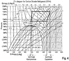
- a suitable cooling medium for this purpose is, for example, carbon dioxide (CO 2 ) with a critical temperature of 31.0 °C and a critical pressure of 73.8 bar. That is, the cooling circuit 38 must be designed to withstand such high pressures above the critical pressure.
- the super-critical mode of operation is advantageous because of the high density of the cooling medium in this state with correspondingly high heat transfer capacity and yet high fluidity within the line system of the cooling circuit 38.
- the expansion engine 42 powers the compressor pump 46.
- This is preferably achieved as the expansion engine 42 and the compressor pump 46 are mechanically coupled to each other, preferably via a common shaft, and if necessary with a transmission gearing in between.
- other variants are possible as well, for example via generation of electrical energy with the help of an electrical generator 48. The generated electricity would then drive the motor of the compressor pump 46. If necessary, temporary storage of the electrical energy can take place in suitable storage units like accumulators.
- an additional heat exchanger 50 is switched into the cooling circuit downstream to the first heat exchanger 40 and upstream 38 to the expansion engine 42.
- the heat exchanger 50 is connected to the hot part of the exhaust line 10 between the recombiner unit 14 and the steam condenser 24 such that a branch stream of the hot exhaust stream serves as a heating medium.
- a dedicated throttle valve 52 in the exhaust line 10 and/or a filter unit 22 (see FIG. 1 ) and/or another device like a steam turbine 66 (see FIG. 3 ) acting as a throttle allows for back-feeding of the branch stream into the main exhaust stream before the steam condenser 24 without active driving means.
- the additional heat exchanger 50 acts as recuperative superheater for the cooling medium circulating in the cooling circuit 38 before it enters the expansion engine 42.
- the yield of the expansion engine 42 is increased, albeit with the potential drawback of introducing additional heat into the cooling circuit 38.
- a vortex cooler 54 is installed downstream the compressor pump 46 in order to further cool down the cooling medium before it re-enters the first heat exchanger 40 within the primary heat source.
- a vortex cooler 54 or vortex tube is a mechanical device without moving parts that separates a fluid stream into hot and cold branch streams by virtue of a vortex flow.
- the cold stream then enters the first heat exchanger 40 via cold fluid line 56, and the hot branch stream is re-injected into the main cooling loop just before or at the superheater 50 via hot fluid line 58. It has been found that in this way the above mentioned drawback can be compensated for or eliminated and the overall cooling efficiency of the system be improved.
- the expansion engine 42 also powers a blower 64 which is directed to the second heat exchanger 44 (aka air cooler) in order to improve its cooling efficiency.
- a blower 64 which is directed to the second heat exchanger 44 (aka air cooler) in order to improve its cooling efficiency. This can either be achieved by a mechanical coupling or indirectly via electrical energy generated by the generator 48, as indicated in the figures.
- the expansion engine 42 may also power, at least partially, the backfeed compressor 32 and/or the backfeed pump 36.
- the variant of the containment protection system shown in FIG. 3 differs from the one shown in FIG. 1 in that there is a steam turbine 66 switched into the exhaust line 10 between the recombiner unit 14 and the steam condenser 24.
- the steam turbine 66 converts a portion of the heat energy contained in the exhaust stream into mechanical work (approximately isentropic expansion) in order to drive, at least partially, the backfeed compressor 32 and/or the backfeed pump 36. This is achieved, for example, directly via mechanical coupling of the steam turbine 66 with the backfeed compressor 32 and/or the backfeed pump 36 and/or indirectly via generation of electrical energy by means of an electrical generator 68. It is also possible to have a turbine-compressor-generator unit on a single shaft. If necessary, temporary storage of the electrical energy can take place in suitable storage units like accumulators.
- the mechanical and/or electrical power generated by the steam turbine 66 can be used to drive, at least partially, the compressor pump 46 and/or the blower 64 of the cooling circuit 38.
- the available excess energy will depend on the hydrogen portion contained in the exhaust stream and on the necessary power for the backfeed compressor 32, which in turn depends on the pressure difference between containment 6 and steam condenser 24 during vent operation.
- the feeding line 80 for the superheater 50 is attached to the exhaust line 10 upstream of the steam turbine 66, while the return line 82 is attached downstream.
- the vortex cooler 54 known from FIG. 2 can of course also be used in the embodiment according to FIG. 3 in the same way.
- the whole containment protection system 8 or parts of it can be installed inside the containment 6.
- the parts of the containment protection system 8 which are directed at depressurization and cooling are also known as the depressurization and cooling system 90.
- the nuclear power plant can be of any known type, such as BWR, PWR, WER, HWR, HTR.
Landscapes
- Engineering & Computer Science (AREA)
- Physics & Mathematics (AREA)
- General Engineering & Computer Science (AREA)
- Plasma & Fusion (AREA)
- High Energy & Nuclear Physics (AREA)
- Mechanical Engineering (AREA)
- Thermal Sciences (AREA)
- Structure Of Emergency Protection For Nuclear Reactors (AREA)
- Engine Equipment That Uses Special Cycles (AREA)
Claims (16)
- Druckablass- und Kühlsystem (90) für Dampf und/oder kondensierbare Gase, die sich in der Atmosphäre im Inneren eines Sicherheitsbehälters (6) befinden, umfassend• einen Dampfkondensator (24) mit∘ einem durch eine Abgasleitung (10) mit dem Sicherheitsbehälter (6) verbundenen einlassseitigen Anschluss,∘ einem durch eine Rückspeiseleitung (30) mit dem Sicherheitsbehälter (6) verbundenen auslassseitigen Anschluss,∘ wobei diese Rückspeiseleitung einen Rückspeisekompressor (32) umfasst,• ein Rückkühlsystem zum Rückkühlen des Dampfkondensators (24),
bei dem das Rückkühlsystem ein thermodynamisches Zyklussystem eines Arbeitsfluids mit geschlossenem Arbeitsfluidkreislauf umfasst, bei dem der Dampfkondensator (24) eine Wärmequelle ist, bei dem das Rückkühlsystem entlang des geschlossenen Arbeitsfluidkreislaufs Folgendes umfasst:• einen thermisch mit dem Dampfkondensator (24) gekoppelten ersten Wärmetauscher (40),• eine mit dem ersten Wärmetauscher (40) fluidisch verbundene Expansionsmaschine (42),• einen mit der Expansionsmaschine (42) fluidisch verbundenen zweiten Wärmetauscher (44),• eine fluidisch dem zweiten Wärmetauscher (44) nachgeschaltete und dem ersten Wärmetauscher (40) vorgeschaltete Kompressorpumpe (46),
dadurch gekennzeichnet, dass die Expansionsmaschine (42) die Kompressorpumpe (46) mit Energie versorgt und ein Überhitzer (50) dem ersten Wärmetauscher (40) nachgeschaltet und der Expansionsmaschine (42) vorgeschaltet ist, wobei der Überhitzer (50) thermisch so mit der Abgasleitung (10) gekoppelt ist, dass er durch den Abgasstrom aufgeheizt wird. - Druckablass- und Kühlsystem (90) gemäß Anspruch 1, bei dem das Rückkühlsystem einen fluidisch der Kompressorpumpe (46) nachgeschalteten und dem ersten Wärmetauscher (40) vorgeschalteten Wirbelkühler (54) umfasst.
- Druckablass- und Kühlsystem (90) gemäß Anspruch 2, bei dem der Wirbelkühler (54) einen Heißfluid-Auslass hat, der fluidisch in einem Bereich des Rückkühlsystems dem ersten Wärmetauscher (40) nachgeschaltet und der Expansionsmaschine (42) vorgeschaltet ist, und vorzugsweise dem Überhitzer (50) vorgeschaltet oder mit dem Überhitzer (50) verbunden ist.
- Druckablass- und Kühlsystem (90) gemäß einem der vorhergehenden Ansprüche, bei dem die Abgasleitung (10) eine Rekombiniereinheit (14) umfasst, die dem Dampfkondensator (24) vorgeschaltet ist.
- Sicherheitsbehälter-Schutzsystem (8) für eine Kernkraftanlage (2) mit einem Sicherheitsbehälter (6), umfassend• eine Abgasleitung (10) für einen mit dem Sicherheitsbehälter (6) verbundenen Abgasstrom der Sicherheitsbehälteratmosphäre, mit einem in die Abgasleitung (10) geschalteten Dampfkondensator (24),• eine Rückspeiseleitung (30) für den gasförmigen Teil des vom Dampfkondensator (24) zum Sicherheitsbehälter (6) führenden Abgasstroms der Sicherheitsbehälteratmosphäre, mit einem in die Rückspeiseleitung (30) geschalteten Rückspeisekompressor (32),• einen Kühlkreislauf (38) zum Rückkühlen des Dampfkondensators (24),
wobei der Kühlkreislauf ein thermodynamisches Zyklussystem eines Arbeitsfluids mit geschlossenem Arbeitsfluidkreislauf umfasst, bei dem der Dampfkondensator (24) eine Wärmequelle ist, bei dem der Kühlkreislauf (38) einen thermisch mit dem Dampfkondensator (24) gekoppelten ersten Wärmetauscher (40) umfasst, und ferner umfassend eine mit dem ersten Wärmetauscher (40) fluidisch verbundene Expansionsmaschine (42), eine Kompressorpumpe (46) und einen thermisch mit einer Wärmesenke gekoppelten und mit der Expansionsmaschine (42) fluidisch verbundenen zweiten Wärmetauscher (44), bei dem die Kompressorpumpe (46) fluidisch dem zweiten Wärmetauscher (44) nachgeschaltet und dem ersten Wärmetauscher (40) vorgeschaltet ist, dadurch gekennzeichnet, dass die Expansionsmaschine (42) die Kompressorpumpe (46) mit Energie versorgt und dass sich im Kühlkreislauf (38) zwischen dem ersten Wärmetauscher (40) und der Expansionsmaschine (42) ein Überhitzer (50) befindet, wobei der Überhitzer (50) thermisch so mit der Abgasleitung (10) gekoppelt ist, dass er durch den Abgasstrom der Sicherheitsbehälteratmosphäre aufgeheizt wird. - Sicherheitsbehälter-Schutzsystem (8) gemäß Anspruch 5, umfassend einen Wirbelkühler (54) im Kühlkreislauf (38) zwischen der Kompressorpumpe (46) und dem ersten Wärmetauscher (40).
- Sicherheitsbehälter-Schutzsystem (8) gemäß Anspruch 6, bei dem der Wirbelkühler (54) einen Heißfluid-Auslass hat, der in einem Bereich zwischen dem ersten Wärmetauscher (40) und der Expansionsmaschine (42), vorzugsweise dem Überhitzer (50) vorgeschaltet oder mit dem Überhitzer (50) verbunden, fluidisch mit dem Kühlkreislauf (38) verbunden ist.
- Sicherheitsbehälter-Schutzsystem (8) gemäß einem der Ansprüche 5 bis 7, bei dem die Rekombiniereinheit (14) dem Dampfkondensator (24) vorgeschaltet in die Abgasleitung (10) geschaltet ist.
- Sicherheitsbehälter-Schutzsystem (8) gemäß einem der Ansprüche 5 bis 8, bei dem der zweite Wärmetauscher (44) als Luftkühler ausgeführt ist.
- Sicherheitsbehälter-Schutzsystem (8) gemäß einem der Ansprüche 5 bis 9, bei dem der Kühlkreislauf (38) für die Zirkulation eines Kühlmediums in einem superkritischen Zustand ausgelegt ist.
- Sicherheitsbehälter-Schutzsystem (8) gemäß einem der Ansprüche 5 bis 10, bei dem das Kühlmedium eine Siedetemperatur unter 100°C, vorzugsweise unter 80°C, hat.
- Sicherheitsbehälter-Schutzsystem (8) gemäß einem der Ansprüche 5 bis 11, bei dem das Kühlmedium Kohlendioxid ist.
- Sicherheitsbehälter-Schutzsystem (8) gemäß einem der Ansprüche 5 bis 12, bei dem die Expansionsmaschine (42) und die Kompressorpumpe (46) mechanisch, vorzugsweise über eine gemeinsame Welle, miteinander gekoppelt sind.
- Sicherheitsbehälter-Schutzsystem (8) gemäß einem der Ansprüche 5 bis 13, bei dem die Expansionsmaschine (42) auch ein Gebläse (64) mit Energie versorgt, wobei das Gebläse (64) auf den zweiten Wärmetauscher (44) gerichtet ist.
- Sicherheitsbehälter-Schutzsystem (8) gemäß einem der Ansprüche 5 bis 14, bei dem die Expansionsmaschine (42), zumindest teilweise, auch den Rückspeisekompressor (32) mit Energie versorgt.
- Kernkraftanlage (2) mit einem Sicherheitsbehälter (6) und einem Druckablass- und Kühlsystem (90) gemäß einem der Ansprüche 1 bis 4 oder einem Sicherheitsbehälter-Schutzsystem (8) gemäß einem der Ansprüche 5 bis 15.
Applications Claiming Priority (1)
| Application Number | Priority Date | Filing Date | Title |
|---|---|---|---|
| PCT/EP2015/076106 WO2017080580A1 (en) | 2015-11-09 | 2015-11-09 | Depressurization and cooling system for a containment of a nuclear power plant |
Publications (2)
| Publication Number | Publication Date |
|---|---|
| EP3374719A1 EP3374719A1 (de) | 2018-09-19 |
| EP3374719B1 true EP3374719B1 (de) | 2019-08-14 |
Family
ID=54754594
Family Applications (1)
| Application Number | Title | Priority Date | Filing Date |
|---|---|---|---|
| EP15802000.8A Not-in-force EP3374719B1 (de) | 2015-11-09 | 2015-11-09 | Druckablass- und kühlsystem für einen sicherheitsbehälter einer kernkraftanlage |
Country Status (8)
| Country | Link |
|---|---|
| US (1) | US11107593B2 (de) |
| EP (1) | EP3374719B1 (de) |
| KR (1) | KR102479196B1 (de) |
| CN (1) | CN108431535B (de) |
| CA (1) | CA3004353A1 (de) |
| RU (1) | RU2696836C1 (de) |
| UA (1) | UA121999C2 (de) |
| WO (1) | WO2017080580A1 (de) |
Families Citing this family (8)
| Publication number | Priority date | Publication date | Assignee | Title |
|---|---|---|---|---|
| KR101988265B1 (ko) * | 2017-05-24 | 2019-06-12 | 한국원자력연구원 | 원자로용기 내 냉각 및 발전 시스템 |
| CN107845434B (zh) * | 2017-10-27 | 2022-03-04 | 中国核电工程有限公司 | 一种非能动反应堆堆芯辅助冷却系统 |
| US11355255B2 (en) * | 2019-01-22 | 2022-06-07 | Korea Atomic Energy Research Institute | System and method for reducing atmospheric release of radioactive materials caused by severe accident |
| JP7453062B2 (ja) * | 2020-05-29 | 2024-03-19 | 日立Geニュークリア・エナジー株式会社 | 原子力発電プラント |
| JP7482019B2 (ja) | 2020-12-24 | 2024-05-13 | 日立Geニュークリア・エナジー株式会社 | 原子炉格納容器ベントシステム |
| CN114121309B (zh) * | 2021-11-26 | 2024-08-20 | 中国核动力研究设计院 | 一种基于全陶瓷弥散微封装燃料和碳化硅包壳的反应堆 |
| KR102627702B1 (ko) * | 2022-03-28 | 2024-01-19 | 현대로템 주식회사 | 축냉열교환기를 적용한 발열체용 열관리시스템 |
| CN115831404A (zh) * | 2022-10-28 | 2023-03-21 | 中核燕龙科技有限公司 | 非能动加压池式反应堆 |
Citations (2)
| Publication number | Priority date | Publication date | Assignee | Title |
|---|---|---|---|---|
| US3085056A (en) * | 1955-11-30 | 1963-04-09 | Babcock & Wilcox Co | Method and apparatus for generating and superheating steam from nuclear energy |
| GB1468308A (en) * | 1975-01-08 | 1977-03-23 | Orlov V | Nuclear power plant |
Family Cites Families (14)
| Publication number | Priority date | Publication date | Assignee | Title |
|---|---|---|---|---|
| US4513573A (en) * | 1972-05-12 | 1985-04-30 | Funk Harald F | System for treating and recovering energy from exhaust gases |
| CH629022A5 (de) * | 1978-06-13 | 1982-03-31 | Sulzer Ag | Kernreaktoranlage zum erzeugen von prozesswaerme. |
| RU2127815C1 (ru) * | 1997-01-27 | 1999-03-20 | Исачкин Анатолий Федорович | Тепловая силовая установка с холодильником |
| EP1332789B1 (de) * | 2002-02-04 | 2008-04-09 | AREVA NP GmbH | Verfahren zur katalytischen Oxidation eines Gases sowie Rekombinationseinrichtung zur Durchführung des Verfahrens und System mit derartigen Rekombinationseinrichtung |
| DE102011107284A1 (de) * | 2011-07-06 | 2013-01-10 | Rwe Technology Gmbh | Einrichtung zur Notkühlung einer Anlage für exotherme Prozesse |
| JP5763495B2 (ja) * | 2011-10-03 | 2015-08-12 | 株式会社東芝 | バイナリー発電システム |
| US8783035B2 (en) * | 2011-11-15 | 2014-07-22 | Shell Oil Company | System and process for generation of electrical power |
| DE102012213489A1 (de) * | 2012-07-31 | 2014-02-06 | Areva Gmbh | Wärmeabfuhrsystem für eine kerntechnische Anlage |
| DE102012213614B3 (de) * | 2012-08-01 | 2014-04-03 | Areva Gmbh | Containment-Schutzsystem für eine kerntechnische Anlage und zugehöriges Betriebsverfahren |
| JP6064575B2 (ja) * | 2012-12-17 | 2017-01-25 | いすゞ自動車株式会社 | 内燃機関の排熱回収装置と内燃機関の排熱回収方法 |
| FR3002274B1 (fr) * | 2013-02-15 | 2015-02-20 | Commissariat Energie Atomique | Installation de production d'electricite comportant un dispositif de production de vapeur d'eau de hauteur reduite, application aux reacteurs rep et reb |
| EP3008298B1 (de) * | 2013-09-25 | 2020-11-18 | Siemens Aktiengesellschaft | Anordnung und verfahren zur nutzung von abwärme |
| CN104464845A (zh) * | 2014-12-03 | 2015-03-25 | 中广核工程有限公司 | 核电站安全壳热量导出系统 |
| CN204614459U (zh) * | 2014-12-29 | 2015-09-02 | 国核华清(北京)核电技术研发中心有限公司 | 一种非能动核电站泄压冷凝换热系统 |
-
2015
- 2015-11-09 EP EP15802000.8A patent/EP3374719B1/de not_active Not-in-force
- 2015-11-09 CA CA3004353A patent/CA3004353A1/en not_active Abandoned
- 2015-11-09 KR KR1020187014792A patent/KR102479196B1/ko active Active
- 2015-11-09 RU RU2018121251A patent/RU2696836C1/ru active
- 2015-11-09 WO PCT/EP2015/076106 patent/WO2017080580A1/en not_active Ceased
- 2015-11-09 CN CN201580084417.3A patent/CN108431535B/zh not_active Expired - Fee Related
- 2015-11-09 UA UAA201804994A patent/UA121999C2/uk unknown
-
2018
- 2018-05-08 US US15/974,065 patent/US11107593B2/en not_active Expired - Fee Related
Patent Citations (2)
| Publication number | Priority date | Publication date | Assignee | Title |
|---|---|---|---|---|
| US3085056A (en) * | 1955-11-30 | 1963-04-09 | Babcock & Wilcox Co | Method and apparatus for generating and superheating steam from nuclear energy |
| GB1468308A (en) * | 1975-01-08 | 1977-03-23 | Orlov V | Nuclear power plant |
Also Published As
| Publication number | Publication date |
|---|---|
| US20180261340A1 (en) | 2018-09-13 |
| US11107593B2 (en) | 2021-08-31 |
| RU2696836C1 (ru) | 2019-08-06 |
| KR20180070692A (ko) | 2018-06-26 |
| KR102479196B1 (ko) | 2022-12-19 |
| CN108431535A (zh) | 2018-08-21 |
| EP3374719A1 (de) | 2018-09-19 |
| WO2017080580A1 (en) | 2017-05-18 |
| CA3004353A1 (en) | 2017-05-18 |
| UA121999C2 (uk) | 2020-08-25 |
| CN108431535B (zh) | 2020-02-14 |
Similar Documents
| Publication | Publication Date | Title |
|---|---|---|
| EP3374719B1 (de) | Druckablass- und kühlsystem für einen sicherheitsbehälter einer kernkraftanlage | |
| US7328581B2 (en) | Low emission thermal plant | |
| KR101454089B1 (ko) | 고온 가스 냉각로 증기 발전 시스템 및 방법 | |
| US8045671B2 (en) | Injection system and associated operating method | |
| RU2542655C2 (ru) | Байпас турбины | |
| US4051892A (en) | Heat dissipation system | |
| ES2708352T3 (es) | Sistema y método para generación de energía de alta eficiencia utilizando un fluido de trabajo de circulación de dióxido de carbono | |
| CN204480678U (zh) | 一种核电站非能动余热排出系统 | |
| US20120294407A1 (en) | Nuclear Power Plant, Fuel Pool Water Cooling Facility and Method Thereof | |
| CN104541331A (zh) | 用于核技术设施的反应堆外壳保护系统及相关操作方法 | |
| WO2007024569A2 (en) | Hybrid integrated energy production process | |
| RU2142171C1 (ru) | Способ и устройство для получения инертизирующего газа | |
| CN105810256A (zh) | 一种核电站非能动余热排出系统 | |
| US20170098483A1 (en) | Heat exchange system and nuclear reactor system | |
| KR20180108168A (ko) | 모듈 원전 | |
| KR101382256B1 (ko) | 가압경수로형 원자력발전소의 피동형 보조냉각수 공급시스템 | |
| KR101629657B1 (ko) | 초소형 발전 모듈 | |
| TW201312586A (zh) | 放熱製程工廠緊急冷卻裝置 | |
| EP2601394B1 (de) | Gasturbine mit verbesserter energierückgewinnung | |
| JP2019200192A (ja) | 原子力発電所のコンテインメントのための減圧および冷却システム | |
| KR20160097157A (ko) | 초소형 발전 모듈 | |
| Thimsen et al. | Challenges in designing fuel-fired sCO2 heaters for closed sCO2 Brayton cycle power plants | |
| JP2021189042A (ja) | 原子力発電プラント | |
| RU2070347C1 (ru) | Система аварийного расхолаживания водоохлаждаемого реактора и среды под защитной оболочкой | |
| CZ20013331A3 (cs) | Paroplynová turbína s transformátorem páry |
Legal Events
| Date | Code | Title | Description |
|---|---|---|---|
| STAA | Information on the status of an ep patent application or granted ep patent |
Free format text: STATUS: THE INTERNATIONAL PUBLICATION HAS BEEN MADE |
|
| PUAI | Public reference made under article 153(3) epc to a published international application that has entered the european phase |
Free format text: ORIGINAL CODE: 0009012 |
|
| STAA | Information on the status of an ep patent application or granted ep patent |
Free format text: STATUS: REQUEST FOR EXAMINATION WAS MADE |
|
| 17P | Request for examination filed |
Effective date: 20180517 |
|
| AK | Designated contracting states |
Kind code of ref document: A1 Designated state(s): AL AT BE BG CH CY CZ DE DK EE ES FI FR GB GR HR HU IE IS IT LI LT LU LV MC MK MT NL NO PL PT RO RS SE SI SK SM TR |
|
| AX | Request for extension of the european patent |
Extension state: BA ME |
|
| DAV | Request for validation of the european patent (deleted) | ||
| DAX | Request for extension of the european patent (deleted) | ||
| REG | Reference to a national code |
Ref country code: DE Ref legal event code: R079 Ref document number: 602015035939 Country of ref document: DE Free format text: PREVIOUS MAIN CLASS: F28D0021000000 Ipc: F28D0001000000 |
|
| GRAP | Despatch of communication of intention to grant a patent |
Free format text: ORIGINAL CODE: EPIDOSNIGR1 |
|
| STAA | Information on the status of an ep patent application or granted ep patent |
Free format text: STATUS: GRANT OF PATENT IS INTENDED |
|
| RIC1 | Information provided on ipc code assigned before grant |
Ipc: F28D 1/00 20060101AFI20190402BHEP Ipc: F28B 9/06 20060101ALI20190402BHEP Ipc: G21C 15/18 20060101ALI20190402BHEP Ipc: F28D 21/00 20060101ALI20190402BHEP Ipc: F25B 9/04 20060101ALN20190402BHEP Ipc: G21C 9/012 20060101ALI20190402BHEP |
|
| INTG | Intention to grant announced |
Effective date: 20190423 |
|
| GRAS | Grant fee paid |
Free format text: ORIGINAL CODE: EPIDOSNIGR3 |
|
| GRAA | (expected) grant |
Free format text: ORIGINAL CODE: 0009210 |
|
| STAA | Information on the status of an ep patent application or granted ep patent |
Free format text: STATUS: THE PATENT HAS BEEN GRANTED |
|
| AK | Designated contracting states |
Kind code of ref document: B1 Designated state(s): AL AT BE BG CH CY CZ DE DK EE ES FI FR GB GR HR HU IE IS IT LI LT LU LV MC MK MT NL NO PL PT RO RS SE SI SK SM TR |
|
| REG | Reference to a national code |
Ref country code: GB Ref legal event code: FG4D |
|
| REG | Reference to a national code |
Ref country code: CH Ref legal event code: EP Ref country code: AT Ref legal event code: REF Ref document number: 1167533 Country of ref document: AT Kind code of ref document: T Effective date: 20190815 |
|
| REG | Reference to a national code |
Ref country code: IE Ref legal event code: FG4D |
|
| REG | Reference to a national code |
Ref country code: DE Ref legal event code: R096 Ref document number: 602015035939 Country of ref document: DE |
|
| REG | Reference to a national code |
Ref country code: NL Ref legal event code: MP Effective date: 20190814 |
|
| REG | Reference to a national code |
Ref country code: LT Ref legal event code: MG4D |
|
| PG25 | Lapsed in a contracting state [announced via postgrant information from national office to epo] |
Ref country code: FI Free format text: LAPSE BECAUSE OF FAILURE TO SUBMIT A TRANSLATION OF THE DESCRIPTION OR TO PAY THE FEE WITHIN THE PRESCRIBED TIME-LIMIT Effective date: 20190814 Ref country code: LT Free format text: LAPSE BECAUSE OF FAILURE TO SUBMIT A TRANSLATION OF THE DESCRIPTION OR TO PAY THE FEE WITHIN THE PRESCRIBED TIME-LIMIT Effective date: 20190814 Ref country code: NL Free format text: LAPSE BECAUSE OF FAILURE TO SUBMIT A TRANSLATION OF THE DESCRIPTION OR TO PAY THE FEE WITHIN THE PRESCRIBED TIME-LIMIT Effective date: 20190814 Ref country code: BG Free format text: LAPSE BECAUSE OF FAILURE TO SUBMIT A TRANSLATION OF THE DESCRIPTION OR TO PAY THE FEE WITHIN THE PRESCRIBED TIME-LIMIT Effective date: 20191114 Ref country code: NO Free format text: LAPSE BECAUSE OF FAILURE TO SUBMIT A TRANSLATION OF THE DESCRIPTION OR TO PAY THE FEE WITHIN THE PRESCRIBED TIME-LIMIT Effective date: 20191114 Ref country code: PT Free format text: LAPSE BECAUSE OF FAILURE TO SUBMIT A TRANSLATION OF THE DESCRIPTION OR TO PAY THE FEE WITHIN THE PRESCRIBED TIME-LIMIT Effective date: 20191216 Ref country code: HR Free format text: LAPSE BECAUSE OF FAILURE TO SUBMIT A TRANSLATION OF THE DESCRIPTION OR TO PAY THE FEE WITHIN THE PRESCRIBED TIME-LIMIT Effective date: 20190814 Ref country code: SE Free format text: LAPSE BECAUSE OF FAILURE TO SUBMIT A TRANSLATION OF THE DESCRIPTION OR TO PAY THE FEE WITHIN THE PRESCRIBED TIME-LIMIT Effective date: 20190814 |
|
| REG | Reference to a national code |
Ref country code: AT Ref legal event code: MK05 Ref document number: 1167533 Country of ref document: AT Kind code of ref document: T Effective date: 20190814 |
|
| PG25 | Lapsed in a contracting state [announced via postgrant information from national office to epo] |
Ref country code: RS Free format text: LAPSE BECAUSE OF FAILURE TO SUBMIT A TRANSLATION OF THE DESCRIPTION OR TO PAY THE FEE WITHIN THE PRESCRIBED TIME-LIMIT Effective date: 20190814 Ref country code: IS Free format text: LAPSE BECAUSE OF FAILURE TO SUBMIT A TRANSLATION OF THE DESCRIPTION OR TO PAY THE FEE WITHIN THE PRESCRIBED TIME-LIMIT Effective date: 20191214 Ref country code: GR Free format text: LAPSE BECAUSE OF FAILURE TO SUBMIT A TRANSLATION OF THE DESCRIPTION OR TO PAY THE FEE WITHIN THE PRESCRIBED TIME-LIMIT Effective date: 20191115 Ref country code: LV Free format text: LAPSE BECAUSE OF FAILURE TO SUBMIT A TRANSLATION OF THE DESCRIPTION OR TO PAY THE FEE WITHIN THE PRESCRIBED TIME-LIMIT Effective date: 20190814 Ref country code: ES Free format text: LAPSE BECAUSE OF FAILURE TO SUBMIT A TRANSLATION OF THE DESCRIPTION OR TO PAY THE FEE WITHIN THE PRESCRIBED TIME-LIMIT Effective date: 20190814 Ref country code: AL Free format text: LAPSE BECAUSE OF FAILURE TO SUBMIT A TRANSLATION OF THE DESCRIPTION OR TO PAY THE FEE WITHIN THE PRESCRIBED TIME-LIMIT Effective date: 20190814 |
|
| PG25 | Lapsed in a contracting state [announced via postgrant information from national office to epo] |
Ref country code: TR Free format text: LAPSE BECAUSE OF FAILURE TO SUBMIT A TRANSLATION OF THE DESCRIPTION OR TO PAY THE FEE WITHIN THE PRESCRIBED TIME-LIMIT Effective date: 20190814 |
|
| PG25 | Lapsed in a contracting state [announced via postgrant information from national office to epo] |
Ref country code: EE Free format text: LAPSE BECAUSE OF FAILURE TO SUBMIT A TRANSLATION OF THE DESCRIPTION OR TO PAY THE FEE WITHIN THE PRESCRIBED TIME-LIMIT Effective date: 20190814 Ref country code: DK Free format text: LAPSE BECAUSE OF FAILURE TO SUBMIT A TRANSLATION OF THE DESCRIPTION OR TO PAY THE FEE WITHIN THE PRESCRIBED TIME-LIMIT Effective date: 20190814 Ref country code: AT Free format text: LAPSE BECAUSE OF FAILURE TO SUBMIT A TRANSLATION OF THE DESCRIPTION OR TO PAY THE FEE WITHIN THE PRESCRIBED TIME-LIMIT Effective date: 20190814 Ref country code: IT Free format text: LAPSE BECAUSE OF FAILURE TO SUBMIT A TRANSLATION OF THE DESCRIPTION OR TO PAY THE FEE WITHIN THE PRESCRIBED TIME-LIMIT Effective date: 20190814 Ref country code: RO Free format text: LAPSE BECAUSE OF FAILURE TO SUBMIT A TRANSLATION OF THE DESCRIPTION OR TO PAY THE FEE WITHIN THE PRESCRIBED TIME-LIMIT Effective date: 20190814 Ref country code: PL Free format text: LAPSE BECAUSE OF FAILURE TO SUBMIT A TRANSLATION OF THE DESCRIPTION OR TO PAY THE FEE WITHIN THE PRESCRIBED TIME-LIMIT Effective date: 20190814 |
|
| PG25 | Lapsed in a contracting state [announced via postgrant information from national office to epo] |
Ref country code: SK Free format text: LAPSE BECAUSE OF FAILURE TO SUBMIT A TRANSLATION OF THE DESCRIPTION OR TO PAY THE FEE WITHIN THE PRESCRIBED TIME-LIMIT Effective date: 20190814 Ref country code: CZ Free format text: LAPSE BECAUSE OF FAILURE TO SUBMIT A TRANSLATION OF THE DESCRIPTION OR TO PAY THE FEE WITHIN THE PRESCRIBED TIME-LIMIT Effective date: 20190814 Ref country code: IS Free format text: LAPSE BECAUSE OF FAILURE TO SUBMIT A TRANSLATION OF THE DESCRIPTION OR TO PAY THE FEE WITHIN THE PRESCRIBED TIME-LIMIT Effective date: 20200224 Ref country code: SM Free format text: LAPSE BECAUSE OF FAILURE TO SUBMIT A TRANSLATION OF THE DESCRIPTION OR TO PAY THE FEE WITHIN THE PRESCRIBED TIME-LIMIT Effective date: 20190814 |
|
| REG | Reference to a national code |
Ref country code: DE Ref legal event code: R097 Ref document number: 602015035939 Country of ref document: DE |
|
| REG | Reference to a national code |
Ref country code: CH Ref legal event code: PL |
|
| PLBE | No opposition filed within time limit |
Free format text: ORIGINAL CODE: 0009261 |
|
| STAA | Information on the status of an ep patent application or granted ep patent |
Free format text: STATUS: NO OPPOSITION FILED WITHIN TIME LIMIT |
|
| PG2D | Information on lapse in contracting state deleted |
Ref country code: IS |
|
| PG25 | Lapsed in a contracting state [announced via postgrant information from national office to epo] |
Ref country code: LI Free format text: LAPSE BECAUSE OF NON-PAYMENT OF DUE FEES Effective date: 20191130 Ref country code: MC Free format text: LAPSE BECAUSE OF FAILURE TO SUBMIT A TRANSLATION OF THE DESCRIPTION OR TO PAY THE FEE WITHIN THE PRESCRIBED TIME-LIMIT Effective date: 20190814 Ref country code: LU Free format text: LAPSE BECAUSE OF NON-PAYMENT OF DUE FEES Effective date: 20191109 Ref country code: CH Free format text: LAPSE BECAUSE OF NON-PAYMENT OF DUE FEES Effective date: 20191130 |
|
| 26N | No opposition filed |
Effective date: 20200603 |
|
| REG | Reference to a national code |
Ref country code: BE Ref legal event code: MM Effective date: 20191130 |
|
| PG25 | Lapsed in a contracting state [announced via postgrant information from national office to epo] |
Ref country code: SI Free format text: LAPSE BECAUSE OF FAILURE TO SUBMIT A TRANSLATION OF THE DESCRIPTION OR TO PAY THE FEE WITHIN THE PRESCRIBED TIME-LIMIT Effective date: 20190814 |
|
| PG25 | Lapsed in a contracting state [announced via postgrant information from national office to epo] |
Ref country code: IE Free format text: LAPSE BECAUSE OF NON-PAYMENT OF DUE FEES Effective date: 20191109 |
|
| PG25 | Lapsed in a contracting state [announced via postgrant information from national office to epo] |
Ref country code: BE Free format text: LAPSE BECAUSE OF NON-PAYMENT OF DUE FEES Effective date: 20191130 |
|
| PG25 | Lapsed in a contracting state [announced via postgrant information from national office to epo] |
Ref country code: CY Free format text: LAPSE BECAUSE OF FAILURE TO SUBMIT A TRANSLATION OF THE DESCRIPTION OR TO PAY THE FEE WITHIN THE PRESCRIBED TIME-LIMIT Effective date: 20190814 |
|
| PG25 | Lapsed in a contracting state [announced via postgrant information from national office to epo] |
Ref country code: HU Free format text: LAPSE BECAUSE OF FAILURE TO SUBMIT A TRANSLATION OF THE DESCRIPTION OR TO PAY THE FEE WITHIN THE PRESCRIBED TIME-LIMIT; INVALID AB INITIO Effective date: 20151109 Ref country code: MT Free format text: LAPSE BECAUSE OF FAILURE TO SUBMIT A TRANSLATION OF THE DESCRIPTION OR TO PAY THE FEE WITHIN THE PRESCRIBED TIME-LIMIT Effective date: 20190814 |
|
| PG25 | Lapsed in a contracting state [announced via postgrant information from national office to epo] |
Ref country code: MK Free format text: LAPSE BECAUSE OF FAILURE TO SUBMIT A TRANSLATION OF THE DESCRIPTION OR TO PAY THE FEE WITHIN THE PRESCRIBED TIME-LIMIT Effective date: 20190814 |
|
| PGFP | Annual fee paid to national office [announced via postgrant information from national office to epo] |
Ref country code: GB Payment date: 20221121 Year of fee payment: 8 Ref country code: FR Payment date: 20221122 Year of fee payment: 8 Ref country code: DE Payment date: 20221114 Year of fee payment: 8 |
|
| REG | Reference to a national code |
Ref country code: DE Ref legal event code: R119 Ref document number: 602015035939 Country of ref document: DE |
|
| GBPC | Gb: european patent ceased through non-payment of renewal fee |
Effective date: 20231109 |
|
| PG25 | Lapsed in a contracting state [announced via postgrant information from national office to epo] |
Ref country code: DE Free format text: LAPSE BECAUSE OF NON-PAYMENT OF DUE FEES Effective date: 20240601 |
|
| PG25 | Lapsed in a contracting state [announced via postgrant information from national office to epo] |
Ref country code: GB Free format text: LAPSE BECAUSE OF NON-PAYMENT OF DUE FEES Effective date: 20231109 |
|
| PG25 | Lapsed in a contracting state [announced via postgrant information from national office to epo] |
Ref country code: FR Free format text: LAPSE BECAUSE OF NON-PAYMENT OF DUE FEES Effective date: 20231130 |
|
| PG25 | Lapsed in a contracting state [announced via postgrant information from national office to epo] |
Ref country code: GB Free format text: LAPSE BECAUSE OF NON-PAYMENT OF DUE FEES Effective date: 20231109 Ref country code: FR Free format text: LAPSE BECAUSE OF NON-PAYMENT OF DUE FEES Effective date: 20231130 Ref country code: DE Free format text: LAPSE BECAUSE OF NON-PAYMENT OF DUE FEES Effective date: 20240601 |