EP3374699B1 - Method for controlling a centrifugal pump, and associated pump system - Google Patents
Method for controlling a centrifugal pump, and associated pump system Download PDFInfo
- Publication number
- EP3374699B1 EP3374699B1 EP16809630.3A EP16809630A EP3374699B1 EP 3374699 B1 EP3374699 B1 EP 3374699B1 EP 16809630 A EP16809630 A EP 16809630A EP 3374699 B1 EP3374699 B1 EP 3374699B1
- Authority
- EP
- European Patent Office
- Prior art keywords
- circuit
- pri
- consumer
- sec
- volume flow
- Prior art date
- Legal status (The legal status is an assumption and is not a legal conclusion. Google has not performed a legal analysis and makes no representation as to the accuracy of the status listed.)
- Active
Links
- 238000000034 method Methods 0.000 title claims description 50
- 238000012546 transfer Methods 0.000 claims description 116
- 238000010438 heat treatment Methods 0.000 claims description 83
- 239000002826 coolant Substances 0.000 claims description 35
- 238000001816 cooling Methods 0.000 claims description 28
- 238000011156 evaluation Methods 0.000 claims description 16
- 241000237519 Bivalvia Species 0.000 claims 1
- 235000020639 clam Nutrition 0.000 claims 1
- 230000001105 regulatory effect Effects 0.000 description 54
- 238000012937 correction Methods 0.000 description 22
- 238000004891 communication Methods 0.000 description 17
- 238000004364 calculation method Methods 0.000 description 14
- 238000005259 measurement Methods 0.000 description 14
- 238000005516 engineering process Methods 0.000 description 11
- 238000009529 body temperature measurement Methods 0.000 description 9
- 238000011144 upstream manufacturing Methods 0.000 description 9
- 108010032039 (rat secretin-27)-Gly-rhodamine Proteins 0.000 description 8
- 230000008901 benefit Effects 0.000 description 8
- 238000013461 design Methods 0.000 description 6
- 230000005540 biological transmission Effects 0.000 description 5
- 230000001419 dependent effect Effects 0.000 description 5
- 238000011161 development Methods 0.000 description 5
- 230000018109 developmental process Effects 0.000 description 5
- 239000007788 liquid Substances 0.000 description 3
- LYCAIKOWRPUZTN-UHFFFAOYSA-N Ethylene glycol Chemical compound OCCO LYCAIKOWRPUZTN-UHFFFAOYSA-N 0.000 description 2
- 230000008859 change Effects 0.000 description 2
- 238000012423 maintenance Methods 0.000 description 2
- 230000008569 process Effects 0.000 description 2
- 238000012935 Averaging Methods 0.000 description 1
- 230000006978 adaptation Effects 0.000 description 1
- TZCXTZWJZNENPQ-UHFFFAOYSA-L barium sulfate Chemical compound [Ba+2].[O-]S([O-])(=O)=O TZCXTZWJZNENPQ-UHFFFAOYSA-L 0.000 description 1
- 238000010276 construction Methods 0.000 description 1
- 230000008878 coupling Effects 0.000 description 1
- 238000010168 coupling process Methods 0.000 description 1
- 238000005859 coupling reaction Methods 0.000 description 1
- 238000001514 detection method Methods 0.000 description 1
- 239000012530 fluid Substances 0.000 description 1
- WGCNASOHLSPBMP-UHFFFAOYSA-N hydroxyacetaldehyde Natural products OCC=O WGCNASOHLSPBMP-UHFFFAOYSA-N 0.000 description 1
- 238000009434 installation Methods 0.000 description 1
- 238000007620 mathematical function Methods 0.000 description 1
- 239000000203 mixture Substances 0.000 description 1
- 238000012545 processing Methods 0.000 description 1
- 239000000126 substance Substances 0.000 description 1
- XLYOFNOQVPJJNP-UHFFFAOYSA-N water Substances O XLYOFNOQVPJJNP-UHFFFAOYSA-N 0.000 description 1
Images


Classifications
-
- F—MECHANICAL ENGINEERING; LIGHTING; HEATING; WEAPONS; BLASTING
- F24—HEATING; RANGES; VENTILATING
- F24D—DOMESTIC- OR SPACE-HEATING SYSTEMS, e.g. CENTRAL HEATING SYSTEMS; DOMESTIC HOT-WATER SUPPLY SYSTEMS; ELEMENTS OR COMPONENTS THEREFOR
- F24D19/00—Details
- F24D19/10—Arrangement or mounting of control or safety devices
- F24D19/1006—Arrangement or mounting of control or safety devices for water heating systems
- F24D19/1009—Arrangement or mounting of control or safety devices for water heating systems for central heating
- F24D19/1012—Arrangement or mounting of control or safety devices for water heating systems for central heating by regulating the speed of a pump
-
- F—MECHANICAL ENGINEERING; LIGHTING; HEATING; WEAPONS; BLASTING
- F04—POSITIVE - DISPLACEMENT MACHINES FOR LIQUIDS; PUMPS FOR LIQUIDS OR ELASTIC FLUIDS
- F04D—NON-POSITIVE-DISPLACEMENT PUMPS
- F04D13/00—Pumping installations or systems
- F04D13/12—Combinations of two or more pumps
-
- F—MECHANICAL ENGINEERING; LIGHTING; HEATING; WEAPONS; BLASTING
- F04—POSITIVE - DISPLACEMENT MACHINES FOR LIQUIDS; PUMPS FOR LIQUIDS OR ELASTIC FLUIDS
- F04D—NON-POSITIVE-DISPLACEMENT PUMPS
- F04D15/00—Control, e.g. regulation, of pumps, pumping installations or systems
- F04D15/0066—Control, e.g. regulation, of pumps, pumping installations or systems by changing the speed, e.g. of the driving engine
-
- G—PHYSICS
- G05—CONTROLLING; REGULATING
- G05B—CONTROL OR REGULATING SYSTEMS IN GENERAL; FUNCTIONAL ELEMENTS OF SUCH SYSTEMS; MONITORING OR TESTING ARRANGEMENTS FOR SUCH SYSTEMS OR ELEMENTS
- G05B13/00—Adaptive control systems, i.e. systems automatically adjusting themselves to have a performance which is optimum according to some preassigned criterion
-
- G—PHYSICS
- G05—CONTROLLING; REGULATING
- G05D—SYSTEMS FOR CONTROLLING OR REGULATING NON-ELECTRIC VARIABLES
- G05D11/00—Control of flow ratio
- G05D11/003—Control of flow ratio using interconnected flow control elements
-
- G—PHYSICS
- G05—CONTROLLING; REGULATING
- G05D—SYSTEMS FOR CONTROLLING OR REGULATING NON-ELECTRIC VARIABLES
- G05D11/00—Control of flow ratio
- G05D11/008—Control of flow ratio involving a fluid operating a pump motor
-
- G—PHYSICS
- G05—CONTROLLING; REGULATING
- G05D—SYSTEMS FOR CONTROLLING OR REGULATING NON-ELECTRIC VARIABLES
- G05D7/00—Control of flow
- G05D7/01—Control of flow without auxiliary power
- G05D7/0126—Control of flow without auxiliary power the sensing element being a piston or plunger associated with one or more springs
- G05D7/0133—Control of flow without auxiliary power the sensing element being a piston or plunger associated with one or more springs within the flow-path
-
- F—MECHANICAL ENGINEERING; LIGHTING; HEATING; WEAPONS; BLASTING
- F24—HEATING; RANGES; VENTILATING
- F24D—DOMESTIC- OR SPACE-HEATING SYSTEMS, e.g. CENTRAL HEATING SYSTEMS; DOMESTIC HOT-WATER SUPPLY SYSTEMS; ELEMENTS OR COMPONENTS THEREFOR
- F24D2220/00—Components of central heating installations excluding heat sources
- F24D2220/02—Fluid distribution means
- F24D2220/0207—Pumps
-
- G—PHYSICS
- G05—CONTROLLING; REGULATING
- G05B—CONTROL OR REGULATING SYSTEMS IN GENERAL; FUNCTIONAL ELEMENTS OF SUCH SYSTEMS; MONITORING OR TESTING ARRANGEMENTS FOR SUCH SYSTEMS OR ELEMENTS
- G05B13/00—Adaptive control systems, i.e. systems automatically adjusting themselves to have a performance which is optimum according to some preassigned criterion
- G05B13/02—Adaptive control systems, i.e. systems automatically adjusting themselves to have a performance which is optimum according to some preassigned criterion electric
- G05B13/04—Adaptive control systems, i.e. systems automatically adjusting themselves to have a performance which is optimum according to some preassigned criterion electric involving the use of models or simulators
- G05B13/041—Adaptive control systems, i.e. systems automatically adjusting themselves to have a performance which is optimum according to some preassigned criterion electric involving the use of models or simulators in which a variable is automatically adjusted to optimise the performance
-
- Y—GENERAL TAGGING OF NEW TECHNOLOGICAL DEVELOPMENTS; GENERAL TAGGING OF CROSS-SECTIONAL TECHNOLOGIES SPANNING OVER SEVERAL SECTIONS OF THE IPC; TECHNICAL SUBJECTS COVERED BY FORMER USPC CROSS-REFERENCE ART COLLECTIONS [XRACs] AND DIGESTS
- Y02—TECHNOLOGIES OR APPLICATIONS FOR MITIGATION OR ADAPTATION AGAINST CLIMATE CHANGE
- Y02B—CLIMATE CHANGE MITIGATION TECHNOLOGIES RELATED TO BUILDINGS, e.g. HOUSING, HOUSE APPLIANCES OR RELATED END-USER APPLICATIONS
- Y02B30/00—Energy efficient heating, ventilation or air conditioning [HVAC]
- Y02B30/70—Efficient control or regulation technologies, e.g. for control of refrigerant flow, motor or heating
Definitions
- the invention relates to a method for regulating at least one first circulation pump of a heating or cooling system, which has a primary circuit and a secondary circuit coupled to it at a transfer point, the first circulation pump conveying a heating or cooling medium in the primary circuit and at least one speed-controlled, second circulation pump is located, which promotes a heating or cooling medium in at least a portion of the secondary circuit.
- a method according to the preamble of claim 1 is from the patent specification DE 10 2009 017423 A1 known.
- each consumer circuit then includes one or more consumers and a consumer circuit pump that supplies them.
- a regulating actuator which adjusts the volume flow through the corresponding consumer or consumers, is usually arranged in at least one consumer in each consumer circuit.
- the volume flow can be regulated by the consumers directly by regulating the speed of the pump in the consumer circuit.
- the consumer circuits are usually via common supply lines, ie a common flow line and return collecting line with at least connected to a heat or cold generator of one or more generator circuits.
- common supply lines ie a common flow line and return collecting line with at least connected to a heat or cold generator of one or more generator circuits.
- the consumers are connected to at least one heat generator and at least one cold generator each with their own generator circuit, with the generator circuit optionally operating with one or the other generator type.
- the producer group or groups are often linked to the consumer groups by means of a transfer point.
- a transfer point can be, for example, a hydraulic switch, a heat exchanger or an overflow line, the different transfer points having different properties and meeting different requirements.
- the coupling can take place directly or alternatively via a feeder circuit if, for example, due to the distance between the generator circuit and the consumer circuit, large pressure losses have to be overcome. This then results in two transfer points, a first transfer point between the producer group (s) and the feeder circuit and a second transfer point between the feeder circuit and consumer groups. From the point of view of the transfer point to the consumer circuits, the producer group (s) or the feeder circuit are on the primary side, whereas the consumer circuits are on the secondary side of the transfer point.
- the required volume flows in the system are defined by the consumers.
- the volume flow in a consumer circuit is regulated via the actuators assigned to the individual consumers.
- speed-controllable centrifugal pumps with pump electronics are used, in which a so-called constant pressure control, also called ⁇ p-c control, and a variable pressure control, so-called ⁇ p-v control, are available as proven control types, which are available in the pump electronics the consumer circuit pumps can be selected.
- the speed of the centrifugal pump can be influenced directly, for example by temperature control, humidity control or volume flow control.
- a method for regulating at least one first circulating pump of a heating or cooling system which has a primary circuit and a secondary circuit coupled to this at a transfer point, the first circulating pump conveying a heating or cooling medium in the primary circuit and at least one speed-controlled, second circulating pump is located, which promotes a heating or cooling medium in at least a portion of the secondary circuit, the volume flow of the first circulating pump is controlled functionally dependent on the volume flow of the secondary circuit behind the transfer point.
- the primary volume flow is set sufficiently high on the one hand to provide the consumers with the desired heat output, and on the other hand not unnecessarily high in order to save energy.
- the regulation according to the invention can be applied to all heating or cooling systems that have a primary and secondary circuit coupled by at least one transfer point.
- the primary circuit generally corresponds to the Producer side, the secondary circuit generally on the consumer side.
- the primary circuit can include one or more generator circuits and the secondary circuit one or more consumer circuits.
- the primary and secondary circuits can be linked directly to one another via the transfer point. Alternatively, however, there can also be a feeder circuit between the primary and secondary circuits, which is coupled to the primary circuit and the secondary circuit with one transfer point in each case.
- the volume flow of the first circulation pump is functionally dependent on the volume flow of the secondary circuit behind the transfer point regulated.
- V ⁇ soll f ( V ⁇ sec )
- V ⁇ sec the volume flow of the secondary circuit behind the transfer point
- the first circulating pump can be controlled so that the volume flow V ⁇ pri of the primary circuit in front of the transfer point is in a predetermined ratio to the volume flow V ⁇ sec of the secondary circuit behind the transfer point.
- the first circulation pump is regulated in such a way that the volume flow V ⁇ pri of the primary circuit in front of the transfer point corresponds to the volume flow V ⁇ sec of the secondary circuit behind the transfer point.
- a ratio between 1.0 and 1.3 should be selected.
- the first circulation pump can be regulated so that the volume flow V ⁇ pri of the primary circuit in front of the transfer point is at a predetermined distance from the volume flow V ⁇ sec of the secondary circuit behind the transfer point.
- the primary circuit can have at least one generator circuit in which at least one heat or cold generator heats or cools the heating or cooling medium and a generator pump in series with the heat or cold generator conveys the heating or cooling medium of the generator circuit, the first circulation pump is this generator pump.
- the first circulating pump to be regulated is preferably that generator pump that is located in a generator circuit serving a peak load. This means that the volume flow control according to the invention is only applied to this peak load pump.
- the generator pumps of the other generator groups providing a base load, however, are not regulated or regulated differently.
- the producer group or the producer groups can be connected directly to the secondary circuit by means of the transfer point, i.e. without the interposition of a feeder circuit.
- such a feeder circuit can be provided in order to compensate for pressure losses over long conveying distances.
- a feeder circuit can be part of the primary circuit, i.e. be understood as part of the producer side.
- the producer group or groups are then indirectly connected to the secondary circuit by means of the transfer point.
- the primary circuit can have a feeder circuit that is coupled to the secondary circuit at the transfer point, with a feeder pump located in the feeder circuit, which conveys a heating or cooling medium in the feeder circuit, and the first circulating pump to be controlled is this feeder pump.
- the feeder circuit is part of the secondary circuit or even forms it.
- the transfer point couples the primary circuit with the producer (s) with this feeder circuit.
- there is a feeder pump in the feeder circuit which pumps a heating or cooling medium in the feeder circuit. Since this feeder pump is part of the secondary circuit, the second circulation pump then corresponds to this feeder pump.
- This variant is to be understood in particular in combination with a generator pump that corresponds to the first circulating pump to be regulated.
- the feed pump as said second pump can be unregulated or autonomously regulated, e.g. according to a differential pressure, a temperature or a volume flow.
- this feed pump like the generator pump, can, however, be volume flow-regulated according to the method according to the invention.
- the primary circuit has a feeder circuit which is coupled to the secondary circuit at the transfer point and is coupled to the generator circuit (s) by means of a second transfer point, with a feeder pump in the feeder circuit is located, which promotes a heating or cooling medium in the feeder circuit and forms a further first circulation pump, which is regulated like a first circulation pump.
- the secondary circuit can also have a consumer circuit or a number (n) of consumer circuits connected in parallel, in which at least one consumer consumes the heat or cold of the heating or cooling medium, and in which one or which one with the corresponding consumer
- a series of autonomously controlled consumer pumps that convey the heating or cooling medium in the corresponding consumer circuit.
- such a pump is located in the feed line of the consumer. However, it can also be in the return.
- the invention also relates to a pump system that includes the at least one first circulating pump for conveying a heating or cooling medium in the primary circuit of the heating or cooling system and the at least one second circulating pump for conveying a heating or cooling medium in at least a partial area of the primary circuit Secondary circuit coupled via the transfer point, the pump system being set up to carry out the method according to the invention.
- the pump system is set up to regulate the volume flow of the first circulating pump as a function of the volume flow of the secondary circuit downstream of the transfer point, as described above and below.
- the pumps involved thereby preferably record all the required (measured) variables (depending on the variant, more or fewer variables are required) and communicate these to the at least one first pump to be controlled. This receives the variables and uses them to determine the volume flow to be set according to the mathematical rules described here.
- the invention also relates to a circulating pump for conveying a heating or cooling medium in the primary circuit of the heating or cooling system with pump electronics for determining a setpoint value, whereby its volume flow is regulated and set up for this purpose in a functional way To calculate at least one of the other circulating pumps as a function of the volume flow, which are used for the intended delivery of a heating or cooling medium in the secondary circuit (4) of the heating or cooling system (1).
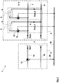
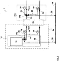
- Figure 1 shows a section of a heating system 1 with a primary circuit 2 and a secondary circuit 3, which are coupled via a transfer point 3.
- a first circulating pump 17 to be controlled conveys a heating medium in the primary circuit 2.
- the secondary circuit 4 there are two speed-controlled second circulating pumps 12, each belonging to a consumer circuit 5 and conveying a heating medium in the respective consumer circuit 5. In terms of flow, these circulating pumps 12 are parallel. Thus the consumer circuits 5 are also parallel.
- Each consumer circuit 5 forms a part of the secondary circuit 4 and comprises a local flow 10 and a local return 9.
- the local flows 10 emanate from a central secondary flow line 7, which is connected to the secondary side of the transfer point 3.
- the local returns 9 open into a central secondary return line 7, which is also connected to the secondary side of the transfer point 3.
- the consumer 6 and the consumer circuit pump 12 are in series, the consumer circuit pump 12 being arranged in the local flow 10.
- the two thick lines next to the second or right consumer circuit 5 indicate that the secondary circuit 4 can also include further consumer circuits 5.
- the secondary circuit 4 can also include only one consumer circuit 5, so that in this case only a single second circulating pump 12 is accordingly present.
- the consumer groups 5 do not have to include just a single consumer 6, as shown in Figure 1 is shown. Rather, any number of consumers 6 can be present in each consumer circuit 5, which consumers can be in series and / or parallel to one another as desired.
- the transfer point 3 can be a heat exchanger 3a (see Figure 9 ), a hydraulic switch 3b (see Figure 10 ) or a low-loss distributor 3c (see Figure 11 ) be.
- the volume flow V ⁇ pri on the primary side 2 can be set largely without affecting the volume flow V ⁇ sec on the secondary side 4 because the circuits 2, 4 are hydraulically decoupled.
- a heat exchanger 3a there is no mass transfer between the primary and the secondary side, so that in Primary circuit 2 and in the secondary circuit 4 different heat transfer media can be used.
- the first circulating pump 17 to be controlled is located in the primary-side central supply line 15, which leads into the primary side of the transfer point 3.
- a central primary return line 16 also leads away from the transfer point 3 on the primary side.
- the primary-side central return line 16 and the primary-side central supply line 15 are connected in such a way that they convey the same volume flow V ⁇ pri .
- the first circulating pump 17 can either be a feeder pump 17c, ie it can be part of a hydraulically closed feeder circuit 30, as shown in FIG Figure 4 is illustrated, or a generator circuit pump 17b, ie part of a generator circuit 14, as it is in the Figures 3 and 4th is shown.
- a volume flow V ⁇ pri flows which corresponds to the flow rate of the first circulating pump 17 to be regulated.
- the secondary volume flow V ⁇ sec downstream of the transfer point 3 in the central flow line 7, the secondary volume flow V ⁇ sec , from which the consumer circuit volume flows V ⁇ sec, i , ie here the two partial flows V ⁇ sec, 1 and V ⁇ sec, 2 depart.
- these consumer circuit volume flows V ⁇ sec, i correspond to the delivery flow of the respective consumer circuit pump 12 in the corresponding consumer circuit 5.
- the volume flow V ⁇ pri of the first circulation pump 17 is now regulated functionally as a function of the volume flow V ⁇ sec of the secondary circuit 4 downstream of the transfer point 3.
- the volume flow V may sec of the secondary circuit 4 behind the transfer point 3 is measured or determined by calculation, and as a target value V pri, should set in the first circulation pump 17 or from the measured or mathematically calculated flow rate V 4 sec of the secondary circuit, a target value V pri is to calculated for the volume flow of the first circulating pump 17 and set in the first circulating pump.
- Equation G2 results in the temperature spreads ⁇ T pri , ⁇ T sec on both Pages of the transfer point 3 are the same, because V ⁇ pri and V ⁇ sec are then shortened out.
- Equation G2 results in two possible measured variables for regulating the speed of the primary-side circulating pump 17 in such a way that the primary volume flow Vstrom pri is approximated to the demand. Either via the temperature spread ⁇ T pri in the primary circuit 2, which is to approximate the temperature spread ⁇ T sec in the secondary circuit 4, or via the primary-side volume flow V ⁇ pri , which is to approximate the secondary-side volume flow V ⁇ sec .
- the first example shown comprises the primary circuit 2 a centrifugal pump 17 to be regulated, the secondary circuit 4 two or more regulated, fluidically parallel conveying consumer circuit pumps 12.
- the primary-side centrifugal pump 17 can be a feeder pump 17c, which is due to the excessive distance between the generator circuit (s) and consumer circuits 5a and the associated hydraulic resistances in the pipeline system convey the heat transfer medium to the transfer point 3 to the consumer circuits 5a.
- the primary-side centrifugal pump 17 can also be a generator pump 17b.
- V ⁇ pri For the volume flow control of the primary centrifugal pump 17, its current delivery flow V ⁇ pri is used as an actual value. This can either be measured directly inside or outside the centrifugal pump 17, for example by means of a volume flow sensor, or it can be calculated or estimated from other physical variables. A calculation can be made, for example, from the differential pressure generated by the pump and the pump speed. An estimate can be made on the basis of model equations for the mechanical-hydraulic pump-motor model, possibly taking into account the electrical-mechanical motor model, as is usually the case with control-technical observers.
- equation G3 is converted to the primary-side volume flow V ⁇ pri .
- V ⁇ sec, 1 , V ⁇ sec, 2 , ..., V ⁇ sec, n can either be measured, calculated or estimated directly inside or outside the consumer circuit pumps 12, as was explained above for the primary centrifugal pump.
- the consumer circuit volume flows V ⁇ sec, 1 , V ⁇ sec, 2 , ..., V ⁇ sec, n can be determined by independent volume flow measuring devices or by volume flow sensors within the consumer circuit pumps 12.
- Independent volume flow measuring devices have the advantage that they can be installed at any point within a consumer circuit 5. This is particularly advantageous if there are recirculations in the consumer circuit 5 and the consumer circuit pumps 12 convey the volume flow through the consumer 6, but not the lower consumer circuit volume flow, which will be illustrated below.
- determining the consumer circuit volume flows by the consumer circuit pumps has the advantage that additional external measurement technology for volume flow measurement in the consumer circuits can be dispensed with. This also eliminates the need to provide additional power supplies for such external measurement technology and additional communication lines for the transmission of the measurement data, whereby the installation, maintenance and cost outlay is minimal.
- Modern electronically controlled circulating pump units usually determine the flow rate Q for their control, for operating point detection and / or for other additional functions such as error analyzes, so that a corresponding measurement technology and / or software-based determination process is already available in the pump electronics. Ideally, such pump units with integrated volume flow determination can be used as consumer circuit pumps 12.
- the centrifugal pump 17 to be controlled the setpoint for your volume flow control in its pump electronics on the basis of the Consumer circuit volume flows V ⁇ sec, 1 determined automatically.
- the determined consumer circuit volume flows V ⁇ sec, 1 are communicated to the centrifugal pump to be controlled.
- an evaluation unit is integrated in the pump electronics of the primary centrifugal pump 17, which calculates the target volume flow V ⁇ pri on the primary side according to equations G5 and G6 from the consumer circuit volume flows V ⁇ sec, 1 , V ⁇ sec, 2 , ..., V ⁇ sec, n calculated with possibly given factor k, provided that there is no media equality.
- the consumer circuit volume flows V ⁇ sec, 1 can advantageously be transmitted from the respective measuring point directly to the primary-side centrifugal pump, ie, for example, from the independent volume flow measuring devices or from the individual consumer circuit pumps 12.
- the setpoint volume flow V ⁇ pri should according to equations G5 and G6 from the consumer circuit volume flows V ⁇ sec, i can also be determined in an external evaluation unit 28, for example in a central communication device 28 which, on the one hand, is in communication with the consumer circuit pumps 12, to receive or request the determined consumer circuit volume flows V ⁇ sec, 1 , on the other hand is in communication with the primary-side pump 17 to be controlled in order to transmit the determined setpoint volume flow V ⁇ pri, should .
- the weighting factor k of the external evaluation unit what has been said above applies analogously.
- the volume flow measuring devices and / or consumer circuit pumps 12 have suitable communication interfaces in order to transmit the consumer circuit volume flow data.
- Modern pump units nowadays already have communication interfaces such as CAN. LON. BACnet, Modbus, LAN etc, so that no additional communication units are required to transmit the volume flow data to the pump to be controlled.
- Radio modules for pump units are also well known.
- the figures illustrate wired communication by means of data lines 20 which are connected to the data network 19 to which the primary-side centrifugal pump 17 is also connected.
- a consumer circuit volume flow V ⁇ sec, 1 is not identical to the consumer volume flow V ⁇ consumer, i of the consumer circuit pump 12 arranged in the corresponding consumer circuit .
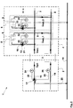
- a forward mixer 11 in the corresponding consumer circuit 5a can be used for this purpose Figure 2 executed in the form of a three-way control valve, which is arranged in the local flow line 10 of the consumer circuit 5a and connected to the local return line 9 via a mixing line 22.
- the flow mixer 11 can be motor-operated, in particular autonomously temperature-controlled, in order to obtain a predetermined flow temperature T VL, sec, i in the corresponding consumer circuit 5a.
- the sum of the volume flows conveyed by the consumer circuit pumps 12 is greater than the volume flow V ⁇ sec provided by the transfer point 3 or flowing back to the transfer point 3 .
- each volume flow V Volumen consumer, i determined by the consumer circuit pumps 12 can be corrected by multiplication by a consumer circuit-specific correction value C i .
- This correction value C i is preferably formed by the ratio of the temperature difference between the local flow 10 downstream of the mixer 11 and the local return 9 of the corresponding consumer circuit 5a to the temperature difference between the central secondary-side flow 7 and the local return 9 of the corresponding consumer circuit 5a.
- the flow temperature on the primary side can be used instead of the central flow temperature on the secondary side. This has the advantage that no additional measurement technology is required to measure the secondary flow temperature. Rather, measurement technology can be used to record the temperatures that is integrated or at least partially integrated into the centrifugal pumps.
- the temperatures in the local flow 10 of the consumer circuit 5a downstream of the mixer 11, in the local return 8 and in the primary flow 15 can suitably be measured and used to calculate the correction value C i for this consumer circuit 5a according to the aforementioned ratio.
- the temperature in the local flow 7 can be determined by means of a first temperature sensor 31, 33 (see FIG Figure 2-4 ), which is arranged outside of the consumer circuit pump 12. Alternatively, it can also be used in this be integrated and measure the temperature of the delivery flow, since the consumer circuit pump 12 is arranged in the feed line 10 anyway, so that the temperature of the pumped medium is the feed temperature.
- the temperature in the local return 9 can be determined by means of a second temperature sensor 32, 34 (see FIG Figure 2-4 ), which is arranged outside of the consumer circuit pump 12.
- the second temperature sensor can be integrated in this pump 12 and detect the temperature of the conveyed medium.
- the temperature in the primary central flow 15 can be determined by means of a third temperature sensor 24 (see FIG Figure 2-4 ) take place outside the pump 17 to be controlled in the central secondary-side flow 7 or outside the pump 17 to be controlled in the primary-side flow 15 (see Figure 2-4 ) or can be arranged within the pump 17 to be regulated in the primary-side flow 15.
- the first and second temperature sensors 31, 32 can be in communication with the consumer circuit pump 12 of the corresponding consumer circuit 5a and transmit the temperature measurement values to the pump electronics of this consumer circuit pump 12. In the case of sensors integrated into the pump as well as sensors external to the pump, this can be done in a wired manner via measuring lines 25 or by radio.
- the consumer circuit pump 12 then transmits the measured temperature values to the primary-side pump 17 to be regulated, in whose pump electronics the correction value is calculated.
- the temperature sensors can also have their own communication interface with a corresponding communication capability and can be connected to the data network 19 by radio or cable. This enables the temperature measurement values to be fed directly to the pump 17 to be regulated, so that there is no need to take a detour via the consumer circuit pumps 12 with regard to data transmission.
- the third temperature sensor 24 is in communication with the primary-side centrifugal pump 17 to be regulated and the temperature measured values are transmitted to them Transfer pump electronics. This can also be done both with the pump-integrated sensor and with the pump-external sensor, wired via a measuring line 25 or by radio.
- the primary-side pump 17 to be controlled thus receives measured values from all three temperature sensors 24, 31, 32 or 24, 33, 34 and can calculate the consumer-specific correction value C i by dividing the difference between the local flow and return temperatures by the difference between the central Flow and local return temperature is divided.
- the primary-side pump 17 to be regulated does not necessarily have to perform the calculation of the correction value C i . Rather, this can also be done in one of the consumer pumps so that they provide the correct consumer circuit volume flow. In this case, the measured temperature values must be transmitted to the corresponding consumer circuit pump 12, ie the central flow temperature to all consumer circuit pumps 12. This can be done via the data network 19 or by radio. Furthermore, it can be carried out by the pump 17 to be regulated or by the third temperature sensor.
- the calculation of the correction value C i can take place in the central evaluation unit which provides the setpoint volume flow for the primary-side pump to be regulated.
- the measured temperature values are then to be transmitted to this central evaluation unit.
- the temperature measurement in the local flow 10, local return 9 of the consumer circuit 5a and the primary flow 15 has the advantage that the measurement technology available in the pumps can be largely used, i.e. additional, independent external temperature measurement technology can be dispensed with in order to obtain the respective correction value To determine C i . Because ideally the respective medium temperature corresponds to the flow temperature, at least if the corresponding pump is in the flow. If the consumer circuit pump 12 is integrated into the local flow 10, it determines the flow temperature accordingly. If it is integrated into the return 9, it measures the accordingly Return temperature. The second temperature sensor 34 connected to the respective consumer circuit pump 12 is then to be integrated in the corresponding other flow path.
- the third temperature sensor is to be arranged in the central secondary-side supply 7.
- the communication technology connection may be difficult because the primary-side pump 17 to be controlled and the consumer circuit pump in the case of heating systems 1 that extend far can be far away from the measuring point in the central secondary flow 7. It is therefore advantageous here to equip the third temperature sensor with its own communication unit and to connect it to the data network 19.
- the calculation of the primary target volume flow is preferably carried out using equations G5 and G11a and b.
- V ⁇ sec V ⁇ consumer , 1 ⁇ C. 1 + V ⁇ consumer , 2 ⁇ C. 2 + V ⁇ sec , 3
- T VL , sec T VL , pri - ⁇ T pri - sec
- the calculation of the consumer group-specific correction value C i in G11b can be replaced by G14:
- C. i T VL . consumer , i - T RL . consumer , i T VL . pri - ⁇ T pri - sec - T RL . consumer , i
- no mixer is installed in at least one heating circuit so that the temperature drop can be measured continuously.
- the temperature drop ⁇ T pri-sec over the transfer point 3 in the flow 15, 10 can be measured at any time.
- the temperature drop ⁇ T pri-sec is calculated and stored at least once. Since this calculation is based on measured values that are already available together at one of the evaluation points, i.e. preferably in the primary centrifugal pump 17 to be controlled, alternatively in the respective consumer circuit pump 12 or in the central evaluation unit, the only information required there is when the mixer is full is open. If this information is available, the temperature drop ⁇ T pri-sec is derived from the difference between the flow temperatures T VL then present . pri and T VL.consumer, i calculated.
- the information can be provided, for example, via a corresponding opening signal from the mixer 11.
- the opening signal can be transmitted via cable or radio to the appropriate evaluation point.
- a corresponding message line can be used between the evaluation point and the mixer 11 exist, or the mixer 11 has a communication unit which enables it to be connected to the data network 19.
- the temperature drop ⁇ T pri-sec is preferably determined repeatedly at time intervals, in particular again and again when a mixer 11 is fully open. This has the advantage that corrections and averaging of the temperature drop ⁇ T pri-sec are possible.
- the primary-side return temperature T RL, pri must also be measured by means of a fourth temperature sensor 26.
- the return temperature T RL.pri is now also measured in the primary circuit 2, so that all the variables in equation G17 are known and this can be used to calculate the temperature drop.
- the media circulating in the primary circuit 2 and the secondary circuit 4 can differ.
- the weighting factor k is not equal to 1 for this media difference. Since the heating / cooling medium or media to be used is / are determined when the heating or cooling system is designed, its density (s) and specific heat capacity (s) are also determined ) known in principle and can be specified for the volume flow control of the primary-side pump 17 as such or in the form of the weighting factor k already calculated according to equation G5.
- the temperature spread ⁇ T pri and the volume flow V ⁇ pri on the primary side 2 of the transfer point 3 are determined, in particular measured, as has already been described in detail above with reference to the various options.
- the primary-side volume flow Vi pri can preferably be determined computationally by a volume flow sensor integrated in the pump 17 to be regulated or from other variables within the pump 17.
- the third 24 and fourth 26 temperature sensors can be used to determine the temperature spreads, the pump electronics of the primary-side pump 17 to be regulated preferably determining the difference from these sensor values.
- the volume flow V ⁇ sec on the secondary side 4 can be calculated according to the invention according to one of the previously described equations G6, G7 or G11a.
- the secondary-side return temperature T RL, sec is preferably determined from the mixing rule according to equation G18.
- the temperature drop ⁇ T pri-sec can be determined in one of the ways described above using one of equations 15 or 16 or 17 and 18.
- calculation rule for the weighting factor k is dispensed with at this point for reasons of clarity and legibility. Nevertheless, the calculation rule can be represented and calculated as a mathematically self-contained expression.
- the set volume flow V ⁇ pri to be regulated in the primary-side centrifugal pump 17 can then be calculated according to equation 5 and set accordingly in the pump control.
- the centrifugal pump 17 to be controlled shown in the primary circuit 2 can be a generator pump 17b, as shown in FIG Figure 3 , 4th or 5 is shown in the flow 15 of a generator 18, or a feeder pump 17c, as shown in FIG Figure 4 is arranged in the flow 35 of a feeder circuit 30.
- the generator pump 17b and the feed pump 17c can also be arranged in the corresponding return.
- the primary circuit 2 can include more than one generator circuit 14.
- the primary circuit 2 can include more than one generator circuit 14.
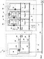
- three such producer groups 14a, 14b are shown.
- Each producer group may include one or more producers 18, albeit in Figure 5 only one producer 18 per producer group 14a, 14b is shown.
- the producers provide the heating or cooling capacity in the case of a cooling system.
- a generator pump 17a, 17b is assigned to each generator circuit 14a, 14b and drives the heating medium in the respective local feed line 20 and in the central feed line 15 promotes.
- heating system 1 of this type it is not necessary to regulate all generator pumps 17a, 17b, or to regulate them identically. Rather, the varying peak load that occurs as required can be covered with a single one of the generating groups 14b and the base load can be provided with the remaining generating groups 14a.
- the producers 18 in these circles 14a run at maximum thermal power.
- the generator 18 in the peak load generator circuit 14b modulates its thermal output according to the desired central primary-side flow temperature T VL, pri or the central secondary-side flow temperature T VL, sec , with the peak load pump 17b adapting. If the thermal output reaches a control limit without the desired flow temperature T VL, pri or T VL, sec being reached, a base load generator circuit 14a including the associated generator (s) and the associated base load pump 17a must be switched off or on.
- that generator pump 17b that is assigned to the generator circuit 14b serving a peak load is regulated in such a way that the total volume flow V ⁇ pri on the primary side 2 corresponds to the volume flow V ⁇ sec on the secondary side 4.
- the pump assigned to the generator circuit 14b serving the peak load is therefore also called the peak load pump 17b within the meaning of the invention, and the pump or pumps 17a assigned to the generator circuit (s) 14a serving the base load are called the base load pumps.
- V ⁇ pri, p of the pump 17b to be regulated is suitably the setpoint value of the control.
- k ⁇ sec ⁇ c sec ⁇ pri ⁇ c p , pri
- the calculation rule for the setpoint V ⁇ pri, k soll differs in the variant with more than one generator circuit 14 from that according to equation G5 only in that the volume flows of the other generator circuit (s) 14, i.e. the base load pumps, are also determined and be subtracted from the determined, optionally weighted volume flow V ⁇ sec of the secondary side 4.
- the volume flows of the generator pumps 14a, 14b can be determined by measurement or computation analogous to the previous descriptions, either within the corresponding pump or outside the same, either by means of the pump itself or by means of a volume flow measuring device.
- the determined volume flows of the base load generator circuits 14a are then transmitted to the peak load pump 17b or to another evaluation unit in order to measure the Setpoint volume flow V ⁇ pri, k on the primary side should be determined for the peak load pump 17b to be regulated.
- the transmission can be done by radio or as in Figure 5 shown, via the data lines 20 and the data network 19.
- the calculation of the secondary volume flow V ⁇ sec in equation G23 can, as before with the other design variants, in particular take place according to one of the equations G6, G7 or G11a, in particular also for media-different circuits on the primary 2 and secondary side 4 according to equation G19.
- the varying, if necessary, peak load can be covered with two generator circuits 14b, whereas the base load is provided with the remaining generator circuit (s) 14a.
- the base load generator 18 in this circuit 14a run with maximum thermal power.
- Only the pumps 17b of the peak load generator circuits 14b adapt to the fluctuations in the consumer-side volume flow in order to achieve energy-efficient heating pump control.
- the method according to the invention is therefore (only) applied to these peak load pumps 17b, while the base load pump 17a is not regulated or is regulated differently. There are then two first primary-side circulation pumps that are regulated according to the invention.
- the volume flow which is formed by the sum of the generator circuits 14b serving a peak load, is determined analogously to equation G23 and this volume flow is distributed uniformly or in a predetermined ratio to the peak load pumps 17b.
- the volume flow ratio corresponds to that Ratio of the thermal outputs of the generating groups serving a peak load.
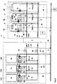
- a mixer 21 can be arranged in the primary return line 16 or primary local return line 19 in the generator circuit 14 or in one, several or all of the generator circuits 14a, 14b.
- Such mixer-affected producer groups 14a ', 14b' are in Figure 6 shown, with both the base load generator circuits and the peak load generator circuit having such a mixer 21 here.
- the respective temperatures T VL, producer, i and T RL, producer, i of the local secondary flow line 20 and the local secondary return line 19 are required. According to the invention, these are determined accordingly and transmitted to the evaluation point for calculating the setpoint volume flow, ie for example to the primary centrifugal pump 17 or peak load pump 17b to be regulated or an external evaluation unit.
- the determination can be made by measuring, calculating from other measured variables or estimating from model variables.
- the transmission can take place by radio or wired, in particular via measuring lines 25 and the data network 19, which connects the location of the determination with the evaluation point in terms of communication.
- the temperature T VL, producer, i in the primary local flow 20 of a generator circuit 14a ', 14b' before the branch to the return mixer 21 can be measured by means of temperature sensor 37 and transmitted to the pump electronics of the generator pump 17a, 17b of this generator circuit become.
- the temperature T RL, producer, i in the primary local return 20 of a generator circuit 14a ', 14b' downstream of the return mixer 21 can be measured by means of a temperature sensor 38 and transmitted to the pump electronics of the generator pump 17a, 17b of this generator circuit 14a ', 14b'.
- the temperature sensor 37 arranged in the local flow 20 can be integrated into the corresponding generator pump 17a, 17b and thus transmit its measurement signal directly to its pump electronics.
- the temperature sensor 38 arranged in the local return 19 it can be connected to the pump electronics of the said pump 17a, 17b via a measuring line 25.
- a feeder circuit 30 can be connected upstream of the transfer point 3 to the consumer circuits 4 in order to overcome long distances and associated pressure losses.
- This feeder circuit 30 connects directly to the primary side of the transfer point 3 and is connected to the secondary side of a second transfer point 29, which in turn connects to the generator circuit 14 on its primary side.
- a single generator circuit 14 is present on the generator side.
- the feed pump 17c arranged in the feeder circuit 30 is regulated according to the method according to the invention, ie its volume flow is regulated as a function of the sum of the consumer-specific volume flows.
- This volume flow control can also be used for the generator pump 17b arranged in the generator circuit 14.
- the volume flow of this generator pump can also be regulated depending on the sum of the consumer-specific volume flows. This can be done in two ways, directly or indirectly.
- the generator pump 17b can receive the required volume flow setpoint, for example either from the feeder pump 17c, which calculates this value, or from the central evaluation unit.
- the generator pump 17b can, however, also calculate the volume flow setpoint itself.
- the volume flow and temperature values required for this are then obtained from the consumer circuits 5a, 5b and the feeder circuit 30 transmitted accordingly to the generator pump 17b. In both cases, no temperatures need to be determined in the generating circuit 14.
- the generator pump can be regulated in such a way that its volume flow is regulated to the actual volume flow of the feeder pump 17c. This case is ultimately to be treated as if the feeder circuit 30 were a single or the only consumer circuit.
- the second transfer point 29 then takes the place of the first transfer point 3 from a control point of view.
- the generator pump 17b does not have to be regulated to a total volume flow, but only to the one volume flow in the feeder circuit, which may be increased by the weighting factor k in the event of media differences multiply is. Otherwise, this case should be treated analogously to the above explanations and equations.
Landscapes
- Engineering & Computer Science (AREA)
- Physics & Mathematics (AREA)
- Mechanical Engineering (AREA)
- General Engineering & Computer Science (AREA)
- General Physics & Mathematics (AREA)
- Automation & Control Theory (AREA)
- Thermal Sciences (AREA)
- Chemical & Material Sciences (AREA)
- Combustion & Propulsion (AREA)
- Artificial Intelligence (AREA)
- Computer Vision & Pattern Recognition (AREA)
- Evolutionary Computation (AREA)
- Medical Informatics (AREA)
- Software Systems (AREA)
- Health & Medical Sciences (AREA)
- Air Conditioning Control Device (AREA)
- Cooling Or The Like Of Electrical Apparatus (AREA)
- Control Of Positive-Displacement Pumps (AREA)
Description
Die Erfindung betrifft ein Verfahren zur Regelung wenigstens einer ersten Umwälzpumpe einer Heizungs- oder Kühlungsanlage, die einen Primärkreis und einen mit diesem an einer Übergabestelle gekoppelten Sekundärkreis aufweist, wobei die erste Umwälzpumpe ein Heiz- oder Kühlmedium im Primärkreis fördert und im Sekundärkreis zumindest eine drehzahlgeregelte, zweite Umwälzpumpe liegt, die ein Heiz- oder Kühlmedium in zumindest einem Teilbereich des Sekundärkreises fördert.The invention relates to a method for regulating at least one first circulation pump of a heating or cooling system, which has a primary circuit and a secondary circuit coupled to it at a transfer point, the first circulation pump conveying a heating or cooling medium in the primary circuit and at least one speed-controlled, second circulation pump is located, which promotes a heating or cooling medium in at least a portion of the secondary circuit.
Ein Verfahren gemäß dem Oberbegriff des Anspruchs 1 ist aus der Patentschrift
In Anlagen zur Beheizung und/oder Kühlung von Gebäuden mit flüssigen Wärmeträgern ist es üblich, die Verbraucher auf mehrere Verbraucherkreise aufzuteilen. Diese Aufteilung kann z.B. getrennt nach Gebäudeteilen oder getrennt nach unterschiedlichen Verbraucherarten erfolgen. Verbraucherarten sind beispielsweise Heizkörper oder Heiz- bzw. Kühlflächen bei Fussbodenheizungen oder Deckenheizungen bzw. Kühldecken. Hinsichtlich der Gebäudeteile kann eine Aufteilung beispielsweise nach Wohnungen oder Etagen erfolgen. Jeder Verbraucherkreis umfasst dann einen oder mehr Verbraucher sowie eine diesen oder diese versorgende Verbraucherkreispumpe. Zudem ist meist in jedem Verbraucherkreis zumindest einem Verbraucher ein regelndes Stellglied angeordnet, das den Volumenstrom durch den oder die entsprechenden Verbraucher einstellt. Alternativ kann die Regelung des Volumenstroms durch die Verbraucher direkt durch Drehzahlregelung der Pumpe im Verbraucherkreis erfolgen.In systems for heating and / or cooling buildings with liquid heat transfer media, it is common to divide the consumers into several consumer groups. This division can e.g. be carried out separately according to building parts or separately according to different types of consumers. Types of consumers are, for example, radiators or heating or cooling surfaces in underfloor heating or ceiling heating or cooling ceilings. With regard to the building parts, a division can be made, for example, according to apartments or floors. Each consumer circuit then includes one or more consumers and a consumer circuit pump that supplies them. In addition, a regulating actuator, which adjusts the volume flow through the corresponding consumer or consumers, is usually arranged in at least one consumer in each consumer circuit. Alternatively, the volume flow can be regulated by the consumers directly by regulating the speed of the pump in the consumer circuit.
Die Verbraucherkreise werden in der Regel über gemeinsame Versorgungsleitungen, d.h. eine gemeinsame Vorlaufleitung und Rücklaufsammelleitung mit wenigstens einem Wärme- oder Kälteerzeuger eines oder mehrerer Erzeugerkreise verbunden. Bei kombinierten Anlagen, die sowohl Heizen als auch Kühlen können, sind die Verbraucher entsprechend mit zumindest einem Wärmeerzeuger und zumindest einem Kälteerzeuger jeweils eines eigenen Erzeugerkreises verbunden, wobei wahlweise der Erzeugerkreis mit dem einen oder anderen Erzeugertyp in Betrieb ist.The consumer circuits are usually via common supply lines, ie a common flow line and return collecting line with at least connected to a heat or cold generator of one or more generator circuits. In the case of combined systems that can heat as well as cool, the consumers are connected to at least one heat generator and at least one cold generator each with their own generator circuit, with the generator circuit optionally operating with one or the other generator type.
Der Erzeugerkreis oder die Erzeugerkreise sind häufig mittels einer Übergabestelle an die Verbraucherkreise gekoppelt. Eine solche Übergabestelle kann beispielsweise eine hydraulische Weiche, ein Wärmetauscher oder eine Überströmleitung sein, wobei die verschiedenen Übergabestellen unterschiedliche Eigenschaften haben und verschiedene Anforderungen erfüllen. Das Ankoppeln kann direkt erfolgen oder alternativ über einen Zubringerkreis, wenn beispielsweise aufgrund der Entfernung zwischen Erzeugerkreis und Verbraucherkreis große Druckverluste überwunden werden müssen. Dadurch ergeben sich dann zwei Übergabestellen, eine erste Übergabestelle zwischen Erzeugerkreis(en) und Zubringerkreis und eine zweite Übergabestelle zwischen Zubringerkreis und Verbraucherkreisen. Aus Sicht der Übergabestelle zu den Verbraucherkreisen sind der oder die Erzeugerkreis(e) bzw. der Zubringerkreis auf der Primärseite, wohingegen die Verbraucherkreise auf der Sekundärseite der Übergabestelle liegen.The producer group or groups are often linked to the consumer groups by means of a transfer point. Such a transfer point can be, for example, a hydraulic switch, a heat exchanger or an overflow line, the different transfer points having different properties and meeting different requirements. The coupling can take place directly or alternatively via a feeder circuit if, for example, due to the distance between the generator circuit and the consumer circuit, large pressure losses have to be overcome. This then results in two transfer points, a first transfer point between the producer group (s) and the feeder circuit and a second transfer point between the feeder circuit and consumer groups. From the point of view of the transfer point to the consumer circuits, the producer group (s) or the feeder circuit are on the primary side, whereas the consumer circuits are on the secondary side of the transfer point.
Im Allgemeinen gilt, dass die benötigten Volumenströme in der Anlage durch die Verbraucher definiert werden. Denn in der Regel wird der Volumenstrom in einem Verbraucherkreis über die den einzelnen Verbrauchern zugeordneten Stellglieder eingeregelt. Um den Betrieb der Verbraucherkreispumpen daran sinnvoll anzupassen, werden drehzahlregelbare Kreiselpumpe mit einer Pumpenelektronik eingesetzt, bei denen als bewährte Regelungsarten eine sogenannte Konstantdruckregelung, auch Δp-c Regelung genannt, und eine Variabeldruckregelung, sogenannte Δp-v Regelung zur Verfügung stehen, welche in der Pumpenelektronik der Verbraucherkreispumpen ausgewählt werden können. Alternativ zur indirekten Beeinflussung der Pumpendrehzahl über Stellglieder, kann die Drehzahl der Kreiselpumpe direkt, z.B. durch eine Temperaturregelung, Feuchteregelung oder Volumenstromregelung beeinflusst werden. Dagegen ist eine bedarfsabhängige Regelung der primärseitig der Übergabestelle zum Verbraucherkreis angeordneten Pumpen nicht etabliert. Bekannt sind verschiedene Verfahren, die primärseitige Pumpe entsprechend einer oder mehrerer Temperaturdifferenzen an der hydraulischen Weiche bzw. am Wärmeübertrager zu regeln. Diese Verfahren sind mess- und regelungstechnisch aufwendig und/oder ermöglichen lediglich eine unvollständige Anpassung an den Bedarf.In general, the required volume flows in the system are defined by the consumers. As a rule, the volume flow in a consumer circuit is regulated via the actuators assigned to the individual consumers. In order to adapt the operation of the consumer circuit pumps in a meaningful way, speed-controllable centrifugal pumps with pump electronics are used, in which a so-called constant pressure control, also called Δp-c control, and a variable pressure control, so-called Δp-v control, are available as proven control types, which are available in the pump electronics the consumer circuit pumps can be selected. As an alternative to indirectly influencing the pump speed via actuators, the speed of the centrifugal pump can be influenced directly, for example by temperature control, humidity control or volume flow control. In contrast, a demand-dependent regulation of the pumps arranged on the primary side of the transfer point to the consumer circuit is not established. Various are known Method of regulating the primary-side pump according to one or more temperature differences at the hydraulic separator or at the heat exchanger. These methods are complex in terms of measurement and control technology and / or only allow incomplete adaptation to requirements.
Es ist daher Aufgabe der vorliegenden Erfindung, eine bedarfsabhängige Regelung für eine drehzahlregelbare Kreiselpumpe bereitzustellen, die primärseitig einer Übergabestelle zu Verbraucherkreisen in einer Heizungs- oder Kühlanlage angeordnet ist.It is therefore the object of the present invention to provide a demand-dependent control for a speed-controllable centrifugal pump which is arranged on the primary side of a transfer point to consumer circuits in a heating or cooling system.
Diese Aufgabe wird durch das Verfahren mit den Merkmalen des Anspruch 1 gelöst. Vorteilhafte Weiterbildungen sind in den Unteransprüchen angegeben und werden nachfolgend beschrieben.This object is achieved by the method having the features of
Erfindungsgemäß wird ein Verfahren zur Regelung wenigstens einer ersten Umwälzpumpe einer Heizungs- oder Kühlungsanlage vorgeschlagen, die einen Primärkreis und einen mit diesem an einer Übergabestelle gekoppelten Sekundärkreis aufweist, wobei die erste Umwälzpumpe ein Heiz- oder Kühlmedium im Primärkreis fördert und im Sekundärkreis zumindest eine drehzahlgeregelte, zweite Umwälzpumpe liegt, die ein Heiz- oder Kühlmedium in zumindest einem Teilbereich des Sekundärkreises fördert, wobei der Volumenstrom der ersten Umwälzpumpe in funktionaler Abhängigkeit von dem Volumenstrom des Sekundärkreises hinter der Übergabestelle geregelt wird.According to the invention, a method for regulating at least one first circulating pump of a heating or cooling system is proposed which has a primary circuit and a secondary circuit coupled to this at a transfer point, the first circulating pump conveying a heating or cooling medium in the primary circuit and at least one speed-controlled, second circulating pump is located, which promotes a heating or cooling medium in at least a portion of the secondary circuit, the volume flow of the first circulating pump is controlled functionally dependent on the volume flow of the secondary circuit behind the transfer point.
Durch eine derartige Volumenstromregelung in Abhängigkeit des Volumenstroms der Sekundärseite lässt sich eine verbrauchsabhängige und damit energieeffiziente Regelung der auf der Primärseite liegenden Pumpe realisieren. Der Primärvolumenstrom wird dadurch einerseits ausreichend hoch eingestellt, um den Verbrauchern die gewünschte Wärmeleistung bereitzustellen, und andererseits nicht unnötig hoch sein, um Energie zu sparen.With such a volume flow control as a function of the volume flow on the secondary side, a consumption-dependent and thus energy-efficient control of the pump on the primary side can be implemented. The primary volume flow is set sufficiently high on the one hand to provide the consumers with the desired heat output, and on the other hand not unnecessarily high in order to save energy.
Die erfindungsgemäße Regelung lässt sich auf sämtliche Heizungs- oder Kühlanlagen anwenden, die einen durch zumindest eine Übergabestelle gekoppelten Primär- und Sekundärkreis haben. Dabei entspricht der Primärkreis allgemein der Erzeugerseite, der Sekundärkreis allgemein der Verbraucherseite. Unabhängig voneinander kann der Primärkreis einen oder mehrere Erzeugerkreise und der Sekundärkreis einen oder mehrere Verbraucherkreise umfassen. Primär- und Sekundärkreis können über die Übergabestelle direkt miteinander gekoppelt sein. Alternativ kann jedoch auch ein Zubringerkreis zwischen Primär- und Sekundärkreis liegen, der mit jeweils einer Übergabestelle an den Primärkreis und den Sekundärkreis gekoppelt ist.The regulation according to the invention can be applied to all heating or cooling systems that have a primary and secondary circuit coupled by at least one transfer point. The primary circuit generally corresponds to the Producer side, the secondary circuit generally on the consumer side. Independently of one another, the primary circuit can include one or more generator circuits and the secondary circuit one or more consumer circuits. The primary and secondary circuits can be linked directly to one another via the transfer point. Alternatively, however, there can also be a feeder circuit between the primary and secondary circuits, which is coupled to the primary circuit and the secondary circuit with one transfer point in each case.
Entsprechend dieser Vielzahl von Anlagentopologien kann das erfindungsgemäße Verfahren auf verschiedene Weise Anwendung finden. So kann allein im Hinblick auf die Anlagentopologie
- in einer ersten Ausführungsvariante eine Erzeugerpumpe mit einer Verbraucherpumpe gekoppelt sein,
- in einer zweiten Ausführungsvariante eine Erzeugerpumpe mit zwei oder mehr parallelen Verbraucherpumpen gekoppelt sein (siehe
Figur 3 ), - in einer drittenAusführungsvariante zwei oder mehr parallele Erzeugerpumpe mit zwei oder mehr parallelen Verbraucherpumpen gekoppelt sein (siehe
Figur 5, 6 - in einer vierten Ausführungsvariante eine Zubringerpumpe mit einer Verbraucherpumpe gekoppelt sein,
- in einer fünften Ausführungsvariante eine Zubringerpumpe mit zwei oder mehr parallelen Verbraucherpumpen gekoppelt sein (siehe
Figur 1, 2 - in einer sechsten Ausführungsvariante eine Erzeugerpumpe mit einer Zubringerpumpe gekoppelt sein (siehe
Figur 7 ), - in einer siebten Ausführungsvariante zwei oder mehr parallele Erzeugerpumpen mit einer Zubringerpumpen gekoppelt sein (siehe
Figur 8 ).
- in a first variant, a generator pump can be coupled to a consumer pump,
- In a second variant, a generator pump can be coupled with two or more parallel consumer pumps (see
Figure 3 ), - In a third variant, two or more parallel generator pumps can be coupled with two or more parallel consumer pumps (see
Figure 5, 6 ), - in a fourth variant, a feeder pump can be coupled to a consumer pump,
- In a fifth variant, a feeder pump can be coupled with two or more parallel consumer pumps (see
Figure 1, 2 ), - In a sixth variant, a generator pump can be coupled with a feeder pump (see
Figure 7 ), - In a seventh variant, two or more parallel generator pumps can be coupled with one feed pump (see
Figure 8 ).
Da bei den Ausführungsvarianten vier bis sieben immer nur eine Hälfte der Anlage betrachtet wird, sind entsprechend weitere Ausführungsvarianten durch eine Kombination der Varianten vier und sechs, vier und sieben, fünf und sechs (siehe
Erfindungsgemäß wird der Volumenstrom der ersten Umwälzpumpe in funktionaler Abhängigkeit von dem Volumenstrom des Sekundärkreises hinter der Übergabestelle geregelt. Dies lässt sich mathematisch durch V̇soll = f(V̇sec ) beschreiben, wobei V̇soll der einzuregelnde Volumenstrom der ersten Umwälzpumpe, V̇sec der Volumenstrom des Sekundärkreises hinter der Übergabestelle und f eine mathematische Funktion ist, die einem sekundärseitigen Volumenstrom V̇sec einen entsprechenden Sollvolumenstrom V̇soll für die Umwälzpumpe zuordnet. Ist primärseitig nur eine erste Umwälzpumpe vorhanden (erste, zweite, vierte, fünfte, sechste Ausführungsvariante), entspricht der Sollvolumenstrom dem primärseitigen Volumenstrom V̇pri, so dass dann V̇pri = f(V̇sec ) ist. Sind primärseitig zwei oder mehr erste Umwälzpumpen vorhanden (Ausführungsvarianten drei und sieben), entspricht der Sollvolumenstrom einem erzeugerspezifischen Volumenstrom V̇pri,i, d.h. dem Volumenstrom eines Erzeugerkreises, so dass dann V̇pri,i = f(V̇ec ) ist.According to the invention, the volume flow of the first circulation pump is functionally dependent on the volume flow of the secondary circuit behind the transfer point regulated. This can be described mathematically by V̇ soll = f ( V̇ sec ), where V̇ soll is the volume flow to be regulated by the first circulating pump, V̇ sec the volume flow of the secondary circuit behind the transfer point and f is a mathematical function that gives a secondary volume flow V̇ sec a corresponding set volume flow V̇ should be allocated for the circulation pump. If there is only a first circulation pump on the primary side (first, second, fourth, fifth, sixth variant), the target volume flow corresponds to the primary-side volume flow V pri , so that V̇ pri = f ( V̇ sec ). If there are two or more first circulation pumps on the primary side (design variants three and seven), the target volume flow corresponds to a generator-specific volume flow V̇ pri, i, i.e. the volume flow of a generator circuit , so that V̇ pri, i = f ( V̇ ec ).
Gemäß einer Ausführungsvariante kann die erste Umwälzpumpe so geregelt werden, dass der Volumenstrom V̇pri des Primärkreises vor der Übergabestelle in einem vorgegebenen Verhältnis zu dem Volumenstrom V̇ sec des Sekundärkreises hinter der Übergabestelle steht. Damit lässt sich die funktionale Abhängigkeit mathematisch durch V̇pri = a · V̇sec beschreiben, wobei a das Verhältnis zwischen dem Volumenstrom V̇pri des Primärkreises vor der Übergabestelle und dem Volumenstrom V̇ sec des Sekundärkreises hinter der Übergabestelle darstellt. Die funktionale Abhängigkeit ist somit durch eine lineare Abhängigkeit beschrieben. Im einfachsten Fall kann a = 1 sein. Dies bedeutet, dass die erste Umwälzpumpe so geregelt wird, dass der Volumenstrom V̇pri des Primärkreises vor der Übergabestelle dem Volumenstrom V̇sec des Sekundärkreises hinter der Übergabestelle entspricht. Um ausreichend Regelungsreserve im Sekundärkreis zu haben sollte jedoch ein Verhältnis zwischen 1,0 und 1,3 gewählt werden.According to one embodiment, the first circulating pump can be controlled so that the volume flow V̇ pri of the primary circuit in front of the transfer point is in a predetermined ratio to the volume flow V̇ sec of the secondary circuit behind the transfer point. The functional dependency can thus be described mathematically by V̇ pri = a · V̇ sec , where a represents the ratio between the volume flow V̇ pri of the primary circuit in front of the transfer point and the volume flow V̇ sec of the secondary circuit behind the transfer point. The functional dependency is thus described by a linear dependency. In the simplest case a = 1 can be. This means that the first circulation pump is regulated in such a way that the volume flow V̇ pri of the primary circuit in front of the transfer point corresponds to the volume flow V̇ sec of the secondary circuit behind the transfer point. In order to have sufficient control reserve in the secondary circuit, however, a ratio between 1.0 and 1.3 should be selected.
Alternativ kann die erste Umwälzpumpe so geregelt werden, dass der Volumenstrom V̇pri des Primärkreises vor der Übergabestelle in einem vorgegebenen Abstand zu dem Volumenstrom V̇sec des Sekundärkreises hinter der Übergabestelle einhält. Damit lässt sich die funktionale Abhängigkeit mathematisch durch V̇pri = V̇sec + b beschreiben, wobei b der Abstand zwischen dem Volumenstrom V̇pri des Primärkreises vor der Übergabestelle und dem Volumenstrom V̇ sec des Sekundärkreises hinter der Übergabestelle darstellt, quasi einen Offset bildet, der größer als null ist.Alternatively, the first circulation pump can be regulated so that the volume flow V̇ pri of the primary circuit in front of the transfer point is at a predetermined distance from the volume flow V̇ sec of the secondary circuit behind the transfer point. The functional dependency can thus be mathematically expressed as V̇ pri = V̇ sec + b describe, where b represents the distance between the volume flow V̇ pri of the primary circuit in front of the transfer point and the volume flow V̇ sec of the secondary circuit behind the transfer point, effectively forming an offset that is greater than zero.
Weiterhin kann eine Kombination der beiden letztgenannten Varianten erfolgen, wobei dann die erste Umwälzpumpe so geregelt wird, dass die funktionale Abhängigkeit des Volumenstrom V̇pri des Primärkreises vor der Übergabestelle von dem Volumenstrom V̇sec des Sekundärkreises hinter der Übergabestelle der Funktion V̇pri = a · V̇sec + b entspricht, wobei der Koeffizient a eine lineare Abhängigkeit der beiden Volumenströme und der Koeffizient b einen Offset beschreibt.Furthermore, a combination of the two last-mentioned variants can take place, in which case the first circulation pump is controlled in such a way that the functional dependence of the volume flow V̇ pri of the primary circuit before the transfer point on the volume flow V̇ sec of the secondary circuit behind the transfer point of the function V̇ pri = a V · sec + b , where the coefficient a describes a linear dependence of the two volume flows and the coefficient b describes an offset.
Der Primärkreis kann zumindest einen Erzeugerkreis aufweisen, in dem wenigstens ein Wärme- oder Kälteerzeuger das Heiz- oder Kühlmedium aufheizt oder kühlt und eine mit dem Wärme- oder Kälteerzeuger in Reihe liegende Erzeugerpumpe das Heiz- oder Kühlmedium des Erzeugerkreises fördert, wobei die zu regelnde, erste Umwälzpumpe diese Erzeugerpumpe ist.The primary circuit can have at least one generator circuit in which at least one heat or cold generator heats or cools the heating or cooling medium and a generator pump in series with the heat or cold generator conveys the heating or cooling medium of the generator circuit, the first circulation pump is this generator pump.
Alternativ hierzu bzw. in Weiterbildung dieser Variante kann der Primärkreis eine Anzahl (m) parallel geschalteter Erzeugerkreise aufweisen, in denen jeweils wenigstens ein Wärme- oder Kälteerzeuger das Heiz- oder Kühlmedium aufheizt oder kühlt und jeweils eine mit dem entsprechenden Wärme- oder Kälteerzeuger in Reihe liegende Erzeugerpumpe einen erzeugerspezifischen Volumenstroms V̇pri,i fördert, wobei die zu regelnde erste Umwälzpumpe dann entsprechend eine dieser parallelen Erzeugerpumpen ist.As an alternative to this or in a further development of this variant, the primary circuit can have a number (m) of generator circuits connected in parallel, in each of which at least one heat or cold generator heats or cools the heating or cooling medium and one in series with the corresponding heat or cold generator Lying generator pump promotes a generator-specific volume flow V̇ pri, i , the first circulating pump to be regulated then correspondingly being one of these parallel generator pumps.
Vorzugsweise ist die zu regelnde, erste Umwälzpumpe in diesem Fall diejenige Erzeugerpumpe ist, die in einem eine Spitzenlast bedienenden Erzeugerkreis liegt. Das bedeutet, dass die erfindungsgemäße Volumenstromregelung nur auf diese Spitzenlastpumpe angewendet wird. Die Erzeugerpumpen der anderen, eine Grundlast bereitstellenden Erzeugerkreise sind dagegen nicht oder anders geregelt.In this case, the first circulating pump to be regulated is preferably that generator pump that is located in a generator circuit serving a peak load. This means that the volume flow control according to the invention is only applied to this peak load pump. The generator pumps of the other generator groups providing a base load, however, are not regulated or regulated differently.
Wie bereits zuvor angesprochen, kann der Erzeugerkreis oder können die Erzeugerkreise mittels der Übergabestelle direkt mit dem Sekundärkreis verbunden sein, d.h. ohne Zwischenschaltung eines Zubringerkreises.As already mentioned above, the producer group or the producer groups can be connected directly to the secondary circuit by means of the transfer point, i.e. without the interposition of a feeder circuit.
Gemäß einer alternativen Variante kann ein solcher Zubringerkreis jedoch vorhanden sein, um Druckverluste bei langen Förderdistanzen zu kompensieren. Ein solcher Zubringerkreis kann aus Sicht der Übergabestelle zum Sekundärkreis/ Verbraucherseite als Teil des Primärkreises, d.h. als Teil der Erzeugerseite verstanden werden. Der Erzeugerkreis oder die Erzeugerkreise sind dann mittels der Übergabestelle indirekt mit dem Sekundärkreis verbunden. So kann der Primärkreis einen Zubringerkreis aufweisen, der an der Übergabestelle mit dem Sekundärkreis gekoppelt ist, wobei in dem Zubringerkreis eine Zubringerpumpe liegt, die ein Heiz-oder Kühlmedium im Zubringerkreis fördert, und wobei die zu regelnde, erste Umwälzpumpe diese Zubringerpumpe ist.According to an alternative variant, however, such a feeder circuit can be provided in order to compensate for pressure losses over long conveying distances. From the point of view of the transfer point to the secondary circuit / consumer side, such a feeder circuit can be part of the primary circuit, i.e. be understood as part of the producer side. The producer group or groups are then indirectly connected to the secondary circuit by means of the transfer point. For example, the primary circuit can have a feeder circuit that is coupled to the secondary circuit at the transfer point, with a feeder pump located in the feeder circuit, which conveys a heating or cooling medium in the feeder circuit, and the first circulating pump to be controlled is this feeder pump.
Es ist aber auch möglich, dass der Zubringerkreis Teil des Sekundärkreises ist oder diesen gar bildet. In diesem Fall koppelt die Übergabestelle den Primärkreis mit dem oder den Erzeuger(n) mit diesem Zubringerkreis. Es liegt dann auch hier in dem Zubringerkreis eine Zubringerpumpe, die ein Heiz- oder Kühlmedium im Zubringerkreis fördert. Da diese Zubringerpumpe Teil des Sekundärkreises ist, entspricht die zweite Umwälzpumpe dann dieser Zubringerpumpe. Diese Variante ist insbesondere in Kombination mit einer Erzeugerpumpe zu verstehen, die der ersten, zu regelnden Umwälzpumpe entspricht. Die Zubringerpumpe als besagte zweite Pumpe kann ungeregelt oder autonom geregelt sein, z.B. entsprechend eines Differenzdrucks, einer Temperatur oder eines Volumenstroms.But it is also possible that the feeder circuit is part of the secondary circuit or even forms it. In this case, the transfer point couples the primary circuit with the producer (s) with this feeder circuit. Here, too, there is a feeder pump in the feeder circuit, which pumps a heating or cooling medium in the feeder circuit. Since this feeder pump is part of the secondary circuit, the second circulation pump then corresponds to this feeder pump. This variant is to be understood in particular in combination with a generator pump that corresponds to the first circulating pump to be regulated. The feed pump as said second pump can be unregulated or autonomously regulated, e.g. according to a differential pressure, a temperature or a volume flow.
Gemäß einer anderen Ausführungsvariante kann diese Zubringerpumpe aber ebenso wie die Erzeugerpumpe nach dem erfindungsgemäßen Verfahren volumenstromgeregelt sein. Es gibt dann zwei zu regelnde erste Umwälzpumpen im Primärkreis respektive auf der Erzeugerseite. In dieser Variante weist der Primärkreis einen Zubringerkreis auf, der an der Übergabestelle mit dem Sekundärkreis gekoppelt ist und mittels einer zweiten Übergabestelle mit dem oder den Erzeugerkreis(en) gekoppelt ist, wobei in dem Zubringerkreis eine Zubringerpumpe liegt, die ein Heiz- oder Kühlmedium im Zubringerkreis fördert und eine weitere erste Umwälzpumpe bildet, welche wie die eine erste Umwälzpumpe geregelt wird.According to another embodiment variant, this feed pump, like the generator pump, can, however, be volume flow-regulated according to the method according to the invention. There are then two first circulation pumps to be controlled in the primary circuit or on the generator side. In this variant, the primary circuit has a feeder circuit which is coupled to the secondary circuit at the transfer point and is coupled to the generator circuit (s) by means of a second transfer point, with a feeder pump in the feeder circuit is located, which promotes a heating or cooling medium in the feeder circuit and forms a further first circulation pump, which is regulated like a first circulation pump.
Analog zur Erzeugerseite kann auch der Sekundärkreis einen Verbraucherkreis oder eine Anzahl (n) parallel geschalteter Verbraucherkreise aufweisen, in dem/denen jeweils wenigstens ein Verbraucher die Wärme oder Kälte des Heiz- oder Kühlmediums verbrauch, und in dem oder denen jeweils eine mit dem entsprechenden Verbraucher in Reihe liegende, autonom geregelte Verbraucherpumpe das Heiz- oder Kühlmedium in dem entsprechenden Verbraucherkreis fördert. In der Regel liegt eine solche Pumpe im Vorlauf des Verbrauchers. Sie kann jedoch auch im Rücklauf liegen.Analogous to the generator side, the secondary circuit can also have a consumer circuit or a number (n) of consumer circuits connected in parallel, in which at least one consumer consumes the heat or cold of the heating or cooling medium, and in which one or which one with the corresponding consumer A series of autonomously controlled consumer pumps that convey the heating or cooling medium in the corresponding consumer circuit. As a rule, such a pump is located in the feed line of the consumer. However, it can also be in the return.
Die Erfindung betrifft des Weiteren ein Pumpensystem, das die zumindest eine erste Umwälzpumpe zur Förderung eines Heiz- oder Kühlmediums in dem Primärkreis der Heizungs- oder Kühlungsanlage und die zumindest eine zweite Umwälzpumpe zur Förderung eines Heiz- oder Kühlmediums in zumindest einem Teilbereich des mit dem Primärkreis über die Übergabestelle gekoppelten Sekundärkreises, wobei das Pumpensystem zur Ausführung des erfindungsgemäßen Verfahrens eingerichtet ist.The invention also relates to a pump system that includes the at least one first circulating pump for conveying a heating or cooling medium in the primary circuit of the heating or cooling system and the at least one second circulating pump for conveying a heating or cooling medium in at least a partial area of the primary circuit Secondary circuit coupled via the transfer point, the pump system being set up to carry out the method according to the invention.
Dies bedeutet insbesondere, dass das Pumpensystem eingerichtet ist, den Volumenstrom der ersten Umwälzpumpe in funktionaler Abhängigkeit von dem Volumenstrom des Sekundärkreises hinter der Übergabestelle zu regeln, wie dies zuvor und nachfolgend beschrieben ist. Dies hat den Vorteil, dass die Regelungsfunktion ohne Beteiligung einer Gebäudeautomation möglich ist. Die beteiligten Pumpen erfassen dabei vorzugsweise alle erforderlichen (Mess-)Größen (je nach Ausführungsvariante sind mehr oder weniger Größen erforderlich), und kommunizieren diese an die zumindest eine zu regelnde erste Pumpe. Diese empfängt die Größen und ermittelt daraus selbst den einzustellenden Volumenstrom gemäß den hier beschriebenen mathematischen Vorschriften.This means, in particular, that the pump system is set up to regulate the volume flow of the first circulating pump as a function of the volume flow of the secondary circuit downstream of the transfer point, as described above and below. This has the advantage that the control function is possible without the involvement of building automation. The pumps involved thereby preferably record all the required (measured) variables (depending on the variant, more or fewer variables are required) and communicate these to the at least one first pump to be controlled. This receives the variables and uses them to determine the volume flow to be set according to the mathematical rules described here.
Somit betrifft die Erfindung auch eine Umwälzpumpe zur Förderung eines Heiz- oder Kühlmediums in dem Primärkreis der Heizungs- oder Kühlungsanlage mit einer Pumpenelektronik zur Bestimmung eines Sollwerts, wobei sie in ihrem Volumenstrom geregelt und dazu eingerichtet ist, hierfür einen Volumenstromsollwert in funktionaler Abhängigkeit von dem Volumenstrom zumindest einer der anderen Umwälzpumpen zu berechnen, die der bestimmungsgemäßen Förderung eines Heiz- oder Kühlmediums in dem Sekundärkreis (4) der Heizungs- oder Kühlungsanlage (1) dienen.Thus, the invention also relates to a circulating pump for conveying a heating or cooling medium in the primary circuit of the heating or cooling system with pump electronics for determining a setpoint value, whereby its volume flow is regulated and set up for this purpose in a functional way To calculate at least one of the other circulating pumps as a function of the volume flow, which are used for the intended delivery of a heating or cooling medium in the secondary circuit (4) of the heating or cooling system (1).
Weitere Merkmale und Vorteile des erfindungsgemäßen Verfahrens werden nachfolgend anhand von Ausführungsbeispielen und der beigefügten Figuren erläutert. Es zeigen:
- Figur 1:
- eine schematische Darstellung eines Teils einer beispielhaften Heizungsanlage mit einer Übergabestelle zu einem Sekundärkreis mit mehr als einem Verbraucherkreis
- Figur 2:
- eine
Heizungsanlage nach Figur 1 mit zusätzlichen Temperaturmessstellen im Primärkreis und den Verbraucherkreisen - Figur 3:
- eine schematische Darstellung einer anderen beispielhaften Heizungsanlage einem primärseitigen Erzeugerkreis und mehr als einem sekundärseitigen Verbraucherkreis, mit Temperaturmessstellen im Primärkreis und den Verbraucherkreisen und mit Vorlaufmischern in zwei Verbraucherkreisen
- Figur 4:
- eine Erweiterung der Heizungsanlage nach
Figur 3 durch einen Zubringerkreis zwischen dem primärseitigen Erzeugerkreis und den sekundärseitigen Verbraucherkreisen - Figur 5:
- eine Erweiterung der Heizungsanlage nach
Figur 3 durch mehr als einen Erzeugerkreis im Primärkreis - Figur 6:
- eine Erweiterung der Heizungsanlage nach
Figur 5 durch Temperaturmessstellen und Rücklaufmischem in den Erzeugerkreisen - Figur 7:
- eine schematische Darstellung eines Teils einer anderen beispielhaften Heizungsanlage mit einem primärseitigen Erzeugerkreis und einem daran über eine Übergabestelle gekoppelten Zubringerkreis
- Figur 8:
- eine Erweiterung der Heizungsanlage nach
Figur 7 durch mehr als einen Erzeugerkreis im Primärkreis - Figur 9:
- einen Wärmetauscher als Übergabestelle
- Figur 10:
- eine hydraulische Weiche als Übergabestelle
- Figur 11:
- einen verlustarmen Verteiler als Übergabestelle
- Figure 1:
- a schematic representation of part of an exemplary heating system with a transfer point to a secondary circuit with more than one consumer circuit
- Figure 2:
- a heating system after
Figure 1 with additional temperature measuring points in the primary circuit and the consumer circuits - Figure 3:
- a schematic representation of another exemplary heating system with a primary-side generator circuit and more than one secondary-side consumer circuit, with temperature measuring points in the primary circuit and the consumer circuits and with flow mixers in two consumer circuits
- Figure 4:
- an extension of the heating system after
Figure 3 by a feeder circuit between the primary-side producer circuit and the secondary-side consumer circuits - Figure 5:
- an extension of the heating system after
Figure 3 by more than one producer group in the primary circuit - Figure 6:
- an extension of the heating system after
Figure 5 through temperature measuring points and return mixers in the generating circuits - Figure 7:
- a schematic representation of part of another exemplary heating system with a primary-side generator circuit and a feeder circuit coupled to it via a transfer point
- Figure 8:
- an extension of the heating system after
Figure 7 by more than one producer group in the primary circuit - Figure 9:
- a heat exchanger as a transfer point
- Figure 10:
- a hydraulic switch as a transfer point
- Figure 11:
- a low-loss distributor as a transfer point
Die beiden dicken Striche neben dem zweiten bzw. rechten Verbraucherkreis 5 deuten an, dass der Sekundärkreis 4 noch weitere Verbraucherkreise 5 umfassen kann. Gemäß einer nicht dargestellten Ausführungsvariante kann der Sekundärkreis 4 auch nur einen Verbraucherkreis 5 umfassen, so dass in diesem Fall entsprechend nur eine einzige zweite Umwälzpumpe 12 vorhanden ist. Zudem sei angesprochen, dass die Verbraucherkreise 5 nicht nur einen einzigen Verbraucher 6 umfassen müssen, wie dies in
Die Übergabestelle 3 kann ein Wärmetauscher 3a (siehe
Die zu regelnde erste Umwälzpumpe 17 liegt in der primärseitigen zentralen Vorlaufleitung 15, die in die Primärseite der Übergabestelle 3 führt. Von der Übergabestelle 3 führt primärseitig ferner eine zentrale primäre Rücklaufleitung 16 weg. Strömungstechnisch sind die primärseitige zentrale Rücklaufleitung 16 und die primärseitige zentralen Vorlaufleitung 15 derart verbunden, dass sie denselben Volumenstrom V̇pri fördern.The first circulating
Die erste Umwälzpumpe 17 kann entweder eine Zubringerpumpe 17c sein, d.h. Teil eines hydraulisch in sich geschlossenen Zubringerkreises 30 sein, wie er in
In der zentralen primärseitigen Vorlaufleitung 15 fließt vor der Übergabestelle 3 ein Volumenstrom V̇pri, der dem Förderstrom der zu regelnden ersten Umwälzpumpe 17 entspricht. Sekundärseitig fließt hinter der Übergabestelle 3 in der zentralen Vorlaufleitung 7 der sekundäre Volumenstrom V̇sec, von dem die Verbraucherkreisvolumenströme V̇sec,i, d.h. hier die beiden Teilströme V̇ sec,1 und V̇ sec,2 abgehen. Diese Verbraucherkreisvolumenströme V̇sec,i entsprechen in dieser Ausführungsvariante dem Förderstrom der jeweiligen Verbraucherkreispumpe 12 in dem entsprechenden Verbraucherkreis 5.In the central primary-
Es sei angemerkt, dass die anhand den Figuren beschriebene Heizungsanlage auch eine Kühlanlage sein kann. Soweit nachfolgend in Bezug auf diese Heizungsanlage 1 die Begriffe "Heizung-" und "Wärme" verwendet sind, gelten für eine Kühlanlage 1 entsprechend sinngemäß die Begriffe "Kühl-" und "Kälte".It should be noted that the heating system described with reference to the figures can also be a cooling system. Insofar as the terms “heating” and “heat” are used below in relation to this
Erfindungsgemäß wird nun der Volumenstrom V̇pri der ersten Umwälzpumpe 17 in funktionaler Abhängigkeit von dem Volumenstrom V̇sec des Sekundärkreises 4 hinter der Übergabestelle 3 geregelt. Dies bedeutet, dass entweder der Volumenstrom V̇sec des Sekundärkreises 4 als Sollwert für den Förderstrom der ersten Umwälzpumpe 17 verwendet wird oder aus dem Volumenstrom V̇sec des Sekundärkreises 4 ein solcher Sollwert berechnet wird. Dies wird für verschiedene Anlagenformen nachfolgend mathematisch betrachtet. According to the invention, the volume flow V̇ pri of the
Beispielsweise kann also der Volumenstrom V̇sec des Sekundärkreises 4 hinter der Übergabestelle 3 gemessen oder rechnerisch ermittelt und als Sollwert V̇pri,soll bei der ersten Umwälzpumpe 17 eingestellt oder aus dem gemessenen oder rechnerisch ermittelten Volumenstrom V̇sec des Sekundärkreises 4 ein Sollwert V̇pri,soll für den Volumenstrom der ersten Umwälzpumpe 17 berechnet und bei der ersten Umwälzpumpe eingestellt werden.For example, therefore, the volume flow V may sec of the
Wird die Übergabe an der Übergabestelle 3 als adiabat angenommen, d.h. behaftet ohne Wärmeverluste an die Umgebung, so gilt zwischen dem Primärkreis 2 und dem Sekundärkreis 4 der Energieerhaltungssatz nach Gleichung (G1): ![]()
- V̇pri
- der
Volumenstrom im Primärkreis 2, - V̇sec
- der
Volumenstrom im Sekundärkreis 4, - ρpri
- die Dichte des
im Primärkreis 2 umlaufenden Mediums, - ρsec
- die Dichte des
im Sekundärkreis 4 umlaufenden Mediums, - cp,pri
- die spezifische Wärmekapazität des
im Primärkreis 2 umlaufenden Mediums, - cp,sec
- die spezifische Wärmekapazität des
im Sekundärkreis 4 umlaufenden Mediums, - ΔTpri
- die Temperaturdifferenz zwischen Vor- und Rücklauftemperatur an der Primärseite der
Übergabestelle 3, und - ΔTsec
- die Temperaturdifferenz zwischen Vor- und Rücklauftemperatur an der Sekundärseite der Übergabestelle 3 ist
- V̇ pri
- the volume flow in
primary circuit 2, - V̇ sec
- the volume flow in the
secondary circuit 4, - ρ pri
- the density of the medium circulating in
primary circuit 2, - ρ sec
- the density of the medium circulating in the
secondary circuit 4, - c p, pri
- the specific heat capacity of the medium circulating in
primary circuit 2, - c p, sec
- the specific heat capacity of the medium circulating in the
secondary circuit 4, - Δ T pri
- the temperature difference between the flow and return temperature on the primary side of the
transfer point 3, and - ΔT sec
- is the temperature difference between the flow and return temperature on the secondary side of the
transfer point 3
Die Differenz zwischen Vor- und Rücklauftemperatur jeweils auf der Primärseite ΔTpri und auf der Sekundärseite ΔTsec wird auch als "Spreizung" oder "Temperaturspreizung" bezeichnet.The difference between the flow and return temperatures on the primary side Δ T pri and on the secondary side Δ T sec is also referred to as "spread" or "temperature spread".
Im Falle der Verwendung einer hydraulischen Weiche 3b und eines verlustarmen Verteilers 3c als Übergabestelle 3 fließt im Primärkreis 2 und im Sekundärkreis 4 dasselbe Medium, denn es findet ein Stoffaustausch zwischen diesen Kreisen statt. Letzteres ist bei einem Wärmetauscher 3a nicht der Fall, so dass hier unterschiedliche Medien vorhanden sein können. Gleichwohl verwendet man in der Regel auch hier dieselben Medien im Primärkreis 2 und Sekundärkreis 4, wodurch der Aufbau und die Wartung der Anlage vereinfacht wird, da nicht zwei verschiedene Wärmeträgermedien oder Kühlmittel verwendet bzw. vorgehalten werden müssen. Als Heizmedium oder Kühlmedium kommen vor allem Wasser oder Glykol oder ein Gemisch aus diesen Flüssigkeiten zur Anwendung.If a
Bei Mediengleichheit auf beiden Seiten der Übergabestelle 3 sind unter Vernachlässigung der Temperaturabhängigkeit die spezifischen Wärmekapazitäten cp,pri, cp,sec gleich, und die Dichten ρpri, ρsec gleich, so dass sich die entsprechenden Terme aus Gleichung 1 kürzen lassen. Es gilt dann gemäß Gleichung (G2) ![]()
![]()
Bei einem Angleichen des primärseitigen (erzeugerseitigen) Volumenstroms V̇pri an den sekundärseitigen (verbraucherseitigen) Volumenstrom V̇sec ergibt sich nach Gleichung G2, dass auch die Temperaturspreizungen ΔTpri, ΔTsec auf beiden Seiten der Übergabestelle 3 gleich sind, denn V̇pri und V̇sec kürzen sich dann raus. Dies kann im Sinne der erfindungsgemäßen Regelungsfunktion als ein Regelungsoptimum verstanden werden, da der Erzeugerkreis erstens nicht mehr Volumenstrom liefert, als für die Verbraucher erforderlich ist, zweitens im Heizfall keine höhere Vorlauftemperatur liefert als bei den Verbrauchern ankommt (im Kühlfall keine niedrigere Vorlauftemperatur liefert als bei den Verbrauchern ankommt), und drittens im Heizfall keine höhere Rücklauftemperatur bekommt, als von den Verbrauchern zurückkommt (im Kühlfall keine niedrigere Rücklauftemperatur bekommt, als von den Verbrauchern zurückkommt).If the primary-side ( generator- side) volume flow V̇ pri is matched to the secondary-side (consumer-side) volume flow V̇ sec , equation G2 results in the temperature spreads Δ T pri , Δ T sec on both Pages of the
Bei einer (idealen) hydraulischen Weiche 3b (![]()
![]()
Aus Gleichung G2 ergeben sich zwei mögliche Messgrößen, um die Drehzahl der primärseitigen Umwälzpumpe 17 so zu regeln, dass der Primärvolumenstrom V̇pri dem Bedarf angenähert wird. Entweder über die Temperaturspreizung ΔTpri im Primärkreis 2, die der Temperaturspreizung ΔTsec im Sekundärkreis 4 anzunähern ist, oder über den primärseitigen Volumenstrom V̇pri, der dem sekundärseitigen Volumenstrom V̇sec anzunähern ist.Equation G2 results in two possible measured variables for regulating the speed of the primary-
Die Regelung der Temperaturspreizung ΔTpri im Primärkreis 2 hat jedoch den Nachteil, dass aufgrund der Wärmekapazitäten störende Totzeiten in der Regelstrecke vorhanden sind. Deshalb wird erfindungsgemäße eine Regelung des primärseitigen Volumenstroms V̇pri vorgeschlagen. Wie dies konzeptionell erfolgt, wird zunächst anhand von
Gemäß dem in
Fordert man das o.g. Regeloptimum, d.h. ΔTpri = ΔTsec reduziert sich Gleichung G1 zu 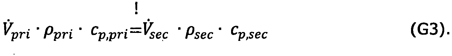
Für die Volumenstromregelung der primärseitigen Kreiselpumpe 17 wird ihr aktueller Förderström V̇pri,ist als Istwert verwendet. Dieser kann innerhalb oder außerhalb der Kreiselpumpe 17 entweder direkt gemessen werden, beispielsweise mittels einem Volumenstromsensor, oder aus anderen physikalischen Größen berechnet werden oder geschätzt werden. Eine Berechnung kann beispielsweise aus dem von der Pumpe erzeugten Differenzdruck und der Pumpendrehzah. Eine Schätzung kann anhand von Modellgleichungen für das mechanisch-hydraulische Pumpen-Motormodell gegebenenfalls unter berücksichtigen des elektrisch-mechanischen Motormodells erfolgen, wie dies üblicherweise bei regelungstechnischen Beobachtern der Fall ist.For the volume flow control of the primary
Daher wird Gleichung G3 nach dem primärseitigen Volumenstrom V̇pri umgestellt.Therefore, equation G3 is converted to the primary-side volume flow V̇ pri .
Denn für den entsprechenden Sollwert der Volumenstromregelung V̇pri,soll gilt dann: 
Daraus wird ersichtlich, dass sich bei Mediengleichheit auf Primär- 2 und Sekundärseite 4 der Übergabestelle 3 die Forderung nach der Gleichheit der Volumenströme ergibt, d.h. V̇pri,soll = V̇sec gilt. Bei Medienverschiedenheit ist allerdings der sekundärseitige Gesamtvolumenstrom V̇sec mit einem Faktor k zu gewichten, der das Produkt aus den Dichteverhältnisse und Wärmekapazitätsverhältnissen beschreibt. Es gilt dann ![]()
![]()
![]()
![]()
Nun ist zu berücksichtigen, dass gemäß 
Die Verbraucherkreisvolumenströme V̇ sec,1, V̇ sec,2 , ..., V̇sec,n können innerhalb oder außerhalb der Verbraucherkreispumpen 12 entweder direkt gemessen, berechnet oder geschätzt werden, wie dies oben zur primärseitigen Kreiselpumpe ausgeführt wurde.The consumer circuit volume flows V̇ sec, 1 , V̇ sec, 2 , ..., V̇ sec, n can either be measured, calculated or estimated directly inside or outside the consumer circuit pumps 12, as was explained above for the primary centrifugal pump.
Vor diesem Hintergrund ist die Kernidee des erfindungsgemäßen Verfahrens, die primärseitige Kreiselpumpe 17 so zu regeln, dass ihr Förderstrom dem mit dem Faktor k gewichteten Summe der Verbraucherkreisvolumenströme, insbesondere der im Sekundärkreis 4 strömungstechnisch parallel liegenden Verbraucherkreispumpen 12 entspricht gegebenenfalls multipliziert mit dem vorbestimmten Verhältniswert a und/ oder addiert mit dem vorgegebenen Offset b, wobei insbesondere im Falle von Mediengleichheit der Faktor k = 1 ist.Against this background, the core idea of the method according to the invention is to regulate the primary-side
Die Verbraucherkreisvolumenströme V̇ sec,1, V̇ sec,2, ..., V̇sec,n können von unabhängigen Volumenstrommesseinrichtungen oder von Volumenstromsensoren innerhalb der Verbraucherkreispumpen 12 ermittelt werden. Unabhängige Volumenstrommesseinrichtungen haben den Vorteil, dass sie an einer beliebigen Stelle innerhalb eines Verbraucherkreises 5 installiert werden können. Dies ist insbesondere dann von Vorteil, wenn Rezirkulationen im Verbraucherkreis 5 vorliegen und die Verbraucherkreispumpen 12 den Volumenstrom durch die Verbraucher 6 , nicht jedoch den hierzu geringeren Verbraucherkreisvolumenstrom fördern, was nachfolgend noch veranschaulicht wird.The consumer circuit volume flows V̇ sec, 1 , V̇ sec, 2 , ..., V̇ sec, n can be determined by independent volume flow measuring devices or by volume flow sensors within the consumer circuit pumps 12. Independent volume flow measuring devices have the advantage that they can be installed at any point within a
Demgegenüber hat jedoch eine Ermittlung der Verbraucherkreisvolumenströme durch die Verbraucherkreispumpen den Vorteil, dass auf zusätzliche externe Messtechnik zur Volumenstrommessung in den Verbraucherkreisen verzichtet werden kann. Somit entfällt auch die Notwendigkeit, zusätzliche Stromversorgungen für eine solche externe Messtechnik sowie zusätzliche Kommunikationsleitungen zur Übertragung der Messdaten vorzusehen, wodurch der Installations-, Wartungs- und Kostenaufwand minimal ist. Moderne elektronisch geregelte Umwälzpumpenaggregate ermitteln in der Regel für ihre Regelung, für eine Betriebspunkterkennung und/ oder für sonstige Zusatzfunktionen wie Fehleranalysen den Förderstrom Q, so dass hier eine entsprechende Messtechnik und/ oder softwaretechnische Ermittlungsverfahren bereits in der Pumpenelektronik vorhanden sind. Idealerweise können solche Pumpenaggregate mit integrierter Volumenstromermittlung als Verbraucherkreispumpen 12 verwendet werden.In contrast, however, determining the consumer circuit volume flows by the consumer circuit pumps has the advantage that additional external measurement technology for volume flow measurement in the consumer circuits can be dispensed with. This also eliminates the need to provide additional power supplies for such external measurement technology and additional communication lines for the transmission of the measurement data, whereby the installation, maintenance and cost outlay is minimal. Modern electronically controlled circulating pump units usually determine the flow rate Q for their control, for operating point detection and / or for other additional functions such as error analyzes, so that a corresponding measurement technology and / or software-based determination process is already available in the pump electronics. Ideally, such pump units with integrated volume flow determination can be used as consumer circuit pumps 12.
Des Weiteren ist es von Vorteil, wenn die zu regelnde Kreiselpumpe 17 den Sollwert für Ihre Volumenstromregelung in ihrer Pumpenelektronik auf der Grundlage der Verbraucherkreisvolumenströme V̇ sec,1 selbsttätig ermittelt. Hierzu werden die ermittelten Verbraucherkreisvolumenströme V̇ sec,1 an die zu regelnde Kreiselpumpe kommuniziert. In dieser Ausführungsvariante ist dann in der Pumpenelektronik der primärseitigen Kreiselpumpe 17 eine Auswerteeinheit integriert, die aus den Verbraucherkreisvolumenströmen V̇ sec,1 , V̇ sec,2 , ..., V̇sec,n den primärseitigen Sollvolumenstrom V̇pri,soll gemäß Gleichungen G5 und G6 bei gegebenenfalls vorgegebenen Faktor k berechnet, sofern keine Mediengleichheit vorliegt. In der Pumpenelektronik der zu regelnden Pumpe 17 kann dieser Faktor k jedoch auch standardmäßig mit k = 1 vorbelegt sein, so dass bei der Inbetriebnahme im Falle von Mediengleichheit beidseits der Übergabestelle 3 keine weitere Einstellung bzw. Vorgabe für k erfolgen muss.Furthermore, it is advantageous if the
Die Übertragung der Verbraucherkreisvolumenströme V̇ sec,1 kann vorteilhafterweise von der jeweiligen Messstelle direkt an die primärseitige Kreiselpumpe erfolgen, d.h. beispielsweise von den unabhängigen Volumenstrommesseinrichtungen oder von den einzelnen Verbraucherkreispumpen 12.The consumer circuit volume flows V̇ sec, 1 can advantageously be transmitted from the respective measuring point directly to the primary-side centrifugal pump, ie, for example, from the independent volume flow measuring devices or from the individual consumer circuit pumps 12.
Gemäß einer alternativen Variante kann die Ermittlung des Sollvolumenstroms V̇pri,soll gemäß Gleichungen G5 und G6 aus den Verbraucherkreisvolumenströmen V̇sec,i auch in einer externen Auswerteeinheit 28 erfolgen, beispielsweise in einer zentralen Kommunikationseinrichtung 28, die einerseits in Kommunikationsverbindung mit den Verbraucherkreispumpen 12 steht, um die ermittelten Verbraucherkreisvolumenströme V̇ sec,1 von diesen zu erhalten oder anzufordern, andererseits mit der zu regelnden primärseitigen Pumpe 17 in Kommunikationsverbindung steht, um dieser den ermittelten Sollvolumenstrom V̇pri,soll zu übermitteln. Für eine eventuelle Vorgabe des Gewichtungsfaktors k der externen Auswerteeinheit gilt das zuvor Gesagte analog.According to an alternative variant, the setpoint volume flow V̇ pri, should according to equations G5 and G6 from the consumer circuit volume flows V̇ sec, i can also be determined in an
Zur Datenübertragung weisen die Volumenstrommesseinrichtungen und/ oder Verbraucherkreispumpen 12 geeignete Kommunikationsschnittstellen auf, um die Verbraucherkreisvolumenstromdaten zu übertragen. Moderne Pumpenaggregate verfügen heutzutage bereits über Kommunikationsschnittstellen wie CAN. LON. BACnet, Modbus, LAN etc, so dass keine zusätzliche Kommunikationseinheiten erforderlich, um die Volumenstromdaten an die zu regelnde Pumpe zu übertragen. Auch sind Funkmodule bei Pumpenaggregaten hinlänglich bekannt. In den Figuren ist eine kabelgebundene Kommunikation mittels Datenleitungen 20 veranschaulicht, die an das Datennetzwerk 19 angeschlossen sind, an welches auch die primärseitige Kreiselpumpe 17 angeschlossen ist.For data transmission, the volume flow measuring devices and / or consumer circuit pumps 12 have suitable communication interfaces in order to transmit the consumer circuit volume flow data. Modern pump units nowadays already have communication interfaces such as CAN. LON. BACnet, Modbus, LAN etc, so that no additional communication units are required to transmit the volume flow data to the pump to be controlled. Radio modules for pump units are also well known. The figures illustrate wired communication by means of
Wie bereits erwähnt, gibt es Heizungs- und Kühlanlagen, bei denen ein Verbraucherkreisvolumenstrom V̇ sec,1 nicht mit dem Verbrauchervolumenstrom V̇consumer,i der in dem entsprechenden Verbraucherkreis angeordneten Verbraucherkreispumpe 12 identisch ist. So ist es in der Heizungstechnik beispielsweise üblich, jedem oder einzelnen Verbraucherkreisen 5a durch Beimischen von Rücklaufflüssigkeit der lokalen Rücklaufleitung 9 eine individuell verringerte Vorlauftemperatur bereitzustellen. Dies ist zum Beispiel bei Fussbodenheizungen der Fall. Wie in
Durch die Verwendung eines Mischers 11 in einem Verbraucherkreis 5a zum Zumischen lokaler Rücklaufflüssigkeit in den lokalen Vorlauf 10 ist die Summe der von den Verbraucherkreispumpen 12 geförderten Volumenströme größer als der von der Übergabestelle 3 bereitgestellte bzw. zur Übergabestelle 3 rückfließende Volumenstrom V̇sec. By using a
Dies ist unproblematisch, sofern ein Verbraucherkreisvolumenstrom V̇sec,i in Strömungsrichtung vor dem Mischer 11 in der lokalen Vorlaufleitung 10 oder in der lokalen Rücklaufleitung 9 hinter dem Abzweig in die Mischleitung 22 ermittelt wird. Dies ist mit einer pumpenunabhängigen Volumenstrommesseinrichtung grundsätzlich möglich, da sie an jedem beliebigen Ort im Verbraucherkreis 5a angeordnet werden kann. Soll jedoch die Verbraucherkreisvolumenstromermittlung durch die Verbraucherkreispumpen 12 erfolgen, weil sie ohnehin über die hierfür notwendigen Mittel verfügt, so ist dies nicht unmittelbar möglich, wenn die Verbraucherkreispumpen , wenn in Strömungsrichtung hinter dem Mischer 11 oder besagtem Abzweig liegen, wie dies in
So kann gemäß einer vorteilhaften Weiterbildung des erfindungsgemäßen Verfahrens eine Korrektur jedes von den Verbraucherkreispumpen 12 ermittelten Volumenstroms V̇consumer,i durch Multiplikation mit einem verbraucherkreisspezifischen Korrekturwert Ci erfolgen. Dieser Korrekturwert Ci ist vorzugsweise gebildet durch das Verhältnis aus der Temperaturdifferenz zwischen dem lokalen Vorlauf 10 hinter dem Mischer 11 und dem lokalen Rücklauf 9 des entsprechenden Verbraucherkreises 5a zur Temperaturdifferenz zwischen dem zentralen sekundärseitigen Vorlauf 7 und dem lokalen Rücklauf 9 des entsprechenden Verbraucherkreises 5a. Alternativ kann anstelle der zentralen sekundärseitigen Vorlauftemperatur die primärseitige Vorlauftemperatur verwendet werden. Dies hat den Vorteil, dass keine zusätzliche Messtechnik zur Messung der sekundärseitigen Vorlauftemperatur erforderlich ist. Vielmehr kann auf Messtechnik für die Erfassung der Temperaturen zurückgegriffen werden, die in den Kreiselpumpen integriert oder zumindest teilintegriert ist.Thus, according to an advantageous development of the method according to the invention, each volume flow V Volumen consumer, i determined by the consumer circuit pumps 12 can be corrected by multiplication by a consumer circuit-specific correction value C i . This correction value C i is preferably formed by the ratio of the temperature difference between the
So können also geeigneterweise die Temperaturen im lokalen Vorlauf 10 des Verbraucherkreises 5a hinter dem Mischer 11, im lokalen Rücklauf 8 sowie im primären Vorlauf 15 gemessen und zur Berechnung des Korrekturwerts Ci für diesen Verbraucherkreis 5a gemäß zuvor genanntem Verhältnis verwendet werden. Die Ermittlung der Temperatur im lokalen Vorlauf 7 kann mittels eines ersten Temperatursensors 31, 33 (siehe
Gemäß der Ausführungsvariante in
Gemäß einer alternativen Ausführungsvariante können die Temperatursensoren aber auch eigene Kommunikationsschnittstelle mit entsprechender Kommunikationsfähigkeit aufweisen, und an das Datennetzwerk 19 per Funk oder Kabel angeschlossen sein. Dies ermöglicht eine direkte Zuleitung der Temperaturmesswerte an die zu regelnde Pumpe 17, so dass bezüglich der Datenübertragung kein Umweg über die Verbraucherkreispumpen 12 erfolgen muss.According to an alternative embodiment variant, however, the temperature sensors can also have their own communication interface with a corresponding communication capability and can be connected to the
In gleicher Weise kann gemäß der Ausführungsvariante in
Die zu regelnde primärseitige Pumpe 17 erhält somit Messwerte von allen drei Temperatursensoren 24, 31, 32 bzw. 24, 33, 34 und kann den verbraucherkreisspezifischen Korrekturwert Ci berechnen, indem die Differenz aus der lokalen Vorlauf- und Rücklauftemperatur durch die Differenz aus der zentralen Vorlauf- und der lokalen Rücklauftemperatur geteilt wird.The primary-
Es sei angemerkt, dass nicht unbedingt die zu regelnde, primärseitige Pumpe 17 die Berechnung des Korrekturwerts Ci durchführen muss. Dies kann vielmehr auch in einer der Verbraucherpumpen erfolgen, damit diese den korrekten Verbraucherkreisvolumenstrom bereitstellen. In diesem Fall müssen die Temperaturmesswerte an die entsprechende Verbraucherkreispumpe 12 übertragen werden, d.h. die zentrale Vorlauftemperatur an alle Verbraucherkreispumpen 12. Dies kann kabelgebunden über das Datennetzwerk 19 oder per Funk erfolgen. Ferner kann es von der zu regelnden Pumpe 17 oder von dem dritten Temperatursensor durchgeführt werden.It should be noted that the primary-
Gemäß einer weiteren Alternative kann die Berechnung des Korrekturwerts Ci in der zentralen Auswerteeinheit erfolgen, die den Sollvolumenstrom für die zu regelnde primärseitige Pumpe bereitstellt. Entsprechend den vorgenannten Möglichkeiten sind dann die Temperaturmesswerte an diese zentrale Auswerteeinheit zu übertragen.According to a further alternative, the calculation of the correction value C i can take place in the central evaluation unit which provides the setpoint volume flow for the primary-side pump to be regulated. In accordance with the aforementioned options, the measured temperature values are then to be transmitted to this central evaluation unit.
Die Temperaturmessung im lokalen Vorlauf 10, lokalen Rücklauf 9 des Verbraucherkreises 5a und des primären Vorlaufs 15 hat den Vorteil, dass auf in den Pumpen vorhandene Messtechnik weitestgehend zurückgegriffen werden kann, d.h. auf zusätzliche, autarke externe Temperaturmesstechnik grundsätzlich verzichtet werden kann, um den jeweiligen Korrekturwert Ci zu ermitteln. Denn idealerweise entspricht die jeweilige Medientemperatur der Vorlauftemperatur, jedenfalls sofern sich die entsprechende Pumpe im Vorlauf befindet. Ist die Verbraucherkreispumpe 12 in den lokalen Vorlauf 10 integriert, ermittelt sie entsprechend die Vorlauftemperatur. Ist sie in den Rücklauf 9 integriert, misst sie entsprechend die Rücklauftemperatur. Der an die jeweilige Verbraucherkreispumpe 12 angeschlossene zweite Temperaturfühler 34 ist dann in dem entsprechend anderen Strömungsweg zu integrieren.The temperature measurement in the
Wird anstelle der primärseitigen Vorlauftemperatur die zentrale sekundärseitige Vorlauftemperatur zur Ermittlung des Korrekturwerts Ci verwendet, ist der dritte Temperatursensor in dem zentralen sekundärseitigen Vorlauf 7 anzuordnen. Allerdings ist die kommunikationstechnische Anbindung in diesem Fall gegebenenfalls schwierig, weil die zu regelnde primärseitige Pumpe 17 und die Verbraucherkreispumpe bei sich weit erstreckenden Heizungsanlagen 1 weit weg von der Messstelle im zentralen sekundären Vorlauf 7 sein können. Daher ist es hier von Vorteil, den dritten Temperatursensor mit einer eigenen Kommunikationseinheit auszustatten und ihn mit dem Datennetzwerk 19 zu verbinden.If, instead of the primary-side supply temperature, the central secondary-side supply temperature is used to determine the correction value C i , the third temperature sensor is to be arranged in the central secondary-
Der Gedanke hinter der Ermittlung des Korrekturwerts Ci wird nachfolgend veranschaulicht.The idea behind the determination of the correction value C i is illustrated below.
Da sich der Wärmestrom Q̇ über dem Mischer 11 nicht ändert, d.h. Q̇sec,i = Q̇consumer,i, kann aus den Temperaturdifferenzen (Spreizung) vor und nach dem Mischer 11 der Korrekturwert Ci ermittelt werden, mittels welchem dann aus dem Verbrauchervolumenstrom V̇ consumer,i hinter dem Mischer 11 der Verbraucherkreisvolumenstrom V̇sec,i vor dem Mischer 11 berechnet werden kann. Der Korrekturwert Ci kann dem Verhältnis der genannten Temperaturdifferenzen entsprechen. Es gilt dann gemäß Gleichung 7: ![]()
- V̇sec,i
- der in den i-ten
Verbraucherkreis 5a hineinfließende Verbraucherkreisvolumenstrom (Volumenstrom vor dem Mischer 11), - V̇ consumer,i
- der in dem i-ten
Verbraucherkreis 5a durch den oder dieVerbraucher 6 fließende Verbrauchervolumenstrom (Volumenstrom hinter dem Mischer 11), - ΔTconsumer,i
- die Temperaturdifferenz zwischen Vor- 10 und Rücklauf 9 nach
dem Mischer 11 im i-ten Verbraucherkreis, und - ΔTsec,i
- die Temperaturdifferenz zwischen Vor- 10 und Rücklauf 9
vor dem Mischer 11 im i-ten Verbraucherkreis ist.
- V̇ sec, i
- the consumer circuit volume flow flowing into the i-
th consumer circuit 5a (volume flow upstream of the mixer 11), - V̇ c onsumer, i
- the consumer volume flow flowing in the i-
th consumer circuit 5a through the consumer or consumers 6 (volume flow behind the mixer 11), - Δ T consumer, i
- the temperature difference between
flow 10 andreturn 9 after themixer 11 in the i-th consumer circuit, and - Δ T sec, i
- is the temperature difference between
flow 10 andreturn 9 upstream ofmixer 11 in the i-th consumer circuit.
Um den Korrekturfaktor Ci zu bestimmen, kann eine Temperaturmessung an vier Punkten des Verbraucherkreislaufs 5a erfolgen, nämlich vor (TVL,sec,i) und nach (TVL,consumer,i) dem Mischer 11 in der lokalen Vorlaufleitung 10 und vor (TRL,consumer,i) und nach (TRL,sec,i) dem Abzweig zum Bypass 22 in der lokalen Rücklaufleitung 9, so dass dann gilt: 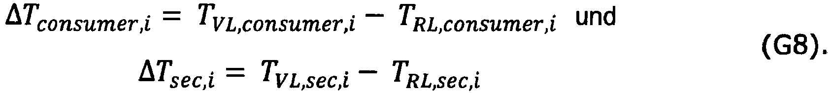
Für die Berechnung des Korrekturfaktors C können aber auch folgende Erkenntnisse herangezogen werden, deren Beachtung den messtechnischen Aufwand reduziert:
Zum einen gilt für die Temperaturdifferenz ΔTsec,i vor dem Mischer 11 dieselbe Rücklauftemperatur, wie für die Temperaturdifferenz ΔTconsumer,i hinter dem Mischer 11, TRL,consumer,i = TRL,sec,i, da sich die Temperatur durch den Abzweig der lokalen Rücklaufleitung 9 in die Mischleitung 22 nicht ändert. Somit genügt eine einzige Temperaturmessung in der lokalen Rücklaufleitung 9, was allerdings für jeden Verbraucherkreis 5a mit Vorlaufmischer 11 erfolgen muss.For the calculation of the correction factor C, however, the following findings can also be used, the observance of which reduces the measurement effort:
On the one hand, the same return temperature applies to the temperature difference Δ T sec, i upstream of the
Zum anderen ist die Vorlauftemperatur TVL,sec,i vor dem Mischer 11 für alle Verbraucherkreise 5a gleich, so dass anstelle verbraucherkreisbezogener Temperaturmessungen in den lokalen Vorläufen 10 vor den Mischern 11, die zentrale Vorlauftemperatur TVL,sec herangezogen werden kann, 
Unter Berücksichtigung dieser Zusammenhänge kann der verbraucherkreisspezifische Korrekturwert Ci wie folgt ermittelt werden: 
Bei der Verwendung einer hydraulischen Weiche 3b oder eines druckarmen Verteilers 3c als Übergabestelle 3 kann ferner unter der Annahme idealisierter Verhältnisse angenommen werden, dass die Vorlauftemperatur über die Weiche 3b bzw. den Verteiler 3c gleich bleibt, zumindest sofern und solange der Primärmassestrom V̇pri größer oder gleich dem Sekundärmassestrom V̇sec ist. Es gilt dann TVL,sec = TVL,pri . Mit dieser Annahme kann anstelle der sekundärseitigen Vorlauftemperatur TVL,sec die primärseitige Vorlauftemperatur verwendet werden. Dies hat den Vorteil, dass keine zusätzliche Messtechnik im sekundärseitigen Vorlauf zur Temperaturmessung angeordnet werden muss, sondern geeigneterweise die zu regelnde primärseitige Pumpe 17 mit einer Temperaturmesswerte verarbeitenden Pumpenelektronik ausgestattet ist, wie dies bereits heute bei modernen Kreiselpumpen der Fall ist. Diese kann dann die Aufgabe der Messelektronik übernehmen und eine Auswertung vornehmen. Ist die zu regelnde Kreiselpumpe 17 zusätzlich im Vorlauf des Primärkreises angeordnet, kann anstelle eines externen Temperaturfühlers ein pumpenintegrierter Temperatursensor verwendet werden, der die Medientemperatur ermittelt.When using a
Unter Berücksichtigung der getroffenen Annahmen ergibt sich der sekundärseitige Summenvolumenstrom V̇sec aus der Addition der korrigierten Verbrauchervolumenströme V̇consumer,i , wobei die Korrektur jedoch nur dort stattfinden muss, wo Mischer 11 in den Verbraucherkreisen 5a sind. ![]()

![]()
Somit erfolgt die Berechnung des primären Sollvolumenstroms vorzugsweise anhand Gleichungen G5 und G11a und b.Thus, the calculation of the primary target volume flow is preferably carried out using equations G5 and G11a and b.
Im Falles des in ![]()
![]()
Soll die idealisierte Betrachtung der Übergabestelle 3 durch eine realitätsgetreue Betrachtung ersetzt werden, ist eine Temperaturabfall ΔTpri-sec zwischen dem primärseitigen Vorlauf 15 und dem sekundärseitigen zentralen Vorlauf 7 zu berücksichtigen: ![]()
![]()
So kann in einer erfindungsgemäßen Weiterbildung des Verfahrens die Berechnung des verbraucherkreisspezifischen Korrekturwerts Ci in G11b ersetzt werden durch G14: 
Denn bei realen, großzügig dimensionierten hydraulischen Weichen 3b findet bei Volumenstromabgleich eine Durchmischung in der Weiche 3b statt, bei der im Vorlauf wie auch im Rücklauf die Temperatur von der Primär- zur Sekundärseite um den gleichen Betrag abfällt. Analog dazu ist die treibende Temperaturdifferenz beim Wärmetauscher 3a sowie beim verlustarmen Verteiler 3c.Because with real, generously dimensioned
Wird der Temperaturabfall nicht berücksichtigt, so ergibt sich nach Gleichung 11 ein zu geringer Wert für den Sekundärvolumenstrom V̇sec, weil die Spreizung überschätzt wird. Daher würde auch ein zu geringer Primärvolumenstrom V̇pri eingeregelt. In der hydraulischen Weiche 3b würde dann die Temperatur durch den größeren Sekundärvolumenstrom heruntergemischt werden und es kommt zu einer Unterversorgung der Verbraucher 6.If the temperature drop is not taken into account, then according to
Oftmals ist auch bei mindestens einem Heizkreis kein Mischer installiert, so dass der Temperaturabfall ständig gemessen werden kann.Often no mixer is installed in at least one heating circuit so that the temperature drop can be measured continuously.
Der Temperaturabfall ΔTpri-sec wird vorzugsweise dadurch ermittelt, dass in einem mischerlosen Verbraucherkreis 5b (![]()
![]()
Denn bei einem mischerlosen Verbraucherkreis 5b ist die Sekundärvorlauftemperatur TVL.sec gleich der Temperatur TVL.sec,i im lokalen Vorlauf 10 des Verbraucherkreises 5a: TVL.sec = TVL,sec,i, so dass es nicht erforderlich ist, diese Sekundärvorlauftemperatur TVL.sec zu messen. Vielmehr kann die ohnehin vorhandene Messstelle hierzu verwendet werden. Das heißt, dass bei einem mischerlosen Verbraucherkreis 5b, wie er in
Alternativ oder zusätzlich kann der Temperaturabfall ΔTpri-sec bei einem Rücklaufmedium in den Vorlauf mischenden Verbraucherkreis 5a ermittelt werden, indem bei voll geöffnetem Mischer 11, d.h. bei fehlender Zumischung von Rücklaufmedium in den lokalen Vorlauf, die Differenz zwischen der primären Vorlauftemperatur TVL.pri und der sekundären lokalen Vorlauftemperatur TVL.consumer,i hinter dem Mischer 11 in diesem Verbraucherkreis 5a berechnet wird: ![]()
![]()
Denn bei einem voll geöffnetem Mischer 11 liegt die Sekundärvorlauftemperatur TVL.sec an der Messstelle im lokalen Vorlauf 10 des Verbraucherkreises 5a hinter dem Mischer 11 an TVL.sec = TVL.consumer,i,open valve, so dass es nicht erforderlich ist, diese Sekundärvorlauftemperatur TVL.sec zu messen, sondern die ohnehin vorhandene Messstelle hierzu verwendet werden kann. Das heißt, sobald ein Mischer 11 voll geöffnet ist, kann der Temperaturabfall ΔTpri-sec über der Übergabestelle 3 im Vorlauf 15, 10 gemessen werden.Because with a fully
Dies muss jedoch nicht fortwährend erfolgen. Es genügt, wenn der Temperaturabfall ΔTpri-sec zumindest ein Mal berechnet und abgespeichert wird. Da diese Berechnung auf Messwerten beruht, die ohnehin gemeinsam an einer der Auswertungsstellen vorliegen, d.h. vorzugsweise in der zu regelnden primären Kreiselpumpe 17, alternativ in der jeweiligen Verbraucherkreispumpe 12 oder in der zentralen Auswertungseinheit, wird dort lediglich noch die Information benötigt, wann der Mischer voll geöffnet ist. Liegt diese Information vor, wird Temperaturabfall ΔTpri-sec aus der Differenz der dann vorliegenden Vorlauftemperaturen T VL.pri und TVL.consumer,i berechnet.However, this does not have to be done continuously. It is sufficient if the temperature drop Δ T pri-sec is calculated and stored at least once. Since this calculation is based on measured values that are already available together at one of the evaluation points, i.e. preferably in the primary
Die Bereitstellung der Information kann beispielsweise über ein entsprechendes Öffnungssignal vom Mischer 11 erfolgen. Das Öffnungssignal kann kabelgebunden oder per Funk zu der entsprechenden Auswertungsstelle übertragen werden. Hierzu kann eine entsprechende Meldeleitung zwischen Auswertungsstelle und Mischer 11 bestehen, oder der Mischer 11 verfügt über eine Kommunikationseinheit, die seine Anbindung an das Datennetzwerk 19 ermöglicht.The information can be provided, for example, via a corresponding opening signal from the
Vorzugsweise erfolgt die Ermittlung des Temperaturabfalls ΔTpri-sec wiederholt in zeitlichen Abständen, insbesondere immer wieder, wenn ein Mischer 11 voll geöffnet ist. Dies hat den Vorteil, dass Korrekturen und Mittelwertbildungen des Temperaturabfalls ΔTpri-sec möglich sind.The temperature drop Δ T pri-sec is preferably determined repeatedly at time intervals, in particular again and again when a
An dieser Stelle sei noch ergänzt, dass ein Einsetzen von G15 in G14 zu einem Korrekturwert Ci = 1 führt, d.h. bei voll geöffnetem Mischer mathematisch keine Korrektur des ermittelten Verbrauchervolumenstroms V̇consumer,i erforderlich ist, weil er dem Verbraucherkreisvolumenstrom V̇sec,i entspricht. Entsprechend ist in G11 für n=3 entsprechend
Da der Temperaturabfall ΔTpri-sec über dem Vorlauf betraglich identisch ist wie der Temperaturabfall über dem Rücklauf, kann gemäß einer alternativen Ausführungsvariante der Temperaturabfall ΔTpri-sec anstelle im Vorlauf im Rücklauf bestimmt werden. Denn es gilt analog zu Gleichung 15: ![]()
![]()
Hierfür ist jedoch mittels einem vierten Temperatursensor 26 die primärseitige Rücklauftemperatur TRL,pri zusätzlich zu messen. Die zentrale sekundärseitige Rücklauftemperatur TRL,sec im Sekundärkreis 4 kann entsprechend der Mischungsregel 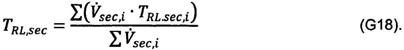
Erfindungsgemäß wird nun auch die Rücklauftemperatur TRL.pri im Primärkreis 2 gemessen, so dass all Größen in Gleichung G17 bekannt sind und diese zur Berechnung des Temperaturabfalls verwendet werden kann. According to the invention, the return temperature T RL.pri is now also measured in the
Wird als Übergabestelle 3 ein Wärmetauscher 3a verwendet, so können sich die im Primärkreis 2 und Sekundärkreis 4 zirkulierenden Medien unterscheiden. Gemäß Gleichung G5 ist bei dieser Medienverschiedenheit der Gewichtungsfaktor k ungleich 1. Da das zu verwendeten Heiz-/Kühlmedium oder die Medien beim Entwurf der Heizungs- oder Kühlanlage festgelegt wird/ werden, sind auch seine/ ihre Dichte(n) und spezifischen Wärmekapazität(en) grundsätzlich bekannt und können der Volumenstromregelung der primärseitigen Pumpe 17 als solche oder in Gestalt des bereits nach Gleichung G5 berechneten Gewichtungsfaktors k vorgegeben werden.If a
Alternativ hierzu kann erfindungsgemäß auch eine automatische Ermittlung des Gewichtungsfaktors k erfolgen. Da die Wärmeströme auf der Primär- und Sekundärseite gleich sein müssen (adiabate Übergabe) folgt aus Gleichung G1: 
Dabei wird die Temperaturspreizung ΔTpri und der Volumenstrom V̇pri auf der Primärseite 2 der Übergabestelle 3 ermittelt, insbesondere gemessen, wie dies zuvor bereits ausführlich unter Verweis auf die verschiedenen Möglichkeiten beschrieben worden ist. So kann der primärseitige Volumenstrom V̇pri vorzugsweise von einem in die zu regelnde Pumpe 17 integrierten Volumenstromsensor oder aus anderen Größen innerhalb der Pumpe 17 rechnerisch ermittelt werden. Zur Bestimmung der Temperaturspreizungen können der dritte 24 und vierte 26 Temperatursensor dienen, wobei vorzugsweise die Pumpenelektronik der zu regelnden primärseitigen Pumpe 17 die Differenz aus diesen Sensorwerten ermittelt.The temperature spread Δ T pri and the volume flow V̇ pri on the
Der Volumenstrom V̇sec auf der Sekundärseite 4 kann erfindungsgemäß nach einer der zuvor beschriebenen Gleichungen G6, G7 oder G11a berechnet werden.The volume flow V̇ sec on the
Darüber hinaus kann auch die Spreizung ΔTsec auf der Sekundärseite 4, d.h. die Differenz zwischen der sekundärseitigen Vorlauftemperatur TVL,sec und der sekundärseitigen Rücklauftemperatur TRL,sec berechnet werden. ![]()
![]()
Die sekundärseitige Rücklauftemperatur TRL,sec wird dabei vorzugsweise aus der Mischungsregel nach Gleichung G18 bestimmt. Die sekundärseitige Vorlauftemperatur TVL,sec kann aus der primärseitigen Vorlauftemperatur TVL,pri und dem Temperaturabfall ΔT pri-sec über der Übergabestelle 3 berechnet werden: ![]()
![]()
Da die primärseitige Vorlauftemperatur TVL,pri, wie zuvor beschrieben, auch für die primärseitige Temperaturspreizung ΔTsec benötigt wird, liegt sie an dieser Stelle bereits vor und kann verwendet werden. Der Temperaturabfall ΔTpri-sec kann auf einem der oben beschriebenen Wege mittels einer der Gleichungen 15 oder 16 oder 17 und 18 bestimmt werden.Since the primary-side flow temperature T VL, pri , as described above, is also required for the primary-side temperature spread Δ T sec , it is already available at this point and can be used. The temperature drop Δ T pri-sec can be determined in one of the ways described above using one of
Die vollständige Berechnungsvorschrift für den Gewichtungsfaktor k erhält man dann bei Berücksichtigung einer realen Übergabestelle (d.h. mit Temperaturabfall) und mit Mischerbehafteten Verbraucherkreisen 5a durch Einsetzen beispielsweise der Gleichungen G11a mit G14 und G16, und G21 mit G22, G18 und G16 in Gleichung G19: ![]()
![]()
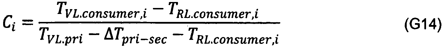
![]()

![]()
![]()
![]()
![]()
![]()
Auf eine geschachtelte Darstellung der Berechnungsvorschrift für den Gewichtungsfaktor k wird an dieser Stelle aus Gründen der Übersichtlichkeit und Lesbarkeit verzichtet. Gleichwohl kann die Berechnungsvorschrift als mathematisch in sich geschlossener Ausdruck dargestellt und berechnet werden.A nested representation of the calculation rule for the weighting factor k is dispensed with at this point for reasons of clarity and legibility. Nevertheless, the calculation rule can be represented and calculated as a mathematically self-contained expression.
Mit dem auf diese Weise softwaretechnisch bestimmbaren Faktor k kann dann der bei der primärseitigen Kreiselpumpe 17 einzuregelnde Soll-Volumenstrom V̇pri,soll nach Gleichung 5 berechnet werden und entsprechend in der Pumpenregelung eingestellt werden.With the factor k, which can be determined by software in this way, the set volume flow V̇ pri to be regulated in the primary-side
Die in
Gemäß einer in
Jedem Erzeugerkreis 14a, 14b ist eine Erzeugerpumpe 17a, 17b zugeordnet, die das Heizmedium im jeweiligen lokalen Vorlauf 20 antreibt und in den zentralen Vorlauf 15 fördert. Bei Heizungsanlage 1 dieser Art ist es nicht erforderlich, alle Erzeugerpumpen 17a, 17b zu regeln, bzw. identisch zu regeln. Vielmehr kann mit einem einzigen der Erzeugerkreise 14b die variierende, bedarfsweise anfallende Spitzenlast gedeckt und mit den übrigen Erzeugerkreisen 14a die Grundlast erbracht werden. Die Erzeuger 18 in diesen Kreisen 14a laufen mit maximaler thermischer Leistung. Entsprechendes gilt für deren Grundlastpumpen 17a. Nur die Pumpe 17b für den Spitzenlast-Erzeugerkreis 14b passt sich an die Schwankungen im verbraucherseitigen Volumenstrom an, um eine energieeffiziente Heizungspumpenregelung zu erreichen. Daher muss das erfindungsgemäße Verfahren auch nur auf diese Spitzenlastpumpe 17b angewendet werden, während die Grundlastpumpen 17a nicht oder anders geregelt sind.A
Der Erzeuger 18 in dem Spitzenlast-Erzeugerkreis 14b moduliert seine thermische Leistung entsprechend der gewünschten zentralen primärseitigen Vorlauftemperatur TVL,pri oder der zentralen sekundärseitigen Vorlauftemperatur TVL,sec, wobei sich die Spitzenlastpumpe 17b anpasst. Erreicht die thermische Leistung dabei eine Stellgrenze, ohne dass die gewünschte Vorlauftemperatur TVL,pri oder TVL,sec erreicht wird, muss ein Grundlast-Erzeugerkreis 14a einschließlich des oder der zugehörigen Erzeuger(s) und der zugehörigen Grundlastpumpe 17a abgeschaltet oder zugeschaltet werden.The
Gemäß einer Ausführungsvariante des erfindungsgemäßen Verfahrens wird nun diejenige Erzeugerpumpe 17b, die dem eine Spitzenlast bedienenden Erzeugerkreis 14b zugeordnet ist, derart geregelt, dass der gesamte Volumenstrom V̇pri auf der Primärseite 2 dem Volumenstrom V̇sec auf der Sekundärseite 4 entspricht. Dies bedeutet, dass auch der Volumenstrom, der von der oder den Erzeugerpumpe(n) 17a, die einem eine Grundlast bedienenden Erzeugerkreis 14a zugeordnet ist/ sind, berücksichtigt werden muss. Die dem Spitzenlast bedienenden Erzeugerkreis 14b zugeordne Pumpe wird deshalb im Sinne der Erfindung auch Spitzenlastpumpe 17b, die dem oder den die Grundlast bedienenden Erzeugerkreis(en) 14a zugeordnete Pumpe oder Pumpen 17a werden Grudlastpumpen genannt.According to one embodiment of the method according to the invention, that
Wird davon ausgegangen, dass eine Anzahl m Erzeugerkreise 14a, 14b vorhanden sind, denen der p-te Erzeugerkreis 14b die Spitzenlast bedient, die übrigen Erzeugerkreise die Grundlast, ergibt sich analog Gleichung G1: 
Geeigneterweise stellt, wie bei den vorherigen Ausführungsbeispielen beschrieben, der Förderstrom V̇pri,p der zu regelnden Pumpe 17b die Sollgröße der Regelung dar. Durch Umstellung von Gleichung G22 ergibt sich dann für diese Sollgröße der erfindungsgemäßen Volumenstromregelung: 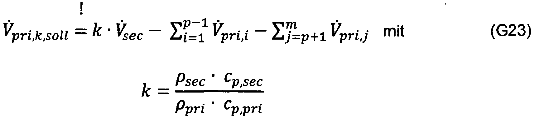
Somit unterscheidet sich die Berechnungsvorschrift für die Sollgröße V̇pri,k,soll bei der Ausführungsvariante mit mehr als einem Erzeugerkreis 14 von derjenigen nach Gleichung G5 lediglich darin, dass die Volumenströme des oder der anderen Erzeugerkreise(s) 14, d.h. der Grundlastpumpen ebenfalls ermittelt und von dem ermittelten, gegebenenfalls gewichteten Volumenstrom V̇sec der Sekundärseite 4 subtrahiert werden. Die Volumenströme der Erzeugerpumpen 14a, 14b können analog den vorherigen Beschreibungen messtechnisch oder rechenrisch ermittelt werden, entweder innerhalb der entsprechenden Pumpe oder außerhalb derselben, entweder mittels der Pumpe selbst oder mittels einer Volumenstrommesseinrichtung.Thus, the calculation rule for the setpoint V̇ pri, k, soll differs in the variant with more than one
Die ermittelten Volumenströme der Grundlasterzeugerkreise 14a werden dann an die Spitzenlastpumpe 17b oder an eine andere Auswertungseinheit übermittelt, um den primärseitigen Sollvolumenstrom V̇pri,k,soll für die zu regelnde Spitzenlastpumpe 17b zu bestimmen. Die Übermittlung kann per Funk oder wie in
Die Berechnung des sekundären Volumenstroms V̇sec in Gleichung G23 kann wie zuvor bei den übrigen Ausführungsvarianten insbesondere nach einer der Gleichungen G6, G7 oder G11a erfolgen, insbesondere auch für medienverschiedene Kreisläufe auf der Primär- 2 und Sekundärseite 4 gemäß Gleichung G19.The calculation of the secondary volume flow V̇ sec in equation G23 can, as before with the other design variants, in particular take place according to one of the equations G6, G7 or G11a, in particular also for media-different circuits on the primary 2 and
Gemäß einer anderen, nicht dargestellten Ausführungsvariante kann die variierende, bedarfsweise anfallende Spitzenlast mit zwei Erzeugerkreisen 14b gedeckt werden, wohingegen mit dem oder den übrigen Erzeugerkreis(en) 14a die Grundlast erbracht wird. Die Grundlast-Erzeuger 18 in diesem Kreis 14a laufen mit maximaler thermischer Leistung. Entsprechendes gilt für deren Grundlastpumpe 17a. Nur die Pumpen 17b der Spitzenlast-Erzeugerkreise 14b passen sich an die Schwankungen im verbraucherseitigen Volumenstrom an, um eine energieeffiziente Heizungspumpenregelung zu erreichen. Daher wird das erfindungsgemäße Verfahren bei dieser Ausführungsvariante (nur) auf diese Spitzenlastpumpen 17b angewendet, während die Grundlastpumpe 17a nicht oder anders geregelt sind. Es sind dann zwei erste primärseitige Umwälzpumpen vorhanden, die erfindungsgemäß geregelt werden.According to another embodiment variant, not shown, the varying, if necessary, peak load can be covered with two
Gemäß einer Ausführungsvariante des erfindungsgemäßen Verfahrens werden nun diejenigen Erzeugerpumpen 17b, die den eine Spitzenlast bedienenden Erzeugerkreisen 14b zugeordnet sind, derart geregelt, dass der gesamte Volumenstrom V̇pri auf der Primärseite 2 dem gesamten Volumenstrom V̇sec auf der Sekundärseite 4 entspricht.According to one variant of the method according to the invention, those generator pumps 17b that are assigned to the
Der Volumenstrom, der durch die Summe der eine Spitzenlast bedienenden Erzeugerkreise 14b gebildet ist, wird analog zu Gleichung G23 ermittelt und dieser Volumenstrom gleichmäßig oder in einem vorgegebenen Verhältnis auf die Spitzenlastpumpen 17b verteilt. Das Volumenstromverhältnis entspricht dabei dem Verhältnis der thermischen Leistungen der eine Spitzenlast bedienenden Erzeugerkreise.The volume flow, which is formed by the sum of the
Gemäß einer Weiterbildung einer der o.g. Ausführungsvarianten kann in dem Erzeugerkreis 14 oder kann in einem, mehreren oder allen Erzeugerkreisen 14a, 14b ein Mischer 21 in der primären Rücklaufleitung 16 oder primären lokalen Rücklaufleitung 19 angeordnet sein. Solche mischerbehafteten Erzeugerkreise 14a', 14b' sind in
Bei diesem Rücklaufmischer 21 wird Medium aus der lokalen Vorlaufleitung 10 der Rücklaufleitung 9 über die Mischleitung 22 beigemischt, um die Rücklauftemperatur anzuheben. Eine derartige Anordnung ist vor allem Heizungsanlagen sinnvoll, die auf der Primärseite einen Konstanttemperaturkessel 18 oder ein Blockheizkraftwerk besitzen. Auf derartige Erzeugerkreise 14a', 14b' können die zuvor beschrieben Zusammenhänge und Berechnungen analog angewendet werden.In this
Der erzeugerspezifische Primärvolumenstrom V̇pri,i eines mischerbehafteten Erzeugerkreises 14a', 14b' kann in diesem Fall aus dem entsprechenden Erzeugerkreisvolumenstrom V̇producer,i analog zu Gleichung G7 und darin eingesetzter Gleichung G10 errechnet werden, wie sich aus den Gleichungen G24a und G24b ergibt: ![]()

- V̇pri,i
- der aus dem i-ten
Erzeugerkreis 14a', 14b' hineinfließende Erzeugerkreisvolumenstrom (Volumenstrom nach dem Rücklaufmischer 21), - V̇producer,i
- der in dem i-ten
Erzeugerkreis 14a', 14b' durch den oder dieErzeuger 18 fließende Erzeugervolumenstrom (Volumenstrom vor dem Rücklaufmischer 21), - Ri
- ein erzeugerspezifischer Korrekturwert,
- TVL,producer,i
- die Temperatur im primären lokalen Vorlauf 20 vor dem
Abzweig zum Rücklaufmischer 21 im i-tenErzeugerkreis 14a', 14b', - TRL,producer,i
- die Temperatur im primären lokalen Rücklauf 19
hinter dem Rücklaufmischer 21 im i-ten Erzeugerkreis14a', 14b', und - TRL,pri
- die Temperatur im zentralen primären Rücklauf 16 ist.
- V̇ pri, i
- the generator circuit volume flow flowing in from the i-
th generator circuit 14a ', 14b' (volume flow after the return mixer 21), - V̇ producer, i
- the generator volume flow flowing in the i-
th generator circuit 14a ', 14b' through the generator or generators 18 (volume flow upstream of the return mixer 21), - R i
- a producer-specific correction value,
- T VL, producer, i
- the temperature in the primary
local flow 20 before the branch to thereturn mixer 21 in the i-th generator circuit 14a ', 14b', - T RL, producer, i
- the temperature in the primary
local return 19 downstream of thereturn mixer 21 in the i-th generator circuit 14a ', 14b', and - T RL, pri
- the temperature in the central
primary return 16 is.
Auf eine Darstellung der physikalischen Zusammenhänge wird an dieser verzichtet, da sie analog zu den Verbraucherkreisen mit Vorlaufmischer 11 sind. Daher kann auf die vorherigen Ausführungen zurückgegriffen werden.The physical relationships are not shown here, since they are analogous to the consumer circuits with a
Um den jeweiligen erzeugerspezifischen Korrekturwert nach Gleichung G24b berechnen zu können, sind die jeweiligen Temperaturen TVL,producer,i und T RL,producer,i der lokalen sekundären Vorlaufleitung 20 und der lokalen sekundären Rücklaufleitung 19 erforderlich. Diese werden erfindungsgemäß entsprechend ermittelt und an die Auswertungsstelle zur Berechnung des Sollvolumenstroms übermittelt, d.h. beispielsweise an die zu regelnde primäre Kreiselpumpe 17 bzw. Spitzenlastpumpe 17b oder eine externe Auswerteeinheit. Wie bei den anderen Ausführungsvarianten kann die Ermittlung durch Messen, berechnen aus anderen gemessenen Größen oder Schätzen aus Modellgrößen erfolgen. Und wie bei den anderen Ausführungsvarianten kann die Übermittlung per Funk oder kabelgebunden, insbesondere über Messleitungen 25 und das Datennetzwerk 19 erfolgen, das den Ermittlungsort mit der Auswertungsstelle kommunikationstechnisch verbindet.In order to be able to calculate the respective producer-specific correction value according to equation G24b, the respective temperatures T VL, producer, i and T RL, producer, i of the local
Wie beispielhaft anhand
Wie in
Für die im Erzeugerkreis 14 angeordnete Erzeugerpumpe 17b kann diese Volumenstromregelung ebenfalls angewendet werden. So kann auch diese Erzeugerpumpe in ihrem Volumenstrom in Abhängigkeit der Summe der verbraucherspezifischen Volumenströme eingeregelt werden. Dies kann auf zweierlei Weise erfolgen, nämlich direkt oder indirekt.This volume flow control can also be used for the
Gemäß dem direkten Weg kann die Erzeugerpumpe 17b den hierfür notwendigen Volumenstromsollwert mitgeteilt bekommen, beispielsweise entweder von der Zubringerpumpe 17c, die diesen Wert berechnet, oder von der zentralen Auswerteeinheit. Die Erzeugerpumpe 17b kann den Volumenstromsollwert jedoch auch selbst berechnen. Hierzu werden dann die dafür benötigten Volumenstrom- und Temperaturwerte aus den Verbraucherkreisen 5a, 5b und dem Zubringerkreis 30 entsprechend an die Erzeugerpumpe 17b übermittelt. In beiden Fällen brauchen im Erzeugerkreis 14 dann grundsätzlich keine Temperaturen ermittelt zu werden.According to the direct route, the
Gemäß dem indirekten Weg kann die Erzeugerpumpe so geregelt werden, dass ihr Volumenstrom auf den Ist-Volumenstrom der Zubringerpumpe 17c eingeregelt wird. Dieser Fall ist letztendlich so zu behandeln, als wenn der Zubringerkreis 30 ein einziger bzw. der einzige Verbraucherkreis wäre. Die zweite Übergabestelle 29 tritt dann aus regelungstechnischer Sicht an die Stelle der ersten Übergabestelle 3. In diesem Fall muss die Erzeugerpumpe 17b also nicht auf einen Summenvolumenstrom geregelt werden, sondern lediglich auf den einen Volumenstrom im Zubringerkreis, der bei Medienverschiedenheit gegebenenfalls durch den Gewichtungsfaktor k zu multiplizieren ist. Im Übrigen dieser Fall analog den vorgenannten Ausführungen und Gleichungen zu behandeln.According to the indirect path, the generator pump can be regulated in such a way that its volume flow is regulated to the actual volume flow of the
Dasselbe gilt für einen in den Figuren nicht dargestellten Fall, dass erzeugerseitig mehr als ein Erzeugerkreis 14 vorhanden ist. Wo bei den vorherigen Ausführungsbeispielen anhand von
- 11
- HeizungsanlageHeating system
- 22
- Primärkreis zur ersten ÜbergabestellePrimary circuit to the first transfer point
- 2a2a
- Primärkreis zur zweiten ÜbergabestellePrimary circuit to the second transfer point
- 33
- erste Übergabestellefirst handover point
- 3a3a
- GegenstromplattenwärmetauscherCounter-flow plate heat exchanger
- 3b3b
- hydraulische Weichehydraulic switch
- 3c3c
- verlustarmer Verteilerlow loss distributor
- 44th
- SekundärkreisSecondary circuit
- 55
- VerbraucherkreisConsumer group
- 66th
- Verbraucherconsumer
- 77th
- zentrale sekundäre Vorlaufleitungcentral secondary flow line
- 88th
- zentrale sekundäre Rücklaufsammelleitungcentral secondary return manifold
- 99
- lokale sekundäre Vorlaufleitunglocal secondary flow line
- 1010
- lokale sekundäre Rücklaufleitunglocal secondary return line
- 1111
- Mischer, VorlaufmischerMixer, pre-flow mixer
- 1212
- Umwälzpumpe, VerbraucherkreispumpeCirculation pump, consumer circuit pump
- 1313
- AusdehnungsgefäßExpansion tank
- 1414th
- ErzeugerkreisProducer group
- 14a14a
- Erzeugerkreis für GrundlastProducer group for base load
- 14b14b
- Erzeugerkreis für SpitzenlastGeneration group for peak load
- 1515th
- primäre Vorlaufleitungprimary flow line
- 1616
- primäre Rücklaufleitungprimary return line
- 1717th
- UmwälzpumpeCirculation pump
- 17a17a
- Erzeugerpumpe für GrundlastGenerator pump for base load
- 17b17b
- Erzeugerpumpe für SpitzenlastGenerator pump for peak load
- 17c, 17d17c, 17d
- ZubringerpumpeFeed pump
- 1818th
- Erzeuger/ KesselProducer / boiler
- 1919th
- DatennetzwerkData network
- 2020th
- DatenleitungData line
- 2121st
- Mischer, RücklaufmischerMixer, return mixer
- 2222nd
- MischleitungMixed pipe
- 2323
- Bypassbypass
- 2424
- Vorlauftemperaturfühler im PrimärkreisFlow temperature sensor in the primary circuit
- 2525th
- TemperaturmessleitungTemperature measuring line
- 2626th
- Rücklauftemperaturfühler im PrimärkreisReturn temperature sensor in the primary circuit
- 2828
- zentrale Kommunikationseinrichtungcentral communication facility
- 2929
- zweite Übergabestellesecond transfer point
- 3030th
- Zubringerkreis, Sekundärkreis zur ersten ÜbergabestelleFeeder circuit, secondary circuit to the first transfer point
- 3131
- Vorlauftemperaturfühler im ersten VerbraucherkreisFlow temperature sensor in the first consumer circuit
- 3232
- Rücklauftemperaturfühler im ersten VerbraucherkreisReturn temperature sensor in the first consumer circuit
- 3333
- Vorlauftemperaturfühler im zweiten VerbraucherkreisFlow temperature sensor in the second consumer circuit
- 3434
- Rücklauftemperaturfühler im zweiten VerbraucherkreisReturn temperature sensor in the second consumer circuit
- 3535
- Vorlauf ZubringerkreisFeed feeder circuit
- 3636
- Rücklauf ZubringerkreisReturn feeder circuit
- 3737
- Vorlauftemperaturfühler im ZubringerkreisFlow temperature sensor in the feeder circuit
- 3838
- Rücklauftemperaturfühler im ZubringerkreisReturn temperature sensor in the feeder circuit
Claims (30)
- Method for controlling at least one first circulation pump (17b, 17c) of a heating or cooling system (1) having a primary circuit (2, 2a) and a secondary circuit (4, 30a) coupled therewith at a transfer point (3, 29), wherein the first circulation pump (17, 17b, 17c, 17b') conveys a heating or cooling medium in the primary circuit (2, 2a) and in the secondary circuit (4, 30a) at least one second circulation pump (12, 17d) is located that conveys a heating or cooling medium in at least one partial area of the secondary circuit (4, 30a), characterized in that the volume flow rate (V̇pri, V̇pri,i ) of the first circulation pump (17, 17b, 17c, 17b') is controlled in functional dependence of the flowing volume flow rate (V̇sec ) of the secondary circuit (4, 30) behind the transfer point (3, 29).
- Method according to claim 1, characterized in that the first circulation pump (17, 17b, 17c, 17b') is controlled in such a way that the volume flow rate (V̇pri ) of the primary circuit (2, 2a) in front of the transfer point (3, 29) is in a predefined ratio (a) to the volume flow rate (V̇ sec) of the secondary circuit (4, 30a) behind the transfer point (3, 29), in particular corresponds to the volume flow rate (V̇sec ) of the secondary circuit (4. 30a) behind the transfer point (3, 29).
- Method according to claim 1 or 2, characterized in that the first circulation pump (17, 17, 17c, 17b') is controlled in such a way that the volume flow rate (V̇pri ) of the primary circuit (2, 2a) in front of the transfer point (3, 29) adheres to a predetermined distance (b) to the volume flow rate (V̇sec ) of the secondary circuit (4, 30) behind the transfer point (3, 29) or to a value (a · V̇sec ) determined therefrom.
- Method according to any one of the preceding claims, characterized in that the primary circuit (2, 2a) comprises at least one generator circuit (14, 14a, 14b, 14a', 14b') in which at least one heating or cooling generator heats or cools the heating or cooling medium and a generator pump (17, 17a, 17b, 17a', 17b') in sequence with the heating or cooling generator (18) which conveys heating or cooling medium of the generator circuit (14, 14a, 14b, 14a', 14b'), wherein the first circulation pump (17, 17b, 17b') to be controlled is this generator pump (17, 17b, 17b').
- Method according to any one of the preceding claims, characterized in that the primary circuit (2, 2a) comprises a number (m) of generator circuits (14, 14a, 14b, 14a', 14b') connected in parallel, in which respectively at least one heating or cooling generator (18) respectively heats or cools the heating or cooling medium and a generator pump (17, 17a, 17b, 17a', 17b') in series with the respective heating or cooling generator (18) conveys a generator-specific volume flow rate (V̇pri,i ), wherein the first circulation pump (17, 17b, 17b') to be controlled is one of these parallel generator pumps (17, 17b, 17b').
- Method according to claim 5, characterized in that the first circulation pump (17, 17b, 17b') to be controlled is the generator pump (17, 17b, 17b') that lies in a peak load providing generator circuit (14b).
- Method according to claim 4, 5 or 6, characterized in that the generator circuit or generator circuits (14, 14a, 14b, 14a', 14b') is/ are directly coupled to the secondary circuit (4) by means of the transfer point (3).
- Method according to claims 1 to 3, characterized in that the primary circuit (2) comprises a feeder circuit (30) which is coupled with the secondary circuit (4) at the transfer point (3), wherein a feeder pump (17c) lies in the feeder circuit (30) which conveys a heating or cooling medium in the feeder circuit (30), and wherein the first circulation pump (17c) to be controlled is this feeder pump (17c).
- Method according to any one of claim 1 to 7, characterized in that the secondary circuit (30a) comprises or forms a feeder circuit (30a) which is coupled to the primary circuit (2a) at the transfer point (29), wherein a feeder pump (17c) lies in the feeder circuit (30a), which conveys a heating or cooling medium in the feeder circuit (30a), and wherein the second circulation pump (17d) is this feeder pump (17d).
- Method according to any one of claims 4 to 7, characterized in that the primary circuit (2) comprises a feeder circuit (30), which is coupled to the secondary circuit (4) at the transfer point (3) and is coupled to the generator circuit(s) (14, 14a, 14b, 14a', 14b') by means of a second transfer point (29), wherein a feeder pump (17c) lies in the feeder circuit (30), which conveys a heating or cooling medium in the feeder circuit (30) and forms a further first circulation pump (17), which is controlled in the same way as the one first circulation pump (17b).
- Method according to any one of the preceding claims, characterized in that the secondary circuit (4) comprises one or a number (n) of consumer circuit(s) (5, 5a, 5b) connected in parallel, in which at least one consumer (6) consumes the respective heat or coolness from the heating or cooling medium, and in which an independently controlled consumer pump (12) in series with the respective consumer (6) conveys the heating or cooling medium in the respective consumer circuit (5a, 5b).
- Method according to any one of the preceding claims, characterized in that the volume flow rate (V̇sec ) of the secondary circuit (4, 30a) is measured or calculated behind the transfer point (3, 29) and is selected as the set point (V̇pri,soll, V̇pri,i,soll ) at the first circulation pump (17b, 17c) or in that a set point (V̇pri,soll, V̇pri,i,soll ) for the volume flow rate of the first circulation pump (17b, 17c) is calculated from the measured or calculated volume flow rate (V̇sec ) of the secondary circuit (4) and is set at the first circulation pump (17b, 17c).
- Method according to any one of the preceding claims, characterized in that with different media in the primary circuit (2) and secondary circuit (4) the volume flow rate (V̇sec ) of the secondary circuit (4, 30a) is weighted with a factor (k) which corresponds to the product of the density ratio and heat capacity ratio of the two media and in that this weighted volume flow rate (V̇sec ) is selected as the set point (V̇pri,soll, V̇pri,i,soll ) at the first circulation pump (17b, 17c) or calculated from a set point (V̇pri,soll , V̇pri,i,soll ) for the volume flow rate of the first circulation pump (17b, 17c) and selected at the first circulation pump (17b, 17c).
- Method according to any one of claims 11 to 13, characterized in that in each of the consumer circuits (5a, 5b) the respective consumer circuit volume flow rate (V̇sec,i ) is measured or calculated and these consumer circuit volume flow rates (V̇sec,i ) are added to obtain a total volume flow rate (V̇sec ) of the secondary circuit (4) and in that the total volume flow rate (V̇sec ) is selected as the set point (V̇pri,soll, V̇pri,i,soll ) at the first circulation pump (17b, 17c) or calculated from a set point (V̇pri,soll , V̇pri,i,soll ) and selected at the first circulation pump (17, 17c).
- Method according to any one of claims 11 to 13, characterized in that in one, two, a plurality or all consumer circuits (5a) one feed flow mixer or one feed flow mixer (11) in each is arranged which admixes to a respective local feed flow (10) of the corresponding consumer circuit (5) a part of the heating or cooling medium of its return flow (9) by means of a mixer line (22), and a consumer volume flow rate (V̇consumer,i ) is determined in the respective consumer circuit (5a) in the flow direction behind the feed flow mixer (11) or in front of the branch to the mixer line (22), and this determined consumer volume flow rate (V̇consumer,i ) is multiplied by a consumer circuit-specific compensation value (Ci) to obtain the respective consumer circuit volume flow rate (V̇sec,i ).
- Method according to claim 15, characterized in that the consumer circuit-specific compensation value (Ci) is formed by the ratio of a first to a second temperature difference, wherein the first temperature difference is between the local feed flow (10) behind the feed flow mixer (11) and the local return flow (9) of the respective consumer circuit (5a) and the second temperature difference is between the central secondary-side feed flow (7) or primary-side feed flow (15) and the local return flow (9) of the respective consumer circuit 5a.
- Method according to claim 15, characterized in that the consumer circuit-specific compensation value (Ci) is calculated from
 Ci is the consumer circuit-specific compensation value of an i-th consumer circuit (5a),TVL.consumer,i is the temperature in the local feed flow (10) behind the feed flow mixer (11) of the ith consumer circuit (5a),TRL.consumer,i is the temperature in the local return flow (9) of the ith consumer circuit (5a),TVL.pri is the temperature in the central primary-side feed flow (15) andΔTpri-sec is the temperature drop from the primary side to the secondary side of the transfer point (3).
 - Method according to claim 17, characterized in that the temperature drop (ΔTpri-sec ) is determined in that in a consumer circuit (5b) without a feed flow mixer the difference between the primary feed flow temperature (TVL.pri ) and the secondary local feed flow temperature (TVL.sec,i ) is calculated, or in that in a consumer circuit (5a) that mixes a return flow medium into the feed flow (7) with a completely opened feed flow mixer (11), the difference between the primary feed flow temperature (TVL.pri ) and the secondary local feed flow temperature (TVL.consumer,i ) behind the feed flow mixer (11) is calculated.
- Method according to claim 14, 15, 16 or 18, characterized in that the consumer circuit volume flow rates (V̇sec,i ) and/or consumer volume flow rates (V̇consumer,i ) are determined inside the consumer pumps (12).
- Method according to any one of claims 14 to 19, characterized in that the determined consumer circuit volume flow rates (V̇sec,i ) are transmitted from the consumer pumps (12) to the first circulation pump (17, 17b, 17c) and/or a central evaluation unit (28) to calculate the volume flow rate set point (V̇pri,soll, V̇pri,i,soll ).
- Method according to any one of claims 16 to 20, characterized in that the temperature in the local feed flow (10) is measured behind the feed flow mixer (11) and in the local return flow (9) of the respective consumer circuit (5a) as well as the temperature in the central secondary-side feed flow (7) or the primary-side feed flow (15).
- Method according to any one of claims 16 to 21, characterized in that the first or second temperature difference is calculated and saved and is updated each time if the feed flow mixer (11) of the respective consumer circuit is completely opened again in the through flow direction to the consumer.
- Method according to claim 13, characterized in that the factor (k) is determined from the temperature spread (ΔTpri ) and the volume flow rate (V̇pri ) in the primary circuit (2) of the transfer point (3) as well as the temperature spread (ΔTsec ) and the volume flow rate (V̇pri ) in the secondary circuit (4) according to the equation
 k is the weight factor,V̇pri is the total volume flow rate in the primary circuit (2),V̇sec is the total volume flow rate in the secondary circuit (4),ΔTpri is the temperature spread on the primary side of the transfer point (3), andΔTsec is the temperature spread on the secondary side of the transfer point (3).
 - Method according to any one of claims 5 to 23, characterized in that the generator circuit volume flow rates (V̇pri,i ) of the generator circulation pumps (17a) of all generator circuits (14a, 14a') providing a thermal base load are each determined and the sum of which is provided, and in that this sum is subtracted from the determined secondary volume flow rate (V̇sec ) and this difference is selected as a set point (V̇pri,i,soll ) at the first circulation pump (17b) or it is calculated from said difference a set point (V̇pri,i,soll ) for the volume flow rate of the first circulation pump (17b) and selected at the first circulation pump (17b).
- Method according to any one of claims 11 to 24, characterized in that in one, two, a plurality or all generator circuits (14a') one return flow mixer or one return flow mixer (21) in each is arranged which admixes to a respective local return flow (19) of the corresponding generator circuit (5) a part of the heating or cooling medium of its feed flow (20) by means of a mixer line (22), and a generator volume flow rate (V̇producer,i ) is determined in the respective generator circuit (14a') in the flow direction behind the return flow mixer (11) or in front of the branch to the mixer line (22), and this determined generator volume flow rate (V̇producer,i ) is multiplied by a generator circuit-specific compensation value (Ri) to obtain the respective generator circuit volume flow rate (V̇pri,i ).
- Method according to claim 25, characterized in that the generator circuit-specific compensation value (Ri) is calculated from
 Ri is a generator-specific compensation value,TVL,producer,i is the temperature in the primary local feed flow 20 in the i-th generator circuit 14a', 14b',TRL,producer,i is the temperature in the primary local return flow 19 behind the return flow mixer 21 in the i-th generator circuit 14a', 14b' andTRL,pri is the temperature in the central primary-side return flow 16.
 - Method according to claim 24, 25 or 26, characterized in that the generator circuit volume flow rates (V̇pri,i ) or generator volume flow rates (V̇producer,i ) are determined inside the generator circulation pump (14a, 17b) of the corresponding generator circuit (14a, 14b, 14a', 14b').
- Method according to any one of the preceding claims, characterized in that the transfer point (3) and/or the second transfer point (29) is a heat exchanger (3a), a hydraulic separator (3b) or a distributor (3c), wherein the distributor (3c) directly connects the feed flow line (7) of the primary circuit (2) to the central feed flow line (7) of the secondary circuit (4) and also directly connects the central return line (8) of the secondary circuit (4) to the return line (16) of the primary circuit (2) and the secondary central feed flow line (7) and return line (8) are directly connected to one another by means of a bypass.
- Pump system with at least one first circulation pump (17b, 17c) for conveying a heating or cooling medium in a primary circuit (2) of a heating or cooling system (1) and at least one second circulation pump (12, 17d) for conveying a heating or cooling medium in at least a partial area of a secondary circuit (4, 30a) coupled with the primary circuit (2) via a transfer point (3), characterized in that it is configured for implementing the method according to any one of clams 1 to 28.
- Circulation pump (17b, 17c) for conveying a heating or cooling medium in a primary circuit (2) of a heating or cooling system (1) with a pump electronics system for determining a set point (V̇pri,soll, V̇pri,i,soll ), characterized in that it is controllable in its volume flow rate (V̇pri , V̇pri,i ) and, for that, it is configured to calculate a volume flow set point (V̇pri,soll , V̇pri,i,soll ) itself in functional dependence of the flowing volume flow rate (V̇sec, V̇sec,i ) of at least one other circulation pump (12, 17d) for the intended conveying of a heating or cooling medium in a secondary circuit (4) of the heating or cooling system (1).
Applications Claiming Priority (2)
| Application Number | Priority Date | Filing Date | Title |
|---|---|---|---|
| DE102015014378.6A DE102015014378A1 (en) | 2015-11-09 | 2015-11-09 | Method for controlling a centrifugal pump and associated pump system |
| PCT/EP2016/001776 WO2017080632A1 (en) | 2015-11-09 | 2016-10-26 | Method for controlling a centrifugal pump, and associated pump system |
Publications (2)
| Publication Number | Publication Date |
|---|---|
| EP3374699A1 EP3374699A1 (en) | 2018-09-19 |
| EP3374699B1 true EP3374699B1 (en) | 2020-09-23 |
Family
ID=57542951
Family Applications (1)
| Application Number | Title | Priority Date | Filing Date |
|---|---|---|---|
| EP16809630.3A Active EP3374699B1 (en) | 2015-11-09 | 2016-10-26 | Method for controlling a centrifugal pump, and associated pump system |
Country Status (5)
| Country | Link |
|---|---|
| US (1) | US10883507B2 (en) |
| EP (1) | EP3374699B1 (en) |
| CN (1) | CN108463672B (en) |
| DE (1) | DE102015014378A1 (en) |
| WO (1) | WO2017080632A1 (en) |
Cited By (1)
| Publication number | Priority date | Publication date | Assignee | Title |
|---|---|---|---|---|
| US20230109989A1 (en) * | 2021-10-07 | 2023-04-13 | Accademia Europea Bolzano - Eurac Research | Regulation system for a thermo-hydraulic circuit and control method |
Families Citing this family (8)
| Publication number | Priority date | Publication date | Assignee | Title |
|---|---|---|---|---|
| DE102015014378A1 (en) | 2015-11-09 | 2017-05-11 | Wilo Se | Method for controlling a centrifugal pump and associated pump system |
| DE202017007063U1 (en) | 2017-03-13 | 2019-05-07 | Wilo Se | Configuration wizard for a variable speed centrifugal pump unit |
| DE102017123705A1 (en) * | 2017-10-12 | 2019-04-18 | Viessmann Werke Gmbh & Co Kg | Refrigerated cabinets with integrated hydraulic control and cooling system |
| US11692752B2 (en) * | 2018-10-05 | 2023-07-04 | S. A. Armstrong Limited | Feed forward flow control of heat transfer system |
| SE543008C2 (en) * | 2018-11-22 | 2020-09-22 | Stockholm Exergi Ab | Method and system for balancing mass flow during production disruption or shortage in a district heating network |
| DE102020123209A1 (en) | 2020-09-04 | 2022-03-10 | Viessmann Werke Gmbh & Co Kg | Power system and method for controlling a power system with hydraulic system separation |
| DE102020134503A1 (en) | 2020-12-21 | 2022-06-23 | Techem Energy Services Gmbh | Method and device for controlling a primary circuit of a heating system |
| WO2024105026A1 (en) * | 2022-11-14 | 2024-05-23 | Grundfos Holding A/S | Method and system for controlling a flow of fluid in a mixing loop |
Citations (4)
| Publication number | Priority date | Publication date | Assignee | Title |
|---|---|---|---|---|
| EP2151578A1 (en) | 2008-08-04 | 2010-02-10 | Grundfos Management A/S | Circulation pump system |
| EP2874039A1 (en) | 2013-11-19 | 2015-05-20 | Grundfos Holding A/S | Control method for a heat transfer system and heat transfer system |
| EP2960587A1 (en) | 2014-06-24 | 2015-12-30 | Grundfos Holding A/S | Method for limiting the supply flow rate in a heat transfer system |
| WO2017080632A1 (en) | 2015-11-09 | 2017-05-18 | Wilo Se | Method for controlling a centrifugal pump, and associated pump system |
Family Cites Families (20)
| Publication number | Priority date | Publication date | Assignee | Title |
|---|---|---|---|---|
| US4316434A (en) * | 1980-02-13 | 1982-02-23 | Bailey Burners, Inc. | Method and apparatus for improving heat transfer |
| SE9601181D0 (en) * | 1996-03-27 | 1996-03-27 | Alf Ottosson | Methods and apparatus for temperature control of tap hot water |
| US6065946A (en) * | 1997-07-03 | 2000-05-23 | Servo Magnetics, Inc. | Integrated controller pump |
| ATA119897A (en) | 1997-07-14 | 1998-09-15 | Seebacher Theodor | HEATING SUPPLY SYSTEM FOR AT LEAST ONE CONSUMER CIRCUIT |
| DE19912588A1 (en) | 1999-03-20 | 2000-09-21 | Ksb Ag | Fluid transport system |
| US7484888B2 (en) * | 2000-12-21 | 2009-02-03 | Tark, Inc. | Method and system for cooling heat-generating component in a closed-loop system |
| ATE406547T1 (en) * | 2001-05-03 | 2008-09-15 | Matts Lindgren | METHOD AND ARRANGEMENT FOR CONTROLLING THE TEMPERATURE OF THE OUTGOING POWER FROM A HEAT EXCHANGER AND MEASUREMENT OF HEAT GENERATED |
| JP3917835B2 (en) * | 2001-09-28 | 2007-05-23 | 横河電機株式会社 | Pressurized water pump system |
| DE10163987A1 (en) | 2001-12-24 | 2003-07-10 | Grundfos As | Method for controlling a variable speed heating circulation pump |
| DE10315402A1 (en) * | 2003-04-04 | 2004-11-04 | Voith Turbo Gmbh & Co. Kg | Drive system and method for optimizing the energy supply for a cooling system of a drive system |
| DE102005041486B4 (en) | 2004-09-17 | 2020-03-19 | Delta Systemtechnik Gmbh | Plant for heating or preheating water |
| DE102006004179B4 (en) * | 2006-01-27 | 2007-10-18 | Danfoss A/S | Valve arrangement for connecting a heat exchanger of a hot water extraction device to a district heating network |
| DE102007040629A1 (en) | 2007-08-27 | 2009-03-05 | Oewa Wasser Und Abwasser Gmbh | Safety heat exchanger for the combination of a heat pump with a device of a public drinking water supply system |
| WO2010087759A1 (en) * | 2009-01-30 | 2010-08-05 | D-Con | District heating substation control |
| DE102009017423B4 (en) * | 2009-04-15 | 2020-10-08 | Stiebel Eltron Gmbh & Co. Kg | Method for charge control of a hot water stratified storage tank with a heat pump |
| CN101799189A (en) * | 2010-04-06 | 2010-08-11 | 天津艾耐尔热能设备有限公司 | Water-mixing regulating method and device of secondary network system of heat exchange unit |
| DK2893228T3 (en) * | 2012-08-01 | 2020-06-02 | Parker Hannifin Corp | Cartridge assembly and valve with such cartridge assembly |
| JP5845161B2 (en) * | 2012-10-16 | 2016-01-20 | 本田技研工業株式会社 | Cogeneration equipment |
| CN203421772U (en) * | 2013-07-09 | 2014-02-05 | 浙江大学昆山创新中心 | Intelligent heat exchange station |
| US20170219219A1 (en) * | 2016-02-01 | 2017-08-03 | Keith A. Miller | Demand based hvac (heating, ventilation, air conditioning) control |
-
2015
- 2015-11-09 DE DE102015014378.6A patent/DE102015014378A1/en active Pending
-
2016
- 2016-10-26 US US15/774,406 patent/US10883507B2/en active Active
- 2016-10-26 EP EP16809630.3A patent/EP3374699B1/en active Active
- 2016-10-26 CN CN201680064989.XA patent/CN108463672B/en active Active
- 2016-10-26 WO PCT/EP2016/001776 patent/WO2017080632A1/en active Application Filing
Patent Citations (5)
| Publication number | Priority date | Publication date | Assignee | Title |
|---|---|---|---|---|
| EP2151578A1 (en) | 2008-08-04 | 2010-02-10 | Grundfos Management A/S | Circulation pump system |
| WO2010015318A2 (en) * | 2008-08-04 | 2010-02-11 | Grundfos Management A/S | Circulating pump unit |
| EP2874039A1 (en) | 2013-11-19 | 2015-05-20 | Grundfos Holding A/S | Control method for a heat transfer system and heat transfer system |
| EP2960587A1 (en) | 2014-06-24 | 2015-12-30 | Grundfos Holding A/S | Method for limiting the supply flow rate in a heat transfer system |
| WO2017080632A1 (en) | 2015-11-09 | 2017-05-18 | Wilo Se | Method for controlling a centrifugal pump, and associated pump system |
Cited By (1)
| Publication number | Priority date | Publication date | Assignee | Title |
|---|---|---|---|---|
| US20230109989A1 (en) * | 2021-10-07 | 2023-04-13 | Accademia Europea Bolzano - Eurac Research | Regulation system for a thermo-hydraulic circuit and control method |
Also Published As
| Publication number | Publication date |
|---|---|
| US10883507B2 (en) | 2021-01-05 |
| DE102015014378A1 (en) | 2017-05-11 |
| CN108463672A (en) | 2018-08-28 |
| CN108463672B (en) | 2021-03-02 |
| US20190331119A1 (en) | 2019-10-31 |
| WO2017080632A1 (en) | 2017-05-18 |
| EP3374699A1 (en) | 2018-09-19 |
Similar Documents
| Publication | Publication Date | Title |
|---|---|---|
| EP3374699B1 (en) | Method for controlling a centrifugal pump, and associated pump system | |
| EP2960587B1 (en) | Method for limiting the supply flow rate in a heat transfer system | |
| EP0035085B2 (en) | Installation for heat transport by means of a fluid | |
| EP2788689B1 (en) | Method for regulating the room temperature in a room or in a group comprising multiple rooms, and apparatus for carrying out the method | |
| DE10312825B4 (en) | Method for setting a plurality of parallel-connected heat exchangers | |
| EP2870414B1 (en) | Method for operating a heat exchanger and hvac installation for implementing the method | |
| EP2187136A2 (en) | Method for operating a system for transporting thermal energy through a liquid medium | |
| EP3101352B1 (en) | Method for operating a heating installation and controller with differential pressure sensor | |
| DE102010023777A1 (en) | Heating system for use in building, has heat pump providing heat to high and low temperature heating circuits, where reversing valve connects output of heat pump with input of heat storage volume or with input of another storage volume | |
| EP0892223B1 (en) | Control and command system for a heating system | |
| DE19859364C2 (en) | Heat supply system with peak load limitation | |
| EP2009536B1 (en) | Method and device for setting the heating reserve | |
| DE60119551T2 (en) | District heating arrangement, local unit of a district heating arrangement, control unit for the local unit and method for operating a district heating arrangement | |
| EP3026352A1 (en) | Method for hydraulically regulating several heating circuits on the distributor beam | |
| DE4312150C2 (en) | Method for adjusting the delivery rate of a circulation pump | |
| EP0445310A1 (en) | Method and device for in-temperature regulation of a multi-boiler heating system | |
| EP0987498A2 (en) | Pump control | |
| EP2327971B1 (en) | Method for analysing the heat volume distribution in a heating system and device for executing the method | |
| EP3367005B1 (en) | Heating system | |
| DE102020120839A1 (en) | Temperature control device with a reduced number of temperature sensors | |
| EP1154205B1 (en) | Heat transport system with heat production installation having flow rate control | |
| EP2910861A1 (en) | System for cooling or heating and system for compensation of a water or steam system for cooling or heating | |
| EP4015918A1 (en) | Method and device for controlling a primary circuit of a heating installation | |
| EP3369934A1 (en) | Circulation pump | |
| DE10214735A1 (en) | Heat exchanger in parallel connection for domestic water heating |
Legal Events
| Date | Code | Title | Description |
|---|---|---|---|
| STAA | Information on the status of an ep patent application or granted ep patent |
Free format text: STATUS: UNKNOWN |
|
| STAA | Information on the status of an ep patent application or granted ep patent |
Free format text: STATUS: THE INTERNATIONAL PUBLICATION HAS BEEN MADE |
|
| PUAI | Public reference made under article 153(3) epc to a published international application that has entered the european phase |
Free format text: ORIGINAL CODE: 0009012 |
|
| STAA | Information on the status of an ep patent application or granted ep patent |
Free format text: STATUS: REQUEST FOR EXAMINATION WAS MADE |
|
| 17P | Request for examination filed |
Effective date: 20180605 |
|
| AK | Designated contracting states |
Kind code of ref document: A1 Designated state(s): AL AT BE BG CH CY CZ DE DK EE ES FI FR GB GR HR HU IE IS IT LI LT LU LV MC MK MT NL NO PL PT RO RS SE SI SK SM TR |
|
| AX | Request for extension of the european patent |
Extension state: BA ME |
|
| RIN1 | Information on inventor provided before grant (corrected) |
Inventor name: SCHMIED, STEPHAN |
|
| DAV | Request for validation of the european patent (deleted) | ||
| DAX | Request for extension of the european patent (deleted) | ||
| STAA | Information on the status of an ep patent application or granted ep patent |
Free format text: STATUS: EXAMINATION IS IN PROGRESS |
|
| 17Q | First examination report despatched |
Effective date: 20191022 |
|
| GRAP | Despatch of communication of intention to grant a patent |
Free format text: ORIGINAL CODE: EPIDOSNIGR1 |
|
| STAA | Information on the status of an ep patent application or granted ep patent |
Free format text: STATUS: GRANT OF PATENT IS INTENDED |
|
| INTG | Intention to grant announced |
Effective date: 20200511 |
|
| GRAS | Grant fee paid |
Free format text: ORIGINAL CODE: EPIDOSNIGR3 |
|
| GRAA | (expected) grant |
Free format text: ORIGINAL CODE: 0009210 |
|
| STAA | Information on the status of an ep patent application or granted ep patent |
Free format text: STATUS: THE PATENT HAS BEEN GRANTED |
|
| AK | Designated contracting states |
Kind code of ref document: B1 Designated state(s): AL AT BE BG CH CY CZ DE DK EE ES FI FR GB GR HR HU IE IS IT LI LT LU LV MC MK MT NL NO PL PT RO RS SE SI SK SM TR |
|
| REG | Reference to a national code |
Ref country code: GB Ref legal event code: FG4D Free format text: NOT ENGLISH |
|
| REG | Reference to a national code |
Ref country code: CH Ref legal event code: EP |
|
| REG | Reference to a national code |
Ref country code: DE Ref legal event code: R096 Ref document number: 502016011282 Country of ref document: DE |
|
| REG | Reference to a national code |
Ref country code: IE Ref legal event code: FG4D Free format text: LANGUAGE OF EP DOCUMENT: GERMAN |
|
| REG | Reference to a national code |
Ref country code: AT Ref legal event code: REF Ref document number: 1316771 Country of ref document: AT Kind code of ref document: T Effective date: 20201015 |
|
| PG25 | Lapsed in a contracting state [announced via postgrant information from national office to epo] |
Ref country code: GR Free format text: LAPSE BECAUSE OF FAILURE TO SUBMIT A TRANSLATION OF THE DESCRIPTION OR TO PAY THE FEE WITHIN THE PRESCRIBED TIME-LIMIT Effective date: 20201224 Ref country code: NO Free format text: LAPSE BECAUSE OF FAILURE TO SUBMIT A TRANSLATION OF THE DESCRIPTION OR TO PAY THE FEE WITHIN THE PRESCRIBED TIME-LIMIT Effective date: 20201223 Ref country code: BG Free format text: LAPSE BECAUSE OF FAILURE TO SUBMIT A TRANSLATION OF THE DESCRIPTION OR TO PAY THE FEE WITHIN THE PRESCRIBED TIME-LIMIT Effective date: 20201223 Ref country code: HR Free format text: LAPSE BECAUSE OF FAILURE TO SUBMIT A TRANSLATION OF THE DESCRIPTION OR TO PAY THE FEE WITHIN THE PRESCRIBED TIME-LIMIT Effective date: 20200923 Ref country code: FI Free format text: LAPSE BECAUSE OF FAILURE TO SUBMIT A TRANSLATION OF THE DESCRIPTION OR TO PAY THE FEE WITHIN THE PRESCRIBED TIME-LIMIT Effective date: 20200923 Ref country code: SE Free format text: LAPSE BECAUSE OF FAILURE TO SUBMIT A TRANSLATION OF THE DESCRIPTION OR TO PAY THE FEE WITHIN THE PRESCRIBED TIME-LIMIT Effective date: 20200923 |
|
| PG25 | Lapsed in a contracting state [announced via postgrant information from national office to epo] |
Ref country code: LV Free format text: LAPSE BECAUSE OF FAILURE TO SUBMIT A TRANSLATION OF THE DESCRIPTION OR TO PAY THE FEE WITHIN THE PRESCRIBED TIME-LIMIT Effective date: 20200923 Ref country code: RS Free format text: LAPSE BECAUSE OF FAILURE TO SUBMIT A TRANSLATION OF THE DESCRIPTION OR TO PAY THE FEE WITHIN THE PRESCRIBED TIME-LIMIT Effective date: 20200923 |
|
| REG | Reference to a national code |
Ref country code: NL Ref legal event code: MP Effective date: 20200923 |
|
| REG | Reference to a national code |
Ref country code: LT Ref legal event code: MG4D |
|
| PG25 | Lapsed in a contracting state [announced via postgrant information from national office to epo] |
Ref country code: SM Free format text: LAPSE BECAUSE OF FAILURE TO SUBMIT A TRANSLATION OF THE DESCRIPTION OR TO PAY THE FEE WITHIN THE PRESCRIBED TIME-LIMIT Effective date: 20200923 Ref country code: EE Free format text: LAPSE BECAUSE OF FAILURE TO SUBMIT A TRANSLATION OF THE DESCRIPTION OR TO PAY THE FEE WITHIN THE PRESCRIBED TIME-LIMIT Effective date: 20200923 Ref country code: CZ Free format text: LAPSE BECAUSE OF FAILURE TO SUBMIT A TRANSLATION OF THE DESCRIPTION OR TO PAY THE FEE WITHIN THE PRESCRIBED TIME-LIMIT Effective date: 20200923 Ref country code: PT Free format text: LAPSE BECAUSE OF FAILURE TO SUBMIT A TRANSLATION OF THE DESCRIPTION OR TO PAY THE FEE WITHIN THE PRESCRIBED TIME-LIMIT Effective date: 20210125 Ref country code: RO Free format text: LAPSE BECAUSE OF FAILURE TO SUBMIT A TRANSLATION OF THE DESCRIPTION OR TO PAY THE FEE WITHIN THE PRESCRIBED TIME-LIMIT Effective date: 20200923 Ref country code: LT Free format text: LAPSE BECAUSE OF FAILURE TO SUBMIT A TRANSLATION OF THE DESCRIPTION OR TO PAY THE FEE WITHIN THE PRESCRIBED TIME-LIMIT Effective date: 20200923 |
|
| PG25 | Lapsed in a contracting state [announced via postgrant information from national office to epo] |
Ref country code: ES Free format text: LAPSE BECAUSE OF FAILURE TO SUBMIT A TRANSLATION OF THE DESCRIPTION OR TO PAY THE FEE WITHIN THE PRESCRIBED TIME-LIMIT Effective date: 20200923 Ref country code: AL Free format text: LAPSE BECAUSE OF FAILURE TO SUBMIT A TRANSLATION OF THE DESCRIPTION OR TO PAY THE FEE WITHIN THE PRESCRIBED TIME-LIMIT Effective date: 20200923 Ref country code: IS Free format text: LAPSE BECAUSE OF FAILURE TO SUBMIT A TRANSLATION OF THE DESCRIPTION OR TO PAY THE FEE WITHIN THE PRESCRIBED TIME-LIMIT Effective date: 20210123 Ref country code: PL Free format text: LAPSE BECAUSE OF FAILURE TO SUBMIT A TRANSLATION OF THE DESCRIPTION OR TO PAY THE FEE WITHIN THE PRESCRIBED TIME-LIMIT Effective date: 20200923 |
|
| REG | Reference to a national code |
Ref country code: CH Ref legal event code: PL |
|
| REG | Reference to a national code |
Ref country code: DE Ref legal event code: R026 Ref document number: 502016011282 Country of ref document: DE |
|
| PLBI | Opposition filed |
Free format text: ORIGINAL CODE: 0009260 |
|
| PG25 | Lapsed in a contracting state [announced via postgrant information from national office to epo] |
Ref country code: MC Free format text: LAPSE BECAUSE OF FAILURE TO SUBMIT A TRANSLATION OF THE DESCRIPTION OR TO PAY THE FEE WITHIN THE PRESCRIBED TIME-LIMIT Effective date: 20200923 Ref country code: SK Free format text: LAPSE BECAUSE OF FAILURE TO SUBMIT A TRANSLATION OF THE DESCRIPTION OR TO PAY THE FEE WITHIN THE PRESCRIBED TIME-LIMIT Effective date: 20200923 Ref country code: LU Free format text: LAPSE BECAUSE OF NON-PAYMENT OF DUE FEES Effective date: 20201026 |
|
| PLAX | Notice of opposition and request to file observation + time limit sent |
Free format text: ORIGINAL CODE: EPIDOSNOBS2 |
|
| REG | Reference to a national code |
Ref country code: BE Ref legal event code: MM Effective date: 20201031 |
|
| 26 | Opposition filed |
Opponent name: GRUNDFOS HOLDING A/S Effective date: 20210622 |
|
| PG25 | Lapsed in a contracting state [announced via postgrant information from national office to epo] |
Ref country code: DK Free format text: LAPSE BECAUSE OF FAILURE TO SUBMIT A TRANSLATION OF THE DESCRIPTION OR TO PAY THE FEE WITHIN THE PRESCRIBED TIME-LIMIT Effective date: 20200923 Ref country code: BE Free format text: LAPSE BECAUSE OF NON-PAYMENT OF DUE FEES Effective date: 20201031 Ref country code: CH Free format text: LAPSE BECAUSE OF NON-PAYMENT OF DUE FEES Effective date: 20201031 Ref country code: LI Free format text: LAPSE BECAUSE OF NON-PAYMENT OF DUE FEES Effective date: 20201031 Ref country code: SI Free format text: LAPSE BECAUSE OF FAILURE TO SUBMIT A TRANSLATION OF THE DESCRIPTION OR TO PAY THE FEE WITHIN THE PRESCRIBED TIME-LIMIT Effective date: 20200923 |
|
| PG25 | Lapsed in a contracting state [announced via postgrant information from national office to epo] |
Ref country code: IE Free format text: LAPSE BECAUSE OF NON-PAYMENT OF DUE FEES Effective date: 20201026 |
|
| PLBB | Reply of patent proprietor to notice(s) of opposition received |
Free format text: ORIGINAL CODE: EPIDOSNOBS3 |
|
| PG25 | Lapsed in a contracting state [announced via postgrant information from national office to epo] |
Ref country code: TR Free format text: LAPSE BECAUSE OF FAILURE TO SUBMIT A TRANSLATION OF THE DESCRIPTION OR TO PAY THE FEE WITHIN THE PRESCRIBED TIME-LIMIT Effective date: 20200923 Ref country code: MT Free format text: LAPSE BECAUSE OF FAILURE TO SUBMIT A TRANSLATION OF THE DESCRIPTION OR TO PAY THE FEE WITHIN THE PRESCRIBED TIME-LIMIT Effective date: 20200923 Ref country code: CY Free format text: LAPSE BECAUSE OF FAILURE TO SUBMIT A TRANSLATION OF THE DESCRIPTION OR TO PAY THE FEE WITHIN THE PRESCRIBED TIME-LIMIT Effective date: 20200923 |
|
| PG25 | Lapsed in a contracting state [announced via postgrant information from national office to epo] |
Ref country code: MK Free format text: LAPSE BECAUSE OF FAILURE TO SUBMIT A TRANSLATION OF THE DESCRIPTION OR TO PAY THE FEE WITHIN THE PRESCRIBED TIME-LIMIT Effective date: 20200923 |
|
| REG | Reference to a national code |
Ref country code: AT Ref legal event code: MM01 Ref document number: 1316771 Country of ref document: AT Kind code of ref document: T Effective date: 20211026 |
|
| PG25 | Lapsed in a contracting state [announced via postgrant information from national office to epo] |
Ref country code: AT Free format text: LAPSE BECAUSE OF NON-PAYMENT OF DUE FEES Effective date: 20211026 |
|
| PG25 | Lapsed in a contracting state [announced via postgrant information from national office to epo] |
Ref country code: NL Free format text: LAPSE BECAUSE OF NON-PAYMENT OF DUE FEES Effective date: 20200923 |
|
| P01 | Opt-out of the competence of the unified patent court (upc) registered |
Effective date: 20230615 |
|
| APBM | Appeal reference recorded |
Free format text: ORIGINAL CODE: EPIDOSNREFNO |
|
| APBP | Date of receipt of notice of appeal recorded |
Free format text: ORIGINAL CODE: EPIDOSNNOA2O |
|
| APAH | Appeal reference modified |
Free format text: ORIGINAL CODE: EPIDOSCREFNO |
|
| APBM | Appeal reference recorded |
Free format text: ORIGINAL CODE: EPIDOSNREFNO |
|
| APBP | Date of receipt of notice of appeal recorded |
Free format text: ORIGINAL CODE: EPIDOSNNOA2O |
|
| APBQ | Date of receipt of statement of grounds of appeal recorded |
Free format text: ORIGINAL CODE: EPIDOSNNOA3O |
|
| APBQ | Date of receipt of statement of grounds of appeal recorded |
Free format text: ORIGINAL CODE: EPIDOSNNOA3O |
|
| PGFP | Annual fee paid to national office [announced via postgrant information from national office to epo] |
Ref country code: IT Payment date: 20230920 Year of fee payment: 8 Ref country code: GB Payment date: 20230920 Year of fee payment: 8 |
|
| PGFP | Annual fee paid to national office [announced via postgrant information from national office to epo] |
Ref country code: FR Payment date: 20230920 Year of fee payment: 8 |
|
| PGFP | Annual fee paid to national office [announced via postgrant information from national office to epo] |
Ref country code: DE Payment date: 20230920 Year of fee payment: 8 |