EP3101352B1 - Method for operating a heating installation and controller with differential pressure sensor - Google Patents
Method for operating a heating installation and controller with differential pressure sensor Download PDFInfo
- Publication number
- EP3101352B1 EP3101352B1 EP16172083.4A EP16172083A EP3101352B1 EP 3101352 B1 EP3101352 B1 EP 3101352B1 EP 16172083 A EP16172083 A EP 16172083A EP 3101352 B1 EP3101352 B1 EP 3101352B1
- Authority
- EP
- European Patent Office
- Prior art keywords
- heating
- pump
- differential pressure
- controller
- volumetric flow
- Prior art date
- Legal status (The legal status is an assumption and is not a legal conclusion. Google has not performed a legal analysis and makes no representation as to the accuracy of the status listed.)
- Active
Links
- 238000010438 heat treatment Methods 0.000 title claims description 68
- 238000000034 method Methods 0.000 title claims description 16
- 238000009434 installation Methods 0.000 title description 3
- 230000008859 change Effects 0.000 claims description 4
- 238000007619 statistical method Methods 0.000 claims description 4
- 238000001514 detection method Methods 0.000 claims 1
- 230000003247 decreasing effect Effects 0.000 description 2
- 239000000446 fuel Substances 0.000 description 2
- 239000012528 membrane Substances 0.000 description 2
- XLYOFNOQVPJJNP-UHFFFAOYSA-N water Substances O XLYOFNOQVPJJNP-UHFFFAOYSA-N 0.000 description 2
- 230000006978 adaptation Effects 0.000 description 1
- 230000000712 assembly Effects 0.000 description 1
- 238000000429 assembly Methods 0.000 description 1
- 230000008901 benefit Effects 0.000 description 1
- 230000033228 biological regulation Effects 0.000 description 1
- 238000006243 chemical reaction Methods 0.000 description 1
- 230000007812 deficiency Effects 0.000 description 1
- 238000010586 diagram Methods 0.000 description 1
- 238000005516 engineering process Methods 0.000 description 1
- 239000012530 fluid Substances 0.000 description 1
- 230000009931 harmful effect Effects 0.000 description 1
- 230000003993 interaction Effects 0.000 description 1
- 230000008569 process Effects 0.000 description 1
- 238000005086 pumping Methods 0.000 description 1
- 230000009467 reduction Effects 0.000 description 1
- 230000032258 transport Effects 0.000 description 1
Images


Classifications
-
- F—MECHANICAL ENGINEERING; LIGHTING; HEATING; WEAPONS; BLASTING
- F24—HEATING; RANGES; VENTILATING
- F24D—DOMESTIC- OR SPACE-HEATING SYSTEMS, e.g. CENTRAL HEATING SYSTEMS; DOMESTIC HOT-WATER SUPPLY SYSTEMS; ELEMENTS OR COMPONENTS THEREFOR
- F24D19/00—Details
- F24D19/10—Arrangement or mounting of control or safety devices
- F24D19/1006—Arrangement or mounting of control or safety devices for water heating systems
- F24D19/1009—Arrangement or mounting of control or safety devices for water heating systems for central heating
- F24D19/1012—Arrangement or mounting of control or safety devices for water heating systems for central heating by regulating the speed of a pump
-
- Y—GENERAL TAGGING OF NEW TECHNOLOGICAL DEVELOPMENTS; GENERAL TAGGING OF CROSS-SECTIONAL TECHNOLOGIES SPANNING OVER SEVERAL SECTIONS OF THE IPC; TECHNICAL SUBJECTS COVERED BY FORMER USPC CROSS-REFERENCE ART COLLECTIONS [XRACs] AND DIGESTS
- Y02—TECHNOLOGIES OR APPLICATIONS FOR MITIGATION OR ADAPTATION AGAINST CLIMATE CHANGE
- Y02B—CLIMATE CHANGE MITIGATION TECHNOLOGIES RELATED TO BUILDINGS, e.g. HOUSING, HOUSE APPLIANCES OR RELATED END-USER APPLICATIONS
- Y02B30/00—Energy efficient heating, ventilation or air conditioning [HVAC]
- Y02B30/70—Efficient control or regulation technologies, e.g. for control of refrigerant flow, motor or heating
Definitions
- the invention relates to a method for operating a heating system, in which at least via a central supply and discharge line heating medium is guided or discharged to heating circuits. Furthermore, the invention also relates to a controller with differential pressure sensor.
- heating circuits In the heating technology of larger buildings, it is state of the art to connect several heating circuits to a central supply and discharge line, for example to a distribution bar. This corresponds to a parallel connection of the heating circuits. Most of the heating circuits have their own pump and their own mixer, with which a weather-compensated return admixture for each heating circuit is realized.
- Hydraulic balancing of the heating circuits on the manifold ensures that each heating circuit is supplied with the heat output it needs (provided that the flow temperature to the manifold is sufficient).
- throttling devices such as differential pressure regulators, which are to be used in each heating circuit. At them usually via a spring force acting on a membrane, a target differential pressure is set. The two sides of the membrane are with pressure transmitting pipes with fore and aft Return connected. Depending on the setpoint / actual difference, the diaphragm changes the valve seat, ie the flow cross-section, so that a constant differential pressure is established between flow and return. This then adapts dynamically to the heat requirement / volume flow.
- Differential pressure regulators have the disadvantage that the water supplied during pumping flow energy is unused swirled.
- differential pressure regulators create additional pressure loss to exercise their valve authority.
- a very high control characteristic for example, proportional pressure characteristic Hv
- Hv proportional pressure characteristic
- volume flow Q A linear relationship is usual, but other functional relationships between volume flow Q and nominal head H have been proposed (for example, a root function in FIG EP 0 726 396 B1 or even a flow constant regulation DE 2946 049 A1 ).
- a change in the system characteristic curve is always detected on the basis of a change in the volume flow (also referred to below as the flow), which is either measured directly with a flow sensor or computationally calculated from the electrical operating variables of the motor with the aid of an implemented pump characteristic diagram ( EP 0 150 068 A3 or DE 2946 049 A1 ).
- the self-regulating pumps have over the differential pressure regulators the advantage that only as much electrical energy is expended, as is necessary for the operation of the heating circuit.
- the self-regulating pumps used on the manifold have the major disadvantage that they can not distinguish whether a volume flow reduction is caused by the thermostatic valves in their own heating circuit or in another heating circuit. However, opposite reactions are required. If other heating circuits increase their volume flow, the pump reduces their speed because the pressure loss in the boiler circuit has increased. The heat requirement in our own heating circuit has actually remained constant and a speed increase would have been necessary to keep the volume flow constant.
- EP 2 775 370 A2 a device is described, which has the aim to enable the hydraulic balancing or a better distribution of the heating power. It consists of several parallel fluid circuits, in particular heating circuits on a manifold with or without weathered Rulaufismeischung, each with a variable speed pump, each with a flow sensor, each a Vorund return temperature sensor, with a common flow temperature sensor of the distributor and at least one controller.
- this concept only works if there is an exchange of information between the heating circuits, because the actual controlled variable is not measured. Higher acquisition costs are the result.
- the model-based approach makes the software more difficult to transfer to other dimensions or products.
- a power and fuel-saving operation of the heating circulation pumps should be made possible.
- the process should be retrofittable without great effort in existing systems and be applicable to other plant dimensions.
- mutually different setpoint values are preferably reserved for heating types that differ from each other.
- Different heating types can be, for example, surface heating, radiator heating or storage afterheating.
- standard setpoints are stored in the controller, for example 100 mbar for radiator heating, which are loaded when selecting the heating type. It makes sense that the standard setpoints can be adapted by the craftsman to local conditions.
- the volume flow in the heating circuit is additionally detected and the setpoint value is adjusted as a function of the volume flow. The larger the volume flow, the greater the pressure loss in the pipeline to the radiators.
- each heating circuit can be assigned a limit value for the volume flow, upon reaching the speed of the pump is reduced so that the limit is not exceeded. By offsetting it is avoided that a heating circuit sucks too much volumetric flow due to a wrong setpoint, and a deficiency occurs in others.
- the volume flow can be calculated by the pump and transmitted to the control or be detected by means of a connected to the control flow sensor.
- FIG. 1 shows a known heating system with a boiler 1 and a heating circuit manifold 6 with a non-mixed heating circuit 2 and two weather-compensated heating circuits 3 with mixer 7.
- the heating circuits are equipped with self-regulating pumps 8 and a hydraulic switch 5 below the distributor.
- the purpose of the hydraulic diverter 5 is that the distributor 6 becomes low differential pressure, and the heating circuits 2, 3 influence each other less.
- the heating circuit pumps are easy to adjust and save energy during operation.
- the disadvantage is that a further pump, the boiler pump 4, is required. If it fails, the entire heat supply of the building fails.
- the lack of adjustment of the volume flows above and below the hydraulic separator ensures that the return is usually mixed with hot water from the flow. This increases the fuel consumption of the heat generator, such as heat pump or condensing boiler, whose efficiency is significantly influenced by the return temperature.
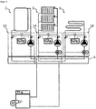
- FIG. 2 shows the system according to the invention with a boiler 1 and a heating circuit manifold 6 with a non-mixed heating circuit 2 and two weather-compensated heating circuits 3 with mixer.
- the pumps do not regulate themselves, but are influenced by a controller 11 in their speed. Connected to the controller are the differential pressure sensors 10, and the variable-speed pumps 8. The controller also has the volume flow signal of the pump connected.
- two temperature sensors are connected to the controller.
- the controllers 11 are interconnected via a bus connection 12 with each other.
- the inventive method allows by appropriate control of the pump only spend as much energy or pressure as is needed for the supply. This allows both a power-saving operation of the pumps and achieves a low return temperature by omitting the hydraulic switch. Furthermore, in case of failure of a pump continues to heat supply of building parts.
- FIG. 3 shows a heating system with a boiler 1 and a Schuffyverteiler 6 with a Bank Vietnamesepaktmodul without mixer 13 for the storage load and two Schu Vietnamesepaktmodule with motorized mixer 14 for a radiator circuit and a réellegeber Vietnamese.
- the industrially prefabricated assemblies bring the installer a great deal of time during installation, but also when ordering.
- various stored setpoint values for the differential pressure in the controller are selected. This makes the installation easier for the installer.
- For a floor heating circuit For example, 150 mbar is stored, while for a radiator heating circuit 100 mbar are stored.
Description
Die Erfindung betrifft ein Verfahren zum Betreiben einer Heizungsanlage, bei dem zumindest über eine zentrale Zuführungs- und Abführungsleitung Heizmedium zu Heizkreisläufen geführt beziehungsweise abgeführt wird. Weiterhin betrifft die Erfindung auch einen Regler mit Differenzdrucksensor.The invention relates to a method for operating a heating system, in which at least via a central supply and discharge line heating medium is guided or discharged to heating circuits. Furthermore, the invention also relates to a controller with differential pressure sensor.
In der Heizungstechnik größerer Gebäude ist es Stand der Technik mehrere Heizkreisläufe an eine zentrale Zuführungs- und Abführungsleitung, zum Beispiel an einen Verteilerbalken, anzuschließen. Dies entspricht einer Parallelschaltung der Heizkreisläufe. Die meisten der Heizkreisläufe verfügen über eine eigene Pumpe und einen eigenen Mischer, mit dem eine witterungsgeführte Rücklaufbeimischung für jeden Heizkreis realisiert wird.In the heating technology of larger buildings, it is state of the art to connect several heating circuits to a central supply and discharge line, for example to a distribution bar. This corresponds to a parallel connection of the heating circuits. Most of the heating circuits have their own pump and their own mixer, with which a weather-compensated return admixture for each heating circuit is realized.
Ein hydraulischer Abgleich der Heizkreisläufe auf dem Verteilerbalken gewährleistet, dass jeder Heizkreislauf mit der Wärmeleistung versorgt wird, die er benötigt (sofern die Vorlauftemperatur in den Verteiler ausreichend ist). Hier kennt der Stand der Technik zwei Möglichkeiten.
Erstens sind es Drosselorgane wie Differenzdruckregler, die in jedem Heizkreislauf einzusetzen sind. An ihnen wird üblicherweise über eine Federkraft, die auf eine Membran wirkt, ein Soll-Differenzdruck eingestellt. Die zwei Seiten der Membran sind mit druckübertragenden Rohren mit Vor- und Rücklauf verbunden. Die Membran verändert abhängig von Soll-/Ist-Differenz den Ventilsitz, also den Strömungsquerschnitt, so dass sich zwischen Vorlauf und Rücklauf ein konstanter Differenzdruck einstellt. Dieser passt sich dann dynamisch an den Wärmebedarf/Volumenstrom an. Differenzdruckregler haben den Nachteil, dass dem Wasser beim Pumpen zugeführte Strömungsenergie ungenutzt verwirbelt wird. Zudem erzeugen Differenzdruckregler einen zusätzlichen Druckverlust, um ihre Ventilautorität auszuüben. An den Pumpen muss eine sehr hohe Regelkennlinie (zum Beispiel Proportionaldruckkennlinie H-v) eingestellt werden, um den zusätzlichen Druckverlust auszugleichen. Das erhöht den Stromverbrauch signifikant. Außerdem sind Differenzdruckregler in der Anschaffung teuer.Hydraulic balancing of the heating circuits on the manifold ensures that each heating circuit is supplied with the heat output it needs (provided that the flow temperature to the manifold is sufficient). Here, the state of the art knows two ways.
First, there are throttling devices such as differential pressure regulators, which are to be used in each heating circuit. At them usually via a spring force acting on a membrane, a target differential pressure is set. The two sides of the membrane are with pressure transmitting pipes with fore and aft Return connected. Depending on the setpoint / actual difference, the diaphragm changes the valve seat, ie the flow cross-section, so that a constant differential pressure is established between flow and return. This then adapts dynamically to the heat requirement / volume flow. Differential pressure regulators have the disadvantage that the water supplied during pumping flow energy is unused swirled. In addition, differential pressure regulators create additional pressure loss to exercise their valve authority. At the pumps, a very high control characteristic (for example, proportional pressure characteristic Hv) must be set to compensate for the additional pressure drop. This significantly increases power consumption. In addition, differential pressure regulator in the purchase are expensive.
Zweitens sind es selbstregelnde Pumpen, die außer einer Konstantdrehzahlkennlinie (n-c) meist eine Proportionaldruckkennlinie (H-v) oder eine Konstantdruckkennlinie (H-c) implementiert haben (H weil der erzeugte Druck in der Praxis Förderhöhe genannt wird). Bei der Konstantdruckkennlinie wird zu jeder Stellung der Heizkörperventile, also für jede Anlagenkennlinie, die Pumpendrehzahl n so eingestellt, dass sich die gleiche Förderhöhe H bezogen auf die Anschlussstutzen der Pumpe ergibt. Bei der Proportionaldruckkennlinie steigt die Soll-Förderhöhe H(Q) proportional zum Volumenstrom Q an bzw. fällt nach links ab. Dem liegt die Erkenntnis zugrunde, dass ein abnehmender Volumenstrom mit einer Abnahme des Wärmebedarfs einhergeht und die Druckverluste in der Verteilleitung zurückgehen.Secondly, there are self-regulating pumps that have implemented a proportional pressure characteristic (Hv) or a constant pressure characteristic (Hc) in addition to a constant speed characteristic (Hc) (H because the pressure generated in practice is called delivery head). In the constant pressure characteristic curve, the pump speed n is set for each position of the radiator valves, that is to say for each system characteristic curve, in such a way that the same delivery height H results based on the connection stubs of the pump. In the case of the proportional pressure characteristic curve, the nominal delivery head H (Q) increases in proportion to the volume flow Q or drops to the left. This is based on the finding that a decreasing volume flow is accompanied by a decrease in the heat requirement and that the pressure losses in the distribution line decrease.
Gebräuchlich ist ein linearer Zusammenhang, es sind jedoch auch andere funktionale Zusammenhänge zwischen Volumenstrom Q und Soll-Förderhöhe H vorgeschlagen worden (zum Beispiel eine Wurzelfunktion in
Die selbstregelnden Pumpen am Verteilerbalken eingesetzt haben den großen Nachteil, dass sie nicht unterscheiden können, ob eine Volumenstromreduktion durch die Thermostatventile im eigenen Heizkreislauf oder in einem anderen Heizkreislauf verursacht wird. Es sind jedoch gegenteilige Reaktionen erforderlich. Erhöhen andere Heizkreisläufe ihren Volumenstrom, reduziert die Pumpe ihre Drehzahl, weil der Druckverlust im Kesselkreislauf zugenommen hat. Der Wärmebedarf im eigenen Heizkreislauf ist eigentlich konstant geblieben und eine Drehzahlerhöhung wäre erforderlich gewesen, um den Volumenstrom konstant zu halten.The self-regulating pumps used on the manifold have the major disadvantage that they can not distinguish whether a volume flow reduction is caused by the thermostatic valves in their own heating circuit or in another heating circuit. However, opposite reactions are required. If other heating circuits increase their volume flow, the pump reduces their speed because the pressure loss in the boiler circuit has increased. The heat requirement in our own heating circuit has actually remained constant and a speed increase would have been necessary to keep the volume flow constant.
In
Ein weiterer Lösungsansatz ist es, den Verteiler differenzdruckarm zu gestalten, indem ein hydraulischer Kurzschluss zwischen Vorlauf und Rücklauf, zum Beispiel mit einer hydraulischen Weiche, realisiert wird. Dadurch wird die gegenseitige Beeinflussung reduziert und die Pumpen können bei niedriger Drehzahl betrieben werden. Nachteilig ist jedoch, dass eine weitere Pumpe im Kesselkreislauf notwendig wird, die die Wärme zur hydraulischen Weiche transportiert. Fällt diese Pumpe aus, liegt die gesamte Wärmeversorgung darnieder. Der große Nachteil besteht aber darin, dass die Volumenströme des Kesselkreislaufs und der Heizkreisläufe nicht abgeglichen sind und somit häufig die hohe Vorlauftemperatur dem Rücklauf beigemischt wird. Die höhere Rücklauftemperatur reduziert die Effizienz des Wärmeerzeugers und kostet Brennstoff. In
Diese Aufgabe ist verfahrensseitig erfindungsgemäß durch die kennzeichnenden Merkmale des Anspruchs 1 gelöst. Bei dem erfindungsgemäßen Verfahren wird der Differenzdruck zwischen Vorlauf- und Rücklaufleitung des Heizkreislaufs gemessen. Dazu wird kein Abschnitt der Vorlaufleitung bzw. der Rücklaufleitung reduziert, so dass keine zusätzlichen Druckverluste auftreten.This object is achieved procedurally according to the invention by the characterizing features of claim 1. In the method according to the invention, the differential pressure between the supply and return line of the heating circuit is measured. For this purpose, no section of the flow line or the return line is reduced, so that no additional pressure losses occur.
Änderungen des Wärmebedarfs im eigenen Heizkreislauf sowie Wechselwirkungen mit anderen Heizkreisläufen werden anhand einer Änderung des Differenzdrucks detektiert und können mit Hilfe der in den Heizkreislauf eingesetzten Pumpe ausgeglichen werden. Das Ausgleichen erfolgt schnell und simultan in jedem Heizkreislauf, indem über ein Regelsignal (zum Beispiel PWM) die Drehzahl der Pumpe erhöht beziehungsweise erniedrigt wird, wenn der Differenzdruck unter den Sollwert fällt beziehungsweise über den Sollwert steigt. Der Modulationsbereich der Pumpe, also der verwendete Drehzahlbereich, erhöht sich gegenüber dem Stand der Technik deutlich, so dass die eingesetzte Pumpe über weite Teile des Jahres in einem Arbeitsbereich gefahren werden kann, der weit unterhalb ihrer typischen Kennlinie liegt. Die Pumpe kann mit geringen Drehzahlen betrieben werden, so dass ein schonender und zugleich energiesparender Betrieb der Pumpe eintritt. Als Regelungsansatz können Algorithmen wie P-Regler, PI-Regler und PID-Regler eingesetzt werden.Changes in the heat demand in the own heating circuit as well as interactions with other heating circuits are detected by a change of the differential pressure and can be compensated by means of the pump inserted in the heating circuit. The equalization takes place quickly and simultaneously in each heating circuit by the speed of the pump is increased or decreased via a control signal (for example, PWM) when the differential pressure falls below the setpoint or rises above the setpoint. The modulation range of the pump, that is, the speed range used, increases significantly over the prior art, so that the pump used can be driven over much of the year in a work area, which is far below their typical characteristic. The pump can be operated at low speeds, so that a gentle and at the same time energy-saving operation of the pump occurs. As a control approach algorithms such as P-controller, PI controller and PID controller can be used.
Nach einer ersten Weiterbildung der Erfindung ist vorgesehen, dass voneinander verschiedene Sollwerte vorzugsweise für voneinander verschiedene Heizungstypen vorgehalten werden. Verschiedene Heiztypen können beispielsweise Flächenheizungen, Radiatorheizungen oder Speichernachheizungen sein. Für die jeweiligen Heizungstypen sind im Regler Standard-Sollwerte hinterlegt, zum Beispiel 100 mbar für Radiatorheizungen, die beim Auswählen des Heizungstyps geladen werden. Es ist sinnvoll, dass die Standard-Sollwerte vom Handwerker an die örtlichen Gegebenheiten angepasst werden können. Erfindungsgemäß wird neben dem Messen des Differenzdrucks zusätzlich der volumenstrom im Heizkreislauf erfasst und der Sollwert abhängig vom Volumenstrom angepasst. Je größer der Volumenstrom ist, desto größer ist der Druckverlust in der Rohrleitung zu den Heizkörpern. Das heißt, um den Differenzdruck über dem Heizkörper konstant zu halten ist es sinnvoll, den Sollwert mit steigendem Volumenstrom zu vergrößern. Hierfür bietet sich aufgrund der Natur der Rohrleitungsdruckverlust vor allem ein linearer oder quadratischer Zusammenhang zwischen Volumenstrom und Differenzdruck an. Die Funktion insbesondere die Steigung kann an die örtlichen Gegebenheiten angepasst werden.According to a first development of the invention, it is provided that mutually different setpoint values are preferably reserved for heating types that differ from each other. Different heating types can be, for example, surface heating, radiator heating or storage afterheating. For the respective heating types, standard setpoints are stored in the controller, for example 100 mbar for radiator heating, which are loaded when selecting the heating type. It makes sense that the standard setpoints can be adapted by the craftsman to local conditions. According to the invention, in addition to measuring the differential pressure, the volume flow in the heating circuit is additionally detected and the setpoint value is adjusted as a function of the volume flow. The larger the volume flow, the greater the pressure loss in the pipeline to the radiators. In other words, in order to keep the differential pressure above the radiator constant, it makes sense to increase the setpoint with increasing volumetric flow. Due to the nature of the pipeline pressure loss, a linear or quadratic relationship between volume flow and differential pressure is particularly suitable for this purpose. The function in particular the slope can be adapted to the local conditions.
In einer vorteilhaften Weiterbildung der Erfindung ist vorgesehen, dass jedem Heizkreislauf ein Grenzwert für den Volumenstrom zugewiesen werden kann, bei dessen Erreichen die Drehzahl der Pumpe derart reduziert wird, dass der Grenzwert nicht überschritten wird. Durch das Abregeln wird vermieden, dass ein Heizkreislauf aufgrund eines falschen Sollwertes zu viel Volumenstrom saugt und bei anderen eine Unterversorgung auftritt. Der Volumenstrom kann dabei von der Pumpe errechnet werden und an die Regelung übermittelt werden oder mit Hilfe eines an die Regelung angeschlossenen Durchflusssensors erfasst werden.In an advantageous development of the invention, it is provided that each heating circuit can be assigned a limit value for the volume flow, upon reaching the speed of the pump is reduced so that the limit is not exceeded. By offsetting it is avoided that a heating circuit sucks too much volumetric flow due to a wrong setpoint, and a deficiency occurs in others. The volume flow can be calculated by the pump and transmitted to the control or be detected by means of a connected to the control flow sensor.
Schließlich ist es möglich, eine fortlaufende statistische Analyse der Parameter, Differenzdruck, gegebenenfalls Volumenstrom, Vorlauftemperatur und/oder der Pumpendrehzahl durchzuführen und die Höhe des Soll-Differenzdrucks daran anzupassen. Die automatische Adaption nimmt den Handwerker die Feinjustierung des Soll-Differenzdrucks ab und optimiert den Betriebspunkt der Pumpe.Finally, it is possible to carry out a continuous statistical analysis of the parameters, differential pressure, optionally volume flow, flow temperature and / or the pump speed and to adjust the height of the desired differential pressure thereon. The automatic adaptation reduces the craftsman's fine adjustment of the target differential pressure and optimizes the operating point of the pump.
Weiterhin kann noch der Regler über Busleitungen mit anderen Pumpendrehzahlreglern verbunden werden und eine statistische Analyse der Betriebsparameter über alle Heizkreisläufe gemeinsam durchgeführt werden. Denkbar ist auch ein einziger Regler, der mit den Pumpen und Sensoren aller Heizkreise verbunden ist. Ausführungsbeispiele der Erfindung sind in den
- Figur 1:
- eine Heizungsanlage nach dem Stand der Technik mit einer zentralen Zuführungs- und Abführungsleitung, einer hydraulischen Weiche und drei Heizkreisen;
- Figur 2:
- eine erste Ausführung einer Heizungsanlage, die nach dem erfindungsgemäßen Verfahren betrieben wird; und
- Figur 3:
- eine zweite Ausführung einer Heizungsanlage, gleichfalls betrieben nach dem erfindungsgemäßen Verfahren.
- FIG. 1:
- a heating system according to the prior art with a central supply and discharge line, a hydraulic switch and three heating circuits;
- FIG. 2:
- a first embodiment of a heating system, which is operated by the method according to the invention; and
- FIG. 3:
- a second embodiment of a heating system, also operated by the method according to the invention.
Claims (7)
- A method for operating a heating system, in which heating medium is guided and discharged to heating circuits at least via a central supply and discharge line, and in which the differential pressure between feed and return line of the heating circuit (2, 3) is measured in each heating circuit (2, 3), the measured pressure value is compared with a stored set-point value and the differential pressure in the heating circuit (2, 3) is adjusted to the set-point value using a speed change of a pump (8) used in the heating circuit (2, 3),
characterized
in that the volumetric flow in the heating circuit (2, 3) is additionally detected and the differential-pressure set-point value is adapted as a function of the volumetric flow in accordance with a functional relationship, particularly in accordance with a linear relationship with positive gradient. - The method according to Claim 1, characterized in that mutually differing set-point values are preferably kept for heating types which differ from one another.
- The method according to Claim 1 or 2, characterized in that the speed of the pump (8) is reduced if a settable limit value of the volumetric flow is reached.
- The method according to one of the preceding claims, characterized in that the volumetric flow is calculated with the aid of the pump (8) and transmitted to a control (11).
- The method according to one of the preceding claims, characterized in that a continuous statistical analysis of the parameters differential pressure, volumetric flow, feed temperature and/or speed of the pump (8) is carried out and the level of the set-point differential pressure is adapted thereto.
- The method according to one of Claims 1 to 4, characterized in that the controller (11) is connected to other pump speed controllers (11) via bus lines (12) and a statistical analysis of the operating parameters across all heating circuits (2, 3) is determined jointly and the level of the set-point differential pressures is adapted thereto.
- A controller for at least one heating-circuit circulation pump in each case having a differential pressure sensor, feed and return temperature sensors, variable-speed pump and volumetric flow detection, characterized in that an algorithm for implementing the method according to one of Claims 1 to 6 is implemented in the controller.
Applications Claiming Priority (1)
| Application Number | Priority Date | Filing Date | Title |
|---|---|---|---|
| DE102015006779.6A DE102015006779A1 (en) | 2015-06-01 | 2015-06-01 | Method for operating a heating system and controller with differential pressure sensor |
Publications (2)
| Publication Number | Publication Date |
|---|---|
| EP3101352A1 EP3101352A1 (en) | 2016-12-07 |
| EP3101352B1 true EP3101352B1 (en) | 2017-06-28 |
Family
ID=56344968
Family Applications (1)
| Application Number | Title | Priority Date | Filing Date |
|---|---|---|---|
| EP16172083.4A Active EP3101352B1 (en) | 2015-06-01 | 2016-05-31 | Method for operating a heating installation and controller with differential pressure sensor |
Country Status (3)
| Country | Link |
|---|---|
| EP (1) | EP3101352B1 (en) |
| DE (1) | DE102015006779A1 (en) |
| DK (1) | DK3101352T3 (en) |
Families Citing this family (4)
| Publication number | Priority date | Publication date | Assignee | Title |
|---|---|---|---|---|
| DE102017115231A1 (en) * | 2017-07-07 | 2019-01-10 | Rehau Ag + Co | Method for assigning a heating circuit temperature sensor of a heating and / or cooling system to the relevant heating circuit or for checking the assignment of a heating circuit temperature sensor of a heating and / or cooling system to the relevant heating circuit |
| EP3546840A3 (en) * | 2018-03-30 | 2020-05-27 | Bosch Termoteknik Isitma ve Klima Sanayi Ticaret Anonim Sirketi | Water heater |
| PT110846A (en) * | 2018-07-13 | 2020-01-13 | Bosch Termotecnologia Sa | PROCESS FOR THE OPERATION OF A HEATING SYSTEM AND HEATING SYSTEM. |
| DE102021101965A1 (en) * | 2021-01-28 | 2022-07-28 | Viessmann Climate Solutions Se | Heating system and method for operating a heating system |
Family Cites Families (8)
| Publication number | Priority date | Publication date | Assignee | Title |
|---|---|---|---|---|
| DE2946049A1 (en) | 1979-11-15 | 1981-05-27 | Hoechst Ag, 6000 Frankfurt | Circulation pump flow-rate regulation system - measures pump loading and rotation to obtain actual flow-rate |
| DE3402120A1 (en) | 1984-01-23 | 1985-07-25 | Rheinhütte vorm. Ludwig Beck GmbH & Co, 6200 Wiesbaden | METHOD AND DEVICE FOR CONTROLLING DIFFERENT OPERATING PARAMETERS FOR PUMPS AND COMPRESSORS |
| DE19504232A1 (en) | 1995-02-09 | 1996-08-22 | Grundfos As | Method for limiting the performance of electrically driven heating circulation pumps |
| DE19842174A1 (en) * | 1998-09-15 | 2000-03-16 | Wilo Gmbh | Pump control |
| DE10139510B4 (en) * | 2001-08-10 | 2006-10-19 | Robert Bosch Gmbh | Method for controlling the speed of a circulating pump |
| DE102006054893A1 (en) * | 2006-11-20 | 2008-05-21 | Wilo Ag | Compact heating installation |
| DE102008004126B4 (en) * | 2008-01-11 | 2018-01-04 | Rolf Schulze | Method of controlling costs in heat distribution systems |
| DE102013003933A1 (en) | 2013-03-08 | 2014-09-11 | Paw Gmbh & Co. Kg | Device for heating rooms, comprising at least one central heat source and heating circuits associated with the rooms |
-
2015
- 2015-06-01 DE DE102015006779.6A patent/DE102015006779A1/en not_active Withdrawn
-
2016
- 2016-05-31 EP EP16172083.4A patent/EP3101352B1/en active Active
- 2016-05-31 DK DK16172083.4T patent/DK3101352T3/en active
Non-Patent Citations (1)
| Title |
|---|
| None * |
Also Published As
| Publication number | Publication date |
|---|---|
| DK3101352T3 (en) | 2017-10-09 |
| EP3101352A1 (en) | 2016-12-07 |
| DE102015006779A1 (en) | 2016-12-01 |
Similar Documents
| Publication | Publication Date | Title |
|---|---|---|
| EP3101352B1 (en) | Method for operating a heating installation and controller with differential pressure sensor | |
| EP3593055B1 (en) | Method for operating a heating installation | |
| EP2187136A2 (en) | Method for operating a system for transporting thermal energy through a liquid medium | |
| DE102004017593B3 (en) | Cooling and / or heating device | |
| DE102007010768B4 (en) | Method for optimizing valve position and pump speed in a valve system with PID control without the use of external signals | |
| WO2015055482A1 (en) | Method for adapting a heating curve | |
| EP0892223B1 (en) | Control and command system for a heating system | |
| EP2636959B1 (en) | Heater control | |
| EP3473939B1 (en) | Method for operating a heating assembly and heating assembly | |
| EP3026352A1 (en) | Method for hydraulically regulating several heating circuits on the distributor beam | |
| DE102012008436B4 (en) | Method for controlling a hydrodynamic coupling | |
| DE102014202738A1 (en) | Method for automated hydraulic balancing of a refining plant | |
| EP3919823A1 (en) | Method for controlling heat generation and distribution in a heating system | |
| DE102012109483A1 (en) | System for controlling power supply system, used in ship, has control device to determine manipulated variable as energy inefficient manipulated variable, if control objective is not achieved with manipulated variable | |
| AT406081B (en) | HEATING SYSTEM | |
| EP1191287A2 (en) | Pipe system for thermal energy exchange | |
| DE10144595B4 (en) | Central heating system | |
| DE102005040792B3 (en) | Control device for a combination heating device comprises a control unit formed as a self-learning pilot control unit | |
| EP1310746B1 (en) | Device and method for control of fluid heater | |
| EP3168540A1 (en) | Method for carrying out an automated hydraulic balance, valve and heating system for same | |
| EP3217101A1 (en) | Method for hydraulic decoupling of multiple fluid circuits connected in parallel | |
| DE102012101850A1 (en) | Method for controlling heating system of building, involves providing flow rate of heat carrier in generator circuit as input variable by which control variable of power of generator is affected, where generator controls heating power | |
| EP4015918A1 (en) | Method and device for controlling a primary circuit of a heating installation | |
| DE102021117668A1 (en) | Method for operating a circulating pump of a heating system, storage medium, regulation and control unit, heating system and use of a starting pressure and an end pressure | |
| DE102014000327A1 (en) | Control of parallel operated cryogenic refrigeration systems |
Legal Events
| Date | Code | Title | Description |
|---|---|---|---|
| PUAI | Public reference made under article 153(3) epc to a published international application that has entered the european phase |
Free format text: ORIGINAL CODE: 0009012 |
|
| AK | Designated contracting states |
Kind code of ref document: A1 Designated state(s): AL AT BE BG CH CY CZ DE DK EE ES FI FR GB GR HR HU IE IS IT LI LT LU LV MC MK MT NL NO PL PT RO RS SE SI SK SM TR |
|
| AX | Request for extension of the european patent |
Extension state: BA ME |
|
| 17P | Request for examination filed |
Effective date: 20161215 |
|
| RBV | Designated contracting states (corrected) |
Designated state(s): AL AT BE BG CH CY CZ DE DK EE ES FI FR GB GR HR HU IE IS IT LI LT LU LV MC MK MT NL NO PL PT RO RS SE SI SK SM TR |
|
| GRAP | Despatch of communication of intention to grant a patent |
Free format text: ORIGINAL CODE: EPIDOSNIGR1 |
|
| INTG | Intention to grant announced |
Effective date: 20170329 |
|
| GRAS | Grant fee paid |
Free format text: ORIGINAL CODE: EPIDOSNIGR3 |
|
| GRAA | (expected) grant |
Free format text: ORIGINAL CODE: 0009210 |
|
| AK | Designated contracting states |
Kind code of ref document: B1 Designated state(s): AL AT BE BG CH CY CZ DE DK EE ES FI FR GB GR HR HU IE IS IT LI LT LU LV MC MK MT NL NO PL PT RO RS SE SI SK SM TR |
|
| REG | Reference to a national code |
Ref country code: GB Ref legal event code: FG4D Free format text: NOT ENGLISH |
|
| REG | Reference to a national code |
Ref country code: CH Ref legal event code: EP |
|
| REG | Reference to a national code |
Ref country code: AT Ref legal event code: REF Ref document number: 905224 Country of ref document: AT Kind code of ref document: T Effective date: 20170715 |
|
| REG | Reference to a national code |
Ref country code: IE Ref legal event code: FG4D Free format text: LANGUAGE OF EP DOCUMENT: GERMAN |
|
| REG | Reference to a national code |
Ref country code: DE Ref legal event code: R096 Ref document number: 502016000046 Country of ref document: DE |
|
| REG | Reference to a national code |
Ref country code: CH Ref legal event code: NV Representative=s name: PATENTANWAELTE SCHAAD, BALASS, MENZL AND PARTN, CH |
|
| REG | Reference to a national code |
Ref country code: DK Ref legal event code: T3 Effective date: 20171006 |
|
| PG25 | Lapsed in a contracting state [announced via postgrant information from national office to epo] |
Ref country code: GR Free format text: LAPSE BECAUSE OF FAILURE TO SUBMIT A TRANSLATION OF THE DESCRIPTION OR TO PAY THE FEE WITHIN THE PRESCRIBED TIME-LIMIT Effective date: 20170929 Ref country code: FI Free format text: LAPSE BECAUSE OF FAILURE TO SUBMIT A TRANSLATION OF THE DESCRIPTION OR TO PAY THE FEE WITHIN THE PRESCRIBED TIME-LIMIT Effective date: 20170628 Ref country code: NO Free format text: LAPSE BECAUSE OF FAILURE TO SUBMIT A TRANSLATION OF THE DESCRIPTION OR TO PAY THE FEE WITHIN THE PRESCRIBED TIME-LIMIT Effective date: 20170928 Ref country code: HR Free format text: LAPSE BECAUSE OF FAILURE TO SUBMIT A TRANSLATION OF THE DESCRIPTION OR TO PAY THE FEE WITHIN THE PRESCRIBED TIME-LIMIT Effective date: 20170628 Ref country code: LT Free format text: LAPSE BECAUSE OF FAILURE TO SUBMIT A TRANSLATION OF THE DESCRIPTION OR TO PAY THE FEE WITHIN THE PRESCRIBED TIME-LIMIT Effective date: 20170628 |
|
| REG | Reference to a national code |
Ref country code: NL Ref legal event code: MP Effective date: 20170628 |
|
| REG | Reference to a national code |
Ref country code: LT Ref legal event code: MG4D |
|
| PG25 | Lapsed in a contracting state [announced via postgrant information from national office to epo] |
Ref country code: SE Free format text: LAPSE BECAUSE OF FAILURE TO SUBMIT A TRANSLATION OF THE DESCRIPTION OR TO PAY THE FEE WITHIN THE PRESCRIBED TIME-LIMIT Effective date: 20170628 Ref country code: NL Free format text: LAPSE BECAUSE OF FAILURE TO SUBMIT A TRANSLATION OF THE DESCRIPTION OR TO PAY THE FEE WITHIN THE PRESCRIBED TIME-LIMIT Effective date: 20170628 Ref country code: RS Free format text: LAPSE BECAUSE OF FAILURE TO SUBMIT A TRANSLATION OF THE DESCRIPTION OR TO PAY THE FEE WITHIN THE PRESCRIBED TIME-LIMIT Effective date: 20170628 Ref country code: LV Free format text: LAPSE BECAUSE OF FAILURE TO SUBMIT A TRANSLATION OF THE DESCRIPTION OR TO PAY THE FEE WITHIN THE PRESCRIBED TIME-LIMIT Effective date: 20170628 Ref country code: BG Free format text: LAPSE BECAUSE OF FAILURE TO SUBMIT A TRANSLATION OF THE DESCRIPTION OR TO PAY THE FEE WITHIN THE PRESCRIBED TIME-LIMIT Effective date: 20170928 |
|
| PG25 | Lapsed in a contracting state [announced via postgrant information from national office to epo] |
Ref country code: SK Free format text: LAPSE BECAUSE OF FAILURE TO SUBMIT A TRANSLATION OF THE DESCRIPTION OR TO PAY THE FEE WITHIN THE PRESCRIBED TIME-LIMIT Effective date: 20170628 Ref country code: EE Free format text: LAPSE BECAUSE OF FAILURE TO SUBMIT A TRANSLATION OF THE DESCRIPTION OR TO PAY THE FEE WITHIN THE PRESCRIBED TIME-LIMIT Effective date: 20170628 Ref country code: CZ Free format text: LAPSE BECAUSE OF FAILURE TO SUBMIT A TRANSLATION OF THE DESCRIPTION OR TO PAY THE FEE WITHIN THE PRESCRIBED TIME-LIMIT Effective date: 20170628 |
|
| PG25 | Lapsed in a contracting state [announced via postgrant information from national office to epo] |
Ref country code: IS Free format text: LAPSE BECAUSE OF FAILURE TO SUBMIT A TRANSLATION OF THE DESCRIPTION OR TO PAY THE FEE WITHIN THE PRESCRIBED TIME-LIMIT Effective date: 20171028 Ref country code: PL Free format text: LAPSE BECAUSE OF FAILURE TO SUBMIT A TRANSLATION OF THE DESCRIPTION OR TO PAY THE FEE WITHIN THE PRESCRIBED TIME-LIMIT Effective date: 20170628 Ref country code: SM Free format text: LAPSE BECAUSE OF FAILURE TO SUBMIT A TRANSLATION OF THE DESCRIPTION OR TO PAY THE FEE WITHIN THE PRESCRIBED TIME-LIMIT Effective date: 20170628 Ref country code: ES Free format text: LAPSE BECAUSE OF FAILURE TO SUBMIT A TRANSLATION OF THE DESCRIPTION OR TO PAY THE FEE WITHIN THE PRESCRIBED TIME-LIMIT Effective date: 20170628 |
|
| REG | Reference to a national code |
Ref country code: DE Ref legal event code: R097 Ref document number: 502016000046 Country of ref document: DE |
|
| PLBE | No opposition filed within time limit |
Free format text: ORIGINAL CODE: 0009261 |
|
| STAA | Information on the status of an ep patent application or granted ep patent |
Free format text: STATUS: NO OPPOSITION FILED WITHIN TIME LIMIT |
|
| REG | Reference to a national code |
Ref country code: FR Ref legal event code: PLFP Year of fee payment: 3 |
|
| 26N | No opposition filed |
Effective date: 20180329 |
|
| PG25 | Lapsed in a contracting state [announced via postgrant information from national office to epo] |
Ref country code: SI Free format text: LAPSE BECAUSE OF FAILURE TO SUBMIT A TRANSLATION OF THE DESCRIPTION OR TO PAY THE FEE WITHIN THE PRESCRIBED TIME-LIMIT Effective date: 20170628 |
|
| PG25 | Lapsed in a contracting state [announced via postgrant information from national office to epo] |
Ref country code: MT Free format text: LAPSE BECAUSE OF FAILURE TO SUBMIT A TRANSLATION OF THE DESCRIPTION OR TO PAY THE FEE WITHIN THE PRESCRIBED TIME-LIMIT Effective date: 20170628 |
|
| PG25 | Lapsed in a contracting state [announced via postgrant information from national office to epo] |
Ref country code: MC Free format text: LAPSE BECAUSE OF FAILURE TO SUBMIT A TRANSLATION OF THE DESCRIPTION OR TO PAY THE FEE WITHIN THE PRESCRIBED TIME-LIMIT Effective date: 20170628 |
|
| REG | Reference to a national code |
Ref country code: IE Ref legal event code: MM4A |
|
| PG25 | Lapsed in a contracting state [announced via postgrant information from national office to epo] |
Ref country code: LU Free format text: LAPSE BECAUSE OF NON-PAYMENT OF DUE FEES Effective date: 20180531 |
|
| PG25 | Lapsed in a contracting state [announced via postgrant information from national office to epo] |
Ref country code: IE Free format text: LAPSE BECAUSE OF NON-PAYMENT OF DUE FEES Effective date: 20180531 |
|
| PG25 | Lapsed in a contracting state [announced via postgrant information from national office to epo] |
Ref country code: TR Free format text: LAPSE BECAUSE OF FAILURE TO SUBMIT A TRANSLATION OF THE DESCRIPTION OR TO PAY THE FEE WITHIN THE PRESCRIBED TIME-LIMIT Effective date: 20170628 |
|
| PG25 | Lapsed in a contracting state [announced via postgrant information from national office to epo] |
Ref country code: PT Free format text: LAPSE BECAUSE OF FAILURE TO SUBMIT A TRANSLATION OF THE DESCRIPTION OR TO PAY THE FEE WITHIN THE PRESCRIBED TIME-LIMIT Effective date: 20170628 |
|
| PG25 | Lapsed in a contracting state [announced via postgrant information from national office to epo] |
Ref country code: RO Free format text: LAPSE BECAUSE OF FAILURE TO SUBMIT A TRANSLATION OF THE DESCRIPTION OR TO PAY THE FEE WITHIN THE PRESCRIBED TIME-LIMIT Effective date: 20170628 Ref country code: MK Free format text: LAPSE BECAUSE OF NON-PAYMENT OF DUE FEES Effective date: 20170628 Ref country code: HU Free format text: LAPSE BECAUSE OF FAILURE TO SUBMIT A TRANSLATION OF THE DESCRIPTION OR TO PAY THE FEE WITHIN THE PRESCRIBED TIME-LIMIT; INVALID AB INITIO Effective date: 20160531 Ref country code: CY Free format text: LAPSE BECAUSE OF FAILURE TO SUBMIT A TRANSLATION OF THE DESCRIPTION OR TO PAY THE FEE WITHIN THE PRESCRIBED TIME-LIMIT Effective date: 20170628 |
|
| PG25 | Lapsed in a contracting state [announced via postgrant information from national office to epo] |
Ref country code: AL Free format text: LAPSE BECAUSE OF FAILURE TO SUBMIT A TRANSLATION OF THE DESCRIPTION OR TO PAY THE FEE WITHIN THE PRESCRIBED TIME-LIMIT Effective date: 20170628 |
|
| P01 | Opt-out of the competence of the unified patent court (upc) registered |
Effective date: 20230601 |
|
| PGFP | Annual fee paid to national office [announced via postgrant information from national office to epo] |
Ref country code: IT Payment date: 20230531 Year of fee payment: 8 Ref country code: FR Payment date: 20230517 Year of fee payment: 8 Ref country code: DK Payment date: 20230522 Year of fee payment: 8 Ref country code: DE Payment date: 20230504 Year of fee payment: 8 Ref country code: CH Payment date: 20230602 Year of fee payment: 8 |
|
| PGFP | Annual fee paid to national office [announced via postgrant information from national office to epo] |
Ref country code: AT Payment date: 20230516 Year of fee payment: 8 |
|
| PGFP | Annual fee paid to national office [announced via postgrant information from national office to epo] |
Ref country code: BE Payment date: 20230517 Year of fee payment: 8 |
|
| PGFP | Annual fee paid to national office [announced via postgrant information from national office to epo] |
Ref country code: GB Payment date: 20230522 Year of fee payment: 8 |