EP3374591B1 - Verbindungsvorrichtung - Google Patents
Verbindungsvorrichtung Download PDFInfo
- Publication number
- EP3374591B1 EP3374591B1 EP16863235.4A EP16863235A EP3374591B1 EP 3374591 B1 EP3374591 B1 EP 3374591B1 EP 16863235 A EP16863235 A EP 16863235A EP 3374591 B1 EP3374591 B1 EP 3374591B1
- Authority
- EP
- European Patent Office
- Prior art keywords
- locking
- connection
- path
- projection
- connection device
- Prior art date
- Legal status (The legal status is an assumption and is not a legal conclusion. Google has not performed a legal analysis and makes no representation as to the accuracy of the status listed.)
- Active
Links
Images


Classifications
-
- E—FIXED CONSTRUCTIONS
- E21—EARTH OR ROCK DRILLING; MINING
- E21B—EARTH OR ROCK DRILLING; OBTAINING OIL, GAS, WATER, SOLUBLE OR MELTABLE MATERIALS OR A SLURRY OF MINERALS FROM WELLS
- E21B17/00—Drilling rods or pipes; Flexible drill strings; Kellies; Drill collars; Sucker rods; Cables; Casings; Tubings
- E21B17/02—Couplings; joints
- E21B17/04—Couplings; joints between rod or the like and bit or between rod and rod or the like
- E21B17/046—Couplings; joints between rod or the like and bit or between rod and rod or the like with ribs, pins, or jaws, and complementary grooves or the like, e.g. bayonet catches
-
- E—FIXED CONSTRUCTIONS
- E21—EARTH OR ROCK DRILLING; MINING
- E21B—EARTH OR ROCK DRILLING; OBTAINING OIL, GAS, WATER, SOLUBLE OR MELTABLE MATERIALS OR A SLURRY OF MINERALS FROM WELLS
- E21B17/00—Drilling rods or pipes; Flexible drill strings; Kellies; Drill collars; Sucker rods; Cables; Casings; Tubings
- E21B17/02—Couplings; joints
- E21B17/04—Couplings; joints between rod or the like and bit or between rod and rod or the like
- E21B17/042—Threaded
-
- F—MECHANICAL ENGINEERING; LIGHTING; HEATING; WEAPONS; BLASTING
- F16—ENGINEERING ELEMENTS AND UNITS; GENERAL MEASURES FOR PRODUCING AND MAINTAINING EFFECTIVE FUNCTIONING OF MACHINES OR INSTALLATIONS; THERMAL INSULATION IN GENERAL
- F16D—COUPLINGS FOR TRANSMITTING ROTATION; CLUTCHES; BRAKES
- F16D1/00—Couplings for rigidly connecting two coaxial shafts or other movable machine elements
- F16D1/10—Quick-acting couplings in which the parts are connected by simply bringing them together axially
- F16D1/108—Quick-acting couplings in which the parts are connected by simply bringing them together axially having retaining means rotating with the coupling and acting by interengaging parts, i.e. positive coupling
- F16D1/112—Quick-acting couplings in which the parts are connected by simply bringing them together axially having retaining means rotating with the coupling and acting by interengaging parts, i.e. positive coupling the interengaging parts comprising torque-transmitting surfaces, e.g. bayonet joints
-
- F—MECHANICAL ENGINEERING; LIGHTING; HEATING; WEAPONS; BLASTING
- F16—ENGINEERING ELEMENTS AND UNITS; GENERAL MEASURES FOR PRODUCING AND MAINTAINING EFFECTIVE FUNCTIONING OF MACHINES OR INSTALLATIONS; THERMAL INSULATION IN GENERAL
- F16L—PIPES; JOINTS OR FITTINGS FOR PIPES; SUPPORTS FOR PIPES, CABLES OR PROTECTIVE TUBING; MEANS FOR THERMAL INSULATION IN GENERAL
- F16L21/00—Joints with sleeve or socket
- F16L21/08—Joints with sleeve or socket with additional locking means
-
- F—MECHANICAL ENGINEERING; LIGHTING; HEATING; WEAPONS; BLASTING
- F16—ENGINEERING ELEMENTS AND UNITS; GENERAL MEASURES FOR PRODUCING AND MAINTAINING EFFECTIVE FUNCTIONING OF MACHINES OR INSTALLATIONS; THERMAL INSULATION IN GENERAL
- F16L—PIPES; JOINTS OR FITTINGS FOR PIPES; SUPPORTS FOR PIPES, CABLES OR PROTECTIVE TUBING; MEANS FOR THERMAL INSULATION IN GENERAL
- F16L37/00—Couplings of the quick-acting type
- F16L37/24—Couplings of the quick-acting type in which the connection is made by inserting one member axially into the other and rotating it to a limited extent, e.g. with bayonet-action
- F16L37/244—Couplings of the quick-acting type in which the connection is made by inserting one member axially into the other and rotating it to a limited extent, e.g. with bayonet-action the coupling being co-axial with the pipe
- F16L37/248—Bayonet-type couplings
Definitions
- the present invention relates to a connection device for a core drilling assembly.
- a core drilling assembly is used to obtain a core sample.
- the core sample is created when an annular drill bit and associated drill string drills through ground, and an inner tube assembly is typically used to retain the core sample as drilling progresses.
- the inner tube assembly locates within a core barrel assembly and typically includes an inner tube connected using a screw thread to a head assembly that facilitates retrieval of the inner tube assembly from the drill string when a suitable core sample is disposed in the inner tube assembly.
- the inner tube assembly can be relatively long and as a consequence when the inner tube assembly is retrieved from the core barrel assembly the inner tube assembly can be cumbersome and difficult for operators to handle.
- the inner tube assembly can be cumbersome and difficult for operators to handle.
- it can be difficult for operators to unscrew the head assembly from the inner tube.
- US 2,035,887 discloses a valve for the upper end of the core receiving inner barrel of a core drill and means for detachably connecting a body of the valve with the inner barrel.
- a latch pivotally mounted on an upper end of the body of the valve may be pivoted downwardly into a slot of the inner barrel to prevent rotational movement of the body and inner barrel relative to each other.
- connection device for a core drilling assembly, the connection device comprising: a first connection portion and a second connection portion; the connection device including a connection mechanism arranged to facilitate engagement of the first and second connection portions with each other and disengagement of the first and second connection portions from each other; the connection mechanism including: at least one locking projection disposed on the first connection portion and at least one corresponding locking path disposed on the second connection portion, the locking path having a locking position such that the first and second connection portions are held together when a locking projection is disposed in the locking position, wherein each locking projection is engageable with a respective locking path, and the locking path is arranged such that the locking projection is movable through the locking path and receivable in the locking position by moving the first and second connection portions substantially towards each other and rotating the first and second connection portions relative to each other; and a locking member mounted on the first or second connection portion such that rotation of the locking member is restricted, wherein when the locking projection is disposed in the locking position, the locking
- the locking path is generally L-shaped and includes a longitudinal path portion extending in a direction substantially parallel to the connection device and a transverse path portion extending in a direction generally transverse of the connection device.
- the locking position is defined by a well portion integral with the transverse path portion.
- connection device comprises a first biasing member arranged to resiliently bias the first and second connection portions away from each other and thereby the projection towards the locking position.
- the locking member comprises a locking collar reciprocably mounted on the first connection portion.
- the locking member comprises an elongate guide aperture and the first connection portion includes a guide pin received in the elongate guide aperture, the guide pin and the guide aperture cooperating so as to facilitate reciprocal movement of the locking member relative to the first connection portion and to restrict rotation of the locking member relative to the first connection portion.
- the locking member comprises a locking tab arranged, when the locking projection is disposed in the locking position, to engage with the locking path when the locking member is in the first position and to not engage with the locking path when the locking member is in the second position.
- the second connection portion includes a guide projection arranged to facilitate alignment of the first and second connection portions as the first and second connection portions are moved towards each other during engagement of the first connection portion with the second connection portion.
- the guide projection includes a through hole arranged to facilitate passage of fluid through the connection device when the connection device is connected to the head assembly and the inner tube during use.
- an inner tube assembly 10 of a core drilling assembly is shown, the inner tube assembly 10 including a connection device 12 disposed between a head assembly 14 and an inner tube 16.
- the head assembly 14 is usable to retrieve the inner tube assembly 10 from a core barrel assembly (not shown) of a core drilling assembly (not shown).
- the inner tube 16 receives and retains a core sample as drilling progresses and is retrieved from the core barrel assembly when the inner tube 16 is full by retrieving the head assembly 14 from the core barrel assembly.
- connection device 12 includes a first connection portion 18 and a second connection portion 20 that are arranged to connect together and disconnect from each other in a quick-release manner. Disposed between the first and second connection portions 18, 20 in an annular cavity 23 defined by the second connection portion 20 is a biasing member, in this example a coil spring 24, arranged to resiliently bias the first and second connection portions 18, 20 away from each other.
- a biasing member in this example a coil spring 24, arranged to resiliently bias the first and second connection portions 18, 20 away from each other.
- the first connection portion 18 includes a first cylindrical portion 24 and an integral second cylindrical portion 26 of smaller diameter than the first cylindrical portion 24. Disposed on the second cylindrical portion 26 and extending outwardly is at least one locking projection 28, in this example 2 oppositely disposed locking projections 28, usable to lock the first and second connection portions 18, 20 together as described in more detail below.
- the first connection portion 18 also includes an internal screw threaded portion that engages during use with a corresponding external screw threaded portion of the head assembly 14 in order to connect the first connection portion 18 to the head assembly 14.
- the second connection portion 20 includes an outer socket portion 32 and an inner socket portion 34 that in the present example connect together using complementary screw threaded portions 36.
- the outer and inner socket portions 32, 34 together define the annular cavity 23 that receives the coil spring 22.
- the outer socket portion 32 also includes a locking path 40 of generally L-shape configuration, the locking path including a longitudinal path portion 42, a transverse path portion 44 perpendicularly disposed relative to the longitudinal path portion 42 and a well portion 46 disposed at a remote end of the transverse path portion 44.
- Each locking projection has an associated locking path 40 and the arrangement is such that each locking path 40 is configured to receive a locking projection 28, and by manipulating the first and second connection portions 18, 20 a user is able to move the locking projections 28 in the respective locking paths 40 until the locking projections 28 are seated in the respective locking wells 46.
- the locking projections 28 will be urged to remain seated in the respective locking wells 46, and thereby the first and second connection portions are urged to remain connected together, until a user applies a force against the biasing force of the coil spring 22.
- the locking wells 46 correspond to locking positions such that the first and second connection portions 18, 20 securely connect together when the locking projections 28 are disposed in the locking positions.
- the outer socket portion 32 also includes an external screw threaded portion 48 that engages during use with a corresponding internal screw threaded portion of the inner tube 16 in order to connect the second connection portion 20 to the inner tube 16.
- the inner socket portion 34 includes a guide projection 50 arranged to facilitate correct alignment of the first and second connection portions 18, 20 as the first and second connection portions 18, 20 are connected together.
- the guide projection 50 includes a through hole 52 that facilitates passage of fluid through the connection device 10 when the connection device 10 is connected to the head assembly 14 and the inner tube 16 during use.
- FIG. 4 A process of connecting the first and second connection portions 18, 20 together and disconnecting first and second connection portions 18, 20 from each other is shown in Figure 4 .
- the first connection portion 18 is connected to a head assembly 14 using the internal screw threaded portion 30 and the second connection portion 20 is connected to an inner tube 16 using the external screw threaded portion 48.
- first and second connection portions 18, 20 are first aligned such that the guide projection 50 aligns with the second cylindrical portion 26 and the locking projections 28 align with the longitudinal path portions 42.
- first and second connection portions 18, 20 are then urged towards each other against the biasing force of the coil spring 22 with the locking projections 28 moving through the longitudinal path portions 42.
- the locking projections 28 reach the end of the longitudinal path portions 42
- the user rotates the first and second connection portions 18, 20 relative to each other so that the locking projections 28 move through the transverse path portions 44.
- the locking projections 28 reach the end of the transverse path portions 44, the user releases the first and/or second connection portion 18, 20 which causes the coil spring 22 to urge the locking projections 28 to seat in the well portions 46.
- a quick connection and release mechanism is provided that allows an operator to quickly engage the head assembly 14 with the inner tube 16, and in particular quickly disengage the head assembly 14 from the inner tube 16 as the inner tube assembly 10 is retrieved from a core barrel assembly.
- first and second connection portions 18, 20 may inadvertently disengage from each other as a consequence of reciprocal and rotational movement of the head assembly 14 and the inner tube 16.
- a locking arrangement is provided for restraining rotation of the first and second connection portions 18, 20 relative to each other, thereby preventing the locking projections 28 from moving through the transverse path portions 44 and preventing disengagement of the first connection portion 18 from the second connection portion 20.
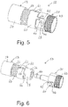
- connection device 58 that includes a suitable locking arrangement. Like and similar features are shown with like reference numerals.
- the connection device 58 includes a locking member 60, in this example a locking collar, mounted on the second cylindrical portion 26 of the first connection portion 18 and reciprocably movable relative to the second cylindrical portion 26.
- the locking member 60 includes an elongate guide aperture 61 that receives a guide pin 62 disposed on the second cylindrical portion 26.
- the guide aperture 61 and guide pin 62 cooperate to enable the locking collar to move reciprocably relative to the second cylindrical portion 26 whilst restraining rotation of the locking collar 60 relative to the second cylindrical portion 26.
- the locking member 60 is configured so as to engage with the second connection portion 20 so as to restrict rotation of the second connection portion 20 relative to the locking member 60 and thereby restrict rotation of the first and second connection portions 18, 20 relative to each other.
- relative rotation between the second connection portion 20 and the locking member 60 is restricted by providing the locking member 60 with a locking tab 66 disposed at a location such that the locking tab 66 is received in the longitudinal path portion 42 when the locking projection 28 is disposed in the locking position, as shown in Figure 5 .
- relative rotation between the second connection portion 20 and the locking member 60 is restricted by engagement between the locking tab 66 and the longitudinal path portion 42.
- the locking member 60 is movable between a first position wherein coil spring 64 is compressed, and during use the locking tab 66 is not engaged with the longitudinal path portion 42, and a second position wherein the coil spring is expanded, and during use the locking tab 66 is engaged with the longitudinal path portion 42.
- the locking member 60 is biased towards the second position, in this example using a coil spring 64.
- the first and second connection portions 18, 20 are first aligned such that the guide projection 50 aligns with the second cylindrical portion 26 and the locking projections 28 align with the longitudinal path portions 42.
- the first and second connection portions 18, 20 are then urged towards each other with the locking projections 28 moving through the longitudinal path portions 42.
- This causes the locking tab 66 to contact the second connection portion 20, and the locking member 60 to move from the second position towards the first position against the biasing force of the coil spring 64.
- the locking projections 28 reach the end of the longitudinal path portions 42, the user rotates the first and second connection portions 18, 20 relative to each other so that the locking projections 28 move through the transverse path portions 44.
- Rotation of the first and second connection portions 18, 20 relative to each other causes the second connection portion 20 to rotate relative to the locking member 60, and relative rotation continues until the locking tab 66 is aligned with the longitudinal path portion 42.
- the user allows the biasing force of the coil spring 64 to act on the locking member 60 to cause the locking tab 66 to be received in the longitudinal path portion 42, as shown in Figure 5 .
- Disengagement of the first and second connection portions 18, 20 from each other is achieved by first urging the locking member 60 to move away from the locking projections 28 against the biasing force of the coil spring 64 until the locking tab 66 is released from the longitudinal path portion 42. This allows the first and second connection portions 18, 20 to be rotated relative to each other and movement of the locking projection in the transverse path portion 44 to occur.
- connection device 12 that has a first connection portion 18 connected to a head assembly 14 and a second connection portion 20 connected to an inner tube 16
- first connection portion 18 is connected to the inner tube 16
- second connection portion 20 is connected to the head assembly 14.
Landscapes
- Engineering & Computer Science (AREA)
- General Engineering & Computer Science (AREA)
- Mechanical Engineering (AREA)
- Mining & Mineral Resources (AREA)
- Life Sciences & Earth Sciences (AREA)
- Geology (AREA)
- Environmental & Geological Engineering (AREA)
- Fluid Mechanics (AREA)
- Physics & Mathematics (AREA)
- General Life Sciences & Earth Sciences (AREA)
- Geochemistry & Mineralogy (AREA)
- Quick-Acting Or Multi-Walled Pipe Joints (AREA)
- Drilling Tools (AREA)
- Sampling And Sample Adjustment (AREA)
- Coupling Device And Connection With Printed Circuit (AREA)
- Sink And Installation For Waste Water (AREA)
Claims (7)
- Verbindungsvorrichtung (12) für eine Kernbohranordnung, wobei die Verbindungsvorrichtung (12) umfasst:einen ersten Verbindungsabschnitt (18) und einen zweiten Verbindungsabschnitt (20);wobei die Verbindungsvorrichtung (12) einen Verbindungsmechanismus einschließt, der eingerichtet ist, um das Eingreifen des ersten und zweiten Verbindungsabschnitts (18, 20) ineinander, und das Lösen des ersten und zweiten Verbindungsabschnitts (18, 20) voneinander zu erleichtern;wobei der Verbindungsmechanismus einschließt:mindestens einen Verriegelungsvorsprung (28), der am ersten Verbindungsabschnitt (18) angeordnet ist, und mindestens einen entsprechenden Verriegelungspfad (40), der am zweiten Verbindungsabschnitt (20) angeordnet ist, wobei der Verriegelungspfad (40) eine Verriegelungsstellung aufweist, derart, dass der erste und zweite Verbindungsabschnitt (18, 20) zusammengehalten werden, wenn ein Verriegelungsvorsprung (28) in der Verriegelungsstellung angeordnet ist, wobei jeder Verriegelungsvorsprung mit einem jeweiligen Verriegelungspfad (40) in Eingriff gebracht kann, und der Verriegelungspfad (40) derart eingerichtet ist, dass der Verriegelungsvorsprung (28) durch den Verriegelungspfad bewegt und in der Verriegelungsstellung aufgenommen werden kann, indem der erste und zweite Verbindungsabschnitt im Wesentlichen aufeinander zu bewegt und der erste und zweite Verbindungsabschnitt relativ zueinander gedreht werden;dadurch gekennzeichnet, dass der Verbindungsmechanismus weiter umfasst:
eine Verriegelungshülse (60), die derart am ersten Verbindungsabschnitt (18) angebracht ist, dass die Verriegelungshülse (60) relativ zu dem mindestens einen Verriegelungsvorsprung (28) hin- und herbewegt werden kann, und Drehung der Verriegelungshülse (60) relativ zu dem mindestens einen Verriegelungsvorsprung (28) einschränkt wird, wobei die Verriegelungshülse (60) eine Verriegelungsnase (66) einschließt; wobei die Verriegelungshülse (60), wenn der Verriegelungsvorsprung (28) in der Verriegelungsstellung angeordnet ist, hin- und herbewegt werden kann zwischen: einer ersten Stellung, in der die Verriegelungsnase (66) in den Verriegelungspfad (40) eingreift, sodass sie den ersten und zweiten Verbindungsabschnitt (18, 20) daran hindert, sich relativ zueinander zu drehen, und dadurch den Vorsprung (28) daran hindert, sich entlang mindestens eines Abschnitts des Verriegelungspfads (40) zu bewegen, und einer zweiten Stellung, in der die Verriegelungsnase (66) nicht in den Verriegelungspfad (40) eingreift und den ersten und zweiten Verbindungsabschnitt (18, 20) nicht daran hindert, sich relativ zueinander zu drehen, wodurch es dem Vorsprung (28) ermöglicht wird, sich entlang des Verriegelungspfads (40) zu bewegen; und wobei die Verriegelungshülse (60) elastisch zur ersten Stellung hin vorgespannt ist, derart, dass die Verriegelungshülse (60) den ersten und zweiten Verbindungsabschnitt (18, 20) elastisch auseinanderdrückt. - Verbindungsvorrichtung (12) nach Anspruch 1, wobei der Verriegelungspfad (40) im Allgemeinen L-förmig ist und einen längsverlaufenden Pfadabschnitt (42), der sich in einer im Wesentlichen parallelen Richtung zur Verbindungsvorrichtung (12) erstreckt, und einen querverlaufenden Pfadabschnitt (44) einschließt, der sich in einer im Allgemeinen querverlaufenden Richtung der Verbindungsvorrichtung (12) erstreckt.
- Verbindungsvorrichtung (12) nach Anspruch 2, wobei die Verriegelungsstellung von einem Senkenabschnitt (46) definiert wird, der mit dem querverlaufenden Pfadabschnitt (44) einstückig ist.
- Verbindungsvorrichtung (12) nach einem der vorstehenden Ansprüche, die ein erstes Vorspannelement (64) umfasst, das eingerichtet ist, um den ersten und zweiten Verbindungsabschnitt (18, 20) elastisch auseinander und dadurch den Vorsprung (28) zur Verriegelungsstellung hin vorzuspannen.
- Verbindungsvorrichtung (12) nach einem der vorstehenden Ansprüche, wobei die Verriegelungshülse (60) eine längliche Führungsöffnung (61) umfasst, und der erste Verbindungsabschnitt (18) einen Führungsstift (62) einschließt, der in der länglichen Führungsöffnung (61) aufgenommen ist, wobei der Führungsstift (62) und die Führungsöffnung (61) so zusammenwirken, dass Hin- und Herbewegung der Verriegelungshülse (60) relativ zum ersten Verbindungsabschnitt (18) erleichtert und Drehung der Verriegelungshülse (60) relativ zum ersten Verbindungsabschnitt (18) eingeschränkt wird.
- Verbindungsvorrichtung nach einem der vorstehenden Ansprüche, wobei der zweite Verbindungsabschnitt (20) einen Führungsvorsprung (50) einschließt, der eingerichtet ist, um Ausrichtung des ersten und zweiten Verbindungsabschnitts (18, 20) zu erleichtern, wenn der erste und zweite Verbindungsabschnitt (18, 20) während des Eingreifens des ersten Verbindungsabschnitts (18) in den zweiten Verbindungsabschnitt (20) aufeinander zu bewegt werden.
- Verbindungsvorrichtung (12) nach Anspruch 6, wobei der Führungsvorsprung (50) ein Durchgangsloch (52) einschließt, das eingerichtet ist, um Durchtritt von Fluid durch die Verbindungsvorrichtung (12) zu erleichtern, wenn die Verbindungsvorrichtung (12) im Gebrauch mit einer Kopfanordnung (14) und einem Innenrohr (16) der Kernbohranordnung verbunden ist.
Applications Claiming Priority (2)
| Application Number | Priority Date | Filing Date | Title |
|---|---|---|---|
| AU2015904625A AU2015904625A0 (en) | 2015-11-10 | A connection device | |
| PCT/AU2016/051081 WO2017079801A1 (en) | 2015-11-10 | 2016-11-10 | A connection device |
Publications (3)
| Publication Number | Publication Date |
|---|---|
| EP3374591A1 EP3374591A1 (de) | 2018-09-19 |
| EP3374591A4 EP3374591A4 (de) | 2019-07-03 |
| EP3374591B1 true EP3374591B1 (de) | 2020-10-14 |
Family
ID=58694535
Family Applications (1)
| Application Number | Title | Priority Date | Filing Date |
|---|---|---|---|
| EP16863235.4A Active EP3374591B1 (de) | 2015-11-10 | 2016-11-10 | Verbindungsvorrichtung |
Country Status (9)
| Country | Link |
|---|---|
| US (1) | US11168823B2 (de) |
| EP (1) | EP3374591B1 (de) |
| AU (2) | AU2016354672B2 (de) |
| BR (1) | BR112018009323B1 (de) |
| CL (1) | CL2018001233A1 (de) |
| ES (1) | ES2830264T3 (de) |
| PT (1) | PT3374591T (de) |
| WO (1) | WO2017079801A1 (de) |
| ZA (2) | ZA201802754B (de) |
Families Citing this family (20)
| Publication number | Priority date | Publication date | Assignee | Title |
|---|---|---|---|---|
| JPWO2015177901A1 (ja) * | 2014-05-22 | 2017-04-20 | 株式会社島津製作所 | カラム取付装置及びフェルールセット |
| US9644443B1 (en) | 2015-12-07 | 2017-05-09 | Fhe Usa Llc | Remotely-operated wellhead pressure control apparatus |
| JP6699625B2 (ja) * | 2017-05-31 | 2020-05-27 | 京セラドキュメントソリューションズ株式会社 | ジョイント機構及びこれを備えた画像形成装置 |
| WO2019068145A1 (en) * | 2017-10-03 | 2019-04-11 | Reflex Instruments Asia Pacific Pty Ltd | SYSTEM FOR ESTABLISHING A DOWNHILL DEVICE AND RELATED DRIVE TRANSFER AND METHOD FOR PROVIDING A DEVICE AT THE BACKGROUND OF A HOLE |
| AU2019221889A1 (en) | 2018-02-16 | 2020-08-27 | Flexidrill Limited | Pivot coupling |
| US12252949B2 (en) | 2018-03-28 | 2025-03-18 | Fhe Usa Llc | Fluid connection assembly with adapter release |
| US20190301260A1 (en) | 2018-03-28 | 2019-10-03 | Fhe Usa Llc | Remotely operated fluid connection |
| USD976092S1 (en) | 2019-06-24 | 2023-01-24 | Flexidrill Limited | Clevis |
| CN111577185B (zh) * | 2020-06-08 | 2023-08-15 | 四川大学 | 快接式中心杆拉取结构及分体式保真取芯器压力实验结构 |
| WO2022056469A1 (en) * | 2020-09-14 | 2022-03-17 | Aqseptence Group, Inc. | Anti-rotational pipe coupling |
| DE102021107006A1 (de) * | 2021-03-22 | 2022-09-22 | Fresenius Medical Care Deutschland Gmbh | Kopplungsvorrichtung |
| BR112023024950A2 (pt) | 2021-05-28 | 2024-02-15 | Engineered Controls Int Llc | Bico de baixa emissão e acoplamento de receptáculo para fluido criogênico |
| JP2023107577A (ja) * | 2022-01-24 | 2023-08-03 | 株式会社大林組 | 穿孔装置、着脱方法及びコアビット |
| EP4219073A1 (de) * | 2022-01-26 | 2023-08-02 | Monti-Werkzeuge GmbH | Rotativ antreibbare drehwerkzeugeinrichtung |
| KR102648828B1 (ko) * | 2022-03-30 | 2024-03-18 | 샘찬에너지(주) | 가스 충전 노즐 |
| KR102648827B1 (ko) * | 2022-03-30 | 2024-03-19 | 샘찬에너지(주) | 가스 충전 노즐 |
| US12496696B2 (en) | 2022-09-09 | 2025-12-16 | Techtronic Cordless Gp | Tool assembly and attachment apparatus for tool head |
| CN115635492B (zh) * | 2022-09-28 | 2025-05-13 | 河北大学 | 面向侦察救援任务的多功能剪式末端执行器及机械臂 |
| WO2024201261A1 (en) * | 2023-03-25 | 2024-10-03 | Hy-Tech Drilling Ltd. | Quick-release inner tube connection for core retrieval |
| US20250361899A1 (en) * | 2024-05-24 | 2025-11-27 | The Boeing Company | Twist-lock fasteners, assemblies, and methods for fastening |
Family Cites Families (18)
| Publication number | Priority date | Publication date | Assignee | Title |
|---|---|---|---|---|
| US765225A (en) * | 1904-03-18 | 1904-07-19 | Louis B Colin | Hose-coupling. |
| FR465921A (fr) * | 1913-07-18 | 1914-04-30 | Georges Rudolph | Perfectionnements aux joints d'accouplement des tuyaux, spécialement applicables aux tuyaux acoustiques |
| US1890011A (en) * | 1930-05-05 | 1932-12-06 | Wirz Henry | Coupling device |
| US2035887A (en) * | 1933-10-23 | 1936-03-31 | Globe Oil Tools Co | Valve for core barrels |
| US2240738A (en) * | 1937-07-14 | 1941-05-06 | Nat Supply Co | Rotary drilling rig |
| US3217746A (en) * | 1962-10-30 | 1965-11-16 | Brock Ind Inc | Fluid valve coupling with interlocking lugs |
| GB1194047A (en) * | 1967-08-29 | 1970-06-10 | John Joseph Mccarthy | Releasable Mechanical Coupling |
| US3253310A (en) * | 1965-05-04 | 1966-05-31 | Norco Inc | Releasable two-part fastener |
| FR1526167A (fr) * | 1967-04-10 | 1968-05-24 | Fenwick | Raccord à assemblage rapide du type dit à baoïonnette pour tuyauteries de fluide sous pression |
| US4679959A (en) * | 1986-10-16 | 1987-07-14 | The United States Of America As Represented By The Secretary Of The Army | Quick-connect/disconnect connector |
| WO1990012193A1 (de) | 1989-04-05 | 1990-10-18 | Geissler & Kuper Gesellschaft Mit Beschränkter Haftung Diamantwerkzeuge Maschinen | Anschlusskupplung für bohrmaschine mit staubabsaugung |
| AUPM681194A0 (en) | 1994-07-13 | 1994-08-04 | Expertest Pty. Ltd. | Quick connect coupling |
| US5660196A (en) * | 1995-12-20 | 1997-08-26 | Oven Systems, Inc. | Quick disconnect riser pipe assembly for can washer |
| US6102135A (en) * | 1997-12-11 | 2000-08-15 | Shaw; Neil B. | Portable core sampler |
| GB2332933B (en) * | 1998-01-05 | 2002-10-09 | Nat Coupling Co Inc | Locking device for undersea hydraulic coupling |
| CN1417450A (zh) * | 2002-11-18 | 2003-05-14 | 陈月辉 | 带间隙自动补偿的卡口连接机构 |
| JP2004169436A (ja) | 2002-11-21 | 2004-06-17 | Kyowa Kiso:Kk | 二重管掘削システム |
| US20070252386A1 (en) * | 2005-09-22 | 2007-11-01 | Cress Ronald J | Pressure tank fitting assembly |
-
2016
- 2016-11-10 AU AU2016354672A patent/AU2016354672B2/en active Active
- 2016-11-10 PT PT168632354T patent/PT3374591T/pt unknown
- 2016-11-10 ES ES16863235T patent/ES2830264T3/es active Active
- 2016-11-10 BR BR112018009323-8A patent/BR112018009323B1/pt active IP Right Grant
- 2016-11-10 EP EP16863235.4A patent/EP3374591B1/de active Active
- 2016-11-10 WO PCT/AU2016/051081 patent/WO2017079801A1/en not_active Ceased
-
2018
- 2018-04-25 ZA ZA2018/02754A patent/ZA201802754B/en unknown
- 2018-05-04 US US15/971,773 patent/US11168823B2/en active Active
- 2018-05-08 CL CL2018001233A patent/CL2018001233A1/es unknown
-
2021
- 2021-07-22 ZA ZA2021/05173A patent/ZA202105173B/en unknown
-
2022
- 2022-03-08 AU AU2022201614A patent/AU2022201614B2/en active Active
Non-Patent Citations (1)
| Title |
|---|
| None * |
Also Published As
| Publication number | Publication date |
|---|---|
| ZA202105173B (en) | 2024-01-31 |
| BR112018009323A8 (pt) | 2019-02-26 |
| EP3374591A4 (de) | 2019-07-03 |
| ZA201802754B (en) | 2022-09-28 |
| AU2016354672B2 (en) | 2021-12-09 |
| AU2022201614B2 (en) | 2023-10-12 |
| BR112018009323A2 (pt) | 2018-11-06 |
| AU2016354672A1 (en) | 2018-05-10 |
| PT3374591T (pt) | 2020-11-11 |
| US11168823B2 (en) | 2021-11-09 |
| WO2017079801A1 (en) | 2017-05-18 |
| CL2018001233A1 (es) | 2018-08-24 |
| ES2830264T3 (es) | 2021-06-03 |
| CA3004471A1 (en) | 2017-05-18 |
| BR112018009323B1 (pt) | 2022-11-01 |
| EP3374591A1 (de) | 2018-09-19 |
| AU2022201614A1 (en) | 2022-03-31 |
| US20180252052A1 (en) | 2018-09-06 |
Similar Documents
| Publication | Publication Date | Title |
|---|---|---|
| EP3374591B1 (de) | Verbindungsvorrichtung | |
| US6623220B2 (en) | Quick change mandrel assembly for use with a hole saw and a pilot drill bit | |
| US9144847B2 (en) | Cutter assembly | |
| US20170266771A1 (en) | Bolting tool and bolt mounting jig | |
| EP3568263B1 (de) | Drehmomentschlüssel und reaktionsarmanordnung | |
| US20160258489A1 (en) | Garden tool quick release device | |
| US20180320469A1 (en) | Tubing hanger orientation system and techniques | |
| US6997493B2 (en) | Lockable overshot | |
| US20140314505A1 (en) | Multi-position hole saw assembly with plug ejector | |
| EP2992173B1 (de) | Sicherheitsverriegelung für ein bohrlochwerkzeug | |
| CA3004471C (en) | A connection device | |
| US20220410289A1 (en) | Variable length tool holder | |
| HK1261029A1 (en) | A connection device | |
| HK1261029B (en) | A connection device | |
| OA18650A (en) | A connection device. | |
| US8813629B1 (en) | Positional lock for carrier assembly of breech-loaded weapon | |
| US8689891B2 (en) | Ball and dart launcher with parallel axis release | |
| US20090183351A1 (en) | Sewer lateral cap puller | |
| AU2002254799B2 (en) | Lockable overshot | |
| CN204603395U (zh) | 圆孔锯组件 | |
| AU2013200314A1 (en) | Pin-type coupling devices | |
| AU2002254799A1 (en) | Lockable overshot | |
| HK1170559A (en) | Method for coupling of a casing tube to a drill bit |
Legal Events
| Date | Code | Title | Description |
|---|---|---|---|
| STAA | Information on the status of an ep patent application or granted ep patent |
Free format text: STATUS: THE INTERNATIONAL PUBLICATION HAS BEEN MADE |
|
| PUAI | Public reference made under article 153(3) epc to a published international application that has entered the european phase |
Free format text: ORIGINAL CODE: 0009012 |
|
| STAA | Information on the status of an ep patent application or granted ep patent |
Free format text: STATUS: REQUEST FOR EXAMINATION WAS MADE |
|
| 17P | Request for examination filed |
Effective date: 20180425 |
|
| AK | Designated contracting states |
Kind code of ref document: A1 Designated state(s): AL AT BE BG CH CY CZ DE DK EE ES FI FR GB GR HR HU IE IS IT LI LT LU LV MC MK MT NL NO PL PT RO RS SE SI SK SM TR |
|
| AX | Request for extension of the european patent |
Extension state: BA ME |
|
| DAV | Request for validation of the european patent (deleted) | ||
| DAX | Request for extension of the european patent (deleted) | ||
| A4 | Supplementary search report drawn up and despatched |
Effective date: 20190604 |
|
| RIC1 | Information provided on ipc code assigned before grant |
Ipc: E21B 10/02 20060101ALI20190528BHEP Ipc: E21B 17/02 20060101AFI20190528BHEP Ipc: F16L 21/08 20060101ALI20190528BHEP Ipc: F16D 1/10 20060101ALI20190528BHEP Ipc: F16L 37/08 20060101ALI20190528BHEP Ipc: F16L 37/248 20060101ALI20190528BHEP Ipc: E21B 25/00 20060101ALI20190528BHEP Ipc: E21B 17/046 20060101ALI20190528BHEP Ipc: F16D 1/112 20060101ALI20190528BHEP |
|
| REG | Reference to a national code |
Ref country code: HK Ref legal event code: DE Ref document number: 1261029 Country of ref document: HK |
|
| GRAP | Despatch of communication of intention to grant a patent |
Free format text: ORIGINAL CODE: EPIDOSNIGR1 |
|
| STAA | Information on the status of an ep patent application or granted ep patent |
Free format text: STATUS: GRANT OF PATENT IS INTENDED |
|
| INTG | Intention to grant announced |
Effective date: 20200602 |
|
| GRAS | Grant fee paid |
Free format text: ORIGINAL CODE: EPIDOSNIGR3 |
|
| GRAA | (expected) grant |
Free format text: ORIGINAL CODE: 0009210 |
|
| STAA | Information on the status of an ep patent application or granted ep patent |
Free format text: STATUS: THE PATENT HAS BEEN GRANTED |
|
| AK | Designated contracting states |
Kind code of ref document: B1 Designated state(s): AL AT BE BG CH CY CZ DE DK EE ES FI FR GB GR HR HU IE IS IT LI LT LU LV MC MK MT NL NO PL PT RO RS SE SI SK SM TR |
|
| REG | Reference to a national code |
Ref country code: GB Ref legal event code: FG4D |
|
| REG | Reference to a national code |
Ref country code: AT Ref legal event code: REF Ref document number: 1323759 Country of ref document: AT Kind code of ref document: T Effective date: 20201015 Ref country code: CH Ref legal event code: EP |
|
| REG | Reference to a national code |
Ref country code: DE Ref legal event code: R096 Ref document number: 602016046013 Country of ref document: DE |
|
| REG | Reference to a national code |
Ref country code: FI Ref legal event code: FGE |
|
| REG | Reference to a national code |
Ref country code: PT Ref legal event code: SC4A Ref document number: 3374591 Country of ref document: PT Date of ref document: 20201111 Kind code of ref document: T Free format text: AVAILABILITY OF NATIONAL TRANSLATION Effective date: 20201104 Ref country code: IE Ref legal event code: FG4D |
|
| REG | Reference to a national code |
Ref country code: SE Ref legal event code: TRGR |
|
| REG | Reference to a national code |
Ref country code: AT Ref legal event code: MK05 Ref document number: 1323759 Country of ref document: AT Kind code of ref document: T Effective date: 20201014 |
|
| REG | Reference to a national code |
Ref country code: NL Ref legal event code: MP Effective date: 20201014 |
|
| PG25 | Lapsed in a contracting state [announced via postgrant information from national office to epo] |
Ref country code: NO Free format text: LAPSE BECAUSE OF FAILURE TO SUBMIT A TRANSLATION OF THE DESCRIPTION OR TO PAY THE FEE WITHIN THE PRESCRIBED TIME-LIMIT Effective date: 20210114 Ref country code: RS Free format text: LAPSE BECAUSE OF FAILURE TO SUBMIT A TRANSLATION OF THE DESCRIPTION OR TO PAY THE FEE WITHIN THE PRESCRIBED TIME-LIMIT Effective date: 20201014 Ref country code: GR Free format text: LAPSE BECAUSE OF FAILURE TO SUBMIT A TRANSLATION OF THE DESCRIPTION OR TO PAY THE FEE WITHIN THE PRESCRIBED TIME-LIMIT Effective date: 20210115 |
|
| REG | Reference to a national code |
Ref country code: LT Ref legal event code: MG4D |
|
| PG25 | Lapsed in a contracting state [announced via postgrant information from national office to epo] |
Ref country code: AT Free format text: LAPSE BECAUSE OF FAILURE TO SUBMIT A TRANSLATION OF THE DESCRIPTION OR TO PAY THE FEE WITHIN THE PRESCRIBED TIME-LIMIT Effective date: 20201014 Ref country code: BG Free format text: LAPSE BECAUSE OF FAILURE TO SUBMIT A TRANSLATION OF THE DESCRIPTION OR TO PAY THE FEE WITHIN THE PRESCRIBED TIME-LIMIT Effective date: 20210114 Ref country code: PL Free format text: LAPSE BECAUSE OF FAILURE TO SUBMIT A TRANSLATION OF THE DESCRIPTION OR TO PAY THE FEE WITHIN THE PRESCRIBED TIME-LIMIT Effective date: 20201014 Ref country code: LV Free format text: LAPSE BECAUSE OF FAILURE TO SUBMIT A TRANSLATION OF THE DESCRIPTION OR TO PAY THE FEE WITHIN THE PRESCRIBED TIME-LIMIT Effective date: 20201014 Ref country code: IS Free format text: LAPSE BECAUSE OF FAILURE TO SUBMIT A TRANSLATION OF THE DESCRIPTION OR TO PAY THE FEE WITHIN THE PRESCRIBED TIME-LIMIT Effective date: 20210214 |
|
| REG | Reference to a national code |
Ref country code: DE Ref legal event code: R119 Ref document number: 602016046013 Country of ref document: DE |
|
| REG | Reference to a national code |
Ref country code: ES Ref legal event code: FG2A Ref document number: 2830264 Country of ref document: ES Kind code of ref document: T3 Effective date: 20210603 |
|
| PG25 | Lapsed in a contracting state [announced via postgrant information from national office to epo] |
Ref country code: NL Free format text: LAPSE BECAUSE OF FAILURE TO SUBMIT A TRANSLATION OF THE DESCRIPTION OR TO PAY THE FEE WITHIN THE PRESCRIBED TIME-LIMIT Effective date: 20201014 Ref country code: HR Free format text: LAPSE BECAUSE OF FAILURE TO SUBMIT A TRANSLATION OF THE DESCRIPTION OR TO PAY THE FEE WITHIN THE PRESCRIBED TIME-LIMIT Effective date: 20201014 |
|
| REG | Reference to a national code |
Ref country code: CH Ref legal event code: PL |
|
| PG25 | Lapsed in a contracting state [announced via postgrant information from national office to epo] |
Ref country code: RO Free format text: LAPSE BECAUSE OF FAILURE TO SUBMIT A TRANSLATION OF THE DESCRIPTION OR TO PAY THE FEE WITHIN THE PRESCRIBED TIME-LIMIT Effective date: 20201014 Ref country code: SK Free format text: LAPSE BECAUSE OF FAILURE TO SUBMIT A TRANSLATION OF THE DESCRIPTION OR TO PAY THE FEE WITHIN THE PRESCRIBED TIME-LIMIT Effective date: 20201014 Ref country code: CZ Free format text: LAPSE BECAUSE OF FAILURE TO SUBMIT A TRANSLATION OF THE DESCRIPTION OR TO PAY THE FEE WITHIN THE PRESCRIBED TIME-LIMIT Effective date: 20201014 Ref country code: EE Free format text: LAPSE BECAUSE OF FAILURE TO SUBMIT A TRANSLATION OF THE DESCRIPTION OR TO PAY THE FEE WITHIN THE PRESCRIBED TIME-LIMIT Effective date: 20201014 Ref country code: SM Free format text: LAPSE BECAUSE OF FAILURE TO SUBMIT A TRANSLATION OF THE DESCRIPTION OR TO PAY THE FEE WITHIN THE PRESCRIBED TIME-LIMIT Effective date: 20201014 Ref country code: LT Free format text: LAPSE BECAUSE OF FAILURE TO SUBMIT A TRANSLATION OF THE DESCRIPTION OR TO PAY THE FEE WITHIN THE PRESCRIBED TIME-LIMIT Effective date: 20201014 Ref country code: MC Free format text: LAPSE BECAUSE OF FAILURE TO SUBMIT A TRANSLATION OF THE DESCRIPTION OR TO PAY THE FEE WITHIN THE PRESCRIBED TIME-LIMIT Effective date: 20201014 Ref country code: LU Free format text: LAPSE BECAUSE OF NON-PAYMENT OF DUE FEES Effective date: 20201110 |
|
| REG | Reference to a national code |
Ref country code: BE Ref legal event code: MM Effective date: 20201130 |
|
| PLBE | No opposition filed within time limit |
Free format text: ORIGINAL CODE: 0009261 |
|
| STAA | Information on the status of an ep patent application or granted ep patent |
Free format text: STATUS: NO OPPOSITION FILED WITHIN TIME LIMIT |
|
| PG25 | Lapsed in a contracting state [announced via postgrant information from national office to epo] |
Ref country code: LI Free format text: LAPSE BECAUSE OF NON-PAYMENT OF DUE FEES Effective date: 20201130 Ref country code: CH Free format text: LAPSE BECAUSE OF NON-PAYMENT OF DUE FEES Effective date: 20201130 Ref country code: DK Free format text: LAPSE BECAUSE OF FAILURE TO SUBMIT A TRANSLATION OF THE DESCRIPTION OR TO PAY THE FEE WITHIN THE PRESCRIBED TIME-LIMIT Effective date: 20201014 |
|
| 26N | No opposition filed |
Effective date: 20210715 |
|
| GBPC | Gb: european patent ceased through non-payment of renewal fee |
Effective date: 20210114 |
|
| PG25 | Lapsed in a contracting state [announced via postgrant information from national office to epo] |
Ref country code: IE Free format text: LAPSE BECAUSE OF NON-PAYMENT OF DUE FEES Effective date: 20201110 Ref country code: AL Free format text: LAPSE BECAUSE OF FAILURE TO SUBMIT A TRANSLATION OF THE DESCRIPTION OR TO PAY THE FEE WITHIN THE PRESCRIBED TIME-LIMIT Effective date: 20201014 Ref country code: FR Free format text: LAPSE BECAUSE OF NON-PAYMENT OF DUE FEES Effective date: 20201214 Ref country code: IT Free format text: LAPSE BECAUSE OF FAILURE TO SUBMIT A TRANSLATION OF THE DESCRIPTION OR TO PAY THE FEE WITHIN THE PRESCRIBED TIME-LIMIT Effective date: 20201014 |
|
| PG25 | Lapsed in a contracting state [announced via postgrant information from national office to epo] |
Ref country code: GB Free format text: LAPSE BECAUSE OF NON-PAYMENT OF DUE FEES Effective date: 20210114 Ref country code: SI Free format text: LAPSE BECAUSE OF FAILURE TO SUBMIT A TRANSLATION OF THE DESCRIPTION OR TO PAY THE FEE WITHIN THE PRESCRIBED TIME-LIMIT Effective date: 20201014 Ref country code: DE Free format text: LAPSE BECAUSE OF NON-PAYMENT OF DUE FEES Effective date: 20210601 |
|
| PG25 | Lapsed in a contracting state [announced via postgrant information from national office to epo] |
Ref country code: IS Free format text: LAPSE BECAUSE OF FAILURE TO SUBMIT A TRANSLATION OF THE DESCRIPTION OR TO PAY THE FEE WITHIN THE PRESCRIBED TIME-LIMIT Effective date: 20210214 Ref country code: TR Free format text: LAPSE BECAUSE OF FAILURE TO SUBMIT A TRANSLATION OF THE DESCRIPTION OR TO PAY THE FEE WITHIN THE PRESCRIBED TIME-LIMIT Effective date: 20201014 Ref country code: MT Free format text: LAPSE BECAUSE OF FAILURE TO SUBMIT A TRANSLATION OF THE DESCRIPTION OR TO PAY THE FEE WITHIN THE PRESCRIBED TIME-LIMIT Effective date: 20201014 Ref country code: CY Free format text: LAPSE BECAUSE OF FAILURE TO SUBMIT A TRANSLATION OF THE DESCRIPTION OR TO PAY THE FEE WITHIN THE PRESCRIBED TIME-LIMIT Effective date: 20201014 |
|
| PG25 | Lapsed in a contracting state [announced via postgrant information from national office to epo] |
Ref country code: MK Free format text: LAPSE BECAUSE OF FAILURE TO SUBMIT A TRANSLATION OF THE DESCRIPTION OR TO PAY THE FEE WITHIN THE PRESCRIBED TIME-LIMIT Effective date: 20201014 |
|
| PG25 | Lapsed in a contracting state [announced via postgrant information from national office to epo] |
Ref country code: BE Free format text: LAPSE BECAUSE OF NON-PAYMENT OF DUE FEES Effective date: 20201130 |
|
| PGFP | Annual fee paid to national office [announced via postgrant information from national office to epo] |
Ref country code: PT Payment date: 20251030 Year of fee payment: 10 |
|
| PGFP | Annual fee paid to national office [announced via postgrant information from national office to epo] |
Ref country code: FI Payment date: 20251125 Year of fee payment: 10 |
|
| PGFP | Annual fee paid to national office [announced via postgrant information from national office to epo] |
Ref country code: SE Payment date: 20251119 Year of fee payment: 10 |
|
| PGFP | Annual fee paid to national office [announced via postgrant information from national office to epo] |
Ref country code: ES Payment date: 20251229 Year of fee payment: 10 |