EP3374419B1 - Method for treating an elastomer packaging element, and packaging element thus treated - Google Patents
Method for treating an elastomer packaging element, and packaging element thus treated Download PDFInfo
- Publication number
- EP3374419B1 EP3374419B1 EP16819592.3A EP16819592A EP3374419B1 EP 3374419 B1 EP3374419 B1 EP 3374419B1 EP 16819592 A EP16819592 A EP 16819592A EP 3374419 B1 EP3374419 B1 EP 3374419B1
- Authority
- EP
- European Patent Office
- Prior art keywords
- plasma
- top surface
- advantageously
- activation
- cycles
- Prior art date
- Legal status (The legal status is an assumption and is not a legal conclusion. Google has not performed a legal analysis and makes no representation as to the accuracy of the status listed.)
- Active
Links
- 238000000034 method Methods 0.000 title claims description 32
- 229920001971 elastomer Polymers 0.000 title claims description 20
- 238000004806 packaging method and process Methods 0.000 title claims description 20
- 239000000806 elastomer Substances 0.000 title claims 3
- IJGRMHOSHXDMSA-UHFFFAOYSA-N Atomic nitrogen Chemical compound N#N IJGRMHOSHXDMSA-UHFFFAOYSA-N 0.000 claims description 24
- 230000004913 activation Effects 0.000 claims description 21
- 239000003570 air Substances 0.000 claims description 13
- 239000007789 gas Substances 0.000 claims description 13
- 229910052757 nitrogen Inorganic materials 0.000 claims description 12
- 239000011248 coating agent Substances 0.000 claims description 11
- 238000000576 coating method Methods 0.000 claims description 11
- XKRFYHLGVUSROY-UHFFFAOYSA-N Argon Chemical compound [Ar] XKRFYHLGVUSROY-UHFFFAOYSA-N 0.000 claims description 10
- 239000000178 monomer Substances 0.000 claims description 10
- 230000008021 deposition Effects 0.000 claims description 8
- UHOVQNZJYSORNB-UHFFFAOYSA-N Benzene Chemical group C1=CC=CC=C1 UHOVQNZJYSORNB-UHFFFAOYSA-N 0.000 claims description 6
- 229920001780 ECTFE Polymers 0.000 claims description 6
- QVGXLLKOCUKJST-UHFFFAOYSA-N atomic oxygen Chemical compound [O] QVGXLLKOCUKJST-UHFFFAOYSA-N 0.000 claims description 6
- 229920000840 ethylene tetrafluoroethylene copolymer Polymers 0.000 claims description 6
- 239000001301 oxygen Substances 0.000 claims description 6
- 229910052760 oxygen Inorganic materials 0.000 claims description 6
- 229920001343 polytetrafluoroethylene Polymers 0.000 claims description 6
- 239000004810 polytetrafluoroethylene Substances 0.000 claims description 6
- 229910052786 argon Inorganic materials 0.000 claims description 5
- 239000001307 helium Substances 0.000 claims description 5
- 229910052734 helium Inorganic materials 0.000 claims description 5
- SWQJXJOGLNCZEY-UHFFFAOYSA-N helium atom Chemical compound [He] SWQJXJOGLNCZEY-UHFFFAOYSA-N 0.000 claims description 5
- 238000006116 polymerization reaction Methods 0.000 claims description 5
- -1 siloxanes Chemical class 0.000 claims description 5
- VVJKKWFAADXIJK-UHFFFAOYSA-N Allylamine Chemical group NCC=C VVJKKWFAADXIJK-UHFFFAOYSA-N 0.000 claims description 4
- JUJWROOIHBZHMG-UHFFFAOYSA-N Pyridine Chemical group C1=CC=NC=C1 JUJWROOIHBZHMG-UHFFFAOYSA-N 0.000 claims description 4
- PPBRXRYQALVLMV-UHFFFAOYSA-N Styrene Chemical group C=CC1=CC=CC=C1 PPBRXRYQALVLMV-UHFFFAOYSA-N 0.000 claims description 4
- VNWKTOKETHGBQD-UHFFFAOYSA-N methane Chemical group C VNWKTOKETHGBQD-UHFFFAOYSA-N 0.000 claims description 4
- CHJAYYWUZLWNSQ-UHFFFAOYSA-N 1-chloro-1,2,2-trifluoroethene;ethene Chemical group C=C.FC(F)=C(F)Cl CHJAYYWUZLWNSQ-UHFFFAOYSA-N 0.000 claims description 3
- 239000004812 Fluorinated ethylene propylene Substances 0.000 claims description 3
- QHSJIZLJUFMIFP-UHFFFAOYSA-N ethene;1,1,2,2-tetrafluoroethene Chemical group C=C.FC(F)=C(F)F QHSJIZLJUFMIFP-UHFFFAOYSA-N 0.000 claims description 3
- HQQADJVZYDDRJT-UHFFFAOYSA-N ethene;prop-1-ene Chemical group C=C.CC=C HQQADJVZYDDRJT-UHFFFAOYSA-N 0.000 claims description 3
- 229920009441 perflouroethylene propylene Polymers 0.000 claims description 3
- 239000002210 silicon-based material Substances 0.000 claims description 3
- SMZOUWXMTYCWNB-UHFFFAOYSA-N 2-(2-methoxy-5-methylphenyl)ethanamine Chemical group COC1=CC=C(C)C=C1CCN SMZOUWXMTYCWNB-UHFFFAOYSA-N 0.000 claims description 2
- NIXOWILDQLNWCW-UHFFFAOYSA-N 2-Propenoic acid Chemical group OC(=O)C=C NIXOWILDQLNWCW-UHFFFAOYSA-N 0.000 claims description 2
- KGIGUEBEKRSTEW-UHFFFAOYSA-N 2-vinylpyridine Chemical group C=CC1=CC=CC=N1 KGIGUEBEKRSTEW-UHFFFAOYSA-N 0.000 claims description 2
- OTMSDBZUPAUEDD-UHFFFAOYSA-N Ethane Chemical group CC OTMSDBZUPAUEDD-UHFFFAOYSA-N 0.000 claims description 2
- VGGSQFUCUMXWEO-UHFFFAOYSA-N Ethene Chemical group C=C VGGSQFUCUMXWEO-UHFFFAOYSA-N 0.000 claims description 2
- 239000005977 Ethylene Chemical group 0.000 claims description 2
- HSFWRNGVRCDJHI-UHFFFAOYSA-N alpha-acetylene Chemical group C#C HSFWRNGVRCDJHI-UHFFFAOYSA-N 0.000 claims description 2
- 125000002534 ethynyl group Chemical group [H]C#C* 0.000 claims description 2
- NBVXSUQYWXRMNV-UHFFFAOYSA-N fluoromethane Chemical group FC NBVXSUQYWXRMNV-UHFFFAOYSA-N 0.000 claims description 2
- VBZWSGALLODQNC-UHFFFAOYSA-N hexafluoroacetone Chemical compound FC(F)(F)C(=O)C(F)(F)F VBZWSGALLODQNC-UHFFFAOYSA-N 0.000 claims description 2
- UMJSCPRVCHMLSP-UHFFFAOYSA-N pyridine Chemical group COC1=CC=CN=C1 UMJSCPRVCHMLSP-UHFFFAOYSA-N 0.000 claims description 2
- 229920006395 saturated elastomer Polymers 0.000 claims description 2
- 150000004756 silanes Chemical class 0.000 claims description 2
- BFKJFAAPBSQJPD-UHFFFAOYSA-N tetrafluoroethene Chemical group FC(F)=C(F)F BFKJFAAPBSQJPD-UHFFFAOYSA-N 0.000 claims description 2
- TXEYQDLBPFQVAA-UHFFFAOYSA-N tetrafluoromethane Chemical compound FC(F)(F)F TXEYQDLBPFQVAA-UHFFFAOYSA-N 0.000 claims description 2
- 230000000379 polymerizing effect Effects 0.000 claims 2
- 229930195733 hydrocarbon Natural products 0.000 claims 1
- 150000002430 hydrocarbons Chemical class 0.000 claims 1
- 239000005060 rubber Substances 0.000 description 17
- 239000000758 substrate Substances 0.000 description 11
- 239000003814 drug Substances 0.000 description 10
- 229940079593 drug Drugs 0.000 description 10
- 230000008569 process Effects 0.000 description 9
- RRHGJUQNOFWUDK-UHFFFAOYSA-N Isoprene Chemical compound CC(=C)C=C RRHGJUQNOFWUDK-UHFFFAOYSA-N 0.000 description 8
- 229920001195 polyisoprene Polymers 0.000 description 8
- 238000005516 engineering process Methods 0.000 description 7
- 230000004888 barrier function Effects 0.000 description 6
- 238000000151 deposition Methods 0.000 description 6
- 238000004519 manufacturing process Methods 0.000 description 6
- 230000005012 migration Effects 0.000 description 6
- 238000013508 migration Methods 0.000 description 6
- 238000003780 insertion Methods 0.000 description 5
- 230000037431 insertion Effects 0.000 description 5
- 229920002545 silicone oil Polymers 0.000 description 5
- 230000008901 benefit Effects 0.000 description 4
- 229920002313 fluoropolymer Polymers 0.000 description 4
- 229920001296 polysiloxane Polymers 0.000 description 4
- 238000012545 processing Methods 0.000 description 4
- 239000000126 substance Substances 0.000 description 4
- 239000004811 fluoropolymer Substances 0.000 description 3
- 229920000642 polymer Polymers 0.000 description 3
- 239000002904 solvent Substances 0.000 description 3
- 239000003795 chemical substances by application Substances 0.000 description 2
- 230000003750 conditioning effect Effects 0.000 description 2
- 239000003431 cross linking reagent Substances 0.000 description 2
- 238000009434 installation Methods 0.000 description 2
- 239000000463 material Substances 0.000 description 2
- 229920006254 polymer film Polymers 0.000 description 2
- KRQUFUKTQHISJB-YYADALCUSA-N 2-[(E)-N-[2-(4-chlorophenoxy)propoxy]-C-propylcarbonimidoyl]-3-hydroxy-5-(thian-3-yl)cyclohex-2-en-1-one Chemical compound CCC\C(=N/OCC(C)OC1=CC=C(Cl)C=C1)C1=C(O)CC(CC1=O)C1CCCSC1 KRQUFUKTQHISJB-YYADALCUSA-N 0.000 description 1
- 238000006677 Appel reaction Methods 0.000 description 1
- 241001644893 Entandrophragma utile Species 0.000 description 1
- KRHYYFGTRYWZRS-UHFFFAOYSA-M Fluoride anion Chemical compound [F-] KRHYYFGTRYWZRS-UHFFFAOYSA-M 0.000 description 1
- 239000000654 additive Substances 0.000 description 1
- 239000002318 adhesion promoter Substances 0.000 description 1
- 230000000181 anti-adherent effect Effects 0.000 description 1
- 239000003911 antiadherent Substances 0.000 description 1
- 239000003963 antioxidant agent Substances 0.000 description 1
- 229920005549 butyl rubber Polymers 0.000 description 1
- 238000006243 chemical reaction Methods 0.000 description 1
- 230000005495 cold plasma Effects 0.000 description 1
- 230000001419 dependent effect Effects 0.000 description 1
- 238000011161 development Methods 0.000 description 1
- 238000010586 diagram Methods 0.000 description 1
- KPUWHANPEXNPJT-UHFFFAOYSA-N disiloxane Chemical class [SiH3]O[SiH3] KPUWHANPEXNPJT-UHFFFAOYSA-N 0.000 description 1
- 230000000694 effects Effects 0.000 description 1
- 239000000839 emulsion Substances 0.000 description 1
- 230000007613 environmental effect Effects 0.000 description 1
- 239000012530 fluid Substances 0.000 description 1
- 239000011261 inert gas Substances 0.000 description 1
- 229910052500 inorganic mineral Inorganic materials 0.000 description 1
- 230000002452 interceptive effect Effects 0.000 description 1
- 150000002500 ions Chemical class 0.000 description 1
- 239000000314 lubricant Substances 0.000 description 1
- 239000011707 mineral Substances 0.000 description 1
- 238000000465 moulding Methods 0.000 description 1
- 239000003921 oil Substances 0.000 description 1
- 239000003960 organic solvent Substances 0.000 description 1
- 239000002245 particle Substances 0.000 description 1
- 230000035699 permeability Effects 0.000 description 1
- 238000002360 preparation method Methods 0.000 description 1
- 238000003672 processing method Methods 0.000 description 1
- 102000004169 proteins and genes Human genes 0.000 description 1
- 108090000623 proteins and genes Proteins 0.000 description 1
- 238000005086 pumping Methods 0.000 description 1
- 239000002994 raw material Substances 0.000 description 1
- 238000004064 recycling Methods 0.000 description 1
- 239000013557 residual solvent Substances 0.000 description 1
- 229930195734 saturated hydrocarbon Natural products 0.000 description 1
- 239000007921 spray Substances 0.000 description 1
- 238000003860 storage Methods 0.000 description 1
- 231100000331 toxic Toxicity 0.000 description 1
- 231100000167 toxic agent Toxicity 0.000 description 1
- 230000002588 toxic effect Effects 0.000 description 1
- 239000003440 toxic substance Substances 0.000 description 1
- 231100000419 toxicity Toxicity 0.000 description 1
- 230000001988 toxicity Effects 0.000 description 1
- 229930195735 unsaturated hydrocarbon Natural products 0.000 description 1
- 238000004073 vulcanization Methods 0.000 description 1
- 238000005406 washing Methods 0.000 description 1
Images
Classifications
-
- C—CHEMISTRY; METALLURGY
- C08—ORGANIC MACROMOLECULAR COMPOUNDS; THEIR PREPARATION OR CHEMICAL WORKING-UP; COMPOSITIONS BASED THEREON
- C08J—WORKING-UP; GENERAL PROCESSES OF COMPOUNDING; AFTER-TREATMENT NOT COVERED BY SUBCLASSES C08B, C08C, C08F, C08G or C08H
- C08J7/00—Chemical treatment or coating of shaped articles made of macromolecular substances
- C08J7/12—Chemical modification
- C08J7/16—Chemical modification with polymerisable compounds
- C08J7/18—Chemical modification with polymerisable compounds using wave energy or particle radiation
-
- C—CHEMISTRY; METALLURGY
- C08—ORGANIC MACROMOLECULAR COMPOUNDS; THEIR PREPARATION OR CHEMICAL WORKING-UP; COMPOSITIONS BASED THEREON
- C08J—WORKING-UP; GENERAL PROCESSES OF COMPOUNDING; AFTER-TREATMENT NOT COVERED BY SUBCLASSES C08B, C08C, C08F, C08G or C08H
- C08J7/00—Chemical treatment or coating of shaped articles made of macromolecular substances
- C08J7/12—Chemical modification
- C08J7/123—Treatment by wave energy or particle radiation
-
- A—HUMAN NECESSITIES
- A61—MEDICAL OR VETERINARY SCIENCE; HYGIENE
- A61J—CONTAINERS SPECIALLY ADAPTED FOR MEDICAL OR PHARMACEUTICAL PURPOSES; DEVICES OR METHODS SPECIALLY ADAPTED FOR BRINGING PHARMACEUTICAL PRODUCTS INTO PARTICULAR PHYSICAL OR ADMINISTERING FORMS; DEVICES FOR ADMINISTERING FOOD OR MEDICINES ORALLY; BABY COMFORTERS; DEVICES FOR RECEIVING SPITTLE
- A61J1/00—Containers specially adapted for medical or pharmaceutical purposes
- A61J1/14—Details; Accessories therefor
- A61J1/1412—Containers with closing means, e.g. caps
-
- B—PERFORMING OPERATIONS; TRANSPORTING
- B05—SPRAYING OR ATOMISING IN GENERAL; APPLYING FLUENT MATERIALS TO SURFACES, IN GENERAL
- B05D—PROCESSES FOR APPLYING FLUENT MATERIALS TO SURFACES, IN GENERAL
- B05D1/00—Processes for applying liquids or other fluent materials
- B05D1/62—Plasma-deposition of organic layers
-
- B—PERFORMING OPERATIONS; TRANSPORTING
- B05—SPRAYING OR ATOMISING IN GENERAL; APPLYING FLUENT MATERIALS TO SURFACES, IN GENERAL
- B05D—PROCESSES FOR APPLYING FLUENT MATERIALS TO SURFACES, IN GENERAL
- B05D3/00—Pretreatment of surfaces to which liquids or other fluent materials are to be applied; After-treatment of applied coatings, e.g. intermediate treating of an applied coating preparatory to subsequent applications of liquids or other fluent materials
- B05D3/14—Pretreatment of surfaces to which liquids or other fluent materials are to be applied; After-treatment of applied coatings, e.g. intermediate treating of an applied coating preparatory to subsequent applications of liquids or other fluent materials by electrical means
- B05D3/141—Plasma treatment
- B05D3/142—Pretreatment
- B05D3/144—Pretreatment of polymeric substrates
-
- B—PERFORMING OPERATIONS; TRANSPORTING
- B65—CONVEYING; PACKING; STORING; HANDLING THIN OR FILAMENTARY MATERIAL
- B65D—CONTAINERS FOR STORAGE OR TRANSPORT OF ARTICLES OR MATERIALS, e.g. BAGS, BARRELS, BOTTLES, BOXES, CANS, CARTONS, CRATES, DRUMS, JARS, TANKS, HOPPERS, FORWARDING CONTAINERS; ACCESSORIES, CLOSURES, OR FITTINGS THEREFOR; PACKAGING ELEMENTS; PACKAGES
- B65D39/00—Closures arranged within necks or pouring openings or in discharge apertures, e.g. stoppers
- B65D39/0005—Closures arranged within necks or pouring openings or in discharge apertures, e.g. stoppers made in one piece
-
- C—CHEMISTRY; METALLURGY
- C08—ORGANIC MACROMOLECULAR COMPOUNDS; THEIR PREPARATION OR CHEMICAL WORKING-UP; COMPOSITIONS BASED THEREON
- C08F—MACROMOLECULAR COMPOUNDS OBTAINED BY REACTIONS ONLY INVOLVING CARBON-TO-CARBON UNSATURATED BONDS
- C08F2/00—Processes of polymerisation
- C08F2/46—Polymerisation initiated by wave energy or particle radiation
- C08F2/52—Polymerisation initiated by wave energy or particle radiation by electric discharge, e.g. voltolisation
-
- C—CHEMISTRY; METALLURGY
- C08—ORGANIC MACROMOLECULAR COMPOUNDS; THEIR PREPARATION OR CHEMICAL WORKING-UP; COMPOSITIONS BASED THEREON
- C08L—COMPOSITIONS OF MACROMOLECULAR COMPOUNDS
- C08L27/00—Compositions of homopolymers or copolymers of compounds having one or more unsaturated aliphatic radicals, each having only one carbon-to-carbon double bond, and at least one being terminated by a halogen; Compositions of derivatives of such polymers
- C08L27/02—Compositions of homopolymers or copolymers of compounds having one or more unsaturated aliphatic radicals, each having only one carbon-to-carbon double bond, and at least one being terminated by a halogen; Compositions of derivatives of such polymers not modified by chemical after-treatment
- C08L27/12—Compositions of homopolymers or copolymers of compounds having one or more unsaturated aliphatic radicals, each having only one carbon-to-carbon double bond, and at least one being terminated by a halogen; Compositions of derivatives of such polymers not modified by chemical after-treatment containing fluorine atoms
-
- C—CHEMISTRY; METALLURGY
- C08—ORGANIC MACROMOLECULAR COMPOUNDS; THEIR PREPARATION OR CHEMICAL WORKING-UP; COMPOSITIONS BASED THEREON
- C08F—MACROMOLECULAR COMPOUNDS OBTAINED BY REACTIONS ONLY INVOLVING CARBON-TO-CARBON UNSATURATED BONDS
- C08F14/00—Homopolymers and copolymers of compounds having one or more unsaturated aliphatic radicals, each having only one carbon-to-carbon double bond, and at least one being terminated by a halogen
- C08F14/18—Monomers containing fluorine
- C08F14/24—Trifluorochloroethene
-
- C—CHEMISTRY; METALLURGY
- C08—ORGANIC MACROMOLECULAR COMPOUNDS; THEIR PREPARATION OR CHEMICAL WORKING-UP; COMPOSITIONS BASED THEREON
- C08F—MACROMOLECULAR COMPOUNDS OBTAINED BY REACTIONS ONLY INVOLVING CARBON-TO-CARBON UNSATURATED BONDS
- C08F14/00—Homopolymers and copolymers of compounds having one or more unsaturated aliphatic radicals, each having only one carbon-to-carbon double bond, and at least one being terminated by a halogen
- C08F14/18—Monomers containing fluorine
- C08F14/26—Tetrafluoroethene
-
- C—CHEMISTRY; METALLURGY
- C08—ORGANIC MACROMOLECULAR COMPOUNDS; THEIR PREPARATION OR CHEMICAL WORKING-UP; COMPOSITIONS BASED THEREON
- C08F—MACROMOLECULAR COMPOUNDS OBTAINED BY REACTIONS ONLY INVOLVING CARBON-TO-CARBON UNSATURATED BONDS
- C08F36/00—Homopolymers and copolymers of compounds having one or more unsaturated aliphatic radicals, at least one having two or more carbon-to-carbon double bonds
- C08F36/02—Homopolymers and copolymers of compounds having one or more unsaturated aliphatic radicals, at least one having two or more carbon-to-carbon double bonds the radical having only two carbon-to-carbon double bonds
- C08F36/04—Homopolymers and copolymers of compounds having one or more unsaturated aliphatic radicals, at least one having two or more carbon-to-carbon double bonds the radical having only two carbon-to-carbon double bonds conjugated
- C08F36/14—Homopolymers and copolymers of compounds having one or more unsaturated aliphatic radicals, at least one having two or more carbon-to-carbon double bonds the radical having only two carbon-to-carbon double bonds conjugated containing elements other than carbon and hydrogen
- C08F36/16—Homopolymers and copolymers of compounds having one or more unsaturated aliphatic radicals, at least one having two or more carbon-to-carbon double bonds the radical having only two carbon-to-carbon double bonds conjugated containing elements other than carbon and hydrogen containing halogen
-
- C—CHEMISTRY; METALLURGY
- C08—ORGANIC MACROMOLECULAR COMPOUNDS; THEIR PREPARATION OR CHEMICAL WORKING-UP; COMPOSITIONS BASED THEREON
- C08J—WORKING-UP; GENERAL PROCESSES OF COMPOUNDING; AFTER-TREATMENT NOT COVERED BY SUBCLASSES C08B, C08C, C08F, C08G or C08H
- C08J2300/00—Characterised by the use of unspecified polymers
- C08J2300/26—Elastomers
-
- C—CHEMISTRY; METALLURGY
- C08—ORGANIC MACROMOLECULAR COMPOUNDS; THEIR PREPARATION OR CHEMICAL WORKING-UP; COMPOSITIONS BASED THEREON
- C08L—COMPOSITIONS OF MACROMOLECULAR COMPOUNDS
- C08L2203/00—Applications
- C08L2203/02—Applications for biomedical use
Definitions
- the present invention relates to a method of treating an elastomeric packaging element, in particular a plug for a medical or pharmaceutical use, and a packaging element thus treated.
- Elastomeric packaging elements such as rubber stoppers, especially those intended for injectable drug containers, have the risk of allowing substances extractable from the rubber to migrate to the drug: polymerization residues, antioxidants, crosslinking agents, ions derived from mineral charges, etc.
- one solution consists in interposing between the surface of the rubber in contact with the inside of the container and the drug an inert polymer film, in general a fluorinated polymer, of PTFE (polytetrafluoroethylene), ETFE ( ethylene tetrafluoroethylene), ECTFE (ethylene chlorotrifluoroethylene), FEP (fluorinated ethylene propylene), etc.
- PTFE polytetrafluoroethylene
- ETFE ethylene tetrafluoroethylene
- ECTFE ethylene chlorotrifluoroethylene
- FEP fluorinated ethylene propylene
- the portion of the cap not coated with film, in particular the upper part called “plate”, is not coated with a non-adhering fluoride film. This then leads to a risk of sticking parts together during storage, and insufficient slip during conveying on the packaging lines.
- silicone oil either with a pure oil or with a silicone emulsion.
- the entire part is ultimately covered with a thin layer of silicone oil, acting as a lubricant.
- This presence of silicone especially on the part of the stopper in contact with the injectable drug, may cause compatibility problems with certain drugs, for example proteins.
- the object of the present invention is to provide a process for treating an elastomeric packaging element which does not reproduce the aforementioned disadvantages.
- the present invention also aims to provide a method of treating an elastomeric packaging element which optimizes the performance of the cap, both during its manufacture and during its use.
- the present invention also aims to provide a method of treating an elastomeric packaging element which is simple and inexpensive to implement, and such a packaging element which is simple and inexpensive to manufacture and assemble.
- Another object of the present invention is to provide an elastomeric packaging element, in particular a cap intended for medical or pharmaceutical use, treated with the above process.
- the subject of the present invention is therefore a process for treating an elastomeric packaging element, in particular a cap intended for a medical or pharmaceutical use, as described in claim 1 or claim 2.
- an elastomeric packaging element in particular a cap intended for a medical or pharmaceutical use, as described in claim 1 or claim 2.
- the invention is more particularly applicable to pharmaceutical rubber stoppers, but it could also be applied to other packaging elements in the medical or pharmaceutical field.
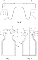
- the figure 1 schematically shows a plug 10, having a lower portion 11, preferably hollow, and an upper portion 12, preferably full.
- This type of cap 10 is fixed in the neck 21 of a container 20 by frictional insertion of said inner portion 11 into said neck 21 of the container 20.
- the Figures 2 and 3 illustrate the insertion of the plug 10 in the neck 21 of a container 20. It is understood, however, that the present invention could also be applied to other types plugs. Similarly, the container could be made differently.
- the outer portion 12 of the cap is intended to cooperate sealingly with an upper radial surface 22 of said neck 21 of the container 20.
- This upper radial surface 22 of the container is generally flat.
- the lower radial surface 13 of said outer portion 12 of the plug 10 which is the surface which cooperates with said upper radial surface 22 of said neck 21 of the container 20 when said plug 10 is in the closed position, may comprise at least one protruding profile 15
- these projecting profiles 15, 16, in the closed position of said plug 10 crash on said upper radial surface 22 of said neck 21 of said container 20, to improve the seal.
- the inner part 11 of the plug 10 comprises a coating 17, such as a film of PTFE (polytetrafluoroethylene), ETFE (ethylene tetrafluoroethylene), ECTFE (ethylene chlorotrifluoroethylene), FEP (fluorinated ethylene propylene) type.
- this coating 17 does not extend to lower radial surface 13 of said outer portion 12 of the plug 10, so that there remains a small uncoated portion on the inner portion 11, which can contribute to the seal when said inner portion 11 is frictionally inserted into said neck 21 of the container 20.
- the upper surface or "plate” of the outer portion 12 of the cap 10 comprises a coating 18 made by a treatment method which uses the atmospheric pressure plasma-assisted polymerization technology. This process uses a "flame" of plasma created at atmospheric pressure, in which a monomer is injected, and which is polymerized on the substrate thus treated.
- a typical plasma processing machine for carrying out the present invention is suitably sized to accommodate the entire plates of plugs as they exit the mold where the rubber is shaped and vulcanized.
- the method of the present invention allows a direct passage from the molding operation to the atmospheric plasma processing operation, without the need for an intermediate treatment.
- the present invention does not involve any washing or surface preparation.
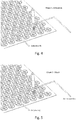
- a surface activation is preferably carried out by passing the plasma flame over the parts to be treated, in particular the plate of uncut plugs from the mold.
- the "canvas” that connects the plugs between them allows to treat only the “plateau” face of the caps, and to hide the coated anti-adherent barrier film face located on the "skirt" part of the caps, which need not be treated by the plasma process.
- different gases can be used to generate the plasma flame: air, argon, nitrogen, helium, oxygen, etc .; the most effective being air or nitrogen, preferably nitrogen, as shown in figure 4 .
- the rate of passage of the plasma flame above the substrate can vary from 10 to 1000 mm / s, preferably from 100 to 500 mm / s, preferably about 300 mm / s, allowing high productivity while ensuring a time sufficient activation treatment of the substrate.
- the number of passes above the substrate to carry out the activation can be from one to five cycles, preferably a single cycle to limit the related costs.
- the activation gas flow rate can vary from 5 to 200 l / min, advantageously from 10 to 100 l / min, preferably about 60 l / min, in order to obtain an effective activation without having too much plasma gas consumption. .
- the distance between the nozzle where the plasma is generated and the substrate may be between 1 and 50 mm, advantageously between 5 and 35 mm, preferably about 20 mm.
- Atmospheric plasma assisted deposition phase Atmospheric plasma assisted deposition phase:
- different gases can be used to generate the plasma flame: air, argon, nitrogen, helium, oxygen, etc .; the most effective being air or nitrogen, preferably air, as illustrated in figure 5 .
- the rate of passage of the plasma flame above the substrate can vary from 10 to 1000 mm / s, preferably from 100 to 500 mm / s, preferably about 300 mm / s, allowing high productivity while ensuring a time sufficient activation treatment of the substrate.
- the number of passes above the substrate for depositing may be from one to five cycles, advantageously from one to three cycles, of preferably two cycles, in order to ensure a complete treatment of the entire area to be treated of the plug plate, remaining in processing times compatible with the industrial requirements.
- the plasma gas flow rate can vary from 5 to 200 l / min, preferably from 10 to 100 l / min, preferably about 60 l / min, in order to obtain an effective activation without having excessive gas consumption.
- the distance between the nozzle where the plasma is generated and the substrate may be between 1 and 50 mm, advantageously between 5 and 35 mm, preferably between 10 and 25 mm.
- the monomers that can be used to deposit are numerous. There may be mentioned saturated or unsaturated hydrocarbons, whether or not containing polar groups (methane, ethane, ethylene, acetylene, benzene, styrene, acrylic acid, pyridine, vinylpyridine, allylamine, etc.), fluorocarbon compounds (tetrafluoromethane, tetrafluoroethylene, hexafluoroacetone, etc.), silicon-based compounds (silanes, siloxanes, silazanes, etc.).
- polar groups methane, ethane, ethylene, acetylene, benzene, styrene, acrylic acid, pyridine, vinylpyridine, allylamine, etc.
- fluorocarbon compounds tetrafluoromethane, tetrafluoroethylene, hexafluoroacetone, etc.
- silicon-based compounds silicon-based compounds
- the development has focused on silicon based compounds, preferably hexamethydisiloxane or hexamethydisilane, the latter having demonstrated an optimal compromise of properties during treatment trials. on a butyl rubber.
- the present invention which in its preferred embodiment combines the production of a plug with a barrier film on the lower part 11 in contact with the drug and the atmospheric plasma coating of the top plate of the plug, thus makes it possible to optimize the performance of the cap, both in the manufacturing phase and in the use phase of the cap.
Description
La présente invention concerne un procédé de traitement d'un élément de conditionnement en élastomère, notamment d'un bouchon destiné à un usage médical ou pharmaceutique, ainsi qu'un élément de conditionnement ainsi traité.The present invention relates to a method of treating an elastomeric packaging element, in particular a plug for a medical or pharmaceutical use, and a packaging element thus treated.
Les éléments de conditionnement en élastomère, tels que les bouchons en caoutchouc, notamment ceux destinés aux récipients de médicaments injectables, présentent le risque de laisser migrer vers le médicament des substances extractibles du caoutchouc : résidus de polymérisation, antioxydants, agents de réticulation, ions issus des charges minérales, etc. La qualité des matières premières disponibles, ainsi que la chimie de vulcanisation des caoutchoucs ne permettent pas de réduire correctement ce niveau de substances extractibles.Elastomeric packaging elements, such as rubber stoppers, especially those intended for injectable drug containers, have the risk of allowing substances extractable from the rubber to migrate to the drug: polymerization residues, antioxidants, crosslinking agents, ions derived from mineral charges, etc. The quality of the raw materials available, as well as the vulcanization chemistry of the rubbers, do not make it possible to reduce this level of extractible substances correctly.
Afin de limiter voire supprimer ce phénomène, une solution consiste à interposer entre la surface du caoutchouc en contact avec l'intérieur du récipient et le médicament un film de polymère inerte, en général un polymère fluoré, de type PTFE (polytétrafluoroéthylène), ETFE (éthylène tétrafluoroéthylène), ECTFE (éthylène chlorotrifluoroéthylène), FEP (éthylène propylène fluoré), etc. Cette solution a en outre l'intérêt de conférer à la partie de bouchon ainsi revêtue de film des propriétés anti-adhérentes et glissantes, permettant au bouchon une insertion aisée dans le col du récipient, ainsi qu'un glissement approprié des bouchons sur les lignes de conditionnement, notamment sur les bols et rails vibrants.In order to limit or even eliminate this phenomenon, one solution consists in interposing between the surface of the rubber in contact with the inside of the container and the drug an inert polymer film, in general a fluorinated polymer, of PTFE (polytetrafluoroethylene), ETFE ( ethylene tetrafluoroethylene), ECTFE (ethylene chlorotrifluoroethylene), FEP (fluorinated ethylene propylene), etc. This solution also has the advantage of giving the film-coated cap part slip and slip properties, allowing the cap easy insertion into the neck of the container, and a proper sliding of the caps on the lines conditioning, especially on bowls and vibrating rails.
En revanche, la partie du bouchon non revêtue de film, notamment la partie supérieure appelée "plateau", n'est pas revêtue de film fluoré anti-adhérent. Cela conduit alors à un risque de collage des pièces entre elles lors du stockage, et un glissement insuffisant lors du convoyage sur les lignes de conditionnement.On the other hand, the portion of the cap not coated with film, in particular the upper part called "plate", is not coated with a non-adhering fluoride film. This then leads to a risk of sticking parts together during storage, and insufficient slip during conveying on the packaging lines.
Il est d'usage de parer à cet inconvénient en enduisant les pièces en caoutchouc d'huile de silicone, soit avec une huile pure, soit avec une émulsion de silicone. Dans ce cas, la totalité de la pièce est in fine recouverte d'une fine couche d'huile de silicone, jouant le rôle de lubrifiant. Cette présence de silicone, notamment sur la partie du bouchon en contact avec le médicament injectable, peut engendrer des problèmes de compatibilité avec certains médicaments, par exemple des protéines.It is customary to overcome this disadvantage by coating the rubber parts with silicone oil, either with a pure oil or with a silicone emulsion. In this case, the entire part is ultimately covered with a thin layer of silicone oil, acting as a lubricant. This presence of silicone, especially on the part of the stopper in contact with the injectable drug, may cause compatibility problems with certain drugs, for example proteins.
Une solution alternative a été de traiter ces bouchons en caoutchouc à film barrière par un dépôt polymérisé d'un monomère injecté dans un plasma froid sous vide. Un procédé de ce type est décrit dans le document
- la réaction a lieu dans une enceinte sous vide, ce qui nécessite une installation spécifique avec un volume utile restreint ainsi que des matériaux et un système de pompage onéreux; de plus la productivité d'un tel procédé est limitée, car il est nécessaire de recréer le vide dans l'enceinte de traitement après chaque déchargement/chargement des pièces à traiter;
- de la même façon qu'avec enduction d'huile de silicone, la totalité de la surface du bouchon va être traitée, ce qui conduit donc à déposer également sur le film barrière un dépôt de polymère anti-adhérent supplémentaire inutile; de plus, étant déposé sur un film de polymère fluoré anti-adhérent, ce second dépôt n'aura pas une accroche suffisante sur le substrat et risque de se décoller du film fluoré, et ainsi créer des particules qui pourront polluer le médicament injectable.
- the reaction takes place in a vacuum chamber, which requires a specific installation with a restricted working volume as well as expensive materials and a pumping system; moreover, the productivity of such a method is limited because it is necessary to recreate the vacuum in the treatment chamber after each unloading / loading of the workpieces;
- in the same way as with silicone oil coating, the entire surface of the plug will be treated, which therefore leads to also depositing on the barrier film a deposit of unnecessary additional non-stick polymer; moreover, being deposited on a fluorinated non-stick polymer film, this second deposit will not have sufficient grip on the substrate and may peel off the fluorinated film, and thus create particles that can pollute the injectable drug.
Une idée par conséquent a été de laisser la partie du bouchon revêtue de film sans autre traitement ou matériau supplémentaire, puisque le polymère remplit les fonctions de barrière et de glissement suffisantes, et de traiter de façon indépendante la partie du bouchon non revêtue de film.An idea, therefore, has been to leave the portion of the film-coated plug without further processing or material, since the polymer performs sufficient barrier and slip functions, and independently processes the portion of the uncoated film plug.
Il était donc souhaitable de mettre en oeuvre une technologie qui :
- laisserait intact le film de polymère fluoré sur la partie du bouchon dirigée vers l'intérieur du récipient; et
- permettrait de traiter sélectivement la partie du bouchon en caoutchouc non revêtue de film fluoré.
- leave the fluoropolymer film intact on the part of the cap directed towards the inside of the container; and
- would selectively treat the portion of the rubber stopper not coated with fluorinated film.
Une solution pour ce faire est décrite dans les documents
- il faut faire appel à des polymères dispersés dans des solvants organiques, qui sont évaporés lors du dépôt; cela constitue un risque environnemental, ainsi qu'un risque sécurité car ces solvants sont inflammables et toxiques; leur gestion est en outre couteuse en énergie (élimination ou recyclage) et en raison des précautions à respecter; une partie de ces solvants est de plus potentiellement adsorbée par le caoutchouc, ce qui peut ensuite engendrer la migration de ces solvants vers le médicament conditionné avec le bouchon;
- il est nécessaire d'utiliser des additifs de type agents de réticulation ou agents d'accrochage sur le substrat caoutchouc; ces produits présentent une certaine toxicité, et présentent également un risque de migration vers le médicament.
- it is necessary to use polymers dispersed in organic solvents, which are evaporated during the deposition; this constitutes an environmental risk, as well as a safety risk because these solvents are flammable and toxic; their management is also expensive in energy (disposal or recycling) and because of the precautions to be respected; some of these solvents are moreover potentially adsorbed by the rubber, which can then cause the migration of these solvents to the drug packaged with the stopper;
- it is necessary to use additives of crosslinking agents or adhesion promoters on the rubber substrate; these products have some toxicity, and also present a risk of migration to the drug.
Les documents
La présente invention a pour but de fournir un procédé de traitement d'un élément de conditionnement en élastomère qui ne reproduit pas les inconvénients susmentionnés.The object of the present invention is to provide a process for treating an elastomeric packaging element which does not reproduce the aforementioned disadvantages.
La présente invention a aussi pour but de fournir un procédé de traitement d'un élément de conditionnement en élastomère qui ne présente aucun risque pour le produit fluide destiné à entrer en contact avec ledit élément de conditionnement.It is another object of the present invention to provide a method of treating an elastomeric packaging member that poses no risk to the fluid product for contacting said conditioning member.
La présente invention a également pour but de fournir un procédé de traitement d'un élément de conditionnement en élastomère qui optimise les performances du bouchon, tant lors de sa fabrication que pendant son utilisation.The present invention also aims to provide a method of treating an elastomeric packaging element which optimizes the performance of the cap, both during its manufacture and during its use.
La présente invention a également pour but de fournir un procédé de traitement d'un élément de conditionnement en élastomère qui est simple et peu coûteux à mettre en oeuvre, et un tel élément de conditionnement qui est simple et peu coûteux à fabriquer et à assembler.The present invention also aims to provide a method of treating an elastomeric packaging element which is simple and inexpensive to implement, and such a packaging element which is simple and inexpensive to manufacture and assemble.
La présente invention a également pour but de fournir un élément de conditionnement en élastomère, notamment d'un bouchon destiné à un usage médical ou pharmaceutique, traité avec le procédé ci-dessus.Another object of the present invention is to provide an elastomeric packaging element, in particular a cap intended for medical or pharmaceutical use, treated with the above process.
La présente a donc pour objet un procédé de traitement d'un élément de conditionnement en élastomère, notamment d'un bouchon destiné à un usage médical ou pharmaceutique, tel que décrit dans la revendication 1 ou la revendication 2. Des modes de réalisation avantageuses sont décrits dans les revendications dépendantes.The subject of the present invention is therefore a process for treating an elastomeric packaging element, in particular a cap intended for a medical or pharmaceutical use, as described in
Ces caractéristiques et avantages et d'autres apparaîtront plus clairement au cours de la description détaillée suivante, faite en référence aux dessins joints, donnés à titre d'exemples non limitatifs, et sur lesquels
- la
figure 1 est une vue schématique d'un exemple de bouchon auquel peut s'appliquer le procédé de traitement de l'invention, - les
figures 2 et 3 sont des vues schématiques du bouchon de lafigure 1 , respectivement avant et après insertion dans le col d'un récipient, et - les
figures 4 et 5 sont des schémas de principe des étapes d'activation et de dépôt d'un procédé de traitement selon un mode de réalisation avantageux de la présente invention.
- the
figure 1 is a schematic view of an example of a plug to which the treatment method of the invention can be applied, - the
Figures 2 and 3 are schematic views of the cap of thefigure 1 , respectively before and after insertion into the neck of a container, and - the
Figures 4 and 5 are schematic diagrams of the activation and deposition steps of a processing method according to an advantageous embodiment of the present invention.
Dans la description, les termes "supérieur" et "inférieur" se réfèrent à la position du bouchon représentée sur les figures, et les termes "axial" et "radial" se réfèrent à l'axe A de la
L'invention s'applique plus particulièrement à des bouchons pharmaceutiques en caoutchouc, mais elle pourrait aussi s'appliquer à d'autres éléments de conditionnements dans le domaine médical ou pharmaceutique.The invention is more particularly applicable to pharmaceutical rubber stoppers, but it could also be applied to other packaging elements in the medical or pharmaceutical field.
La
La partie externe 12 du bouchon est destinée à coopérer de manière étanche avec une surface radiale supérieure 22 dudit col 21 du récipient 20. Cette surface radiale supérieure 22 du récipient est généralement plane.The
La surface radiale inférieure 13 de ladite partie externe 12 du bouchon 10, qui est la surface qui coopère avec ladite surface radiale supérieure 22 dudit col 21 du récipient 20 lorsque ledit bouchon 10 est en position de fermeture, peut comporter au moins un profil saillant 15, 16. Avantageusement, ces profils saillants 15, 16, en position de fermeture dudit bouchon 10, s'écrasent sur ladite surface radiale supérieure 22 dudit col 21 dudit récipient 20, pour améliorer l'étanchéité.The lower
Avantageusement, la partie interne 11 du bouchon 10 comporte un revêtement 17, tel qu'un film de type PTFE (polytétrafluoroéthylène), ETFE (éthylène tétrafluoroéthylène), ECTFE (éthylène chlorotrifluoroéthylène), FEP (éthylène propylène fluoré). Eventuellement, comme visible sur la
Selon l'invention, la surface supérieure ou "plateau" de la partie externe 12 du bouchon 10 comporte un revêtement 18 réalisé par un procédé de traitement qui utilise la technologie de polymérisation assistée par plasma à pression atmosphérique. Ce procédé utilise une "flamme" de plasma créée à pression atmosphérique, dans laquelle un monomère est injecté, et qui vient se polymériser sur le substrat ainsi traité.According to the invention, the upper surface or "plate" of the
Une machine de traitement plasma typique pour mettre en oeuvre la présente invention est avantageusement de taille adaptée pour accueillir les plaques entières de bouchons telles qu'elles sortent du moule où le caoutchouc est mis en forme et vulcanisé.A typical plasma processing machine for carrying out the present invention is suitably sized to accommodate the entire plates of plugs as they exit the mold where the rubber is shaped and vulcanized.
Le procédé de la présente invention permet un passage direct de l'opération de moulage à l'opération de traitement par plasma atmosphérique, sans qu'il n'y ait de besoin d'un traitement intermédiaire. En particulier, la présente invention n'implique aucun lavage, ni préparation de surface.The method of the present invention allows a direct passage from the molding operation to the atmospheric plasma processing operation, without the need for an intermediate treatment. In particular, the present invention does not involve any washing or surface preparation.
Le procédé de l'invention, selon un mode de réalisation avantageux de celle-ci, comporte deux étapes:
- une phase d'activation de surface assistée par plasma atmosphérique; et
- une phase de dépôt assisté par plasma atmosphérique.
- a surface activation phase assisted by atmospheric plasma; and
- an atmospheric plasma assisted deposition phase.
Les
Afin de favoriser une adhésion future efficace du dépôt, une activation de surface est de préférence réalisée en passant la flamme de plasma au-dessus des pièces à traiter, en particulier la plaque de bouchons non découpés issue du moule. La "toile" qui relie les bouchons entre eux permet de ne traiter que la face "plateau" des bouchons, et de masquer la face revêtue de film barrière anti adhérent situé sur la partie "jupe" des bouchons, qui n'a pas besoin d'être traitée par le procédé plasma.In order to promote an effective future adhesion of the deposit, a surface activation is preferably carried out by passing the plasma flame over the parts to be treated, in particular the plate of uncut plugs from the mold. The "canvas" that connects the plugs between them allows to treat only the "plateau" face of the caps, and to hide the coated anti-adherent barrier film face located on the "skirt" part of the caps, which need not be treated by the plasma process.
Pour activer la surface, différents gaz peuvent être utilisés pour générer la flamme de plasma : air, argon, azote, hélium, oxygène, etc.; les plus efficaces étant l'air ou l'azote, de préférence l'azote, comme illustré sur la
La vitesse de passage de la flamme de plasma au-dessus du substrat peut varier de 10 à 1000 mm/s, avantageusement de 100 à 500 mm/s, de préférence environ 300 mm/s, permettant une productivité élevée tout en assurant un temps de traitement d'activation suffisant du substrat.The rate of passage of the plasma flame above the substrate can vary from 10 to 1000 mm / s, preferably from 100 to 500 mm / s, preferably about 300 mm / s, allowing high productivity while ensuring a time sufficient activation treatment of the substrate.
Le nombre de passages au-dessus du substrat pour réaliser l'activation peut être de un à cinq cycles, avantageusement un seul cycle afin de limiter les couts afférents.The number of passes above the substrate to carry out the activation can be from one to five cycles, preferably a single cycle to limit the related costs.
Le débit de gaz d'activation peut varier de 5 à 200 l/min, avantageusement de 10 à 100 l/min, de préférence environ 60 l/min, afin d'obtenir une activation efficace sans avoir une consommation trop importante de gaz plasmagène.The activation gas flow rate can vary from 5 to 200 l / min, advantageously from 10 to 100 l / min, preferably about 60 l / min, in order to obtain an effective activation without having too much plasma gas consumption. .
La distance entre la buse où est généré le plasma et le substrat peut être comprise entre 1 et 50 mm, avantageusement entre 5 et 35 mm, de préférence environ 20 mm.The distance between the nozzle where the plasma is generated and the substrate may be between 1 and 50 mm, advantageously between 5 and 35 mm, preferably about 20 mm.
Pour obtenir une polymérisation efficace du monomère avec ce procédé, différents gaz peuvent être utilisés pour générer la flamme de plasma : air, argon, azote, hélium, oxygène, etc.; les plus efficaces étant l'air ou l'azote, de préférence l'air, comme illustré sur la
La vitesse de passage de la flamme de plasma au-dessus du substrat peut varier de 10 à 1000 mm/s, avantageusement de 100 à 500 mm/s, de préférence environ 300 mm/s, permettant une productivité élevée tout en assurant un temps de traitement d'activation suffisant du substrat.The rate of passage of the plasma flame above the substrate can vary from 10 to 1000 mm / s, preferably from 100 to 500 mm / s, preferably about 300 mm / s, allowing high productivity while ensuring a time sufficient activation treatment of the substrate.
Le nombre de passages au-dessus du substrat pour réaliser le dépôt peut être de un à cinq cycles, avantageusement de un à trois cycles, de préférence deux cycles, afin d'assurer un traitement complet de toute la zone à traiter de la plaque de bouchons, en restant dans des temps de traitement compatibles avec les exigences industrielles.The number of passes above the substrate for depositing may be from one to five cycles, advantageously from one to three cycles, of preferably two cycles, in order to ensure a complete treatment of the entire area to be treated of the plug plate, remaining in processing times compatible with the industrial requirements.
Le débit de gaz plasmagène peut varier de 5 à 200 l/min, avantageusement de 10 à 100 l/min, de préférence environ 60 l/min, afin d'obtenir une activation efficace sans avoir une consommation trop importante de gaz.The plasma gas flow rate can vary from 5 to 200 l / min, preferably from 10 to 100 l / min, preferably about 60 l / min, in order to obtain an effective activation without having excessive gas consumption.
La distance entre la buse où est généré le plasma et le substrat peut être comprise entre 1 et 50 mm, avantageusement entre 5 et 35 mm, de préférence entre 10 et 25 mm.The distance between the nozzle where the plasma is generated and the substrate may be between 1 and 50 mm, advantageously between 5 and 35 mm, preferably between 10 and 25 mm.
Les monomères utilisables pour réaliser le dépôt sont multiples. On peut notamment citer les hydrocarbures saturés ou non, contenant ou non des groupements polaires (méthane, éthane, éthylène, acétylène, benzène, styrène, acide acrylique, pyridine, vinylpyridine, allylamine, etc.), les composés fluorocarbonés (tétrafluorométhane, tétrafluoroéthylène, hexafluoroacétone, etc.), les composés à base de silicium (silanes, siloxanes, silazanes, etc.).The monomers that can be used to deposit are numerous. There may be mentioned saturated or unsaturated hydrocarbons, whether or not containing polar groups (methane, ethane, ethylene, acetylene, benzene, styrene, acrylic acid, pyridine, vinylpyridine, allylamine, etc.), fluorocarbon compounds (tetrafluoromethane, tetrafluoroethylene, hexafluoroacetone, etc.), silicon-based compounds (silanes, siloxanes, silazanes, etc.).
Dans un mode de réalisation particulier de la présente invention, le développement s'est concentré sur les composés à base de silicium, de préférence l'hexaméthydisiloxane ou l'hexaméthydisilane, ce dernier ayant démontré un compromis de propriétés optimal lors d'essais de traitement sur un caoutchouc butyle.In a particular embodiment of the present invention, the development has focused on silicon based compounds, preferably hexamethydisiloxane or hexamethydisilane, the latter having demonstrated an optimal compromise of properties during treatment trials. on a butyl rubber.
La technologie de la présente invention a de nombreux avantages :
- elle n'utilise que des gaz inertes, en quantité raisonnable, et une faible quantité de monomère (siloxanique en général), donc ne présentant aucun risque envers l'environnement;
- elle crée un dépôt polymérisé ne contenant aucun composé toxique, ni solvant résiduel;
- elle permet de traiter sélectivement la face
supérieure ou plateau 18 du bouchon en caoutchouc, sans interférer sur la partie inférieure déjà avantageusement revêtue d'un film de polymère fluoré; - elle permet de créer une
surface 18 anti-adhérente et glissante sur le plateau du bouchon, permettant l'absence de collage des pièces entre elles, et un glissement aisé des pièces sur les lignes de conditionnement; - elle permet de traiter des surfaces de caoutchouc très importantes en quelques secondes, donc une capacité de production intéressante;
- elle ne nécessite pas d'enceinte de travail sous vide, ce qui permet de limiter les coûts de machine, et garantit une excellente productivité, car on supprime les temps de mise sous vide de l'enceinte de travail par rapport à un procédé de plasma sous vide.
- it only uses inert gases, in a reasonable quantity, and a small amount of monomer (siloxane in general), and therefore poses no risk to the environment;
- it creates a polymerized deposit containing no toxic compound or residual solvent;
- it makes it possible to selectively treat the upper face or
plate 18 of the rubber stopper, without interfering with the lower part which is already advantageously coated with a fluoropolymer film; - it makes it possible to create a non-adhering and
slippery surface 18 on the cap plate, allowing the absence of bonding of the parts together, and easy sliding of the parts on the packaging lines; - it allows to treat very important rubber surfaces in a few seconds, so an interesting production capacity;
- it does not require a vacuum working enclosure, which makes it possible to limit the machine costs, and guarantees excellent productivity, since the evacuation times of the working chamber are suppressed with respect to a plasma process under vacuum.
Les bouchons 10 obtenus avec le procédé préférentiel de l'invention combinent donc les avantages suivants :
- élasticité du caoutchouc permettant une obturation performante du col de récipient;
- protection envers les gaz (oxygène, humidité) par la faible perméabilité du caoutchouc utilisé;
- absence ou très faible niveau de migration de substances du caoutchouc vers le médicament en raison de l'effet barrière du polymère fluoré;
- absence d'huile de silicone sur le bouchon;
- absence de collage des pièces sur la partie supérieure ou plateau en raison du traitement polymérisé appliqué par la technologie de plasma atmosphérique.
- elasticity of the rubber allowing a high performance closure of the container neck;
- protection against gases (oxygen, moisture) by the low permeability of the rubber used;
- absence or very low level of migration of substances from the rubber to the drug due to the barrier effect of the fluoropolymer;
- lack of silicone oil on the cap;
- no sticking of parts on the upper part or plate because of the polymerized treatment applied by atmospheric plasma technology.
La présente invention, qui dans son mode de réalisation préféré combine la réalisation d'un bouchon avec un film barrière sur la partie inférieure 11 en contact avec le médicament et le revêtement par plasma atmosphérique du plateau supérieur du bouchon, permet donc d'optimiser les performances du bouchon, aussi bien en phase de fabrication qu'en phase d'utilisation du bouchon.The present invention, which in its preferred embodiment combines the production of a plug with a barrier film on the
Claims (5)
- A method of treating an elastomer packaging element (10), in particular a stopper for medical or pharmaceutical use, said packaging element (10) having a bottom portion (11) that is to penetrate into a neck (21) of a container (20) and a top portion (12) that is to co-operate in sealed manner with a top surface (22) of said neck (21) of the container (20), the top surface of said top portion (12) being treated by a plasma-assisted polymerization method at atmospheric pressure using a plasma flame created at atmospheric pressure and into which a monomer is injected, said monomer polymerizing on said top surface in order to form a coating (18), said method comprising a stage of atmospheric plasma-assisted surface activation and a stage of atmospheric plasma-assisted deposition, the method being characterized in that said atmospheric plasma-assisted surface activation stage comprises passing said plasma flame over said top surface, with the following parameters:- gas used for generating the plasma flame: air, argon, nitrogen, helium, oxygen, advantageously air or nitrogen; preferably nitrogen;- speed at which the plasma flame passes over said top surface: 10 mm/s to 1000 mm/s, and advantageously 100 mm/s to 500 mm/s, preferably 300 mm/s;- number of passes over said top surface to perform activation: one cycle to five cycles, advantageously a single cycle;- activation gas flow rate: 5 L/min to 200 L/min, and advantageously 10 L/min to 100 L/min, preferably 60 L/min;- distance between the nozzle where the plasma is generated and said top surface: in the range 1 mm to 50 mm, and advantageously in the range 5 mm to 35 mm, preferably 20 mm.
- A method of treating an elastomer packaging element (10), in particular a stopper for medical or pharmaceutical use, said packaging element (10) having a bottom portion (11) that is to penetrate into a neck (21) of a container (20) and a top portion (12) that is to co-operate in sealed manner with a top surface (22) of said neck (21) of the container (20), the top surface of said top portion (12) being treated by a plasma-assisted polymerization method at atmospheric pressure using a plasma flame created at atmospheric pressure and into which a monomer is injected, said monomer polymerizing on said top surface in order to form a coating (18), said method comprising a stage of atmospheric plasma-assisted surface activation and a stage of atmospheric plasma-assisted deposition, the method being characterized in that said atmospheric plasma-assisted deposition stage comprises passing said plasma flame over said top surface with the following parameters:- gas used for generating the plasma flame: air, argon, nitrogen, helium, oxygen, etc.; advantageously air or nitrogen; preferably air;- speed at which the plasma flame is passed over said top surface: 10 mm/s to 1000 mm/s, and advantageously 100 mm/s to 500 mm/s, preferably 300 mm/s;- number of passes over said top surface to perform activation: one cycle to five cycles, and advantageously one cycle to three cycles, preferably two cycles;- activation gas flow rate: 5 L/min to 200 L/min, and advantageously 10 L/min to 100 L/min, preferably 60 L/min;- distance between the nozzle where the plasma is generated and said top surface: in the range 1 mm to 50 mm, and advantageously in the range 5 mm to 35 mm, preferably in the range 10 mm to 25 mm.
- A method according to claim 1, wherein said atmospheric plasma-assisted deposition stage comprises passing said plasma flame over said top surface with the following parameters:- gas used for generating the plasma flame: air, argon, nitrogen, helium, oxygen, advantageously air or nitrogen; preferably air;- speed at which the plasma flame is passed over said top surface: 10 mm/s to 1000 mm/s, and advantageously 100 mm/s to 500 mm/s, preferably 300 mm/s;- number of passes over said top surface to perform activation: one cycle to five cycles, and advantageously one cycle to three cycles, preferably two cycles;- activation gas flow rate: 5 L/min to 200 L/min, and advantageously 10 L/min to 100 L/min, preferably 60 L/min;- distance between the nozzle where the plasma is generated and said top surface: in the range 1 mm to 50 mm, and advantageously in the range 5 mm to 35 mm, preferably in the range 10 mm to 25 mm.
- A method according to any preceding claim, wherein said monomer is selected from optionally-saturated hydrocarbons optionally containing polar groups such as methane, ethane, ethylene, acetylene, benzene, styrene, acrylic acid, pyridine, vinylpyridine, and allylamine, fluorocarbon compounds such as tetrafluoromethane, tetrafluoroethylene, and hexafluoroacetone, and silicon-based compounds such as silanes, siloxanes, and silazanes.
- A method according to any preceding claim, wherein said internal portion (11) of said packaging (10) has a coating (17) such as a film of PTFE (polytetrafluoroethylene), ETFE (ethylene tetrafluoroethylene), ECTFE (ethylene chlorotrifluoroethylene), or FEP (fluorinated ethylene propylene) type.
Priority Applications (1)
| Application Number | Priority Date | Filing Date | Title |
|---|---|---|---|
| PL16819592T PL3374419T3 (en) | 2015-11-12 | 2016-11-09 | Method for treating an elastomer packaging element, and packaging element thus treated |
Applications Claiming Priority (2)
| Application Number | Priority Date | Filing Date | Title |
|---|---|---|---|
| FR1560792A FR3043679B1 (en) | 2015-11-12 | 2015-11-12 | PROCESS FOR TREATING AN ELASTOMERIC PACKAGING ELEMENT, AND PACKAGING ELEMENT THUS TREATED. |
| PCT/FR2016/052910 WO2017081409A1 (en) | 2015-11-12 | 2016-11-09 | Method for treating an elastomer packaging element, and packaging element thus treated |
Publications (2)
| Publication Number | Publication Date |
|---|---|
| EP3374419A1 EP3374419A1 (en) | 2018-09-19 |
| EP3374419B1 true EP3374419B1 (en) | 2019-10-09 |
Family
ID=55411500
Family Applications (1)
| Application Number | Title | Priority Date | Filing Date |
|---|---|---|---|
| EP16819592.3A Active EP3374419B1 (en) | 2015-11-12 | 2016-11-09 | Method for treating an elastomer packaging element, and packaging element thus treated |
Country Status (11)
| Country | Link |
|---|---|
| US (1) | US10995190B2 (en) |
| EP (1) | EP3374419B1 (en) |
| JP (1) | JP6914255B2 (en) |
| KR (1) | KR20180084084A (en) |
| CN (1) | CN108350205B (en) |
| DK (1) | DK3374419T3 (en) |
| FR (1) | FR3043679B1 (en) |
| IL (1) | IL258939B (en) |
| PL (1) | PL3374419T3 (en) |
| TW (1) | TWI596232B (en) |
| WO (1) | WO2017081409A1 (en) |
Families Citing this family (3)
| Publication number | Priority date | Publication date | Assignee | Title |
|---|---|---|---|---|
| JP2019107445A (en) * | 2017-12-15 | 2019-07-04 | ニプロ株式会社 | Medical glass container and production method thereof |
| WO2019117267A1 (en) * | 2017-12-15 | 2019-06-20 | ニプロ株式会社 | Medical glass container and method for manufacturing same |
| FR3092568B1 (en) * | 2019-02-08 | 2021-04-16 | Sartorius Stedim Fmt Sas | Hermetic cap for mouthpiece |
Family Cites Families (24)
| Publication number | Priority date | Publication date | Assignee | Title |
|---|---|---|---|---|
| JPS5650930A (en) * | 1979-10-02 | 1981-05-08 | Asahi Glass Co Ltd | Rubber stopper for sealing |
| FR2549869B1 (en) * | 1983-07-29 | 1986-07-11 | Electricite De France | METHOD AND DEVICE FOR PERFORMING IN SITU POLYMERIZATION OF FLUOCARBON MONOMERS ON A SUBSTRATE |
| US5114794A (en) | 1987-06-23 | 1992-05-19 | Daikyo Gomu Seiko Ltd. | Modified polysiloxane-coated sanitary rubber article and a process for the production of the same |
| JP3100727B2 (en) | 1992-01-23 | 2000-10-23 | 株式会社大協精工 | Modified polysiloxane composition and sanitary rubber product coated with the composition |
| US5362680A (en) * | 1992-08-18 | 1994-11-08 | Texas Instruments Incorporated | Technique for enhancing adhesion capability of heat spreaders in molded packages |
| FR2733758B1 (en) * | 1995-05-04 | 1997-07-18 | Stelumi Sa | PROCESS AND TREATMENT OF A PACKAGING ELEMENT, ESPECIALLY FOR MEDICAL OR PHARMACEUTICAL USE; CONDITIONING ELEMENT THUS PROCESSED |
| TW333462B (en) * | 1996-04-23 | 1998-06-11 | Pharmacia & Upjohn Ab | Improved medical containers |
| DE19754056C1 (en) * | 1997-12-05 | 1999-04-08 | Schott Glas | Production of coated elastomer components for medical use |
| DE10011276A1 (en) * | 2000-03-08 | 2001-09-13 | Wolff Walsrode Ag | Process employing indirect atmospheric plasmatron, surface-treats or coats thin metallic foil or polymer sheet |
| DE10011274A1 (en) * | 2000-03-08 | 2001-09-13 | Wolff Walsrode Ag | Plasma-treated sheet materials |
| WO2002100928A1 (en) * | 2001-06-12 | 2002-12-19 | North Carolina State University | Barrier coatings for elastomeric materials |
| US6793759B2 (en) * | 2001-10-09 | 2004-09-21 | Dow Corning Corporation | Method for creating adhesion during fabrication of electronic devices |
| US20080213496A1 (en) * | 2002-02-14 | 2008-09-04 | Applied Materials, Inc. | Method of coating semiconductor processing apparatus with protective yttrium-containing coatings |
| US20050158472A1 (en) * | 2002-02-18 | 2005-07-21 | Joachim Karthauser | Methods of treating polymeric subtrates |
| US8236382B2 (en) * | 2002-09-30 | 2012-08-07 | Lam Research Corporation | Proximity substrate preparation sequence, and method, apparatus, and system for implementing the same |
| JP2007501110A (en) * | 2003-08-04 | 2007-01-25 | チバ スペシャルティ ケミカルズ ホールディング インコーポレーテッド | Method for producing a strongly adherent coating |
| EP1658391A2 (en) * | 2003-08-04 | 2006-05-24 | Ciba SC Holding AG | Process for the production of strongly adherent coatings |
| US20050112292A1 (en) * | 2003-11-25 | 2005-05-26 | Parker Russell A. | Methods for treating at least one member of a microarray structure and methods of using the same |
| SE0402197D0 (en) * | 2004-09-10 | 2004-09-10 | Tetra Laval Holdings & Finance | A polymer film, a packaging laminate comprising the polymer film, a packaging container formed from the packaging laminate and a process for the production of the polymer film |
| US7517561B2 (en) * | 2005-09-21 | 2009-04-14 | Ford Global Technologies, Llc | Method of coating a substrate for adhesive bonding |
| DE102006018491A1 (en) * | 2006-04-19 | 2007-10-25 | Fraunhofer-Gesellschaft zur Förderung der angewandten Forschung e.V. | Flexible plasma polymer products, corresponding articles, manufacturing methods and use |
| EP2052097B1 (en) * | 2006-07-31 | 2016-12-07 | Tekna Plasma Systems, Inc. | Plasma surface treatment using dielectric barrier discharges |
| US20110014395A1 (en) * | 2007-09-06 | 2011-01-20 | Universite Libre De Bruxelles | Method for depositing a fluorinated layer from a precursor monomer |
| US10751752B2 (en) * | 2016-10-13 | 2020-08-25 | Permasteelisa North America Corp. | Method of increasing surface adhesion of an architectural metal finish |
-
2015
- 2015-11-12 FR FR1560792A patent/FR3043679B1/en active Active
-
2016
- 2016-11-09 JP JP2018524409A patent/JP6914255B2/en active Active
- 2016-11-09 CN CN201680065677.0A patent/CN108350205B/en active Active
- 2016-11-09 KR KR1020187016516A patent/KR20180084084A/en not_active Application Discontinuation
- 2016-11-09 WO PCT/FR2016/052910 patent/WO2017081409A1/en active Application Filing
- 2016-11-09 DK DK16819592.3T patent/DK3374419T3/en active
- 2016-11-09 US US15/772,309 patent/US10995190B2/en active Active
- 2016-11-09 EP EP16819592.3A patent/EP3374419B1/en active Active
- 2016-11-09 PL PL16819592T patent/PL3374419T3/en unknown
- 2016-11-11 TW TW105136963A patent/TWI596232B/en not_active IP Right Cessation
-
2018
- 2018-04-25 IL IL258939A patent/IL258939B/en active IP Right Grant
Non-Patent Citations (1)
| Title |
|---|
| None * |
Also Published As
| Publication number | Publication date |
|---|---|
| WO2017081409A1 (en) | 2017-05-18 |
| CN108350205B (en) | 2024-04-09 |
| TWI596232B (en) | 2017-08-21 |
| EP3374419A1 (en) | 2018-09-19 |
| KR20180084084A (en) | 2018-07-24 |
| FR3043679B1 (en) | 2021-07-23 |
| US10995190B2 (en) | 2021-05-04 |
| PL3374419T3 (en) | 2020-04-30 |
| TW201716623A (en) | 2017-05-16 |
| JP6914255B2 (en) | 2021-08-04 |
| IL258939A (en) | 2018-06-28 |
| CN108350205A (en) | 2018-07-31 |
| FR3043679A1 (en) | 2017-05-19 |
| IL258939B (en) | 2021-04-29 |
| US20180319946A1 (en) | 2018-11-08 |
| DK3374419T3 (en) | 2020-01-13 |
| JP2018536738A (en) | 2018-12-13 |
Similar Documents
| Publication | Publication Date | Title |
|---|---|---|
| EP3374419B1 (en) | Method for treating an elastomer packaging element, and packaging element thus treated | |
| EP0823933B1 (en) | Method for treating a packaging element, particularly for medical or pharmaceutical use, and packaging element treated thereby | |
| EP3250269B1 (en) | Syringe plunger-stopper | |
| EP0693434B1 (en) | Screw cap with liner | |
| US20050158472A1 (en) | Methods of treating polymeric subtrates | |
| EP3055006A1 (en) | Sliding plunger-plug and syringe device comprising such a plunger-plug | |
| EP2131965A2 (en) | Thin film coating method | |
| EP0678547B1 (en) | Process for the surface treatment of articles comprising at least one plastic component | |
| EP1440020B1 (en) | Valve seal | |
| WO2005003251A2 (en) | Valve seal and device for dispensing a fluid product while being provided with a seal of this type | |
| JP6924371B2 (en) | Gasket for syringe and syringe using the gasket | |
| WO2021240109A1 (en) | Anti-ozonant composition for a crosslinked rubber article | |
| FR2769678A1 (en) | Seal for pump or valve in spray containers has matrix with barrier coating to prevent contamination of propellant solution | |
| WO2020053508A1 (en) | Valve seal and metering valve for fluid product dispenser | |
| FR2769679A1 (en) | Valve or pump seal | |
| FR3032122A1 (en) | PROCESS FOR PRODUCING A SYRINGE PISTON PLUG | |
| WO2020170116A1 (en) | Method for preparing a syringe | |
| WO2013038119A2 (en) | Device for storing and dispensing liquid | |
| FR2749013A1 (en) | MOLDED PART OF IODINE TREATED MATERIAL AND METHOD OF MANUFACTURING SUCH MATERIAL | |
| FR2861700A1 (en) | Stoppers of foamed, crosslinked polyolefin-based plastics composition, useful e.g. for wine or champagne bottles |
Legal Events
| Date | Code | Title | Description |
|---|---|---|---|
| STAA | Information on the status of an ep patent application or granted ep patent |
Free format text: STATUS: UNKNOWN |
|
| STAA | Information on the status of an ep patent application or granted ep patent |
Free format text: STATUS: THE INTERNATIONAL PUBLICATION HAS BEEN MADE |
|
| PUAI | Public reference made under article 153(3) epc to a published international application that has entered the european phase |
Free format text: ORIGINAL CODE: 0009012 |
|
| STAA | Information on the status of an ep patent application or granted ep patent |
Free format text: STATUS: REQUEST FOR EXAMINATION WAS MADE |
|
| 17P | Request for examination filed |
Effective date: 20180608 |
|
| AK | Designated contracting states |
Kind code of ref document: A1 Designated state(s): AL AT BE BG CH CY CZ DE DK EE ES FI FR GB GR HR HU IE IS IT LI LT LU LV MC MK MT NL NO PL PT RO RS SE SI SK SM TR |
|
| AX | Request for extension of the european patent |
Extension state: BA ME |
|
| DAV | Request for validation of the european patent (deleted) | ||
| DAX | Request for extension of the european patent (deleted) | ||
| STAA | Information on the status of an ep patent application or granted ep patent |
Free format text: STATUS: EXAMINATION IS IN PROGRESS |
|
| 17Q | First examination report despatched |
Effective date: 20190307 |
|
| GRAP | Despatch of communication of intention to grant a patent |
Free format text: ORIGINAL CODE: EPIDOSNIGR1 |
|
| STAA | Information on the status of an ep patent application or granted ep patent |
Free format text: STATUS: GRANT OF PATENT IS INTENDED |
|
| INTG | Intention to grant announced |
Effective date: 20190503 |
|
| GRAS | Grant fee paid |
Free format text: ORIGINAL CODE: EPIDOSNIGR3 |
|
| GRAA | (expected) grant |
Free format text: ORIGINAL CODE: 0009210 |
|
| STAA | Information on the status of an ep patent application or granted ep patent |
Free format text: STATUS: THE PATENT HAS BEEN GRANTED |
|
| AK | Designated contracting states |
Kind code of ref document: B1 Designated state(s): AL AT BE BG CH CY CZ DE DK EE ES FI FR GB GR HR HU IE IS IT LI LT LU LV MC MK MT NL NO PL PT RO RS SE SI SK SM TR |
|
| REG | Reference to a national code |
Ref country code: GB Ref legal event code: FG4D Free format text: NOT ENGLISH |
|
| REG | Reference to a national code |
Ref country code: CH Ref legal event code: EP |
|
| REG | Reference to a national code |
Ref country code: DE Ref legal event code: R096 Ref document number: 602016022301 Country of ref document: DE |
|
| REG | Reference to a national code |
Ref country code: IE Ref legal event code: FG4D Free format text: LANGUAGE OF EP DOCUMENT: FRENCH |
|
| REG | Reference to a national code |
Ref country code: AT Ref legal event code: REF Ref document number: 1188736 Country of ref document: AT Kind code of ref document: T Effective date: 20191115 |
|
| REG | Reference to a national code |
Ref country code: CH Ref legal event code: NV Representative=s name: BOVARD AG PATENT- UND MARKENANWAELTE, CH |
|
| REG | Reference to a national code |
Ref country code: DK Ref legal event code: T3 Effective date: 20200108 |
|
| REG | Reference to a national code |
Ref country code: NL Ref legal event code: FP |
|
| REG | Reference to a national code |
Ref country code: SE Ref legal event code: TRGR |
|
| REG | Reference to a national code |
Ref country code: LT Ref legal event code: MG4D |
|
| PG25 | Lapsed in a contracting state [announced via postgrant information from national office to epo] |
Ref country code: LT Free format text: LAPSE BECAUSE OF FAILURE TO SUBMIT A TRANSLATION OF THE DESCRIPTION OR TO PAY THE FEE WITHIN THE PRESCRIBED TIME-LIMIT Effective date: 20191009 Ref country code: BG Free format text: LAPSE BECAUSE OF FAILURE TO SUBMIT A TRANSLATION OF THE DESCRIPTION OR TO PAY THE FEE WITHIN THE PRESCRIBED TIME-LIMIT Effective date: 20200109 Ref country code: FI Free format text: LAPSE BECAUSE OF FAILURE TO SUBMIT A TRANSLATION OF THE DESCRIPTION OR TO PAY THE FEE WITHIN THE PRESCRIBED TIME-LIMIT Effective date: 20191009 Ref country code: NO Free format text: LAPSE BECAUSE OF FAILURE TO SUBMIT A TRANSLATION OF THE DESCRIPTION OR TO PAY THE FEE WITHIN THE PRESCRIBED TIME-LIMIT Effective date: 20200109 Ref country code: LV Free format text: LAPSE BECAUSE OF FAILURE TO SUBMIT A TRANSLATION OF THE DESCRIPTION OR TO PAY THE FEE WITHIN THE PRESCRIBED TIME-LIMIT Effective date: 20191009 Ref country code: GR Free format text: LAPSE BECAUSE OF FAILURE TO SUBMIT A TRANSLATION OF THE DESCRIPTION OR TO PAY THE FEE WITHIN THE PRESCRIBED TIME-LIMIT Effective date: 20200110 Ref country code: ES Free format text: LAPSE BECAUSE OF FAILURE TO SUBMIT A TRANSLATION OF THE DESCRIPTION OR TO PAY THE FEE WITHIN THE PRESCRIBED TIME-LIMIT Effective date: 20191009 Ref country code: PT Free format text: LAPSE BECAUSE OF FAILURE TO SUBMIT A TRANSLATION OF THE DESCRIPTION OR TO PAY THE FEE WITHIN THE PRESCRIBED TIME-LIMIT Effective date: 20200210 |
|
| PG25 | Lapsed in a contracting state [announced via postgrant information from national office to epo] |
Ref country code: HR Free format text: LAPSE BECAUSE OF FAILURE TO SUBMIT A TRANSLATION OF THE DESCRIPTION OR TO PAY THE FEE WITHIN THE PRESCRIBED TIME-LIMIT Effective date: 20191009 Ref country code: IS Free format text: LAPSE BECAUSE OF FAILURE TO SUBMIT A TRANSLATION OF THE DESCRIPTION OR TO PAY THE FEE WITHIN THE PRESCRIBED TIME-LIMIT Effective date: 20200224 Ref country code: RS Free format text: LAPSE BECAUSE OF FAILURE TO SUBMIT A TRANSLATION OF THE DESCRIPTION OR TO PAY THE FEE WITHIN THE PRESCRIBED TIME-LIMIT Effective date: 20191009 |
|
| PG25 | Lapsed in a contracting state [announced via postgrant information from national office to epo] |
Ref country code: AL Free format text: LAPSE BECAUSE OF FAILURE TO SUBMIT A TRANSLATION OF THE DESCRIPTION OR TO PAY THE FEE WITHIN THE PRESCRIBED TIME-LIMIT Effective date: 20191009 |
|
| REG | Reference to a national code |
Ref country code: DE Ref legal event code: R097 Ref document number: 602016022301 Country of ref document: DE |
|
| PG2D | Information on lapse in contracting state deleted |
Ref country code: IS |
|
| PG25 | Lapsed in a contracting state [announced via postgrant information from national office to epo] |
Ref country code: RO Free format text: LAPSE BECAUSE OF FAILURE TO SUBMIT A TRANSLATION OF THE DESCRIPTION OR TO PAY THE FEE WITHIN THE PRESCRIBED TIME-LIMIT Effective date: 20191009 Ref country code: CZ Free format text: LAPSE BECAUSE OF FAILURE TO SUBMIT A TRANSLATION OF THE DESCRIPTION OR TO PAY THE FEE WITHIN THE PRESCRIBED TIME-LIMIT Effective date: 20191009 Ref country code: EE Free format text: LAPSE BECAUSE OF FAILURE TO SUBMIT A TRANSLATION OF THE DESCRIPTION OR TO PAY THE FEE WITHIN THE PRESCRIBED TIME-LIMIT Effective date: 20191009 Ref country code: MC Free format text: LAPSE BECAUSE OF FAILURE TO SUBMIT A TRANSLATION OF THE DESCRIPTION OR TO PAY THE FEE WITHIN THE PRESCRIBED TIME-LIMIT Effective date: 20191009 Ref country code: IS Free format text: LAPSE BECAUSE OF FAILURE TO SUBMIT A TRANSLATION OF THE DESCRIPTION OR TO PAY THE FEE WITHIN THE PRESCRIBED TIME-LIMIT Effective date: 20200209 |
|
| PLBE | No opposition filed within time limit |
Free format text: ORIGINAL CODE: 0009261 |
|
| STAA | Information on the status of an ep patent application or granted ep patent |
Free format text: STATUS: NO OPPOSITION FILED WITHIN TIME LIMIT |
|
| PG25 | Lapsed in a contracting state [announced via postgrant information from national office to epo] |
Ref country code: SM Free format text: LAPSE BECAUSE OF FAILURE TO SUBMIT A TRANSLATION OF THE DESCRIPTION OR TO PAY THE FEE WITHIN THE PRESCRIBED TIME-LIMIT Effective date: 20191009 Ref country code: SK Free format text: LAPSE BECAUSE OF FAILURE TO SUBMIT A TRANSLATION OF THE DESCRIPTION OR TO PAY THE FEE WITHIN THE PRESCRIBED TIME-LIMIT Effective date: 20191009 |
|
| 26N | No opposition filed |
Effective date: 20200710 |
|
| PG25 | Lapsed in a contracting state [announced via postgrant information from national office to epo] |
Ref country code: SI Free format text: LAPSE BECAUSE OF FAILURE TO SUBMIT A TRANSLATION OF THE DESCRIPTION OR TO PAY THE FEE WITHIN THE PRESCRIBED TIME-LIMIT Effective date: 20191009 |
|
| PG25 | Lapsed in a contracting state [announced via postgrant information from national office to epo] |
Ref country code: CY Free format text: LAPSE BECAUSE OF FAILURE TO SUBMIT A TRANSLATION OF THE DESCRIPTION OR TO PAY THE FEE WITHIN THE PRESCRIBED TIME-LIMIT Effective date: 20191009 |
|
| PG25 | Lapsed in a contracting state [announced via postgrant information from national office to epo] |
Ref country code: MT Free format text: LAPSE BECAUSE OF FAILURE TO SUBMIT A TRANSLATION OF THE DESCRIPTION OR TO PAY THE FEE WITHIN THE PRESCRIBED TIME-LIMIT Effective date: 20191009 Ref country code: HU Free format text: LAPSE BECAUSE OF FAILURE TO SUBMIT A TRANSLATION OF THE DESCRIPTION OR TO PAY THE FEE WITHIN THE PRESCRIBED TIME-LIMIT; INVALID AB INITIO Effective date: 20161109 |
|
| REG | Reference to a national code |
Ref country code: AT Ref legal event code: UEP Ref document number: 1188736 Country of ref document: AT Kind code of ref document: T Effective date: 20191009 |
|
| PG25 | Lapsed in a contracting state [announced via postgrant information from national office to epo] |
Ref country code: TR Free format text: LAPSE BECAUSE OF FAILURE TO SUBMIT A TRANSLATION OF THE DESCRIPTION OR TO PAY THE FEE WITHIN THE PRESCRIBED TIME-LIMIT Effective date: 20191009 |
|
| PG25 | Lapsed in a contracting state [announced via postgrant information from national office to epo] |
Ref country code: MK Free format text: LAPSE BECAUSE OF FAILURE TO SUBMIT A TRANSLATION OF THE DESCRIPTION OR TO PAY THE FEE WITHIN THE PRESCRIBED TIME-LIMIT Effective date: 20191009 |
|
| PGFP | Annual fee paid to national office [announced via postgrant information from national office to epo] |
Ref country code: LU Payment date: 20221021 Year of fee payment: 7 |
|
| PGFP | Annual fee paid to national office [announced via postgrant information from national office to epo] |
Ref country code: PL Payment date: 20221014 Year of fee payment: 7 Ref country code: BE Payment date: 20221125 Year of fee payment: 7 |
|
| P01 | Opt-out of the competence of the unified patent court (upc) registered |
Effective date: 20230525 |
|
| PGFP | Annual fee paid to national office [announced via postgrant information from national office to epo] |
Ref country code: NL Payment date: 20231023 Year of fee payment: 8 |
|
| PGFP | Annual fee paid to national office [announced via postgrant information from national office to epo] |
Ref country code: GB Payment date: 20231120 Year of fee payment: 8 |
|
| REG | Reference to a national code |
Ref country code: DE Ref legal event code: R082 Ref document number: 602016022301 Country of ref document: DE Representative=s name: SONNENBERG HARRISON PARTNERSCHAFT MBB PATENT- , DE |
|
| PGFP | Annual fee paid to national office [announced via postgrant information from national office to epo] |
Ref country code: SE Payment date: 20231117 Year of fee payment: 8 Ref country code: IT Payment date: 20231110 Year of fee payment: 8 Ref country code: IE Payment date: 20231019 Year of fee payment: 8 Ref country code: FR Payment date: 20231127 Year of fee payment: 8 Ref country code: DK Payment date: 20231025 Year of fee payment: 8 Ref country code: DE Payment date: 20231107 Year of fee payment: 8 Ref country code: CH Payment date: 20231202 Year of fee payment: 8 Ref country code: AT Payment date: 20231020 Year of fee payment: 8 |
|
| PGFP | Annual fee paid to national office [announced via postgrant information from national office to epo] |
Ref country code: PL Payment date: 20231018 Year of fee payment: 8 Ref country code: BE Payment date: 20231113 Year of fee payment: 8 |