EP3373715A1 - Controller with enhanced thermal properties - Google Patents
Controller with enhanced thermal properties Download PDFInfo
- Publication number
- EP3373715A1 EP3373715A1 EP17200387.3A EP17200387A EP3373715A1 EP 3373715 A1 EP3373715 A1 EP 3373715A1 EP 17200387 A EP17200387 A EP 17200387A EP 3373715 A1 EP3373715 A1 EP 3373715A1
- Authority
- EP
- European Patent Office
- Prior art keywords
- heat sink
- circuit board
- clamping plate
- forced convection
- space
- Prior art date
- Legal status (The legal status is an assumption and is not a legal conclusion. Google has not performed a legal analysis and makes no representation as to the accuracy of the status listed.)
- Granted
Links
Images




Classifications
-
- H—ELECTRICITY
- H05—ELECTRIC TECHNIQUES NOT OTHERWISE PROVIDED FOR
- H05K—PRINTED CIRCUITS; CASINGS OR CONSTRUCTIONAL DETAILS OF ELECTRIC APPARATUS; MANUFACTURE OF ASSEMBLAGES OF ELECTRICAL COMPONENTS
- H05K7/00—Constructional details common to different types of electric apparatus
- H05K7/20—Modifications to facilitate cooling, ventilating, or heating
- H05K7/20009—Modifications to facilitate cooling, ventilating, or heating using a gaseous coolant in electronic enclosures
- H05K7/20136—Forced ventilation, e.g. by fans
- H05K7/20154—Heat dissipaters coupled to components
- H05K7/20163—Heat dissipaters coupled to components the components being isolated from air flow, e.g. hollow heat sinks, wind tunnels or funnels
-
- H—ELECTRICITY
- H05—ELECTRIC TECHNIQUES NOT OTHERWISE PROVIDED FOR
- H05K—PRINTED CIRCUITS; CASINGS OR CONSTRUCTIONAL DETAILS OF ELECTRIC APPARATUS; MANUFACTURE OF ASSEMBLAGES OF ELECTRICAL COMPONENTS
- H05K7/00—Constructional details common to different types of electric apparatus
- H05K7/20—Modifications to facilitate cooling, ventilating, or heating
- H05K7/2089—Modifications to facilitate cooling, ventilating, or heating for power electronics, e.g. for inverters for controlling motor
- H05K7/20909—Forced ventilation, e.g. on heat dissipaters coupled to components
- H05K7/20918—Forced ventilation, e.g. on heat dissipaters coupled to components the components being isolated from air flow, e.g. hollow heat sinks, wind tunnels or funnels
-
- F—MECHANICAL ENGINEERING; LIGHTING; HEATING; WEAPONS; BLASTING
- F04—POSITIVE - DISPLACEMENT MACHINES FOR LIQUIDS; PUMPS FOR LIQUIDS OR ELASTIC FLUIDS
- F04D—NON-POSITIVE-DISPLACEMENT PUMPS
- F04D25/00—Pumping installations or systems
- F04D25/02—Units comprising pumps and their driving means
- F04D25/06—Units comprising pumps and their driving means the pump being electrically driven
- F04D25/0606—Units comprising pumps and their driving means the pump being electrically driven the electric motor being specially adapted for integration in the pump
- F04D25/0613—Units comprising pumps and their driving means the pump being electrically driven the electric motor being specially adapted for integration in the pump the electric motor being of the inside-out type, i.e. the rotor is arranged radially outside a central stator
-
- F—MECHANICAL ENGINEERING; LIGHTING; HEATING; WEAPONS; BLASTING
- F04—POSITIVE - DISPLACEMENT MACHINES FOR LIQUIDS; PUMPS FOR LIQUIDS OR ELASTIC FLUIDS
- F04D—NON-POSITIVE-DISPLACEMENT PUMPS
- F04D25/00—Pumping installations or systems
- F04D25/16—Combinations of two or more pumps ; Producing two or more separate gas flows
- F04D25/166—Combinations of two or more pumps ; Producing two or more separate gas flows using fans
-
- F—MECHANICAL ENGINEERING; LIGHTING; HEATING; WEAPONS; BLASTING
- F04—POSITIVE - DISPLACEMENT MACHINES FOR LIQUIDS; PUMPS FOR LIQUIDS OR ELASTIC FLUIDS
- F04D—NON-POSITIVE-DISPLACEMENT PUMPS
- F04D27/00—Control, e.g. regulation, of pumps, pumping installations or pumping systems specially adapted for elastic fluids
-
- F—MECHANICAL ENGINEERING; LIGHTING; HEATING; WEAPONS; BLASTING
- F04—POSITIVE - DISPLACEMENT MACHINES FOR LIQUIDS; PUMPS FOR LIQUIDS OR ELASTIC FLUIDS
- F04D—NON-POSITIVE-DISPLACEMENT PUMPS
- F04D27/00—Control, e.g. regulation, of pumps, pumping installations or pumping systems specially adapted for elastic fluids
- F04D27/008—Stop safety or alarm devices, e.g. stop-and-go control; Disposition of check-valves
-
- F—MECHANICAL ENGINEERING; LIGHTING; HEATING; WEAPONS; BLASTING
- F04—POSITIVE - DISPLACEMENT MACHINES FOR LIQUIDS; PUMPS FOR LIQUIDS OR ELASTIC FLUIDS
- F04D—NON-POSITIVE-DISPLACEMENT PUMPS
- F04D29/00—Details, component parts, or accessories
- F04D29/60—Mounting; Assembling; Disassembling
- F04D29/601—Mounting; Assembling; Disassembling specially adapted for elastic fluid pumps
-
- H—ELECTRICITY
- H05—ELECTRIC TECHNIQUES NOT OTHERWISE PROVIDED FOR
- H05K—PRINTED CIRCUITS; CASINGS OR CONSTRUCTIONAL DETAILS OF ELECTRIC APPARATUS; MANUFACTURE OF ASSEMBLAGES OF ELECTRICAL COMPONENTS
- H05K1/00—Printed circuits
- H05K1/02—Details
- H05K1/0201—Thermal arrangements, e.g. for cooling, heating or preventing overheating
- H05K1/0203—Cooling of mounted components
-
- H—ELECTRICITY
- H05—ELECTRIC TECHNIQUES NOT OTHERWISE PROVIDED FOR
- H05K—PRINTED CIRCUITS; CASINGS OR CONSTRUCTIONAL DETAILS OF ELECTRIC APPARATUS; MANUFACTURE OF ASSEMBLAGES OF ELECTRICAL COMPONENTS
- H05K7/00—Constructional details common to different types of electric apparatus
- H05K7/02—Arrangements of circuit components or wiring on supporting structure
- H05K7/12—Resilient or clamping means for holding component to structure
-
- H—ELECTRICITY
- H05—ELECTRIC TECHNIQUES NOT OTHERWISE PROVIDED FOR
- H05K—PRINTED CIRCUITS; CASINGS OR CONSTRUCTIONAL DETAILS OF ELECTRIC APPARATUS; MANUFACTURE OF ASSEMBLAGES OF ELECTRICAL COMPONENTS
- H05K7/00—Constructional details common to different types of electric apparatus
- H05K7/14—Mounting supporting structure in casing or on frame or rack
- H05K7/1462—Mounting supporting structure in casing or on frame or rack for programmable logic controllers [PLC] for automation or industrial process control
- H05K7/1465—Modular PLC assemblies with separable functional units
-
- H—ELECTRICITY
- H05—ELECTRIC TECHNIQUES NOT OTHERWISE PROVIDED FOR
- H05K—PRINTED CIRCUITS; CASINGS OR CONSTRUCTIONAL DETAILS OF ELECTRIC APPARATUS; MANUFACTURE OF ASSEMBLAGES OF ELECTRICAL COMPONENTS
- H05K7/00—Constructional details common to different types of electric apparatus
- H05K7/20—Modifications to facilitate cooling, ventilating, or heating
- H05K7/20009—Modifications to facilitate cooling, ventilating, or heating using a gaseous coolant in electronic enclosures
- H05K7/20136—Forced ventilation, e.g. by fans
- H05K7/20145—Means for directing air flow, e.g. ducts, deflectors, plenum or guides
-
- H—ELECTRICITY
- H05—ELECTRIC TECHNIQUES NOT OTHERWISE PROVIDED FOR
- H05K—PRINTED CIRCUITS; CASINGS OR CONSTRUCTIONAL DETAILS OF ELECTRIC APPARATUS; MANUFACTURE OF ASSEMBLAGES OF ELECTRICAL COMPONENTS
- H05K7/00—Constructional details common to different types of electric apparatus
- H05K7/20—Modifications to facilitate cooling, ventilating, or heating
- H05K7/20009—Modifications to facilitate cooling, ventilating, or heating using a gaseous coolant in electronic enclosures
- H05K7/20136—Forced ventilation, e.g. by fans
- H05K7/20172—Fan mounting or fan specifications
-
- H—ELECTRICITY
- H05—ELECTRIC TECHNIQUES NOT OTHERWISE PROVIDED FOR
- H05K—PRINTED CIRCUITS; CASINGS OR CONSTRUCTIONAL DETAILS OF ELECTRIC APPARATUS; MANUFACTURE OF ASSEMBLAGES OF ELECTRICAL COMPONENTS
- H05K7/00—Constructional details common to different types of electric apparatus
- H05K7/20—Modifications to facilitate cooling, ventilating, or heating
- H05K7/20009—Modifications to facilitate cooling, ventilating, or heating using a gaseous coolant in electronic enclosures
- H05K7/20136—Forced ventilation, e.g. by fans
- H05K7/2019—Fan safe systems, e.g. mechanical devices for non stop cooling
-
- H—ELECTRICITY
- H05—ELECTRIC TECHNIQUES NOT OTHERWISE PROVIDED FOR
- H05K—PRINTED CIRCUITS; CASINGS OR CONSTRUCTIONAL DETAILS OF ELECTRIC APPARATUS; MANUFACTURE OF ASSEMBLAGES OF ELECTRICAL COMPONENTS
- H05K7/00—Constructional details common to different types of electric apparatus
- H05K7/20—Modifications to facilitate cooling, ventilating, or heating
- H05K7/20009—Modifications to facilitate cooling, ventilating, or heating using a gaseous coolant in electronic enclosures
- H05K7/20209—Thermal management, e.g. fan control
-
- H—ELECTRICITY
- H05—ELECTRIC TECHNIQUES NOT OTHERWISE PROVIDED FOR
- H05K—PRINTED CIRCUITS; CASINGS OR CONSTRUCTIONAL DETAILS OF ELECTRIC APPARATUS; MANUFACTURE OF ASSEMBLAGES OF ELECTRICAL COMPONENTS
- H05K7/00—Constructional details common to different types of electric apparatus
- H05K7/20—Modifications to facilitate cooling, ventilating, or heating
- H05K7/2039—Modifications to facilitate cooling, ventilating, or heating characterised by the heat transfer by conduction from the heat generating element to a dissipating body
- H05K7/20409—Outer radiating structures on heat dissipating housings, e.g. fins integrated with the housing
-
- H—ELECTRICITY
- H05—ELECTRIC TECHNIQUES NOT OTHERWISE PROVIDED FOR
- H05K—PRINTED CIRCUITS; CASINGS OR CONSTRUCTIONAL DETAILS OF ELECTRIC APPARATUS; MANUFACTURE OF ASSEMBLAGES OF ELECTRICAL COMPONENTS
- H05K7/00—Constructional details common to different types of electric apparatus
- H05K7/20—Modifications to facilitate cooling, ventilating, or heating
- H05K7/2039—Modifications to facilitate cooling, ventilating, or heating characterised by the heat transfer by conduction from the heat generating element to a dissipating body
- H05K7/205—Heat-dissipating body thermally connected to heat generating element via thermal paths through printed circuit board [PCB]
-
- F—MECHANICAL ENGINEERING; LIGHTING; HEATING; WEAPONS; BLASTING
- F04—POSITIVE - DISPLACEMENT MACHINES FOR LIQUIDS; PUMPS FOR LIQUIDS OR ELASTIC FLUIDS
- F04D—NON-POSITIVE-DISPLACEMENT PUMPS
- F04D25/00—Pumping installations or systems
- F04D25/02—Units comprising pumps and their driving means
- F04D25/08—Units comprising pumps and their driving means the working fluid being air, e.g. for ventilation
-
- F—MECHANICAL ENGINEERING; LIGHTING; HEATING; WEAPONS; BLASTING
- F04—POSITIVE - DISPLACEMENT MACHINES FOR LIQUIDS; PUMPS FOR LIQUIDS OR ELASTIC FLUIDS
- F04D—NON-POSITIVE-DISPLACEMENT PUMPS
- F04D27/00—Control, e.g. regulation, of pumps, pumping installations or pumping systems specially adapted for elastic fluids
- F04D27/004—Control, e.g. regulation, of pumps, pumping installations or pumping systems specially adapted for elastic fluids by varying driving speed
-
- F—MECHANICAL ENGINEERING; LIGHTING; HEATING; WEAPONS; BLASTING
- F04—POSITIVE - DISPLACEMENT MACHINES FOR LIQUIDS; PUMPS FOR LIQUIDS OR ELASTIC FLUIDS
- F04D—NON-POSITIVE-DISPLACEMENT PUMPS
- F04D29/00—Details, component parts, or accessories
- F04D29/005—Decorative aspects, i.e. features which have no effect on the functioning of the pump
-
- H—ELECTRICITY
- H05—ELECTRIC TECHNIQUES NOT OTHERWISE PROVIDED FOR
- H05K—PRINTED CIRCUITS; CASINGS OR CONSTRUCTIONAL DETAILS OF ELECTRIC APPARATUS; MANUFACTURE OF ASSEMBLAGES OF ELECTRICAL COMPONENTS
- H05K7/00—Constructional details common to different types of electric apparatus
- H05K7/20—Modifications to facilitate cooling, ventilating, or heating
- H05K7/20009—Modifications to facilitate cooling, ventilating, or heating using a gaseous coolant in electronic enclosures
- H05K7/20127—Natural convection
-
- H—ELECTRICITY
- H05—ELECTRIC TECHNIQUES NOT OTHERWISE PROVIDED FOR
- H05K—PRINTED CIRCUITS; CASINGS OR CONSTRUCTIONAL DETAILS OF ELECTRIC APPARATUS; MANUFACTURE OF ASSEMBLAGES OF ELECTRICAL COMPONENTS
- H05K7/00—Constructional details common to different types of electric apparatus
- H05K7/20—Modifications to facilitate cooling, ventilating, or heating
- H05K7/2039—Modifications to facilitate cooling, ventilating, or heating characterised by the heat transfer by conduction from the heat generating element to a dissipating body
- H05K7/20436—Inner thermal coupling elements in heat dissipating housings, e.g. protrusions or depressions integrally formed in the housing
- H05K7/2049—Pressing means used to urge contact, e.g. springs
-
- H—ELECTRICITY
- H10—SEMICONDUCTOR DEVICES; ELECTRIC SOLID-STATE DEVICES NOT OTHERWISE PROVIDED FOR
- H10W—GENERIC PACKAGES, INTERCONNECTIONS, CONNECTORS OR OTHER CONSTRUCTIONAL DETAILS OF DEVICES COVERED BY CLASS H10
- H10W40/00—Arrangements for thermal protection or thermal control
- H10W40/60—Securing means for detachable heating or cooling arrangements, e.g. clamps
Definitions
- Certain industrial automation controllers utilize a high-speed microprocessor (processor) and other components that generate heat beyond that which can be dissipated sufficiently using natural convection airflow. In such cases, the controller must utilize a fan to flow forced air through the controller housing in which the processor is located to cool the processor.
- processor microprocessor
- PCBA printed circuit board assembly
- conformal coating which adds a layer of protective material over sensitive areas of the printed circuit board and selected components.
- Challenges of employing conformal coating include: high cost due to material usage/process time/inspection/rework, difficulty in achieving complete coverage, difficulty in not applying material to areas like contacts or mating connectors, and difficulty in repairing PCBAs after coating. Designing for a more robust conformal coating process outcome typically results in inefficient use of printed circuit board (PCB) real estate (i.e. a larger product than desired or otherwise possible).
- PCB printed circuit board
- a heat sink is attached to the processor or other heat-generating components on the PCBA to aid in cooling the device to which the heat sink is attached. Maintaining expected levels of reliability in a compact size requires an effective cooling interface between the processor and a heat sink without adding undue stress to processor solder joints or other components on a densely populated PCBA in an industrial environment wherein the PCBA is subjected to vibration, mechanical shock, and other harsh conditions.
- Known systems have been suboptimal in terms of providing an effective interface between the heat sink and processor or other component on the PCBA, without over stressing the solder joints and other portions of the PCBA.
- an electronics module includes a housing with: (i) a forced convection chamber including an internal forced convection space; and, (ii) a passive chamber including an internal passive space that is separated from the forced convection space of the forced convection chamber. At least one fan is connected to the housing and adapted to induce forced convection airflow in the forced convection space.
- a heat sink is connected to the housing and includes: (i) a heat input portion exposed to the passive space; and, (ii) a heat output portion exposed to the forced convection space.
- a circuit board assembly is located in the passive space and includes at least one electronic component that is thermally engaged with the heat input portion of the heat sink.
- a heat sink subassembly includes a heat sink with base and a heat output region connected to the base.
- a clamping plate is secured to the heat sink base.
- a circuit board is captured adjacent the heat sink base by the clamping plate.
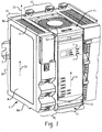
- FIG. 1 shows an electronics module according to an embodiment of the present development, which is shown herein as an industrial automation controller C mounted to an associated DIN rail D.
- FIG. 2 shows a cross-section view of the controller C, and FIG. 2A provides a greatly enlarged view of detail portion A of FIG. 2 .
- the controller C includes an enclosure or housing H that internally is divided into at least one forced convection chamber FC and at least one passive chamber PC which is located adjacent the forced convection chamber FC in the present embodiment.
- the passive chamber PC can comprise a natural convection chamber that is open or unsealed to allow natural convection airflow CX there through (as shown herein), or the passive chamber PC is closed or sealed to prevent or at least minimize convection airflow there through to prevent or inhibit ingress of contaminants.
- the passive chamber PC comprises an open, internal passive space PS defined by the housing H
- the forced convection chamber FC comprises an open, internal forced convection space FS defined by walls of the housing H. More particularly the internal forced convection space FS is defined by a forced convection housing portion H1 of the housing H, which is shown separately in FIG. 4 .
- the passive chamber PC in the illustrated embodiment comprises a natural convection chamber that provides for passive, convection airflow through its internal passive space PS.
- One or more slots S are defined in top and bottom outer walls TW,BW of the housing H or elsewhere in the housing and provide fluid communication between the ambient atmosphere surrounding the housing H and the internal passive space PS of the passive chamber PC to allow air to flow through the natural or passive convection chamber PC due to unassisted convection as indicated by the arrows CX.
- the slots S are omitted or blocked so that the passive chamber PC is closed or sealed to prevent or at least minimize convection airflow through the internal space PS thereof, and also to prevent or at least inhibit ingress of airborne contaminants such as moisture, dust, oil, vapors, and the like.
- the forced convection chamber FC defined by the controller housing H includes at least one active fan F1,F2 that induces forced airflow (as indicated by the arrows FX) through the internal forced convection space FS thereof.
- One or more slots S2 are defined in top and bottom outer walls TW,BW of the housing H or elsewhere in the housing and provide fluid communication between the ambient atmosphere surrounding the housing H and the internal forced convection space FS of the forced convection chamber FC to allow the forced airflow FX to enter and exit the forced convection space FS.
- the controller comprises a first (upper/exhaust) fan Fl and a second (lower/intake) fan F2 that induces forced airflow FX through the internal space FS of the forced convection chamber FC.
- the fans F1,F2 are preferably operated to move air in the same single direction, with the first (upper) fan F1 operated to exhaust air from the internal space FS and the second (lower) fan operated to intake ambient air into the internal space FS to provide the forced convection airflow FX.
- the processor MP and other electronic components of the printed circuit board assembly P1 generate heat that sometimes cannot be dissipated sufficiently by the natural convection airflow CX, but it is undesirable as noted above to subject the printed circuit board assembly P1 to direct fan-forced airflow for cooling.
- the controller C or other electronics module structured according to the present development comprises a heat sink HS, which is also shown separately in FIG. 3 .
- the heat sink HS When operatively installed to the housing H, the heat sink HS is partially located in the passive chamber PC or at least exposed to the passive space PS of the passive chamber PC and partially located in the forced convection chamber FC or at least exposed to the forced convection space FS of the forced convection chamber FC.
- a base HB or heat input region or heat input portion HI of the heat sink HS is located in or at least exposed to the passive space PS, and the heat sink base HB is operatively thermally engaged with the processor MP or at least one other electronic component EC of the printed circuit board assembly P1 such that the processor MP or other electronic components EC of the printed circuit board P1 conduct heat directly into the heat sink base HB through an uninterrupted, continuous thermal pathway as described below.
- the heat sink base HB comprises an outer wall HBW that is exposed to the internal passive space PS of the passive chamber PC and that is located adjacent and thermally engaged with at least one electronic component EC (preferably the processor MP) of the printed circuit board assembly P1.
- the heat sink HS further comprises a heat output portion HO such as a cooling fin structure CFS including a plurality of spaced apart cooling fins CF or other large surface structures connected to and projecting outwardly away from the base HB.
- the heat sink HS is provided by a one-piece aluminum structure or other metallic or other thermally conductive material constructed in one-piece or fabricated from multiple pieces.
- the cooling fin structure CFS or other heat output portion HO is located in and/or exposed to the internal forced convection space FS of the forced convection chamber FC such that the cooling fin structure CFS or other heat output portion HO is exposed to the fan-induced forced airflow FX moving through the internal space FS of the forced convection chamber FC.
- FIG. 4 shows the forced convection portion H1 of the housing H that defines the forced convection chamber FC including the internal forced convection space FS thereof.
- the housing portion H1 includes a heat sink access opening or an open heat sink access window HW located between and providing access between the internal space PS of the passive chamber PC and the internal space FS of the forced convection chamber FC.
- the housing portion H1 defines a perimeter PR of the heat sink access opening HW that extends peripherally around the heat access opening.
- the heat sink HS is operatively installed in the access opening HW such that the heat output portion HO (cooling fins CF of the cooling fin structure CFS) extend through the heat sink access opening HW so as to be located in the internal space FS of the forced convection chamber FC, and such that the base HB of the heat sink is located in and blocks the heat sink access opening HW.
- the outer wall HBW or other part of the heat sink base HB is at least partially located in the internal space PS of the passive chamber PC or the outer wall HBW or other part of the heat sink base HB is at least exposed to the internal space PS of the passive chamber PC so that the outer wall HBW or other part of the base HB is accessible for thermal engagement with the processor MP or other electronic component EC of the main printed circuit board assembly P1.
- the heat sink base HB comprises a flange HF that projects outwardly from the base HB and abuts the forced convection housing portion H1 in the region of the perimeter PR of the heat sink access opening HW when the heat sink HS is operatively installed in the heat sink access opening HW.
- a foam, elastomeric, or other gasket or seal HG extends continuously around the heat sink access opening HW and/or flange HF between the housing portion H1 and the flange HF and sealingly engages the heat sink flange HF to the housing portion H1 at the perimeter of the access opening HW to prevent the fan-forced airflow FX in the internal forced convection space FS from flowing through the access opening HW into the internal space PS of the passive chamber NC as would undesirably expose the printed circuit board P1 to forced convection airflow FX.
- the structure of the present development thus ensures that the portion of the heat sink base HB located in and/or exposed to the passive space PS is separated or isolated in terms of airflow from the cooling fins CF or other heat output portion HO of the heat sink HS that is located in the forced convection space FS by the flange HF or other portion of the heat sink HS that blocks and seals the access opening HW.
- the flange HF or other part of the heat sink base HB includes a plurality of base mounting structures or mounting locations BT that include an aperture or that are otherwise adapted to receive a screw or other fastener FB (one shown in FIG. 6 ) that is threaded into or otherwise engaged with the forced convection housing H1 in the region of the access opening perimeter PR.
- the electronic components of the printed circuit board assembly P1 are abutted and thermally engaged with the base HB of the heat sink such that heat is conducted into the base HB, and from the base HB into the cooling fin structure CFS or other heat output portion HO.
- the forced airflow FX induced by the fans F1,F2 and moving through the interior space FS of the forced convection chamber FC and over the cooling fins CF provides highly efficient cooling while being isolated from the printed circuit board P1 which is located entirely in the interior space PS of the passive chamber PC. As such, the printed circuit board P1 is isolated from and protected from the forced airflow FX.
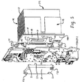
- FIGS. 5 and 6 are exploded views that shows the heat sink HS and main printed circuit board assembly P1 and a clamping plate CP used to operatively and fixedly secure the printed circuit board assembly P1 to the heat sink HS for effective thermal coupling of the processor MP of the printed circuit board assembly P1 to the heat sink base HB.
- the controller housing H and other structures are not shown in FIGS. 5 - 8B .
- the heat sink HS includes first and second (at least two) standoff mounts M1,M2, and first and second (at least two) alignment pins P1,P2, all projecting outwardly from the outer wall HBW of the base HB in a direction opposite or away from the heat output portion HO (cooling fin structure CFS).
- the standoff mounts M1,M2 and alignment pins P1,P2 are together arranged in a rectangular pattern, with the standoff mounts M1,M2 being diagonally located relative to each other and with the alignment pins P1,P2 being diagonally located relative to each other to provide optimum clamping force distribution as described below.
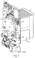
- FIG. 7 is an isometric view that shows the printed circuit board assembly P1 operably connected or assembled to the base HB of the heat sink HS using the clamping plate CP.
- the clamping plate CP is provided by an aluminum or other metallic or polymeric or other rigid plate structure.
- FIG. 8A is a side view that shows the PCBA assembled to the heat sink HS using the clamping plate CP.
- FIG. 8B is a section view taken at B-B of FIG. 8A .
- the standoff mounts M1,M2 extend through standoff apertures or standoff holes MH of the printed circuit board assembly P1.
- the standoff mounts M1,M2 are preferably internally or otherwise threaded.
- the alignment pins P1,P2 extend through alignment apertures or alignment holes PH in the printed circuit board assembly P1 to ensure that the printed circuit board assembly P1 is properly aligned and position with respect to the with the heat sink base HB.
- a resilient thermal interface pad TP FIG.
- the thermal interface pad TP is properly operatively located between the processor MP and heat sink base HB as required for the processor MP to be thermally coupled to the thermal interface pad TP and to the heat sink base HB through the thermal interface pad TP.
- the thermal interface pad comprises a silicone based or other polymeric or elastomeric substrate including ceramic particles or other thermally conductive material therein.
- the thermal interface pad TP need not be preformed and can alternatively be formed in place by application of a layer of the thermally conductive material between the heat sink base HB and the processor MP or other electronic component EC thermally coupled to the heat sink base HB.
- the alignment pins P1,P2 also extend through apertures or holes CH defined in the clamping plate CP (see FIGS. 5 , 7 , 8A ).
- Clamping plate fastening screws or other clamping plate fasteners FS1,FS2 are used to secure the clamping plate CP to the standoff mounts M1,M2 to connect the clamping plate CP to the standoff mounts M1,M2 of the heat sink HS.
- the clamping plate fastening screws/fasteners FS1,FS2 can be captured to the clamping plate or are separate components that are inserted through corresponding fastener apertures FA defined in the clamping plate CP.
- the clamping plate fasteners FS1,FS2 are threadably engaged with the internal or other threads of the respective standoff mounts M1,M2.
- the printed circuit board assembly P1 is thus captured to the heat sink HS adjacent the base HB.
- he printed circuit board assembly P1 is captured between the heat sink base HB on one side and the clamping plate CP on the opposite side.
- the standoff mounts M1,M2 engage the inner face CP1 of the clamping plate to maintain a select standoff distance between the inner face CP1 of the clamping plate CP and the heat sink base HB to prevent over-tightening or over-advancement of the clamping plate CP relative to the heat sink base HB as would increase the clamping force CLX above a desired limit that could cause damage to the processor MP and/or other parts of the printed circuit board assembly P1.
- the clamping plate CP includes an inner face CP1 that is oriented toward the printed circuit board assembly P1 and that includes a resilient, compliant spring member or spring CS such as an elastomeric spring or another suitable resilient member that applies a clamping force CLX directly to the die PD ( FIG. 5 ) of the processor MP on the side of the printed circuit board assembly P1 oriented away from the heat sink base HB when the clamping plate CP is operatively secured to the heat sink HS.
- a resilient, compliant spring member or spring CS such as an elastomeric spring or another suitable resilient member that applies a clamping force CLX directly to the die PD ( FIG. 5 ) of the processor MP on the side of the printed circuit board assembly P1 oriented away from the heat sink base HB when the clamping plate CP is operatively secured to the heat sink HS.
- the spring CS applies the clamping force CLX to the die PD of the processor MP with a known spring rate such that the spring CS compensates for tolerance stack conditions to ensure that excessive clamping force is not exerted on the processor MP by the clamping plate CP as could cause damage to the processor MP or other part of the printed circuit board assembly P1.
- the clamping plate CP is operatively installed and secured to the heat sink base HB using the clamping plate fasteners FS1,FS2, the clamping plate CP and spring CS urge the processor MP into engagement with the heat sink base HB through the thermal pad TP to provide a highly effective and efficient thermal coupling between the processor MP and the heat sink base HB by way of the thermal pad TP.
- clamping plate CP applies clamping force CLX only through the spring CS and the die of the microprocessor MP, which ensures that the printed circuit board assembly P1, itself, is not compressed, bent or flexed as could induce undesired and potentially damaging bending stresses in the printed circuit board assembly P1 and the processor MP.
- the present development thus results in the ball grid array (BGA) solder joints of the processor MP being loaded substantially in compression instead of the transverse shear they would otherwise experience if a force were applied to the printed circuit board in a location that would cause bending stress.
- the present development thus provides a means of creating and maintaining a pre-determined force CLX between a processor die PD and a heat sink HS directly across a printed circuit board assembly P1 and the processor MP instead of inducing bending stress in the printed circuit board assembly P1 and solder joints of the processor MP. This is advantageous because the strength of BGA solder joints on a microprocessor package is higher in compression than in transverse shear.
- the clamping force CLX is applied by a compliant member CS with a known spring rate.
- the spring rate is chosen such that the clamping force CFX applied is within the processor manufacturer's recommendation across the range of deflection resulting from component tolerances (e.g. printed circuit board thickness, component heights, final soldered joint height).
- component tolerances e.g. printed circuit board thickness, component heights, final soldered joint height.
- the present method for operatively securing a heat sink HS in intimate contact with a processor or other electronic component for optimum thermal transfer facilitates use of a very thin thermal interface TP material between the processor MP and the heat sink HS because the assembly is relatively insensitive to the tolerance stackup of system components. This allows higher heat dissipation to the heat sink HS and external environment and therefore processor performance than otherwise available in a correspondingly sized product operating in high ambient temperature conditions. In certain embodiments, this present development also allows for greater component and trace density on the printed circuit board assembly P1 because somewhat less space or "real estate" on the printed circuit board assembly P1 is reserved for heat sink attachment hardware which would otherwise be required. In other words the present clamping system minimizes the space on the printed circuit board assembly P1 required for engaging and retaining the heat sink HS in thermal contact with the processor MP.
Landscapes
- Engineering & Computer Science (AREA)
- Microelectronics & Electronic Packaging (AREA)
- Physics & Mathematics (AREA)
- Thermal Sciences (AREA)
- Mechanical Engineering (AREA)
- General Engineering & Computer Science (AREA)
- Automation & Control Theory (AREA)
- Cooling Or The Like Of Electrical Apparatus (AREA)
- Structures Of Non-Positive Displacement Pumps (AREA)
Abstract
Description
- This application claims priority from and benefit of the filing date of
U.S. provisional patent application Ser. No. 62/418,595 filed November 7, 2016 - Certain industrial automation controllers utilize a high-speed microprocessor (processor) and other components that generate heat beyond that which can be dissipated sufficiently using natural convection airflow. In such cases, the controller must utilize a fan to flow forced air through the controller housing in which the processor is located to cool the processor.
- Use of a fan to cool an industrial automation controller has drawbacks including fan reliability and the tendency of the fan to draw contaminants into the controller housing including dust, dirt, moisture, corrosive particles, and other undesired particulates and contaminants that can damage the controller and degrade its performance over time and lead to a shorter operational life.
- It is not unusual for industrial electronic devices to be used in environments with abnormally high levels of atmospheric contaminants. Printed circuit boards and their electronic components subjected to such atmospheres are often subject to shorter operational life because the contaminants may cause corrosion, short circuits, open circuits, unintended changes in impedances, etc. A device which requires forced convection for adequate cooling will expose the printed circuit board assembly (PCBA) to orders of magnitude greater airflow and atmospheric contaminants than a device which requires only natural convection for equivalent cooling.
- The method typically used to solve this problem is conformal coating which adds a layer of protective material over sensitive areas of the printed circuit board and selected components. Challenges of employing conformal coating include: high cost due to material usage/process time/inspection/rework, difficulty in achieving complete coverage, difficulty in not applying material to areas like contacts or mating connectors, and difficulty in repairing PCBAs after coating. Designing for a more robust conformal coating process outcome typically results in inefficient use of printed circuit board (PCB) real estate (i.e. a larger product than desired or otherwise possible).
- In certain known arrangements, a heat sink is attached to the processor or other heat-generating components on the PCBA to aid in cooling the device to which the heat sink is attached. Maintaining expected levels of reliability in a compact size requires an effective cooling interface between the processor and a heat sink without adding undue stress to processor solder joints or other components on a densely populated PCBA in an industrial environment wherein the PCBA is subjected to vibration, mechanical shock, and other harsh conditions. Known systems have been suboptimal in terms of providing an effective interface between the heat sink and processor or other component on the PCBA, without over stressing the solder joints and other portions of the PCBA.
- In accordance with a first aspect of the present development, an electronics module includes a housing with: (i) a forced convection chamber including an internal forced convection space; and, (ii) a passive chamber including an internal passive space that is separated from the forced convection space of the forced convection chamber. At least one fan is connected to the housing and adapted to induce forced convection airflow in the forced convection space. A heat sink is connected to the housing and includes: (i) a heat input portion exposed to the passive space; and, (ii) a heat output portion exposed to the forced convection space. A circuit board assembly is located in the passive space and includes at least one electronic component that is thermally engaged with the heat input portion of the heat sink.
- In accordance with another aspect of the present development, a heat sink subassembly includes a heat sink with base and a heat output region connected to the base. A clamping plate is secured to the heat sink base. A circuit board is captured adjacent the heat sink base by the clamping plate.
-
-
FIG. 1 shows an industrial automation controller according to the present development mounted to a DIN rail; -
FIG. 2 shows a section view of the controller ofFIG. 1 ; -
FIG. 2A provides a greatly enlarged detail view of portion A ofFIG. 2 ; -
FIG. 3 is an isometric view that shown an example of a heat sink provided as part of the controller ofFIG. 1 ; -
FIG. 4 shows a forced convection portion of a controller housing for the controller ofFIG. 1 ; -
FIGS. 5 and6 are respective exploded isometric view that shows the heat sink ofFIG. 3 , a main circuit board PCBA, and a clamping plate CP used to secure the main circuit board PCBA operatively to the heat sink; -
FIG. 7 is an assembled isometric view that shows the main circuit board PCBA (P1) assembled to the heat sink using the clamping plate to provide a heat sink subassembly; -
FIG. 8A is a side view of the heat sink subassembly ofFIG. 7 ; -
FIG. 8B is a section view taken at B - B ofFIG. 8A . -
FIG. 1 shows an electronics module according to an embodiment of the present development, which is shown herein as an industrial automation controller C mounted to an associated DIN rail D.FIG. 2 shows a cross-section view of the controller C, andFIG. 2A provides a greatly enlarged view of detail portion A ofFIG. 2 . - The controller C includes an enclosure or housing H that internally is divided into at least one forced convection chamber FC and at least one passive chamber PC which is located adjacent the forced convection chamber FC in the present embodiment. As described in further detail below, the passive chamber PC can comprise a natural convection chamber that is open or unsealed to allow natural convection airflow CX there through (as shown herein), or the passive chamber PC is closed or sealed to prevent or at least minimize convection airflow there through to prevent or inhibit ingress of contaminants. As can be seen in
FIG. 2 , the passive chamber PC comprises an open, internal passive space PS defined by the housing H, and the forced convection chamber FC comprises an open, internal forced convection space FS defined by walls of the housing H. More particularly the internal forced convection space FS is defined by a forced convection housing portion H1 of the housing H, which is shown separately inFIG. 4 . - As noted above, the passive chamber PC in the illustrated embodiment comprises a natural convection chamber that provides for passive, convection airflow through its internal passive space PS. One or more slots S are defined in top and bottom outer walls TW,BW of the housing H or elsewhere in the housing and provide fluid communication between the ambient atmosphere surrounding the housing H and the internal passive space PS of the passive chamber PC to allow air to flow through the natural or passive convection chamber PC due to unassisted convection as indicated by the arrows CX. Alternatively, the slots S are omitted or blocked so that the passive chamber PC is closed or sealed to prevent or at least minimize convection airflow through the internal space PS thereof, and also to prevent or at least inhibit ingress of airborne contaminants such as moisture, dust, oil, vapors, and the like.
- The forced convection chamber FC defined by the controller housing H includes at least one active fan F1,F2 that induces forced airflow (as indicated by the arrows FX) through the internal forced convection space FS thereof. One or more slots S2 are defined in top and bottom outer walls TW,BW of the housing H or elsewhere in the housing and provide fluid communication between the ambient atmosphere surrounding the housing H and the internal forced convection space FS of the forced convection chamber FC to allow the forced airflow FX to enter and exit the forced convection space FS. In the illustrated embodiment, the controller comprises a first (upper/exhaust) fan Fl and a second (lower/intake) fan F2 that induces forced airflow FX through the internal space FS of the forced convection chamber FC. The fans F1,F2 are preferably operated to move air in the same single direction, with the first (upper) fan F1 operated to exhaust air from the internal space FS and the second (lower) fan operated to intake ambient air into the internal space FS to provide the forced convection airflow FX.
- A main or primary printed circuit board assembly (PCBA) P1 including electronic components EC comprising a CPU processor MP (see
FIGS. 2 &6 ) and related electronic components is operatively located in the internal space PS of the passive chamber PC. The processor MP and other electronic components of the printed circuit board assembly P1 generate heat that sometimes cannot be dissipated sufficiently by the natural convection airflow CX, but it is undesirable as noted above to subject the printed circuit board assembly P1 to direct fan-forced airflow for cooling. - Instead, according to the present development, the controller C or other electronics module structured according to the present development comprises a heat sink HS, which is also shown separately in
FIG. 3 . When operatively installed to the housing H, the heat sink HS is partially located in the passive chamber PC or at least exposed to the passive space PS of the passive chamber PC and partially located in the forced convection chamber FC or at least exposed to the forced convection space FS of the forced convection chamber FC. In particular, a base HB or heat input region or heat input portion HI of the heat sink HS is located in or at least exposed to the passive space PS, and the heat sink base HB is operatively thermally engaged with the processor MP or at least one other electronic component EC of the printed circuit board assembly P1 such that the processor MP or other electronic components EC of the printed circuit board P1 conduct heat directly into the heat sink base HB through an uninterrupted, continuous thermal pathway as described below. In the illustrated embodiment, the heat sink base HB comprises an outer wall HBW that is exposed to the internal passive space PS of the passive chamber PC and that is located adjacent and thermally engaged with at least one electronic component EC (preferably the processor MP) of the printed circuit board assembly P1. - The heat sink HS further comprises a heat output portion HO such as a cooling fin structure CFS including a plurality of spaced apart cooling fins CF or other large surface structures connected to and projecting outwardly away from the base HB. The heat sink HS is provided by a one-piece aluminum structure or other metallic or other thermally conductive material constructed in one-piece or fabricated from multiple pieces.
- As shown in
FIG. 2 , when the heat sink HS is operatively installed in the housing H of the controller C, the cooling fin structure CFS or other heat output portion HO is located in and/or exposed to the internal forced convection space FS of the forced convection chamber FC such that the cooling fin structure CFS or other heat output portion HO is exposed to the fan-induced forced airflow FX moving through the internal space FS of the forced convection chamber FC. -
FIG. 4 shows the forced convection portion H1 of the housing H that defines the forced convection chamber FC including the internal forced convection space FS thereof. Referring also toFIGS. 2 and2A , the housing portion H1 includes a heat sink access opening or an open heat sink access window HW located between and providing access between the internal space PS of the passive chamber PC and the internal space FS of the forced convection chamber FC. The housing portion H1 defines a perimeter PR of the heat sink access opening HW that extends peripherally around the heat access opening. The heat sink HS is operatively installed in the access opening HW such that the heat output portion HO (cooling fins CF of the cooling fin structure CFS) extend through the heat sink access opening HW so as to be located in the internal space FS of the forced convection chamber FC, and such that the base HB of the heat sink is located in and blocks the heat sink access opening HW. The outer wall HBW or other part of the heat sink base HB is at least partially located in the internal space PS of the passive chamber PC or the outer wall HBW or other part of the heat sink base HB is at least exposed to the internal space PS of the passive chamber PC so that the outer wall HBW or other part of the base HB is accessible for thermal engagement with the processor MP or other electronic component EC of the main printed circuit board assembly P1. The heat sink base HB comprises a flange HF that projects outwardly from the base HB and abuts the forced convection housing portion H1 in the region of the perimeter PR of the heat sink access opening HW when the heat sink HS is operatively installed in the heat sink access opening HW. A foam, elastomeric, or other gasket or seal HG extends continuously around the heat sink access opening HW and/or flange HF between the housing portion H1 and the flange HF and sealingly engages the heat sink flange HF to the housing portion H1 at the perimeter of the access opening HW to prevent the fan-forced airflow FX in the internal forced convection space FS from flowing through the access opening HW into the internal space PS of the passive chamber NC as would undesirably expose the printed circuit board P1 to forced convection airflow FX. The structure of the present development thus ensures that the portion of the heat sink base HB located in and/or exposed to the passive space PS is separated or isolated in terms of airflow from the cooling fins CF or other heat output portion HO of the heat sink HS that is located in the forced convection space FS by the flange HF or other portion of the heat sink HS that blocks and seals the access opening HW. To facilitate an airtight seal between the flange HF and the perimeter PR of the access opening HW, the flange HF or other part of the heat sink base HB includes a plurality of base mounting structures or mounting locations BT that include an aperture or that are otherwise adapted to receive a screw or other fastener FB (one shown inFIG. 6 ) that is threaded into or otherwise engaged with the forced convection housing H1 in the region of the access opening perimeter PR. - As noted above, at least some of the electronic components of the printed circuit board assembly P1 are abutted and thermally engaged with the base HB of the heat sink such that heat is conducted into the base HB, and from the base HB into the cooling fin structure CFS or other heat output portion HO. The forced airflow FX induced by the fans F1,F2 and moving through the interior space FS of the forced convection chamber FC and over the cooling fins CF provides highly efficient cooling while being isolated from the printed circuit board P1 which is located entirely in the interior space PS of the passive chamber PC. As such, the printed circuit board P1 is isolated from and protected from the forced airflow FX.
-
FIGS. 5 and6 are exploded views that shows the heat sink HS and main printed circuit board assembly P1 and a clamping plate CP used to operatively and fixedly secure the printed circuit board assembly P1 to the heat sink HS for effective thermal coupling of the processor MP of the printed circuit board assembly P1 to the heat sink base HB. The controller housing H and other structures are not shown inFIGS. 5 - 8B . - In the illustrated embodiment, the heat sink HS includes first and second (at least two) standoff mounts M1,M2, and first and second (at least two) alignment pins P1,P2, all projecting outwardly from the outer wall HBW of the base HB in a direction opposite or away from the heat output portion HO (cooling fin structure CFS). The standoff mounts M1,M2 and alignment pins P1,P2 are together arranged in a rectangular pattern, with the standoff mounts M1,M2 being diagonally located relative to each other and with the alignment pins P1,P2 being diagonally located relative to each other to provide optimum clamping force distribution as described below.
-
FIG. 7 is an isometric view that shows the printed circuit board assembly P1 operably connected or assembled to the base HB of the heat sink HS using the clamping plate CP. The clamping plate CP is provided by an aluminum or other metallic or polymeric or other rigid plate structure.FIG. 8A is a side view that shows the PCBA assembled to the heat sink HS using the clamping plate CP.FIG. 8B is a section view taken at B-B ofFIG. 8A . - The standoff mounts M1,M2 extend through standoff apertures or standoff holes MH of the printed circuit board assembly P1. The standoff mounts M1,M2 are preferably internally or otherwise threaded. Likewise, the alignment pins P1,P2 extend through alignment apertures or alignment holes PH in the printed circuit board assembly P1 to ensure that the printed circuit board assembly P1 is properly aligned and position with respect to the with the heat sink base HB. A resilient thermal interface pad TP (
FIG. 3 ) is adhesively or otherwise secured to the heat sink base HB and/or to the processor MP, and engagement of the alignment pins P1,P2 with the respective alignment holes PH of the printed circuit board assembly P1 ensures that the thermal interface pad TP is properly operatively located between the processor MP and heat sink base HB as required for the processor MP to be thermally coupled to the thermal interface pad TP and to the heat sink base HB through the thermal interface pad TP. In one embodiment the thermal interface pad comprises a silicone based or other polymeric or elastomeric substrate including ceramic particles or other thermally conductive material therein. The thermal interface pad TP need not be preformed and can alternatively be formed in place by application of a layer of the thermally conductive material between the heat sink base HB and the processor MP or other electronic component EC thermally coupled to the heat sink base HB. - To ensure proper location of the clamping plate CP, the alignment pins P1,P2 also extend through apertures or holes CH defined in the clamping plate CP (see
FIGS. 5 ,7 ,8A ). Clamping plate fastening screws or other clamping plate fasteners FS1,FS2 are used to secure the clamping plate CP to the standoff mounts M1,M2 to connect the clamping plate CP to the standoff mounts M1,M2 of the heat sink HS. The clamping plate fastening screws/fasteners FS1,FS2 can be captured to the clamping plate or are separate components that are inserted through corresponding fastener apertures FA defined in the clamping plate CP. In the illustrated embodiment, the clamping plate fasteners FS1,FS2 are threadably engaged with the internal or other threads of the respective standoff mounts M1,M2. The printed circuit board assembly P1 is thus captured to the heat sink HS adjacent the base HB. In particular, he printed circuit board assembly P1 is captured between the heat sink base HB on one side and the clamping plate CP on the opposite side. The standoff mounts M1,M2 engage the inner face CP1 of the clamping plate to maintain a select standoff distance between the inner face CP1 of the clamping plate CP and the heat sink base HB to prevent over-tightening or over-advancement of the clamping plate CP relative to the heat sink base HB as would increase the clamping force CLX above a desired limit that could cause damage to the processor MP and/or other parts of the printed circuit board assembly P1. - As shown in
FIGS. 6 and8B , the clamping plate CP includes an inner face CP1 that is oriented toward the printed circuit board assembly P1 and that includes a resilient, compliant spring member or spring CS such as an elastomeric spring or another suitable resilient member that applies a clamping force CLX directly to the die PD (FIG. 5 ) of the processor MP on the side of the printed circuit board assembly P1 oriented away from the heat sink base HB when the clamping plate CP is operatively secured to the heat sink HS. The spring CS applies the clamping force CLX to the die PD of the processor MP with a known spring rate such that the spring CS compensates for tolerance stack conditions to ensure that excessive clamping force is not exerted on the processor MP by the clamping plate CP as could cause damage to the processor MP or other part of the printed circuit board assembly P1. When the clamping plate CP is operatively installed and secured to the heat sink base HB using the clamping plate fasteners FS1,FS2, the clamping plate CP and spring CS urge the processor MP into engagement with the heat sink base HB through the thermal pad TP to provide a highly effective and efficient thermal coupling between the processor MP and the heat sink base HB by way of the thermal pad TP. It should be noted that the clamping plate CP applies clamping force CLX only through the spring CS and the die of the microprocessor MP, which ensures that the printed circuit board assembly P1, itself, is not compressed, bent or flexed as could induce undesired and potentially damaging bending stresses in the printed circuit board assembly P1 and the processor MP. - The present development thus results in the ball grid array (BGA) solder joints of the processor MP being loaded substantially in compression instead of the transverse shear they would otherwise experience if a force were applied to the printed circuit board in a location that would cause bending stress. The present development thus provides a means of creating and maintaining a pre-determined force CLX between a processor die PD and a heat sink HS directly across a printed circuit board assembly P1 and the processor MP instead of inducing bending stress in the printed circuit board assembly P1 and solder joints of the processor MP. This is advantageous because the strength of BGA solder joints on a microprocessor package is higher in compression than in transverse shear.
- External stress from operating in an industrial environment (e.g. mechanical shock, vibration) typically results in additional bending (i.e. transverse shear stress) of the printed circuit board assembly P1. Extra operating stress margin is provided by the present development by reducing or eliminating what would otherwise be a "pre-load" of transverse shear created by more typically used heat sink mounting methods and structures.
- The clamping force CLX is applied by a compliant member CS with a known spring rate. The spring rate is chosen such that the clamping force CFX applied is within the processor manufacturer's recommendation across the range of deflection resulting from component tolerances (e.g. printed circuit board thickness, component heights, final soldered joint height). The present development provides a means of creating and maintaining a pre-determined force between a processor die PD and a heat sink HS directly across a printed circuit board assembly P1 and the processor MP instead of inducing bending stress in the printed circuit board assembly P1 and processor MP.
- The present method for operatively securing a heat sink HS in intimate contact with a processor or other electronic component for optimum thermal transfer facilitates use of a very thin thermal interface TP material between the processor MP and the heat sink HS because the assembly is relatively insensitive to the tolerance stackup of system components. This allows higher heat dissipation to the heat sink HS and external environment and therefore processor performance than otherwise available in a correspondingly sized product operating in high ambient temperature conditions. In certain embodiments, this present development also allows for greater component and trace density on the printed circuit board assembly P1 because somewhat less space or "real estate" on the printed circuit board assembly P1 is reserved for heat sink attachment hardware which would otherwise be required. In other words the present clamping system minimizes the space on the printed circuit board assembly P1 required for engaging and retaining the heat sink HS in thermal contact with the processor MP.
- In the preceding specification, various embodiments have been described with reference to the accompanying drawings. It will, however, be evident that various modifications and changes may be made thereto, and additional embodiments may be implemented, without departing from the broader scope of the invention as set forth in the claims that follow. The specification and drawings are accordingly to be regarded in an illustrative rather than restrictive sense.
- The following is a list of further preferred embodiments of the invention:
-
Embodiment 1. An electronics module comprising:- a housing comprising: (i) a forced convection chamber including an internal forced convection space; and, (ii) a passive chamber including an internal passive space that is separated from the forced convection space of the forced convection chamber;
- at least one fan connected to the housing and adapted to induce forced convection airflow in the forced convection space;
- a heat sink connected to the housing, said heat sink comprising: (i) a heat input portion exposed to the passive space of the passive chamber; and, (ii) a heat output portion exposed to the forced convection space of the forced convection chamber;
- a circuit board assembly located in the passive space, said circuit board assembly comprising at least one electronic component that is thermally engaged with the heat input portion of the heat sink.
-
Embodiment 2. The electronics module as set forth inembodiment 1, wherein said housing comprises a heat sink access opening that provides access between the forced convection space and the passive space, and wherein said heat sink is installed in said heat sink access opening and blocks airflow between the forced convection space and the passive space. - Embodiment 3. The electronics module as set forth in
embodiment 2, wherein said housing defines a perimeter of the heat sink access opening, and wherein the heat sink comprises a flange that is abutted with the perimeter of the heat sink access opening. - Embodiment 4. The electronics module as set forth in embodiment 3, further comprising a gasket located between the flange and the perimeter of the heat sink access opening.
- Embodiment 5. The electronics module as set forth in
embodiment 1, wherein the heat output portion of the heat sink comprises a plurality of cooling fins that are located in the forced convection chamber. - Embodiment 6. The electronics module as set forth in
embodiment 1, wherein the housing includes a plurality of slots defined therein that provide communication between an ambient atmosphere surrounding the housing H and the passive space of the passive chamber such that said passive chamber allows natural convection airflow through the passive space thereof. - Embodiment 7. The electronics module as set forth in
embodiment 1, wherein said heat input portion of said heat sink comprises a base of said heat sink, and wherein said circuit board assembly is secured to the heat sink base. -
Embodiment 8. The electronics module as set forth in embodiment 7, further comprising a clamping plate secured to the heat sink base, wherein said circuit board assembly is captured between the clamping plate and an outer wall of the heat sink base to secure the circuit board assembly to the heat sink base. - Embodiment 9. The electronics module as set forth in
embodiment 8, further comprising a resilient spring located between the clamping plate and the circuit board assembly. - Embodiment 10. The electronics module as set forth in embodiment 9, wherein said spring comprises an elastomeric spring.
- Embodiment 11. The electronics module as set forth in embodiment 9, further comprising first and second standoff mounts that project outwardly from the heat sink base, and wherein said clamping plate is secured to the first and second standoff mounts to maintain a select standoff distance between the clamping plate and the heat sink base.
- Embodiment 12. The electronics module as set forth in
embodiment 8, further comprising a resilient thermally conductive material located between the outer wall of the heat sink base and said at least one electronic component that is thermally engaged with the heat input portion of the heat sink. - Embodiment 13. A heat sink subassembly comprising:
- a heat sink including a base and a heat output region connected to the base;
- a clamping plate secured to the heat sink base;
- a circuit board captured adjacent the heat sink base by said clamping plate.
- Embodiment 14. The subassembly as set forth in embodiment 13, further comprising a resilient spring located between the clamping plate and the circuit board.
- Embodiment 15. The subassembly as set forth in embodiment 13, further comprising a thermally conductive resilient material located between the circuit board and the heat sink base.
- Embodiment 16. The subassembly as set forth in embodiment 13, further comprising at least two standoff mounts that project outwardly from the base, and wherein the clamping plate is secured to the standoff mounts such that a standoff distance is maintained between the clamping plate and the heat sink base.
- Embodiment 17. The subassembly as set forth in embodiment 16, wherein said at least two standoff mounts are diagonally located relative to each other.
- Embodiment 18. The subassembly as set forth in embodiment 17, wherein said at least two standoff mounts are each internally threaded and wherein said heat sink subassembly further comprises fasteners that extend through the clamping plate and that are respectively threadably engaged with the at least two standoff mounts to secure the clamping plate to the standoff mounts.
- Embodiment 19. The subassembly as set forth in embodiment 16, further comprising at least two alignment pins that project outwardly from the base, wherein said alignment pins each extend through respective openings defined in the circuit board and the clamping plate to maintain alignment of the circuit board and the clamping plate relative to the heat sink base.
Claims (15)
- An electronics module comprising:a housing comprising: (i) a forced convection chamber including an internal forced convection space; and, (ii) a passive chamber including an internal passive space that is separated from the forced convection space of the forced convection chamber;at least one fan connected to the housing and adapted to induce forced convection airflow in the forced convection space;a heat sink connected to the housing, said heat sink comprising: (i) a heat input portion exposed to the passive space of the passive chamber; and, (ii) a heat output portion exposed to the forced convection space of the forced convection chamber;a circuit board assembly located in the passive space, said circuit board assembly comprising at least one electronic component that is thermally engaged with the heat input portion of the heat sink.
- The electronics module as set forth in claim 1, wherein said housing comprises a heat sink access opening that provides access between the forced convection space and the passive space, and wherein said heat sink is installed in said heat sink access opening and blocks airflow between the forced convection space and the passive space.
- The electronics module as set forth in claim 2, wherein said housing defines a perimeter of the heat sink access opening, and wherein the heat sink comprises a flange that is abutted with the perimeter of the heat sink access opening, and further comprising a gasket located between the flange and the perimeter of the heat sink access opening.
- The electronics module as set forth in one of claims 1 to 3, wherein:the heat output portion of the heat sink comprises a plurality of cooling fins that are located in the forced convection chamber; and/orwherein the housing includes a plurality of slots defined therein that provide communication between an ambient atmosphere surrounding the housing H and the passive space of the passive chamber such that said passive chamber allows natural convection airflow through the passive space thereof.
- The electronics module as set forth in one of claims 1 to 4, wherein said heat input portion of said heat sink comprises a base of said heat sink, and wherein said circuit board assembly is secured to the heat sink base.
- The electronics module as set forth in claim 5, further comprising a clamping plate secured to the heat sink base, wherein said circuit board assembly is captured between the clamping plate and an outer wall of the heat sink base to secure the circuit board assembly to the heat sink base.
- The electronics module as set forth in claim 6, further comprising a resilient spring located between the clamping plate and the circuit board assembly.
- The electronics module as set forth in claim 7, wherein said spring comprises an elastomeric spring.
- The electronics module as set forth in claim 7, further comprising first and second standoff mounts that project outwardly from the heat sink base, and wherein said clamping plate is secured to the first and second standoff mounts to maintain a select standoff distance between the clamping plate and the heat sink base.
- The electronics module as set forth in claim 6, further comprising a resilient thermally conductive material located between the outer wall of the heat sink base and said at least one electronic component that is thermally engaged with the heat input portion of the heat sink.
- A heat sink subassembly comprising:a heat sink including a base and a heat output region connected to the base;a clamping plate secured to the heat sink base;a circuit board captured adjacent the heat sink base by said clamping plate.
- The subassembly as set forth in claim 11, further comprising:a resilient spring located between the clamping plate and the circuit board; ora thermally conductive resilient material located between the circuit board and the heat sink base.
- The subassembly as set forth in claim 11, further comprising at least two standoff mounts that project outwardly from the base, and wherein the clamping plate is secured to the standoff mounts such that a standoff distance is maintained between the clamping plate and the heat sink base.
- The subassembly as set forth in claim 13, wherein said at least two standoff mounts are diagonally located relative to each other, and wherein said at least two standoff mounts are each internally threaded and wherein said heat sink subassembly further comprises fasteners that extend through the clamping plate and that are respectively threadably engaged with the at least two standoff mounts to secure the clamping plate to the standoff mounts.
- The subassembly as set forth in claim 13, further comprising at least two alignment pins that project outwardly from the base, wherein said alignment pins each extend through respective openings defined in the circuit board and the clamping plate to maintain alignment of the circuit board and the clamping plate relative to the heat sink base.
Applications Claiming Priority (2)
| Application Number | Priority Date | Filing Date | Title |
|---|---|---|---|
| US201662418595P | 2016-11-07 | 2016-11-07 | |
| US15/720,537 US10238004B2 (en) | 2016-11-07 | 2017-09-29 | Controller with enhanced thermal properties |
Publications (2)
| Publication Number | Publication Date |
|---|---|
| EP3373715A1 true EP3373715A1 (en) | 2018-09-12 |
| EP3373715B1 EP3373715B1 (en) | 2021-04-14 |
Family
ID=62064257
Family Applications (2)
| Application Number | Title | Priority Date | Filing Date |
|---|---|---|---|
| EP17200387.3A Active EP3373715B1 (en) | 2016-11-07 | 2017-11-07 | Controller with enhanced thermal properties |
| EP17200384.0A Active EP3361848B1 (en) | 2016-11-07 | 2017-11-07 | Controller with fan monitoring and control |
Family Applications After (1)
| Application Number | Title | Priority Date | Filing Date |
|---|---|---|---|
| EP17200384.0A Active EP3361848B1 (en) | 2016-11-07 | 2017-11-07 | Controller with fan monitoring and control |
Country Status (3)
| Country | Link |
|---|---|
| US (5) | US10390456B2 (en) |
| EP (2) | EP3373715B1 (en) |
| CN (2) | CN108064124A (en) |
Families Citing this family (31)
| Publication number | Priority date | Publication date | Assignee | Title |
|---|---|---|---|---|
| CN109312945B (en) | 2016-06-15 | 2022-03-04 | 亨特风扇公司 | Ceiling fan systems and electronics enclosures |
| US10390456B2 (en) * | 2016-11-07 | 2019-08-20 | Rockwell Automation Technologies, Inc. | Controller with fan monitoring and control |
| JP1605430S (en) * | 2017-11-24 | 2019-05-27 | ||
| JP1605963S (en) * | 2017-11-24 | 2019-05-27 | ||
| JP1605429S (en) * | 2017-11-24 | 2019-05-27 | ||
| JP1605962S (en) * | 2017-11-24 | 2019-05-27 | ||
| US10908270B2 (en) * | 2018-01-18 | 2021-02-02 | Fujifilm Sonosite, Inc. | Portable ultrasound imaging system with active cooling |
| JP6767420B2 (en) | 2018-04-09 | 2020-10-14 | ファナック株式会社 | Motor drive |
| TWI705188B (en) * | 2018-08-01 | 2020-09-21 | 緯創資通股份有限公司 | Fan system and sound suppression method thereof |
| US10648744B2 (en) * | 2018-08-09 | 2020-05-12 | The Boeing Company | Heat transfer devices and methods for facilitating convective heat transfer with a heat source or a cold source |
| KR102671866B1 (en) * | 2019-01-17 | 2024-05-31 | 엘에스일렉트릭(주) | Heatsink module with reduction support-unit against vibration |
| CN109862726A (en) * | 2019-02-21 | 2019-06-07 | 漯河职业技术学院 | A kind of electric automatization protective device |
| CN110056980B (en) * | 2019-03-26 | 2020-11-03 | 青岛海尔空调器有限总公司 | Air conditioner and electric heating control method and control device thereof |
| CN110149779B (en) * | 2019-04-29 | 2020-06-30 | 上海沪工焊接集团股份有限公司 | Machine core support |
| USD904986S1 (en) * | 2019-06-27 | 2020-12-15 | Banner Engineering Corp | Safety controller |
| TWI722731B (en) * | 2019-12-23 | 2021-03-21 | 廣達電腦股份有限公司 | Electronic device and its heat dissipation assembly |
| US11452244B2 (en) * | 2019-12-30 | 2022-09-20 | Microsoft Technology Licensing, Llc | Reverse flow prevention |
| CN111769722B (en) * | 2020-02-28 | 2022-05-17 | 中车青岛四方车辆研究所有限公司 | Traction converter and traction converter control method |
| USD1040802S1 (en) * | 2020-03-20 | 2024-09-03 | Mercury Mission Systems, Llc | Information system housing |
| CN111637079B (en) * | 2020-06-11 | 2021-08-17 | 西安易朴通讯技术有限公司 | Mainboard, fan control system and method |
| BE1028433B1 (en) * | 2020-06-25 | 2022-01-31 | Phoenix Contact Gmbh & Co | Assembly with a heat sink core element forming a support structure |
| US11690195B2 (en) * | 2020-09-11 | 2023-06-27 | Abb Schweiz Ag | Power semiconductor cooling system |
| US20220200213A1 (en) | 2020-12-23 | 2022-06-23 | Caci, Inc. - Federal | Systems, apparatuses, and methods for predicting a state of a card connector |
| CA220261S (en) * | 2021-01-08 | 2023-07-17 | Canaan Creative Co Ltd | Calculating equipment |
| CN214852404U (en) * | 2021-02-06 | 2021-11-23 | 北京图森智途科技有限公司 | a control device |
| TWM618207U (en) * | 2021-05-31 | 2021-10-11 | 和碩聯合科技股份有限公司 | Electronic device |
| JP2023062592A (en) * | 2021-10-21 | 2023-05-08 | キヤノン株式会社 | Electronic apparatus, control method, and program |
| US12422809B2 (en) * | 2022-01-20 | 2025-09-23 | Hewlett Packard Enterprise Development Lp | Fan enhancements to improve server performance and quality |
| GB2619082A (en) * | 2022-05-27 | 2023-11-29 | Nibrotech Ltd | Fan speed control device |
| JP1761816S (en) * | 2023-03-24 | 2024-01-19 | programmable controller | |
| CN117693175B (en) * | 2024-02-04 | 2024-04-16 | 长安绿电科技有限公司 | Quick charging device for lithium battery |
Citations (3)
| Publication number | Priority date | Publication date | Assignee | Title |
|---|---|---|---|---|
| US5642260A (en) * | 1996-01-16 | 1997-06-24 | Illinois Tool Works Inc. | Welding power supply housing |
| JP2008306138A (en) * | 2007-06-11 | 2008-12-18 | Fujitsu Ltd | Mounting board |
| US20100232109A1 (en) * | 2009-03-13 | 2010-09-16 | Fu Zhun Precision Industry (Shen Zhen) Co., Ltd. | Heat dissipation device |
Family Cites Families (80)
| Publication number | Priority date | Publication date | Assignee | Title |
|---|---|---|---|---|
| US5648893A (en) * | 1993-07-30 | 1997-07-15 | Sun Microsystems, Inc. | Upgradable multi-chip module |
| TW432305B (en) * | 1997-03-31 | 2001-05-01 | Hitachi Ltd | Electronic commerce transaction system |
| US6145098A (en) * | 1997-05-13 | 2000-11-07 | Micron Electronics, Inc. | System for displaying system status |
| US7385359B2 (en) * | 1997-08-26 | 2008-06-10 | Philips Solid-State Lighting Solutions, Inc. | Information systems |
| US6222736B1 (en) * | 1999-01-26 | 2001-04-24 | Dell Usa, L.P. | Computer with component installation handle |
| US6459582B1 (en) | 2000-07-19 | 2002-10-01 | Fujitsu Limited | Heatsink apparatus for de-coupling clamping forces on an integrated circuit package |
| US6556437B1 (en) | 2000-08-10 | 2003-04-29 | Dell Products L.P. | Ergonomic carrier for hot-swap computer components |
| US6504721B1 (en) * | 2000-09-29 | 2003-01-07 | Intel Corporation | Thermal cooling apparatus |
| CN2455044Y (en) | 2000-10-23 | 2001-10-17 | 富准精密工业(深圳)有限公司 | Radiating device combination |
| US6592449B2 (en) * | 2001-02-24 | 2003-07-15 | International Business Machines Corporation | Smart fan modules and system |
| US6373698B1 (en) * | 2001-05-03 | 2002-04-16 | International Business Machines Corporation | Apparatus for cooling a computer system |
| US6477053B1 (en) * | 2001-07-17 | 2002-11-05 | Tyco Telecommunications (Us) Inc. | Heat sink and electronic assembly including same |
| US7245632B2 (en) * | 2001-08-10 | 2007-07-17 | Sun Microsystems, Inc. | External storage for modular computer systems |
| US6603661B2 (en) | 2001-12-14 | 2003-08-05 | Hewlett-Packard Development Company, L.P. | Universal fan cage for hot-pluggable fans |
| IL147394A0 (en) * | 2001-12-30 | 2002-08-14 | Active Cool Ltd | Thermoelectric active cooling system for a computer processor with reduced audible noise and emi noise audio noise |
| JP3638269B2 (en) * | 2002-03-14 | 2005-04-13 | 三菱電機株式会社 | Electric power steering device |
| US6708372B2 (en) * | 2002-05-30 | 2004-03-23 | Sun Microsystems, Inc. | Snap-in fan tray ejector and handle |
| US7031155B2 (en) * | 2003-01-06 | 2006-04-18 | Intel Corporation | Electronic thermal management |
| US6885557B2 (en) * | 2003-04-24 | 2005-04-26 | Intel Corporaiton | Heatsink assembly |
| US7233877B2 (en) * | 2003-08-29 | 2007-06-19 | Sun Microsystems, Inc. | System health monitoring |
| US20160325284A1 (en) * | 2003-09-19 | 2016-11-10 | Applied Biosystems, Llc | Pressure Chamber Clamp Mechanism |
| TWM246696U (en) * | 2003-11-18 | 2004-10-11 | Quanta Comp Inc | Removable fan module |
| CN2664185Y (en) * | 2003-11-29 | 2004-12-15 | 鸿富锦精密工业(深圳)有限公司 | Heat sink assembly |
| GB2411050A (en) * | 2004-02-16 | 2005-08-17 | E2V Tech Uk Ltd | Electrical apparatus cooling system |
| CN2752849Y (en) * | 2004-12-30 | 2006-01-18 | 番禺得意精密电子工业有限公司 | Radiator fixer |
| JP4498163B2 (en) * | 2005-02-08 | 2010-07-07 | 株式会社東芝 | Heat dissipation device for electronic equipment |
| US7098617B1 (en) * | 2005-02-16 | 2006-08-29 | Texas Instruments Incorporated | Advanced programmable closed loop fan control method |
| ATE441315T1 (en) * | 2005-06-10 | 2009-09-15 | Ebm Papst St Georgen Gmbh & Co | EQUIPMENT FAN |
| US7486516B2 (en) * | 2005-08-11 | 2009-02-03 | International Business Machines Corporation | Mounting a heat sink in thermal contact with an electronic component |
| CN2819709Y (en) * | 2005-09-01 | 2006-09-20 | 番禺得意精密电子工业有限公司 | Circuit board combination |
| CN2874091Y (en) | 2005-12-30 | 2007-02-28 | 鸿富锦精密工业(深圳)有限公司 | fan mount |
| US7317618B2 (en) * | 2006-03-09 | 2008-01-08 | Laird Technologies, Inc. | Combined board level shielding and thermal management |
| US20070227701A1 (en) * | 2006-03-31 | 2007-10-04 | Bhatti Mohinder S | Thermosiphon with flexible boiler plate |
| GB2439780B (en) * | 2006-07-04 | 2010-12-01 | Anachem Ltd | Controlled environment cabinet |
| CN200962706Y (en) | 2006-10-12 | 2007-10-17 | 英业达股份有限公司 | Cooling fan holder |
| CN200962690Y (en) * | 2006-10-18 | 2007-10-17 | 英业达股份有限公司 | flex-resistant circuit board |
| US20080115914A1 (en) * | 2006-11-17 | 2008-05-22 | Foxconn Technology Co., Ltd. | Heat dissipation device with heat pipes |
| WO2008082392A1 (en) * | 2006-12-29 | 2008-07-10 | Carrier Corporation | Thermoelectric hot/cold pans |
| JP4867727B2 (en) * | 2007-03-13 | 2012-02-01 | パナソニック株式会社 | Cooling system |
| US8202047B2 (en) * | 2007-06-07 | 2012-06-19 | Hewlett-Packard Development Company, L.P. | Fan module latching device |
| CN101351107B (en) * | 2007-07-20 | 2011-06-29 | 富准精密工业(深圳)有限公司 | Back board combination for heat radiator |
| US8677767B2 (en) * | 2008-01-28 | 2014-03-25 | Tayfun Ilercil | Thermo-electric heat pump systems |
| US7675747B1 (en) | 2008-12-10 | 2010-03-09 | Sun Microsystems, Inc. | Reversible, counter-rotating fan modules for a computer chassis |
| JP2010233379A (en) * | 2009-03-27 | 2010-10-14 | Fuji Electric Systems Co Ltd | Power converter |
| US8451600B1 (en) * | 2010-03-04 | 2013-05-28 | Amazon Technologies, Inc. | Heat spreading chassis for rack-mounted computer system |
| EP2364807B1 (en) * | 2010-03-10 | 2013-05-08 | Daihen Corporation | Power supply apparatus including fan for air cooling |
| CN102202485A (en) * | 2010-03-24 | 2011-09-28 | 富瑞精密组件(昆山)有限公司 | Heat-radiating device combination and electronic device employing same |
| CN201690345U (en) | 2010-04-26 | 2010-12-29 | 纬创资通股份有限公司 | Power supply device with heat dissipation function and combination of power supply device and portable electronic device |
| US8472194B2 (en) | 2010-05-05 | 2013-06-25 | Custom Sensors & Technologies, Inc. | Solid state switching device with integral heatsink |
| CN201893684U (en) * | 2010-12-07 | 2011-07-06 | 上海格立特电力电子有限公司 | Frequency changer with separator |
| US20120160454A1 (en) * | 2010-12-23 | 2012-06-28 | Asia Vital Components Co., Ltd. | Heat exchanger |
| JP5614542B2 (en) * | 2011-03-28 | 2014-10-29 | 株式会社安川電機 | Motor control device |
| CN102809997A (en) | 2011-05-31 | 2012-12-05 | 鸿富锦精密工业(深圳)有限公司 | fan mount |
| CN202178167U (en) * | 2011-08-11 | 2012-03-28 | 江苏威凡智能电气科技有限公司 | Thyristor electronic switch |
| CN102981576A (en) * | 2011-09-05 | 2013-03-20 | 鸿富锦精密工业(深圳)有限公司 | Fan module |
| US10670028B2 (en) * | 2011-10-21 | 2020-06-02 | Prime Datum Development Company, Llc | Load bearing direct drive fan system with variable process control |
| US8634193B2 (en) * | 2011-12-05 | 2014-01-21 | Rockwell Automation Technologies, Inc. | Device and method using induction to improve natural convection cooling |
| US9158310B2 (en) * | 2011-12-14 | 2015-10-13 | International Business Machines Corporation | Integrating a data center thermal control system and individual fan controllers for controlling a thermal environment in a data center room |
| WO2013125650A1 (en) * | 2012-02-22 | 2013-08-29 | 富士電機株式会社 | Integrated type air conditioning system, control device therefor |
| US9658629B2 (en) * | 2012-03-22 | 2017-05-23 | Seagate Technology Llc | Method and apparatus for controlling the temperature of components |
| US20140014292A1 (en) * | 2012-07-16 | 2014-01-16 | Google Inc. | Controlling data center airflow |
| CN202841805U (en) * | 2012-08-10 | 2013-03-27 | 海能达通信股份有限公司 | Electronic equipment |
| US20140190184A1 (en) * | 2013-01-08 | 2014-07-10 | General Electric Company | Cooling system for a machine and method of assembly of same |
| US20150354902A1 (en) * | 2013-01-10 | 2015-12-10 | Woods Hole Oceanographic Institution | Thermal transfer system |
| US20140293542A1 (en) * | 2013-03-30 | 2014-10-02 | Jan Vetrovec | Thermal mgmt. device for high-heat flux electronics |
| WO2014162905A1 (en) * | 2013-04-05 | 2014-10-09 | 京セラ株式会社 | Network selection control method and user terminal |
| US9594410B1 (en) * | 2013-06-07 | 2017-03-14 | Western Digital Technologies, Inc. | Method and system for removing heat from multiple controllers on a circuit board |
| CN203369033U (en) * | 2013-07-22 | 2013-12-25 | 贵州航天电子科技有限公司 | Radiator for integrated circuit in enclosed space |
| US10180257B2 (en) * | 2013-07-26 | 2019-01-15 | Whirlpool Corporation | Air conditioning systems for at least two rooms using a single outdoor unit |
| CN203377773U (en) * | 2013-08-14 | 2014-01-01 | 重庆科川电气有限公司 | Frequency inverter heat dissipation structure |
| EP3080577B1 (en) * | 2013-12-13 | 2021-07-28 | Ventana Medical Systems, Inc. | Thermal management in the context of automated histological processing of biological specimens and associated technology |
| TWM479445U (en) * | 2014-01-22 | 2014-06-01 | 慧創科技有限公司 | Detachable fan power supply |
| DE102014105114B4 (en) * | 2014-04-10 | 2022-12-29 | Semikron Elektronik Gmbh & Co. Kg | Converter arrangement with capacitor device |
| CA2951378C (en) * | 2014-06-06 | 2023-06-13 | Mts Systems Corporation | Airflow diverter for reduced specimen temperature gradient |
| US9723748B2 (en) * | 2014-08-25 | 2017-08-01 | Jabil Inc. | Electronic module with removable fan assembly |
| US9811969B2 (en) * | 2015-03-30 | 2017-11-07 | Bally Gaming, Inc. | Removable fan assembly providing multi-directional air flow for a wagering game machine |
| US20170023306A1 (en) * | 2015-07-22 | 2017-01-26 | Compulab Ltd. | Layered heat pipe structure for cooling electronic component |
| CN204835934U (en) | 2015-08-06 | 2015-12-02 | 广州市菱朗电子科技有限公司 | Scattered heat altered of circulation is controller frequently |
| CN204904199U (en) * | 2015-09-10 | 2015-12-23 | 酷码科技股份有限公司 | Heat sink and its fan and fan module |
| US10390456B2 (en) * | 2016-11-07 | 2019-08-20 | Rockwell Automation Technologies, Inc. | Controller with fan monitoring and control |
-
2017
- 2017-09-29 US US15/720,641 patent/US10390456B2/en active Active
- 2017-09-29 US US15/720,537 patent/US10238004B2/en active Active
- 2017-11-01 CN CN201711072055.3A patent/CN108064124A/en active Pending
- 2017-11-03 CN CN201711071254.2A patent/CN108061052B/en active Active
- 2017-11-07 EP EP17200387.3A patent/EP3373715B1/en active Active
- 2017-11-07 EP EP17200384.0A patent/EP3361848B1/en active Active
-
2019
- 2019-02-25 US US16/284,655 patent/US10912233B2/en active Active
- 2019-08-15 US US16/541,875 patent/US10912234B2/en active Active
-
2021
- 2021-02-01 US US17/163,916 patent/US11968811B2/en active Active
Patent Citations (3)
| Publication number | Priority date | Publication date | Assignee | Title |
|---|---|---|---|---|
| US5642260A (en) * | 1996-01-16 | 1997-06-24 | Illinois Tool Works Inc. | Welding power supply housing |
| JP2008306138A (en) * | 2007-06-11 | 2008-12-18 | Fujitsu Ltd | Mounting board |
| US20100232109A1 (en) * | 2009-03-13 | 2010-09-16 | Fu Zhun Precision Industry (Shen Zhen) Co., Ltd. | Heat dissipation device |
Also Published As
| Publication number | Publication date |
|---|---|
| EP3373715B1 (en) | 2021-04-14 |
| US10390456B2 (en) | 2019-08-20 |
| US20180132380A1 (en) | 2018-05-10 |
| US20190191591A1 (en) | 2019-06-20 |
| US20220117113A1 (en) | 2022-04-14 |
| US10238004B2 (en) | 2019-03-19 |
| CN108061052A (en) | 2018-05-22 |
| CN108061052B (en) | 2019-11-12 |
| US20180132382A1 (en) | 2018-05-10 |
| EP3361848B1 (en) | 2021-03-24 |
| US11968811B2 (en) | 2024-04-23 |
| CN108064124A (en) | 2018-05-22 |
| US10912234B2 (en) | 2021-02-02 |
| US10912233B2 (en) | 2021-02-02 |
| EP3361848A1 (en) | 2018-08-15 |
| US20200037465A1 (en) | 2020-01-30 |
Similar Documents
| Publication | Publication Date | Title |
|---|---|---|
| US10912233B2 (en) | Controller with heat sink clamping plate for enhanced thermal properties | |
| US7254034B2 (en) | Thermal management for shielded circuit packs | |
| EP1943674B1 (en) | Method and apparatus for grounding a heat sink in thermal contact with an electronic component using a grounding spring having multiple-jointed fingers | |
| US8879263B2 (en) | Conducting heat away from a printed circuit board assembly in an enclosure | |
| US9078357B2 (en) | Internal cover thermal conduction | |
| US6347036B1 (en) | Apparatus and method for mounting a heat generating component in a computer system | |
| US10561039B2 (en) | Frame for printed circuit board support in high vibration | |
| US20170273218A1 (en) | Electronic device and method of assembling such a device | |
| US20040212964A1 (en) | Stack up assembly | |
| US6404632B1 (en) | Mechanical configuration for retaining inboard mounting hardware on finned heat dissipating devices | |
| IL150185A (en) | Integrated convection and conduction heat sink for multiple mounting positions | |
| CN1356018A (en) | Solid part of heat sink of electronic component | |
| CN108370656A (en) | sliding heat barrier | |
| CN1917189A (en) | Modular heat sink assembly | |
| EP2100489B1 (en) | Electronic circuit apparatus for compressor | |
| US11659689B2 (en) | Heatsink assembly for an electronic device | |
| US7773379B2 (en) | Module assembly having heat transfer plate | |
| US6538889B1 (en) | Heat dissipation device retention assembly | |
| US20050286229A1 (en) | Modular heat-dissipation assembly structure for a PCB | |
| US7203065B1 (en) | Heatsink assembly | |
| JP4844883B2 (en) | Electronic device and printed circuit board GND connection method | |
| CA2506528A1 (en) | Housing for electronic ballast | |
| JPH07131173A (en) | Electronics | |
| US20250056754A1 (en) | Automation Device with Heat Sink | |
| CN1745608A (en) | Heat dissipating arrangement for an electronic appliance |
Legal Events
| Date | Code | Title | Description |
|---|---|---|---|
| PUAI | Public reference made under article 153(3) epc to a published international application that has entered the european phase |
Free format text: ORIGINAL CODE: 0009012 |
|
| STAA | Information on the status of an ep patent application or granted ep patent |
Free format text: STATUS: THE APPLICATION HAS BEEN PUBLISHED |
|
| AK | Designated contracting states |
Kind code of ref document: A1 Designated state(s): AL AT BE BG CH CY CZ DE DK EE ES FI FR GB GR HR HU IE IS IT LI LT LU LV MC MK MT NL NO PL PT RO RS SE SI SK SM TR |
|
| AX | Request for extension of the european patent |
Extension state: BA ME |
|
| STAA | Information on the status of an ep patent application or granted ep patent |
Free format text: STATUS: REQUEST FOR EXAMINATION WAS MADE |
|
| 17P | Request for examination filed |
Effective date: 20190311 |
|
| RBV | Designated contracting states (corrected) |
Designated state(s): AL AT BE BG CH CY CZ DE DK EE ES FI FR GB GR HR HU IE IS IT LI LT LU LV MC MK MT NL NO PL PT RO RS SE SI SK SM TR |
|
| GRAP | Despatch of communication of intention to grant a patent |
Free format text: ORIGINAL CODE: EPIDOSNIGR1 |
|
| STAA | Information on the status of an ep patent application or granted ep patent |
Free format text: STATUS: GRANT OF PATENT IS INTENDED |
|
| INTG | Intention to grant announced |
Effective date: 20201120 |
|
| RIC1 | Information provided on ipc code assigned before grant |
Ipc: F04D 25/06 20060101ALI20201106BHEP Ipc: H05K 7/14 20060101ALI20201106BHEP Ipc: F04D 25/16 20060101ALI20201106BHEP Ipc: F04D 29/60 20060101ALI20201106BHEP Ipc: F04D 27/00 20060101ALI20201106BHEP Ipc: H05K 7/20 20060101AFI20201106BHEP |
|
| GRAS | Grant fee paid |
Free format text: ORIGINAL CODE: EPIDOSNIGR3 |
|
| GRAA | (expected) grant |
Free format text: ORIGINAL CODE: 0009210 |
|
| STAA | Information on the status of an ep patent application or granted ep patent |
Free format text: STATUS: THE PATENT HAS BEEN GRANTED |
|
| AK | Designated contracting states |
Kind code of ref document: B1 Designated state(s): AL AT BE BG CH CY CZ DE DK EE ES FI FR GB GR HR HU IE IS IT LI LT LU LV MC MK MT NL NO PL PT RO RS SE SI SK SM TR |
|
| REG | Reference to a national code |
Ref country code: GB Ref legal event code: FG4D |
|
| REG | Reference to a national code |
Ref country code: CH Ref legal event code: EP |
|
| REG | Reference to a national code |
Ref country code: DE Ref legal event code: R096 Ref document number: 602017036587 Country of ref document: DE |
|
| REG | Reference to a national code |
Ref country code: IE Ref legal event code: FG4D |
|
| REG | Reference to a national code |
Ref country code: AT Ref legal event code: REF Ref document number: 1383641 Country of ref document: AT Kind code of ref document: T Effective date: 20210515 |
|
| REG | Reference to a national code |
Ref country code: LT Ref legal event code: MG9D |
|
| REG | Reference to a national code |
Ref country code: AT Ref legal event code: MK05 Ref document number: 1383641 Country of ref document: AT Kind code of ref document: T Effective date: 20210414 |
|
| REG | Reference to a national code |
Ref country code: NL Ref legal event code: MP Effective date: 20210414 |
|
| PG25 | Lapsed in a contracting state [announced via postgrant information from national office to epo] |
Ref country code: FI Free format text: LAPSE BECAUSE OF FAILURE TO SUBMIT A TRANSLATION OF THE DESCRIPTION OR TO PAY THE FEE WITHIN THE PRESCRIBED TIME-LIMIT Effective date: 20210414 Ref country code: LT Free format text: LAPSE BECAUSE OF FAILURE TO SUBMIT A TRANSLATION OF THE DESCRIPTION OR TO PAY THE FEE WITHIN THE PRESCRIBED TIME-LIMIT Effective date: 20210414 Ref country code: NL Free format text: LAPSE BECAUSE OF FAILURE TO SUBMIT A TRANSLATION OF THE DESCRIPTION OR TO PAY THE FEE WITHIN THE PRESCRIBED TIME-LIMIT Effective date: 20210414 Ref country code: AT Free format text: LAPSE BECAUSE OF FAILURE TO SUBMIT A TRANSLATION OF THE DESCRIPTION OR TO PAY THE FEE WITHIN THE PRESCRIBED TIME-LIMIT Effective date: 20210414 Ref country code: BG Free format text: LAPSE BECAUSE OF FAILURE TO SUBMIT A TRANSLATION OF THE DESCRIPTION OR TO PAY THE FEE WITHIN THE PRESCRIBED TIME-LIMIT Effective date: 20210714 Ref country code: HR Free format text: LAPSE BECAUSE OF FAILURE TO SUBMIT A TRANSLATION OF THE DESCRIPTION OR TO PAY THE FEE WITHIN THE PRESCRIBED TIME-LIMIT Effective date: 20210414 |
|
| PG25 | Lapsed in a contracting state [announced via postgrant information from national office to epo] |
Ref country code: RS Free format text: LAPSE BECAUSE OF FAILURE TO SUBMIT A TRANSLATION OF THE DESCRIPTION OR TO PAY THE FEE WITHIN THE PRESCRIBED TIME-LIMIT Effective date: 20210414 Ref country code: SE Free format text: LAPSE BECAUSE OF FAILURE TO SUBMIT A TRANSLATION OF THE DESCRIPTION OR TO PAY THE FEE WITHIN THE PRESCRIBED TIME-LIMIT Effective date: 20210414 Ref country code: NO Free format text: LAPSE BECAUSE OF FAILURE TO SUBMIT A TRANSLATION OF THE DESCRIPTION OR TO PAY THE FEE WITHIN THE PRESCRIBED TIME-LIMIT Effective date: 20210714 Ref country code: PT Free format text: LAPSE BECAUSE OF FAILURE TO SUBMIT A TRANSLATION OF THE DESCRIPTION OR TO PAY THE FEE WITHIN THE PRESCRIBED TIME-LIMIT Effective date: 20210816 Ref country code: PL Free format text: LAPSE BECAUSE OF FAILURE TO SUBMIT A TRANSLATION OF THE DESCRIPTION OR TO PAY THE FEE WITHIN THE PRESCRIBED TIME-LIMIT Effective date: 20210414 Ref country code: IS Free format text: LAPSE BECAUSE OF FAILURE TO SUBMIT A TRANSLATION OF THE DESCRIPTION OR TO PAY THE FEE WITHIN THE PRESCRIBED TIME-LIMIT Effective date: 20210814 Ref country code: GR Free format text: LAPSE BECAUSE OF FAILURE TO SUBMIT A TRANSLATION OF THE DESCRIPTION OR TO PAY THE FEE WITHIN THE PRESCRIBED TIME-LIMIT Effective date: 20210715 Ref country code: LV Free format text: LAPSE BECAUSE OF FAILURE TO SUBMIT A TRANSLATION OF THE DESCRIPTION OR TO PAY THE FEE WITHIN THE PRESCRIBED TIME-LIMIT Effective date: 20210414 |
|
| REG | Reference to a national code |
Ref country code: DE Ref legal event code: R097 Ref document number: 602017036587 Country of ref document: DE |
|
| PG25 | Lapsed in a contracting state [announced via postgrant information from national office to epo] |
Ref country code: SK Free format text: LAPSE BECAUSE OF FAILURE TO SUBMIT A TRANSLATION OF THE DESCRIPTION OR TO PAY THE FEE WITHIN THE PRESCRIBED TIME-LIMIT Effective date: 20210414 Ref country code: SM Free format text: LAPSE BECAUSE OF FAILURE TO SUBMIT A TRANSLATION OF THE DESCRIPTION OR TO PAY THE FEE WITHIN THE PRESCRIBED TIME-LIMIT Effective date: 20210414 Ref country code: DK Free format text: LAPSE BECAUSE OF FAILURE TO SUBMIT A TRANSLATION OF THE DESCRIPTION OR TO PAY THE FEE WITHIN THE PRESCRIBED TIME-LIMIT Effective date: 20210414 Ref country code: CZ Free format text: LAPSE BECAUSE OF FAILURE TO SUBMIT A TRANSLATION OF THE DESCRIPTION OR TO PAY THE FEE WITHIN THE PRESCRIBED TIME-LIMIT Effective date: 20210414 Ref country code: EE Free format text: LAPSE BECAUSE OF FAILURE TO SUBMIT A TRANSLATION OF THE DESCRIPTION OR TO PAY THE FEE WITHIN THE PRESCRIBED TIME-LIMIT Effective date: 20210414 Ref country code: RO Free format text: LAPSE BECAUSE OF FAILURE TO SUBMIT A TRANSLATION OF THE DESCRIPTION OR TO PAY THE FEE WITHIN THE PRESCRIBED TIME-LIMIT Effective date: 20210414 Ref country code: ES Free format text: LAPSE BECAUSE OF FAILURE TO SUBMIT A TRANSLATION OF THE DESCRIPTION OR TO PAY THE FEE WITHIN THE PRESCRIBED TIME-LIMIT Effective date: 20210414 |
|
| PLBE | No opposition filed within time limit |
Free format text: ORIGINAL CODE: 0009261 |
|
| STAA | Information on the status of an ep patent application or granted ep patent |
Free format text: STATUS: NO OPPOSITION FILED WITHIN TIME LIMIT |
|
| 26N | No opposition filed |
Effective date: 20220117 |
|
| PG25 | Lapsed in a contracting state [announced via postgrant information from national office to epo] |
Ref country code: IS Free format text: LAPSE BECAUSE OF FAILURE TO SUBMIT A TRANSLATION OF THE DESCRIPTION OR TO PAY THE FEE WITHIN THE PRESCRIBED TIME-LIMIT Effective date: 20210814 Ref country code: AL Free format text: LAPSE BECAUSE OF FAILURE TO SUBMIT A TRANSLATION OF THE DESCRIPTION OR TO PAY THE FEE WITHIN THE PRESCRIBED TIME-LIMIT Effective date: 20210414 |
|
| PG25 | Lapsed in a contracting state [announced via postgrant information from national office to epo] |
Ref country code: MC Free format text: LAPSE BECAUSE OF FAILURE TO SUBMIT A TRANSLATION OF THE DESCRIPTION OR TO PAY THE FEE WITHIN THE PRESCRIBED TIME-LIMIT Effective date: 20210414 |
|
| REG | Reference to a national code |
Ref country code: CH Ref legal event code: PL |
|
| PG25 | Lapsed in a contracting state [announced via postgrant information from national office to epo] |
Ref country code: LU Free format text: LAPSE BECAUSE OF NON-PAYMENT OF DUE FEES Effective date: 20211107 Ref country code: IT Free format text: LAPSE BECAUSE OF FAILURE TO SUBMIT A TRANSLATION OF THE DESCRIPTION OR TO PAY THE FEE WITHIN THE PRESCRIBED TIME-LIMIT Effective date: 20210414 Ref country code: BE Free format text: LAPSE BECAUSE OF NON-PAYMENT OF DUE FEES Effective date: 20211130 |
|
| REG | Reference to a national code |
Ref country code: BE Ref legal event code: MM Effective date: 20211130 |
|
| PG25 | Lapsed in a contracting state [announced via postgrant information from national office to epo] |
Ref country code: LI Free format text: LAPSE BECAUSE OF NON-PAYMENT OF DUE FEES Effective date: 20211130 Ref country code: CH Free format text: LAPSE BECAUSE OF NON-PAYMENT OF DUE FEES Effective date: 20211130 |
|
| PG25 | Lapsed in a contracting state [announced via postgrant information from national office to epo] |
Ref country code: IE Free format text: LAPSE BECAUSE OF NON-PAYMENT OF DUE FEES Effective date: 20211107 |
|
| PG25 | Lapsed in a contracting state [announced via postgrant information from national office to epo] |
Ref country code: HU Free format text: LAPSE BECAUSE OF FAILURE TO SUBMIT A TRANSLATION OF THE DESCRIPTION OR TO PAY THE FEE WITHIN THE PRESCRIBED TIME-LIMIT; INVALID AB INITIO Effective date: 20171107 |
|
| P01 | Opt-out of the competence of the unified patent court (upc) registered |
Effective date: 20230404 |
|
| PG25 | Lapsed in a contracting state [announced via postgrant information from national office to epo] |
Ref country code: CY Free format text: LAPSE BECAUSE OF FAILURE TO SUBMIT A TRANSLATION OF THE DESCRIPTION OR TO PAY THE FEE WITHIN THE PRESCRIBED TIME-LIMIT Effective date: 20210414 |
|
| PG25 | Lapsed in a contracting state [announced via postgrant information from national office to epo] |
Ref country code: MK Free format text: LAPSE BECAUSE OF FAILURE TO SUBMIT A TRANSLATION OF THE DESCRIPTION OR TO PAY THE FEE WITHIN THE PRESCRIBED TIME-LIMIT Effective date: 20210414 |
|
| PG25 | Lapsed in a contracting state [announced via postgrant information from national office to epo] |
Ref country code: MT Free format text: LAPSE BECAUSE OF FAILURE TO SUBMIT A TRANSLATION OF THE DESCRIPTION OR TO PAY THE FEE WITHIN THE PRESCRIBED TIME-LIMIT Effective date: 20210414 |
|
| PG25 | Lapsed in a contracting state [announced via postgrant information from national office to epo] |
Ref country code: TR Free format text: LAPSE BECAUSE OF FAILURE TO SUBMIT A TRANSLATION OF THE DESCRIPTION OR TO PAY THE FEE WITHIN THE PRESCRIBED TIME-LIMIT Effective date: 20210414 |
|
| PGFP | Annual fee paid to national office [announced via postgrant information from national office to epo] |
Ref country code: DE Payment date: 20251022 Year of fee payment: 9 |
|
| PGFP | Annual fee paid to national office [announced via postgrant information from national office to epo] |
Ref country code: GB Payment date: 20251023 Year of fee payment: 9 |
|
| PGFP | Annual fee paid to national office [announced via postgrant information from national office to epo] |
Ref country code: FR Payment date: 20251022 Year of fee payment: 9 |