US7317618B2 - Combined board level shielding and thermal management - Google Patents
Combined board level shielding and thermal management Download PDFInfo
- Publication number
- US7317618B2 US7317618B2 US11/415,460 US41546006A US7317618B2 US 7317618 B2 US7317618 B2 US 7317618B2 US 41546006 A US41546006 A US 41546006A US 7317618 B2 US7317618 B2 US 7317618B2
- Authority
- US
- United States
- Prior art keywords
- fence
- heat sink
- lid portion
- electrical components
- resilient fingers
- Prior art date
- Legal status (The legal status is an assumption and is not a legal conclusion. Google has not performed a legal analysis and makes no representation as to the accuracy of the status listed.)
- Active, expires
Links
Images


Classifications
-
- H—ELECTRICITY
- H10—SEMICONDUCTOR DEVICES; ELECTRIC SOLID-STATE DEVICES NOT OTHERWISE PROVIDED FOR
- H10W—GENERIC PACKAGES, INTERCONNECTIONS, CONNECTORS OR OTHER CONSTRUCTIONAL DETAILS OF DEVICES COVERED BY CLASS H10
- H10W42/00—Arrangements for protection of devices
- H10W42/20—Arrangements for protection of devices protecting against electromagnetic or particle radiation, e.g. light, X-rays, gamma-rays or electrons
-
- H—ELECTRICITY
- H10—SEMICONDUCTOR DEVICES; ELECTRIC SOLID-STATE DEVICES NOT OTHERWISE PROVIDED FOR
- H10W—GENERIC PACKAGES, INTERCONNECTIONS, CONNECTORS OR OTHER CONSTRUCTIONAL DETAILS OF DEVICES COVERED BY CLASS H10
- H10W40/00—Arrangements for thermal protection or thermal control
- H10W40/60—Securing means for detachable heating or cooling arrangements, e.g. clamps
Definitions
- the present disclosure generally relates (but not exclusively) to assemblies and methods capable of providing board level EMI shielding and heat dissipation for one or more electrical components of a board.
- Electronic equipment include electrical components and circuits mounted on a substrate that can be sensitive to electromagnetic interference (EMI) and radio frequency interference (RFI).
- EMI/RFI interference may originate from internal sources within the electronic equipment or from external EMI/RFI interference sources. Interference can cause degradation or complete loss of important signals, rendering the electronic equipment inefficient or inoperable.
- the circuits sometimes referred to as RF modules or transceiver circuits usually require EMI/RFI shielding in order to function properly. The shielding reduces interference not only from external sources, but also from various functional blocks within the module.
- the term “EMI” should be considered to generally include and refer to both EMI and RFI emissions, and the term “electromagnetic” should be considered to generally include and refer to both electromagnetic and radio frequency from external sources and internal sources.
- shielding (as used herein) generally includes and refers to both EMI shielding and RFI shielding, for example, to prevent (or at least reduce) ingress and egress of EMI and RFI relative to a housing or other enclosure in which electronic equipment is disposed.
- PCB printed circuit board
- shields to localize EMI within its source, and to insulate other devices proximal to the EMI source.
- Such shields may be soldered or otherwise affixed to the PCB, thus increasing the overall size of the PCB. Soldered shields, however, may need to be removed to repair or replace the covered component, which can be an expensive and time consuming task that can even cause damage to the PCB.
- exemplary embodiments are provided of apparatus and assemblies capable of providing board level EMI shielding and heat dissipation for one or more electrical components of a board.
- Other aspects relate to components of combined EMI shielding and thermal management assemblies. Further aspects relate to methods of using combined EMI shielding and thermal management assemblies. Additional aspects relate to methods of making combined shielding and thermal management assemblies, and methods of making components thereof.
- an exemplary apparatus generally includes a fence, a heat sink, and a thermal interface.
- the fence includes walls defining at least one opening along an upper portion of the fence. The walls are configured to be disposed generally about one or more electrical components of a board.
- the heat sink includes resilient fingers connected to a lid portion. The resilient fingers are configured to engage openings of at least one of the fence and the board.
- the lid portion is configured to substantially entirely cover the at least one opening of the fence for cooperatively shielding the one or more electrical components within the interior defined by the lid portion and the fence's walls.
- the thermal interface is configured such that engagement of the resilient fingers with the openings compresses the thermal interface between the lid portion and the one or more electrical components, thereby forming a thermally-conducting heat path from the one or more electrical components to the heat sink.
- a method generally includes positioning a fence relative to the board such that walls of the fence are disposed generally about the one or more electrical components.
- the method also includes engaging resilient fingers of a heat sink with openings of at least one of the fence and the board.
- the method further includes substantially entirely covering at least one opening defined along the upper portion of the fence with a lid portion of the heat sink such that the fence and the lid portion cooperatively shield the one or more electrical components within the interior defined by the lid portion and the fence's walls.
- a thermal interface can be positioned such that engagement of the resilient fingers with the openings compresses the thermal interface between the heat sink and the one or more electrical components, thereby forming a thermally-conducting heat path from the one or more electrical components to the heat sink.
- a heat sink generally includes a lid portion and resilient fingers connected to and extending at least partially around the lid portion.
- the lid portion is configured to substantially entirely cover at least one opening defined along an upper portion of a fence for cooperatively shielding one or more electrical components of a board that are disposed within the interior defined by the lid portion and the fence.
- the resilient fingers are configured for engaging corresponding openings of at least one of the fence and the board, to thereby generate a clamping force for biasing the heat sink generally towards the one or more electronic components.
- a fence generally includes a plurality of walls defining at least one opening along an upper portion of the fence.
- the walls are configured to be disposed generally about one or more electrical components of a board.
- the fence can also include mounting feet for electrically contacting one or more traces of a board, notches between corresponding pairs of the mounting feet, and one or more resilient fingers extending generally inwardly from the walls.
- the fingers can have upwardly bent end portions for contacting an underside of a lid portion.
- FIG. 1 is an exploded perspective view of an apparatus capable of providing board level EMI shielding and dissipating heat according to one exemplary embodiment
- FIG. 2 is an exploded lower perspective view of the apparatus shown in FIG. 1 ;
- FIG. 3 is a perspective view illustrating the heat sink assembled to the fence shown in FIGS. 1 and 2 ;
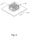
- FIG. 4 is a perspective view of the apparatus shown in FIGS. 1 and 2 after the apparatus has been disposed over the board-mounted electrical component;
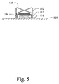
- FIG. 5 is a cross-sectional view of the apparatus shown in FIG. 4 taken along the line 5 - 5 in FIG. 4 ;
- FIG. 6 is a perspective of the heat sink shown in FIG. 1 ;
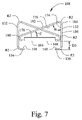
- FIG. 7 is a front elevation view of the heat sink shown in FIG. 6 ;
- FIG. 8 is a side elevation view of the heat sink shown in FIG. 6 ;
- FIG. 9 is a top plan view of the heat sink shown in FIG. 6 ;
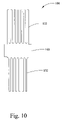
- FIG. 10 is a plan view of a blank that can be used to make the heat sink fingers shown in FIG. 6 before forming or bending the fingers;
- FIG. 11 is a perspective view of the fence shown in FIG. 1 ;
- FIG. 11A is a partial view of a fence having fingers with upwardly bent or formed end portions according to exemplary embodiments
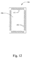
- FIG. 12 is a top elevation view of the fence shown in FIG. 11 ;
- FIGS. 13A and 13B are respective right and left side elevation views of the fence shown in FIG. 11 ;
- FIG. 14 is a front elevation view of the fence shown in FIG. 11 ;
- FIG. 15 is a plan view of a blank that can be used to make the fence shown in FIG. 11 before forming or bending the walls;
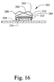
- FIG. 16 is a cross-sectional view of an apparatus capable of providing board level EMI shielding and dissipating heat according to another exemplary embodiment and illustrating the apparatus disposed over a board-mounted electrical component;
- FIG. 17 is a lower perspective view of an apparatus capable of providing board level EMI shielding and dissipating heat according to another exemplary embodiment and illustrating the apparatus disposed over an electrical component mounted to a board where the board includes openings engagingly receiving fingers of the heat sink.
- exemplary embodiments are provided of assemblies capable of providing board level EMI shielding and heat dissipation for one or more electrical components of a board.
- Other aspects relate to components (e.g., fences, heat sinks, etc.) of combined EMI shielding and thermal management assemblies.
- Further aspects relate to methods of using combined EMI shielding and thermal management assemblies.
- Additional aspects relate to methods of making combined EMI shielding and thermal management assemblies, and methods of making the components thereof. Any of these aspects can be used individually or in combination with any one or more of the other aspects.
- the apparatus generally includes a board level EMI shielding fence or frame for electrically grounding the apparatus to a board, such as a printed circuit board, etc.
- the apparatus also includes a structure for dissipating heat generated by the one or more electrical components of the board.
- the heat dissipation structure can also be generally referred to herein as a heat sink or heat spreader.
- the heat sink can cooperate with the fence to provide EMI shielding and thermal management (e.g., heat dissipation and cooling) for the electrical component(s) or package over which the apparatus is disposed.
- a thermal interface (e.g., a thermal interface material, a pad of thermally-conductive material, etc.) can be disposed generally between the heat sink and the electrical component(s) for forming a thermally-conducting heat path from the electrical component(s) to the heat sink, thereby facilitating the transfer of heat generated by the electrical component(s) to the heat sink.
- a thermal interface material e.g., a thermal interface material, a pad of thermally-conductive material, etc.
- a fence includes one or more resilient or spring fingers for making contact with the heat sink.
- the fence may also or alternatively include other means (e.g., EMI gasket materials, etc.) for contacting the heat sink.
- the fence may also include perimeter walls having mounting feet for contacting one or more traces of a board to establish or provide for electrical contact with the board.
- the fence perimeter walls can also include notches or other openings configured for engagingly receiving resilient fingers from the heat sink. Engagement of the heat sink's fingers within the fence's notches can generate a mechanical or clamping force for low thermal impedance and good positive thermal contact as the apparatus is compressed generally towards the top of the fence. Engagement of the heat sink's fingers within the notches can help retain contact between the heat sink and a thermal interface.
- a heat sink is configured for contacting both a fence and a thermal interface.
- the thermal interface can be configured such that the thermal interface is compressed against the one or more electrical components when the heat sink's fingers are engaged with openings of the fence or the board. This compression can help to create sufficient contact between the heat sink, thermal interface, and electrical component(s) for forming a good thermally-conducting heat path from the one or more electrical components to the heat sink, thereby providing the apparatus with good heat dissipation capacity.
- the heat sink is made from sheet metal and has relatively long fingers.
- the relatively long fingers can provide relatively large heat dissipation or cooling surfaces.
- the fingers can also provide sufficient biasing or spring pressure for causing the heat sink to contact and compress the thermal interface against the electrical component(s). That is, the fingers (with their end portions engaged within notches of the fence perimeter walls or openings in the board, etc.) can apply suitable biasing or pressure for maintaining good thermal contact between the heat sink, thermal interface and electrical component(s).
- the biasing applied by the heat sink's fingers can also help the heat sink maintain good thermal and/or electrical contact with the fence.
- the biasing force applied by the heat sink's fingers can firmly hold the heat sink down against the fence. This, in turn, can help reduce any gaps between the fence and the heat sink, thereby inhibiting electromagnetic energy from passing through or leaking out through the interface between the heat sink and the fence.
- FIGS. 1 through 5 illustrate an exemplary combined EMI shielding and thermal management apparatus 100 embodying one or more aspects of the present disclosure.
- the apparatus 100 generally includes a fence 104 , a heat sink 108 , and a thermal interface 112 .
- FIGS. 4 and 5 illustrate the apparatus 100 disposed over an electrical component or electronics package 116 , which, in turn, is surface-mounted to (or otherwise supported by) the board 120 .
- the apparatus 100 can provide EMI shielding for the electrical component 116 and remove or dissipate heat generated by the electrical component 116 .
- the apparatus 100 can shield the electrical component 116 from other EMI emitted from other electrical or electronic components and/or prevent EMI emitted by the electrical component 116 from interfering with other components.
- the apparatus 100 can be used with a wide range of electrical or electronic components and packages mounted on a printed circuit board, such as surface mounted integrated circuits, microprocessors, resistors, and power transistors, by way of example.
- FIGS. 11 through 14 illustrate an exemplary embodiment of the frame or fence 104 , which can be used in the combined EMI shielding and thermal management apparatus 100 .
- the fence 104 generally includes peripheral walls 124 . While the illustrated fence 104 includes four peripheral walls 124 in a generally rectangular configuration, other embodiments can include a fence having more or less than four peripheral walls and/or peripheral walls in a non-rectangular configuration (e.g., triangular, hexagonal, circular, etc.) that conform to the component topography of the PCB or other application in which the apparatus 100 will be used.
- a non-rectangular configuration e.g., triangular, hexagonal, circular, etc.
- each fence wall 124 includes openings or notches 128 for engaging or interlocking with corresponding fingers 132 of the heat sink 108 , as described in more detail herein.
- fence walls 124 include generally rectangular openings or notches 128 .
- Notches 128 A are alternately opposing notches associated with opposing side walls.
- Notches 128 B are opposing notches associated with opposing end walls.
- Alternative embodiments can include more or less notches (and in some cases no openings) in the fence walls 124 . Plus, each fence wall 124 does not need to include the same number of notches, or each fence wall 124 may include the same number of notches.
- one or more of the fence walls 124 may include other types of openings for engaging the heat sink fingers 132 , such as non-rectangular shaped openings, oblong openings, slots, through-holes, etc.
- the fence wall openings can be closed through-hole structures in fence walls 124 of varying geometric shapes that are engaged by heat-sink finger end portions that conform in shape to the geometric cross-sections of the through holes, thereby providing a locking engagement of the heat sink finger end portions to the fence wall through-holes.
- Such heat sink finger engaging end portions may also include added EMI shielding or gasket materials capable of providing increased EMI shielding (for example, at higher frequencies) when engaged to fence wall through-holes.
- the heat sink 108 and fingers 132 are configured (e.g., shaped, sized, spaced, etc.) such that the fingers 132 can be slid over the fence walls 124 to engage the notches or openings 128 of the fence walls 124 .
- the fingers 132 are configured such that the fingers 132 may flex outwardly and/or the fence walls 124 may flex inwardly as the finger end portions 136 are slid over the fence walls 124 for engaging the openings 128 .
- the fence 104 also includes mounting feet 144 for contacting one or more components of the board 120 to provide for electrical contact with the board 120 .
- each fence wall 124 includes mounting feet 144 , which may be integrally formed with the corresponding fence wall 124 .
- the walls 124 include alternately opposing mounting feet 144 with the notches 128 disposed between corresponding pairs of mounting feet 144 .
- the mounting feet 144 can provide mounting surfaces for mating with a ground plane or trace pads of a printed circuit board, and the feet 144 can be dimensioned to selectively mate with specific trade pad locations and dimensions.
- the fence 104 may be made of a material suitable for soldering the feet 144 to trace pads of a printed circuit board.
- Exemplary materials for the fence 104 include cold rolled steel, nickel-silver alloy, or the like.
- Alternative materials for the fence 104 include carbon steel, stainless steel, tin-plated cold rolled steel, etc.
- the fence 104 may also be affixed or mounted to a board by any suitable manner, such as adhesives, mechanical fasteners, clips, etc.
- the fence 104 may be attached to a printed circuit board via soldering the mounting feet 144 to grounded traces positioned on the PCB substrate and/or around the electrical circuits generating (or requiring protection from) EMI as well as around the electrical circuits that are susceptible to EMI.
- the fence 104 also includes resilient or spring fingers 152 .
- the fingers 152 comprise inwardly projecting triangular-shaped extensions disposed along the fence interior perimeter.
- the fence fingers 152 are configured for making contact with the heat sink 108 .
- the fence walls 124 define an opening or window 156 disposed along the upper portion of the fence 104 and about which the fingers 152 are generally disposed.
- each fence finger 152 can include upwardly bent or formed end portions 160 ( FIG. 11A ) configured to help make reliable contact between the fence 104 and the underside 164 of the heat sink 108 .
- each fence finger 152 has an end portion 160 that is bent upwardly at an angle D of about thirty degrees.
- the end portions 160 can preferably be configured such that they extend above the top edges of the fence walls 124 .
- the fence 104 may have one or more fence fingers 152 having end portions bent upwardly at angles more or less than thirty degrees. Further embodiments can include a fence 104 with one or more fence fingers 152 having end portions bent upwardly at different or varying angles.
- the fence fingers 152 may include raised portions, bumps, and/or protuberances disposed at about the free end portions of the fence fingers 152 for contacting the heat sink 108 .
- these raised portions, bumps, and/or protuberances may be integral to the fence fingers 152 , or they may be discrete components that are attached (e.g., welded, adhered, etc.) to the fence fingers 152 .
- the fence fingers 152 do not include any such bent portions, raised portions, bumps, and/or protuberances for contacting the heat sink 108 .
- the fence fingers 152 may also have sufficient resiliency or springiness for allowing the fence fingers 152 to move (e.g., downward in FIGS. 4 and 5 ) and to respond with a sufficient restorative force for making and maintaining good contact between the fence fingers 152 and the underside 164 of the heat sink lid portion or member 168 .
- the fence fingers 152 can help to establish good contact with the heat sink 108 when the heat sink 108 is engaged to the fence 104 via the engagement of the heat sink fingers 132 with the fence notches 128 .
- the contact established between the fence 104 and heat sink 108 can help form an electrically-conductive pathway that provides an effective amount of electrical conduction between the fence 104 and heat sink 108 for conducting electromagnetic energy absorbed by the apparatus 100 through the fence mounting feet 144 to a ground plane of the board 120 .
- Alternative embodiments can include fences having other means for contacting a heat sink.
- another embodiment can include additional materials (e.g., EMI gasket materials etc.) instead of, or in addition to, fence fingers 152 .
- the contact established between the fence 104 and the heat sink 108 can provide an effective amount of electrical conduction for conducting electromagnetic energy absorbed by the apparatus 100 to a ground plane on the board 120 .
- the fence notches 128 and the heat sink fingers 132 can also be relatively configured (e.g., sized, shaped, etc.) such that the lower surfaces 148 of the fingers 132 are generally aligned with the bottom edges of the fence walls 124 . This, in turn, can inhibit electromagnetic energy from passing through or leaking out of gaps or interfaces, thus providing better shielding when the fence 104 is disposed over the electrical component 116 of the board 120 .
- the fence 104 can be integrally or monolithically formed as a single component.
- FIG. 15 illustrates an exemplary blank that can be used for making the fence 104 .
- the fence 104 can be formed by stamping a flat profile pattern in a piece of material for the fence 104 .
- the stamped profile for the fence 104 includes peripheral walls 124 having the mounting feet 144 , notches 128 , and the fingers 152 . After stamping the flat pattern profile for the fence 104 in the piece of material, the walls 124 may then be folded or bent generally perpendicular as shown in FIGS. 11 through 14 . Even though the fence 104 can be formed integrally in this example, such is not required for all embodiments.
- embodiments may include the fence fingers 152 and/or protuberances thereon being discrete components that are separately engaged to the fence 104 , for example, by welding, among other suitable methods.
- Alternative configurations e.g., shapes, sizes, etc.
- materials, and manufacturing methods can be used for making the fence 104 .
- other embodiments can include fences manufactured by drawing. Depending on the particular application, a drawn fence with closed corners may be preferable to other types of fences having non-closed or open corners.
- a wide range of materials can be used for the fence 104 , such as cold rolled steel, stainless steel, nickel-silver alloy, tin-plated cold rolled steel, tin plated copper alloy, carbon steel, brass, copper, aluminum, copper beryllium alloy, phosphor bronze, steel, combinations thereof, other suitable electrically conductive and/or non-magnetic materials.
- a fence 104 is formed from a sheet of non-heat treated material (e.g., tin-plated copper alloy, etc.) having a thickness between about 0.008 inch to about 0.010 inch, a length of about 1.949 inches, and a width of about 1.449 inches.
- the fence 104 can be formed such that the notches 128 along the shorter fence walls 128 have a height of about 0.020 inch, while the notches 128 along the longer fence walls 128 have a height of about 0.039 inch.
- the resulting fence 104 can have a length of about 1.50 inches, a width of about 1.00 inch, and a height of about 0.236 inch.
- the angle A formed between adjacent fence fingers 152 can be about twenty degrees, the distance D can be about 0.025 inch, and the radius of curvature R between adjacent fingers can be about 0.010 inch.
- the fence fingers 152 can have protuberances at the finger free-end portions, where the protuberances have a height of about 0.006 inch relative to the top surfaces of the fingers 152 .
- the dimensions provided in this paragraph are for purposes of illustration only, as the dimensions and materials used for a particular fence can be varied and modified, based on the size of the component(s) to be shielded, space considerations within the overall apparatus, and other factors.
- FIGS. 6 through 9 illustrate an exemplary heat sink 108 that can be used in the combined EMI shielding and thermal management apparatus 100 .
- the heat sink 108 generally includes the lid portion or member 168 and fingers 132 .
- the end portions 136 of the fingers 132 are configured for engaging the fence's notches 128 (or other suitable openings in a fence or board).
- the engagement portions 136 can include inward extensions having generally curved, bent, U-shaped, or L-shaped transverse profiles.
- the heat sink fingers 132 may be biased inwardly toward the corresponding fence wall 124 .
- the flexible tension grip of the heat sink fingers 132 onto the fence walls 124 can help provide relatively good thermal and electrically-conductive contact therebetween. While the illustrated embodiment shows the end portions 136 with generally curved or bent L-shaped transverse profiles, other cross-sectional shapes (e.g., U-shaped, etc.) are also possible depending, for example, on the particular application in which the apparatus 100 will be used.
- the upper portions 133 of the fingers 132 can operate as cooling surfaces or fins for transferring heat from the heat sink 108 to the surrounding environment.
- the heat sink 108 can also be formed from a material having sufficient resiliency or springiness to permit outward movement of the fingers 132 for allowing the fingers 132 to slide generally over the fence walls 124 , and then to respond with a sufficient restorative force (after the finger end portions 136 pass the upper edges 129 of the notches 128 ) for securely engaging the notches 128 and for making/maintaining good contact between the fingers 132 and the fence walls 124 .
- the resilient engagement of the finger end portions 136 with the notches 128 can flex, deflect and/or deform the fingers 132 such that a clamping force is applied generally between the heat sink fingers 132 and the fence 104 .
- the resiliency or springiness of the heat sink fingers 132 and their engagement within the fence notches 128 can apply a clamping force for biasing the generally horizontal heat sink lid portion or member 168 downward relative to the thermal interface 112 (or, in some embodiments, directly onto the electrical component 116 if no thermal interface is used).
- This biasing pressure can help hold the heat sink member 168 down firmly against the thermal interface 112 and/or compress the thermal interface 112 against the electrical component 116 .
- This can help retain good thermal contact between the heat sink 108 , thermal interface 112 , and electrical component 116 .
- the engagement of the fingers 132 with the notches 128 can help create and maintain sufficient contact for providing the apparatus with low thermal impedance and good heat dissipation capacity.
- the biasing force applied by the heat sink fingers 132 can also help maintain good thermal and/or electrical contact between the heat sink underside 164 and the fence fingers 152 .
- the biasing force can help hold the heat sink 108 down firmly against the fence 104 . This, in turn, can help reduce any gaps between the fence 104 and the heat sink 108 , thereby inhibiting electromagnetic energy from passing through or leaking out through the interface between the heat sink 108 and the fence 104 , and/or through the window 156 of the fence 104 .
- the inner lower surfaces 148 of the finger engagement members 136 can also be configured (e.g., curved, etc.) to operate as camming surfaces.
- the heat sink 108 is being relatively moved onto the fence 104 , contact between the curved inner lower surfaces 148 of the heat sink fingers 132 and the fence 104 can urge the heat sink fingers 132 generally outwards. This, in turn, can allow the finger end portions 136 to slide generally over the fence walls 124 . After the finger end portions 136 clear the top edges 129 of the notches 128 , the heat sink fingers 132 and their end portions 136 may then spring generally inwardly to thereby engage or interlock with the notches 128 .
- the heat sink 108 can be integrally or monolithically formed as a single component.
- FIG. 10 illustrates an exemplary blank that can be used for making the heat sink 108 .
- the heat sink 108 can be formed by stamping a profile flat pattern for the heat sink 108 in a piece of material.
- the stamped profile for the heat sink 108 includes the lid portion or member 168 and fingers 132 extending outwardly therefrom. After stamping the flat pattern profile for the heat sink 108 in the piece of material, the fingers 132 may then be folded or bent to the configuration shown in FIGS. 6 through 9 .
- the heat sink 108 can be formed integrally in this example, such is not required for all embodiments.
- heat sink fingers 132 being discrete components that are separately engaged to the generally flat heat sink member 168 , for example, by welding, among other suitable methods.
- Alternative configurations e.g., shapes, sizes, etc.
- manufacturing methods can be used for making the heat sink 108 .
- the heat sink 108 can be formed from a wide variety of materials, which are preferably good thermally conducting and EMI shielding materials.
- the heat sink 108 is also formed of a resilient material.
- Exemplary materials from which the heat sink 108 can be formed include beryllium copper alloys, aluminum, brass, phosphor bronze, etc.
- the heat sink 108 may comprise bare or uncoated metal.
- the heat sink 108 may comprise a metal coated with a suitable electrically-conductive plating to provide galvanic compatibility with the fence 104 .
- the heat sink 108 (or at least its heat sink fingers 132 ) is made of a springy material such that the fingers can snap into the openings of the fence walls, thereby providing sufficient force between the fence and the heat sink for enhancing thermal contact between the heat sink 108 and the thermal interface 112 .
- the heat sink 108 is formed from a sheet of brass (which may be tin-plated) having a thickness of about 0.032 inch.
- the heat sink 108 can be formed such that the angle B formed between the each heat sink finger's generally vertical portion 174 and angled portion 176 is about seventy degrees.
- the angle C formed between each heat sink finger's slanted portion 176 and the upper surface 178 of the heat sink member 168 can be about twenty degrees.
- Each heat sink finger 132 can also have radii of curvature R 2 of about 0.050 inch, and a width W of about 0.085 inch.
- the gap or spaced distance D 2 as shown in FIG. 8 between adjacent fingers 132 can be about 0.020 inch.
- the gap or spaced distance D 3 between the finger engagement members 136 and the lower surface 164 of the heat sink member 168 can be about 0.021 inch.
- the dimensions provided in this paragraph are for purposes of illustration only, as the dimensions and materials used for a particular heat sink can be varied and modified, based on the size of the component to be shielded, space considerations within the overall apparatus, and other factors.
- other embodiments can include heat sink fingers with different radii of curvature such that each curved portion of a heat sink finger does not have the same radius of curvature.
- each heat sink finger 132 includes a first curved portion 180 extending from the generally horizontal member 168 , a second slanted portion 182 extending from the first curved portion 180 and disposed above the generally horizontal member 168 , a third curved portion 184 extending from the second slanted portion 182 , a fourth generally vertical portion 186 extending from the third curved portion 184 , and the engagement portion 136 extending from the fourth generally vertical portion 184 .
- each finger 132 includes a generally triangular profile.
- Alternative embodiments can include more or less heat sink fingers 132 and/or one or more heat sink fingers 132 having different configurations (e.g., shaped, sized, etc.) than what is shown in the figures.
- FIG. 16 illustrates another embodiment of a combined EMI shielding and thermal management apparatus 200 .
- the heat sink fingers 232 of the heat sink 208 have a generally quadrilateral shape within a generally triangular profile.
- the profile of the heat sink fingers 232 includes a fourth side 283 formed by truncating sides 282 and 284 , thereby producing heat sink fingers having a lower overall height relative to the upper surface of the board
- the apparatus 200 also includes a fence 204 and a thermal interface 212 disposed between the heat sink 208 and electronic component 216 .
- Various embodiments can thus provide a relatively simple-to-construct fence and heat sink, where the heat sink can be snapped onto the fence or the board.
- the heat sink can include a contact surface area to draw heat from an electrical component and cooling fins for transferring such heat to the surrounding environment.
- the apparatus 100 includes the thermal interface 112 disposed between the heat sink 108 and electrical component 116 .
- the thermal interface 112 can comprise one or more separate layers disposed on the electrical component 116 and/or one or more separate layers disposed on the lower surface 164 of the heat sink member 168 .
- the thermal interface 112 preferably has a thickness no larger than the gap between top of fence 104 and the top of the electrical component 116 .
- thermal interface 112 A wide variety of materials can be used for the thermal interface 112 .
- various embodiments can include a thermal interface formed from ceramic particles, ferrite EMI/RFI absorbing particles, metal or fiberglass meshes in a base of rubber, gel, grease or wax, etc.
- Alternative embodiments can provide an apparatus that does not include a separate thermal interface 112 .
- the heat sink can make direct physical contact with and abut the electrical component or package over which the apparatus is disposed.
- EMI gasket material or other suitable gap fillers may be disposed generally between the heat sink fingers and the fence, such as for shielding applications with frequencies above five hundred megahertz.
- other embodiments do not include such EMI gasket material or gap fillers between the heat sink fingers and the fence.
- the apparatus 100 can be shipped or delivered with the thermal interface 112 disposed on the heat sink 108 .
- the fence 104 can then be mounted to the board 120 such that the fence 104 is disposed generally around the electrical component 116 .
- the mounting feet 144 of the fence 104 can be soldered to traces of the board 120 .
- the heat sink 108 (with the thermal interface 112 thereon) can be snapped into the working position such that heat sink fingers 132 are engaged with the fence's notches 128 .
- the heat sink 108 can be relatively moved towards the fence 104 such that the lower surfaces 148 of the heat sink fingers 132 contact the fence 104 .
- continued relative movement of the heat sink 108 onto the fence 104 allows the lower surfaces 148 to operate as camming surfaces for urging the fingers 132 to move generally outward.
- the heat sink finger end portions 136 can slide generally over the fence walls 124 . After the heat sink finger end portions 136 clear the upper edges 129 of the fence notches 128 , the heat sink finger end portions 136 may spring generally inwardly thereby engaging or interlocking with the fence notches 128 .
- the resiliency or springiness of the heat sink fingers 132 can apply a biasing pressure forcing the heat sink member 108 downward onto the thermal interface 112 (or, in some embodiments, directly onto the electronic component if no thermal interface is used).
- This biasing pressure can help hold the heat sink member 168 down firmly against the thermal interface 112 and/or compress the thermal interface 112 against the electrical component 116 .
- This can help retain good thermal contact between the heat sink 108 , thermal interface 112 , and electrical component 116 .
- the engagement of the fingers 132 with the notches 128 can help create and maintain sufficient contact for providing the apparatus with low thermal impedance and good heat dissipation capacity.
- the heat sink's underside 164 can make contact with the fence fingers 152 .
- continued relative movement of the heat sink 108 onto the fence 104 can urge and cause downward movement of the fence fingers 152 .
- the fence fingers 152 have sufficient resiliency or springiness to permit the downward movement of the fence fingers 152 and also cause the fence fingers 152 to respond with a sufficient restorative force for making and maintaining good contact between the fence fingers 152 and the heat sink underside 164 .
- the fence fingers 152 can help to establish good contact with the heat sink 108 .
- the biasing force applied by the heat sink fingers 132 can also help maintain good thermal and/or electrical contact between the heat sink underside 164 and the fence fingers 152 .
- the biasing force applied by the heat sink fingers 132 can help hold the heat sink underside 164 down firmly against the fence 104 . This, in turn, can help reduce any gaps between the fence 104 and the heat sink 108 , thereby inhibiting electromagnetic energy from passing through or leaking out through the interface between the heat sink 108 and the fence 104 , and/or through the window 156 of the fence 104 .
- contact established between the fence 104 and heat sink 108 can help form an electrically-conductive pathway for conducting electromagnetic energy absorbed by the apparatus 100 through the fence mounting feet 144 to a ground plane via the board 120 .
- FIG. 17 illustrates another embodiment of a combined EMI shielding and thermal management apparatus 300 embodying one or more aspects of the present disclosure.
- the heat sink fingers 332 of the heat sink 308 are positioned through openings 327 in the board 320 such that the end portions 336 of the heat sink fingers 332 are engaged with a lower surface 321 of the board 320 .
- the apparatus 300 may also be used with boards that do not have any such openings 327 .
- the fingers can be configured to be positioned generally around and under the board (instead of through openings) to engage the board's underside.
- the end portions of the fingers may be engagingly received within openings or notches defined by the fence.
- various embodiments can thus allow cost savings to a customer/manufacturer. This is because a customer/manufacturer can purchase a combined EMI shielding and thermal management apparatus (e.g., as a kit, etc.) instead of purchasing separate apparatus to respectively provide EMI shielding and to provide thermal management.
- a customer/manufacturer can purchase a combined EMI shielding and thermal management apparatus (e.g., as a kit, etc.) instead of purchasing separate apparatus to respectively provide EMI shielding and to provide thermal management.
- the articles “a”, “an”, “the” and “said” are intended to mean that there are one or more of such elements or features.
- the terms “comprising”, “including” and “having” are intended to be inclusive and mean that there may be additional elements or features other than those specifically noted. It is further to be understood that the methods “steps”, “processes”, and “operations” thereof described herein are not to be construed as necessarily requiring their performance in the particular order discussed or illustrated, unless specifically identified as an order or performance. It is also to be understood that additional or alternative steps may be employed.
Landscapes
- Shielding Devices Or Components To Electric Or Magnetic Fields (AREA)
- Cooling Or The Like Of Electrical Apparatus (AREA)
Abstract
Description
Claims (16)
Priority Applications (2)
| Application Number | Priority Date | Filing Date | Title |
|---|---|---|---|
| US11/415,460 US7317618B2 (en) | 2006-03-09 | 2006-05-01 | Combined board level shielding and thermal management |
| PCT/US2007/063077 WO2007103733A2 (en) | 2006-03-09 | 2007-03-01 | Combined board level shielding and thermal management |
Applications Claiming Priority (2)
| Application Number | Priority Date | Filing Date | Title |
|---|---|---|---|
| US78079506P | 2006-03-09 | 2006-03-09 | |
| US11/415,460 US7317618B2 (en) | 2006-03-09 | 2006-05-01 | Combined board level shielding and thermal management |
Publications (2)
| Publication Number | Publication Date |
|---|---|
| US20070211436A1 US20070211436A1 (en) | 2007-09-13 |
| US7317618B2 true US7317618B2 (en) | 2008-01-08 |
Family
ID=38475686
Family Applications (1)
| Application Number | Title | Priority Date | Filing Date |
|---|---|---|---|
| US11/415,460 Active 2026-06-14 US7317618B2 (en) | 2006-03-09 | 2006-05-01 | Combined board level shielding and thermal management |
Country Status (2)
| Country | Link |
|---|---|
| US (1) | US7317618B2 (en) |
| WO (1) | WO2007103733A2 (en) |
Cited By (15)
| Publication number | Priority date | Publication date | Assignee | Title |
|---|---|---|---|---|
| US20090002949A1 (en) * | 2007-06-29 | 2009-01-01 | Lucent Technologies Inc. | Heat transfer for electronic component via an electromagnetic interference (emi) shield having shield deformation |
| US20100144410A1 (en) * | 2007-01-29 | 2010-06-10 | Takeshi Ishihara | Shielding structure and member for electronic device and electronic device including the same |
| US7965514B2 (en) | 2009-06-05 | 2011-06-21 | Laird Technologies, Inc. | Assemblies and methods for dissipating heat from handheld electronic devices |
| US20120045908A1 (en) * | 2010-08-20 | 2012-02-23 | Hon Hai Precision Industry Co., Ltd. | Electrical connector having metallic cage shrouding emi from passive device from cpu |
| US20120140432A1 (en) * | 2010-12-01 | 2012-06-07 | Nxp B.V. | Radio frequency circuit with impedance matching |
| US8477499B2 (en) | 2009-06-05 | 2013-07-02 | Laird Technologies, Inc. | Assemblies and methods for dissipating heat from handheld electronic devices |
| US8890003B2 (en) | 2013-01-03 | 2014-11-18 | International Business Machines Corporation | Multiple-layered electromagnetic shielding |
| US9010405B1 (en) * | 2011-02-07 | 2015-04-21 | U.S. Department Of Energy | Fluid-cooled heat sink with improved fin areas and efficiencies for use in cooling various devices |
| US9788413B2 (en) | 2015-11-09 | 2017-10-10 | Motorola Solutions, Inc. | Electromagnetic interference shielding assembly and method of providing electromagnetic interference shielding |
| US10123466B2 (en) | 2017-03-31 | 2018-11-06 | Raytheon Company | Electrically and thermally conductive planar interface gasket with deformable fingers |
| US10477739B2 (en) | 2015-10-16 | 2019-11-12 | Laird Technologies, Inc. | Thermally-conductive electromagnetic interference (EMI) absorbers positioned or positionable between board level shields and heat sinks |
| US10687447B2 (en) | 2016-10-14 | 2020-06-16 | Laird Technologies, Inc. | Methods of applying thermal interface materials to board level shields |
| US11229147B2 (en) | 2015-02-06 | 2022-01-18 | Laird Technologies, Inc. | Thermally-conductive electromagnetic interference (EMI) absorbers with silicon carbide |
| US11579668B2 (en) | 2020-09-24 | 2023-02-14 | Hewlett Packard Enterprise Development Lp | Multipoint contact conduction cooling of a removable device |
| US11659689B2 (en) | 2018-02-19 | 2023-05-23 | Interdigital Madison Patent Holdings, Sas | Heatsink assembly for an electronic device |
Families Citing this family (61)
| Publication number | Priority date | Publication date | Assignee | Title |
|---|---|---|---|---|
| US8279624B2 (en) | 2010-06-03 | 2012-10-02 | Laird Technologies, Inc. | Board level electromagnetic interference (EMI) shields with through hole latching mechanisms |
| CN102906870A (en) * | 2010-06-18 | 2013-01-30 | 夏普株式会社 | Heat dissipation structure of electronic equipment |
| RU2474056C1 (en) * | 2011-09-05 | 2013-01-27 | Открытое акционерное общество научно-внедренческое предприятие "ПРОТЕК" | Radio interference module |
| WO2013095490A1 (en) * | 2011-12-22 | 2013-06-27 | Hewlett-Packard Development Company, L.P. | Heat sink base and shield |
| US9048124B2 (en) * | 2012-09-20 | 2015-06-02 | Apple Inc. | Heat sinking and electromagnetic shielding structures |
| US9470720B2 (en) | 2013-03-08 | 2016-10-18 | Sandisk Technologies Llc | Test system with localized heating and method of manufacture thereof |
| US9603292B2 (en) * | 2013-03-15 | 2017-03-21 | A.K. Stamping Company, Inc. | Aluminum EMI/RF shield with fins |
| US9538693B2 (en) * | 2013-03-15 | 2017-01-03 | A.K. Stamping Company, Inc. | Aluminum EMI / RF shield |
| CN103237412B (en) * | 2013-03-27 | 2016-03-23 | 苏州远创达科技有限公司 | A kind of soft copy mounting structure and manufacture method, soft copy product |
| US9313874B2 (en) * | 2013-06-19 | 2016-04-12 | SMART Storage Systems, Inc. | Electronic system with heat extraction and method of manufacture thereof |
| US9898056B2 (en) | 2013-06-19 | 2018-02-20 | Sandisk Technologies Llc | Electronic assembly with thermal channel and method of manufacture thereof |
| US10013033B2 (en) | 2013-06-19 | 2018-07-03 | Sandisk Technologies Llc | Electronic assembly with thermal channel and method of manufacture thereof |
| US9158349B2 (en) | 2013-10-04 | 2015-10-13 | Sandisk Enterprise Ip Llc | System and method for heat dissipation |
| US20150201486A1 (en) * | 2014-01-16 | 2015-07-16 | Whelen Engineering Company, Inc. | Stacked Heatsink Assembly |
| US9549457B2 (en) | 2014-02-12 | 2017-01-17 | Sandisk Technologies Llc | System and method for redirecting airflow across an electronic assembly |
| US9497889B2 (en) | 2014-02-27 | 2016-11-15 | Sandisk Technologies Llc | Heat dissipation for substrate assemblies |
| US9348377B2 (en) | 2014-03-14 | 2016-05-24 | Sandisk Enterprise Ip Llc | Thermal isolation techniques |
| US9485851B2 (en) | 2014-03-14 | 2016-11-01 | Sandisk Technologies Llc | Thermal tube assembly structures |
| US9519319B2 (en) | 2014-03-14 | 2016-12-13 | Sandisk Technologies Llc | Self-supporting thermal tube structure for electronic assemblies |
| KR102286337B1 (en) * | 2014-10-17 | 2021-08-04 | 쓰리엠 이노베이티브 프로퍼티즈 컴파니 | Emi shielding structure and thermal pad, and electronic circuit board assembly including the same |
| DE102015001148B4 (en) * | 2015-01-30 | 2019-04-11 | e.solutions GmbH | Arrangement and method for electromagnetic shielding |
| US9560737B2 (en) | 2015-03-04 | 2017-01-31 | International Business Machines Corporation | Electronic package with heat transfer element(s) |
| JP5949988B1 (en) * | 2015-03-20 | 2016-07-13 | 日本電気株式会社 | Electronic equipment |
| US10426037B2 (en) | 2015-07-15 | 2019-09-24 | International Business Machines Corporation | Circuitized structure with 3-dimensional configuration |
| US9781819B2 (en) * | 2015-07-31 | 2017-10-03 | Laird Technologies, Inc. | Multifunctional components for electronic devices and related methods of providing thermal management and board level shielding |
| US10175064B2 (en) | 2015-09-25 | 2019-01-08 | International Business Machines Corporation | Circuit boards and electronic packages with embedded tamper-respondent sensor |
| US9578764B1 (en) | 2015-09-25 | 2017-02-21 | International Business Machines Corporation | Enclosure with inner tamper-respondent sensor(s) and physical security element(s) |
| US10172239B2 (en) | 2015-09-25 | 2019-01-01 | International Business Machines Corporation | Tamper-respondent sensors with formed flexible layer(s) |
| US9894749B2 (en) | 2015-09-25 | 2018-02-13 | International Business Machines Corporation | Tamper-respondent assemblies with bond protection |
| US9911012B2 (en) | 2015-09-25 | 2018-03-06 | International Business Machines Corporation | Overlapping, discrete tamper-respondent sensors |
| US9924591B2 (en) | 2015-09-25 | 2018-03-20 | International Business Machines Corporation | Tamper-respondent assemblies |
| US10098235B2 (en) | 2015-09-25 | 2018-10-09 | International Business Machines Corporation | Tamper-respondent assemblies with region(s) of increased susceptibility to damage |
| US9591776B1 (en) | 2015-09-25 | 2017-03-07 | International Business Machines Corporation | Enclosure with inner tamper-respondent sensor(s) |
| US10143090B2 (en) | 2015-10-19 | 2018-11-27 | International Business Machines Corporation | Circuit layouts of tamper-respondent sensors |
| US9978231B2 (en) | 2015-10-21 | 2018-05-22 | International Business Machines Corporation | Tamper-respondent assembly with protective wrap(s) over tamper-respondent sensor(s) |
| WO2017087136A1 (en) * | 2015-11-20 | 2017-05-26 | Laird Technologies, Inc. | Board level shield including an integrated heat sink |
| US9913389B2 (en) | 2015-12-01 | 2018-03-06 | International Business Corporation Corporation | Tamper-respondent assembly with vent structure |
| US10327343B2 (en) | 2015-12-09 | 2019-06-18 | International Business Machines Corporation | Applying pressure to adhesive using CTE mismatch between components |
| US9555606B1 (en) | 2015-12-09 | 2017-01-31 | International Business Machines Corporation | Applying pressure to adhesive using CTE mismatch between components |
| US9554477B1 (en) | 2015-12-18 | 2017-01-24 | International Business Machines Corporation | Tamper-respondent assemblies with enclosure-to-board protection |
| DE112016005793B4 (en) * | 2015-12-18 | 2023-09-21 | Continental Automotive Systems, Inc. | Sliding thermal shield |
| CN108702862B (en) * | 2016-02-19 | 2021-03-09 | 爱法组装材料公司 | RF shield with selectively integrated solder |
| US9916744B2 (en) | 2016-02-25 | 2018-03-13 | International Business Machines Corporation | Multi-layer stack with embedded tamper-detect protection |
| US10772245B2 (en) * | 2016-04-04 | 2020-09-08 | Commscope Technologies Llc | Systems and methods for thermal management for high power density EMI shielded electronic devices |
| US9904811B2 (en) | 2016-04-27 | 2018-02-27 | International Business Machines Corporation | Tamper-proof electronic packages with two-phase dielectric fluid |
| US9881880B2 (en) | 2016-05-13 | 2018-01-30 | International Business Machines Corporation | Tamper-proof electronic packages with stressed glass component substrate(s) |
| US9913370B2 (en) | 2016-05-13 | 2018-03-06 | International Business Machines Corporation | Tamper-proof electronic packages formed with stressed glass |
| US9858776B1 (en) | 2016-06-28 | 2018-01-02 | International Business Machines Corporation | Tamper-respondent assembly with nonlinearity monitoring |
| US10321589B2 (en) | 2016-09-19 | 2019-06-11 | International Business Machines Corporation | Tamper-respondent assembly with sensor connection adapter |
| US10271424B2 (en) | 2016-09-26 | 2019-04-23 | International Business Machines Corporation | Tamper-respondent assemblies with in situ vent structure(s) |
| US10299372B2 (en) | 2016-09-26 | 2019-05-21 | International Business Machines Corporation | Vented tamper-respondent assemblies |
| US10342167B2 (en) * | 2016-11-01 | 2019-07-02 | Gentex Corporation | Electromagnetic shield for rearview assembly |
| US9999124B2 (en) | 2016-11-02 | 2018-06-12 | International Business Machines Corporation | Tamper-respondent assemblies with trace regions of increased susceptibility to breaking |
| US10238004B2 (en) * | 2016-11-07 | 2019-03-19 | Rockwell Automation Technologies, Inc. | Controller with enhanced thermal properties |
| US10542644B2 (en) | 2016-12-14 | 2020-01-21 | A.K. Stamping Company, Inc. | Two-piece solderable shield |
| US10327329B2 (en) | 2017-02-13 | 2019-06-18 | International Business Machines Corporation | Tamper-respondent assembly with flexible tamper-detect sensor(s) overlying in-situ-formed tamper-detect sensor |
| US10306753B1 (en) | 2018-02-22 | 2019-05-28 | International Business Machines Corporation | Enclosure-to-board interface with tamper-detect circuit(s) |
| US11122682B2 (en) | 2018-04-04 | 2021-09-14 | International Business Machines Corporation | Tamper-respondent sensors with liquid crystal polymer layers |
| KR102553021B1 (en) | 2018-12-18 | 2023-07-07 | 삼성전자주식회사 | Housing for receiving electronic devices and electronic system having the same |
| US11348877B2 (en) * | 2019-12-10 | 2022-05-31 | Starry, Inc. | RF shielding can with integral spring fingers |
| WO2022173887A1 (en) * | 2021-02-12 | 2022-08-18 | Arris Enterprises Llc | Metamaterial heat spreader |
Citations (97)
| Publication number | Priority date | Publication date | Assignee | Title |
|---|---|---|---|---|
| US3047648A (en) | 1959-05-04 | 1962-07-31 | Northrop Corp | Transistor clip, heat sink type |
| US3208511A (en) | 1961-11-21 | 1965-09-28 | Int Electronic Res Corp | Transistor elevated cooler |
| US3572428A (en) | 1969-01-29 | 1971-03-23 | Motorola Inc | Clamping heat sink |
| US3721746A (en) | 1971-10-01 | 1973-03-20 | Motorola Inc | Shielding techniques for r.f. circuitry |
| US4203488A (en) | 1978-03-01 | 1980-05-20 | Aavid Engineering, Inc. | Self-fastened heat sinks |
| US4235285A (en) | 1979-10-29 | 1980-11-25 | Aavid Engineering, Inc. | Self-fastened heat sinks |
| US4345267A (en) | 1980-03-31 | 1982-08-17 | Amp Incorporated | Active device substrate connector having a heat sink |
| US4405961A (en) | 1981-08-06 | 1983-09-20 | International Business Machines | Thermoelectric cooling of magnetic head assemblies |
| US4433886A (en) | 1981-12-17 | 1984-02-28 | Elco Corporation | Connector mounting for integrated circuit chip packages |
| US4481525A (en) | 1982-08-12 | 1984-11-06 | Anthony D. Calabro | Heat dissipator for integrated circuit chips |
| US4508163A (en) | 1983-01-18 | 1985-04-02 | Aavid Engineering, Inc. | Heat sinks for integrated circuit modules |
| US4661888A (en) | 1984-07-03 | 1987-04-28 | Hewlett-Packard Company | Removable modular housing for RF circuits |
| US4679118A (en) | 1984-08-07 | 1987-07-07 | Aavid Engineering, Inc. | Electronic chip-carrier heat sinks |
| US4729426A (en) | 1986-03-06 | 1988-03-08 | Thermalloy Incorporated | Bonded clip heat sink |
| US4754101A (en) | 1986-10-23 | 1988-06-28 | Instrument Specialties Co., Inc. | Electromagnetic shield for printed circuit board |
| US4933746A (en) | 1988-09-12 | 1990-06-12 | Aavid Engineering, Inc. | Three-legged clip |
| US5052481A (en) | 1988-05-26 | 1991-10-01 | International Business Machines Corporation | High conduction cooling module having internal fins and compliant interfaces for vlsi chip technology |
| US5060114A (en) | 1990-06-06 | 1991-10-22 | Zenith Electronics Corporation | Conformable pad with thermally conductive additive for heat dissipation |
| US5130888A (en) | 1984-05-31 | 1992-07-14 | Thermalloy Incorporated | Spring clip fastener for surface mounting of printed circuit board components |
| US5175613A (en) | 1991-01-18 | 1992-12-29 | Digital Equipment Corporation | Package for EMI, ESD, thermal, and mechanical shock protection of circuit chips |
| US5175395A (en) | 1991-11-27 | 1992-12-29 | Rockwell International Corporation | Electromagnetic shield |
| US5208731A (en) | 1992-01-17 | 1993-05-04 | International Electronic Research Corporation | Heat dissipating assembly |
| US5241453A (en) | 1991-11-18 | 1993-08-31 | The Whitaker Corporation | EMI shielding device |
| US5285350A (en) | 1992-08-28 | 1994-02-08 | Aavid Engineering, Inc. | Heat sink plate for multiple semi-conductors |
| US5287001A (en) | 1991-05-03 | 1994-02-15 | International Business Machines Corporation | Cooling structures and package modules for semiconductors |
| US5288313A (en) | 1990-05-31 | 1994-02-22 | Shipley Company Inc. | Electroless plating catalyst |
| US5295043A (en) | 1992-02-03 | 1994-03-15 | Tandon Corporation | Clip-on heat sink and method of cooling a computer chip package |
| US5329426A (en) | 1993-03-22 | 1994-07-12 | Digital Equipment Corporation | Clip-on heat sink |
| US5354951A (en) | 1993-03-15 | 1994-10-11 | Leader Tech, Inc. | Circuit board component shielding enclosure and assembly |
| US5357404A (en) | 1991-11-18 | 1994-10-18 | The Whitaker Corporation | EMI shield, and assembly using same |
| US5365399A (en) | 1992-08-03 | 1994-11-15 | Motorola, Inc. | Heat sinking apparatus for surface mountable power devices |
| US5367433A (en) | 1993-09-27 | 1994-11-22 | Blomquist Michael L | Package clip on heat sink |
| EP0632686A1 (en) | 1993-06-29 | 1995-01-04 | Telefonaktiebolaget Lm Ericsson | A device for shielding and/or cooling electronic components |
| US5416668A (en) | 1993-11-09 | 1995-05-16 | At&T Corp. | Shielded member |
| US5485037A (en) | 1993-04-12 | 1996-01-16 | Amkor Electronics, Inc. | Semiconductor device having a thermal dissipator and electromagnetic shielding |
| US5524908A (en) | 1994-09-14 | 1996-06-11 | W. L. Gore & Associates | Multi-layer EMI/RFI gasket shield |
| US5541811A (en) * | 1994-04-11 | 1996-07-30 | Telefonaktiebolaget Lm Ericsson | Shielding and cooling arrangement |
| US5550713A (en) | 1995-09-06 | 1996-08-27 | Aironet Wireless Communications, Inc. | Electromagnetic shielding assembly for printed circuit board |
| US5552635A (en) | 1994-01-11 | 1996-09-03 | Samsung Electronics Co., Ltd. | High thermal emissive semiconductor device package |
| US5566052A (en) | 1995-06-08 | 1996-10-15 | Northern Telecom Limited | Electronic devices with electromagnetic radiation interference shields and heat sinks |
| US5640047A (en) | 1995-09-25 | 1997-06-17 | Mitsui High-Tec, Inc. | Ball grid assembly type semiconductor device having a heat diffusion function and an electric and magnetic shielding function |
| US5663786A (en) | 1994-09-13 | 1997-09-02 | Noritsu Koki Co., Ltd. | Film charging apparatus for photographic printer |
| US5706579A (en) | 1995-02-06 | 1998-01-13 | Rjr Polymers, Inc. | Method of assembling integrated circuit package |
| US5717248A (en) * | 1994-03-14 | 1998-02-10 | Siemens Nixdorf Informationssysteme Ag | Cooling and screening device having contact pins for an integrated circuit |
| US5717577A (en) | 1996-10-30 | 1998-02-10 | Ericsson, Inc. | Gasketed shield can for shielding emissions of electromagnetic energy |
| US5763824A (en) | 1996-05-08 | 1998-06-09 | W. L. Gore & Associates, Inc. | Lid assembly for shielding electronic components from EMI/RFI interferences |
| US5804875A (en) | 1996-12-10 | 1998-09-08 | Dell Computer Corporation | Computer system with heat sink having an integrated grounding tab |
| US5811050A (en) | 1994-06-06 | 1998-09-22 | Gabower; John F. | Electromagnetic interference shield for electronic devices |
| US5866943A (en) | 1997-06-23 | 1999-02-02 | Lsi Logic Corporation | System and method for forming a grid array device package employing electomagnetic shielding |
| US5893409A (en) | 1995-08-28 | 1999-04-13 | Siemens Aktiengesellschaft | Cooling element for electronic components |
| EP0910005A2 (en) | 1997-10-15 | 1999-04-21 | Hewlett-Packard Company | Thermal dissipation and EMI shielding structure for notebook computers |
| US5917701A (en) | 1997-11-05 | 1999-06-29 | Artesyn Technologies, Inc. | Heat sink hold-down clip |
| US5990418A (en) | 1997-07-29 | 1999-11-23 | International Business Machines Corporation | Hermetic CBGA/CCGA structure with thermal paste cooling |
| US6005186A (en) | 1998-03-27 | 1999-12-21 | International Business Machines Corporation | Snap-fit electromagnetic shield |
| US6025991A (en) | 1998-02-16 | 2000-02-15 | Alps Electric Co., Ltd. | Electronic apparatus having heat dissipating arrangement |
| US6049469A (en) * | 1997-08-20 | 2000-04-11 | Dell Usa, L.P. | Combination electromagnetic shield and heat spreader |
| US6075700A (en) | 1999-02-02 | 2000-06-13 | Compaq Computer Corporation | Method and system for controlling radio frequency radiation in microelectronic packages using heat dissipation structures |
| US6122167A (en) | 1998-06-02 | 2000-09-19 | Dell Usa, L.P. | Integrated hybrid cooling with EMI shielding for a portable computer |
| US6166918A (en) | 1996-08-22 | 2000-12-26 | Telefonaktiebolaget Lm Ericsson | Protective shield for electrical components |
| US6178318B1 (en) | 1997-04-16 | 2001-01-23 | Telefonaktiebolaget L M Ericsson | Shielding housing and a method of producing a shielding housing |
| US6178097B1 (en) | 1999-01-22 | 2001-01-23 | Dial Tool Industries, Inc. | RF shield having removable cover |
| US6181573B1 (en) | 1997-03-19 | 2001-01-30 | Telefonaktiebolaget Lm Ericsson (Publ) | Two-part electromagnetic radiation shielding device for mounting on a printed circuit board |
| US6195267B1 (en) | 1999-06-23 | 2001-02-27 | Ericsson Inc. | Gel structure for combined EMI shielding and thermal control of microelectronic assemblies |
| US6205026B1 (en) | 2000-01-31 | 2001-03-20 | Intel Corporation | Heat sink retention components and system |
| US6208515B1 (en) | 1996-11-26 | 2001-03-27 | Siemens Aktiengesellschaft | Socket for an integrated circuit |
| US6212073B1 (en) | 1998-10-19 | 2001-04-03 | Kitagawa Industries Co., Inc. | Heat sink |
| WO2001041521A1 (en) | 1999-12-01 | 2001-06-07 | Cool Options, Inc. | Thermally conductive electronic device case |
| US6269008B1 (en) | 1999-11-22 | 2001-07-31 | Lucent Technologies Inc. | Multi-walled electromagnetic interference shield |
| US20010046119A1 (en) | 1998-10-30 | 2001-11-29 | Takeshi Hamano | Low profile EMI shield with heat spreading plate |
| US6377475B1 (en) | 2001-02-26 | 2002-04-23 | Gore Enterprise Holdings, Inc. | Removable electromagnetic interference shield |
| US6377472B1 (en) | 2000-04-18 | 2002-04-23 | Hon Hai Precision Ind. Co., Ltd. | Shielding device |
| US6388189B1 (en) | 2000-03-01 | 2002-05-14 | Sony Corporation | Shield case |
| US6410846B1 (en) | 1998-12-15 | 2002-06-25 | Vanguard Products Corporation | Electromagnetic interference shielding device |
| US6430043B1 (en) | 2000-10-30 | 2002-08-06 | Intel Corporation | Heat sink grounding unit |
| US6445583B1 (en) * | 2001-01-26 | 2002-09-03 | Laird Technologies, Inc. | Snap in heat sink shielding lid |
| US6490173B2 (en) | 2000-12-19 | 2002-12-03 | Thomson Licensing, S.A. | Method and apparatus for providing electromagnetic shielding |
| US6501018B2 (en) | 2001-01-31 | 2002-12-31 | Hewlett-Packard Company | EMI gasket having enhanced z-axis compliance |
| US6504095B1 (en) | 1999-11-23 | 2003-01-07 | Telefonaktiebolaget Lm Ericsson (Publ) | Module cover element |
| US6545871B1 (en) * | 2000-10-27 | 2003-04-08 | Thomson Licensing, S.A. | Apparatus for providing heat dissipation for a circuit element |
| US20030066672A1 (en) | 2001-05-10 | 2003-04-10 | Watchko George R. | Thermal-sprayed metallic conformal coatings used as heat spreaders |
| US6552261B2 (en) * | 2001-04-27 | 2003-04-22 | Bmi, Inc. | Push-fit shield |
| US6590783B2 (en) | 2000-05-27 | 2003-07-08 | Mannesmann Vdo Ag | Shielded electronic circuit |
| US6624432B1 (en) | 1999-10-12 | 2003-09-23 | Shielding For Electronics, Inc. | EMI containment apparatus |
| WO2003088729A1 (en) | 2002-04-10 | 2003-10-23 | Gore Enterprise Holdings, Inc. | Board-level emi shield with enhanced thermal dissipation |
| US6673998B1 (en) * | 2003-01-02 | 2004-01-06 | Accton Technology Corporation | Electromagnetic shielding device with heat-dissipating capability |
| US6674653B1 (en) | 1999-04-16 | 2004-01-06 | Agilent Technologies, Inc. | Shielding scheme for a circuit board |
| US6676137B2 (en) | 2002-02-27 | 2004-01-13 | Hewlett-Packard Development Company, L.P. | Snap-on EMI gasket clip and method of sealing a computer chassis from EMI |
| US20040052064A1 (en) * | 2001-11-15 | 2004-03-18 | Oliver Michael J. | Electromagnetic shielding and cooling device for printed circuit board |
| EP1420625A2 (en) * | 2002-11-12 | 2004-05-19 | Thomson Licensing S.A. | Shield casing with heat sink for electric circuit |
| US6943287B2 (en) | 2003-03-31 | 2005-09-13 | Molex Incorporated | Shielding cage with improved EMI shielding gasket construction |
| US6946598B1 (en) | 2003-02-25 | 2005-09-20 | Storage Technology Corporation | Snap-in slot mount RFI/EMI clips |
| US6949706B2 (en) * | 2001-09-28 | 2005-09-27 | Siemens Information And Communication Mobile, Llc | Radio frequency shield for electronic equipment |
| US20050237727A1 (en) | 2004-04-26 | 2005-10-27 | Adc Broadband Access Systems, Inc. | Radio frequency shield covers |
| US20050236171A1 (en) | 2004-04-23 | 2005-10-27 | Garcia Jorge L | Shield frame for a radio frequency shielding assembly |
| US6979773B2 (en) | 2002-07-10 | 2005-12-27 | Siemens Aktiengesellschaft | Screening device for electronic subassemblies on a printed circuit board |
| US6989994B2 (en) | 2004-02-26 | 2006-01-24 | Eagle Comtronics, Inc. | Circuit board sub-assemblies, methods for manufacturing same, electronic signal filters including same, and methods, for manufacturing electronic signal filters including same |
| US7013558B2 (en) | 2000-03-21 | 2006-03-21 | Spraylat Corp. | Method for shielding an electronic component |
Family Cites Families (1)
| Publication number | Priority date | Publication date | Assignee | Title |
|---|---|---|---|---|
| US6639800B1 (en) * | 2002-04-30 | 2003-10-28 | Advanced Micro Devices, Inc. | Heat sink subassembly |
-
2006
- 2006-05-01 US US11/415,460 patent/US7317618B2/en active Active
-
2007
- 2007-03-01 WO PCT/US2007/063077 patent/WO2007103733A2/en not_active Ceased
Patent Citations (103)
| Publication number | Priority date | Publication date | Assignee | Title |
|---|---|---|---|---|
| US3047648A (en) | 1959-05-04 | 1962-07-31 | Northrop Corp | Transistor clip, heat sink type |
| US3208511A (en) | 1961-11-21 | 1965-09-28 | Int Electronic Res Corp | Transistor elevated cooler |
| US3572428A (en) | 1969-01-29 | 1971-03-23 | Motorola Inc | Clamping heat sink |
| US3721746A (en) | 1971-10-01 | 1973-03-20 | Motorola Inc | Shielding techniques for r.f. circuitry |
| US4203488A (en) | 1978-03-01 | 1980-05-20 | Aavid Engineering, Inc. | Self-fastened heat sinks |
| US4235285A (en) | 1979-10-29 | 1980-11-25 | Aavid Engineering, Inc. | Self-fastened heat sinks |
| US4345267A (en) | 1980-03-31 | 1982-08-17 | Amp Incorporated | Active device substrate connector having a heat sink |
| US4405961A (en) | 1981-08-06 | 1983-09-20 | International Business Machines | Thermoelectric cooling of magnetic head assemblies |
| US4433886A (en) | 1981-12-17 | 1984-02-28 | Elco Corporation | Connector mounting for integrated circuit chip packages |
| US4481525A (en) | 1982-08-12 | 1984-11-06 | Anthony D. Calabro | Heat dissipator for integrated circuit chips |
| US4508163A (en) | 1983-01-18 | 1985-04-02 | Aavid Engineering, Inc. | Heat sinks for integrated circuit modules |
| US5130888A (en) | 1984-05-31 | 1992-07-14 | Thermalloy Incorporated | Spring clip fastener for surface mounting of printed circuit board components |
| US4661888A (en) | 1984-07-03 | 1987-04-28 | Hewlett-Packard Company | Removable modular housing for RF circuits |
| US4679118A (en) | 1984-08-07 | 1987-07-07 | Aavid Engineering, Inc. | Electronic chip-carrier heat sinks |
| US4729426A (en) | 1986-03-06 | 1988-03-08 | Thermalloy Incorporated | Bonded clip heat sink |
| US4754101A (en) | 1986-10-23 | 1988-06-28 | Instrument Specialties Co., Inc. | Electromagnetic shield for printed circuit board |
| US5052481A (en) | 1988-05-26 | 1991-10-01 | International Business Machines Corporation | High conduction cooling module having internal fins and compliant interfaces for vlsi chip technology |
| US4933746A (en) | 1988-09-12 | 1990-06-12 | Aavid Engineering, Inc. | Three-legged clip |
| US5288313A (en) | 1990-05-31 | 1994-02-22 | Shipley Company Inc. | Electroless plating catalyst |
| US5060114A (en) | 1990-06-06 | 1991-10-22 | Zenith Electronics Corporation | Conformable pad with thermally conductive additive for heat dissipation |
| US5175613A (en) | 1991-01-18 | 1992-12-29 | Digital Equipment Corporation | Package for EMI, ESD, thermal, and mechanical shock protection of circuit chips |
| US5287001A (en) | 1991-05-03 | 1994-02-15 | International Business Machines Corporation | Cooling structures and package modules for semiconductors |
| US5241453A (en) | 1991-11-18 | 1993-08-31 | The Whitaker Corporation | EMI shielding device |
| US5357404A (en) | 1991-11-18 | 1994-10-18 | The Whitaker Corporation | EMI shield, and assembly using same |
| US5175395A (en) | 1991-11-27 | 1992-12-29 | Rockwell International Corporation | Electromagnetic shield |
| US5208731A (en) | 1992-01-17 | 1993-05-04 | International Electronic Research Corporation | Heat dissipating assembly |
| US5295043A (en) | 1992-02-03 | 1994-03-15 | Tandon Corporation | Clip-on heat sink and method of cooling a computer chip package |
| US5365399A (en) | 1992-08-03 | 1994-11-15 | Motorola, Inc. | Heat sinking apparatus for surface mountable power devices |
| US5285350A (en) | 1992-08-28 | 1994-02-08 | Aavid Engineering, Inc. | Heat sink plate for multiple semi-conductors |
| US5354951A (en) | 1993-03-15 | 1994-10-11 | Leader Tech, Inc. | Circuit board component shielding enclosure and assembly |
| US5329426A (en) | 1993-03-22 | 1994-07-12 | Digital Equipment Corporation | Clip-on heat sink |
| US5485037A (en) | 1993-04-12 | 1996-01-16 | Amkor Electronics, Inc. | Semiconductor device having a thermal dissipator and electromagnetic shielding |
| EP0632686A1 (en) | 1993-06-29 | 1995-01-04 | Telefonaktiebolaget Lm Ericsson | A device for shielding and/or cooling electronic components |
| US5367433A (en) | 1993-09-27 | 1994-11-22 | Blomquist Michael L | Package clip on heat sink |
| US5416668A (en) | 1993-11-09 | 1995-05-16 | At&T Corp. | Shielded member |
| US5552635A (en) | 1994-01-11 | 1996-09-03 | Samsung Electronics Co., Ltd. | High thermal emissive semiconductor device package |
| US5717248A (en) * | 1994-03-14 | 1998-02-10 | Siemens Nixdorf Informationssysteme Ag | Cooling and screening device having contact pins for an integrated circuit |
| US5541811A (en) * | 1994-04-11 | 1996-07-30 | Telefonaktiebolaget Lm Ericsson | Shielding and cooling arrangement |
| US5811050A (en) | 1994-06-06 | 1998-09-22 | Gabower; John F. | Electromagnetic interference shield for electronic devices |
| US5663786A (en) | 1994-09-13 | 1997-09-02 | Noritsu Koki Co., Ltd. | Film charging apparatus for photographic printer |
| US5524908A (en) | 1994-09-14 | 1996-06-11 | W. L. Gore & Associates | Multi-layer EMI/RFI gasket shield |
| US5706579A (en) | 1995-02-06 | 1998-01-13 | Rjr Polymers, Inc. | Method of assembling integrated circuit package |
| US5566052A (en) | 1995-06-08 | 1996-10-15 | Northern Telecom Limited | Electronic devices with electromagnetic radiation interference shields and heat sinks |
| US5893409A (en) | 1995-08-28 | 1999-04-13 | Siemens Aktiengesellschaft | Cooling element for electronic components |
| US5550713A (en) | 1995-09-06 | 1996-08-27 | Aironet Wireless Communications, Inc. | Electromagnetic shielding assembly for printed circuit board |
| US5640047A (en) | 1995-09-25 | 1997-06-17 | Mitsui High-Tec, Inc. | Ball grid assembly type semiconductor device having a heat diffusion function and an electric and magnetic shielding function |
| US5763824A (en) | 1996-05-08 | 1998-06-09 | W. L. Gore & Associates, Inc. | Lid assembly for shielding electronic components from EMI/RFI interferences |
| US6166918A (en) | 1996-08-22 | 2000-12-26 | Telefonaktiebolaget Lm Ericsson | Protective shield for electrical components |
| US5717577A (en) | 1996-10-30 | 1998-02-10 | Ericsson, Inc. | Gasketed shield can for shielding emissions of electromagnetic energy |
| US6208515B1 (en) | 1996-11-26 | 2001-03-27 | Siemens Aktiengesellschaft | Socket for an integrated circuit |
| US5804875A (en) | 1996-12-10 | 1998-09-08 | Dell Computer Corporation | Computer system with heat sink having an integrated grounding tab |
| US6181573B1 (en) | 1997-03-19 | 2001-01-30 | Telefonaktiebolaget Lm Ericsson (Publ) | Two-part electromagnetic radiation shielding device for mounting on a printed circuit board |
| US6178318B1 (en) | 1997-04-16 | 2001-01-23 | Telefonaktiebolaget L M Ericsson | Shielding housing and a method of producing a shielding housing |
| US5866943A (en) | 1997-06-23 | 1999-02-02 | Lsi Logic Corporation | System and method for forming a grid array device package employing electomagnetic shielding |
| US5990418A (en) | 1997-07-29 | 1999-11-23 | International Business Machines Corporation | Hermetic CBGA/CCGA structure with thermal paste cooling |
| US6049469A (en) * | 1997-08-20 | 2000-04-11 | Dell Usa, L.P. | Combination electromagnetic shield and heat spreader |
| EP0910005A2 (en) | 1997-10-15 | 1999-04-21 | Hewlett-Packard Company | Thermal dissipation and EMI shielding structure for notebook computers |
| US5917701A (en) | 1997-11-05 | 1999-06-29 | Artesyn Technologies, Inc. | Heat sink hold-down clip |
| US6025991A (en) | 1998-02-16 | 2000-02-15 | Alps Electric Co., Ltd. | Electronic apparatus having heat dissipating arrangement |
| US6005186A (en) | 1998-03-27 | 1999-12-21 | International Business Machines Corporation | Snap-fit electromagnetic shield |
| US6122167A (en) | 1998-06-02 | 2000-09-19 | Dell Usa, L.P. | Integrated hybrid cooling with EMI shielding for a portable computer |
| US6212073B1 (en) | 1998-10-19 | 2001-04-03 | Kitagawa Industries Co., Inc. | Heat sink |
| US20010046119A1 (en) | 1998-10-30 | 2001-11-29 | Takeshi Hamano | Low profile EMI shield with heat spreading plate |
| US6347035B1 (en) | 1998-10-30 | 2002-02-12 | Fujitsu Limited | Low profile EMI shield with heat spreading plate |
| US6410846B1 (en) | 1998-12-15 | 2002-06-25 | Vanguard Products Corporation | Electromagnetic interference shielding device |
| US6178097B1 (en) | 1999-01-22 | 2001-01-23 | Dial Tool Industries, Inc. | RF shield having removable cover |
| US6075700A (en) | 1999-02-02 | 2000-06-13 | Compaq Computer Corporation | Method and system for controlling radio frequency radiation in microelectronic packages using heat dissipation structures |
| US6674653B1 (en) | 1999-04-16 | 2004-01-06 | Agilent Technologies, Inc. | Shielding scheme for a circuit board |
| US6195267B1 (en) | 1999-06-23 | 2001-02-27 | Ericsson Inc. | Gel structure for combined EMI shielding and thermal control of microelectronic assemblies |
| US6624432B1 (en) | 1999-10-12 | 2003-09-23 | Shielding For Electronics, Inc. | EMI containment apparatus |
| US6269008B1 (en) | 1999-11-22 | 2001-07-31 | Lucent Technologies Inc. | Multi-walled electromagnetic interference shield |
| US6504095B1 (en) | 1999-11-23 | 2003-01-07 | Telefonaktiebolaget Lm Ericsson (Publ) | Module cover element |
| WO2001041521A1 (en) | 1999-12-01 | 2001-06-07 | Cool Options, Inc. | Thermally conductive electronic device case |
| US6205026B1 (en) | 2000-01-31 | 2001-03-20 | Intel Corporation | Heat sink retention components and system |
| US6388189B1 (en) | 2000-03-01 | 2002-05-14 | Sony Corporation | Shield case |
| US7013558B2 (en) | 2000-03-21 | 2006-03-21 | Spraylat Corp. | Method for shielding an electronic component |
| US6377472B1 (en) | 2000-04-18 | 2002-04-23 | Hon Hai Precision Ind. Co., Ltd. | Shielding device |
| US6590783B2 (en) | 2000-05-27 | 2003-07-08 | Mannesmann Vdo Ag | Shielded electronic circuit |
| US6545871B1 (en) * | 2000-10-27 | 2003-04-08 | Thomson Licensing, S.A. | Apparatus for providing heat dissipation for a circuit element |
| US6430043B1 (en) | 2000-10-30 | 2002-08-06 | Intel Corporation | Heat sink grounding unit |
| US6490173B2 (en) | 2000-12-19 | 2002-12-03 | Thomson Licensing, S.A. | Method and apparatus for providing electromagnetic shielding |
| US6445583B1 (en) * | 2001-01-26 | 2002-09-03 | Laird Technologies, Inc. | Snap in heat sink shielding lid |
| US6501018B2 (en) | 2001-01-31 | 2002-12-31 | Hewlett-Packard Company | EMI gasket having enhanced z-axis compliance |
| EP1364565A1 (en) | 2001-02-26 | 2003-11-26 | Gore Enterprise Holdings, Inc. | Removable electromagnetic interference shield |
| WO2002069687A1 (en) | 2001-02-26 | 2002-09-06 | Gore Enterprise Holdings, Inc. | Removable electromagnetic interference shield |
| US6377475B1 (en) | 2001-02-26 | 2002-04-23 | Gore Enterprise Holdings, Inc. | Removable electromagnetic interference shield |
| US6552261B2 (en) * | 2001-04-27 | 2003-04-22 | Bmi, Inc. | Push-fit shield |
| US20030066672A1 (en) | 2001-05-10 | 2003-04-10 | Watchko George R. | Thermal-sprayed metallic conformal coatings used as heat spreaders |
| US6965071B2 (en) | 2001-05-10 | 2005-11-15 | Parker-Hannifin Corporation | Thermal-sprayed metallic conformal coatings used as heat spreaders |
| US6949706B2 (en) * | 2001-09-28 | 2005-09-27 | Siemens Information And Communication Mobile, Llc | Radio frequency shield for electronic equipment |
| US20040052064A1 (en) * | 2001-11-15 | 2004-03-18 | Oliver Michael J. | Electromagnetic shielding and cooling device for printed circuit board |
| US6676137B2 (en) | 2002-02-27 | 2004-01-13 | Hewlett-Packard Development Company, L.P. | Snap-on EMI gasket clip and method of sealing a computer chassis from EMI |
| EP1493314A1 (en) | 2002-04-10 | 2005-01-05 | Gore Enterprise Holdings, Inc. | Board-level emi shield with enhanced thermal dissipation |
| US6744640B2 (en) | 2002-04-10 | 2004-06-01 | Gore Enterprise Holdings, Inc. | Board-level EMI shield with enhanced thermal dissipation |
| WO2003088729A1 (en) | 2002-04-10 | 2003-10-23 | Gore Enterprise Holdings, Inc. | Board-level emi shield with enhanced thermal dissipation |
| US6979773B2 (en) | 2002-07-10 | 2005-12-27 | Siemens Aktiengesellschaft | Screening device for electronic subassemblies on a printed circuit board |
| EP1420625A2 (en) * | 2002-11-12 | 2004-05-19 | Thomson Licensing S.A. | Shield casing with heat sink for electric circuit |
| US6673998B1 (en) * | 2003-01-02 | 2004-01-06 | Accton Technology Corporation | Electromagnetic shielding device with heat-dissipating capability |
| US6946598B1 (en) | 2003-02-25 | 2005-09-20 | Storage Technology Corporation | Snap-in slot mount RFI/EMI clips |
| US6943287B2 (en) | 2003-03-31 | 2005-09-13 | Molex Incorporated | Shielding cage with improved EMI shielding gasket construction |
| US6989994B2 (en) | 2004-02-26 | 2006-01-24 | Eagle Comtronics, Inc. | Circuit board sub-assemblies, methods for manufacturing same, electronic signal filters including same, and methods, for manufacturing electronic signal filters including same |
| US20050236171A1 (en) | 2004-04-23 | 2005-10-27 | Garcia Jorge L | Shield frame for a radio frequency shielding assembly |
| US20050237727A1 (en) | 2004-04-26 | 2005-10-27 | Adc Broadband Access Systems, Inc. | Radio frequency shield covers |
Cited By (22)
| Publication number | Priority date | Publication date | Assignee | Title |
|---|---|---|---|---|
| US20100144410A1 (en) * | 2007-01-29 | 2010-06-10 | Takeshi Ishihara | Shielding structure and member for electronic device and electronic device including the same |
| US7983058B2 (en) * | 2007-01-29 | 2011-07-19 | Nec Corporation | Shielding structure and member for electronic device and electronic device including the same |
| US20090002949A1 (en) * | 2007-06-29 | 2009-01-01 | Lucent Technologies Inc. | Heat transfer for electronic component via an electromagnetic interference (emi) shield having shield deformation |
| US7965514B2 (en) | 2009-06-05 | 2011-06-21 | Laird Technologies, Inc. | Assemblies and methods for dissipating heat from handheld electronic devices |
| US8477499B2 (en) | 2009-06-05 | 2013-07-02 | Laird Technologies, Inc. | Assemblies and methods for dissipating heat from handheld electronic devices |
| US9258928B2 (en) | 2009-06-05 | 2016-02-09 | Laird Technologies, Inc. | Assemblies and methods for dissipating heat from handheld electronic devices |
| US20120045908A1 (en) * | 2010-08-20 | 2012-02-23 | Hon Hai Precision Industry Co., Ltd. | Electrical connector having metallic cage shrouding emi from passive device from cpu |
| US8337232B2 (en) * | 2010-08-20 | 2012-12-25 | Hon Hai Precision Ind. Co., Ltd. | Electrical connector having a shielding in an opening in its base |
| US20120140432A1 (en) * | 2010-12-01 | 2012-06-07 | Nxp B.V. | Radio frequency circuit with impedance matching |
| US8848394B2 (en) * | 2010-12-01 | 2014-09-30 | Nxp B.V. | Radio frequency circuit with impedance matching |
| US9010405B1 (en) * | 2011-02-07 | 2015-04-21 | U.S. Department Of Energy | Fluid-cooled heat sink with improved fin areas and efficiencies for use in cooling various devices |
| US9759493B1 (en) * | 2011-02-07 | 2017-09-12 | U.S. Department Of Energy | Fluid-cooled heat sink for use in cooling various devices |
| US8890003B2 (en) | 2013-01-03 | 2014-11-18 | International Business Machines Corporation | Multiple-layered electromagnetic shielding |
| US11229147B2 (en) | 2015-02-06 | 2022-01-18 | Laird Technologies, Inc. | Thermally-conductive electromagnetic interference (EMI) absorbers with silicon carbide |
| US11678470B2 (en) | 2015-02-06 | 2023-06-13 | Laird Technologies, Inc. | Thermally-conductive electromagnetic interference (EMI) absorbers with silicon carbide |
| US12369291B2 (en) | 2015-02-06 | 2025-07-22 | Laird Technologies, Inc. | Thermally-conductive electromagnetic interference (EMI) absorbers with silicon carbide |
| US10477739B2 (en) | 2015-10-16 | 2019-11-12 | Laird Technologies, Inc. | Thermally-conductive electromagnetic interference (EMI) absorbers positioned or positionable between board level shields and heat sinks |
| US9788413B2 (en) | 2015-11-09 | 2017-10-10 | Motorola Solutions, Inc. | Electromagnetic interference shielding assembly and method of providing electromagnetic interference shielding |
| US10687447B2 (en) | 2016-10-14 | 2020-06-16 | Laird Technologies, Inc. | Methods of applying thermal interface materials to board level shields |
| US10123466B2 (en) | 2017-03-31 | 2018-11-06 | Raytheon Company | Electrically and thermally conductive planar interface gasket with deformable fingers |
| US11659689B2 (en) | 2018-02-19 | 2023-05-23 | Interdigital Madison Patent Holdings, Sas | Heatsink assembly for an electronic device |
| US11579668B2 (en) | 2020-09-24 | 2023-02-14 | Hewlett Packard Enterprise Development Lp | Multipoint contact conduction cooling of a removable device |
Also Published As
| Publication number | Publication date |
|---|---|
| WO2007103733A2 (en) | 2007-09-13 |
| WO2007103733A3 (en) | 2009-04-09 |
| US20070211436A1 (en) | 2007-09-13 |
Similar Documents
| Publication | Publication Date | Title |
|---|---|---|
| US7317618B2 (en) | Combined board level shielding and thermal management | |
| US7463496B2 (en) | Low-profile board level EMI shielding and thermal management apparatus and spring clips for use therewith | |
| US7534968B2 (en) | Snap install EMI shields with protrusions and electrically-conductive members for attachment to substrates | |
| CN101395980B (en) | EMI shielding and thermal management assembly including frame and cover with multiple latch positions | |
| US20070139904A1 (en) | Low-profile assemblies for providing board level EMI shielding for electrical components on opposite sides of printed circuit boards | |
| CA2048649C (en) | Electromagnetic shield for electrical circuit | |
| US7369413B2 (en) | Electronic control enclosure | |
| US7355857B2 (en) | Heat sink gasket | |
| US6445583B1 (en) | Snap in heat sink shielding lid | |
| US20080002367A1 (en) | Method and apparatus for grounding a heat sink in thermal contact with an electronic component using a grounding spring having multiple-jointed spring fingers | |
| US20070209833A1 (en) | Combined board level emi shielding and thermal management | |
| US20080080160A1 (en) | Emi shielding assemblies | |
| CN107660350B (en) | Board-level shielding piece and electronic device | |
| US20090268420A1 (en) | Shielding assembly | |
| US11659689B2 (en) | Heatsink assembly for an electronic device | |
| US6950309B2 (en) | Power amplifier module assembly | |
| WO2023028765A1 (en) | Apparatus for providing thermal management and electromagnetic interference shielding |
Legal Events
| Date | Code | Title | Description |
|---|---|---|---|
| AS | Assignment |
Owner name: LAIRD TECHNOLOGIES, INC., MISSOURI Free format text: ASSIGNMENT OF ASSIGNORS INTEREST;ASSIGNORS:ROBINSON, KENNETH M.;KLINE, JAMES E.;REEL/FRAME:017605/0511 Effective date: 20060428 |
|
| FEPP | Fee payment procedure |
Free format text: PAYOR NUMBER ASSIGNED (ORIGINAL EVENT CODE: ASPN); ENTITY STATUS OF PATENT OWNER: LARGE ENTITY |
|
| STCF | Information on status: patent grant |
Free format text: PATENTED CASE |
|
| FPAY | Fee payment |
Year of fee payment: 4 |
|
| FPAY | Fee payment |
Year of fee payment: 8 |
|
| MAFP | Maintenance fee payment |
Free format text: PAYMENT OF MAINTENANCE FEE, 12TH YEAR, LARGE ENTITY (ORIGINAL EVENT CODE: M1553); ENTITY STATUS OF PATENT OWNER: LARGE ENTITY Year of fee payment: 12 |
|
| AS | Assignment |
Owner name: JPMORGAN CHASE BANK, N.A., AS COLLATERAL AGENT, NEW YORK Free format text: SECURITY INTEREST;ASSIGNOR:QNITY ELECTRONICS, INC.;REEL/FRAME:073515/0243 Effective date: 20251101 Owner name: U.S. BANK TRUST COMPANY, NATIONAL ASSOCIATION, AS NOTES COLLATERAL AGENT, NEW JERSEY Free format text: SECURITY INTEREST;ASSIGNOR:QNITY ELECTRONICS, INC.;REEL/FRAME:073517/0298 Effective date: 20251101 |