EP3373635B1 - Drahtloskommunikationsvorrichtung und drahtloskommunikationsverfahren - Google Patents
Drahtloskommunikationsvorrichtung und drahtloskommunikationsverfahren Download PDFInfo
- Publication number
- EP3373635B1 EP3373635B1 EP16861519.3A EP16861519A EP3373635B1 EP 3373635 B1 EP3373635 B1 EP 3373635B1 EP 16861519 A EP16861519 A EP 16861519A EP 3373635 B1 EP3373635 B1 EP 3373635B1
- Authority
- EP
- European Patent Office
- Prior art keywords
- wireless communication
- communication apparatus
- base station
- user equipment
- handover
- Prior art date
- Legal status (The legal status is an assumption and is not a legal conclusion. Google has not performed a legal analysis and makes no representation as to the accuracy of the status listed.)
- Active
Links
Images


Classifications
-
- H—ELECTRICITY
- H04—ELECTRIC COMMUNICATION TECHNIQUE
- H04W—WIRELESS COMMUNICATION NETWORKS
- H04W36/00—Hand-off or reselection arrangements
- H04W36/0005—Control or signalling for completing the hand-off
- H04W36/0083—Determination of parameters used for hand-off, e.g. generation or modification of neighbour cell lists
- H04W36/0085—Hand-off measurements
- H04W36/0088—Scheduling hand-off measurements
-
- H—ELECTRICITY
- H04—ELECTRIC COMMUNICATION TECHNIQUE
- H04W—WIRELESS COMMUNICATION NETWORKS
- H04W24/00—Supervisory, monitoring or testing arrangements
- H04W24/10—Scheduling measurement reports ; Arrangements for measurement reports
-
- H—ELECTRICITY
- H04—ELECTRIC COMMUNICATION TECHNIQUE
- H04W—WIRELESS COMMUNICATION NETWORKS
- H04W36/00—Hand-off or reselection arrangements
- H04W36/0005—Control or signalling for completing the hand-off
- H04W36/0083—Determination of parameters used for hand-off, e.g. generation or modification of neighbour cell lists
-
- H—ELECTRICITY
- H04—ELECTRIC COMMUNICATION TECHNIQUE
- H04W—WIRELESS COMMUNICATION NETWORKS
- H04W36/00—Hand-off or reselection arrangements
- H04W36/24—Reselection being triggered by specific parameters
- H04W36/32—Reselection being triggered by specific parameters by location or mobility data, e.g. speed data
- H04W36/324—Reselection being triggered by specific parameters by location or mobility data, e.g. speed data by mobility data, e.g. speed data
Definitions
- the present disclosure generally relates to the field of wireless communication, and in particular to wireless communication apparatus and wireless communication method.
- a mobile station moves from a cell (referring to a base station or a coverage of the base station) to another cell, it is necessary to perform channel switching in order to maintain uninterrupted communication of a mobile user.
- How to successfully and rapidly complete cell handover is one of important aspects of cellular cell system design in the wireless communication system.
- Proximity-based service (ProSe) direct communication such as device-to-device (D2D) communication
- D2D communication in a cellular network generally refers to a service in which user data can be transmitted directly between terminals without relaying transmission data via the network.
- D2D communication may include vehicle to vehicle (V2V) communication and the like.
- the communication resources used by apparatus for the proximity-based service direct communication are allocated by a base station of a current serving cell, so the issue of cell handover should also be considered in the proximity-based service direct communication.
- Prior art includes: WO 2013/027993A2 ; US 2013/023302A1 ; US 2015/304928A1 ; NTT DOCOMO ET AL: "Speed dependent scaling of mobility control parameters", 3GPP DRAFT, R2-075149 SPEED DEPENDENT CONTROL, 3RD GENERATION PARTNERSHIP PROJECT (3GPP), 12 November 2017 ; and WO 2014/981354A1 .
- These documents inter alia disclose triggering handover measurements in part on the movement of the mobile station.
- a wireless communication apparatus 100 includes a processor 110.
- the processor 110 includes an acquiring unit 111, an adjusting unit 113, and a controlling unit 115. It should be noted that, although the acquiring unit 111, the adjusting unit 113 and the controlling unit 115 are shown as functional blocks in the drawing, it should be understood that functions of the acquiring unit 111, the adjusting unit 113 and the controlling unit 115 may be implemented by the processor 110 as a whole, and are not necessarily implemented by discrete actual components in the processor 110.
- the processor 110 is shown by one block, the communication apparatus 100 may include multiple processors. The functions of the acquiring unit 111, the adjusting unit 113 and the controlling unit 115 may be distributed onto multiple processors, and thus the multiple processors cooperate to perform the functions.
- the acquiring unit 111 is configured to acquire information regarding a movement of the wireless communication apparatus 100 with respect to a serving base station thereof.
- the adjusting unit 113 is configured to adjust, based on the information acquired by the acquiring unit 111, a trigger condition for a transmission of a measurement report for performing a cell handover.
- the controlling unit 115 is configured to control the transmission of the measurement report based on the trigger condition adjusted by the adjusting unit 113.
- the acquiring unit 111 may acquire the information regarding the movement of the wireless communication apparatus 100 with respect to the base station in various ways.
- the acquiring unit 111 is configured to: acquire position information of the serving base station and position information of the wireless communication apparatus 100, and determine the information regarding the movement of the wireless communication apparatus 100 with respect to the serving base station based on the acquired position information of the serving base station and the wireless communication apparatus 100.
- the acquiring unit 111 may acquire the position information of the base station based on a signaling from the base station.
- the acquiring unit may acquire the position information of the wireless communication apparatus 100, for example, through a Global Positioning System (GPS) device of the wireless communication apparatus 100.
- GPS Global Positioning System
- the movement state of the wireless communication apparatus 100 with respect to the base station may be determined based on the above position information.
- An example manner of acquiring the information regarding movement by the acquiring unit 111 will be further described later in conjunction with specific embodiments.
- the trigger condition for the transmission of the measurement report for performing the cell handover to be adjusted by the adjusting unit 113 may include a length of a time-to-trigger for triggering the transmission of the measurement report.
- the corresponding standard for measurement and judgment of handover defined in the LTE (Long Term Evolution) standard involve the following aspects.
- Reference Signal Received Power is one of key parameters that can represent a wireless signal strength in an LTE network and one of physical layer measurement requirements.
- RSRP is average power of signals received on all resource elements (REs) carrying the reference signal within a symbol.
- Handover Margin is a difference between the RSRP of a current serving cell and the RSRP of a neighboring cell.
- the value of HOM may be set according to different communication environments, and a duration of handover delay depends on the value of HOM.
- Time to Trigger indicates a time period in which a certain HOM condition must be continuously met in order to perform a handover judgment. TTT can effectively avoid "ping-pong effect" during the handover.
- a user equipment monitors the RSRPs of all monitored cells and transmits the measurement report to the eNB of the serving cell when RSRPs continuously meet the condition shown in the following Equation (1) within a given TTT.
- RSRP T is the reference signal received power of a target cell
- RSRP S is the reference signal received power of the serving cell.
- the current serving eNB After receiving the measurement report, the current serving eNB starts preparing to hand over the UE to a new target cell (assuming that the target cell always has enough resources for the UE to be handed over).
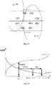
- the time for preparation can be modeled as a constant protocol delay, denoted as P in Fig. 14 .
- the serving cell After the preparation is completed, the serving cell transmits a handover command message to the UE.
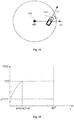
- the information regarding a movement of the wireless communication apparatus 100 with respect to the serving base station acquired by the acquiring unit 111 may include an angle between a movement direction of the wireless communication apparatus 100 and a radial direction of the wireless communication apparatus 100 with respect to the serving base station.
- the radial direction of the wireless communication apparatus 100 with respect to the serving base station refers to a direction of a half-line starting from the position of the serving base station and passing through the wireless communication apparatus 100 (for example, the direction indicated by EV in Fig. 15 ).
- the acquiring unit 111 may be configured to acquire the information regarding movement by determining the radial direction based on the position information of the serving base station and the position information of the wireless communication apparatus 100.
- the position information of the serving base station may be acquired based on a measurement control signaling from the serving base station.
- the position information of the serving base station may be acquired based on a system information block from the serving base station.
- a traveling direction of a vehicle 1510 as an example of the user equipment is D v
- the radial direction of the vehicle 1510 with respect to a cell of a serving base station 1520 thereof (that is, the radius direction of a circle centered at the base station 1520 and passes through the vehicle 1510) is EV
- the angle between D v and EV is ⁇ .
- the angle may be calculated according to Equation (2) below.
- ⁇ cos ⁇ 1 EV ⁇ ⁇ D v ⁇ EV ⁇ ⁇ D v ⁇
- the radial direction EV of the vehicle 1510 with respect to the cell of the serving base station 1520 may be, for example, calculated according to the following Equation (3).
- EV ⁇ v 1 v 2 ⁇ e 1 e 2
- ( v 1 , v 2 ) is the coordinate of the vehicle 1510
- ( e 1 , e 2 ) is the coordinate of the eNB.
- the coordinate ( v 1 , v 2 ) of the vehicle is acquired, for example, by the GPS device of the vehicle, and the coordinate ( e 1 , e 2 ) of the base station is obtained, for example, through a signaling from the base station.
- the coordinate ( e 1 , e 2 ) of the eNB may be embedded into (measurement control measConfig in) a message (RRCConnectionReconfigurtion) for reconfiguring radio resource control (RRC) transmitted by the eNB.
- RRC radio resource control
- Table 1 Format of the Measurement Control Signaling coordinate of the eNB measurement control
- the coordinate ( e 1 , e 2 ) of the eNB may also be contained in a system information block, such as MIB or SIB 1.
- the vehicle is taken as an example of the user equipment.
- the V2V communication scenario which is one of the application scenarios of the embodiment of the present disclosure is briefly described.
- Communication resources used by vehicles in the V2V communication are allocated by the eNB of a current serving cell.
- the communication resource is not authorized by the eNB of the cell, which may cause interference to other users in the cell. Therefore, the handover problem also needs to be considered in the V2V communication.
- the V2V communication scenario shown in Fig. 13 many vehicles on a road perform V2V communication within a coverage of a cellular network.
- the vehicle can easily move from the current cell to the neighboring cell, and thus cell handovers occur frequently.
- a V2V communication (especially when it involves road safety information) has higher requirements on communication delay and information detection rate. Therefore, the solution of the embodiment of the present disclosure, which helps to improve the efficiency and/or accuracy of the cell handover process, is particularly meaningful to the V2V application scenario.
- the embodiments of the present disclosure are also applicable to wireless communication scenarios other than V2V, such as V2X.
- the adjusting unit 113 may be configured to adjust the trigger condition for a transmission of the measurement report as follows.
- the time-to-trigger is shortened in a case where the information regarding movement of the wireless communication apparatus 100 with respect to the serving base station indicates that the wireless communication apparatus 100 moves away from the serving base station.
- the time-to-trigger is adjusted based on the time-to-trigger set in a conventional or existing manner, that is, the adjustment may be adjusting the time-to-trigger already set in the conventional or existing manner.
- the adjustment on the trigger condition by the adjusting unit 113 may include: shortening the time-to-trigger for triggering the transmission of the measurement report with decrement of an absolute value of the angle, in a case where the absolute value of the angle is less than a predetermined threshold, where the predetermined threshold being greater than 0° and less than or equal to 90°.
- the adjusting unit 113 may be configured to make the time-to-trigger be not less than a predetermined lower limit value.
- the predetermined lower limit value may be determined based on conditions such as an actual application scenario and a system configuration, and the predetermined lower limit value reflects a maximum tolerable limit for occurrence of the ping-pong effect.
- the time-to-trigger TTT for the transmission of the measurement report may be adjusted according to the following Equation (4).
- TTT f min TTT ⁇ a + sin ⁇ , TTT
- TTT f is the adjusted value of TTT, ⁇ ⁇ [0,90°], and ⁇ is a constant greater than 0 and less than 1 to ensure that TTT f is greater than zero.
- TTT f is a piecewise function
- the value of ⁇ determines a lower bound of TTT f which is ⁇ ⁇ TTT
- an upper bound of TTT f is TTT.
- TTT f is a strictly monotonically increasing function of ⁇ .
- TTT f is TTT.
- TTT f the minimum value of TTT f is 1 ⁇ ⁇ 2 2 ⁇ TTT .
- TTT f reaches the maximum value which is TTT.
- the TTT f may be determined according to the following Equation (5).
- TT T f a ⁇ TTT + 1 ⁇ a ⁇ sin ⁇ ⁇ TTT , ⁇ ⁇ 0,90 °
- TTT f ranges from ⁇ ⁇ TTT to TTT, and TTT f is a strictly monotonically increasing function of ⁇ in the range ⁇ ⁇ [0,90°].
- the adjusting unit 113 may be further configured to adjust the time-to-trigger based on a movement velocity of the wireless communication apparatus 100.
- the TTT may be adjusted according to a function generally expressed by the following Equation (6).
- TTT f f sf ⁇ ⁇ TTT , ⁇ ⁇ 0,90 °
- sf is a speed factor used to indicate whether the movement velocity of the wireless communication apparatus 100 is high speed, medium speed or low speed.
- f function is an increasing function of ⁇ , and a range of f function is [ ⁇ ⁇ sf ⁇ TTT, sf ⁇ TTT].
- ⁇ may be considered as a factor that determines how fast the vehicle leaves the cell of the serving base station thereof.
- the parameter ⁇ in Equation (6) may be included in measConfig cell delivered by the eNB.
- ⁇ may be set as small as possible, which is beneficial for the vehicle to reduce the TTT and realize fast handover.
- a too small ⁇ may result in a too small TTT and result in more frequent cell reselections.
- the parameters such as ⁇ and a specific form of the function f may be appropriately set according to specific applications.
- the time-to-trigger for the report of the measurement report may be effectively shortened by using the information regarding movement of a user equipment, such as the position and the traveling direction of a vehicle.
- the movement direction of the wireless communication apparatus 100 may include a real-time movement direction of the wireless communication apparatus, an average movement direction of the wireless communication apparatus during a previous predetermined time period, or an estimated average movement direction of the wireless communication apparatus during a subsequent predetermined time period. More specifically, in the V2V scenario, the movement direction of the vehicle may include, for example:
- the controlling unit 115 may control the transmission of the measurement report based on the trigger condition adjusted by the adjusting unit 113 as follows.
- the measurement report is transmitted in a case where a difference between a reference signal received power of the serving base station and a reference signal received power of a target base station for performing the cell handover is continuously greater than a predetermined threshold during the adjusted time-to-trigger.
- the entry of the trigger event for the measurement report may also be controlled based on the information regarding movement.
- the controlling unit 115 may be configured to control to enter into and/or exit from the trigger event for the measurement report for performing the cell handover based on the information regarding movement of the wireless communication apparatus 100 with respect to the serving base station.
- controlling to enter into and/or exit from the trigger event based on the information for movement may include: making an entry condition of entering into the trigger event at least include that the wireless communication apparatus moves away from the serving base station; and/or exiting from the trigger event in a case where the wireless communication apparatus moves towards the serving base station.
- the entry condition may further include that a difference between a reference signal received power of the serving base station and a reference signal received power of a target base station for performing the cell handover is greater than a predetermined threshold.
- the controlling unit 115 may control to enter into and exit from the trigger event (such as the A3 event) according to the following conditions.
- the wireless communication apparatus 200 includes a processor 210 and a transceiving device 220.
- the processor 210 includes an acquiring unit 211, an adjusting unit 213 and a controlling unit 215, the configurations of which are similar to the acquiring unit 111, the adjusting unit 113 and the controlling unit 115 described with reference to Fig. 1 respectively, and a detailed description thereof is omitted herein.
- the transceiving device 220 is configured to transmit the measurement report for performing cell handover to another wireless communication apparatus in proximity-based service direct communication with the wireless communication apparatus 200.
- the wireless communication apparatus can be applied to a scenario in which joint handover is performed on the wireless communication apparatuses in proximity-based service direct communication with each other.
- the eNB may regard the two communication parties as a whole to judge whether it is necessary to perform cell handover.
- the wireless communication apparatus 200 may provide its measurement report to another wireless communication apparatus, and the another wireless communication apparatus provides the measurement reports of the wireless communication apparatus 200 together with the another wireless communication apparatus to the serving base station, and the base station performs a joint judgment for the cell handover of these two communication apparatuses.
- the transceiving device 220 may also be configured to receive, from one or more other wireless communication apparatuses in proximity-based service direct communication with the wireless communication apparatus 200, measurement reports for performing the cell handover.
- the wireless communication apparatus 200 may receive the measurement reports from other wireless communication apparatuses and provides the measurement reports of other wireless communication apparatuses together with the measurement report of the wireless communication apparatus 200 to the serving base station, and the base station performs a joint judgment for the cell handover of these communication apparatuses.
- the transceiving device 220 may be configured to transmit the measurement reports received from another wireless communication apparatus during a predetermined time period together with the measurement report of the wireless communication apparatus 200 to the serving base station.
- the eNB may regard the receiving part and the transmitting party as a whole to judge whether it is necessary to perform cell handover.
- a common handover decision is made (S1750), thus the probability of wrong handover judgment is reduced.
- the eNB individually hands over the vehicle that transmits the first measurement report (S1740).
- the eNB receives measurement reports from two communication parties in the V2V communication.
- the communication apparatus responsible for uniformly transmitting the measurement reports transmits two measurement reports to the eNB in a case where the communication apparatus receives the measurement report from the communication object in the V2V communication in a predetermined time period (corresponding to S1750 in Fig. 17 ), otherwise, the communication apparatus only transmit its own measurement report (corresponding to S1740 in Fig. 17 ).
- the trigger condition such as TTT and HOM may be further reduced while guaranteeing the accuracy of the handover judgment.
- Adjustment of the trigger condition may be determined based on a relative speed, a relative distance and the like between apparatuses. In other words, according to some embodiments, the adjustment of the trigger condition for the transmission of the measurement report depends not only on the movement of the apparatus with respect to the base station, but also on the relative movement between the apparatuses.
- the acquiring unit 111 may further be configured to acquire information regarding a distance and/or a relative speed between the wireless communication apparatus 100 and another wireless communication apparatus in proximity-based service direct communication with the wireless communication apparatus 100.
- the adjusting unit 113 may further be configured to adjust the trigger condition for the transmission of the measurement report based on the distance and/or the relative speed between the wireless communication apparatus and the another wireless communication apparatus.
- the adjusting unit 113 may be configured to reduce a time-to-trigger and/or a handover margin for triggering the transmission of the measurement report with increment of the distance between the wireless communication apparatus 100 and the another wireless communication apparatus.
- ⁇ in Equations (7) and (8) may be related to the distance between a receiving vehicle and a transmitting vehicle.
- a transmitting vehicle periodically broadcasts V2V information.
- the receiving vehicle After receiving the V2V information, the receiving vehicle periodically transmits acknowledgment information (ACK).
- the acknowledgment information is required to include position information V R of the receiving vehicle.
- the transmitting vehicle calculates an inter-vehicle distance based on position information V T of the transmitting vehicle and the position information V R of the receiving vehicle in the acknowledgment information.
- a less inter-vehicle distance D corresponds to ⁇ closer to 1
- a greater inter-vehicle distance D corresponds to a less ⁇ .
- ⁇ may be regarded as a parameter for measuring a coupling degree between the transmitting vehicle and the receiving vehicle.
- ⁇ is close to 1 when the inter-vehicle distance D is close to 0. HOM and TTT are almost unchanged. A greater inter-vehicle distance D corresponds to a less ⁇ . However, the coverage of the V2V communication is about 100 meters, the value of ⁇ may not be too small. The value of ⁇ in the V2V information may be updated when the transmitting vehicle transmits the V2V information in the next period.
- the traveling directions of two communication vehicles in the V2V scenario are the same.
- the traveling directions of two communication parties are opposite, the basis of the above joint judgment is in lack, and the transmitting vehicle and the receiving vehicle should be judged and handed over separately.
- the traveling directions being opposite refers to that two communication parties in the V2V communication travels along the opposite extending directions of the traveling road.
- the judgment manner may be selected at base station side based on traveling directions of a transmitting party and a receiving party. For example, resource configuration information for the proximity-based service direct communication delivered by the base station before the two parties start the communication indicates whether the independent judgment manner or the joint judgment manner is used for two communication parties. In addition, whether the traveling directions are different or same may be determined by, for example, a measurement by the base station.
- the user equipment may report the measurement report for the cell handover in the following manners, for example.
- the user equipments performing the proximity-based service direct communication report the measurement reports to the base station separately.
- the user equipments performing the proximity-based service direct communication transmit the measurement reports to one of the user equipments.
- the one user equipment gathers the measurement reports of other user equipments received in a predetermined time period and then reports the collected measurement reports together with the measurement report of the one user equipment to the base station. If no measurement report of another user equipment is received within a predetermined time period, the one user equipment reports only its own measurement report.
- the base station performs a handover judgment based on the received single measurement report or gathered measurement reports.
- both the independent judgment manner and the joint judgment manner may be used.
- the base station may configure at least two TTT values for the handover event, used for the independent judgment manner and the joint judgment manner, respectively.
- the UE may, for example, respectively report the measurement reports for the two TTT values and corresponding processes.
- the base station performs the handover judgment based on a first received measurement report.
- multiple TTTs may be configured for the A3 event.
- the joint judgment manner is used for the handover condition for the user equipments in proximity-based service direct communication with each other, thereby the accuracy of the judgment and the speed of judgment can be improved.
- the user equipments performing the proximity-based service direct communication with each other may perform the cell handover in groups.
- a target eNB may reserve two Cell Radio Network Temporary Identifiers (C-RNTIs), two random access preamble sequences.
- C-RNTIs Cell Radio Network Temporary Identifiers
- the source eNB delivers the reserved resources to one of the vehicles, which informs the reserved resources to the other vehicle, and a group handover process is performed.
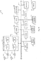
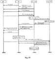
- step S1 the source eNB notifies the vehicles TV and RV (TV and RV are the vehicles performing V2V communication) of a measurement configuration message by the measConfig cell carried in the RRCConnectionReconfigurtion message, that is, a measurement control is delivered, the message includes coordinate information of the source base station.
- step S2 TV and RV report the measurement reports to the eNB.
- the measurement report includes, for example, a 1-bit transmission and reception indication bit and a 1-bit priority indication bit.
- step S3 the source eNB performs the joint judgment.
- step S4 the source eNB transmits a handover request to the target eNB.
- the handover request contains the necessary information required by the target eNB for the handover, such as a target cell identify, C-RNTIs of the transmitting vehicle and the receiving vehicle in the source cell included in the RRC context.
- admission control is performed in step S5.
- the target eNB configures the required communication resources, reserves two C-RNTIs and two random access preamble sequences.
- step S6 the target eNB transmits a handover request acknowledgment message to the source eNB, the message includes an RRC container, specific content of which is a handover command for triggering the UE to perform handover.
- the handover command includes two new C-RNTIs, and also carries two random access dedicated Preamble codes, access parameters and system information or the like.
- step S7 the source eNB transmits an RRCConnectionReconfigurtion message to the transmitting vehicle, the message includes the RRC container in the previous step and handover resource allocation information.
- step S8 TV informs RV of the handover resource allocation information, new C-RNTI and Preamble code, access parameters, system information, and the like.
- TV and RV may employ resources allocated in a handover resource pool (as will be described later) to perform communication.
- step S9 TV and RV initiate a non-contention based random access to the target cell.
- step S10 the target eNB allocates new resources to the transmitting vehicle.
- step S11 the target eNB notifies the source eNB of the successful handover, and notifies the source eNB that the resource in the handover resource pool may be released.
- step S12 the source eNB releases the handover resource and control plane related resources.
- the signaling overhead for the cell handover may be effectively reduced through the group handover.
- the life cycle of the resource of the resource pool may be set to be 50ms, and the source eNB automatically releases the resource in the handover resource pool after the timing ends. If there is no idle handover resource to be allocated to non-safety related vehicle, the handover resource allocation information is not included in S7, but information of the new C-RNTI and Preamble or the like is still included. In S8, the transmitting vehicle informs the receiving vehicle of the new C-RNTI and Preamble code, access parameters, system information, and the like. Since there is no allocated handover resource, there is a handover interruption after the vehicle is disconnected form the source cell, however, the group handover can still be implemented.
- the configuration of the handover resource pool will be described in more detail below.
- LTE hard handover results in an interruption time period after the UE disconnects from the source base station and before the UE establishes a connection with the target base station.
- part of the time-frequency resources may be reserved to form the handover resource pool.
- a time-frequency resource in the handover resource pool is allocated to the transmitting vehicle for terminal-to-terminal communication between vehicles until the vehicle establishes a connection with the target base station and is allocated with new resources.
- the handover resource pool may be configured according to the following principles.
- the source cell and the target cell share the same handover resource pool, and it is ensured that the use of the handover resource pool does not interfere with other users in the source cell and the target cell.
- the source cell and the target cell know about the usage of the handover resource pool, to avoid a case where the same resource is repeatedly allocated.
- the resources in the handover resource pool may be reused by UEs located in the center of the cell to improve a resource utilization rate.
- the handover resource pool may be divided into two parts due to the different traveling directions of the vehicles on both sides of the road:
- One part includes handover resources used by the vehicle handing over from cell 1 to cell 2.
- the other part includes handover resources used by the vehicle handing over from cell 2 to cell 1.
- resource pool configuration information may be updated every T time period.
- the issue of resource competition may be taken into account when allocating the handover resources.
- the V2V communications may be classified as safety-related V2V communication and non-safety-related V2V communication, and a high priority and a low priority are given thereto, respectively.
- dedicated time-frequency resources are further reserved in each of the two parts of the handover resource pool, for being allocated to safety-related vehicle for use when the remaining part of the resources are depleted.
- the dedicated time-frequency resources are called as a first part, the remaining part of the resources is called as a second part.
- the first part of resources will not be allocated.
- the resources are allocated in the order of the high priority to the low priority.
- the above example resource competition scheme is provided to ensure that the requirement of safety-related V2V communication vehicles is met in a case that the handover resources are not sufficient.
- resources in the handover resource pool are allocated to the user equipment to ensure continuity of the communication of the user equipment, and the configuration of the resource pool is dynamically adjusted to ensure that the user with the high priority obtains preferentially the handover resources.
- the joint judgment in the broadcast scenario requires the source base station to know information of the vehicles performing the V2V communication. Therefore, an identifier (such as C-RNTI) of the vehicle should be added to the V2V broadcast information transmitted by the vehicle.
- C-RNTI identifier
- a broadcast group information table may be established at the eNB end, as shown in Table 2 below, in which C-RNTI of the broadcasting vehicle and the receiving vehicle in the broadcast group is recorded. Table 2. Broadcast group member information table Members C-RNTI Transmitting vehicle C-RNTI Receiving vehicle 1 C-RNTI1 Receiving vehicle 2 C-RNTI2
- the receiving vehicle When the receiving vehicle loses the signal of the broadcasting vehicle, the receiving vehicle transmits a request to the eNB to exit, and the eNB deletes the information of the vehicle in the broadcast group member information table, so that the eNB can know the information of the member in the broadcast group in a real time manner.
- the joint judgment is described as follows. It is assumed that there are 7 vehicles in the group, including 1 transmitting vehicle and 6 receiving vehicles. For example, when the eNB receives the measurement reports transmitted by the transmitting vehicle and more than half of the receiving vehicles, the eNB may make a handover decision without waiting until all the vehicles report the measurement reports, which can reduce the handover delay.
- the source eNB may transmit a handover request to the target eNB, the handover request includes the broadcast group information table.
- the target eNB transmits handover request acknowledgment information to the source eNB.
- the specific content of the RRC container may include a handover command for triggering the UE to perform handover.
- the handover command includes multiple old C-RNTIs and new C-RNTIs, and further carries a random access dedicated Preamble code, access parameters and system information or the like.
- the old C-RNTIs correspond to the new C-RNTIs and Peamble in a one to one manner.
- the source eNB transmits an RRCConnectionReconfigurtion message to the transmitting vehicle, the messages includes the RRC container in the previous step and the handover resource allocation information.
- the transmitting vehicle broadcasts the handover resource allocation information, new C-RNTIs and Preamble code, access parameters and system information or the like.
- the receiving vehicle acquires new C-RNTIs and Preamble according to the old C-RNTIs.
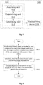
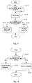
- a wireless communication method for user equipment side includes steps.
- step S310 information regarding movement of a wireless communication apparatus with respect to a serving base station thereof is acquired.
- step S320 a trigger condition for a measurement report for performing a cell handover is adjusted based on the information.
- step S330 a transmission of the measurement report is controlled based on the adjusted trigger condition.
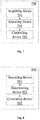
- the embodiments of the wireless communication apparatus and the wireless communication method for user equipment side are described above, a wireless communication apparatus and a wireless communication method for base station side are further provided according to the embodiments of the present disclosure.
- a wireless communication device 400 for base station side includes one or more processors 410.
- the processor 410 includes an acquiring unit 411, a determining unit 413, and a generating unit 415.
- the acquiring unit 411 is configured to acquire a measurement report which is transmitted by a user equipment in a case where a trigger condition is met, where the trigger condition is related to a movement of the user equipment with respect to the base station.
- the determining unit 413 is configured to determine, based on the measurement report, whether to perform a cell handover for the user equipment.
- the generating unit 415 is configured to generate a handover command for the user equipment in a case where it is determined to perform the cell handover.
- the trigger condition is adjusted by the user equipment based on the movement of the user equipment with respect to the base station.
- the movement of the user equipment with respect to the base station is determined by the user equipment based on the position of the base station.
- the wireless communication apparatus for base station side is configured to transmit the position information of the base station to the user equipment.
- a wireless communication apparatus 500 for base station side includes one or more processors 510 and a transceiving device 520.
- the processor 510 includes an acquiring unit 511, a determining unit 513 and a generating unit 515, the configurations of which are similar to the above-mentioned acquiring unit 411, the determining unit 413 and the generating unit 415, respectively.
- the transceiving device 520 is configured to transmit position information of the base station to the user equipment.
- the transceiving device 520 is configured to transmit the position information of the base station through a radio resource control signaling. For example, the transceiving device 520 may notify the user equipment of a measurement configuration message through the measConfig cell carried in the RRCConnectionReconfigurtion message, the measurement configuration message may include the position information of the base station.
- the position information of the base station may also be embedded in a system information block (such as MIB or SIB1) to be transmitted to the user equipment.
- MIB system information block
- the user equipment may adjust the trigger condition for the measurement report based on the information from the base station.
- the adjustment of the triggering condition may be related to an angle between a movement direction of the user equipment and a radial direction of the user equipment with respect to the base station.
- the radial direction may be determined based on the position information of the base station and the position information of the user equipment.
- the wireless communication apparatus for base station side may perform group handover on user equipments.
- the wireless communication apparatus may be configured to generate a common handover command for a first user equipment and a second user equipment in proximity-based service direct communication with the first user equipment, in a case where a measurement report from the second user equipment is received during a predetermined time period after a measurement report for the cell handover from the first user equipment is received.
- the base station receives measurement reports from multiple user equipments.
- the measurement reports of multiple user equipments may also be collected by one of the user equipments and transmitted to the base station together by the one user equipment.
- the wireless communication apparatus may be configured to generate, based on measurement reports of a first user equipment and at least one other user equipment in proximity-based service direct communication with the first user equipment received from the first user equipment, a common handover command for the first user equipment and the at least one other user equipment.
- a measurement report transmitted by a user equipment in a case where a trigger condition is met is acquired, where the trigger condition is related to a movement of the user equipment with respect to a base station.
- a handover command for the user equipment is generated in a case where it is determined to perform the cell handover.
- various steps of the methods above and various modules and/or units of the apparatuses above may be implemented as software, firmware, hardware or a combination thereof.
- programs consisting of the software for implementing the methods above are installed to a computer with a dedicated hardware structure (for example a general-purpose computer 900 shown in Fig. 9 ) from the storage medium or the network.
- the computer can perform various types of functions when installed with various types of programs.
- a central processing unit (CPU) 901 performs various types of processing according to programs stored in a read only memory (ROM) 902 or programs loaded from a storage section 908 to a random access memory (RAM) 903. Data required when the CPU 901 performs various types of processing is also stored in the RAM 903 as needed.
- the CPU 901, the ROM 902 and the RAM 903 are linked to each other via a bus 904.
- An input/output interface 905 is also linked to the bus 904.
- the following components are linked to the input/output interface 905: an input section 906 (including a keyboard, and a mouse and so on), an output section 907 (including a display, for example a cathode ray tube (CRT) and a liquid crystal display (LCD), and a loudspeaker), a storage section 908 (including a hard disk and so on), and a communication section 909 (including a network interface card for example a LAN card, and a modem).
- the communication section 909 performs communication processing via a network for example the Internet.
- a driver 910 may also be linked to the input/output interface 905 as needed.
- a removable medium 911 for example a magnetic disk, an optical disk, a magnetic-optical disk and a semiconductor memory may be installed on the driver 910 as needed, such that computer programs read from the removable medium 911 are installed on the storage section 908 as needed.
- programs consisting of the software are installed from the network for example the Internet or the storage medium for example the removable medium 911.
- the storage medium is not limited to the removable medium 911 shown in Fig. 9 which stores programs and is distributed separately from the device to provide the programs to the user.
- the removable medium 911 include: a magnetic disk (including a floppy disk (registered trademark), an optical disk (including a compact disk read only memory (CD-ROM) and a digital versatile disk (DVD)), a magnetic-optical disk (including a mini disk (MD) (registered trademark)), and a semiconductor memory.
- the storage medium may be a hard disk included in the ROM 902 and the storage section 908 which stores programs. The storage medium and the device including thereof together are distributed to the user.
- a program product storing machine readable instruction codes is further provided according to the embodiments of the present disclosure.
- the instruction codes When read and executed by a machine, the instruction codes cause the machine to perform the method according to the embodiment of the present disclosure.
- a storage medium for carrying the program product storing the machine readable instruction codes is further provided according to the present disclosure.
- the storage medium includes but not limited to a floppy disk, an optical disk, a magnetic-optical disk, a storage card and a memory stick and so on.
- the embodiments of the present disclosure further relate to an electronic device in the following.
- the electronic device may be implemented as any type of evolved node B (eNB), such as a macro eNB and a small eNB.
- the small eNB may be an eNB covering a cell smaller than a macro cell, such as a pico eNB, a micro eNB and a home (femto) eNB.
- the electronic device may be implemented as any other type of base stations, such as a NodeB and a base transceiver station (BTS).
- BTS base transceiver station
- the electronic device may include: a body configured to control wireless communication (also referred to as a base station device); and one or more remote radio heads (RRH) located at positions different from the body.
- a body configured to control wireless communication also referred to as a base station device
- RRH remote radio heads
- various types of terminals described in the following each may function as a base station to operate by performing functions of the base station temporarily or in a semi-permanent manner.
- the electronic device may be implemented as mobile terminals (such as a smart phone, a tablet personal computer (PC), a notebook PC, a portable game terminal, a portable/dongle mobile router and a digital camera) or a vehicle terminal (such as an automobile navigation device).
- the electronic device may be a wireless communication module installed on each of the above terminals (such as an integrated circuit module including one or more chips).
- Fig. 10 is a block diagram showing an example of a schematic configuration of a smart phone 2500 to which the technology according to the present disclosure may be applied.
- the smart phone 2500 includes a processor 2501, a memory 2502, a storage 2503, an external connection interface 2504, a camera 2506, a sensor 2507, a microphone 2508, an input apparatus 2509, a display apparatus 2510, a speaker 2511, a radio communication interface 2512, one or more antenna switches 2515, one or more antennas 2516, a bus 2517, a battery 2518, and an auxiliary controller 2519.
- the processor 2501 may be, for example, a CPU or a system on a chip (SoC), and controls functions of an application layer and another layer of the smart phone 2500.
- the memory 2502 includes RAM and ROM, and stores a program that is executed by the processor 2501, and data.
- the storage 2503 may include a storage medium such as a semiconductor memory and a hard disk.
- the external connection interface 2504 is an interface for connecting an external apparatus such as a memory card and a universal serial bus (USB) apparatus to the smart phone 2500.
- USB universal serial bus
- the camera 2506 includes an image sensor such as a charge coupled device (CCD) and a complementary metal oxide semiconductor (CMOS), and generates a captured image.
- the sensor 2507 may include a group of sensors such as a measurement sensor, a gyro sensor, a geomagnetic sensor, and an acceleration sensor.
- the microphone 2508 converts sounds that are inputted to the smart phone 2500 into audio signals.
- the input apparatus 2509 includes, for example, a touch sensor configured to detect touch onto a screen of the display apparatus 2510, a keypad, a keyboard, a button, or a switch, and receive an operation or information inputted from a user.
- the display apparatus 2510 includes a screen such as a liquid crystal display (LCD) and an organic light-emitting diode (OLED) display, and displays an output image of the smart phone 2500.
- the speaker 2511 converts audio signals that are outputted from the smart phone 2500 into sounds.
- the radio communication interface 2512 supports any cellular communication scheme such as LTE and LTE-Advanced, and performs radio communication.
- the radio communication interface 2512 may typically include, for example, a base band (BB) processor 2513 and a radio frequency (RF) circuit 2514.
- the BB processor 2513 may perform, for example, encoding/decoding, modulating/demodulating, and multiplexing/demultiplexing, and performs various types of signal processing for radio communication.
- the RF circuit 2514 may include, for example, a mixer, a filter, and an amplifier, and transmits and receives radio signals via the antenna 2516.
- the radio communication interface 2512 may be a chip module having the BB processor 2513 and the RF circuit 2514 integrated thereon.
- the radio communication interface 2512 may include multiple BB processors 2513 and multiple RF circuits 2514, as illustrated in Fig. 10 .
- Fig. 10 illustrates the example in which the radio communication interface 2512 includes the multiple BB processors 2513 and the multiple RF circuits 2514, the radio communication interface 2512 may also include a single BB processor 2513 or a single RF circuit 2514.
- the radio communication interface 2512 may support another type of radio communication scheme such as a short-distance radio communication scheme, a near field communication scheme, and a radio local area network (LAN) scheme.
- the radio communication interface 2512 may include the BB processor 2513 and the RF circuit 2514 for each radio communication scheme.
- Each of the antenna switches 2515 switches connection destinations of the antennas 2516 among multiple circuits (such as circuits for different radio communication schemes) included in the radio communication interface 2512.
- Each of the antennas 2516 includes a single or multiple antenna elements (such as multiple antenna elements included in an MIMO antenna), and is used for the radio communication interface 2512 to transmit and receive radio signals.
- the smart phone 2500 may include the multiple antennas 2516, as illustrated in Fig. 10 .
- Fig. 13 illustrates the example in which the smart phone 2500 includes the multiple antennas 2516, the smart phone 2500 may also include a single antenna 2516.
- the smart phone 2500 may include the antenna 2516 for each radio communication scheme.
- the antenna switches 2515 may be omitted from the configuration of the smart phone 2500.
- the bus 2517 connects the processor 2501, the memory 2502, the storage 2503, the external connection interface 2504, the camera 2506, the sensor 2507, the microphone 2508, the input apparatus 2509, the display apparatus 2510, the speaker 2511, the radio communication interface 2512, and the auxiliary controller 2519 to each other.
- the battery 2518 supplies power to blocks of the smart phone 2500 illustrated in Fig. 13 via feeder lines, which are partially shown as dashed lines in the figure.
- the auxiliary controller 2519 operates a minimum necessary function of the smart phone 2500, for example, in a sleep mode.
- the transceiving device 220 described with reference to Fig. 2 may be implemented by the radio communication interface 2512. At least a part of functions of the units described with reference to Fig. 1 and Fig. 2 may be implemented by the processor 2501 or the auxiliary controller 2519. For example, power consumption of the battery 2518 may be reduced by performing a part of the functions of the processor 2501 by the auxiliary controller 2519. In addition, the processor 2501 or the auxiliary controller 2519 may perform at least a part of the functions of the units described with reference to Fig. 1 and Fig. 2 by executing programs stored in the memory 2502 or the storage 2503.
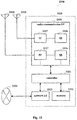
- Fig. 11 is a block diagram showing an example of a schematic configuration of an eNB to which the technology according to the present disclosure may be applied.
- An eNB 2300 includes one or more antennas 2310 and a base station device 2320.
- the base station device 2320 and each antenna 2310 may be connected to each other via a radio frequency (RF) cable.
- RF radio frequency
- Each of the antennas 2310 includes one or more antenna elements (such as multiple antenna elements included in a multiple input multiple output (MIMO) antenna) and is used by the base station device 2320 to transmit and receive a radio signal.
- the eNB 2300 may include multiple antennas 2310.
- the multiple antennas 2310 may be compatible with multiple frequency bands used by the eNB 2300.
- Fig. 11 shows an example in which the eNB 2300 includes multiple antennas 2310, the eNB 2300 may include a single antenna 2310.
- the base station device 2320 includes a controller 2321, a memory 2322, a network interface 2323 and a radio communication interface 2325.
- the controller 2321 may be a CPU or a DSP and control various functions of higher layers of the base station device 2320. For example, the controller 2321 generates a data packet based on data in a signal processed by the radio communication interface 2325, and transfers the generated packet via a network interface 2323. The controller 2321 may bind data from multiple baseband processors to generate a binding packet and transfer the generated binding packet. The controller 2321 may have logic functions for performing the following control: radio resource control, radio carrying control, mobility management, admission control and schedule. The control may be performed in combination with an adjacent eNB or a core network node.
- the memory 2322 includes RAM and ROM, and stores programs executed by the controller 2321 and various types of control data (such as a terminal list, transmission power data and scheduling data).
- the network interface 2323 is configured to connect the base station device 2320 to a communication interface of the core network 2324.
- the controller 2321 may communication with the core network node or another eNB via the network interface 2323.
- the eNB 2300 and the core network node or another eNB may be connected to each other via a logic interface (such as an S1 interface and an X2 interface).
- the network interface 2323 may be a wired communication interface or a radio communication interface for a wireless backhaul line. If the network interface 2323 is a radio communication interface, the network interface 2323 may use a higher frequency band for wireless communication as compared with the frequency band used by the radio communication interface 2325.
- the radio communication interface 2325 supports any cellular communication scheme (such as long term evolution (LTE) and LTE-advanced), and provides a radio connection to a terminal located in a cell of the eNB 2300 via an antenna 2310.
- the radio communication interface 2325 may generally include a BB processor 2326 and an RF circuit 2327.
- the BB processor 2326 may perform for example encoding/decoding, modulating/demodulating and multiplexing/demultiplexing, and various types of signal processing of layers (such as L1, medium access control (MAC), radio link control (RLC) and packet data convergence protocol (PDCP)).
- the BB processor 2326 may have a part or all of the above logic functions.
- the BB processor 2326 may be a memory storing communication control programs or a module including a processor configured to execute programs and a related circuit. Updating programs may change functions of the BB processor 2326.
- the module may be a card or a blade inserted into a slot of the base station device 2320. Alternatively, the module may be a chip installed on the card or the blade.
- the RF circuit 2327 may include for example a mixer, a filter or an amplifier, and transmits and receives a radio signal via the antenna 2310.
- the radio communication interface 2325 may include multiple BB processors 2326.
- the multiple BB processors 2326 may be compatible with multiple frequency bands used by the eNB 2300.
- the radio communication interface 2325 may include multiple RF circuits 2327.
- the multiple RF circuits 2327 may be compatible with multiple antenna elements.
- Fig. 11 shows an example in which the radio communication interface 2325 includes multiple BB processors 2326 and multiple RF circuits 2327, the radio communication interface 2325 may include a single BB processor 2326 or a single RF circuit 2327.
- the transceiving device 520 described with reference to Fig. 5 may be implemented by the radio communication interface 2325. At least a part of the functions of the units described with reference to Fig. 4 and Fig. 5 may be implemented by the controller 2321.
- the controller 2321 may perform at least a part of the functions of the units described with reference to Fig. 4 and Fig. 5 by performing the programs stored in the memory 2322.
- Fig. 12 is a block diagram showing an example of a schematic configuration of a car navigation device 1320 to which the technology according to the present disclosure may be applied.
- the car navigation device 1320 includes a processor 1321, a memory 1322, a global positioning system (GPS) module 1324, a sensor 1325, a data interface 1326, a content player 1327, a storage medium interface 1328, an input apparatus 1329, a display apparatus 1330, a speaker 1331, a radio communication interface 1333, one or more antenna switches 1336, one or more antennas 1337, and a battery 1338.
- GPS global positioning system
- the processor 1321 may be, for example, a CPU or a SoC, and controls a navigation function and another function of the car navigation device 1320.
- the memory 1322 includes RAM and ROM, and stores a program that is executed by the processor 1321, and data.
- the GPS module 1324 uses GPS signals received from a GPS satellite to measure a position (such as latitude, longitude, and altitude) of the car navigation device 1320.
- the sensor 1325 may include a group of sensors such as a gyro sensor, a geomagnetic sensor, and an air pressure sensor.
- the data interface 1326 is connected to, for example, an in-vehicle network 1341 via a terminal that is not shown, and acquires data generated by the vehicle, such as vehicle speed data.
- the content player 1327 reproduces content stored in a storage medium (such as a CD and a DVD) that is inserted into the storage medium interface 1328.
- the input apparatus 1329 includes, for example, a touch sensor configured to detect touch on a screen of the display apparatus 1330, a button, or a switch, and receives an operation or information inputted from a user.
- the display apparatus 1330 includes a screen such as a LCD or an OLED display, and displays an image of the navigation function or content that is reproduced.
- the speaker 1331 outputs sounds of the navigation function or the content that is reproduced.
- the radio communication interface 1333 supports any cellular communication scheme (such as LTE and LTE-Advanced), and performs wireless communication.
- the radio communication interface 1333 may typically include, for example, a BB processor 1334 and an RF circuit 1335.
- the BB processor 1334 may perform, for example, encoding/decoding, modulating/demodulating, and multiplexing/demultiplexing, and performs various types of signal processing for wireless communication.
- the RF circuit 1335 may include, for example, a mixer, a filter, and an amplifier, and transmits and receives radio signals via the antenna 1337.
- the radio communication interface 1333 may also be one chip module that has the BB processor 1334 and the RF circuit 1335 integrated thereon.
- the radio communication interface 1333 may include multiple BB processors 1334 and multiple RF circuits 1335, as illustrated in Fig. 12 .
- Fig. 12 illustrates the example in which the radio communication interface 1333 includes the multiple BB processors 1334 and the multiple RF circuits 1335, the radio communication interface 1333 may also include a single BB processor 1334 or a single RF circuit 1335.
- the radio communication interface 1333 may support another type of wireless communication scheme such as a short-distance wireless communication scheme, a near field communication scheme, and a wireless LAN scheme.
- the radio communication interface 1333 may include the BB processor 1334 and the RF circuit 1335 for each wireless communication scheme.
- Each of the antenna switches 1336 switches connection destinations of the antennas 1337 among multiple circuits (such as circuits for different wireless communication schemes) included in the radio communication interface 1333.
- Each of the antennas 1337 includes a single or multiple antenna elements (such as multiple antenna elements included in an MIMO antenna), and is used for the radio communication interface 1333 to transmit and receive radio signals.
- the car navigation device 1320 may include multiple antennas 1337, as illustrated in Fig. 12 . Although Fig. 13 illustrates the example in which the car navigation device 1320 includes the multiple antennas 1337, the car navigation device 1320 may also include a single antenna 1337.
- the car navigation device 1320 may include the antenna 1337 for each wireless communication scheme.
- the antenna switches 1336 may be omitted from the configuration of the car navigation device 1320.
- the battery 1338 supplies power to blocks of the car navigation device 1320 illustrated in Fig. 12 via feeder lines that are partially shown as dashed lines in the drawing.
- the battery 1338 accumulates power supplied form the vehicle.
- the transceiving device 220 described with reference to Fig. 2 may be implemented by the radio communication interface 1333.
- the processor 1321 may perform at least a part of the functions of the units described with reference to Fig. 1 and Fig. 2 by executing programs stored in the memory 1322.
- the technology of the present disclosure may also be realized as an in-vehicle system (or a vehicle) 1340 including one or more blocks of the car navigation device 1320, the in-vehicle network 1341, and a vehicle module 1342.
- the vehicle module 1342 generates vehicle data (such as vehicle speed, engine speed, and fault information), and outputs the generated data to the in-vehicle network 1341.
- reference numerals consisting of numbers are used to indicate various steps and/or units. Those skilled in the art should understand that the reference numerals are used to facilitate describing and drawing, and are not intended to indicate an order or limit in any way.
- the method according to the present disclosure is not limited to be performed in a time order described in the description, and may be performed according to other time orders, in parallel or independently. Therefore, the order in which the method described in the description is performed does not limit the technical scope of the present disclosure.
Landscapes
- Engineering & Computer Science (AREA)
- Computer Networks & Wireless Communication (AREA)
- Signal Processing (AREA)
- Mobile Radio Communication Systems (AREA)
Claims (14)
- Drahtlose Kommunikationsvorrichtung (100) für eine Anwendergerätseite, die Folgendes umfasst:
mindestens einen Prozessor (111, 113, 115), der konfiguriert ist zum:Erfassen von Informationen bezüglich einer Bewegung der drahtlosen Kommunikationsvorrichtung in Bezug auf eine ihr dienende Basisstation;Anpassen anhand der Informationen einer Auslösebedingung für eine Übertragung eines Messberichts zum Ausführen einer Zellübergabe;Erfassen von Informationen bezüglich eines Abstands und/oder einer relativen Geschwindigkeit zwischen der drahtlosen Kommunikationsvorrichtung und einer anderen drahtlosen Kommunikationsvorrichtung in direkter Kommunikation eines auf Nähe beruhenden Dienstes mit der drahtlosen Kommunikationsvorrichtung;weiteres Anpassen der Auslösebedingung anhand des Abstands und/oder der relativen Geschwindigkeit zwischen der drahtlosen Kommunikationsvorrichtung und der anderen drahtlosen Kommunikationsvorrichtung; undSteuern anhand der angepassten Auslösebedingung der Übertragung des Messberichts. - Drahtlose Kommunikationsvorrichtung nach Anspruch 1, wobei die Auslösebedingung eine Länge einer Zeit-zum Auslösen zum Auslösen der Übertragung des Messberichts umfasst und der mindestens eine Prozessor konfiguriert ist zum:
Kürzen der Zeit-zum-Auslösen in einem Fall, in dem die Informationen angeben, dass sich die drahtlose Kommunikationsvorrichtung von der dienenden Basisstation wegbewegt. - Drahtlose Kommunikationsvorrichtung nach Anspruch 2, wobei der mindestens eine Prozessor konfiguriert ist zum:
Senden des Messberichts in einem Fall, in dem ein Unterschied zwischen einer empfangenen Leistung eines Referenzsignals der dienenden Basisstation und der empfangenen Leistung eines Referenzsignals einer Zielbasisstation zum Ausführen der Zellübergabe ununterbrochen größer als ein vorbestimmter Schwellenwert während der angepassten Zeit-zum-Auslösen ist. - Drahtlose Kommunikationsvorrichtung nach Anspruch 2, wobei der mindestens eine Prozessor konfiguriert ist zum:
Anpassen der Länge der Zeit-zum-Auslösen ferner anhand einer Bewegungsgeschwindigkeit der drahtlosen Kommunikationsvorrichtung. - Drahtlose Kommunikationsvorrichtung nach Anspruch 1, wobei der Prozessor ferner konfiguriert ist zum:
Steuern anhand der Informationen, um in ein Auslöseereignis für den Messbericht einzutreten und/oder aus ihm auszutreten. - Drahtlose Kommunikationsvorrichtung nach Anspruch 5, wobei der mindestens eine Prozessor konfiguriert ist zum:Erreichen, dass eine Eintrittsbedingung des Eintretens in das Auslöseereignis zumindest enthält, dass sich die drahtlose Kommunikationsvorrichtung von der dienenden Basisstation wegbewegt; und/oderAustreten aus dem Auslöseereignis in einem Fall, in dem sich die drahtlose Kommunikationsvorrichtung in Richtung der dienenden Basisstation bewegt.
- Drahtlose Kommunikationsvorrichtung nach einem der Ansprüche 1 bis 6, wobei die Informationen bezüglich der Bewegung einen Winkel zwischen einer Bewegungsrichtung der drahtlosen Kommunikationsvorrichtung und einer radialen Richtung der drahtlosen Kommunikationsvorrichtung in Bezug auf die dienende Basisstation umfassen.
- Drahtlose Kommunikationsvorrichtung nach Anspruch 7, wobei der mindestens eine Prozessor konfiguriert ist zum:
Kürzen der Länge der Zeit-zum-Auslösen zum Auslösen der Übertragung des Messberichts mit Verringerung eines absoluten Werts des Winkels in einem Fall, in dem der absolute Wert des Winkels kleiner als ein vorbestimmter Winkelschwellenwert ist, wobei der vorbestimmte Winkelschwellenwert größer als 0° und kleiner oder gleich 90° ist. - Drahtlose Kommunikationsvorrichtung nach einem der Ansprüche 1 bis 6, die ferner Folgendes umfasst:
eine Sendeempfängervorrichtung, die konfiguriert ist zum:Senden des Messberichts an eine andere drahtlose Kommunikationsvorrichtung in direkter Kommunikation eines auf Nähe beruhenden Dienstes mit der drahtlosen Kommunikationsvorrichtung oderEmpfangen von einer oder von mehreren anderen drahtlosen Kommunikationsvorrichtung in direkter Kommunikation eines auf Nähe beruhenden Dienstes mit der drahtlosen Kommunikationsvorrichtung von Messberichten zum Ausführen einer Zellübergabe. - Drahtlose Kommunikationsvorrichtung nach Anspruch 9, wobei die Sendeempfängervorrichtung ferner konfiguriert ist zum:
Senden der Messberichte, die von den anderen drahtlosen Kommunikationsvorrichtungen während einer vorbestimmten Zeitperiode empfangen werden, zusammen mit dem Messbericht der drahtlosen Kommunikationsvorrichtung an die dienende Basisstation. - Drahtloses Kommunikationsverfahren für eine Anwendergerätseite, das Folgendes umfasst:Erfassen (S310) von Informationen bezüglich einer Bewegung einer drahtlosen Kommunikationsvorrichtung in Bezug auf eine ihr dienende Basisstation;Anpassen (S320) anhand der Informationen einer Auslösebedingung für einen Messbericht zum Ausführen einer Zellübergabe;Erfassen von Informationen bezüglich eines Abstands und/oder einer relativen Geschwindigkeit zwischen der drahtlosen Kommunikationsvorrichtung und einer anderen drahtlosen Kommunikationsvorrichtung in direkter Kommunikation eines auf Nähe beruhenden Dienstes mit der drahtlosen Kommunikationsvorrichtung;weiteres Anpassen der Auslösebedingung anhand des Abstands und/oder der relativen Geschwindigkeit zwischen der drahtlosen Kommunikationsvorrichtung und der anderen drahtlosen Kommunikationsvorrichtung; undSteuern (S330) anhand der angepassten Auslösebedingung einer Übertragung des Messberichts.
- Drahtloses Kommunikationssystem, das Folgendes umfasst:eine drahtlose Kommunikationsvorrichtung (100) für eine Anwendergerätseite gemäß einem der Ansprüche 1 bis 10; undeine drahtlose Kommunikationsvorrichtung (500) für eine Basisstationsseite, wobei die drahtlose Kommunikationsvorrichtung für die Basisstationsseite Folgendes umfasst:
mindestens einen Prozessor (511, 513, 515), der konfiguriert ist zum:Erfassen eines Messberichts, der durch die Vorrichtung für die Anwendergerätseite gesendet wird, in einem Fall, in dem eine Auslösebedingung erfüllt ist, wobei sich die Auslösebedingung auf eine Bewegung des Anwendergeräts in Bezug auf die Basisstation bezieht;Bestimmen anhand des Messberichts, ob eine Zellübergabe auszuführen ist; undErzeugen eines Übergabebefehls für das Anwendergerät in einem Fall, in dem bestimmt wird, die Zellübergabe auszuführen. - Drahtloses Kommunikationssystem nach Anspruch 12, wobei sich die Auslösebedingung auf einen Winkel zwischen einer Bewegungsrichtung des Anwendergeräts und eine radiale Richtung des Anwendergeräts in Bezug auf die Basisstation bezieht.
- Drahtloses Kommunikationssystem nach Anspruch 12 oder 13, wobei der Prozessor der drahtlosen Kommunikationsvorrichtung für die Basisstationsseite ferner konfiguriert ist zum:
Erzeugen anhand von Messberichten eines ersten Anwendergeräts und mindestens eines weiteren Anwendergeräts in direkter Kommunikation eines auf Nähe beruhenden Dienstes mit dem ersten Anwendergerät, die von dem ersten Anwendergerät empfangen werden, eines gemeinsamen Übergabebefehls für das erste Anwendergerät und das mindestens eine weitere Anwendergerät.
Applications Claiming Priority (2)
| Application Number | Priority Date | Filing Date | Title |
|---|---|---|---|
| CN201510746905.8A CN106686647B (zh) | 2015-11-05 | 2015-11-05 | 无线通信设备和无线通信方法 |
| PCT/CN2016/103995 WO2017076251A1 (zh) | 2015-11-05 | 2016-10-31 | 无线通信设备和无线通信方法 |
Publications (3)
| Publication Number | Publication Date |
|---|---|
| EP3373635A1 EP3373635A1 (de) | 2018-09-12 |
| EP3373635A4 EP3373635A4 (de) | 2018-11-07 |
| EP3373635B1 true EP3373635B1 (de) | 2020-10-28 |
Family
ID=58661762
Family Applications (1)
| Application Number | Title | Priority Date | Filing Date |
|---|---|---|---|
| EP16861519.3A Active EP3373635B1 (de) | 2015-11-05 | 2016-10-31 | Drahtloskommunikationsvorrichtung und drahtloskommunikationsverfahren |
Country Status (6)
| Country | Link |
|---|---|
| US (2) | US10582429B2 (de) |
| EP (1) | EP3373635B1 (de) |
| KR (1) | KR102714036B1 (de) |
| CN (3) | CN113115358B (de) |
| CA (1) | CA3004187A1 (de) |
| WO (1) | WO2017076251A1 (de) |
Families Citing this family (17)
| Publication number | Priority date | Publication date | Assignee | Title |
|---|---|---|---|---|
| US10673672B2 (en) * | 2016-09-30 | 2020-06-02 | Motorola Mobility Llc | Method and apparatus for synchronization signals and random access for flexible radio communication |
| US10313982B1 (en) * | 2017-04-27 | 2019-06-04 | Thales Avionics, Inc. | Cooperative realtime management of noise interference in ISM band |
| CN109547971A (zh) | 2017-09-21 | 2019-03-29 | 索尼公司 | 无线通信系统中的装置和方法、计算机可读存储介质 |
| CN108235290B (zh) * | 2017-12-26 | 2021-01-15 | 南京熊猫电子股份有限公司 | 一种快速准确提取近距空间的移动通信终端用户id的方法 |
| CN110719156B (zh) * | 2018-07-13 | 2020-07-31 | 上海朗帛通信技术有限公司 | 一种被用于无线通信的用户设备、基站中的方法和装置 |
| EP3874622A1 (de) * | 2018-10-30 | 2021-09-08 | IDAC Holdings, Inc. | Verfahren, vorrichtung, systeme und prozesse zur abstandsabhängigen direktzugriffskanal (rach)-präambelauswahl in nichtterrestrischen netzwerken (ntns) |
| WO2020161564A1 (en) * | 2019-02-07 | 2020-08-13 | Telefonaktiebolaget Lm Ericsson (Publ) | Gnss assisted rrm measurements |
| CN110290565B (zh) * | 2019-06-26 | 2021-11-23 | 中信科移动通信技术股份有限公司 | 接入层上下文管理方法和装置 |
| JP2021118421A (ja) * | 2020-01-24 | 2021-08-10 | シャープ株式会社 | 通信制御装置、端末装置、基地局装置、通信システム及び車両 |
| CN113498102A (zh) * | 2020-03-18 | 2021-10-12 | 深圳传音控股股份有限公司 | 通信方法和通信装置 |
| US20210227442A1 (en) * | 2020-04-01 | 2021-07-22 | Intel Corporation | Location-based event trigger and conditional handover |
| CN115428526A (zh) | 2020-04-08 | 2022-12-02 | 高高商务航空有限责任公司 | 用于控制在未经许可频谱中运行的空对地网络中的接入的系统和方法 |
| CN111525950A (zh) * | 2020-07-06 | 2020-08-11 | 南京凯瑞得信息科技有限公司 | 一种用于低轨移动卫星通信系统的终端接入与切换方法 |
| CN115604665A (zh) * | 2021-06-28 | 2023-01-13 | 大唐移动通信设备有限公司(Cn) | 组切换方法、设备、装置及存储介质 |
| US12396047B2 (en) | 2021-07-27 | 2025-08-19 | Samsung Electronics Co., Ltd. | Method and user equipment for power saving through optimized early measurement in cellular network |
| CN116828528B (zh) * | 2022-03-22 | 2026-03-17 | 华为技术有限公司 | 通信方法和通信装置 |
| CN115968042B (zh) * | 2023-03-16 | 2023-06-23 | 杭州康晟健康管理咨询有限公司 | 一种移动医疗车的资源配置方法 |
Family Cites Families (26)
| Publication number | Priority date | Publication date | Assignee | Title |
|---|---|---|---|---|
| JP4943272B2 (ja) * | 2007-08-13 | 2012-05-30 | 株式会社エヌ・ティ・ティ・ドコモ | 移動通信システムにおけるユーザ装置及び方法 |
| WO2010105416A1 (zh) * | 2009-03-17 | 2010-09-23 | 华为技术有限公司 | 移动终端上报测量报告、及获取速度状态的方法和装置 |
| US9386593B2 (en) * | 2009-06-19 | 2016-07-05 | Sharp Kabushiki Kaisha | Systems and methods for component carrier selection in a wireless communication system |
| CN102783211B (zh) * | 2010-03-05 | 2015-10-14 | 诺基亚公司 | 直接对等通信的切换 |
| KR101722204B1 (ko) | 2010-04-27 | 2017-04-03 | 삼성전자주식회사 | 이동통신 시스템에서 핸드오버 지원 정보 제공을 위한 장치 및 방법 |
| KR101702488B1 (ko) * | 2010-09-28 | 2017-02-03 | 주식회사 케이티 | 무선통신시스템에서 핸드오버 결정 방법 및 이를 위한 기지국 |
| WO2012045337A1 (en) * | 2010-10-06 | 2012-04-12 | Nokia Siemens Networks Oy | Handover-related mobility optimization in cellular communication systems |
| US8977268B2 (en) * | 2011-07-21 | 2015-03-10 | Alcatel Lucent | Methods and systems for controlling handovers in a co-channel network |
| CN102905327B (zh) * | 2011-07-27 | 2015-08-12 | 普天信息技术研究院有限公司 | 一种lte通信系统中的切换判决方法 |
| CN102905333B (zh) * | 2011-07-29 | 2016-05-18 | 上海贝尔股份有限公司 | 用于长期演进型移动通信系统的切换方法及相应的eNB节点 |
| JP2013038686A (ja) | 2011-08-10 | 2013-02-21 | Ntt Docomo Inc | 移動局及び移動通信方法 |
| CN102938911B (zh) | 2011-08-15 | 2018-01-19 | 中兴通讯股份有限公司 | 一种异构网内移动性参数调整方法和装置 |
| GB2494107B (en) * | 2011-08-22 | 2017-03-29 | Samsung Electronics Co Ltd | Wireless communication |
| CN103037450B (zh) * | 2011-09-29 | 2017-01-25 | 华为技术有限公司 | 一种通信模式切换的方法和装置 |
| CN103200634B (zh) * | 2012-01-05 | 2016-10-05 | 华为技术有限公司 | 小区间切换的方法及装置 |
| KR102026952B1 (ko) * | 2012-04-27 | 2019-09-30 | 엘지전자 주식회사 | 무선 통신 시스템에서 장치-대-장치 통신을 수행하는 방법 및 장치 |
| US9924422B2 (en) * | 2012-07-11 | 2018-03-20 | Lg Electronics Inc. | Method and user equipment for performing measurement on cell |
| KR20150065874A (ko) * | 2012-11-09 | 2015-06-15 | 후지쯔 가부시끼가이샤 | 디바이스 투 디바이스 통신, 기지국 및 통신 시스템에서의 핸드오버 방법 |
| CN104919857A (zh) * | 2012-11-20 | 2015-09-16 | 瑞典爱立信有限公司 | 用于减少切换信令的方法和节点 |
| US8855645B2 (en) * | 2013-02-28 | 2014-10-07 | Intel Mobile Communications GmbH | Radio communication devices and cellular wide area radio base station |
| CN104349402A (zh) * | 2013-07-24 | 2015-02-11 | 中兴通讯股份有限公司 | 支持d2d技术的终端切换方法、通信节点、终端和系统 |
| US20160242109A1 (en) * | 2013-09-12 | 2016-08-18 | Intellectual Discovery Co., Ltd. | Method for searching wireless lan and mobile device supporting the same |
| KR102206280B1 (ko) * | 2014-01-24 | 2021-01-22 | 삼성전자주식회사 | 이동 통신 시스템에서 핸드오버 파라미터 설정 방법 및 장치 |
| US20150304928A1 (en) | 2014-04-16 | 2015-10-22 | Fujitsu Limited | Method for selecting cell, method for triggering measurement report, base station and terminal equipment |
| CN104410975B (zh) * | 2014-11-06 | 2018-06-15 | 东莞宇龙通信科技有限公司 | 资源配置方法、系统、具有基站功能的设备和终端 |
| WO2016104818A1 (ko) * | 2014-12-22 | 2016-06-30 | 엘지전자 주식회사 | 무선 통신 시스템에서 서빙 기지국으로 무빙 셀 측정 보고 신호를 전송하는 방법 및 이를 위한 장치 |
-
2015
- 2015-11-05 CN CN202110418691.7A patent/CN113115358B/zh active Active
- 2015-11-05 CN CN202411381503.8A patent/CN119300080A/zh active Pending
- 2015-11-05 CN CN201510746905.8A patent/CN106686647B/zh not_active Expired - Fee Related
-
2016
- 2016-10-31 US US15/770,405 patent/US10582429B2/en active Active
- 2016-10-31 WO PCT/CN2016/103995 patent/WO2017076251A1/zh not_active Ceased
- 2016-10-31 EP EP16861519.3A patent/EP3373635B1/de active Active
- 2016-10-31 CA CA3004187A patent/CA3004187A1/en not_active Abandoned
- 2016-10-31 KR KR1020187015477A patent/KR102714036B1/ko active Active
-
2020
- 2020-01-23 US US16/749,993 patent/US10849033B2/en active Active
Non-Patent Citations (1)
| Title |
|---|
| None * |
Also Published As
| Publication number | Publication date |
|---|---|
| US20180255490A1 (en) | 2018-09-06 |
| US20200162974A1 (en) | 2020-05-21 |
| EP3373635A1 (de) | 2018-09-12 |
| US10849033B2 (en) | 2020-11-24 |
| KR20180080269A (ko) | 2018-07-11 |
| CA3004187A1 (en) | 2017-05-11 |
| CN113115358B (zh) | 2024-09-17 |
| EP3373635A4 (de) | 2018-11-07 |
| CN119300080A (zh) | 2025-01-10 |
| WO2017076251A1 (zh) | 2017-05-11 |
| CN106686647B (zh) | 2021-05-11 |
| CN106686647A (zh) | 2017-05-17 |
| KR102714036B1 (ko) | 2024-10-08 |
| CN113115358A (zh) | 2021-07-13 |
| US10582429B2 (en) | 2020-03-03 |
Similar Documents
| Publication | Publication Date | Title |
|---|---|---|
| US10849033B2 (en) | Wireless communication device and wireless communication method | |
| US20230262771A1 (en) | Electronic device for wireless communication system, method and storage medium | |
| CN110784899B (zh) | 无线通信系统中的电子设备和无线通信方法 | |
| US10993245B2 (en) | Terminal apparatus, base station, method, and recording medium | |
| JP6677331B2 (ja) | 端末装置 | |
| EP4201098B1 (de) | Vorrichtungen für koordinierte ressourcenzuweisung zwischen benutzergeräten in der drahtlosen kommunikation | |
| CN117397292A (zh) | 用于非地面网络卫星切换的方法、终端设备及网络设备 | |
| CN118400777A (zh) | 测量预测方法与装置、终端设备、网络设备和芯片 | |
| AU2017262128A1 (en) | Electronic apparatus, information processing device and information processing method | |
| EP3253147A1 (de) | Kommunikationsvorrichtung und kommunikationsverfahren | |
| CN117397284A (zh) | 用于非地面网络卫星切换的方法、终端设备及网络设备 | |
| US20220346111A1 (en) | Electronic device and method in wireless communication system | |
| CN115039424B (zh) | 用于无线通信的电子设备和方法、计算机可读存储介质 | |
| WO2014185139A1 (ja) | 通信制御装置、通信制御方法、端末装置及び情報処理装置 | |
| CN120937429A (zh) | 通信的方法和装置 | |
| CN114747247A (zh) | 电子设备、无线通信方法和计算机可读存储介质 |
Legal Events
| Date | Code | Title | Description |
|---|---|---|---|
| STAA | Information on the status of an ep patent application or granted ep patent |
Free format text: STATUS: THE INTERNATIONAL PUBLICATION HAS BEEN MADE |
|
| PUAI | Public reference made under article 153(3) epc to a published international application that has entered the european phase |
Free format text: ORIGINAL CODE: 0009012 |
|
| STAA | Information on the status of an ep patent application or granted ep patent |
Free format text: STATUS: REQUEST FOR EXAMINATION WAS MADE |
|
| 17P | Request for examination filed |
Effective date: 20180529 |
|
| AK | Designated contracting states |
Kind code of ref document: A1 Designated state(s): AL AT BE BG CH CY CZ DE DK EE ES FI FR GB GR HR HU IE IS IT LI LT LU LV MC MK MT NL NO PL PT RO RS SE SI SK SM TR |
|
| AX | Request for extension of the european patent |
Extension state: BA ME |
|
| REG | Reference to a national code |
Ref country code: DE Ref legal event code: R079 Ref document number: 602016046888 Country of ref document: DE Free format text: PREVIOUS MAIN CLASS: H04W0024100000 Ipc: H04W0036000000 |
|
| A4 | Supplementary search report drawn up and despatched |
Effective date: 20181010 |
|
| RIC1 | Information provided on ipc code assigned before grant |
Ipc: H04W 36/00 20090101AFI20181004BHEP |
|
| DAV | Request for validation of the european patent (deleted) | ||
| DAX | Request for extension of the european patent (deleted) | ||
| GRAP | Despatch of communication of intention to grant a patent |
Free format text: ORIGINAL CODE: EPIDOSNIGR1 |
|
| STAA | Information on the status of an ep patent application or granted ep patent |
Free format text: STATUS: GRANT OF PATENT IS INTENDED |
|
| INTG | Intention to grant announced |
Effective date: 20200528 |
|
| GRAS | Grant fee paid |
Free format text: ORIGINAL CODE: EPIDOSNIGR3 |
|
| GRAA | (expected) grant |
Free format text: ORIGINAL CODE: 0009210 |
|
| STAA | Information on the status of an ep patent application or granted ep patent |
Free format text: STATUS: THE PATENT HAS BEEN GRANTED |
|
| AK | Designated contracting states |
Kind code of ref document: B1 Designated state(s): AL AT BE BG CH CY CZ DE DK EE ES FI FR GB GR HR HU IE IS IT LI LT LU LV MC MK MT NL NO PL PT RO RS SE SI SK SM TR |
|
| REG | Reference to a national code |
Ref country code: GB Ref legal event code: FG4D |
|
| REG | Reference to a national code |
Ref country code: CH Ref legal event code: EP |
|
| REG | Reference to a national code |
Ref country code: AT Ref legal event code: REF Ref document number: 1329510 Country of ref document: AT Kind code of ref document: T Effective date: 20201115 |
|
| REG | Reference to a national code |
Ref country code: DE Ref legal event code: R096 Ref document number: 602016046888 Country of ref document: DE |
|
| REG | Reference to a national code |
Ref country code: IE Ref legal event code: FG4D |
|
| REG | Reference to a national code |
Ref country code: AT Ref legal event code: MK05 Ref document number: 1329510 Country of ref document: AT Kind code of ref document: T Effective date: 20201028 |
|
| REG | Reference to a national code |
Ref country code: NL Ref legal event code: MP Effective date: 20201028 |
|
| PG25 | Lapsed in a contracting state [announced via postgrant information from national office to epo] |
Ref country code: NO Free format text: LAPSE BECAUSE OF FAILURE TO SUBMIT A TRANSLATION OF THE DESCRIPTION OR TO PAY THE FEE WITHIN THE PRESCRIBED TIME-LIMIT Effective date: 20210128 Ref country code: PT Free format text: LAPSE BECAUSE OF FAILURE TO SUBMIT A TRANSLATION OF THE DESCRIPTION OR TO PAY THE FEE WITHIN THE PRESCRIBED TIME-LIMIT Effective date: 20210301 Ref country code: RS Free format text: LAPSE BECAUSE OF FAILURE TO SUBMIT A TRANSLATION OF THE DESCRIPTION OR TO PAY THE FEE WITHIN THE PRESCRIBED TIME-LIMIT Effective date: 20201028 Ref country code: GR Free format text: LAPSE BECAUSE OF FAILURE TO SUBMIT A TRANSLATION OF THE DESCRIPTION OR TO PAY THE FEE WITHIN THE PRESCRIBED TIME-LIMIT Effective date: 20210129 Ref country code: FI Free format text: LAPSE BECAUSE OF FAILURE TO SUBMIT A TRANSLATION OF THE DESCRIPTION OR TO PAY THE FEE WITHIN THE PRESCRIBED TIME-LIMIT Effective date: 20201028 |
|
| REG | Reference to a national code |
Ref country code: LT Ref legal event code: MG4D |
|
| PG25 | Lapsed in a contracting state [announced via postgrant information from national office to epo] |
Ref country code: BG Free format text: LAPSE BECAUSE OF FAILURE TO SUBMIT A TRANSLATION OF THE DESCRIPTION OR TO PAY THE FEE WITHIN THE PRESCRIBED TIME-LIMIT Effective date: 20210128 Ref country code: IS Free format text: LAPSE BECAUSE OF FAILURE TO SUBMIT A TRANSLATION OF THE DESCRIPTION OR TO PAY THE FEE WITHIN THE PRESCRIBED TIME-LIMIT Effective date: 20210228 Ref country code: LV Free format text: LAPSE BECAUSE OF FAILURE TO SUBMIT A TRANSLATION OF THE DESCRIPTION OR TO PAY THE FEE WITHIN THE PRESCRIBED TIME-LIMIT Effective date: 20201028 Ref country code: PL Free format text: LAPSE BECAUSE OF FAILURE TO SUBMIT A TRANSLATION OF THE DESCRIPTION OR TO PAY THE FEE WITHIN THE PRESCRIBED TIME-LIMIT Effective date: 20201028 Ref country code: ES Free format text: LAPSE BECAUSE OF FAILURE TO SUBMIT A TRANSLATION OF THE DESCRIPTION OR TO PAY THE FEE WITHIN THE PRESCRIBED TIME-LIMIT Effective date: 20201028 Ref country code: AT Free format text: LAPSE BECAUSE OF FAILURE TO SUBMIT A TRANSLATION OF THE DESCRIPTION OR TO PAY THE FEE WITHIN THE PRESCRIBED TIME-LIMIT Effective date: 20201028 Ref country code: SE Free format text: LAPSE BECAUSE OF FAILURE TO SUBMIT A TRANSLATION OF THE DESCRIPTION OR TO PAY THE FEE WITHIN THE PRESCRIBED TIME-LIMIT Effective date: 20201028 |
|
| REG | Reference to a national code |
Ref country code: CH Ref legal event code: PL |
|
| PG25 | Lapsed in a contracting state [announced via postgrant information from national office to epo] |
Ref country code: HR Free format text: LAPSE BECAUSE OF FAILURE TO SUBMIT A TRANSLATION OF THE DESCRIPTION OR TO PAY THE FEE WITHIN THE PRESCRIBED TIME-LIMIT Effective date: 20201028 Ref country code: NL Free format text: LAPSE BECAUSE OF FAILURE TO SUBMIT A TRANSLATION OF THE DESCRIPTION OR TO PAY THE FEE WITHIN THE PRESCRIBED TIME-LIMIT Effective date: 20201028 Ref country code: LU Free format text: LAPSE BECAUSE OF NON-PAYMENT OF DUE FEES Effective date: 20201031 |
|
| REG | Reference to a national code |
Ref country code: BE Ref legal event code: MM Effective date: 20201031 |
|
| RAP4 | Party data changed (patent owner data changed or rights of a patent transferred) |
Owner name: SONY GROUP CORPORATION |
|
| REG | Reference to a national code |
Ref country code: DE Ref legal event code: R097 Ref document number: 602016046888 Country of ref document: DE |
|
| PG25 | Lapsed in a contracting state [announced via postgrant information from national office to epo] |
Ref country code: CZ Free format text: LAPSE BECAUSE OF FAILURE TO SUBMIT A TRANSLATION OF THE DESCRIPTION OR TO PAY THE FEE WITHIN THE PRESCRIBED TIME-LIMIT Effective date: 20201028 Ref country code: EE Free format text: LAPSE BECAUSE OF FAILURE TO SUBMIT A TRANSLATION OF THE DESCRIPTION OR TO PAY THE FEE WITHIN THE PRESCRIBED TIME-LIMIT Effective date: 20201028 Ref country code: SM Free format text: LAPSE BECAUSE OF FAILURE TO SUBMIT A TRANSLATION OF THE DESCRIPTION OR TO PAY THE FEE WITHIN THE PRESCRIBED TIME-LIMIT Effective date: 20201028 Ref country code: MC Free format text: LAPSE BECAUSE OF FAILURE TO SUBMIT A TRANSLATION OF THE DESCRIPTION OR TO PAY THE FEE WITHIN THE PRESCRIBED TIME-LIMIT Effective date: 20201028 Ref country code: LT Free format text: LAPSE BECAUSE OF FAILURE TO SUBMIT A TRANSLATION OF THE DESCRIPTION OR TO PAY THE FEE WITHIN THE PRESCRIBED TIME-LIMIT Effective date: 20201028 Ref country code: RO Free format text: LAPSE BECAUSE OF FAILURE TO SUBMIT A TRANSLATION OF THE DESCRIPTION OR TO PAY THE FEE WITHIN THE PRESCRIBED TIME-LIMIT Effective date: 20201028 Ref country code: SK Free format text: LAPSE BECAUSE OF FAILURE TO SUBMIT A TRANSLATION OF THE DESCRIPTION OR TO PAY THE FEE WITHIN THE PRESCRIBED TIME-LIMIT Effective date: 20201028 |
|
| PG25 | Lapsed in a contracting state [announced via postgrant information from national office to epo] |
Ref country code: BE Free format text: LAPSE BECAUSE OF NON-PAYMENT OF DUE FEES Effective date: 20201031 Ref country code: CH Free format text: LAPSE BECAUSE OF NON-PAYMENT OF DUE FEES Effective date: 20201031 Ref country code: DK Free format text: LAPSE BECAUSE OF FAILURE TO SUBMIT A TRANSLATION OF THE DESCRIPTION OR TO PAY THE FEE WITHIN THE PRESCRIBED TIME-LIMIT Effective date: 20201028 Ref country code: LI Free format text: LAPSE BECAUSE OF NON-PAYMENT OF DUE FEES Effective date: 20201031 |
|
| PLBE | No opposition filed within time limit |
Free format text: ORIGINAL CODE: 0009261 |
|
| STAA | Information on the status of an ep patent application or granted ep patent |
Free format text: STATUS: NO OPPOSITION FILED WITHIN TIME LIMIT |
|
| GBPC | Gb: european patent ceased through non-payment of renewal fee |
Effective date: 20210128 |
|
| 26N | No opposition filed |
Effective date: 20210729 |
|
| PG25 | Lapsed in a contracting state [announced via postgrant information from national office to epo] |
Ref country code: FR Free format text: LAPSE BECAUSE OF NON-PAYMENT OF DUE FEES Effective date: 20201228 Ref country code: IT Free format text: LAPSE BECAUSE OF FAILURE TO SUBMIT A TRANSLATION OF THE DESCRIPTION OR TO PAY THE FEE WITHIN THE PRESCRIBED TIME-LIMIT Effective date: 20201028 Ref country code: AL Free format text: LAPSE BECAUSE OF FAILURE TO SUBMIT A TRANSLATION OF THE DESCRIPTION OR TO PAY THE FEE WITHIN THE PRESCRIBED TIME-LIMIT Effective date: 20201028 Ref country code: IE Free format text: LAPSE BECAUSE OF NON-PAYMENT OF DUE FEES Effective date: 20201031 |
|
| PG25 | Lapsed in a contracting state [announced via postgrant information from national office to epo] |
Ref country code: GB Free format text: LAPSE BECAUSE OF NON-PAYMENT OF DUE FEES Effective date: 20210128 Ref country code: SI Free format text: LAPSE BECAUSE OF FAILURE TO SUBMIT A TRANSLATION OF THE DESCRIPTION OR TO PAY THE FEE WITHIN THE PRESCRIBED TIME-LIMIT Effective date: 20201028 |
|
| PG25 | Lapsed in a contracting state [announced via postgrant information from national office to epo] |
Ref country code: IS Free format text: LAPSE BECAUSE OF FAILURE TO SUBMIT A TRANSLATION OF THE DESCRIPTION OR TO PAY THE FEE WITHIN THE PRESCRIBED TIME-LIMIT Effective date: 20210228 Ref country code: TR Free format text: LAPSE BECAUSE OF FAILURE TO SUBMIT A TRANSLATION OF THE DESCRIPTION OR TO PAY THE FEE WITHIN THE PRESCRIBED TIME-LIMIT Effective date: 20201028 Ref country code: MT Free format text: LAPSE BECAUSE OF FAILURE TO SUBMIT A TRANSLATION OF THE DESCRIPTION OR TO PAY THE FEE WITHIN THE PRESCRIBED TIME-LIMIT Effective date: 20201028 Ref country code: CY Free format text: LAPSE BECAUSE OF FAILURE TO SUBMIT A TRANSLATION OF THE DESCRIPTION OR TO PAY THE FEE WITHIN THE PRESCRIBED TIME-LIMIT Effective date: 20201028 |
|
| PG25 | Lapsed in a contracting state [announced via postgrant information from national office to epo] |
Ref country code: MK Free format text: LAPSE BECAUSE OF FAILURE TO SUBMIT A TRANSLATION OF THE DESCRIPTION OR TO PAY THE FEE WITHIN THE PRESCRIBED TIME-LIMIT Effective date: 20201028 |
|
| P01 | Opt-out of the competence of the unified patent court (upc) registered |
Effective date: 20230527 |
|
| PGFP | Annual fee paid to national office [announced via postgrant information from national office to epo] |
Ref country code: DE Payment date: 20230920 Year of fee payment: 8 |
|
| REG | Reference to a national code |
Ref country code: DE Ref legal event code: R119 Ref document number: 602016046888 Country of ref document: DE |
|
| PG25 | Lapsed in a contracting state [announced via postgrant information from national office to epo] |
Ref country code: DE Free format text: LAPSE BECAUSE OF NON-PAYMENT OF DUE FEES Effective date: 20250501 |