EP3373483A1 - Sendevorrichtung, sendeverfahren und sendesystem - Google Patents
Sendevorrichtung, sendeverfahren und sendesystem Download PDFInfo
- Publication number
- EP3373483A1 EP3373483A1 EP16861742.1A EP16861742A EP3373483A1 EP 3373483 A1 EP3373483 A1 EP 3373483A1 EP 16861742 A EP16861742 A EP 16861742A EP 3373483 A1 EP3373483 A1 EP 3373483A1
- Authority
- EP
- European Patent Office
- Prior art keywords
- transmission
- high frequency
- transmission medium
- input
- terminal
- Prior art date
- Legal status (The legal status is an assumption and is not a legal conclusion. Google has not performed a legal analysis and makes no representation as to the accuracy of the status listed.)
- Withdrawn
Links
- 230000005540 biological transmission Effects 0.000 title claims abstract description 246
- 238000000034 method Methods 0.000 title claims description 19
- 238000010168 coupling process Methods 0.000 claims abstract description 58
- 230000008878 coupling Effects 0.000 claims abstract description 57
- 238000005859 coupling reaction Methods 0.000 claims abstract description 57
- 238000004891 communication Methods 0.000 claims abstract description 52
- 239000004020 conductor Substances 0.000 claims abstract description 16
- 238000013461 design Methods 0.000 description 7
- 230000008901 benefit Effects 0.000 description 6
- 230000000694 effects Effects 0.000 description 6
- 239000002184 metal Substances 0.000 description 5
- 238000010586 diagram Methods 0.000 description 4
- 239000000463 material Substances 0.000 description 4
- 239000002775 capsule Substances 0.000 description 2
- 230000007246 mechanism Effects 0.000 description 2
- 238000012986 modification Methods 0.000 description 2
- 230000004048 modification Effects 0.000 description 2
- 238000013459 approach Methods 0.000 description 1
- 230000003247 decreasing effect Effects 0.000 description 1
- 238000004904 shortening Methods 0.000 description 1
- 230000008054 signal transmission Effects 0.000 description 1
- 238000006467 substitution reaction Methods 0.000 description 1
Images


Classifications
-
- H—ELECTRICITY
- H04—ELECTRIC COMMUNICATION TECHNIQUE
- H04B—TRANSMISSION
- H04B5/00—Near-field transmission systems, e.g. inductive or capacitive transmission systems
- H04B5/40—Near-field transmission systems, e.g. inductive or capacitive transmission systems characterised by components specially adapted for near-field transmission
- H04B5/48—Transceivers
-
- H—ELECTRICITY
- H04—ELECTRIC COMMUNICATION TECHNIQUE
- H04B—TRANSMISSION
- H04B13/00—Transmission systems characterised by the medium used for transmission, not provided for in groups H04B3/00 - H04B11/00
- H04B13/005—Transmission systems in which the medium consists of the human body
-
- H—ELECTRICITY
- H01—ELECTRIC ELEMENTS
- H01P—WAVEGUIDES; RESONATORS, LINES, OR OTHER DEVICES OF THE WAVEGUIDE TYPE
- H01P3/00—Waveguides; Transmission lines of the waveguide type
- H01P3/16—Dielectric waveguides, i.e. without a longitudinal conductor
-
- H—ELECTRICITY
- H04—ELECTRIC COMMUNICATION TECHNIQUE
- H04B—TRANSMISSION
- H04B1/00—Details of transmission systems, not covered by a single one of groups H04B3/00 - H04B13/00; Details of transmission systems not characterised by the medium used for transmission
- H04B1/02—Transmitters
-
- H—ELECTRICITY
- H04—ELECTRIC COMMUNICATION TECHNIQUE
- H04B—TRANSMISSION
- H04B1/00—Details of transmission systems, not covered by a single one of groups H04B3/00 - H04B13/00; Details of transmission systems not characterised by the medium used for transmission
- H04B1/02—Transmitters
- H04B1/04—Circuits
- H04B1/0458—Arrangements for matching and coupling between power amplifier and antenna or between amplifying stages
-
- H—ELECTRICITY
- H04—ELECTRIC COMMUNICATION TECHNIQUE
- H04B—TRANSMISSION
- H04B1/00—Details of transmission systems, not covered by a single one of groups H04B3/00 - H04B13/00; Details of transmission systems not characterised by the medium used for transmission
- H04B1/38—Transceivers, i.e. devices in which transmitter and receiver form a structural unit and in which at least one part is used for functions of transmitting and receiving
- H04B1/3827—Portable transceivers
- H04B1/385—Transceivers carried on the body, e.g. in helmets
-
- H—ELECTRICITY
- H04—ELECTRIC COMMUNICATION TECHNIQUE
- H04B—TRANSMISSION
- H04B13/00—Transmission systems characterised by the medium used for transmission, not provided for in groups H04B3/00 - H04B11/00
-
- H—ELECTRICITY
- H04—ELECTRIC COMMUNICATION TECHNIQUE
- H04B—TRANSMISSION
- H04B5/00—Near-field transmission systems, e.g. inductive or capacitive transmission systems
- H04B5/20—Near-field transmission systems, e.g. inductive or capacitive transmission systems characterised by the transmission technique; characterised by the transmission medium
- H04B5/22—Capacitive coupling
-
- H—ELECTRICITY
- H04—ELECTRIC COMMUNICATION TECHNIQUE
- H04B—TRANSMISSION
- H04B5/00—Near-field transmission systems, e.g. inductive or capacitive transmission systems
- H04B5/70—Near-field transmission systems, e.g. inductive or capacitive transmission systems specially adapted for specific purposes
Definitions
- the present disclosure relates to a transmission apparatus, a transmission method, and a transmission system that transmit a high frequency signal or high frequency electric power through a transmission medium formed by a conductor or a dielectric.
- Wired communication Since wireless communication has no physical line connecting a transmitter to a receiver, it is difficult to understand intuitively which devices are connected. The procedure for setting up a connection is also complex. Wired communication, on the other hand, uses a visible signal transmission path, allowing an intuitive operation to connect devices with a cable. However, wired communication has the disadvantages of a confusing layout as more cables are laid and of the continuous need to disconnect and reconnect cables when multiple devices communicate with each other.
- transceivers With known techniques to transmit high frequency signals or high frequency electric power as a differential signal or a single ended signal, transceivers need to be connected to two transmission lines to form a closed circuit.
- a first communication path using the human body as a communication medium and a second communication path for coupling through space need to be provided as a closed circuit between the transmitter and the receiver.
- the transmission efficiency is low and unstable, making it difficult to achieve stable communication because of the effect of the external environment, such as nearby metal or the imposition of electromagnetic noise.
- a transmission apparatus comprises:
- the second input/output terminal connects to a coupling electrode and couples electrically to the transmission medium by capacitance formed between the coupling electrode and a surface of the transmission medium.
- the second input/output terminal connects to a coupling electrode through an inductor and couples electrically to the transmission medium by series resonance of the inductor and capacitance formed between the coupling electrode and a surface of the transmission medium.
- a transmission method is a transmission method for transmitting a signal or electric power in a transmission system comprising a transmitter and a receiver, the transmitter comprising an output terminal for connecting to a first terminal line having an electrical length of substantially 90° and an output terminal for coupling electrically to a transmission medium comprising a conductor or a dielectric, the receiver comprising an input terminal for connecting to a second terminal line having an electrical length of substantially 90° and an input terminal for coupling electrically to the transmission medium, the transmission method comprising:
- the transmission apparatus 10 transmits a high frequency signal or electric power when coupled to the transmission medium 50 and does not transmit when not coupled. Therefore, a highly stable transmission apparatus that is easy to design, has a simple configuration, and is not easily affected by the external environment can be provided.
- the transmission apparatus With the transmission apparatus according to the second aspect, no high frequency signal or electric power is transmitted when the coupling electrode of the transceiver 30 that functions as a transmitter and the coupling electrode of the transceiver 30 that functions as a receiver do not come close to the transmission medium, whereas when the coupling electrode of the transceiver 30 that functions as a transmitter and the coupling electrode of the transceiver 30 that functions as a receiver come close to the transmission medium 50, a high frequency signal or electric power is transmitted through the transmission medium 50 from the transceiver 30 that functions as a transmitter to the transceiver 30 that functions as a receiver.
- the output terminal 20b and the transmission medium 50 are coupled more strongly than when only being coupled by capacitive coupling without using LC series resonance. A high frequency signal or electric power can thus be transmitted efficiently.
- the transmission apparatus 10 transmits a high frequency signal or electric power when coupled to the transmission medium 50 and does not transmit when not coupled. Therefore, a highly stable transmission method that is easy to design, has a simple configuration, and is not easily affected by the external environment can be provided.
- the transmission apparatus 10 transmits a high frequency signal or electric power when coupled to the transmission medium 50 and does not transmit when not coupled. Therefore, a highly stable transmission system that is easy to design, has a simple configuration, and is not easily affected by the external environment can be provided.
- a differential signal or single ended signal is provided to two input/output terminals provided in a transmitter, receiver, or transceiver that constitutes a portion of a transmission path.
- One of the input/output terminals of the transmitter, receiver, or transceiver is connected to a transmission medium that acts as a medium for transmitting the high frequency signal or electric power.
- voltage of the same magnitude and opposite sign is applied to the two terminals of the transmitter, receiver, or transceiver, and current of the same magnitude flow in opposite directions through the two terminals.
- signal voltage is applied to the one of the two terminals of the transmitter, receiver, or transceiver that is connected to a signal line, whereas the terminal connected to ground is at zero potential.
- current of the same magnitude flows in opposite directions through the two terminals of the transmitter, receiver, or transceiver.
- the terminals of the transmitter and receiver that are not coupled to the transmission medium are connected to another transmission medium (i.e. when the two input/output terminals of the transmitter and the receiver are connected via two transmission media)
- current flows through both terminals of the transmitter and the receiver and a high frequency signal or electric power can be transmitted.
- the transmitter and receiver need to be connected simultaneously by two lines, increasing the restrictions on design and decreasing usability.
- a high frequency transmission apparatus intended for intuitive operation whereby a high frequency signal or electric power is transmitted when the apparatus is coupled to a transmission medium and not transmitted when the apparatus is not coupled two communication paths simultaneously need to be established stably at the time of communication. This requirement becomes a design constraint on the high frequency transmission apparatus and restricts the usage environment where communication is performed.
- the transmission efficiency of the second communication path for coupling through space is lower and more unstable than the first communication path that uses the human body as a transmission medium. Therefore, communication is affected by metal near the second communication path or by the imposition of electromagnetic noise, making stable communication difficult.
- a high frequency signal or electric power is transmitted from a transmitter to a receiver over an open circuit formed by only one communication path through one transmission medium.
- This approach provides a transmission apparatus, a transmission method, and a transmission system that are easy to design, are highly stable, and are not easily affected by the external environment.
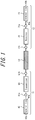
- FIG. 1 is a functional block diagram illustrating the schematic configuration of a high frequency transmission system according to an embodiment of the present disclosure.
- a high frequency transmission system 100 includes two high frequency transmission apparatuses 11 and 12.
- the high frequency transmission apparatuses 11 and 12 are connected electrically to a transmission medium 50.
- one high frequency transmission apparatus 11 transmits a high frequency signal or electric power through the transmission medium 50
- the other high frequency transmission apparatus 12 receives the high frequency signal or electric power through the transmission medium 50.
- the high frequency transmission apparatus 11 on the transmitting side includes a transmitter 60
- the high frequency transmission apparatus 12 on the receiving side includes a receiver 70.
- the high frequency transmission apparatuses 11 and 12 may each include a transceiver that has both a transmitter function and a receiver function. In this case, by the transceiver performing either the transmitter function or the receiver function, the high frequency transmission apparatuses 11 and 12 can respectively perform transmission and reception operations.
- the transmitter 60 includes output terminals 61a and 61b at either end
- the receiver 70 includes input terminals 71a and 71b at either end.
- the transmitter, receiver, and transceiver correspond to the "communication device" of the present disclosure.
- FIG. 2 is a functional block diagram illustrating the schematic configuration of a high frequency transmission apparatus in a high frequency transmission system.
- the high frequency transmission apparatuses 11 and 12 in FIG. 1 are collectively indicated as a high frequency transmission apparatus 10.
- the high frequency transmission apparatus 10 is illustrated as including a transceiver 30 that has a transmitter function and a receiver function.
- the input/output terminal 20a in FIG. 2 corresponds to the output terminal 61a and the input terminal 71a in FIG. 1
- the input/output terminal 20b in FIG. 2 corresponds to the output terminal 61b and the input terminal 71b in FIG. 1 .
- the high frequency transmission apparatus 10 includes the transceiver 30, which includes two input/output terminals 20a and 20b, and a terminal line 40.
- the input/output terminal 20a is connected to the terminal line 40, and the input/output terminal 20b is coupled electrically (hereinafter simply “coupled") to the transmission medium 50, which is formed by a conductor, such as metal, or a dielectric.
- the transceiver 30 includes a transceiver unit 31 that controls transmission and reception operations in the transceiver 30.
- the transceiver 30 transmits a high frequency signal or electric power through the transmission medium 50 to another high frequency transmission apparatus 10 coupled to the transmission medium 50.
- the transceiver 30 When the transceiver 30 functions as a transmitter, current flows to the terminal line 40 from the input/output terminal 20a of the transceiver 30 connected to the terminal line 40. At the same time, current of the same magnitude as the current flowing in the terminal line 40 flows in the opposite direction from the other input/output terminal 20b to the transmission medium 50, and the transceiver 30 transmits a high frequency signal or electric power to the transmission medium 50.
- the transceiver 30 When the transceiver 30 functions as a receiver, current flows from the input/output terminal 20b coupled to the transmission medium 50 into the transceiver 30. At the same time, current of the same magnitude as the current flowing into the transceiver 30 flows in the opposite direction from the terminal line 40 to the other input/output terminal 20a, and the transceiver 30 receives a high frequency signal or electric power from the transmission medium 50.
- the terminal line 40 has an electrical length of 90°.
- An electrical length of 90° means that the length of the line from the end 40a connected to the input/output terminal 20a to the other end 40b is one quarter of the wavelength of the high frequency signal to be transmitted. In other words, the phase of the high frequency signal to be transmitted advances 90° over the length from the end 40a connected to the input/output terminal 20a to the other end 40b.
- the input/output terminal 20a connected to the terminal line 40 can be considered a short-circuit terminal that is virtually connected to ground, and current flows from the input/output terminal 20a to the terminal line 40. Details are provided below with reference to FIG. 4 .
- the transmission medium 50 becomes a medium that transmits a high frequency signal or electric power between transceivers 30.
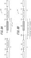
- the transmission medium 50 is configured to include a conductor, a dielectric, or a combination of a conductor and a dielectric. An example of a method for coupling the high frequency transmission apparatus 10 and the transmission medium 50 is described with reference to FIG. 3A, FIG. 3B, and FIG. 3C .
- the transmission medium 50 being a conductor
- coupling of the transmission medium 50 and the input/output terminal 20b of the transceiver 30 is achieved by the input/output terminal 20b touching the transmission medium 50 for conduction.
- the input/output terminal 20b of the transceiver 30 that has the function of a transmitter i.e. the output terminal 61b of the transmitter 60
- the input/output terminal 20b of the transceiver 30 that has the function of a receiver i.e. the input terminal 71b of the receiver 70
- the input/output terminal 20b of the transceiver 30 that has the function of a transmitter i.e. the output terminal 61b of the transmitter 60
- the input/output terminal 20b of the transceiver 30 that has the function of a receiver i.e. the input terminal 71b of the receiver 70
- a high frequency signal or electric power is transmitted through the transmission medium 50 from the transceiver 30 that has the function of a transmitter to the transceiver 30 that has the function of a receiver.
- coupling between the transmission medium 50 and the input/output terminal 20b of the transceiver 30 may, for example as illustrated in FIG. 3B , be achieved by providing a coupling electrode 21 on the input/output terminal 20b of the transceiver 30 and having the coupling electrode 21 and the surface of the transmission medium 50 undergo capacitive coupling when the coupling electrode 21 and the transmission medium 50 come close to each other. In this case, no high frequency signal or electric power is transmitted when the coupling electrode 21 of the transceiver 30 that functions as a transmitter and the coupling electrode 21 of the transceiver 30 that functions as a receiver do not come close to the transmission medium 50.
- a coil may be further provided between the coupling electrode 21 and the input/output terminal 20b of the transceiver 30.
- LC series resonance is generated by the inductance (L) of the coil and the capacitance (C) between the coupling electrode 21 and the surface of the transmission medium 50.
- the transceiver 30 inputs a high frequency signal to the terminal line 40, which has an electrical length of 90°, i.e. one quarter of the wavelength of the high frequency signal to be transmitted, and the end 40b of which is open.
- a standing wave is then generated in the terminal line 40, with maximum voltage amplitude and zero current amplitude at the end 40b and zero voltage amplitude and maximum current amplitude at the end 40a, and current flows to the end 40a. Whereas the voltage amplitude at the end 40a is zero at this time, current flows.
- the end 40a behaves as though it were virtually short circuited to ground.
- the current that flows into the output terminal 61a and the input terminal 71a is maximized when the electrical length of the terminal line 40 is 90°, i.e. when the signal input from the end 40a of the terminal line 40 connected to the output terminal 61a of the transmitter 60 and the input terminal 71a of the receiver 70 is reflected at the other end 40b and returns so that the phase of the reflected wave is 180°. Consequently, the high frequency transmission system 100 operates most effectively when the electrical length of the terminal line 40 is 90°. However, a certain advantage in high frequency transmission is still obtained when the high frequency transmission system 100 operates with the electrical length of the terminal line 40 within a range of ⁇ 45° of 90°, i.e. with the phase of the reflected wave being in a range greater than 90° and smaller than 270°. It thus suffices for the terminal line 40 to have an electrical length of substantially 90°, which includes a range of ⁇ 45° from 90°.
- the structure of the terminal line 40 can be appropriately set in accordance with the frequency of the high frequency signal or electric power.
- the frequency for communicating the high frequency signal or electric power is 13.56 MHz
- the wavelength is approximately 22 m
- the quarter wavelength exceeds 5 m.
- the terminal line 40 may be bent into a meander line structure or a helical structure. The physical length can thus be reduced while maintaining the electrical length of the terminal line 40 at 90°, and the size of the high frequency transmission apparatus 10 can be reduced. Similar effects can also be obtained by attaching a conductor with a large area to the end of the terminal line 40, as illustrated in FIG. 6B , to take advantage of the effect of capacity loading.
- the size can also be reduced by covering the terminal line 40, formed from a conductor, with a material that has a high dielectric constant (high dielectric constant material) 41, as illustrated in FIG. 6C , or forming the terminal line 40 from such high dielectric constant material 41 to take advantage of the effect of wavelength shortening.
- high dielectric constant material 41 high dielectric constant material
- FIG. 7 illustrates the operations of the high frequency transmission apparatus 10 explained in FIG. 5 with reference to the high frequency transmission system 100 of FIG. 1 .
- the output terminal 61a of the transmitter 60 short circuits virtually to ground due to a terminal line 40 that has an electrical length of 90°
- the input terminal 71a of the receiver 70 short circuits virtually to ground due to another terminal line 40 that has an electrical length of 90°, as in the case described with reference to FIG. 5 .
- the output terminal 61b of the transmitter 60 and the input terminal 71b of the receiver 70 are connected through the transmission medium 50.
- the high frequency transmission system 100 is actually an open circuit formed by only one transmission path through one transmission medium 50, the system overall behaves as though it were a closed circuit through a virtual ground, thereby allowing a high frequency signal or electric power to be transmitted stably from the transmitter 60 to the receiver 70.
- the high frequency transmission system 100 provided with a terminal circuit connected to the transmitter 60, the transmitter 60, the receiver 70, and a terminal circuit connected to the receiver can transmit a high frequency signal or electric power from the transmitter 60 to the receiver 70 through one transmission medium 50 over an open circuit formed by only one transmission path.
- the high frequency transmission apparatus 10 transmits a high frequency signal or electric power when coupled to the transmission medium 50 and does not transmit when not coupled. Therefore, a highly stable high frequency transmission system that is easy to design, has a simple configuration, and is not easily affected by the external environment can be provided.
- the system 200 illustrated in FIG. 8A and FIG. 8B includes a high frequency transmission apparatus 13 provided with an identification (ID) circuit 62, which includes an IC chip with embedded ID information, and a high frequency transmission apparatus 14 provided with a reader circuit 72 that reads ID information.
- ID identification
- a terminal line 40 with an electrical length of substantially 90° is connected to one output terminal 61a of the ID circuit 62 and to one input terminal 71a of the reader circuit 72.
- the high frequency transmission apparatuses 13 and 14 are not connected, since the output terminal 61b of the ID circuit 62 is not connected to the transmission medium 50. In this state, the read signal output by the high frequency transmission apparatus 14 is not transmitted to the high frequency transmission apparatus 13, and no signal is transmitted between the high frequency transmission apparatuses 13 and 14.
- the high frequency transmission apparatuses 13 and 14 are connected, since the output terminal 61b of the ID circuit 62 is connected to the transmission medium 50.
- signals are transmitted between the high frequency transmission apparatuses 13 and 14, and a signal including ID information is transmitted from the high frequency transmission apparatus 13 to the high frequency transmission apparatus 14.
- the reader circuit 72 can read the signal that includes ID information. In this way, the reader circuit 72 of the high frequency transmission apparatus 14 can read the ID information, transmitted through the transmission medium 50, of the IC chip.
- the high frequency transmission apparatus 14 may also transmit electric power through the transmission medium 50 along with the read signal.
- the IC chip may operate on the basis of the electric power transmitted along with the read signal and overlay the IC information on the reflected wave of the transmitted signal.
- the reader circuit 72 can read the ID information of the IC chip included in the reflection that is transmitted through the transmission medium 50.
- FIGS. 8A and 8B an example in which the ID circuit 62 and the reader circuit 72 are both connected to the terminal line 40 has been described, but the ID circuit 62 and the reader circuit 72 do not both necessarily have to be connected to the terminal line 40. Communication between the high frequency transmission apparatuses 13 and 14 can be established if one of the ID circuit 62 and the reader circuit 72 is connected to the terminal line 40 and the other is connected to ground.
- FIG. 9 illustrates another specific example of a system using the high frequency transmission system in FIG. 1 .
- the system 300 illustrated in FIG. 9 includes a high frequency transmission apparatus 15 provided with an identification (ID) circuit 62, which includes an IC chip with embedded ID information, and a high frequency transmission apparatus 16 provided with a reader circuit 72 that reads ID information.
- ID identification
- a terminal line 40 with an electrical length of substantially 90° is connected to one output terminal 61a of the ID circuit 62.
- One input terminal 71a of the reader circuit 72 is connected to ground.
- the high frequency transmission apparatuses 15 and 16 are connected once the input terminal 71b of the reader circuit 72 illustrated in FIG. 9 is connected to the transmission medium 50.
- the system 300 overall behaves as a closed circuit through the ground of the high frequency transmission apparatus 16 by the terminal line 40 of the high frequency transmission apparatus 15 functioning as a virtual ground. In this way, by the same principle as described above, communication is established between the high frequency transmission apparatuses 15 and 16.
- the high frequency transmission system 100 can also be used as a human body communication system that uses a human body as a communication medium to establish communication when the human body touches an electrode. Configuring the high frequency transmission system 100 as a human body communication system allows use of the property that communication is possible even when the transmission medium 50 is provided in the high frequency transmission system 100 so as to surround the transceiver.
- a human body communication system that uses a human body as a communication medium
- another transmission path for coupling through space is necessary in addition to the transmission path that passes through the human body as a transmission medium. Consequently, the transmission path through space cannot be established if the transmitter or the receiver is held in the hand or the like, which prevents communication.
- the transmitter and the receiver are connected by one transmission path in the high frequency transmission system 100 according to the present embodiment, communication is possible through a virtual ground, and a closed circuit need not be formed by a second transmission path. Therefore, in the high frequency transmission system 100, communication is possible even if the transmitter or the receiver is completely enclosed by a transmission medium such as a hand.
- the transceivers 30 in the high frequency transmission system 100 can transmit signals through the transmission medium 50 even if one transceiver 30 is covered by the transmission medium.
- the high frequency transmission apparatus 10 can, for example, be embedded in a medical capsule and swallowed. Having the human body that swallowed the medical capsule touch another high frequency transmission apparatus 10 allows communication between the inside and outside of the body, with the body as a communication medium.
- the high frequency transmission system 100 can thus provide a human body communication system that can achieve stable communication.
Landscapes
- Engineering & Computer Science (AREA)
- Computer Networks & Wireless Communication (AREA)
- Signal Processing (AREA)
- Near-Field Transmission Systems (AREA)
- Waveguides (AREA)
Applications Claiming Priority (2)
| Application Number | Priority Date | Filing Date | Title |
|---|---|---|---|
| JP2015216057A JP5935937B1 (ja) | 2015-11-02 | 2015-11-02 | 伝送装置、伝送方法、および伝送システム |
| PCT/JP2016/003015 WO2017077664A1 (ja) | 2015-11-02 | 2016-06-22 | 伝送装置、伝送方法、および伝送システム |
Publications (2)
| Publication Number | Publication Date |
|---|---|
| EP3373483A1 true EP3373483A1 (de) | 2018-09-12 |
| EP3373483A4 EP3373483A4 (de) | 2019-05-15 |
Family
ID=56120567
Family Applications (1)
| Application Number | Title | Priority Date | Filing Date |
|---|---|---|---|
| EP16861742.1A Withdrawn EP3373483A4 (de) | 2015-11-02 | 2016-06-22 | Sendevorrichtung, sendeverfahren und sendesystem |
Country Status (7)
| Country | Link |
|---|---|
| US (1) | US10164718B2 (de) |
| EP (1) | EP3373483A4 (de) |
| JP (1) | JP5935937B1 (de) |
| CN (1) | CN108352905A (de) |
| AU (1) | AU2016350207B2 (de) |
| TW (1) | TW201717555A (de) |
| WO (1) | WO2017077664A1 (de) |
Families Citing this family (1)
| Publication number | Priority date | Publication date | Assignee | Title |
|---|---|---|---|---|
| JP6224862B1 (ja) * | 2017-06-08 | 2017-11-01 | 株式会社eNFC | 接続装置 |
Family Cites Families (18)
| Publication number | Priority date | Publication date | Assignee | Title |
|---|---|---|---|---|
| JP3905418B2 (ja) * | 2001-05-18 | 2007-04-18 | セイコーインスツル株式会社 | 電源装置および電子機器 |
| JP4257611B2 (ja) | 2005-05-17 | 2009-04-22 | ソニー株式会社 | 通信装置および方法、並びにプログラム |
| JP2007089131A (ja) * | 2005-07-25 | 2007-04-05 | Sony Corp | 情報処理装置および方法、プログラム、並びに記録媒体 |
| WO2007070571A2 (en) * | 2005-12-14 | 2007-06-21 | The University Of Kansas | Microstrip antenna for rfid device |
| JP4539551B2 (ja) * | 2005-12-20 | 2010-09-08 | ソニー株式会社 | 情報処理システムおよび方法、情報処理装置および方法、並びにプログラム |
| US8294538B2 (en) * | 2007-03-05 | 2012-10-23 | National University Corporation Kyoto Institute Of Technology | Transmission line microwave apparatus including at least one non-reciprocal transmission line part between two parts |
| JP4605203B2 (ja) * | 2007-10-15 | 2011-01-05 | ソニー株式会社 | 通信システム並びに通信装置 |
| JP2009296551A (ja) * | 2008-06-09 | 2009-12-17 | Sony Corp | 通信システム、音声発生方法、受信装置、および送信装置 |
| JP5166131B2 (ja) * | 2008-06-13 | 2013-03-21 | オンセミコンダクター・トレーディング・リミテッド | 通信システム及びそれに用いられる受信装置 |
| US8058998B2 (en) * | 2008-09-11 | 2011-11-15 | Wistron Neweb Corporation | Elongated twin feed line RFID antenna with distributed radiation perturbations |
| EP2211459A1 (de) * | 2009-01-21 | 2010-07-28 | Sony Corporation | Verstärkungsschaltung mit einer ersten und einer zweiten Ausgabeleitung |
| JP5282626B2 (ja) * | 2009-03-30 | 2013-09-04 | ソニー株式会社 | 通信装置並びに高周波結合器 |
| CA2777731C (fr) * | 2009-10-27 | 2015-12-01 | Sagem Defense Securite | Ensemble d'equipements mettant en oeuvre une transmission de donnees via le corps humain |
| JP5369010B2 (ja) * | 2010-01-25 | 2013-12-18 | パナソニック株式会社 | 通信システム |
| JP5740833B2 (ja) * | 2010-04-20 | 2015-07-01 | ソニー株式会社 | 通信装置及び通信システム |
| AU2011294451B2 (en) | 2010-08-24 | 2016-08-25 | Sony Corporation | Transmitter apparatus, receiver apparatus, and communication system |
| US8994470B2 (en) * | 2011-04-28 | 2015-03-31 | Lenovo Innovations Limited (Hong Kong) | Circuit substrate having noise suppression structure |
| JP2013205361A (ja) * | 2012-03-29 | 2013-10-07 | Toto Ltd | マイクロ波センサ |
-
2015
- 2015-11-02 JP JP2015216057A patent/JP5935937B1/ja active Active
-
2016
- 2016-06-22 WO PCT/JP2016/003015 patent/WO2017077664A1/ja not_active Ceased
- 2016-06-22 CN CN201680053474.XA patent/CN108352905A/zh not_active Withdrawn
- 2016-06-22 US US15/765,028 patent/US10164718B2/en not_active Expired - Fee Related
- 2016-06-22 EP EP16861742.1A patent/EP3373483A4/de not_active Withdrawn
- 2016-06-22 AU AU2016350207A patent/AU2016350207B2/en not_active Ceased
- 2016-10-28 TW TW105134892A patent/TW201717555A/zh unknown
Also Published As
| Publication number | Publication date |
|---|---|
| AU2016350207B2 (en) | 2018-11-29 |
| US20180287716A1 (en) | 2018-10-04 |
| CN108352905A (zh) | 2018-07-31 |
| JP5935937B1 (ja) | 2016-06-15 |
| TW201717555A (zh) | 2017-05-16 |
| US10164718B2 (en) | 2018-12-25 |
| EP3373483A4 (de) | 2019-05-15 |
| WO2017077664A1 (ja) | 2017-05-11 |
| JP2017092539A (ja) | 2017-05-25 |
| AU2016350207A1 (en) | 2018-04-12 |
Similar Documents
| Publication | Publication Date | Title |
|---|---|---|
| CN101187972B (zh) | 通信系统和通信装置 | |
| TWI380614B (de) | ||
| CN102195114B (zh) | 高频耦合器及通信装置 | |
| CN102693034A (zh) | 触摸输入器件和使用其的电磁波收发器 | |
| CN108944495A (zh) | 通过电动车用充电电缆传输能量和信息的装置 | |
| KR20100075353A (ko) | 인체영역 네트워크에서 인체의 일부를 안테나로 이용하는 통신 시스템 및 방법 | |
| GB2519121A (en) | Metering device and parts therefor | |
| CN100563077C (zh) | 电源供应系统及电源供应器 | |
| US10515239B2 (en) | Transmission device and transmission system | |
| US9362622B2 (en) | High-frequency antenna | |
| US10164718B2 (en) | Transmission apparatus, transmission method, and transmission system | |
| US10164719B2 (en) | Transmission apparatus, transmission method, and transmission system | |
| EP3583657A1 (de) | Antenne für eine elektronische vorrichtung | |
| JP2011182279A (ja) | 静電容量検出回路付き電界通信装置 | |
| Washiro | Electric near field communication for identification and payment on wearable devices | |
| KR102942133B1 (ko) | 스타일러스 안테나 | |
| CN108879046A (zh) | 腔体滤波器 | |
| JP2015130607A (ja) | 通信装置 | |
| EP4542350A1 (de) | Stiftantenne | |
| US20200119770A1 (en) | Connection apparatus | |
| JP2016096667A (ja) | 給電通信構造及び給電通信用線路 |
Legal Events
| Date | Code | Title | Description |
|---|---|---|---|
| STAA | Information on the status of an ep patent application or granted ep patent |
Free format text: STATUS: THE INTERNATIONAL PUBLICATION HAS BEEN MADE |
|
| PUAI | Public reference made under article 153(3) epc to a published international application that has entered the european phase |
Free format text: ORIGINAL CODE: 0009012 |
|
| STAA | Information on the status of an ep patent application or granted ep patent |
Free format text: STATUS: REQUEST FOR EXAMINATION WAS MADE |
|
| 17P | Request for examination filed |
Effective date: 20180416 |
|
| AK | Designated contracting states |
Kind code of ref document: A1 Designated state(s): AL AT BE BG CH CY CZ DE DK EE ES FI FR GB GR HR HU IE IS IT LI LT LU LV MC MK MT NL NO PL PT RO RS SE SI SK SM TR |
|
| AX | Request for extension of the european patent |
Extension state: BA ME |
|
| DAV | Request for validation of the european patent (deleted) | ||
| DAX | Request for extension of the european patent (deleted) | ||
| A4 | Supplementary search report drawn up and despatched |
Effective date: 20190417 |
|
| RIC1 | Information provided on ipc code assigned before grant |
Ipc: H04B 5/02 20060101ALI20190411BHEP Ipc: H01P 3/16 20060101ALI20190411BHEP Ipc: H04B 1/04 20060101ALI20190411BHEP Ipc: H04B 13/00 20060101AFI20190411BHEP Ipc: H04B 5/00 20060101ALI20190411BHEP Ipc: H04B 1/3827 20150101ALI20190411BHEP Ipc: H04B 1/02 20060101ALI20190411BHEP |
|
| STAA | Information on the status of an ep patent application or granted ep patent |
Free format text: STATUS: EXAMINATION IS IN PROGRESS |
|
| 17Q | First examination report despatched |
Effective date: 20191114 |
|
| STAA | Information on the status of an ep patent application or granted ep patent |
Free format text: STATUS: THE APPLICATION IS DEEMED TO BE WITHDRAWN |
|
| 18D | Application deemed to be withdrawn |
Effective date: 20200901 |