EP3373258A1 - Money handling machine - Google Patents
Money handling machine Download PDFInfo
- Publication number
- EP3373258A1 EP3373258A1 EP18158646.2A EP18158646A EP3373258A1 EP 3373258 A1 EP3373258 A1 EP 3373258A1 EP 18158646 A EP18158646 A EP 18158646A EP 3373258 A1 EP3373258 A1 EP 3373258A1
- Authority
- EP
- European Patent Office
- Prior art keywords
- money
- unit
- mode
- storing
- feeding
- Prior art date
- Legal status (The legal status is an assumption and is not a legal conclusion. Google has not performed a legal analysis and makes no representation as to the accuracy of the status listed.)
- Granted
Links
Images




Classifications
-
- G—PHYSICS
- G07—CHECKING-DEVICES
- G07D—HANDLING OF COINS OR VALUABLE PAPERS, e.g. TESTING, SORTING BY DENOMINATIONS, COUNTING, DISPENSING, CHANGING OR DEPOSITING
- G07D9/00—Counting coins; Handling of coins not provided for in the other groups of this subclass
-
- G—PHYSICS
- G07—CHECKING-DEVICES
- G07D—HANDLING OF COINS OR VALUABLE PAPERS, e.g. TESTING, SORTING BY DENOMINATIONS, COUNTING, DISPENSING, CHANGING OR DEPOSITING
- G07D11/00—Devices accepting coins; Devices accepting, dispensing, sorting or counting valuable papers
- G07D11/20—Controlling or monitoring the operation of devices; Data handling
- G07D11/24—Managing the inventory of valuable papers
-
- G—PHYSICS
- G07—CHECKING-DEVICES
- G07D—HANDLING OF COINS OR VALUABLE PAPERS, e.g. TESTING, SORTING BY DENOMINATIONS, COUNTING, DISPENSING, CHANGING OR DEPOSITING
- G07D11/00—Devices accepting coins; Devices accepting, dispensing, sorting or counting valuable papers
- G07D11/50—Sorting or counting valuable papers
Definitions
- the present invention relates to a money handling machine that allows depositing and dispensing of money.
- money handling machines that perform handling for depositing/dispensing money including banknotes and coins have been known.
- money handling machines of this type include, e.g., money changing machines installed in retail shops or restaurants and money depositing and dispensing machines installed in financial institutions.
- a typical money handling machine includes a plurality of storing/feeding units allocated in advance for respective denominations, and transports money deposited from a money receiving unit to, and stores the money in a predetermined storing/feeding unit, and feeds the stored money and dispenses the money from a money dispensing unit.
- denomination recognition, authentification and fitness determination of the deposited money are performed, and based on results thereof, the deposited money is sorted and transported to predetermined respective transport destinations (for example, the storing/feeding units, the money dispensing unit or a collection cassette) (for example, Patent Literatures 1 and 2).
- denomination recognition, fitness determination and authentification of money are collectively referred to as "recognition”.
- Money determined as genuine in authentification is referred to as “genuine money” or “genuine note(s)”
- money determined as not genuine (including counterfeit money and suspect money) is referred as “counterfeit money”.
- fit money money determined as fit for recirculation because of being less stained or damaged in fitness determination
- unfit money money determined as unfit for recirculation because of being stained or damaged
- banknotes In the case of banknotes, a banknote determined as genuine, a banknote determined as not genuine, a banknote determined as fit for recirculation and a banknote recognized as unfit for recirculation are also referred to "genuine note”, “counterfeit note”, “fit note” and unfit note”, respectively.
- European Central Bank stipulates that if a deposited banknote is recognized as counterfeit note, the counterfeit note should be taken in the money handling machine and keep the money in the money handling machine to prevent recirculation. (Hereinafter, this stipulation is referred to " ECB regulation”.) In the future, it is expected that an ECB regulation that is similar to the above will also be applied to coins and will be required even in retail markets.
- the money handling machine (coin depositing and dispensing machine) disclosed in Patent Literature 1 is configured so as to, if deposited money is recognized as counterfeit money, return the money to the money dispensing unit as rejected money, and thus, does not comply with the ECB regulation.
- the money handling machine (banknote handling machine) disclosed in Patent Literature 2 is configured so as to, if a deposited banknote is recognized as counterfeit money, prevent the counterfeit money from being returned to the outside of the machine, by, e.g., stopping transport of the counterfeit money at a predetermined position or storing the counterfeit money in a money storage unit (what is called "capture bin") provided in advance for counterfeit money.
- a money storage unit what is called "capture bin”
- the money handling machine disclosed in Patent Literature 2 performs a procedure for recognizing a banknote deposited into the machine. Each time the deposited banknote is recognized as counterfeit money, the machine stops transporting the counterfeit money in the machine. It is unfavorable that the machine stops transporting whenever the machine detects the counterfeit money by the recognition because this causes stagnation delay of money depositing/dispensing operations.
- the machine also, performs a procedure for storing counterfeit money into a money storage unit of the machine.
- the machine needs to comprise the money storage unit for counterfeit money storage separately from the storing/feeding units and this causes an increase in size of the machine.
- Patent Literature 2 can be regarded as having an excessive capability and may be refrained from being introduced.
- counterfeit money handling there can be various regulations that differ depending on countries, regions, markets or clients, other than the ECB regulation, but in the current status, counterfeit money cannot flexibly be handled with a simple machine.
- An object of the present invention is to provide a money handling machine capable of flexibly handling counterfeit money.
- a money handling machine is a machine comprising: a money receiving unit that receives money from an outside of the machine; a transport unit that transports the money deposited from the money receiving unit; a recognition unit that recognizes a denomination and authenticity of the money transported by the transport unit; a plurality of storing/feeding units capable of storing the money and feeding the stored money; a money dispensing unit that dispenses the money fed from the storing/feeding units; and a control unit that controls storing of money in the plurality of storing/feeding units and feeding of money from the plurality of storing/feeding units, wherein a first mode and a second mode are prepared for a depositing/dispensing mode, in the first mode, the plurality of storing/feeding units are allocated for respective denominations, and in the second mode, at least one of the plurality of storing/feeding units is allocated for counterfeit money storage, and wherein the control unit switches the depositing/dispensing mode between the first mode and the second mode, and
- a money handling machine is capable of flexibly handling counterfeit money.
- FIG. 1 is a perspective view illustrating an outer appearance of a coin depositing and dispensing machine 1 according to an embodiment of the present invention.
- FIG. 2 is a side view illustrating an inner configuration of the coin depositing and dispensing machine 1.
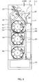
- FIG. 3 is a front view illustrating the inner configuration of the coin depositing and dispensing machine 1.
- FIG. 4 is a block diagram illustrating a configuration of a control system in the coin depositing and dispensing machine 1.
- FIGS. 1 to 4 are used also for description of a coin depositing and dispensing machine 2 according to a second embodiment, which will be described later.
- Depositing handling is handling for counting the number of deposited coins and confirming the amount of the deposited coins.
- Dispensing handling is handling for dispensing coins based on prescribed dispensing information.
- the dispensing information is designated from, for example, an operation/display unit 110 or a higher-ranking machine (external machine). Also, the dispensing information may be an amount to be dispensed or a denomination and number of coins to be dispensed. If the coin depositing and dispensing machine 1 is an automatic change dispenser, dispensing handling includes handling for dispensing change coins.
- dispensing handling includes handling for dispensing exchanged coins.
- Collection handling is handling for collecting coins held inside the machine to the outside of the machine. In collection handling, all of coins held inside the machine may be collected or only a part of coins may be collected. Also, for collection handling, there are a method in which coins are stored in a collection box 70 to collect the coins and a method in which coins are collected from a coin dispensing unit 60.
- the coin depositing and dispensing machine 1 includes, e.g., a coin receiving unit 10, a retaining/feeding unit 20, a deposited money transport unit (transport unit) 30, a plurality of storing/feeding units 40, a dispensed money transport unit 50, the coin dispensing unit 60, the collection box 70, a control unit 100, the operation/display unit 110, a storage unit 120 and a communication unit 130.
- a coin receiving unit 10 e.g., a coin receiving unit 10, a retaining/feeding unit 20, a deposited money transport unit (transport unit) 30, a plurality of storing/feeding units 40, a dispensed money transport unit 50, the coin dispensing unit 60, the collection box 70, a control unit 100, the operation/display unit 110, a storage unit 120 and a communication unit 130.
- the coin receiving unit 10 is disposed in an upper surface of a casing C and includes a coin inlet facing the outside. In depositing handling, coins deposited by a user are received in the machine from the coin receiving unit 10 and sent to the retaining/feeding unit 20 under its own weight.
- the retaining/feeding unit 20 is disposed below the coin receiving unit 10 inside the casing C and temporarily retains the coins deposited in the coin receiving unit 10 and feeds the retained coins one by one to the deposited money transport unit 30.
- the retaining/feeding unit 20 includes a centrifugal disk 21 and a cover member 22.
- the centrifugal disk 21 is disposed so as to be inclined at a predetermined angle relative to a vertical direction and rotates in an inclined position.
- a coin retaining space 23 that retains coins is formed between the centrifugal disk 21 and the cover member 22.
- the deposited money transport unit 30 is disposed above the retaining/feeding unit 20 inside the casing C and transports the coins fed from the retaining/feeding unit 20, one by one.
- the deposited money transport unit 30 includes a first deposited money transport part 30A, a loop-back deposited money transport part 30B and a second deposited money transport part 30C.
- the first deposited money transport part 30A extends along a substantially horizontal direction and transports the coins fed from the retaining/feeding unit 20.
- the loop-back deposited money transport part 30B has a curved shape (here, semi-arc shape) and reverses a direction of the transport of the coins sent from the first deposited money transport part 30A.
- the second deposited money transport part 30C extends along the substantially horizontal direction and transports the coins sent from the loop-back deposited money transport part 30B.
- coins fed from the retaining/feeding unit 20 are transported rightward by the first deposited money transport part 30A, a direction of the transport of the coins is changed by the loop-back deposited money transport part 30B, and the coins are then transported leftward by the second deposited money transport part 30C.
- the deposited money transport unit 30 includes, e.g., a transport belt 31, a recognition unit 32, denomination-based sorting units 33, a rejected money sorting unit 34, chutes 36, a drive motor 37 and tracking sensors 35.
- the transport belt 31 is an endless belt looped around a plurality of pulleys (reference numerals thereof omitted). Along with motion of the drive motor 37 attached to one pulley, the transport belt 31 moves so as to circulate in one direction (counterclockwise in FIG. 2 ).
- the transport belt 31 includes a plurality of projections arranged at equal distances (illustration thereof omitted). One coin is caught by one projection, whereby coins are transported one by one on a surface of the transport belt 31.
- the recognition unit 32 is disposed on the upstream side in the coin transport direction of the denomination-based sorting units 33 and the rejected money sorting unit 34.
- the recognition unit 32 performs recognition and/or detection of deposited coins in terms of denomination, authenticity and fitness. In other words, each of the deposited coins is recognized and/or detected as any of "genuine money”, “suspect money” and “counterfeit money”, by the recognition unit 32. Each of the "genuine money” is further recognized as either of "fit money” and "unfit money”.
- sorting units 33, 34 are referred to as "sorting units 33, 34".
- the denomination-based sorting units 33 are disposed in the first deposited money transport part 30A and the second deposited money transport part 30C. More specifically, three denomination-based sorting units 33 are disposed in the first deposited money transport part 30A, and five denomination-based sorting units 33 are disposed in the second deposited money transport part 30C.
- the denomination-based sorting units 33 sort the deposited coins by denomination, based on results of the recognition of the coins by the recognition unit 32, and send the deposited coins out toward respective storing/feeding units 40 for the respective denominations of the deposited coins via respective chutes 36 provided so as to be continuous with the denomination-based sorting units 33.
- the rejected money sorting unit 34 is disposed on the upstream side in the coin transport direction of the respective denomination-based sorting units 33 in the first deposited money transport part 30A.
- the rejected money sorting unit 34 sorts out rejected coins based on the results of the coin recognition by the recognition unit 32 and sends out the rejected coins toward the coin dispensing unit 60 via a chute 36 provided so as to be continuous with the rejected money sorting unit 34.
- the rejected coins are coins to be subjected to returning handling and are determined based on the results of the recognition by the recognition unit 32.
- the rejected coins can be coins recognized as counterfeit money or suspect money by the recognition unit 32.
- the rejected coins may include unfit money.
- the rejected coins may include coins of a particular denomination the coin depositing and dispensing machine 1 is set not to accept.
- the chutes 36 are provided so as to be continuous with the respective sorting units 33, 34 and causes the coins sent out from the sorting units 33, 34 to slide down.
- the chutes 36 are disposed, for example, on the opposite side of the dispensed money transport unit 50 with reference to the storing/feeding units 40.
- the tracking sensors 35 are disposed in the vicinity on the upstream side in the coin transport direction of the respective denomination-based sorting units 33 and rejected money sorting unit 34.
- Each of the tracking sensors 35 is formed of, for example, an optical sensor and detects passage of a deposited coin. Operations of the denomination-based sorting units 33 and the rejected money sorting unit 34 are controlled based on the results of detection by the tracking sensors 35 (timings of passage of the deposited coins).
- the plurality of storing/feeding units 40 are disposed below the deposited money transport unit 30 inside the casing C.
- eight storing/feeding units 40 are disposed in three tiers in the vertical direction (two in the upper tier, two in the intermediate tier and three in the lower tier).
- the storing/feeding units 40 all have a same configuration. More specifically, each of the storing/feeding units 40 stores coins sent out by the deposited money transport unit 30 via the relevant chute 36, and feeds coins stored therein one by one.
- the storing/feeding units 40 may be arranged in two tiers or four or more tiers in the vertical direction, and the plurality of storing/feeding units 40 may have mutually-different configurations.
- Each of the storing/feeding units 40 includes a centrifugal disk 41 and a cover member 42.
- the centrifugal disk 41 is disposed so as to be inclined at a predetermined angle relative to the vertical direction and rotates in an inclined position.
- a coin storing space 43 that stores coins is formed between the centrifugal disk 41 and the cover member 42.
- a direction of feeding of coins fed from the storing/feeding units 40 is substantially perpendicular to the direction of the transport of coins by the deposited money transport unit 30. More specifically, in FIG. 2 , while the direction of the transport of coins by the deposited money transport unit 30 is a direction parallel to the sheet surface of FIG. 2 , the direction of feeding of coins fed from the storing/feeding units 40 is a direction perpendicular to the sheet surface.
- a first mode and a second mode are prepared and set in a controller 100 for selectable depositing/dispensing modes, and the controller 100 switches between the first mode and the second mode and selects the one mode as the depositing/dispensing mode.
- the storing/feeding units 40 are allocated for the respective denominations.
- the "first mode" is a mode in which normal depositing/dispensing handling is performed.
- the first mode is a mode in which none of the plurality of storing/feeding units 40 is allocated for later-described counterfeit money storage and all of the storing/feeding units 40 can feed coins.
- the first mode for example, one storing/feeding unit 40 is allocated for each of 5-yen coin storage, 50-yen coin storage, 100-yen coin storage and 500-yen coin storage, and two storing/feeding units 40 are allocated for each of 1-yen coin storage and 10-yen coin storage.
- the second mode at least one of the storing/feeding units 40 is allocated for counterfeit money storage.
- the "second mode" is a mode in which if counterfeit money deposited to the machine is detected by the recognition unit 32 in depositing handling, the counterfeit money is kept in the machine and not returned to a depositor to prevent recirculation of the counterfeit money, and is made selectable upon detection of counterfeit money.
- counterfeit money is detected by the recognition unit 32 and the second mode is selected by the controller 30, for example, one of the storing/feeding units 40 for 1-yen coin storage and the storing/feeding units 40 for 10-yen coin storage is allocated for counterfeit money storage.
- the dispensed money transport unit 50 transports coins fed from the respective storing/feeding units 40 to the coin dispensing unit 60.
- the dispensed money transport unit 50 includes a first dispensed money transport part 50A and a second dispensed money transport part 50B (see FIG. 2 ).
- the first dispensed money transport part 50A extends in the substantially horizontal direction below the storing/feeding units 40.
- the second dispensed money transport part 50B transports coins sent from the first dispensed money transport part 50A to the coin dispensing unit 60.
- the dispensed money transport unit 50 includes, e.g., a transport belt 51 and a drive motor (reference numeral thereof omitted).
- the transport belt 51 is an endless belt looped around a plurality of pulleys (reference numerals thereof omitted). Along with motion of the drive motor attached to one pulley, the transport belt 51 moves so as to circulate clockwise or counterclockwise.
- the transport belt 51 includes a plurality of projections (illustration thereof omitted) arranged at equal distances. One coin is caught by one projection, whereby coins are transported one by one on a transport surface.
- Coins fed from the storing/feeding units 40 are sent out toward the side on which the dispensed money transport unit 50 is disposed (right side in FIG. 3 ), drop down onto the transport belt 51 in the first dispensed money transport part 50A and are transported clockwise or counterclockwise.
- the transport belt 51 rotates counterclockwise in FIG. 2 where the coins fed from the storing/feeding units 40 are transported to the coin dispensing unit 60, and rotates clockwise in FIG. 2 where the coins are transported to the collection box 70.
- the coin dispensing unit 60 is disposed in a front surface of the casing C and includes a coin outlet facing the outside. The coins transported by the dispensed money transport unit 50 are dispensed to the coin dispensing unit 60 and removed from the user.
- the coin depositing and dispensing machine 1 may also include a rejection unit for returning rejected coins to the outside of the machine, separately from the coin dispensing unit 60.
- a return outlet of the rejection unit is provided, for example, in the vicinity of the coin outlet.
- the collection box 70 is an auxiliary storage unit disposed below the dispensed money transport unit 50 inside the casing C.
- the collection box 70 is detachably provided in the casing C.
- the collection box 70 is used in collection handling.
- the collection box 70 is used in overflow handling in which coins overflowed from the storing/feeding units 40 are transported to the collection box 70 by the dispensed money transport unit 50. Processing for collecting overflowed coins together with the collection box 70 is also included in collection handling.
- the user removes the collection box 70 from the casing C and can thereby collect collectable coins together with the collection box 70.
- the collection box 70 can also be used for collecting counterfeit money received in the relevant storing/feeding unit 40 in the second mode.
- the control unit 100 includes, e.g., a CPU (central processing unit) 101, which serves as an arithmetic/control unit, a ROM (read-only memory) 102, which is a main memory unit, and a RAM (random access memory) 103.
- the ROM 102 stores a basic program such as a BIOS (basic input/output system) and basic setting data.
- the CPU 101 reads a program according to the content of processing from the ROM 102 or the storage unit 120, develops the program in the RAM 103 and executes the developed program, and thereby performs centralized control of operations of respective blocks in the coin depositing and dispensing machine 1.
- the operation/display unit 110 is formed of, for example, a touch screen-equipped flat panel display.
- a flat panel display e.g., a liquid-crystal display or an organic EL display can be used.
- the operation/display unit 110 is attached, for example, behind the coin receiving unit 10 in the upper surface of the casing C.
- the operation/display unit 110 may be a unit that is separate from the body of the coin depositing and dispensing machine 1 and be connected to the body of the coin depositing and dispensing machine 1 via a wire or wirelessly.
- an operation/display unit of a banknote depositing and dispensing machine or a POS register connected to the coin depositing and dispensing machine 1 may be used as the operation/display unit 110 of the coin depositing and dispensing machine 1.
- the operation/display unit 110 displays information and receives an operation instruction provided by the user, and outputs operation information to the control unit 100. For example, where counterfeit money is detected, the operation/display unit 110 displays, e.g., information relating to handling of the counterfeit money.
- the storage unit 120 is, for example, an auxiliary storage unit such as an HDD (hard disk drive) or an SSD (solid state drive).
- the storage unit 120 stores, e.g., an operating system (OS), a depositing/dispensing processing program and data relating to depositing/dispensing processing.
- OS operating system
- depositing/dispensing processing program data relating to depositing/dispensing processing.
- the depositing/dispensing processing program is provided via, for example, a computer-readable portable storage medium (which includes an optical disk, a magneto-optical disk or a memory card) with the program stored therein.
- the depositing/dispensing processing program may be provided by being downloaded from a server machine (external machine) holding the depositing/dispensing processing program via a network.
- the depositing/dispensing processing program may be stored in the ROM 102.
- Examples of the data relating to depositing/dispensing processing include, e.g., setting data for each storing/feeding unit 40, data on the number of coins of the relevant denomination stored in each storing/feeding unit 40, a flag indicating that the relevant storing/feeding unit 40 is allocated for counterfeit money storage, a flag indicating whether or not coins can be fed from each storing/feeding unit 40 and a flag indicating the depositing/dispensing mode (first mode/second mode).
- Example of the setting data for each storing/feeding unit 40 include, e.g., ID data provided so as to enable identification of the storing/feeding unit 40, location data indicating a location of the storing/feeding unit 40 and data on a denomination allocated to the storing/feeding unit 40.
- the communication unit 130 is, for example, a communication interface such as an NIC (network interface card), a modem (modulator-demodulator) or an USB (universal serial bus).
- the control unit 100 transmits/receives various data to/from an external machine connected to a network such as a wired/wireless LAN, via the communication unit 130.
- a communication interface for short-distance wireless communication such as NFC (near-field communication) or Bluetooth (registered trademark) can also be employed.
- the control unit 100 executes the depositing/dispensing processing program stored in the storage unit 120, and if the recognition unit 32 detects counterfeit money , the control unit 100 guides the counterfeit money to a proper transport destination.
- the depositing/dispensing mode is set to "first mode" in the controller 100 in advance and the controller 100 performs normal depositing/dispensing handling in the first mode.
- the controller 100 automatically switches the depositing/dispensing mode from the first mode to the second mode and performs depositing/dispensing handling in the second mode at least until finishing collection of the counterfeit money.
- the depositing/dispensing mode is switched to a collection mode.
- FIG. 5 is a flowchart illustrating an example of depositing handling according to the first embodiment. This handling is performed, for example, upon the CPU 101 executing the depositing/dispensing handling program stored in the storage unit 120 along with power-on of the coin depositing and dispensing machine 1.
- step S101 the control unit 100 acquires a result of recognition of a deposited coin by the recognition unit 32.
- the control unit 100 can recognize a denomination and authenticity of the deposited coin based on the result of recognition by the recognition unit 32. Also, the control unit 100 may recognize fitness of the deposited coin.
- step S102 the control unit 100 recognizes whether or not the deposited coin is counterfeit money. If the deposited coin is counterfeit money ("YES” in step S102), the processing transitions to the processing in step S103. If the deposited coin is not counterfeit money ("NO” in step S102), that is, if the deposited coin is genuine money regardless of whether or not the deposited coin is fit money or unfit money, the processing transitions to the processing in step S108.
- step S103 the control unit 100 determines whether or not the current depositing/dispensing mode is the first mode. If the current depositing/dispensing mode is the first mode, the processing transitions to the processing in step S104. If the current depositing/dispensing mode is the second mode, that is, if a storing/feeding unit 40 for counterfeit money storage has already been set, the processing transitions to the processing in step S107.
- the storing/feeding unit 40 set for counterfeit money storage is referred to as "capture bin 40CB".
- step S104 the control unit 100 switches the flag indicating the depositing/dispensing mode from the first mode to the second mode.
- step S105 the control unit 100 determines the capture bin 40CB to be allocated for counterfeit money storage from among the plurality of storing/feeding units 40, based on a predetermined condition.
- the predetermined condition is set in advance by, for example, the user performing an operation to select any of a plurality of options on a list displayed on the operation/display unit 110, and is stored in the storage unit 120. Examples of the plurality of options include first to sixth conditions indicated below.
- the first condition is a condition on a distance between the recognition unit 32 and a denomination-based sorting unit 33 (diverter unit) that diverts a coin transported by the deposited money transport unit 30 to a storing/feeding unit 40.
- a storing/feeding unit 40 that stores coins sorted out by a denomination-based sorting unit 33 closest to the recognition unit 32 is set as the capture bin 40CB.
- the second condition is a condition on the denominations allocated to the storing/feeding units 40 in the first mode.
- a storing/feeding unit 40 that stores coins of a largest denomination (here, 500 yen) in the first mode is set as the capture bin 40CB.
- the number of coins of the largest denomination that are fed in dispensing handling is smaller than those of the other denominations.
- the capture bin 40CB is set based on the second condition, coins of the denomination for which the storing/feeding units 40 set as the capture bin 40CB had been allocated are less likely to be needed as coins to be dispensed, and even if counterfeit money is not promptly collected after storing of the counterfeit money, the coin depositing and dispensing machine 1 can tolerate continuing operation. Therefore, setting the capture bin 40CB based on the second condition enables prevention of a decrease in operational efficiency caused as a result of counterfeit money being taken in. Also, in order to more reliably prevent a decrease in operational efficiency, it is preferable that counterfeit money stored in the capture bin 40CB be collected early and the depositing/dispensing mode be returned to the first mode.
- the third condition is a condition on the number of coins stored in each storing/feeding unit 40 at the time of switching to the second mode. More specifically, at the point of time of switching to the second mode, a storing/feeding unit 40 whose number of coins stored therein is largest is set as the capture bin 40CB.
- the storing/feeding unit 40 whose number of coins stored therein is largest is a storing/feeding unit 40 whose number of coins fed therefrom is relatively small. Therefore, if a storing/feeding unit 40 whose number of coins stored therein is largest is set as the capture bin 40CB, as in the case where the capture bin 40CB is set based on the second condition, the stored counterfeit money is less likely to be fed out early. Accordingly, setting the capture bin 40CB based on the third condition enables prevention of a decrease in operational efficiency caused as a result of counterfeit money being taken in. Also, in order to more reliably prevent a decrease in operational efficiency, it is preferable that counterfeit money stored in the capture bin 40CB be collected early and the depositing/dispensing mode be returned to the first mode.
- the fourth condition is a condition on the number of coins stored in a storing/feeding unit 40 at the point of time of switching to the second mode. More specifically, at the point of time of switching to the second mode, a storing/feeding unit 40 whose number of coins stored therein is smallest is set as the capture bin 40CB.
- the capture bin 40CB is a storing/feeding unit 40 whose number of coins stored therein is small and whose number of coins fed therefrom is relatively large in dispensing handling in the first mode.
- coins of the denomination for which the storing/feeding unit 40 set as the capture bin 40CB had been allocated are highly likely to be needed as coins to be dispensed.
- counterfeit money stored in the capture bin 40CB be collected early and the depositing/dispensing mode be returned to the first mode. Furthermore, in order to more reliably prevent a decrease in operational efficiency, it is preferable that after counterfeit money is stored in the capture bin 40CB, the operation be stopped at the point of time of completion of depositing/dispensing handling for money including the counterfeit money and the counterfeit money be collected. Also, for handling for collecting counterfeit money from the capture bin 40CB, it is preferable to employ a method in which coins stored in the capture bin 40CB are transported to the coin dispensing unit 60 and collected.
- the fifth condition is a condition on a location of a storing/feeding unit 40 in the casing C.
- a storing/feeding unit 40 installed at a location that can easily be accessed after opening a door of the casing C is set as the capture bin 40CB.
- a storing/feeding unit 40 installed at a position that can easily be accessed is set as the capture bin 40CB, the capture bin 40CB can easily be accessed. Therefore, setting the capture bin 40CB based on the fifth condition enables collecting only counterfeit money from the capture bin 40CB without collecting all of coins including the counterfeit money and this enables enhancement in efficiency of counterfeit money collection handling. Also, in order to more reliably prevent a decrease in operational efficiency, it is preferable that counterfeit money stored in the capture bin 40CB be collected early and the depositing/dispensing mode be returned to the first mode.
- the sixth condition is a condition on the number of storing/feeding units 40 allocated for a same denomination. For example, if a plurality of storing/feeding units 40 are allocated for a same denomination, one of the plurality of storing/feeding units 40 is set as the capture bin 40CB.
- a timing for collecting counterfeit money is less limited than those of cases where the capture bin 40CB is set based on any of the first to fifth conditions above. Therefore, setting the capture bin 40CB based on the sixth condition enables the user to perform a normal depositing/dispensing operation as in the first mode, with no obstacles to the depositing/dispensing operation caused as a result of counterfeit money being taken in.
- genuine money can be stored in a storing/feeding unit 40 not set as the capture bin 40CB from among the storing/feeding units 40 allocated for the same denomination, and transport of genuine money to the capture bin 40CB can be prohibited, enabling enhancement in efficiency of collecting counterfeit money.
- the first to sixth conditions are prioritized and arbitrarily combined to set the capture bin 40CB.
- the methods for setting the capture bin 40CB are not limited to those described above and may include other types of methods. For example, if a denomination of detected counterfeit money has been recognized, a storing/feeding unit 40 other than a storing/feeding unit 40 allocated for the denomination may be set as the capture bin 40CB. In this case, the user can easily sort out the counterfeit money from coins stored in the capture bin 40CB.
- the control unit 100 controls a notification unit (for example, the operation/display unit 110) to notify the user of the switching of the depositing/dispensing mode to the second mode and the counterfeit money being taken into the machine.
- a notification unit for example, the operation/display unit 110
- notification of, e.g., an ID of the storing/feeding unit 40 set as the capture bin 40CB, a location of the storing/feeding unit 40 and a denomination allocated to the storing/feeding unit 40 may be provided together with the fact that counterfeit money has been taken into the machine. Consequently, the user can become aware of counterfeit money being taken into the machine and can also become aware of a need to perform counterfeit money collection handling.
- a sound output unit or an LED which functions as the notification unit, may be provided in the coin depositing and dispensing machine 1 to provide a notification of counterfeit money being taken into the machine by means of a sound or light emission.
- step S107 the control unit 100 controls the operation of the deposited money transport unit 30 (relevant denomination-based sorting unit 33) according to the second mode to transport the counterfeit money to the capture bin 40CB. Consequently, the counterfeit money is not returned and taken into the machine.
- the counterfeit money taken into the machine is arbitrarily collected, enabling prevention of recirculation of the counterfeit money.
- counterfeit money is not added to a deposited amount, but may be added to a deposited amount in exceptional cases such as a case where a denomination of the counterfeit money is low.
- step S108 the control unit 100 controls the operation of the deposited money transport unit 30 (denomination-based sorting units 33) to transport the deposited coin to a relevant one of the storing/feeding units 40 allocated for the respective denominations or the capture bin 40CB. More specifically, if a deposited coin that is genuine money is received in the first mode and the second mode ("NO" in step S102), the deposited coin is transported to a relevant one of the storing/feeding units 40 allocated for the respective denominations. The denomination allocated in the first mode is still allocated to the storing/feeding unit 40 set as the capture bin 40CB in the second mode. If genuine money is received in the second mode, the genuine money may still be stored even to the storing/feeding unit 40 set as the capture bin 40CB.
- step S103 if counterfeit money is received in the second mode ("NO" in step S103), the counterfeit money is transported to the storing/feeding unit 40 set as the capture bin 40CB.
- the deposited coin may be transported to the storing/feeding unit 40 allocated for the denomination of that coin or may be returned to the coin dispensing unit 60.
- Handling for depositing coins including counterfeit money is performed in such as a manner as described above. The depositing handling is repeated each time a coin is deposited from the coin receiving unit 10.
- the counterfeit money stored in the capture bin 40CB can be collected as follows, for example, at the point of time of completion of depositing/dispensing handling for money including the counterfeit money, the point of time of an end of the depositing/dispensing service (the point of time of the coin depositing and dispensing machine 1 being powered off) or a predetermined timing.
- depositing/dispensing handling where it is necessary to feed coins from the storing/feeding unit 40 allocated for the capture bin 40CB, an instruction to collect the counterfeit money may be provided before feeding coins from the storing/feeding unit 40.
- the coin depositing and dispensing machine 1 shifts to the collection mode for collecting coins.
- control unit 100 may cause, for example, all of coins, including counterfeit money, stored in the capture bin 40CB to be sequentially fed out and dispensed from the coin dispensing unit 60.
- the user can collect the counterfeit money by sorting out the counterfeit money from the dispensed coins.
- control unit 100 may cause all of coins, including counterfeit money, stored in the capture bin 40CB to be sequentially fed out and transported to the collection box 70.
- the user removes the collection box 70 from the coin depositing and dispensing machine 1 and sorts out the counterfeit money from the stored coins, and thereby can collect the counterfeit money.
- overflowed coins may be stored in the collection box 70, and thus, it is preferable that the collection box 70 be changed to a vacant collection box 70 before collection of the counterfeit money and only the coins stored in the capture bin 40CB be collected into the vacant collection box 70.
- the user can collect the counterfeit money directly manually from the capture bin 40CB.
- the coin depositing and dispensing machine 1 Upon, for example, receipt of an end of collection handling from the operation/display unit 110 or the higher-ranking machine (external machine), the coin depositing and dispensing machine 1 transitions to the depositing/dispensing mode. In this case, it is preferable that the coin depositing and dispensing machine 1 newly returns to the first mode, rather than a state before the collection (second mode). Consequently, feeding of coins from the storing/feeding unit 40 allocated to the capture bin 40CB is allowed provided that counterfeit money is collected, that is, no money is stored in the storing/feeding unit 40.
- the coin depositing and dispensing machine 1 (money handling machine) according to the first embodiment includes: the coin receiving unit 10 (money receiving unit) that receives money from the outside of the machine; the deposited money transport unit 30 (transport unit) that transports the money deposited from the money receiving unit 10; the recognition unit 32 that recognizes a denomination and authenticity of the money transported by the deposited money transport unit 30; a plurality of storing/feeding units 40 capable of storing the money and feeding out the money stored therein; the coin dispensing unit 60 (money dispensing unit) that dispenses the money fed from the storing/feeding units 40; and the control unit 100 that controls storing of money in the plurality of storing/feeding units 40 and feeding of money from the plurality of storing/feeding units 40.
- a first mode and a second mode are set for selectable depositing/dispensing modes, in the first mode, the plurality of storing/feeding units (40) are allocated for respective denominations, and in the second mode, at least one of the plurality of storing/feeding units is allocated for counterfeit money storage.
- the control unit 100 controls storing and feeding of money according to a selected one of the first mode and the second mode.
- control unit 100 makes switching from the first mode to the second mode provided that counterfeit money is detected by the recognition unit 32.
- the coin depositing and dispensing machine 1 upon detection of counterfeit money, the first mode is shifted to the second mode, and the counterfeit money is stored in the capture bin 40CB and thereby taken into the machine. A user can prevent recirculation of the counterfeit money by arbitrarily collecting the counterfeit money taken into the machine. Also, according to the coin depositing and dispensing machine 1, there is no need to provide a capture bin 40CB dedicated for counterfeit money, preventing an increase in size of the machine. Furthermore, the coin depositing and dispensing machine 1 can be provided by upgrading a depositing/dispensing handling program without changing a hardware configuration of an existing coin depositing and dispensing machine.
- the coin depositing and dispensing machine 1 can flexibly respond to regulations on handling of counterfeit money such as the ECB regulation (including regulations set by respective providers of the machines). Furthermore, the first mode is automatically switched to the second mode, and thus, a user can perform a depositing/dispensing operation as usual without particularly being aware of counterfeit money being taken into the machine.
- the ECB regulation including regulations set by respective providers of the machines.
- dispensing handling in the first mode feeding of coins from all the storing/feeding units 40 are permitted, and in dispensing handling in the second mode, feeding of coins from the storing/feeding unit 40 allocated for counterfeit money storage (capture bin 40CB) is prohibited, enabling reliable prevention of counterfeit money recirculation.
- a coin depositing and dispensing machine 2 according to a second embodiment has a hardware configuration that is similar to that of the first embodiment.
- the coin depositing and dispensing machine 2 according to the second embodiment is different from that of the first embodiment in installed depositing/dispensing handling program.
- a depositing/dispensing mode is set to "first mode" in advance and the controller 30 performs normal depositing/dispensing handling in the first mode.
- the recognition unit 32 detects counterfeit money
- the depositing/dispensing mode is manually switched from the first mode to a second mode according to an operation rule by the provider of the machine, and depositing/dispensing handling is performed in the second mode until collection of the counterfeit money.
- the depositing/dispensing mode is switched to a collection mode.
- FIG. 6 is a flowchart illustrating an example of depositing/dispensing handling according to the second embodiment. This handling is performed, for example, upon a CPU 101 executing a depositing/dispensing handling program stored in a storage unit 120 along with power-on of the coin depositing and dispensing machine 2. Detailed description of handling that is similar to that in the depositing/dispensing in the first embodiment (flowchart in FIG. 5 ) will be omitted.
- step S201 a control unit 100 acquires a result of a deposited coin by the recognition unit 32.
- step S202 the control unit 100 determines whether or not the deposited coin is counterfeit money. If the deposited coin is counterfeit money ("YES” in step S202), the processing transitions to the processing in step S203. If the deposited coin is not counterfeit money ("NO” in step S202), that is, the deposited coin is genuine money regardless of whether the deposited coin is fit money or unfit money, the processing transitions to the processing in step S212.
- step S203 the control unit 100 determines whether or not the current depositing/dispensing mode is the first mode. If the current depositing/dispensing mode is the first mode ("YES" in step S203), the processing transitions to the processing in step S204. If the current depositing/dispensing mode is the second mode ("NO" in step S203), that is, if the capture bin 40CB has already been set, the processing transitions to the processing in step S211.
- step S204 the control unit 100 controls operation of a deposited money transport unit 30 to stop deposited coin transport.
- the deposited counterfeit money is held between the recognition unit 32 and a denomination-based sorting unit 33 disposed at a most upstream position of the deposited money transport unit 30 in a coin transport direction.
- step S205 the control unit 100 causes an operation/display unit 110 to display a mode switching approval screen.
- the mode switching approval screen for example, indicates that counterfeit money has been detected and displays an approval button for confirming whether or not a user approves a shift from the first mode to the second mode.
- step S206 the control unit 100 receives an approval or a disapproval given by the user via the operation/display unit 110.
- step S207 the control unit 100 determines whether or not a shift to the second mode has been approved by the user. If the shift to the second mode has been approved ("YES” in step S207), the processing transitions to the processing in step S208. If the shift to the second mode has been disapproved (“NO” in step S207), the control unit 100 resumes the coin transport still in the first mode, to transport the coin determined as counterfeit money to a coin dispensing unit 60 and return the coin (step S213).
- step S208 the control unit 100 switches a flag indicating the depositing/dispensing mode from the first mode to the second mode.
- step S209 the control unit 100 determines a capture bin 40CB to be allocated for counterfeit money storage from among a plurality of storing/feeding units 40, based on a predetermined condition.
- the capture bin 40CB is set in a manner that is similar to that in the first embodiment.
- step S210 the control unit 100 notifies the user of the switching of the depositing/dispensing mode to the second mode and counterfeit money being taken in.
- step S211 the control unit 100 controls the operation of the deposited money transport unit 30 (denomination-based sorting units 33) according to the second mode to resume the coin transport and thereby transport the counterfeit money to the capture bin 40CB. Consequently, the counterfeit money is not returned and is taken into the machine.
- the counterfeit money taken into the machine is arbitrarily collected, enabling prevention of recirculation of the counterfeit money.
- counterfeit money is not included in the amount of deposited money, but may be included in the amount of deposited money in exceptional cases such as a case where the denomination of the counterfeit money is low.
- step S212 the control unit 100 controls the operation of the deposited money transport unit 30 (denomination-based sorting units 33) to transport the deposited coin to a relevant one of the storing/feeding units 40 allocated for respective denominations or the capture bin 40CB. More specifically, if a deposited coin that is genuine money is received in the first mode and the second mode ("NO" in step S202), the deposited coin is transported to a relevant one of the storing/feeding units 40 allocated for the respective denominations. The denomination allocated in the first mode is still allocated to the storing/feeding unit 40 set as the capture bin 40CB in the second mode. If genuine money is received in the second mode, genuine money may still be stored even to the storing/feeding unit 40 set as the capture bin 40CB.
- step S202 if counterfeit money is received in the second mode ("NO" in step S202), the counterfeit money is transported to the storing/feeding unit 40 set as the capture bin 40CB.
- the deposited coin may be transported to the storing/feeding unit 40 allocated for the denomination of the deposited coin or may be returned to the coin dispensing unit 60.
- the counterfeit money stored in the capture bin 40CB is arbitrarily collected.
- the coin depositing and dispensing machine 2 (money handling machine) according to the second embodiment includes: the coin receiving unit 10 (money receiving unit) that receives money from the outside of the machine; the deposited money transport unit 30 (transport unit) that transports the money deposited from the money receiving unit 10; a recognition unit 32 that recognizes a denomination and authenticity of the money transported by the deposited money transport unit 30; the plurality of storing/feeding units 40 capable of storing the money and feeding the stored money; the coin dispensing unit 60 (money dispensing unit) that dispenses the money fed from the storing/feeding units 40; and the control unit 100 that controls storing of money in the plurality of storing/feeding units 40 and feeding of money from the plurality of storing/feeding units 40.
- a first mode and a second mode are set for selectable depositing/dispensing modes, in the first mode, the plurality of storing/feeding units (40) are allocated for respective denominations, and in the second mode, at least one of the plurality of storing/feeding units is allocated for counterfeit money storage.
- the control unit 100 controls the storing and the feeding of money according to a mode selected from the first mode and the second mode.
- the coin depositing and dispensing machine 2 further includes the operation/display unit 110 (a notification unit and an input unit) that provides a notification that the recognition unit 32 has detected counterfeit money and receives an instruction to select the first mode or the second mode.
- the control unit 100 makes switching from the first mode to the second mode based on an input from the operation/display unit 110, which serves as the input unit.
- the coin depositing and dispensing machine 2 upon detection of counterfeit money and approval of a shift from the first mode to the second mode, the counterfeit money is stored in the capture bin 40CB and thereby taken into the machine. A user arbitrarily collects the counterfeit money taken into the machine, enabling prevention of recirculation of the counterfeit money. Also, the coin depositing and dispensing machine 2 eliminates the need for providing a dedicated capture bin 40CB for counterfeit money and this prevents an increase in size of the machine. Furthermore, the coin depositing and dispensing machine 2 can be provided by upgrading a depositing/dispensing handling program without changing a hardware configuration of an existing coin depositing and dispensing machine.
- the coin depositing and dispensing machine 2 can flexibly respond to regulations on handling of counterfeit money such as the ECB regulation (including regulations set by respective providers of the machines). Furthermore, if there is no strict regulation on handling of counterfeit money like the ECB regulation, operations according to respective providers of the machines are possible. For example, an operation in which counterfeit money of a low denomination is returned and counterfeit money of a high denomination is taken into the machine is possible.
- the ECB regulation including regulations set by respective providers of the machines.
- control unit 100 permits feeding of coins from all of the storing/feeding units 40 in the first mode and prohibits feeding of coins from the storing/feeding unit 40 (capture bin 40CB) allocated for counterfeit money storage in dispensing handling in the second mode
- feeding of coins from the capture bin 40CB may be permitted if a predetermined condition is met in dispensing handling in the second mode.
- the predetermined condition is, for example, that prevention of feeding of counterfeit money from the capture bin 40CB is ensured.
- the storing/feeding units 40 are each configured so as to feed coins in the order the coins are stored, and may permit feeding of coins from the storing/feeding unit 40 (capture bin 40CB) if genuine money has already been stored before detection of counterfeit money to the extent that genuine money stored before the detection of counterfeit money is fed out. Consequently, in the second mode, even if counterfeit money is not collected immediately after storing of the counterfeit money in the capture bin 40C, the operation can be continued as it is for some time, enabling prevention in a decrease in operational efficiency. In this case, also, in order to prevent a decrease in operational efficiency, it is preferable that the counterfeit money stored in the capture bin 40CB be collected early and the depositing/dispensing mode be returned to the first mode.
- FIG. 7A is a side view schematically illustrating a depositing/dispensing path in the coin depositing and dispensing machine 3
- FIG. 7B is a flat view schematically illustrating a dispensing path in the coin depositing and dispensing machine 3.
- the coin depositing and dispensing machine 3 illustrated in FIGS. 7A and 7B includes: a coin receiving unit 10 disposed at an upper portion of the machine; a deposited money transport unit 30 disposed below the coin receiving unit 10, the deposited money transport unit 30 including a recognition unit 32 and a denomination-based sorting unit 33; a dispensed money transport unit 50 disposed below the deposited money transport unit 30, the dispensed money transport unit 50 extending linearly; and storing/feeding units 40, four of which are arranged on each of opposite sides along a direction in which the dispensed money transport unit 50 extends.
- Each of the storing/feeding units 40 is a coin storing/feeding unit having a horizontally-disposed rotary disk. In such coin depositing and dispensing machine 3, depositing/dispensing handling is performed in a manner that is substantially similar to those in the embodiments.
- the present invention is applicable not only to a coin depositing and dispensing machine but also to a banknote depositing and dispensing machine that performs banknote depositing/dispensing handling.
- a banknote depositing/dispensing handling machine has, for example, the configuration disclosed in Japanese Patent Application Laid-Open No. 2012-203666 .
- the present invention can be provided by upgrading a depositing/dispensing handling program in a known banknote depositing and dispensing machine, and thus, description of a detailed configuration of the banknote depositing/dispensing handling machine will be omitted.
- the present invention is applicable not only to a depositing and dispensing machine that handles coins or banknotes, but also to an automatic change dispenser or a money changer.
Landscapes
- Physics & Mathematics (AREA)
- General Physics & Mathematics (AREA)
- Cash Registers Or Receiving Machines (AREA)
Abstract
Description
- The present invention relates to a money handling machine that allows depositing and dispensing of money.
- Conventionally, money handling machines that perform handling for depositing/dispensing money including banknotes and coins have been known. Examples of money handling machines of this type include, e.g., money changing machines installed in retail shops or restaurants and money depositing and dispensing machines installed in financial institutions.
- A typical money handling machine includes a plurality of storing/feeding units allocated in advance for respective denominations, and transports money deposited from a money receiving unit to, and stores the money in a predetermined storing/feeding unit, and feeds the stored money and dispenses the money from a money dispensing unit. In the money handling machine, in the process of transporting deposited money from the money receiving unit to the storing/feeding units, denomination recognition, authentification and fitness determination of the deposited money are performed, and based on results thereof, the deposited money is sorted and transported to predetermined respective transport destinations (for example, the storing/feeding units, the money dispensing unit or a collection cassette) (for example, Patent Literatures 1 and 2).
- In the below, denomination recognition, fitness determination and authentification of money are collectively referred to as "recognition". Money determined as genuine in authentification is referred to as "genuine money" or "genuine note(s)", and money determined as not genuine (including counterfeit money and suspect money) is referred as "counterfeit money". Also, from among genuine money, money determined as fit for recirculation because of being less stained or damaged in fitness determination is referred to as "fit money", and money determined as unfit for recirculation because of being stained or damaged is referred to as "unfit money". In the case of banknotes, a banknote determined as genuine, a banknote determined as not genuine, a banknote determined as fit for recirculation and a banknote recognized as unfit for recirculation are also referred to "genuine note", "counterfeit note", "fit note" and unfit note", respectively.
- In European financial markets, European Central Bank (ECB) stipulates that if a deposited banknote is recognized as counterfeit note, the counterfeit note should be taken in the money handling machine and keep the money in the money handling machine to prevent recirculation. (Hereinafter, this stipulation is referred to " ECB regulation".) In the future, it is expected that an ECB regulation that is similar to the above will also be applied to coins and will be required even in retail markets.
- However, the money handling machine (coin depositing and dispensing machine) disclosed in Patent Literature 1 is configured so as to, if deposited money is recognized as counterfeit money, return the money to the money dispensing unit as rejected money, and thus, does not comply with the ECB regulation.
- On the other hand, the money handling machine (banknote handling machine) disclosed in Patent Literature 2 is configured so as to, if a deposited banknote is recognized as counterfeit money, prevent the counterfeit money from being returned to the outside of the machine, by, e.g., stopping transport of the counterfeit money at a predetermined position or storing the counterfeit money in a money storage unit (what is called "capture bin") provided in advance for counterfeit money. In other words, an operation complying with the ECB regulation is possible in the money handling machine disclosed in Patent Literature 2.
-
- PTL 1
Japanese Patent Application Laid-Open No.2012-174039 - PTL 2
Japanese Patent Application Laid-Open No.2012-203666 - The money handling machine disclosed in Patent Literature 2, for example, performs a procedure for recognizing a banknote deposited into the machine. Each time the deposited banknote is recognized as counterfeit money, the machine stops transporting the counterfeit money in the machine. It is unfavorable that the machine stops transporting whenever the machine detects the counterfeit money by the recognition because this causes stagnation delay of money depositing/dispensing operations. The machine, also, performs a procedure for storing counterfeit money into a money storage unit of the machine. The machine needs to comprise the money storage unit for counterfeit money storage separately from the storing/feeding units and this causes an increase in size of the machine. Furthermore, as in current retail markets or financial markets in regions other than Europe, where recirculation of counterfeit money is not particularly prohibited and handling of counterfeit money is left up to the provider of the machine, the money handling machine disclosed in Patent Literature 2 can be regarded as having an excessive capability and may be refrained from being introduced. For counterfeit money handling, there can be various regulations that differ depending on countries, regions, markets or clients, other than the ECB regulation, but in the current status, counterfeit money cannot flexibly be handled with a simple machine.
- An object of the present invention is to provide a money handling machine capable of flexibly handling counterfeit money.
- A money handling machine according to the present invention is a machine comprising: a money receiving unit that receives money from an outside of the machine; a transport unit that transports the money deposited from the money receiving unit; a recognition unit that recognizes a denomination and authenticity of the money transported by the transport unit; a plurality of storing/feeding units capable of storing the money and feeding the stored money; a money dispensing unit that dispenses the money fed from the storing/feeding units; and a control unit that controls storing of money in the plurality of storing/feeding units and feeding of money from the plurality of storing/feeding units, wherein a first mode and a second mode are prepared for a depositing/dispensing mode, in the first mode, the plurality of storing/feeding units are allocated for respective denominations, and in the second mode, at least one of the plurality of storing/feeding units is allocated for counterfeit money storage, and wherein the control unit switches the depositing/dispensing mode between the first mode and the second mode, and controls the storing and the feeding of money according to the mode resulting from the switching.
- A money handling machine according to the present invention is capable of flexibly handling counterfeit money.
-
-
FIG. 1 is a perspective view illustrating an outer appearance of a coin depositing and dispensing machine according to an embodiment of the present invention; -
FIG. 2 is a side view illustrating an inner configuration of the coin depositing and dispensing machine illustrated inFIG. 1 ; -
FIG. 3 is a front view illustrating the inner configuration of the coin depositing and dispensing machine illustrated inFIG. 1 ; -
FIG. 4 is a block diagram illustrating a configuration of a control system in the coin depositing and dispensing machine illustrated inFIG. 1 ; -
FIG. 5 is a flowchart illustrating an example of depositing/dispensing handling according to a first embodiment; -
FIG. 6 is a flowchart illustrating an example of depositing/dispensing handling according to a second embodiment; and -
FIGS. 7A is a side view and a plan view illustrating another example money handling machine. -
FIGS. 7B is a side view and a plan view illustrating another example money handling machine. - Embodiments of the present invention will be described in detail below with reference to the accompanying drawings.
-
FIG. 1 is a perspective view illustrating an outer appearance of a coin depositing and dispensing machine 1 according to an embodiment of the present invention.FIG. 2 is a side view illustrating an inner configuration of the coin depositing and dispensing machine 1.FIG. 3 is a front view illustrating the inner configuration of the coin depositing and dispensing machine 1.FIG. 4 is a block diagram illustrating a configuration of a control system in the coin depositing and dispensing machine 1.FIGS. 1 to 4 are used also for description of a coin depositing and dispensing machine 2 according to a second embodiment, which will be described later. - First, depositing handling, dispensing handling and collection handling in the coin depositing and dispensing machine 1 will briefly be described. Depositing handling is handling for counting the number of deposited coins and confirming the amount of the deposited coins. Dispensing handling is handling for dispensing coins based on prescribed dispensing information. The dispensing information is designated from, for example, an operation/
display unit 110 or a higher-ranking machine (external machine). Also, the dispensing information may be an amount to be dispensed or a denomination and number of coins to be dispensed. If the coin depositing and dispensing machine 1 is an automatic change dispenser, dispensing handling includes handling for dispensing change coins. Also, if the coin depositing and dispensing machine 1 is a money changing machine, dispensing handling includes handling for dispensing exchanged coins. Collection handling is handling for collecting coins held inside the machine to the outside of the machine. In collection handling, all of coins held inside the machine may be collected or only a part of coins may be collected. Also, for collection handling, there are a method in which coins are stored in acollection box 70 to collect the coins and a method in which coins are collected from acoin dispensing unit 60. - As illustrated in
FIGS. 1 to 4 , the coin depositing and dispensing machine 1 includes, e.g., acoin receiving unit 10, a retaining/feeding unit 20, a deposited money transport unit (transport unit) 30, a plurality of storing/feeding units 40, a dispensedmoney transport unit 50, thecoin dispensing unit 60, thecollection box 70, acontrol unit 100, the operation/display unit 110, astorage unit 120 and acommunication unit 130. - The
coin receiving unit 10 is disposed in an upper surface of a casing C and includes a coin inlet facing the outside. In depositing handling, coins deposited by a user are received in the machine from thecoin receiving unit 10 and sent to the retaining/feeding unit 20 under its own weight. - The retaining/
feeding unit 20 is disposed below thecoin receiving unit 10 inside the casing C and temporarily retains the coins deposited in thecoin receiving unit 10 and feeds the retained coins one by one to the depositedmoney transport unit 30. The retaining/feeding unit 20 includes acentrifugal disk 21 and acover member 22. Thecentrifugal disk 21 is disposed so as to be inclined at a predetermined angle relative to a vertical direction and rotates in an inclined position. Acoin retaining space 23 that retains coins is formed between thecentrifugal disk 21 and thecover member 22. - The deposited
money transport unit 30 is disposed above the retaining/feeding unit 20 inside the casing C and transports the coins fed from the retaining/feeding unit 20, one by one. The depositedmoney transport unit 30 includes a first depositedmoney transport part 30A, a loop-back depositedmoney transport part 30B and a second deposited money transport part 30C. The first depositedmoney transport part 30A extends along a substantially horizontal direction and transports the coins fed from the retaining/feeding unit 20. The loop-back depositedmoney transport part 30B has a curved shape (here, semi-arc shape) and reverses a direction of the transport of the coins sent from the first depositedmoney transport part 30A. The second deposited money transport part 30C extends along the substantially horizontal direction and transports the coins sent from the loop-back depositedmoney transport part 30B. InFIG. 2 , coins fed from the retaining/feeding unit 20 are transported rightward by the first depositedmoney transport part 30A, a direction of the transport of the coins is changed by the loop-back depositedmoney transport part 30B, and the coins are then transported leftward by the second deposited money transport part 30C. - The deposited
money transport unit 30 includes, e.g., atransport belt 31, arecognition unit 32, denomination-basedsorting units 33, a rejectedmoney sorting unit 34,chutes 36, adrive motor 37 and trackingsensors 35. - The
transport belt 31 is an endless belt looped around a plurality of pulleys (reference numerals thereof omitted). Along with motion of thedrive motor 37 attached to one pulley, thetransport belt 31 moves so as to circulate in one direction (counterclockwise inFIG. 2 ). Thetransport belt 31 includes a plurality of projections arranged at equal distances (illustration thereof omitted). One coin is caught by one projection, whereby coins are transported one by one on a surface of thetransport belt 31. - The
recognition unit 32 is disposed on the upstream side in the coin transport direction of the denomination-basedsorting units 33 and the rejectedmoney sorting unit 34. Therecognition unit 32 performs recognition and/or detection of deposited coins in terms of denomination, authenticity and fitness. In other words, each of the deposited coins is recognized and/or detected as any of "genuine money", "suspect money" and "counterfeit money", by therecognition unit 32. Each of the "genuine money" is further recognized as either of "fit money" and "unfit money". In the below, where the denomination-basedsorting units 33 and the rejectedmoney sorting unit 34 are not distinguished from each other, the denomination-basedsorting units 33 and the rejectedmoney sorting unit 34 are referred to as "sortingunits - The denomination-based
sorting units 33 are disposed in the first depositedmoney transport part 30A and the second deposited money transport part 30C. More specifically, three denomination-basedsorting units 33 are disposed in the first depositedmoney transport part 30A, and five denomination-basedsorting units 33 are disposed in the second deposited money transport part 30C. The denomination-basedsorting units 33 sort the deposited coins by denomination, based on results of the recognition of the coins by therecognition unit 32, and send the deposited coins out toward respective storing/feeding units 40 for the respective denominations of the deposited coins viarespective chutes 36 provided so as to be continuous with the denomination-basedsorting units 33. - The rejected
money sorting unit 34 is disposed on the upstream side in the coin transport direction of the respective denomination-basedsorting units 33 in the first depositedmoney transport part 30A. The rejectedmoney sorting unit 34 sorts out rejected coins based on the results of the coin recognition by therecognition unit 32 and sends out the rejected coins toward thecoin dispensing unit 60 via achute 36 provided so as to be continuous with the rejectedmoney sorting unit 34. The rejected coins are coins to be subjected to returning handling and are determined based on the results of the recognition by therecognition unit 32. For example, the rejected coins can be coins recognized as counterfeit money or suspect money by therecognition unit 32. Also, the rejected coins may include unfit money. Also, the rejected coins may include coins of a particular denomination the coin depositing and dispensing machine 1 is set not to accept. - The
chutes 36 are provided so as to be continuous with therespective sorting units units chutes 36 are disposed, for example, on the opposite side of the dispensedmoney transport unit 50 with reference to the storing/feeding units 40. - The tracking
sensors 35 are disposed in the vicinity on the upstream side in the coin transport direction of the respective denomination-basedsorting units 33 and rejectedmoney sorting unit 34. Each of the trackingsensors 35 is formed of, for example, an optical sensor and detects passage of a deposited coin. Operations of the denomination-basedsorting units 33 and the rejectedmoney sorting unit 34 are controlled based on the results of detection by the tracking sensors 35 (timings of passage of the deposited coins). - The plurality of storing/
feeding units 40 are disposed below the depositedmoney transport unit 30 inside the casing C. In the present embodiment, eight storing/feeding units 40 are disposed in three tiers in the vertical direction (two in the upper tier, two in the intermediate tier and three in the lower tier). The storing/feeding units 40 all have a same configuration. More specifically, each of the storing/feeding units 40 stores coins sent out by the depositedmoney transport unit 30 via therelevant chute 36, and feeds coins stored therein one by one. Here, the storing/feeding units 40 may be arranged in two tiers or four or more tiers in the vertical direction, and the plurality of storing/feeding units 40 may have mutually-different configurations. - Each of the storing/
feeding units 40 includes acentrifugal disk 41 and acover member 42. Thecentrifugal disk 41 is disposed so as to be inclined at a predetermined angle relative to the vertical direction and rotates in an inclined position. Acoin storing space 43 that stores coins is formed between thecentrifugal disk 41 and thecover member 42. - A direction of feeding of coins fed from the storing/
feeding units 40 is substantially perpendicular to the direction of the transport of coins by the depositedmoney transport unit 30. More specifically, inFIG. 2 , while the direction of the transport of coins by the depositedmoney transport unit 30 is a direction parallel to the sheet surface ofFIG. 2 , the direction of feeding of coins fed from the storing/feeding units 40 is a direction perpendicular to the sheet surface. - A first mode and a second mode are prepared and set in a
controller 100 for selectable depositing/dispensing modes, and thecontroller 100 switches between the first mode and the second mode and selects the one mode as the depositing/dispensing mode. In the first mode, the storing/feeding units 40 are allocated for the respective denominations. The "first mode" is a mode in which normal depositing/dispensing handling is performed. In other words, the first mode is a mode in which none of the plurality of storing/feeding units 40 is allocated for later-described counterfeit money storage and all of the storing/feeding units 40 can feed coins. In the first mode, for example, one storing/feeding unit 40 is allocated for each of 5-yen coin storage, 50-yen coin storage, 100-yen coin storage and 500-yen coin storage, and two storing/feeding units 40 are allocated for each of 1-yen coin storage and 10-yen coin storage. On the other hand, in the second mode, at least one of the storing/feeding units 40 is allocated for counterfeit money storage. The "second mode" is a mode in which if counterfeit money deposited to the machine is detected by therecognition unit 32 in depositing handling, the counterfeit money is kept in the machine and not returned to a depositor to prevent recirculation of the counterfeit money, and is made selectable upon detection of counterfeit money. - If counterfeit money is detected by the
recognition unit 32 and the second mode is selected by thecontroller 30, for example, one of the storing/feeding units 40 for 1-yen coin storage and the storing/feeding units 40 for 10-yen coin storage is allocated for counterfeit money storage. - In dispensing handling or collection handling, the dispensed
money transport unit 50 transports coins fed from the respective storing/feeding units 40 to thecoin dispensing unit 60. The dispensedmoney transport unit 50 includes a first dispensedmoney transport part 50A and a second dispensedmoney transport part 50B (seeFIG. 2 ). The first dispensedmoney transport part 50A extends in the substantially horizontal direction below the storing/feeding units 40. The second dispensedmoney transport part 50B transports coins sent from the first dispensedmoney transport part 50A to thecoin dispensing unit 60. - The dispensed
money transport unit 50 includes, e.g., atransport belt 51 and a drive motor (reference numeral thereof omitted). Thetransport belt 51 is an endless belt looped around a plurality of pulleys (reference numerals thereof omitted). Along with motion of the drive motor attached to one pulley, thetransport belt 51 moves so as to circulate clockwise or counterclockwise. Thetransport belt 51 includes a plurality of projections (illustration thereof omitted) arranged at equal distances. One coin is caught by one projection, whereby coins are transported one by one on a transport surface. - Coins fed from the storing/
feeding units 40 are sent out toward the side on which the dispensedmoney transport unit 50 is disposed (right side inFIG. 3 ), drop down onto thetransport belt 51 in the first dispensedmoney transport part 50A and are transported clockwise or counterclockwise. For example, thetransport belt 51 rotates counterclockwise inFIG. 2 where the coins fed from the storing/feeding units 40 are transported to thecoin dispensing unit 60, and rotates clockwise inFIG. 2 where the coins are transported to thecollection box 70. - The
coin dispensing unit 60 is disposed in a front surface of the casing C and includes a coin outlet facing the outside. The coins transported by the dispensedmoney transport unit 50 are dispensed to thecoin dispensing unit 60 and removed from the user. - Here, the coin depositing and dispensing machine 1 may also include a rejection unit for returning rejected coins to the outside of the machine, separately from the
coin dispensing unit 60. A return outlet of the rejection unit is provided, for example, in the vicinity of the coin outlet. - The
collection box 70 is an auxiliary storage unit disposed below the dispensedmoney transport unit 50 inside the casing C. Thecollection box 70 is detachably provided in the casing C. Thecollection box 70 is used in collection handling. Also, thecollection box 70 is used in overflow handling in which coins overflowed from the storing/feeding units 40 are transported to thecollection box 70 by the dispensedmoney transport unit 50. Processing for collecting overflowed coins together with thecollection box 70 is also included in collection handling. The user removes thecollection box 70 from the casing C and can thereby collect collectable coins together with thecollection box 70. Thecollection box 70 can also be used for collecting counterfeit money received in the relevant storing/feeding unit 40 in the second mode. - The
control unit 100 includes, e.g., a CPU (central processing unit) 101, which serves as an arithmetic/control unit, a ROM (read-only memory) 102, which is a main memory unit, and a RAM (random access memory) 103. TheROM 102 stores a basic program such as a BIOS (basic input/output system) and basic setting data. TheCPU 101 reads a program according to the content of processing from theROM 102 or thestorage unit 120, develops the program in theRAM 103 and executes the developed program, and thereby performs centralized control of operations of respective blocks in the coin depositing and dispensing machine 1. - The operation/
display unit 110 is formed of, for example, a touch screen-equipped flat panel display. For the flat panel display, e.g., a liquid-crystal display or an organic EL display can be used. Although not illustrated inFIG. 1 , the operation/display unit 110 is attached, for example, behind thecoin receiving unit 10 in the upper surface of the casing C. Also, the operation/display unit 110 may be a unit that is separate from the body of the coin depositing and dispensing machine 1 and be connected to the body of the coin depositing and dispensing machine 1 via a wire or wirelessly. Also, an operation/display unit of a banknote depositing and dispensing machine or a POS register connected to the coin depositing and dispensing machine 1 may be used as the operation/display unit 110 of the coin depositing and dispensing machine 1. The operation/display unit 110 displays information and receives an operation instruction provided by the user, and outputs operation information to thecontrol unit 100. For example, where counterfeit money is detected, the operation/display unit 110 displays, e.g., information relating to handling of the counterfeit money. - The
storage unit 120 is, for example, an auxiliary storage unit such as an HDD (hard disk drive) or an SSD (solid state drive). Thestorage unit 120 stores, e.g., an operating system (OS), a depositing/dispensing processing program and data relating to depositing/dispensing processing. - The depositing/dispensing processing program is provided via, for example, a computer-readable portable storage medium (which includes an optical disk, a magneto-optical disk or a memory card) with the program stored therein. Also, for example, the depositing/dispensing processing program may be provided by being downloaded from a server machine (external machine) holding the depositing/dispensing processing program via a network. Also, the depositing/dispensing processing program may be stored in the
ROM 102. - Examples of the data relating to depositing/dispensing processing include, e.g., setting data for each storing/
feeding unit 40, data on the number of coins of the relevant denomination stored in each storing/feeding unit 40, a flag indicating that the relevant storing/feeding unit 40 is allocated for counterfeit money storage, a flag indicating whether or not coins can be fed from each storing/feedingunit 40 and a flag indicating the depositing/dispensing mode (first mode/second mode). Example of the setting data for each storing/feeding unit 40 include, e.g., ID data provided so as to enable identification of the storing/feeding unit 40, location data indicating a location of the storing/feeding unit 40 and data on a denomination allocated to the storing/feeding unit 40. - The
communication unit 130 is, for example, a communication interface such as an NIC (network interface card), a modem (modulator-demodulator) or an USB (universal serial bus). Thecontrol unit 100 transmits/receives various data to/from an external machine connected to a network such as a wired/wireless LAN, via thecommunication unit 130. For thecommunication unit 130, a communication interface for short-distance wireless communication such as NFC (near-field communication) or Bluetooth (registered trademark) can also be employed. - The
control unit 100 executes the depositing/dispensing processing program stored in thestorage unit 120, and if therecognition unit 32 detects counterfeit money , thecontrol unit 100 guides the counterfeit money to a proper transport destination. In the first embodiment, when the coin depositing and dispensing machine 1 is started up, the depositing/dispensing mode is set to "first mode" in thecontroller 100 in advance and thecontroller 100 performs normal depositing/dispensing handling in the first mode. And when therecognition unit 32 detects counterfeit money during execution of the depositing/dispensing processing program, thecontroller 100 automatically switches the depositing/dispensing mode from the first mode to the second mode and performs depositing/dispensing handling in the second mode at least until finishing collection of the counterfeit money. Also, during collection of coins (which means that at the time from starting to finishing collecting the counterfeit money into a storing/feeding unit 40 for counterfeit money storage), the depositing/dispensing mode is switched to a collection mode. -
FIG. 5 is a flowchart illustrating an example of depositing handling according to the first embodiment. This handling is performed, for example, upon theCPU 101 executing the depositing/dispensing handling program stored in thestorage unit 120 along with power-on of the coin depositing and dispensing machine 1. - As illustrated in
FIG. 5 , in step S101, thecontrol unit 100 acquires a result of recognition of a deposited coin by therecognition unit 32. Thecontrol unit 100 can recognize a denomination and authenticity of the deposited coin based on the result of recognition by therecognition unit 32. Also, thecontrol unit 100 may recognize fitness of the deposited coin. - In step S102, the
control unit 100 recognizes whether or not the deposited coin is counterfeit money. If the deposited coin is counterfeit money ("YES" in step S102), the processing transitions to the processing in step S103. If the deposited coin is not counterfeit money ("NO" in step S102), that is, if the deposited coin is genuine money regardless of whether or not the deposited coin is fit money or unfit money, the processing transitions to the processing in step S108. - In step S103, the
control unit 100 determines whether or not the current depositing/dispensing mode is the first mode. If the current depositing/dispensing mode is the first mode, the processing transitions to the processing in step S104. If the current depositing/dispensing mode is the second mode, that is, if a storing/feeding unit 40 for counterfeit money storage has already been set, the processing transitions to the processing in step S107. - Here, feeding of coins from the storing/
feeding unit 40 set for counterfeit money storage is prohibited at least in dispensing handling, enabling reliable prevention of recirculation of counterfeit money. Therefore, in the below description, the storing/feeding unit 40 set for counterfeit money storage is referred to as "capture bin 40CB". - In step S104, the
control unit 100 switches the flag indicating the depositing/dispensing mode from the first mode to the second mode. - In step S105, the
control unit 100 determines the capture bin 40CB to be allocated for counterfeit money storage from among the plurality of storing/feeding units 40, based on a predetermined condition. The predetermined condition is set in advance by, for example, the user performing an operation to select any of a plurality of options on a list displayed on the operation/display unit 110, and is stored in thestorage unit 120. Examples of the plurality of options include first to sixth conditions indicated below. - The first condition is a condition on a distance between the
recognition unit 32 and a denomination-based sorting unit 33 (diverter unit) that diverts a coin transported by the depositedmoney transport unit 30 to a storing/feeding unit 40. For example, a storing/feeding unit 40 that stores coins sorted out by a denomination-basedsorting unit 33 closest to therecognition unit 32 is set as the capture bin 40CB. - If counterfeit money is poor in quality, there is a fear that a transport failure occurs in the process of transport of the counterfeit money by the deposited
money transport unit 30. Setting the capture bin 40CB based on the first condition enables minimization of occurrence of such transport failure. Also, in the second mode, the capture bin 40CB cannot be used for dispensing handling, and thus, it is preferable that counterfeit money stored in the capture bin 40CB be collected early and depositing/dispensing mode be returned to the first mode. - The second condition is a condition on the denominations allocated to the storing/
feeding units 40 in the first mode. For example, a storing/feeding unit 40 that stores coins of a largest denomination (here, 500 yen) in the first mode is set as the capture bin 40CB. - The number of coins of the largest denomination that are fed in dispensing handling is smaller than those of the other denominations. Thus, where the capture bin 40CB is set based on the second condition, coins of the denomination for which the storing/
feeding units 40 set as the capture bin 40CB had been allocated are less likely to be needed as coins to be dispensed, and even if counterfeit money is not promptly collected after storing of the counterfeit money, the coin depositing and dispensing machine 1 can tolerate continuing operation. Therefore, setting the capture bin 40CB based on the second condition enables prevention of a decrease in operational efficiency caused as a result of counterfeit money being taken in. Also, in order to more reliably prevent a decrease in operational efficiency, it is preferable that counterfeit money stored in the capture bin 40CB be collected early and the depositing/dispensing mode be returned to the first mode. - The third condition is a condition on the number of coins stored in each storing/
feeding unit 40 at the time of switching to the second mode. More specifically, at the point of time of switching to the second mode, a storing/feeding unit 40 whose number of coins stored therein is largest is set as the capture bin 40CB. - The storing/
feeding unit 40 whose number of coins stored therein is largest is a storing/feeding unit 40 whose number of coins fed therefrom is relatively small. Therefore, if a storing/feeding unit 40 whose number of coins stored therein is largest is set as the capture bin 40CB, as in the case where the capture bin 40CB is set based on the second condition, the stored counterfeit money is less likely to be fed out early. Accordingly, setting the capture bin 40CB based on the third condition enables prevention of a decrease in operational efficiency caused as a result of counterfeit money being taken in. Also, in order to more reliably prevent a decrease in operational efficiency, it is preferable that counterfeit money stored in the capture bin 40CB be collected early and the depositing/dispensing mode be returned to the first mode. - As with the third condition, the fourth condition is a condition on the number of coins stored in a storing/
feeding unit 40 at the point of time of switching to the second mode. More specifically, at the point of time of switching to the second mode, a storing/feeding unit 40 whose number of coins stored therein is smallest is set as the capture bin 40CB. - If a storing/
feeding unit 40 whose number of coins stored therein is small is set as the capture bin 40CB, counterfeit money can easily be sorted out from the coins stored therein. Therefore, setting the capture bin 40CB based on the fourth condition enables enhancement in efficiency of counterfeit money collection handling. Here, the capture bin 40CB is a storing/feeding unit 40 whose number of coins stored therein is small and whose number of coins fed therefrom is relatively large in dispensing handling in the first mode. In other words, coins of the denomination for which the storing/feeding unit 40 set as the capture bin 40CB had been allocated are highly likely to be needed as coins to be dispensed. Accordingly, in order to prevent a decrease in operational efficiency, it is preferable that counterfeit money stored in the capture bin 40CB be collected early and the depositing/dispensing mode be returned to the first mode. Furthermore, in order to more reliably prevent a decrease in operational efficiency, it is preferable that after counterfeit money is stored in the capture bin 40CB, the operation be stopped at the point of time of completion of depositing/dispensing handling for money including the counterfeit money and the counterfeit money be collected. Also, for handling for collecting counterfeit money from the capture bin 40CB, it is preferable to employ a method in which coins stored in the capture bin 40CB are transported to thecoin dispensing unit 60 and collected. - The fifth condition is a condition on a location of a storing/
feeding unit 40 in the casing C. For example, a storing/feeding unit 40 installed at a location that can easily be accessed after opening a door of the casing C is set as the capture bin 40CB. - If a storing/
feeding unit 40 installed at a position that can easily be accessed is set as the capture bin 40CB, the capture bin 40CB can easily be accessed. Therefore, setting the capture bin 40CB based on the fifth condition enables collecting only counterfeit money from the capture bin 40CB without collecting all of coins including the counterfeit money and this enables enhancement in efficiency of counterfeit money collection handling. Also, in order to more reliably prevent a decrease in operational efficiency, it is preferable that counterfeit money stored in the capture bin 40CB be collected early and the depositing/dispensing mode be returned to the first mode. - The sixth condition is a condition on the number of storing/
feeding units 40 allocated for a same denomination. For example, if a plurality of storing/feeding units 40 are allocated for a same denomination, one of the plurality of storing/feeding units 40 is set as the capture bin 40CB. - If one of storing/
feeding units 40 allocated for a same denomination is set as the capture bin 40CB, feeding of coins from the capture bin 40CB is prohibited (except feeding of coins for collection), so enabling recirculation of counterfeit money to be reliably prevented, and coins of the relevant denomination to be fed from another storing/feeding unit 40 and dispensed. Also, a timing for collecting counterfeit money is less limited than those of cases where the capture bin 40CB is set based on any of the first to fifth conditions above. Therefore, setting the capture bin 40CB based on the sixth condition enables the user to perform a normal depositing/dispensing operation as in the first mode, with no obstacles to the depositing/dispensing operation caused as a result of counterfeit money being taken in. Also, genuine money can be stored in a storing/feeding unit 40 not set as the capture bin 40CB from among the storing/feeding units 40 allocated for the same denomination, and transport of genuine money to the capture bin 40CB can be prohibited, enabling enhancement in efficiency of collecting counterfeit money. - As in the present embodiment, where a plurality of storing/
feeding units 40 are allocated for a same denomination (here, for each of 1 yen and 10 yen), setting the capture bin 40CB based on the sixth condition can be considered as optimum. - Also, it is possible that the first to sixth conditions are prioritized and arbitrarily combined to set the capture bin 40CB. Also, the methods for setting the capture bin 40CB are not limited to those described above and may include other types of methods. For example, if a denomination of detected counterfeit money has been recognized, a storing/
feeding unit 40 other than a storing/feeding unit 40 allocated for the denomination may be set as the capture bin 40CB. In this case, the user can easily sort out the counterfeit money from coins stored in the capture bin 40CB. - Upon determination of the storing/
feeding unit 40 allocated for the capture bin 40CB as described above, in step S106, thecontrol unit 100 controls a notification unit (for example, the operation/display unit 110) to notify the user of the switching of the depositing/dispensing mode to the second mode and the counterfeit money being taken into the machine. In this case, notification of, e.g., an ID of the storing/feeding unit 40 set as the capture bin 40CB, a location of the storing/feeding unit 40 and a denomination allocated to the storing/feeding unit 40 may be provided together with the fact that counterfeit money has been taken into the machine. Consequently, the user can become aware of counterfeit money being taken into the machine and can also become aware of a need to perform counterfeit money collection handling. - Also, a sound output unit or an LED, which functions as the notification unit, may be provided in the coin depositing and dispensing machine 1 to provide a notification of counterfeit money being taken into the machine by means of a sound or light emission.
- In step S107, the
control unit 100 controls the operation of the deposited money transport unit 30 (relevant denomination-based sorting unit 33) according to the second mode to transport the counterfeit money to the capture bin 40CB. Consequently, the counterfeit money is not returned and taken into the machine. The counterfeit money taken into the machine is arbitrarily collected, enabling prevention of recirculation of the counterfeit money. In principle, counterfeit money is not added to a deposited amount, but may be added to a deposited amount in exceptional cases such as a case where a denomination of the counterfeit money is low. - In step S108, the
control unit 100 controls the operation of the deposited money transport unit 30 (denomination-based sorting units 33) to transport the deposited coin to a relevant one of the storing/feeding units 40 allocated for the respective denominations or the capture bin 40CB. More specifically, if a deposited coin that is genuine money is received in the first mode and the second mode ("NO" in step S102), the deposited coin is transported to a relevant one of the storing/feeding units 40 allocated for the respective denominations. The denomination allocated in the first mode is still allocated to the storing/feeding unit 40 set as the capture bin 40CB in the second mode. If genuine money is received in the second mode, the genuine money may still be stored even to the storing/feeding unit 40 set as the capture bin 40CB. However, this does not apply to the case where the capture bin 40CB is set based on the sixth condition. Also, if counterfeit money is received in the second mode ("NO" in step S103), the counterfeit money is transported to the storing/feeding unit 40 set as the capture bin 40CB. - Here, if the deposited coin is unfit money, the deposited coin may be transported to the storing/
feeding unit 40 allocated for the denomination of that coin or may be returned to thecoin dispensing unit 60. - Handling for depositing coins including counterfeit money is performed in such as a manner as described above. The depositing handling is repeated each time a coin is deposited from the
coin receiving unit 10. - The counterfeit money stored in the capture bin 40CB can be collected as follows, for example, at the point of time of completion of depositing/dispensing handling for money including the counterfeit money, the point of time of an end of the depositing/dispensing service (the point of time of the coin depositing and dispensing machine 1 being powered off) or a predetermined timing. In depositing/dispensing handling, where it is necessary to feed coins from the storing/
feeding unit 40 allocated for the capture bin 40CB, an instruction to collect the counterfeit money may be provided before feeding coins from the storing/feeding unit 40. Upon receipt of an instruction for collection handling from the operation/display unit 110 or the higher-ranking machine (external machine), for example, the coin depositing and dispensing machine 1 shifts to the collection mode for collecting coins. - In the collection mode, the
control unit 100 may cause, for example, all of coins, including counterfeit money, stored in the capture bin 40CB to be sequentially fed out and dispensed from thecoin dispensing unit 60. The user can collect the counterfeit money by sorting out the counterfeit money from the dispensed coins. - Also, for example, the
control unit 100 may cause all of coins, including counterfeit money, stored in the capture bin 40CB to be sequentially fed out and transported to thecollection box 70. The user removes thecollection box 70 from the coin depositing and dispensing machine 1 and sorts out the counterfeit money from the stored coins, and thereby can collect the counterfeit money. In this case, overflowed coins may be stored in thecollection box 70, and thus, it is preferable that thecollection box 70 be changed to avacant collection box 70 before collection of the counterfeit money and only the coins stored in the capture bin 40CB be collected into thevacant collection box 70. - Also, for example, the user can collect the counterfeit money directly manually from the capture bin 40CB.
- Upon, for example, receipt of an end of collection handling from the operation/
display unit 110 or the higher-ranking machine (external machine), the coin depositing and dispensing machine 1 transitions to the depositing/dispensing mode. In this case, it is preferable that the coin depositing and dispensing machine 1 newly returns to the first mode, rather than a state before the collection (second mode). Consequently, feeding of coins from the storing/feeding unit 40 allocated to the capture bin 40CB is allowed provided that counterfeit money is collected, that is, no money is stored in the storing/feeding unit 40. - As described above, the coin depositing and dispensing machine 1 (money handling machine) according to the first embodiment includes: the coin receiving unit 10 (money receiving unit) that receives money from the outside of the machine; the deposited money transport unit 30 (transport unit) that transports the money deposited from the
money receiving unit 10; therecognition unit 32 that recognizes a denomination and authenticity of the money transported by the depositedmoney transport unit 30; a plurality of storing/feeding units 40 capable of storing the money and feeding out the money stored therein; the coin dispensing unit 60 (money dispensing unit) that dispenses the money fed from the storing/feeding units 40; and thecontrol unit 100 that controls storing of money in the plurality of storing/feeding units 40 and feeding of money from the plurality of storing/feeding units 40. A first mode and a second mode are set for selectable depositing/dispensing modes, in the first mode, the plurality of storing/feeding units (40) are allocated for respective denominations, and in the second mode, at least one of the plurality of storing/feeding units is allocated for counterfeit money storage. Thecontrol unit 100 controls storing and feeding of money according to a selected one of the first mode and the second mode. - Also, the
control unit 100 makes switching from the first mode to the second mode provided that counterfeit money is detected by therecognition unit 32. - According to the coin depositing and dispensing machine 1, upon detection of counterfeit money, the first mode is shifted to the second mode, and the counterfeit money is stored in the capture bin 40CB and thereby taken into the machine. A user can prevent recirculation of the counterfeit money by arbitrarily collecting the counterfeit money taken into the machine. Also, according to the coin depositing and dispensing machine 1, there is no need to provide a capture bin 40CB dedicated for counterfeit money, preventing an increase in size of the machine. Furthermore, the coin depositing and dispensing machine 1 can be provided by upgrading a depositing/dispensing handling program without changing a hardware configuration of an existing coin depositing and dispensing machine.
- Therefore, the coin depositing and dispensing machine 1 can flexibly respond to regulations on handling of counterfeit money such as the ECB regulation (including regulations set by respective providers of the machines). Furthermore, the first mode is automatically switched to the second mode, and thus, a user can perform a depositing/dispensing operation as usual without particularly being aware of counterfeit money being taken into the machine.
- Also, in dispensing handling in the first mode, feeding of coins from all the storing/
feeding units 40 are permitted, and in dispensing handling in the second mode, feeding of coins from the storing/feeding unit 40 allocated for counterfeit money storage (capture bin 40CB) is prohibited, enabling reliable prevention of counterfeit money recirculation. - A coin depositing and dispensing machine 2 according to a second embodiment has a hardware configuration that is similar to that of the first embodiment. The coin depositing and dispensing machine 2 according to the second embodiment is different from that of the first embodiment in installed depositing/dispensing handling program.
- In the second embodiment, when coin depositing and dispensing machine 2 is started up, a depositing/dispensing mode is set to "first mode" in advance and the
controller 30 performs normal depositing/dispensing handling in the first mode. And when therecognition unit 32 detects counterfeit money, the depositing/dispensing mode is manually switched from the first mode to a second mode according to an operation rule by the provider of the machine, and depositing/dispensing handling is performed in the second mode until collection of the counterfeit money. Also, at the time of coin collection, the depositing/dispensing mode is switched to a collection mode. -
FIG. 6 is a flowchart illustrating an example of depositing/dispensing handling according to the second embodiment. This handling is performed, for example, upon aCPU 101 executing a depositing/dispensing handling program stored in astorage unit 120 along with power-on of the coin depositing and dispensing machine 2. Detailed description of handling that is similar to that in the depositing/dispensing in the first embodiment (flowchart inFIG. 5 ) will be omitted. - As illustrated in
FIG. 6 , in step S201, acontrol unit 100 acquires a result of a deposited coin by therecognition unit 32. - In step S202, the
control unit 100 determines whether or not the deposited coin is counterfeit money. If the deposited coin is counterfeit money ("YES" in step S202), the processing transitions to the processing in step S203. If the deposited coin is not counterfeit money ("NO" in step S202), that is, the deposited coin is genuine money regardless of whether the deposited coin is fit money or unfit money, the processing transitions to the processing in step S212. - In step S203, the
control unit 100 determines whether or not the current depositing/dispensing mode is the first mode. If the current depositing/dispensing mode is the first mode ("YES" in step S203), the processing transitions to the processing in step S204. If the current depositing/dispensing mode is the second mode ("NO" in step S203), that is, if the capture bin 40CB has already been set, the processing transitions to the processing in step S211. - In step S204, the
control unit 100 controls operation of a depositedmoney transport unit 30 to stop deposited coin transport. The deposited counterfeit money is held between therecognition unit 32 and a denomination-basedsorting unit 33 disposed at a most upstream position of the depositedmoney transport unit 30 in a coin transport direction. - In step S205, the
control unit 100 causes an operation/display unit 110 to display a mode switching approval screen. The mode switching approval screen, for example, indicates that counterfeit money has been detected and displays an approval button for confirming whether or not a user approves a shift from the first mode to the second mode. - In step S206, the
control unit 100 receives an approval or a disapproval given by the user via the operation/display unit 110. - In step S207, the
control unit 100 determines whether or not a shift to the second mode has been approved by the user. If the shift to the second mode has been approved ("YES" in step S207), the processing transitions to the processing in step S208. If the shift to the second mode has been disapproved ("NO" in step S207), thecontrol unit 100 resumes the coin transport still in the first mode, to transport the coin determined as counterfeit money to acoin dispensing unit 60 and return the coin (step S213). - In step S208, the
control unit 100 switches a flag indicating the depositing/dispensing mode from the first mode to the second mode. - In step S209, the
control unit 100 determines a capture bin 40CB to be allocated for counterfeit money storage from among a plurality of storing/feeding units 40, based on a predetermined condition. The capture bin 40CB is set in a manner that is similar to that in the first embodiment. - In step S210, the
control unit 100 notifies the user of the switching of the depositing/dispensing mode to the second mode and counterfeit money being taken in. - In step S211, the
control unit 100 controls the operation of the deposited money transport unit 30 (denomination-based sorting units 33) according to the second mode to resume the coin transport and thereby transport the counterfeit money to the capture bin 40CB. Consequently, the counterfeit money is not returned and is taken into the machine. The counterfeit money taken into the machine is arbitrarily collected, enabling prevention of recirculation of the counterfeit money. In principle, counterfeit money is not included in the amount of deposited money, but may be included in the amount of deposited money in exceptional cases such as a case where the denomination of the counterfeit money is low. - In step S212, the
control unit 100 controls the operation of the deposited money transport unit 30 (denomination-based sorting units 33) to transport the deposited coin to a relevant one of the storing/feeding units 40 allocated for respective denominations or the capture bin 40CB. More specifically, if a deposited coin that is genuine money is received in the first mode and the second mode ("NO" in step S202), the deposited coin is transported to a relevant one of the storing/feeding units 40 allocated for the respective denominations. The denomination allocated in the first mode is still allocated to the storing/feeding unit 40 set as the capture bin 40CB in the second mode. If genuine money is received in the second mode, genuine money may still be stored even to the storing/feeding unit 40 set as the capture bin 40CB. However, this does not apply to the case where the capture bin 40CB is set based on the sixth condition. Also, if counterfeit money is received in the second mode ("NO" in step S202), the counterfeit money is transported to the storing/feeding unit 40 set as the capture bin 40CB. - Here, if the deposited coin is unfit money, the deposited coin may be transported to the storing/
feeding unit 40 allocated for the denomination of the deposited coin or may be returned to thecoin dispensing unit 60. - As in the first embodiment, the counterfeit money stored in the capture bin 40CB is arbitrarily collected.
- As described above, as in the first embodiment, the coin depositing and dispensing machine 2 (money handling machine) according to the second embodiment includes: the coin receiving unit 10 (money receiving unit) that receives money from the outside of the machine; the deposited money transport unit 30 (transport unit) that transports the money deposited from the
money receiving unit 10; arecognition unit 32 that recognizes a denomination and authenticity of the money transported by the depositedmoney transport unit 30; the plurality of storing/feeding units 40 capable of storing the money and feeding the stored money; the coin dispensing unit 60 (money dispensing unit) that dispenses the money fed from the storing/feeding units 40; and thecontrol unit 100 that controls storing of money in the plurality of storing/feeding units 40 and feeding of money from the plurality of storing/feeding units 40. A first mode and a second mode are set for selectable depositing/dispensing modes, in the first mode, the plurality of storing/feeding units (40) are allocated for respective denominations, and in the second mode, at least one of the plurality of storing/feeding units is allocated for counterfeit money storage. Thecontrol unit 100 controls the storing and the feeding of money according to a mode selected from the first mode and the second mode. - Also, the coin depositing and dispensing machine 2 further includes the operation/display unit 110 (a notification unit and an input unit) that provides a notification that the
recognition unit 32 has detected counterfeit money and receives an instruction to select the first mode or the second mode. Thecontrol unit 100 makes switching from the first mode to the second mode based on an input from the operation/display unit 110, which serves as the input unit. - According to the coin depositing and dispensing machine 2, upon detection of counterfeit money and approval of a shift from the first mode to the second mode, the counterfeit money is stored in the capture bin 40CB and thereby taken into the machine. A user arbitrarily collects the counterfeit money taken into the machine, enabling prevention of recirculation of the counterfeit money. Also, the coin depositing and dispensing machine 2 eliminates the need for providing a dedicated capture bin 40CB for counterfeit money and this prevents an increase in size of the machine. Furthermore, the coin depositing and dispensing machine 2 can be provided by upgrading a depositing/dispensing handling program without changing a hardware configuration of an existing coin depositing and dispensing machine.
- Therefore, the coin depositing and dispensing machine 2 can flexibly respond to regulations on handling of counterfeit money such as the ECB regulation (including regulations set by respective providers of the machines). Furthermore, if there is no strict regulation on handling of counterfeit money like the ECB regulation, operations according to respective providers of the machines are possible. For example, an operation in which counterfeit money of a low denomination is returned and counterfeit money of a high denomination is taken into the machine is possible.
- Although the invention made by the present inventor has been described in detail above based on the embodiments, the present invention is not limited to the above embodiments and can be altered without departing the spirit of the invention.
- For example, although the above embodiments have been described in terms of the case where the
control unit 100 permits feeding of coins from all of the storing/feeding units 40 in the first mode and prohibits feeding of coins from the storing/feeding unit 40 (capture bin 40CB) allocated for counterfeit money storage in dispensing handling in the second mode, feeding of coins from the capture bin 40CB may be permitted if a predetermined condition is met in dispensing handling in the second mode. The predetermined condition is, for example, that prevention of feeding of counterfeit money from the capture bin 40CB is ensured. The storing/feeding units 40 are each configured so as to feed coins in the order the coins are stored, and may permit feeding of coins from the storing/feeding unit 40 (capture bin 40CB) if genuine money has already been stored before detection of counterfeit money to the extent that genuine money stored before the detection of counterfeit money is fed out. Consequently, in the second mode, even if counterfeit money is not collected immediately after storing of the counterfeit money in the capture bin 40C, the operation can be continued as it is for some time, enabling prevention in a decrease in operational efficiency. In this case, also, in order to prevent a decrease in operational efficiency, it is preferable that the counterfeit money stored in the capture bin 40CB be collected early and the depositing/dispensing mode be returned to the first mode. - The present invention are not limited to the coin depositing and dispensing machines 1 and 2 described in the embodiments and is applicable also to, for example, a coin depositing and dispensing
machine 3 having the inner structure illustrated inFIGS. 7A and 7B. FIG. 7A is a side view schematically illustrating a depositing/dispensing path in the coin depositing and dispensingmachine 3, andFIG. 7B is a flat view schematically illustrating a dispensing path in the coin depositing and dispensingmachine 3. - More specifically, the coin depositing and dispensing
machine 3 illustrated inFIGS. 7A and 7B includes: acoin receiving unit 10 disposed at an upper portion of the machine; a depositedmoney transport unit 30 disposed below thecoin receiving unit 10, the depositedmoney transport unit 30 including arecognition unit 32 and a denomination-basedsorting unit 33; a dispensedmoney transport unit 50 disposed below the depositedmoney transport unit 30, the dispensedmoney transport unit 50 extending linearly; and storing/feeding units 40, four of which are arranged on each of opposite sides along a direction in which the dispensedmoney transport unit 50 extends. Each of the storing/feeding units 40 is a coin storing/feeding unit having a horizontally-disposed rotary disk. In such coin depositing and dispensingmachine 3, depositing/dispensing handling is performed in a manner that is substantially similar to those in the embodiments. - Furthermore, the present invention is applicable not only to a coin depositing and dispensing machine but also to a banknote depositing and dispensing machine that performs banknote depositing/dispensing handling. A banknote depositing/dispensing handling machine has, for example, the configuration disclosed in Japanese Patent Application Laid-Open No.
2012-203666 - The embodiments disclosed herein should be considered mere examples and not restrictive at all points. The scope of the present invention is defined not by the above description, but by the appended claims, and is intended to include all of alterations that are equivalent in meaning and range to the appended claims.
-
- 1, 2, 3
- coin depositing and dispensing machine (money handling machine)
- 10
- coin receiving unit (money receiving unit)
- 20
- retaining/feeding unit
- 21
- centrifugal disk
- 22
- cover member
- 23
- coin retaining space
- 30
- deposited money transport unit (transport unit)
- 31
- transport belt
- 32
- recognition unit
- 33
- denomination-based sorting unit
- 34
- rejected money sorting unit
- 35
- tracking sensor
- 36
- chute
- 37
- drive motor
- 40
- storing/feeding unit
- 40CB
- capture bin
- 41
- centrifugal disk
- 42
- cover member
- 43
- coin storing space
- 50
- dispensed money transport unit
- 51
- transport belt
- 60
- coin dispensing unit (money dispensing unit)
- 70
- collection box (auxiliary storage unit)
- 100
- control unit
- 110
- operation/display unit (notification unit, input unit)
- 120
- storage unit
- C
- casing
Claims (17)
- A money handling machine comprising:a money receiving unit (10) that receives money from an outside of the machine;a transport unit (30) that transports the money deposited from the money receiving unit;a recognition unit (32) that recognizes a denomination and authenticity of the money transported by the transport unit;a plurality of storing/feeding units (40) capable of storing the money and feeding the stored money;a money dispensing unit (60) that dispenses the money fed from the storing/feeding units (40); anda control unit (100) that controls storing of money in the plurality of storing/feeding units (40) and feeding of money from the plurality of storing/feeding units (40), whereina first mode and a second mode are set for selectable depositing/dispensing modes, in the first mode, the plurality of storing/feeding units (40) are allocated for respective denominations, and in the second mode, at least one of the plurality of storing/feeding units is allocated for counterfeit money storage, and whereinthe control unit (100) switches the depositing/dispensing mode between the first mode and the second mode, and controls the storing and the feeding of money according to the mode resulting from the switching.
- The money handling machine according to claim 1, wherein the control unit (100)
permits feeding of money from all of the storing/feeding units (40) in the first mode, and
prohibits feeding of money from the storing/feeding unit (40) allocated for counterfeit money storage at least in dispensing processing in the second mode. - The money handling machine according to claim 1 or 2, wherein the control unit (100) switches the depositing/dispensing mode from the first mode to the second mode provided that counterfeit money is detected by the recognition unit (32).
- The money handling machine according to claim 1 or 2, further comprising:a notification unit (110) that provides a notification of detection of counterfeit money by the recognition unit (32); andan input unit (110) that receives an instruction to select the first mode or the second mode,wherein if the control unit (100) receives an instruction to select the second mode from the input unit (110), the control unit (100) switches the depositing/dispensing mode from the first mode to the second mode.
- The money handling machine according to claim 4, wherein in the first mode, upon detection of counterfeit money by the recognition unit (32), the control unit (100) transports the counterfeit money to the money dispensing unit (60).
- The money handling machine according to any one of claims 1 to 5, wherein the control unit (100) determines the storing/feeding unit (40) allocated for the counterfeit money storage in the second mode, based on a predetermined condition.
- The money handling machine according to claim 6, wherein the predetermined condition includes a condition on a distance between the recognition unit (32) and a diverter unit (33) that diverts the money transported by the transport unit (30) to the storing/feeding unit (40).
- The money handling machine according to claim 6, wherein the predetermined condition includes a condition on a denomination for which the storing/feeding unit (40) had been allocated in the first mode.
- The money handling machine according to claim 6, wherein the predetermined condition includes a condition on a number of pieces of money stored in the storing/feeding unit (40).
- The money handling machine according to claim 6, wherein the predetermined condition includes a money on a location of the storing/feeding unit (40).
- The money handling machine according to claim 6, wherein the predetermined condition includes a condition on a number of the storing/feeding units (40) allocated for a same denomination.
- The money handling machine according to any one of claims 1 to 11, wherein in collection processing, the control unit (100) feeds all of money stored in the storing/feeding unit (40) allocated for counterfeit money storage, the money including counterfeit money, and transports the money to the money dispensing unit (60).
- The money handling machine according to any one of claims 1 to 11, further comprising an auxiliary storage unit (70) that stores money fed from the storing/feeding units (40),
wherein in collection processing, the control unit (100) feeds all of money stored in the storing/feeding unit (40) allocated for counterfeit money storage, the money including counterfeit money, and transports the money to the auxiliary storage unit (70). - The money handling machine according to claim 13, wherein the auxiliary storage unit (70) is detachable.
- The money handling machine according to any one of claims 1 to 14, wherein the control unit (100) makes switching from the second mode to the first mode provided that no money is stored in the storing/feeding unit (40) allocated for counterfeit money storage.
- The money handling machine according to any one of claims 1 to 13, wherein when the control unit (100) makes switching from the first mode to the second mode, the control unit (100) causes genuine money stored in the storing/feeding unit (40) allocated for counterfeit money storage to be fed out.
- The money handling machine according to claim 2, wherein:the storing/feeding units (40) are each configured so as to feed pieces of money in an order the pieces of money are stored; andif genuine money has already been stored in the storing/feeding unit (40) before detection of the counterfeit money in the second mode, the control unit (100) permits feeding of money from the storing/feeding unit (40) to an extent that the genuine money already stored is fed out.
Applications Claiming Priority (1)
| Application Number | Priority Date | Filing Date | Title |
|---|---|---|---|
| JP2017037326A JP2018142260A (en) | 2017-02-28 | 2017-02-28 | Money handling equipment |
Publications (2)
| Publication Number | Publication Date |
|---|---|
| EP3373258A1 true EP3373258A1 (en) | 2018-09-12 |
| EP3373258B1 EP3373258B1 (en) | 2021-03-31 |
Family
ID=61283089
Family Applications (1)
| Application Number | Title | Priority Date | Filing Date |
|---|---|---|---|
| EP18158646.2A Active EP3373258B1 (en) | 2017-02-28 | 2018-02-26 | Money handling machine |
Country Status (2)
| Country | Link |
|---|---|
| EP (1) | EP3373258B1 (en) |
| JP (1) | JP2018142260A (en) |
Citations (6)
| Publication number | Priority date | Publication date | Assignee | Title |
|---|---|---|---|---|
| US20050150738A1 (en) * | 1996-05-29 | 2005-07-14 | Hallowell Curtis W. | Multiple pocket currency bill processing device and method |
| JP2012174039A (en) | 2011-02-22 | 2012-09-10 | Glory Ltd | Coin depositing and dispensing machine |
| JP2012203666A (en) | 2011-03-25 | 2012-10-22 | Glory Ltd | Bill processor and bill processing method |
| WO2012164620A1 (en) * | 2011-06-01 | 2012-12-06 | グローリー株式会社 | Currency deposit/withdrawal machine |
| US20130220897A1 (en) * | 2012-02-27 | 2013-08-29 | Glory Ltd. | Banknote handling machine |
| WO2016063658A1 (en) * | 2014-10-24 | 2016-04-28 | グローリー株式会社 | Paper sheet processing device, paper sheet processing system, and paper sheet processing method |
-
2017
- 2017-02-28 JP JP2017037326A patent/JP2018142260A/en active Pending
-
2018
- 2018-02-26 EP EP18158646.2A patent/EP3373258B1/en active Active
Patent Citations (7)
| Publication number | Priority date | Publication date | Assignee | Title |
|---|---|---|---|---|
| US20050150738A1 (en) * | 1996-05-29 | 2005-07-14 | Hallowell Curtis W. | Multiple pocket currency bill processing device and method |
| JP2012174039A (en) | 2011-02-22 | 2012-09-10 | Glory Ltd | Coin depositing and dispensing machine |
| JP2012203666A (en) | 2011-03-25 | 2012-10-22 | Glory Ltd | Bill processor and bill processing method |
| WO2012164620A1 (en) * | 2011-06-01 | 2012-12-06 | グローリー株式会社 | Currency deposit/withdrawal machine |
| US20130220897A1 (en) * | 2012-02-27 | 2013-08-29 | Glory Ltd. | Banknote handling machine |
| WO2016063658A1 (en) * | 2014-10-24 | 2016-04-28 | グローリー株式会社 | Paper sheet processing device, paper sheet processing system, and paper sheet processing method |
| US20170304870A1 (en) * | 2014-10-24 | 2017-10-26 | Glory Ltd. | Paper sheet processing device, paper sheet processing system, and paper sheet processing method |
Also Published As
| Publication number | Publication date |
|---|---|
| JP2018142260A (en) | 2018-09-13 |
| EP3373258B1 (en) | 2021-03-31 |
Similar Documents
| Publication | Publication Date | Title |
|---|---|---|
| EP2101301B1 (en) | Paper currency handling apparatus and automated teller machine | |
| JP5503982B2 (en) | Valuable medium processing apparatus and valuable medium processing method | |
| WO2011093496A1 (en) | Bill processing device and bill processing method | |
| JP2016081142A (en) | Money handling apparatus and deposit control method for money handling apparatus | |
| JP6467844B2 (en) | Coin processing equipment | |
| CN104658102A (en) | Paper Money Processing Device | |
| CN105247579A (en) | Money item dispensing | |
| EP3133563B1 (en) | Money handling apparatus | |
| JP6003502B2 (en) | Coin processing equipment | |
| JP5866834B2 (en) | Cash processing equipment | |
| JP4226504B2 (en) | Money depositing and dispensing machine | |
| EP3373258B1 (en) | Money handling machine | |
| US10891817B2 (en) | Coin handling apparatus and coin handling method | |
| JP6623552B2 (en) | Banknote handling equipment | |
| CN112489286A (en) | Currency processor | |
| JP2016040696A (en) | Money handling system | |
| JP2015125607A (en) | Cash handling device, coin discharge method and program | |
| JP5405184B2 (en) | Coin change machine and control method thereof | |
| EP2902977A1 (en) | Currency processing system, currency processing device, and currency processing method | |
| JP4361408B2 (en) | Money depositing and dispensing machine | |
| JP7327024B2 (en) | money handling machine | |
| JP7586576B1 (en) | Coin depositing and dispensing device, coin depositing and dispensing method, and program therefor | |
| JP5481544B2 (en) | Coin deposit / withdrawal apparatus and its coin storage control program | |
| EP3057070A2 (en) | Money handling apparatus and money handling method | |
| JP6946974B2 (en) | Coin processing device |
Legal Events
| Date | Code | Title | Description |
|---|---|---|---|
| PUAI | Public reference made under article 153(3) epc to a published international application that has entered the european phase |
Free format text: ORIGINAL CODE: 0009012 |
|
| STAA | Information on the status of an ep patent application or granted ep patent |
Free format text: STATUS: REQUEST FOR EXAMINATION WAS MADE |
|
| 17P | Request for examination filed |
Effective date: 20180226 |
|
| AK | Designated contracting states |
Kind code of ref document: A1 Designated state(s): AL AT BE BG CH CY CZ DE DK EE ES FI FR GB GR HR HU IE IS IT LI LT LU LV MC MK MT NL NO PL PT RO RS SE SI SK SM TR |
|
| AX | Request for extension of the european patent |
Extension state: BA ME |
|
| RBV | Designated contracting states (corrected) |
Designated state(s): AL AT BE BG CH CY CZ DE DK EE ES FI FR GB GR HR HU IE IS IT LI LT LU LV MC MK MT NL NO PL PT RO RS SE SI SK SM TR |
|
| STAA | Information on the status of an ep patent application or granted ep patent |
Free format text: STATUS: EXAMINATION IS IN PROGRESS |
|
| 17Q | First examination report despatched |
Effective date: 20191202 |
|
| RIC1 | Information provided on ipc code assigned before grant |
Ipc: G07D 11/24 20190101ALI20200914BHEP Ipc: G07D 11/50 20190101ALI20200914BHEP Ipc: G07D 9/00 20060101AFI20200914BHEP |
|
| GRAP | Despatch of communication of intention to grant a patent |
Free format text: ORIGINAL CODE: EPIDOSNIGR1 |
|
| STAA | Information on the status of an ep patent application or granted ep patent |
Free format text: STATUS: GRANT OF PATENT IS INTENDED |
|
| INTG | Intention to grant announced |
Effective date: 20201113 |
|
| GRAS | Grant fee paid |
Free format text: ORIGINAL CODE: EPIDOSNIGR3 |
|
| GRAA | (expected) grant |
Free format text: ORIGINAL CODE: 0009210 |
|
| STAA | Information on the status of an ep patent application or granted ep patent |
Free format text: STATUS: THE PATENT HAS BEEN GRANTED |
|
| AK | Designated contracting states |
Kind code of ref document: B1 Designated state(s): AL AT BE BG CH CY CZ DE DK EE ES FI FR GB GR HR HU IE IS IT LI LT LU LV MC MK MT NL NO PL PT RO RS SE SI SK SM TR |
|
| REG | Reference to a national code |
Ref country code: GB Ref legal event code: FG4D Ref country code: CH Ref legal event code: EP |
|
| REG | Reference to a national code |
Ref country code: AT Ref legal event code: REF Ref document number: 1377807 Country of ref document: AT Kind code of ref document: T Effective date: 20210415 |
|
| REG | Reference to a national code |
Ref country code: DE Ref legal event code: R096 Ref document number: 602018014567 Country of ref document: DE |
|
| REG | Reference to a national code |
Ref country code: IE Ref legal event code: FG4D |
|
| REG | Reference to a national code |
Ref country code: LT Ref legal event code: MG9D |
|
| PG25 | Lapsed in a contracting state [announced via postgrant information from national office to epo] |
Ref country code: BG Free format text: LAPSE BECAUSE OF FAILURE TO SUBMIT A TRANSLATION OF THE DESCRIPTION OR TO PAY THE FEE WITHIN THE PRESCRIBED TIME-LIMIT Effective date: 20210630 Ref country code: FI Free format text: LAPSE BECAUSE OF FAILURE TO SUBMIT A TRANSLATION OF THE DESCRIPTION OR TO PAY THE FEE WITHIN THE PRESCRIBED TIME-LIMIT Effective date: 20210331 Ref country code: HR Free format text: LAPSE BECAUSE OF FAILURE TO SUBMIT A TRANSLATION OF THE DESCRIPTION OR TO PAY THE FEE WITHIN THE PRESCRIBED TIME-LIMIT Effective date: 20210331 Ref country code: NO Free format text: LAPSE BECAUSE OF FAILURE TO SUBMIT A TRANSLATION OF THE DESCRIPTION OR TO PAY THE FEE WITHIN THE PRESCRIBED TIME-LIMIT Effective date: 20210630 |
|
| PG25 | Lapsed in a contracting state [announced via postgrant information from national office to epo] |
Ref country code: LV Free format text: LAPSE BECAUSE OF FAILURE TO SUBMIT A TRANSLATION OF THE DESCRIPTION OR TO PAY THE FEE WITHIN THE PRESCRIBED TIME-LIMIT Effective date: 20210331 Ref country code: RS Free format text: LAPSE BECAUSE OF FAILURE TO SUBMIT A TRANSLATION OF THE DESCRIPTION OR TO PAY THE FEE WITHIN THE PRESCRIBED TIME-LIMIT Effective date: 20210331 Ref country code: SE Free format text: LAPSE BECAUSE OF FAILURE TO SUBMIT A TRANSLATION OF THE DESCRIPTION OR TO PAY THE FEE WITHIN THE PRESCRIBED TIME-LIMIT Effective date: 20210331 |
|
| REG | Reference to a national code |
Ref country code: NL Ref legal event code: MP Effective date: 20210331 |
|
| REG | Reference to a national code |
Ref country code: AT Ref legal event code: MK05 Ref document number: 1377807 Country of ref document: AT Kind code of ref document: T Effective date: 20210331 |
|
| PG25 | Lapsed in a contracting state [announced via postgrant information from national office to epo] |
Ref country code: CZ Free format text: LAPSE BECAUSE OF FAILURE TO SUBMIT A TRANSLATION OF THE DESCRIPTION OR TO PAY THE FEE WITHIN THE PRESCRIBED TIME-LIMIT Effective date: 20210331 Ref country code: EE Free format text: LAPSE BECAUSE OF FAILURE TO SUBMIT A TRANSLATION OF THE DESCRIPTION OR TO PAY THE FEE WITHIN THE PRESCRIBED TIME-LIMIT Effective date: 20210331 Ref country code: LT Free format text: LAPSE BECAUSE OF FAILURE TO SUBMIT A TRANSLATION OF THE DESCRIPTION OR TO PAY THE FEE WITHIN THE PRESCRIBED TIME-LIMIT Effective date: 20210331 Ref country code: SM Free format text: LAPSE BECAUSE OF FAILURE TO SUBMIT A TRANSLATION OF THE DESCRIPTION OR TO PAY THE FEE WITHIN THE PRESCRIBED TIME-LIMIT Effective date: 20210331 Ref country code: NL Free format text: LAPSE BECAUSE OF FAILURE TO SUBMIT A TRANSLATION OF THE DESCRIPTION OR TO PAY THE FEE WITHIN THE PRESCRIBED TIME-LIMIT Effective date: 20210331 Ref country code: AT Free format text: LAPSE BECAUSE OF FAILURE TO SUBMIT A TRANSLATION OF THE DESCRIPTION OR TO PAY THE FEE WITHIN THE PRESCRIBED TIME-LIMIT Effective date: 20210331 |
|
| PG25 | Lapsed in a contracting state [announced via postgrant information from national office to epo] |
Ref country code: SK Free format text: LAPSE BECAUSE OF FAILURE TO SUBMIT A TRANSLATION OF THE DESCRIPTION OR TO PAY THE FEE WITHIN THE PRESCRIBED TIME-LIMIT Effective date: 20210331 Ref country code: RO Free format text: LAPSE BECAUSE OF FAILURE TO SUBMIT A TRANSLATION OF THE DESCRIPTION OR TO PAY THE FEE WITHIN THE PRESCRIBED TIME-LIMIT Effective date: 20210331 Ref country code: PT Free format text: LAPSE BECAUSE OF FAILURE TO SUBMIT A TRANSLATION OF THE DESCRIPTION OR TO PAY THE FEE WITHIN THE PRESCRIBED TIME-LIMIT Effective date: 20210802 Ref country code: PL Free format text: LAPSE BECAUSE OF FAILURE TO SUBMIT A TRANSLATION OF THE DESCRIPTION OR TO PAY THE FEE WITHIN THE PRESCRIBED TIME-LIMIT Effective date: 20210331 Ref country code: IS Free format text: LAPSE BECAUSE OF FAILURE TO SUBMIT A TRANSLATION OF THE DESCRIPTION OR TO PAY THE FEE WITHIN THE PRESCRIBED TIME-LIMIT Effective date: 20210731 |
|
| REG | Reference to a national code |
Ref country code: DE Ref legal event code: R097 Ref document number: 602018014567 Country of ref document: DE |
|
| PG25 | Lapsed in a contracting state [announced via postgrant information from national office to epo] |
Ref country code: AL Free format text: LAPSE BECAUSE OF FAILURE TO SUBMIT A TRANSLATION OF THE DESCRIPTION OR TO PAY THE FEE WITHIN THE PRESCRIBED TIME-LIMIT Effective date: 20210331 Ref country code: DK Free format text: LAPSE BECAUSE OF FAILURE TO SUBMIT A TRANSLATION OF THE DESCRIPTION OR TO PAY THE FEE WITHIN THE PRESCRIBED TIME-LIMIT Effective date: 20210331 Ref country code: ES Free format text: LAPSE BECAUSE OF FAILURE TO SUBMIT A TRANSLATION OF THE DESCRIPTION OR TO PAY THE FEE WITHIN THE PRESCRIBED TIME-LIMIT Effective date: 20210331 |
|
| PLBE | No opposition filed within time limit |
Free format text: ORIGINAL CODE: 0009261 |
|
| STAA | Information on the status of an ep patent application or granted ep patent |
Free format text: STATUS: NO OPPOSITION FILED WITHIN TIME LIMIT |
|
| 26N | No opposition filed |
Effective date: 20220104 |
|
| PG25 | Lapsed in a contracting state [announced via postgrant information from national office to epo] |
Ref country code: IS Free format text: LAPSE BECAUSE OF FAILURE TO SUBMIT A TRANSLATION OF THE DESCRIPTION OR TO PAY THE FEE WITHIN THE PRESCRIBED TIME-LIMIT Effective date: 20210731 |
|
| PG25 | Lapsed in a contracting state [announced via postgrant information from national office to epo] |
Ref country code: IT Free format text: LAPSE BECAUSE OF FAILURE TO SUBMIT A TRANSLATION OF THE DESCRIPTION OR TO PAY THE FEE WITHIN THE PRESCRIBED TIME-LIMIT Effective date: 20210331 |
|
| PG25 | Lapsed in a contracting state [announced via postgrant information from national office to epo] |
Ref country code: MC Free format text: LAPSE BECAUSE OF FAILURE TO SUBMIT A TRANSLATION OF THE DESCRIPTION OR TO PAY THE FEE WITHIN THE PRESCRIBED TIME-LIMIT Effective date: 20210331 |
|
| REG | Reference to a national code |
Ref country code: CH Ref legal event code: PL |
|
| REG | Reference to a national code |
Ref country code: BE Ref legal event code: MM Effective date: 20220228 |
|
| GBPC | Gb: european patent ceased through non-payment of renewal fee |
Effective date: 20220226 |
|
| PG25 | Lapsed in a contracting state [announced via postgrant information from national office to epo] |
Ref country code: LU Free format text: LAPSE BECAUSE OF NON-PAYMENT OF DUE FEES Effective date: 20220226 |
|
| PG25 | Lapsed in a contracting state [announced via postgrant information from national office to epo] |
Ref country code: FR Free format text: LAPSE BECAUSE OF NON-PAYMENT OF DUE FEES Effective date: 20220228 |
|
| PG25 | Lapsed in a contracting state [announced via postgrant information from national office to epo] |
Ref country code: LI Free format text: LAPSE BECAUSE OF NON-PAYMENT OF DUE FEES Effective date: 20220228 Ref country code: IE Free format text: LAPSE BECAUSE OF NON-PAYMENT OF DUE FEES Effective date: 20220226 Ref country code: GB Free format text: LAPSE BECAUSE OF NON-PAYMENT OF DUE FEES Effective date: 20220226 Ref country code: CH Free format text: LAPSE BECAUSE OF NON-PAYMENT OF DUE FEES Effective date: 20220228 |
|
| PG25 | Lapsed in a contracting state [announced via postgrant information from national office to epo] |
Ref country code: BE Free format text: LAPSE BECAUSE OF NON-PAYMENT OF DUE FEES Effective date: 20220228 |
|
| P01 | Opt-out of the competence of the unified patent court (upc) registered |
Effective date: 20230531 |
|
| PG25 | Lapsed in a contracting state [announced via postgrant information from national office to epo] |
Ref country code: HU Free format text: LAPSE BECAUSE OF FAILURE TO SUBMIT A TRANSLATION OF THE DESCRIPTION OR TO PAY THE FEE WITHIN THE PRESCRIBED TIME-LIMIT; INVALID AB INITIO Effective date: 20180226 |
|
| PG25 | Lapsed in a contracting state [announced via postgrant information from national office to epo] |
Ref country code: MK Free format text: LAPSE BECAUSE OF FAILURE TO SUBMIT A TRANSLATION OF THE DESCRIPTION OR TO PAY THE FEE WITHIN THE PRESCRIBED TIME-LIMIT Effective date: 20210331 Ref country code: CY Free format text: LAPSE BECAUSE OF FAILURE TO SUBMIT A TRANSLATION OF THE DESCRIPTION OR TO PAY THE FEE WITHIN THE PRESCRIBED TIME-LIMIT Effective date: 20210331 |
|
| PG25 | Lapsed in a contracting state [announced via postgrant information from national office to epo] |
Ref country code: MT Free format text: LAPSE BECAUSE OF FAILURE TO SUBMIT A TRANSLATION OF THE DESCRIPTION OR TO PAY THE FEE WITHIN THE PRESCRIBED TIME-LIMIT Effective date: 20210331 |
|
| PG25 | Lapsed in a contracting state [announced via postgrant information from national office to epo] |
Ref country code: GR Free format text: LAPSE BECAUSE OF NON-PAYMENT OF DUE FEES Effective date: 20210331 |
|
| PG25 | Lapsed in a contracting state [announced via postgrant information from national office to epo] |
Ref country code: GR Free format text: LAPSE BECAUSE OF NON-PAYMENT OF DUE FEES Effective date: 20210331 |
|
| PG25 | Lapsed in a contracting state [announced via postgrant information from national office to epo] |
Ref country code: TR Free format text: LAPSE BECAUSE OF FAILURE TO SUBMIT A TRANSLATION OF THE DESCRIPTION OR TO PAY THE FEE WITHIN THE PRESCRIBED TIME-LIMIT Effective date: 20210331 |
|
| PGFP | Annual fee paid to national office [announced via postgrant information from national office to epo] |
Ref country code: DE Payment date: 20260218 Year of fee payment: 9 |