EP3373019B1 - Device and method for online health management of insulated gate bipolar transistor - Google Patents
Device and method for online health management of insulated gate bipolar transistor Download PDFInfo
- Publication number
- EP3373019B1 EP3373019B1 EP16861543.3A EP16861543A EP3373019B1 EP 3373019 B1 EP3373019 B1 EP 3373019B1 EP 16861543 A EP16861543 A EP 16861543A EP 3373019 B1 EP3373019 B1 EP 3373019B1
- Authority
- EP
- European Patent Office
- Prior art keywords
- bipolar transistor
- insulated gate
- gate bipolar
- operating condition
- condition parameters
- Prior art date
- Legal status (The legal status is an assumption and is not a legal conclusion. Google has not performed a legal analysis and makes no representation as to the accuracy of the status listed.)
- Active
Links
Images
Classifications
-
- G—PHYSICS
- G01—MEASURING; TESTING
- G01R—MEASURING ELECTRIC VARIABLES; MEASURING MAGNETIC VARIABLES
- G01R31/00—Arrangements for testing electric properties; Arrangements for locating electric faults; Arrangements for electrical testing characterised by what is being tested not provided for elsewhere
- G01R31/26—Testing of individual semiconductor devices
- G01R31/2607—Circuits therefor
- G01R31/2608—Circuits therefor for testing bipolar transistors
- G01R31/2619—Circuits therefor for testing bipolar transistors for measuring thermal properties thereof
-
- G—PHYSICS
- G01—MEASURING; TESTING
- G01K—MEASURING TEMPERATURE; MEASURING QUANTITY OF HEAT; THERMALLY-SENSITIVE ELEMENTS NOT OTHERWISE PROVIDED FOR
- G01K7/00—Measuring temperature based on the use of electric or magnetic elements directly sensitive to heat ; Power supply therefor, e.g. using thermoelectric elements
- G01K7/01—Measuring temperature based on the use of electric or magnetic elements directly sensitive to heat ; Power supply therefor, e.g. using thermoelectric elements using semiconducting elements having PN junctions
-
- G—PHYSICS
- G01—MEASURING; TESTING
- G01R—MEASURING ELECTRIC VARIABLES; MEASURING MAGNETIC VARIABLES
- G01R31/00—Arrangements for testing electric properties; Arrangements for locating electric faults; Arrangements for electrical testing characterised by what is being tested not provided for elsewhere
- G01R31/26—Testing of individual semiconductor devices
-
- G—PHYSICS
- G01—MEASURING; TESTING
- G01R—MEASURING ELECTRIC VARIABLES; MEASURING MAGNETIC VARIABLES
- G01R31/00—Arrangements for testing electric properties; Arrangements for locating electric faults; Arrangements for electrical testing characterised by what is being tested not provided for elsewhere
- G01R31/26—Testing of individual semiconductor devices
- G01R31/2601—Apparatus or methods therefor
-
- G—PHYSICS
- G01—MEASURING; TESTING
- G01R—MEASURING ELECTRIC VARIABLES; MEASURING MAGNETIC VARIABLES
- G01R31/00—Arrangements for testing electric properties; Arrangements for locating electric faults; Arrangements for electrical testing characterised by what is being tested not provided for elsewhere
- G01R31/26—Testing of individual semiconductor devices
- G01R31/2642—Testing semiconductor operation lifetime or reliability, e.g. by accelerated life tests
-
- G—PHYSICS
- G01—MEASURING; TESTING
- G01K—MEASURING TEMPERATURE; MEASURING QUANTITY OF HEAT; THERMALLY-SENSITIVE ELEMENTS NOT OTHERWISE PROVIDED FOR
- G01K2217/00—Temperature measurement using electric or magnetic components already present in the system to be measured
Definitions
- the present disclosure relates to the technical field of electronic circuit, and in particular, to an on-line health management device and an on-line health management method for an insulated gate bipolar transistor.
- an insulated gate bipolar transistor As an ideal switch element in the field of power electronics, has been widely used in many key areas, such as new energy power generation, locomotive traction, and high-voltage transmission.
- IGBT insulated gate bipolar transistor
- an electric current density and a withstand voltage level of the IGBT constantly increase.
- the IGBT bears increasingly high electrical, mechanical and thermal loads. A great deal of heat is generated when the IGBT operates in a high power state, and thus a temperature rise and a thermal stress deformation are caused.
- the IGBT continuously bears temperature changes and power cycling, which accelerates a fatigue failure process thereof.
- An IGBT failure may cause interruption of entire equipment, or even results in serious safety accidents and big economic losses. Therefore, how to detect a lifetime of the IGBT during a working process so as to know an operating state and reliability thereof becomes more and more important.
- US8103463B2 discloses systems and methods for predicting failure of electronic systems and assessing level of degradation and remaining useful life. Such systems and methods present challenges traditionally viewed as either insurmountable or otherwise not worth the cost of pursuit.
- JP2007028741A discloses a power converter and its management system.
- This power converter has a temperature fluctuation band estimator which estimates the amount of temperature fluctuations of a power semiconductor switching element from the input current or the output current of itself, a number-of-times-of-thermal-fatigue-cycle converter which converts the output value of the temperature fluctuation band estimator into the number of times of thermal fatigue cycles of a reference temperature difference, and a notification system which computes the extent of deterioration of the power semiconductor switching element from the number of times of the thermal cycles and notifies it to the maintenance manager or the owner of the power converter.
- CN104933308A discloses a reliability assessment method oriented to domestic military IGBT (Insulated Gate Bipolar Translator) module.
- the method comprises the following steps: acquiring a chip junction temperature, an encapsulation temperature, a temperature variation amplitude and an annual temperature cycle index; matching a chip temperature stress coefficient, an encapsulation temperature stress coefficient and an encapsulation temperature stress coefficient corresponding to a domestic military IGBT; and acquiring the failure rate of the module in order to obtain a reliability assessment result.
- the on-line health management device further comprises: a sampling module, configured to sample the operating condition parameters of the insulated gate bipolar transistor; and an extremum detection module, configured to detect whether the operating condition parameters each are within a corresponding extremum range or not. If the operating condition parameters each are within a corresponding extremum range, the operating condition parameters are sent to the electrothermal detection module.
- the on-line health management device further comprises: a warning module, configured to detect whether the consumed lifetime is larger than or equal to a preset lifetime. If the consumed lifetime is larger than or equal to the preset lifetime, a failure warning is provided.
- a warning module configured to detect whether the consumed lifetime is larger than or equal to a preset lifetime. If the consumed lifetime is larger than or equal to the preset lifetime, a failure warning is provided.
- the extremum detection module detects that an operation condition parameter is beyond a corresponding extremum range, a detection result is sent to the warning module; and the warning module is further configured to provide a failure warning based on the detection result of the extremum detection module.
- the operating condition parameters at least include current, voltage, and working temperature.
- the degradation detection module is configured to detect the performance degradation degree of the insulated gate bipolar transistor based on failure working cycles corresponding to the operating condition parameters, the structure, the junction temperature and the temperature rise of the insulated gate bipolar transistor in combination with fusion operators corresponding to the operating condition parameters, the structure, the junction temperature and the temperature rise of the insulated gate bipolar transistor.
- the present disclosure provides an on-line health management method for an insulated gate bipolar transistor.
- the on-line health management method comprises steps of: detecting a junction temperature and a temperature rise of the insulated gate bipolar transistor based on operating condition parameters of the insulated gate bipolar transistor in combination with a structure of the insulated gate bipolar transistor; detecting a performance degradation degree of the insulated gate bipolar transistor based on the operating condition parameters, the structure, the junction temperature and the temperature rise of the insulated gate bipolar transistor; and detecting a consumed lifetime of the insulated gate bipolar transistor based on the performance degradation degree thereof.
- the on-line health management method further comprises steps of: sampling the operating condition parameters of the insulated gate bipolar transistor; and detecting whether the operating condition parameters each are within a corresponding extremum range or not. If the operating condition parameters each are within a respective corresponding extremum range, the operating condition parameters are sent to the electrothermal detection module.
- the on-line health management method further comprises a step of: providing a failure warning based on a detection result of the extremum detection module.
- the present disclosure provides an on-line health management device for an insulated gate bipolar transistor (IGBT).
- the on-line health management device comprises a sampling module, an extremum detection module, an electrothermal detection module, a degradation detection module, a lifetime detection module, and a warning module.
- the IGBT comprises, from bottom to top, a copper base plate 1, a substrate 2, a Si chip 3 and so on.
- a solder layer 4 for fixing the substrate 2 and the Si chip 3 on the copper base plate 1 is provided between the copper base plate 1 and the substrate 2 as well as between the substrate 2 and the Si chip 3.
- the Si chip 3 is fixed on a copper coating layer 5 on one surface of the substrate 2 via the solder layer 4, and the other surface of the substrate 2, which faces the copper base plate 1, is also covered by a copper coating layer 5.
- the Si chip 3 is further provided thereon with an aluminum bonding wire 6, which electrically connects the Si chip 3 and a copper coating layer 5 which is on the same surface of the substrate 2 as the Si chip 3.
- a detection device of the IGBT provided by the embodiment of the present disclosure should perform a comprehensive and all-round detection to the IGBT so as to obtain a precise detection result.
- the sampling module comprises a plurality of sensors for detecting and sampling operating condition parameters of the IGBT, and at least comprises sensors for respectively detecting working temperature, voltage and current of the IGBT.
- the sampling module can further comprise sensors for detecting parameters of the IGBT, such as working altitude, relative humidity, and vibration intensity.
- the detection device in the present embodiment further comprises an extremum detection module.
- the extremum detection module is configured to detect whether the operating condition parameters each are within a corresponding extremum range, i.c., whether the IGBT is within a safe operating area.
- Safe operating areas mainly include a forward bias safe operating area, a reverse bias safe operating area and a short circuit safe operating area, and operating areas of a device should all meet restriction requirements of corresponding safe operating areas.
- an IGBT as an ordinary power device and an IGBT as a traction power device have different extremum ranges which are shown in the following Table 1.
- the extremum detection module detects that the operating condition parameters each are within a corresponding extremum range, the extremum detection module sends the operating condition parameters to the electrothermal detection module.
- the electrothermal detection module Based on the operating condition parameters in combination with a structure of the IGBT, the electrothermal detection module detects a junction temperature and a temperature rise of the IGBT.
- the electrothermal detection module comprises a power loss model and a thermal modal, and detects the junction temperature and the temperature rise of the IGBT mainly by detecting power loss and thermal loss of the IGBT.
- the power loss model represents a property that the power loss changes with the voltage, the current and the temperature during operation of the IGBT, i.e., the temperature rise.
- the thermal model represents a thermal conduction property of a path through which the power loss of the IGBT flows in a form of heat, and is a key model for assessing the junction temperature of a power device.
- the structure of the IGBT combined by the electrothermal detection module is set and stored in advance in a database of the on-line health management device by the user, which can be used directly by the electrothermal detection module when needed, instead of a specific structure detected in real time.
- the power loss generated during operation of the IGBT flows in the form of heat in a device, but a property of a heat dissipation path of the IGBT directly affects the junction temperature and lifetimes of materials of respective layers of the IGBT.
- CTE coefficients of thermal expansion
- the degradation detection module in the present embodiment can be used to perform a statistic treatment to cycle times of temperatures and stresses so as to obtain corresponding failure cycles of different temperatures and stresses, and further a degradation degree of the IGBT can be better assessed.
- a process of the statistic treatment to the cycle times of the temperatures and the stresses normally comprises two steps.
- step 1 a procedure of pretreating stress information is performed. That is, curves of temperatures and stresses changing over time are converted, by a pretreating technology, into a group of fold lines having amplitudes changing over time.
- a statistic algorithm is used to calculate the cycle times of given temperature and stress spectra. Typically, a rainflow-counting algorithm is used.
- the present disclosure provides a multi-parameter degradation model including a series of affection factors based on a great number of reliable experiments.
- information fusion technology is used for a comprehensive processing and analysis to information of the device collected from different aspects. Based on this, a degradation degree and state of the device can be obtained in real time. That is, an analyzing and processing can be performed based on "big data”.
- n i represents consumption times corresponding to each junction temperature and temperature rise
- N fi represents theoretical consumption times of the lifetime corresponding to each junction temperature and temperature rise
Landscapes
- Physics & Mathematics (AREA)
- General Physics & Mathematics (AREA)
- Engineering & Computer Science (AREA)
- Microelectronics & Electronic Packaging (AREA)
- Testing Of Individual Semiconductor Devices (AREA)
Description
- The present disclosure relates to the technical field of electronic circuit, and in particular, to an on-line health management device and an on-line health management method for an insulated gate bipolar transistor.
- With progress in scientific researches and technologies and improvements in manufacturing processes, an insulated gate bipolar transistor (IGBT), as an ideal switch element in the field of power electronics, has been widely used in many key areas, such as new energy power generation, locomotive traction, and high-voltage transmission. With application of new structures and new technologies of power semiconductors, an electric current density and a withstand voltage level of the IGBT constantly increase. Meanwhile, as size of the IGBT becomes smaller and smaller, the IGBT bears increasingly high electrical, mechanical and thermal loads. A great deal of heat is generated when the IGBT operates in a high power state, and thus a temperature rise and a thermal stress deformation are caused.
- During long-time operation, the IGBT continuously bears temperature changes and power cycling, which accelerates a fatigue failure process thereof. An IGBT failure may cause interruption of entire equipment, or even results in serious safety accidents and big economic losses. Therefore, how to detect a lifetime of the IGBT during a working process so as to know an operating state and reliability thereof becomes more and more important.
-
DE102011087764A1 discloses a method for determining service life consumption of e.g. insulated gate bipolar transistor in wind energy plant, involves determining characteristics of temperature cycles, and determining service life consumption based on cycles. -
US8103463B2 discloses systems and methods for predicting failure of electronic systems and assessing level of degradation and remaining useful life. Such systems and methods present challenges traditionally viewed as either insurmountable or otherwise not worth the cost of pursuit. -
JP2007028741A -
CN104933308A discloses a reliability assessment method oriented to domestic military IGBT (Insulated Gate Bipolar Translator) module. The method comprises the following steps: acquiring a chip junction temperature, an encapsulation temperature, a temperature variation amplitude and an annual temperature cycle index; matching a chip temperature stress coefficient, an encapsulation temperature stress coefficient and an encapsulation temperature stress coefficient corresponding to a domestic military IGBT; and acquiring the failure rate of the module in order to obtain a reliability assessment result. - The present invention is defined in the appended independent claims. Further preferred embodiments are defined in the dependent claims. The present disclosure aims to provide an on-line health management device and an on-line health management method for an insulated gate bipolar transistor (IGBT) so as solve a technical problem in the prior art that a lifetime of the IGBT cannot be detected during operation thereof.
- According to a first aspect, the present disclosure provides an on-line health management device for an insulated gate bipolar transistor. The on-line health management device comprises: an electrothermal detection module, configured to detect a junction temperature and a temperature rise of the insulated gate bipolar transistor based on operating condition parameters of the insulated gate bipolar transistor in combination with a structure of the insulated gate bipolar transistor; a degradation detection module, configured to detect a performance degradation degree of the insulated gate bipolar transistor based on the operating condition parameters, the structure, the junction temperature and the temperature rise of the insulated gate bipolar transistor; and a lifetime detection module, configured to detect a consumed lifetime of the insulated gate bipolar transistor based on the performance degradation degree thereof.
- The on-line health management device further comprises: a sampling module, configured to sample the operating condition parameters of the insulated gate bipolar transistor; and an extremum detection module, configured to detect whether the operating condition parameters each are within a corresponding extremum range or not. If the operating condition parameters each are within a corresponding extremum range, the operating condition parameters are sent to the electrothermal detection module.
- Preferably, the on-line health management device further comprises: a warning module, configured to detect whether the consumed lifetime is larger than or equal to a preset lifetime. If the consumed lifetime is larger than or equal to the preset lifetime, a failure warning is provided.
- Preferably, if the extremum detection module detects that an operation condition parameter is beyond a corresponding extremum range, a detection result is sent to the warning module; and the warning module is further configured to provide a failure warning based on the detection result of the extremum detection module.
- Preferably, the operating condition parameters at least include current, voltage, and working temperature.
- Preferably, the degradation detection module is configured to detect the performance degradation degree of the insulated gate bipolar transistor based on failure working cycles corresponding to the operating condition parameters, the structure, the junction temperature and the temperature rise of the insulated gate bipolar transistor in combination with fusion operators corresponding to the operating condition parameters, the structure, the junction temperature and the temperature rise of the insulated gate bipolar transistor.
- The present disclosure brings about following beneficial effects. The present disclosure provides an on-line health management device for an IGBT. The on-line health management device detects a lifetime state of the IGBT based on the operating condition parameters of the IGBT in combination with the structure of the IGBT so as to feed lifetime state of the IGBT back to the user and remind the user to maintain or replace the IGBT in time, thereby ensuring a normal working of equipment with the IGBT.
- According to a second aspect, the present disclosure provides an on-line health management method for an insulated gate bipolar transistor. The on-line health management method comprises steps of: detecting a junction temperature and a temperature rise of the insulated gate bipolar transistor based on operating condition parameters of the insulated gate bipolar transistor in combination with a structure of the insulated gate bipolar transistor; detecting a performance degradation degree of the insulated gate bipolar transistor based on the operating condition parameters, the structure, the junction temperature and the temperature rise of the insulated gate bipolar transistor; and detecting a consumed lifetime of the insulated gate bipolar transistor based on the performance degradation degree thereof.
- Preferably, the on-line health management method further comprises a step of: detecting an operation state of the insulated gate bipolar transistor based on the performance degradation degree.
- Preferably, before the step of detecting the junction temperature and the temperature rise of the insulated gate bipolar transistor based on the operating condition parameters of the insulated gate bipolar transistor in combination with the structure of the insulated gate bipolar transistor, the on-line health management method further comprises steps of: sampling the operating condition parameters of the insulated gate bipolar transistor; and detecting whether the operating condition parameters each are within a corresponding extremum range or not. If the operating condition parameters each are within a respective corresponding extremum range, the operating condition parameters are sent to the electrothermal detection module.
- Preferably, if it is detected that an operation condition parameter is beyond a corresponding extremum range, the on-line health management method further comprises a step of: providing a failure warning based on a detection result of the extremum detection module.
- Other features and advantages of the present disclosure will be further explained in the following description, and partially become self-evident therefrom, or be understood through implementing the present disclosure. The objectives and other advantages of the present disclosure will be achieved through the structure specifically pointed out in the description, claims, and the accompanying drawings.
- The accompanying drawings provide further understandings of the present disclosure, and constitute one part of the description. The drawings are used for interpreting the present disclosure together with the embodiments, not for limiting the present disclosure. In the drawings:
-
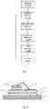
Fig. 1 schematically shows a structure of an on-line health management device for an insulated gate bipolar transistor according to an embodiment of the present disclosure; -
Fig. 2 schematically shows a structure of an insulated gate bipolar transistor according to an embodiment of the present disclosure; and -
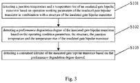
Fig. 3 is a flow chart of an on-line health management method for an insulated gate bipolar transistor according to an embodiment of the present disclosure. - The present disclosure will be explained in detail with reference to the accompanying drawings so as to make the purpose, the technical solution and advantages of the present disclosure clearer.
- The present disclosure provides an on-line health management device for an insulated gate bipolar transistor (IGBT). Specifically, as shown in
Fig. 1 , the on-line health management device comprises a sampling module, an extremum detection module, an electrothermal detection module, a degradation detection module, a lifetime detection module, and a warning module. - Specifically, as shown in
Fig. 2 , the IGBT comprises, from bottom to top, acopper base plate 1, asubstrate 2, aSi chip 3 and so on. Asolder layer 4 for fixing thesubstrate 2 and theSi chip 3 on thecopper base plate 1 is provided between thecopper base plate 1 and thesubstrate 2 as well as between thesubstrate 2 and theSi chip 3. The Sichip 3 is fixed on acopper coating layer 5 on one surface of thesubstrate 2 via thesolder layer 4, and the other surface of thesubstrate 2, which faces thecopper base plate 1, is also covered by acopper coating layer 5. The Sichip 3 is further provided thereon with an aluminum bonding wire 6, which electrically connects theSi chip 3 and acopper coating layer 5 which is on the same surface of thesubstrate 2 as theSi chip 3. - IGBTs with different structures and different material configurations have different failure mechanisms. Therefore, a detection device of the IGBT provided by the embodiment of the present disclosure should perform a comprehensive and all-round detection to the IGBT so as to obtain a precise detection result.
- In the present embodiment, the sampling module comprises a plurality of sensors for detecting and sampling operating condition parameters of the IGBT, and at least comprises sensors for respectively detecting working temperature, voltage and current of the IGBT. Besides, in order to obtain a more precise detection result, the sampling module can further comprise sensors for detecting parameters of the IGBT, such as working altitude, relative humidity, and vibration intensity.
- If the IGBT works under relatively extreme operating condition parameters, it indicates that the IGBT cannot work effectively, or even faces an imminent failure. The detection device in the present embodiment further comprises an extremum detection module. The extremum detection module is configured to detect whether the operating condition parameters each are within a corresponding extremum range, i.c., whether the IGBT is within a safe operating area. Safe operating areas mainly include a forward bias safe operating area, a reverse bias safe operating area and a short circuit safe operating area, and operating areas of a device should all meet restriction requirements of corresponding safe operating areas. Specifically, an IGBT as an ordinary power device and an IGBT as a traction power device have different extremum ranges which are shown in the following Table 1.
Table 1 Requirements Ordinary power device Traction power device Working altitude ≤ 1000 m ≤ 4000 m Working temperature 0°C ~ +40°C -40°C - +55° C Relative humidity 5% - 85% ≤ 95% Voltage fluctuation +/-10% +/- 24% Vibration intensity X\Y\Z axis < 10 m/s2 X axis 30 m/s2 Y axis 30 m/s2 Z axis 50 m/s2 - If the extremum detection module detects that one of the operating condition parameters, for example, temperature, goes beyond an extremum range thereof, it indicates that the
solder layer 4 within the IGBT is at a risk of fusion at this time, which causes the IGBT to be at a risk of failure. Then, the warning module pops up a corresponding warning reminder to a user, and the IGBT stops working temporarily. - On the contrary, if the extremum detection module detects that the operating condition parameters each are within a corresponding extremum range, the extremum detection module sends the operating condition parameters to the electrothermal detection module. Based on the operating condition parameters in combination with a structure of the IGBT, the electrothermal detection module detects a junction temperature and a temperature rise of the IGBT. The electrothermal detection module comprises a power loss model and a thermal modal, and detects the junction temperature and the temperature rise of the IGBT mainly by detecting power loss and thermal loss of the IGBT. The power loss model represents a property that the power loss changes with the voltage, the current and the temperature during operation of the IGBT, i.e., the temperature rise. The thermal model represents a thermal conduction property of a path through which the power loss of the IGBT flows in a form of heat, and is a key model for assessing the junction temperature of a power device.
- It should be explained that, the structure of the IGBT combined by the electrothermal detection module is set and stored in advance in a database of the on-line health management device by the user, which can be used directly by the electrothermal detection module when needed, instead of a specific structure detected in real time.
- Specifically, according to the power loss model, the power loss of the IGBT is calculated by a following formula: PTr_tot = Pcond_Tr + Psw_Tr_on + P sw_Tr_off , in which P cond_Tr is on-state loss of the IGBT, P sw_Tr_on is switch-on loss of the IGBT, and P sw_Tr_off is switch-off loss of the IGBT. Power loss of a diode is calculated by a following formula: PD_tot = Pcond_D + Psw_D_off, in which Pcond_D is on-state loss of the diode, and P sw_D_off is switch-on/off loss of the diode.
- The power loss generated during operation of the IGBT flows in the form of heat in a device, but a property of a heat dissipation path of the IGBT directly affects the junction temperature and lifetimes of materials of respective layers of the IGBT. During a heat conduction process, inconsistent coefficients of thermal expansion (CTE) of materials will cause a thermal stress, and thus performance degradation of the materials will occur. By means of the thermal model, thermal response circumstances of the device under different conditions of heat dissipation and conduction paths can be described, and therefore an assessing for a thermal design solution of a system can be provided. An equivalent circuit structure of the IGBT is set through a thermal transient experiment. Generally, a thermal resistance, a thermal capacity and so on are used to express a dynamic response action of a thermal conduction process, and a thermal response action of the IGBT can be expressed by a following formula:

- As shown in
Fig. 1 , the detection device provided in the present embodiment further comprises a degradation detection module which is configured to detect a performance degradation degree of the IGBT based on the operating condition parameters, the structure of the IGBT, the junction temperature and the temperature rise of the IGBT. In a normal operating condition, respective parts of the IGBT bear different stresses, and meanwhile respective components of the device are formed by different materials. - Accordingly, with respect to different stresses, action properties of various materials are different. For example, with respect to a mechanical stress, various materials show different strain and fatigue properties; and with respect to a temperature stress, different materials show different CTEs.
- Therefore, the degradation detection module in the present embodiment can be used to perform a statistic treatment to cycle times of temperatures and stresses so as to obtain corresponding failure cycles of different temperatures and stresses, and further a degradation degree of the IGBT can be better assessed. A process of the statistic treatment to the cycle times of the temperatures and the stresses normally comprises two steps. In
step 1, a procedure of pretreating stress information is performed. That is, curves of temperatures and stresses changing over time are converted, by a pretreating technology, into a group of fold lines having amplitudes changing over time. Instep 2, a statistic algorithm is used to calculate the cycle times of given temperature and stress spectra. Typically, a rainflow-counting algorithm is used. All fluctuation amplitudes in an entire fold line is divided into a plurality of equidifferent amplitude levels according to a certain rule, and then cycle times corresponding to respective amplitude levels are obtained by a statistical analysis. Finally, a statistic result of loads in a temperature-frequency form is obtained, which provides data support for a subsequent calculation of fatigue loss of the device and assessment of a lifetime thereof. - In addition, since an IGBT failure process is a result of combined action of multiple factors, degradation behaviors represented by the IGBT are different under different stresses. With continuous improvements of packaging technologies, a lifetime of the IGBT has been greatly prolonged. At present, fatigue of the
solder layer 4 and fall-off of the aluminum bonding wire 6 have become two main failure mechanisms. - The present disclosure provides a multi-parameter degradation model including a series of affection factors based on a great number of reliable experiments. The multi-parameter degradation model is expressed by a following formula:

- In the present embodiment, information fusion technology is used for a comprehensive processing and analysis to information of the device collected from different aspects. Based on this, a degradation degree and state of the device can be obtained in real time. That is, an analyzing and processing can be performed based on "big data".
- The information fusion technology is a multi-source information comprehensive processing technology. According to the information fusion technology, information in a same form or different forms measured at a same time point or different time points provided by a plurality of sensors having a same type or different types in a system are analyzed, processed and synthesized so as to obtain a comprehensive and consistent estimation of a measured object. A more precise and complete conclusion can be obtained based on a result of a multi-source information fusion than a single information source.
- Specifically, the multi-parameter degradation model is expressed by a following formula:

- Obviously, the performance degradation degree of the IGBT is not caused by one factor or two factors. The working process of the IGBT needs to be studied and understood carefully, and actions of respective potential factors need to be considered comprehensively. Influences of respective potential factors to performance of the IGBT should be analyzed separately, and multiple factors which have an influence on the performance of the IGBT can be obtained finally. Therefore, a comprehensive action of multiple factors should be combined during detection of the IGBT, so that the performance degradation degree of the IGBT can be detected more scientifically and precisely.
- Then, the lifetime detection module of the present embodiment can detect a consumed lifetime of the IGBT based on a precise performance degradation degree thereof. It can be known from Miller linear damage accumulation theory that, each temperature cycle and power cycle will cause certain damage to the lifetime of the IGBT. When the damage accumulates to a certain amount, a failure of the IGBT is caused finally.
- The consumed lifetime of the IGBT can be calculated and assessed by a following formula. When D≥1, it means that the IGBT fails.

- In the formula, ni represents consumption times corresponding to each junction temperature and temperature rise, and Nfi represents theoretical consumption times of the lifetime corresponding to each junction temperature and temperature rise.
- When it is detected that the consumed lifetime is larger than or equal to a preset lifetime, i.e., when D≥1, the warning module provides a failure warning. That is, the user is reminded to replace the IGBT by a special warning bell or by a warning window popped up on a user monitoring interface.
- To sum up, the present embodiment provides an on-line health management device for the IGBT. The on-line health management device detects a lifetime state of the IGBT based on operating condition parameters of the IGBT in combination with the structure of the IGBT so as to provide feed the lifetime state of the IGBT back to the user and remind the user to maintain or replace the IGBT in time, thereby ensuring a normal working of equipment with the IGBT.
- Further, the present embodiment further provides an on-line health management method for the IGBT. As shown in
Fig. 3 , the method comprises step S101, step S102 and step S103. In step S101, a junction temperature and a temperature rise of an insulated gate bipolar transistor is detected based on operating condition parameters of the insulated gate bipolar transistor in combination with a structure of the insulated gate bipolar transistor. In step S102, a performance degradation degree of the insulated gate bipolar transistor is detected based on the operating condition parameters, the structure, the junction temperature and the temperature rise of the insulated gate bipolar transistor. In step S103, a consumed lifetime of the insulated gate bipolar transistor is detected based on the performance degradation degree thereof. - The above embodiments are described only for better understanding, rather than restricting the present disclosure. Any person skilled in the art can make amendments and changes to the implementing forms or details without departing from the scope of the present disclosure. The protection scope of the present disclosure shall be determined by the scope as defined in the claims.
Claims (8)
- An on-line health management device for an insulated gate bipolar transistor, wherein the on-line health management device comprises:a sampling module, configured to sample the operating condition parameters of the insulated gate bipolar transistor;an extremum detection module, configured to detect whether the operating condition parameters each are within a corresponding extremum range or not, wherein if the operating condition parameters each are within a corresponding extremum range, the operating condition parameters are sent to the electrothermal detection module;an electrothermal detection module, configured to detect a junction temperature and a temperature rise of the insulated gate bipolar transistor based on operating condition parameters of the insulated gate bipolar transistor in combination with a structure of the insulated gate bipolar transistor;a degradation detection module, configured to detect a performance degradation degree of the insulated gate bipolar transistor based on the operating condition parameters, the structure, the junction temperature and the temperature rise of the insulated gate bipolar transistor; anda lifetime detection module, configured to detect a consumed lifetime of the insulated gate bipolar transistor based on the performance degradation degree thereof.
- The on-line health management device according to claim 1, further comprising:
a warning module, configured to detect whether the consumed lifetime is larger than or equal to a preset lifetime, wherein if the consumed lifetime is larger than or equal to the preset lifetime, a failure warning is provided. - The on-line health management device according to claim 2, characterized in that:if the extremum detection module detects that an operation condition parameter is beyond a corresponding extremum range, a detection result is sent to the warning module; andthe warning module is further configured to provide a failure warning based on the detection result of the extremum detection module.
- The on-line health management device according to any of claims 1 to 3, wherein the operating condition parameters at least include current, voltage, and working temperature.
- The on-line health management device according to claim 4, wherein the degradation detection module is configured to detect the performance degradation degree of the insulated gate bipolar transistor based on failure working cycles corresponding to the operating condition parameters, the structure, the junction temperature and the temperature rise of the insulated gate bipolar transistor in combination with proportion corresponding to the operating condition parameters, the structure, the junction temperature and the temperature rise of the insulated gate bipolar transistor.
- An on-line health management method for an insulated gate bipolar transistor, wherein the on-line health management method comprises steps of:sampling the operating condition parameters of the insulated gate bipolar transistor;detecting whether the operating condition parameters each are within a corresponding extremum range or not, wherein if the operating condition parameters each are within a corresponding extremum range, the operating condition parameters are sent to the electrothermal detection module;detecting (S101) a junction temperature and a temperature rise of the insulated gate bipolar transistor based on operating condition parameters of the insulated gate bipolar transistor in combination with a structure of the insulated gate bipolar transistor;detecting (S102) a performance degradation degree of the insulated gate bipolar transistor based on the operating condition parameters, the structure, the junction temperature and the temperature rise of the insulated gate bipolar transistor; anddetecting (S103) a consumed lifetime of the insulated gate bipolar transistor based on the performance degradation degree thereof.
- The on-line health management method according to claim 6, further comprising a step of:
detecting an operation state of the insulated gate bipolar transistor based on the performance degradation degree. - The on-line health management method according to claim 6, wherein if it is detected that an operation condition parameter is beyond a corresponding extremum range, the on-line health management method further comprises a step of:
providing a failure warning based on a detection result of the extremum detection module.
Applications Claiming Priority (2)
| Application Number | Priority Date | Filing Date | Title |
|---|---|---|---|
| CN201510745148.2A CN105486992B (en) | 2015-11-05 | 2015-11-05 | A kind of online health controller and method of insulated gate bipolar transistor |
| PCT/CN2016/104228 WO2017076275A1 (en) | 2015-11-05 | 2016-11-01 | Device and method for online health management of insulated gate bipolar transistor |
Publications (3)
| Publication Number | Publication Date |
|---|---|
| EP3373019A1 EP3373019A1 (en) | 2018-09-12 |
| EP3373019A4 EP3373019A4 (en) | 2019-07-03 |
| EP3373019B1 true EP3373019B1 (en) | 2022-10-19 |
Family
ID=55674104
Family Applications (1)
| Application Number | Title | Priority Date | Filing Date |
|---|---|---|---|
| EP16861543.3A Active EP3373019B1 (en) | 2015-11-05 | 2016-11-01 | Device and method for online health management of insulated gate bipolar transistor |
Country Status (5)
| Country | Link |
|---|---|
| US (1) | US20180284181A1 (en) |
| EP (1) | EP3373019B1 (en) |
| CN (1) | CN105486992B (en) |
| WO (1) | WO2017076275A1 (en) |
| ZA (1) | ZA201801800B (en) |
Cited By (1)
| Publication number | Priority date | Publication date | Assignee | Title |
|---|---|---|---|---|
| EP4513203A1 (en) * | 2023-08-25 | 2025-02-26 | Abb Schweiz Ag | Method and apparatus for estimating cyclic thermal stress |
Families Citing this family (22)
| Publication number | Priority date | Publication date | Assignee | Title |
|---|---|---|---|---|
| CN105486992B (en) * | 2015-11-05 | 2019-03-12 | 中车株洲电力机车研究所有限公司 | A kind of online health controller and method of insulated gate bipolar transistor |
| CN107544008B (en) * | 2016-06-24 | 2020-04-21 | 中车株洲电力机车研究所有限公司 | Vehicle-mounted IGBT state monitoring method and device |
| CN106301317B (en) * | 2016-08-30 | 2019-04-16 | 深圳市禾望电气股份有限公司 | A kind of method of adjustment and system of IGBT driving voltage |
| CN106443400B (en) * | 2016-09-14 | 2019-06-11 | 河北工业大学 | A method for establishing an electro-thermal-aging junction temperature calculation model for IGBT modules |
| CN108549001B (en) * | 2018-02-02 | 2021-10-12 | 上海大学 | System and method for detecting strain state of power electronic module |
| US20190250205A1 (en) * | 2018-02-13 | 2019-08-15 | GM Global Technology Operations LLC | Thermal model based health assessment of igbt |
| CN110850258B (en) * | 2018-07-26 | 2022-03-22 | 台达电子工业股份有限公司 | Power component failure judgment method and electronic device thereof |
| EP3627675A1 (en) * | 2018-09-21 | 2020-03-25 | Maschinenfabrik Reinhausen GmbH | Analyzing an operating condition of a power converter |
| CN109558681A (en) * | 2018-11-30 | 2019-04-02 | 北京新能源汽车股份有限公司 | Method and device for obtaining loss power of insulated gate bipolar transistor |
| CN109946576A (en) * | 2019-01-17 | 2019-06-28 | 西安工程大学 | A kind of life early warning method of IGBT module for driver |
| CN110426618B (en) * | 2019-07-16 | 2022-01-04 | 中国第一汽车股份有限公司 | Device life prediction method and device, vehicle and storage medium |
| CN110514979A (en) * | 2019-09-02 | 2019-11-29 | 重庆中涪科瑞工业技术研究院有限公司 | A kind of railcar traction drive IGBT module life-span prediction method |
| CN112448656B (en) * | 2019-09-03 | 2022-07-19 | 北京新能源汽车股份有限公司 | Motor controller working mode switching method and device and electric automobile |
| CN111190088B (en) * | 2019-12-30 | 2021-05-14 | 西安电子科技大学 | Method for extracting characteristic parameters of IGBT (insulated Gate Bipolar transistor) performance degradation |
| CN111521947B (en) * | 2020-04-27 | 2022-03-18 | 上海大学 | Aging failure diagnosis method for heat dissipation path of power module |
| CN112329244B (en) * | 2020-11-09 | 2022-06-14 | 西南交通大学 | Optimal power loss equivalent modeling method for IGBT junction temperature estimation |
| CN113125928A (en) * | 2021-04-20 | 2021-07-16 | 武汉大学 | IGBT module aging characterization method and system based on Miner theory |
| CN113406466B (en) * | 2021-06-03 | 2024-05-17 | 合肥工业大学 | IGBT module package aging on-line health management method and system |
| CN113567825B (en) * | 2021-07-26 | 2023-01-13 | 华北电力大学 | IGBT module bonding wire breakage online monitoring device, monitoring method and application |
| CN114337225B (en) * | 2021-12-30 | 2024-07-16 | 湖南大学 | Method for improving reliability of converter based on health status monitoring |
| CN116125243B (en) * | 2023-03-06 | 2023-07-04 | 迈思普电子股份有限公司 | MOS tube SOA test fixture and test method thereof |
| CN118275848B (en) * | 2024-05-27 | 2024-08-06 | 深圳平创半导体有限公司 | Service life assessment method and device for power semiconductor device and semiconductor device |
Family Cites Families (15)
| Publication number | Priority date | Publication date | Assignee | Title |
|---|---|---|---|---|
| JP2006254574A (en) * | 2005-03-09 | 2006-09-21 | Yaskawa Electric Corp | Inverter protection device |
| JP4591246B2 (en) * | 2005-07-14 | 2010-12-01 | 株式会社日立製作所 | Power converter |
| US8103463B2 (en) * | 2006-09-21 | 2012-01-24 | Impact Technologies, Llc | Systems and methods for predicting failure of electronic systems and assessing level of degradation and remaining useful life |
| CN102636291B (en) * | 2011-02-15 | 2013-12-25 | 三一电气有限责任公司 | IGBT (insulated gate bipolar transistor) conjunction temperature detection device and method thereof |
| JP6104512B2 (en) * | 2011-04-01 | 2017-03-29 | ローム株式会社 | Temperature detection device |
| CN102253320B (en) * | 2011-04-19 | 2013-06-05 | 南车株洲电力机车研究所有限公司 | Method for pre-warning failure of insulated gate bipolar transistor (IGBT) |
| DK2724170T3 (en) * | 2011-06-21 | 2015-12-14 | Wind Solutions As Kk | Method for estimation of life of the end of a power semiconductor devices |
| DE102011087764A1 (en) * | 2011-12-05 | 2013-06-06 | Converteam Gmbh | Method for determining service life consumption of e.g. insulated gate bipolar transistor in wind energy plant, involves determining characteristics of temperature cycles, and determining service life consumption based on cycles |
| EP2615467B1 (en) * | 2012-01-11 | 2014-06-18 | ABB Research Ltd. | System and method for monitoring in real time the operating state of an IGBT device |
| US9494657B2 (en) * | 2012-10-16 | 2016-11-15 | University Of Utah Research Foundation | State of health estimation of power converters |
| DE102013211038B3 (en) * | 2013-06-13 | 2014-10-16 | Siemens Aktiengesellschaft | Providing information about an aging state of a semiconductor device |
| CN103809098A (en) * | 2014-01-26 | 2014-05-21 | 中国科学院微电子研究所 | A system and method for detecting the reliability of IGBT power devices |
| CN104933308B (en) * | 2015-06-16 | 2018-07-20 | 工业和信息化部电子第五研究所 | Reliability estimation method towards domestic military IGBT module |
| CN104978459B (en) * | 2015-07-08 | 2017-11-21 | 电子科技大学 | A kind of IGBT method for predicting residual useful life |
| CN105486992B (en) * | 2015-11-05 | 2019-03-12 | 中车株洲电力机车研究所有限公司 | A kind of online health controller and method of insulated gate bipolar transistor |
-
2015
- 2015-11-05 CN CN201510745148.2A patent/CN105486992B/en active Active
-
2016
- 2016-11-01 US US15/764,999 patent/US20180284181A1/en not_active Abandoned
- 2016-11-01 WO PCT/CN2016/104228 patent/WO2017076275A1/en not_active Ceased
- 2016-11-01 EP EP16861543.3A patent/EP3373019B1/en active Active
-
2018
- 2018-03-16 ZA ZA2018/01800A patent/ZA201801800B/en unknown
Cited By (1)
| Publication number | Priority date | Publication date | Assignee | Title |
|---|---|---|---|---|
| EP4513203A1 (en) * | 2023-08-25 | 2025-02-26 | Abb Schweiz Ag | Method and apparatus for estimating cyclic thermal stress |
Also Published As
| Publication number | Publication date |
|---|---|
| WO2017076275A1 (en) | 2017-05-11 |
| US20180284181A1 (en) | 2018-10-04 |
| EP3373019A4 (en) | 2019-07-03 |
| EP3373019A1 (en) | 2018-09-12 |
| CN105486992B (en) | 2019-03-12 |
| ZA201801800B (en) | 2019-06-26 |
| CN105486992A (en) | 2016-04-13 |
Similar Documents
| Publication | Publication Date | Title |
|---|---|---|
| EP3373019A1 (en) | Device and method for online health management of insulated gate bipolar transistor | |
| Hosseinabadi et al. | A comprehensive overview of reliability assessment strategies and testing of power electronics converters | |
| Abuelnaga et al. | A review on IGBT module failure modes and lifetime testing | |
| Abuelnaga et al. | Power electronic converter reliability and prognosis review focusing on power switch module failures | |
| Hanif et al. | A comprehensive review toward the state-of-the-art in failure and lifetime predictions of power electronic devices | |
| Sun et al. | Condition monitoring IGBT module bond wires fatigue using short-circuit current identification | |
| Oh et al. | Physics-of-failure, condition monitoring, and prognostics of insulated gate bipolar transistor modules: A review | |
| Smet et al. | Ageing and failure modes of IGBT modules in high-temperature power cycling | |
| Hernes et al. | Failure analysis and lifetime assessment of IGBT power modules at low temperature stress cycles | |
| Degrenne et al. | A review of prognostics and health management for power semiconductor modules | |
| US5654896A (en) | Performance prediction method for semiconductor power modules and ICS | |
| JP2009043780A (en) | Semiconductor device | |
| CN112487651A (en) | Method for detecting service life of power device of photovoltaic converter | |
| Liu et al. | Overview of monitoring methods of press‐pack insulated gate bipolar transistor modules under different package failure modes | |
| Ma et al. | Online prediction method for the remaining useful life of power devices based on composite indicator | |
| Gatla et al. | Impact of mission profile on reliability of grid-connected photovoltaic inverter | |
| CN115600423A (en) | A method for evaluating the life of a motor controller | |
| EP1947433A1 (en) | Method for measuring temperature of semiconductor device and apparatus for measuring temperature of semiconductor device | |
| CN112327125B (en) | Method, equipment and storage medium for monitoring thermal resistance state of power semiconductor device crust | |
| Di Nuzzo et al. | Condition monitoring indicators for Si and SiC power modules | |
| Patil et al. | A fusion approach to IGBT power module prognostics | |
| Chen et al. | A comprehensive analytical and experimental investigation of wire bond life for IGBT modules | |
| Zhang et al. | Precursor parameter identification for power supply prognostics and health management | |
| Wileman et al. | Failure mechanisms of radar and RF systems | |
| Peng et al. | An online converter-level wear-out failure mode separation method for power semiconductor devices |
Legal Events
| Date | Code | Title | Description |
|---|---|---|---|
| STAA | Information on the status of an ep patent application or granted ep patent |
Free format text: STATUS: THE INTERNATIONAL PUBLICATION HAS BEEN MADE |
|
| PUAI | Public reference made under article 153(3) epc to a published international application that has entered the european phase |
Free format text: ORIGINAL CODE: 0009012 |
|
| STAA | Information on the status of an ep patent application or granted ep patent |
Free format text: STATUS: REQUEST FOR EXAMINATION WAS MADE |
|
| 17P | Request for examination filed |
Effective date: 20180516 |
|
| AK | Designated contracting states |
Kind code of ref document: A1 Designated state(s): AL AT BE BG CH CY CZ DE DK EE ES FI FR GB GR HR HU IE IS IT LI LT LU LV MC MK MT NL NO PL PT RO RS SE SI SK SM TR |
|
| AX | Request for extension of the european patent |
Extension state: BA ME |
|
| DAV | Request for validation of the european patent (deleted) | ||
| DAX | Request for extension of the european patent (deleted) | ||
| A4 | Supplementary search report drawn up and despatched |
Effective date: 20190531 |
|
| RIC1 | Information provided on ipc code assigned before grant |
Ipc: G01R 31/26 20140101AFI20190524BHEP Ipc: G01K 7/01 20060101ALI20190524BHEP |
|
| GRAP | Despatch of communication of intention to grant a patent |
Free format text: ORIGINAL CODE: EPIDOSNIGR1 |
|
| STAA | Information on the status of an ep patent application or granted ep patent |
Free format text: STATUS: GRANT OF PATENT IS INTENDED |
|
| INTG | Intention to grant announced |
Effective date: 20220601 |
|
| GRAS | Grant fee paid |
Free format text: ORIGINAL CODE: EPIDOSNIGR3 |
|
| GRAA | (expected) grant |
Free format text: ORIGINAL CODE: 0009210 |
|
| STAA | Information on the status of an ep patent application or granted ep patent |
Free format text: STATUS: THE PATENT HAS BEEN GRANTED |
|
| AK | Designated contracting states |
Kind code of ref document: B1 Designated state(s): AL AT BE BG CH CY CZ DE DK EE ES FI FR GB GR HR HU IE IS IT LI LT LU LV MC MK MT NL NO PL PT RO RS SE SI SK SM TR |
|
| REG | Reference to a national code |
Ref country code: GB Ref legal event code: FG4D |
|
| REG | Reference to a national code |
Ref country code: CH Ref legal event code: EP |
|
| REG | Reference to a national code |
Ref country code: DE Ref legal event code: R096 Ref document number: 602016075799 Country of ref document: DE |
|
| REG | Reference to a national code |
Ref country code: IE Ref legal event code: FG4D |
|
| REG | Reference to a national code |
Ref country code: AT Ref legal event code: REF Ref document number: 1525877 Country of ref document: AT Kind code of ref document: T Effective date: 20221115 |
|
| REG | Reference to a national code |
Ref country code: LT Ref legal event code: MG9D |
|
| REG | Reference to a national code |
Ref country code: NL Ref legal event code: MP Effective date: 20221019 |
|
| REG | Reference to a national code |
Ref country code: AT Ref legal event code: MK05 Ref document number: 1525877 Country of ref document: AT Kind code of ref document: T Effective date: 20221019 |
|
| PG25 | Lapsed in a contracting state [announced via postgrant information from national office to epo] |
Ref country code: NL Free format text: LAPSE BECAUSE OF FAILURE TO SUBMIT A TRANSLATION OF THE DESCRIPTION OR TO PAY THE FEE WITHIN THE PRESCRIBED TIME-LIMIT Effective date: 20221019 |
|
| PG25 | Lapsed in a contracting state [announced via postgrant information from national office to epo] |
Ref country code: SE Free format text: LAPSE BECAUSE OF FAILURE TO SUBMIT A TRANSLATION OF THE DESCRIPTION OR TO PAY THE FEE WITHIN THE PRESCRIBED TIME-LIMIT Effective date: 20221019 Ref country code: PT Free format text: LAPSE BECAUSE OF FAILURE TO SUBMIT A TRANSLATION OF THE DESCRIPTION OR TO PAY THE FEE WITHIN THE PRESCRIBED TIME-LIMIT Effective date: 20230220 Ref country code: NO Free format text: LAPSE BECAUSE OF FAILURE TO SUBMIT A TRANSLATION OF THE DESCRIPTION OR TO PAY THE FEE WITHIN THE PRESCRIBED TIME-LIMIT Effective date: 20230119 Ref country code: LT Free format text: LAPSE BECAUSE OF FAILURE TO SUBMIT A TRANSLATION OF THE DESCRIPTION OR TO PAY THE FEE WITHIN THE PRESCRIBED TIME-LIMIT Effective date: 20221019 Ref country code: FI Free format text: LAPSE BECAUSE OF FAILURE TO SUBMIT A TRANSLATION OF THE DESCRIPTION OR TO PAY THE FEE WITHIN THE PRESCRIBED TIME-LIMIT Effective date: 20221019 Ref country code: ES Free format text: LAPSE BECAUSE OF FAILURE TO SUBMIT A TRANSLATION OF THE DESCRIPTION OR TO PAY THE FEE WITHIN THE PRESCRIBED TIME-LIMIT Effective date: 20221019 Ref country code: AT Free format text: LAPSE BECAUSE OF FAILURE TO SUBMIT A TRANSLATION OF THE DESCRIPTION OR TO PAY THE FEE WITHIN THE PRESCRIBED TIME-LIMIT Effective date: 20221019 |
|
| PG25 | Lapsed in a contracting state [announced via postgrant information from national office to epo] |
Ref country code: RS Free format text: LAPSE BECAUSE OF FAILURE TO SUBMIT A TRANSLATION OF THE DESCRIPTION OR TO PAY THE FEE WITHIN THE PRESCRIBED TIME-LIMIT Effective date: 20221019 Ref country code: PL Free format text: LAPSE BECAUSE OF FAILURE TO SUBMIT A TRANSLATION OF THE DESCRIPTION OR TO PAY THE FEE WITHIN THE PRESCRIBED TIME-LIMIT Effective date: 20221019 Ref country code: LV Free format text: LAPSE BECAUSE OF FAILURE TO SUBMIT A TRANSLATION OF THE DESCRIPTION OR TO PAY THE FEE WITHIN THE PRESCRIBED TIME-LIMIT Effective date: 20221019 Ref country code: IS Free format text: LAPSE BECAUSE OF FAILURE TO SUBMIT A TRANSLATION OF THE DESCRIPTION OR TO PAY THE FEE WITHIN THE PRESCRIBED TIME-LIMIT Effective date: 20230219 Ref country code: HR Free format text: LAPSE BECAUSE OF FAILURE TO SUBMIT A TRANSLATION OF THE DESCRIPTION OR TO PAY THE FEE WITHIN THE PRESCRIBED TIME-LIMIT Effective date: 20221019 Ref country code: GR Free format text: LAPSE BECAUSE OF FAILURE TO SUBMIT A TRANSLATION OF THE DESCRIPTION OR TO PAY THE FEE WITHIN THE PRESCRIBED TIME-LIMIT Effective date: 20230120 |
|
| P01 | Opt-out of the competence of the unified patent court (upc) registered |
Effective date: 20230505 |
|
| REG | Reference to a national code |
Ref country code: CH Ref legal event code: PL |
|
| REG | Reference to a national code |
Ref country code: DE Ref legal event code: R097 Ref document number: 602016075799 Country of ref document: DE |
|
| REG | Reference to a national code |
Ref country code: BE Ref legal event code: MM Effective date: 20221130 |
|
| PG25 | Lapsed in a contracting state [announced via postgrant information from national office to epo] |
Ref country code: SM Free format text: LAPSE BECAUSE OF FAILURE TO SUBMIT A TRANSLATION OF THE DESCRIPTION OR TO PAY THE FEE WITHIN THE PRESCRIBED TIME-LIMIT Effective date: 20221019 Ref country code: RO Free format text: LAPSE BECAUSE OF FAILURE TO SUBMIT A TRANSLATION OF THE DESCRIPTION OR TO PAY THE FEE WITHIN THE PRESCRIBED TIME-LIMIT Effective date: 20221019 Ref country code: MC Free format text: LAPSE BECAUSE OF FAILURE TO SUBMIT A TRANSLATION OF THE DESCRIPTION OR TO PAY THE FEE WITHIN THE PRESCRIBED TIME-LIMIT Effective date: 20221019 Ref country code: LI Free format text: LAPSE BECAUSE OF NON-PAYMENT OF DUE FEES Effective date: 20221130 Ref country code: EE Free format text: LAPSE BECAUSE OF FAILURE TO SUBMIT A TRANSLATION OF THE DESCRIPTION OR TO PAY THE FEE WITHIN THE PRESCRIBED TIME-LIMIT Effective date: 20221019 Ref country code: DK Free format text: LAPSE BECAUSE OF FAILURE TO SUBMIT A TRANSLATION OF THE DESCRIPTION OR TO PAY THE FEE WITHIN THE PRESCRIBED TIME-LIMIT Effective date: 20221019 Ref country code: CZ Free format text: LAPSE BECAUSE OF FAILURE TO SUBMIT A TRANSLATION OF THE DESCRIPTION OR TO PAY THE FEE WITHIN THE PRESCRIBED TIME-LIMIT Effective date: 20221019 Ref country code: CH Free format text: LAPSE BECAUSE OF NON-PAYMENT OF DUE FEES Effective date: 20221130 |
|
| PLBE | No opposition filed within time limit |
Free format text: ORIGINAL CODE: 0009261 |
|
| STAA | Information on the status of an ep patent application or granted ep patent |
Free format text: STATUS: NO OPPOSITION FILED WITHIN TIME LIMIT |
|
| PG25 | Lapsed in a contracting state [announced via postgrant information from national office to epo] |
Ref country code: SK Free format text: LAPSE BECAUSE OF FAILURE TO SUBMIT A TRANSLATION OF THE DESCRIPTION OR TO PAY THE FEE WITHIN THE PRESCRIBED TIME-LIMIT Effective date: 20221019 Ref country code: LU Free format text: LAPSE BECAUSE OF NON-PAYMENT OF DUE FEES Effective date: 20221101 Ref country code: AL Free format text: LAPSE BECAUSE OF FAILURE TO SUBMIT A TRANSLATION OF THE DESCRIPTION OR TO PAY THE FEE WITHIN THE PRESCRIBED TIME-LIMIT Effective date: 20221019 |
|
| 26N | No opposition filed |
Effective date: 20230720 |
|
| GBPC | Gb: european patent ceased through non-payment of renewal fee |
Effective date: 20230119 |
|
| PG25 | Lapsed in a contracting state [announced via postgrant information from national office to epo] |
Ref country code: IE Free format text: LAPSE BECAUSE OF NON-PAYMENT OF DUE FEES Effective date: 20221101 Ref country code: GB Free format text: LAPSE BECAUSE OF NON-PAYMENT OF DUE FEES Effective date: 20230119 |
|
| PG25 | Lapsed in a contracting state [announced via postgrant information from national office to epo] |
Ref country code: SI Free format text: LAPSE BECAUSE OF FAILURE TO SUBMIT A TRANSLATION OF THE DESCRIPTION OR TO PAY THE FEE WITHIN THE PRESCRIBED TIME-LIMIT Effective date: 20221019 Ref country code: BE Free format text: LAPSE BECAUSE OF NON-PAYMENT OF DUE FEES Effective date: 20221130 |
|
| PG25 | Lapsed in a contracting state [announced via postgrant information from national office to epo] |
Ref country code: HU Free format text: LAPSE BECAUSE OF FAILURE TO SUBMIT A TRANSLATION OF THE DESCRIPTION OR TO PAY THE FEE WITHIN THE PRESCRIBED TIME-LIMIT; INVALID AB INITIO Effective date: 20161101 |
|
| PG25 | Lapsed in a contracting state [announced via postgrant information from national office to epo] |
Ref country code: CY Free format text: LAPSE BECAUSE OF FAILURE TO SUBMIT A TRANSLATION OF THE DESCRIPTION OR TO PAY THE FEE WITHIN THE PRESCRIBED TIME-LIMIT Effective date: 20221019 |
|
| PG25 | Lapsed in a contracting state [announced via postgrant information from national office to epo] |
Ref country code: MK Free format text: LAPSE BECAUSE OF FAILURE TO SUBMIT A TRANSLATION OF THE DESCRIPTION OR TO PAY THE FEE WITHIN THE PRESCRIBED TIME-LIMIT Effective date: 20221019 Ref country code: IT Free format text: LAPSE BECAUSE OF FAILURE TO SUBMIT A TRANSLATION OF THE DESCRIPTION OR TO PAY THE FEE WITHIN THE PRESCRIBED TIME-LIMIT Effective date: 20221019 |
|
| PG25 | Lapsed in a contracting state [announced via postgrant information from national office to epo] |
Ref country code: BG Free format text: LAPSE BECAUSE OF FAILURE TO SUBMIT A TRANSLATION OF THE DESCRIPTION OR TO PAY THE FEE WITHIN THE PRESCRIBED TIME-LIMIT Effective date: 20221019 |
|
| PG25 | Lapsed in a contracting state [announced via postgrant information from national office to epo] |
Ref country code: MT Free format text: LAPSE BECAUSE OF FAILURE TO SUBMIT A TRANSLATION OF THE DESCRIPTION OR TO PAY THE FEE WITHIN THE PRESCRIBED TIME-LIMIT Effective date: 20221019 |
|
| PG25 | Lapsed in a contracting state [announced via postgrant information from national office to epo] |
Ref country code: TR Free format text: LAPSE BECAUSE OF FAILURE TO SUBMIT A TRANSLATION OF THE DESCRIPTION OR TO PAY THE FEE WITHIN THE PRESCRIBED TIME-LIMIT Effective date: 20221019 |
|
| PGFP | Annual fee paid to national office [announced via postgrant information from national office to epo] |
Ref country code: DE Payment date: 20251124 Year of fee payment: 10 |
|
| PGFP | Annual fee paid to national office [announced via postgrant information from national office to epo] |
Ref country code: FR Payment date: 20251127 Year of fee payment: 10 |