EP3372992A1 - Display device and x-ray ct device - Google Patents
Display device and x-ray ct device Download PDFInfo
- Publication number
- EP3372992A1 EP3372992A1 EP15907813.8A EP15907813A EP3372992A1 EP 3372992 A1 EP3372992 A1 EP 3372992A1 EP 15907813 A EP15907813 A EP 15907813A EP 3372992 A1 EP3372992 A1 EP 3372992A1
- Authority
- EP
- European Patent Office
- Prior art keywords
- imaging condition
- imaging
- display device
- ray
- control element
- Prior art date
- Legal status (The legal status is an assumption and is not a legal conclusion. Google has not performed a legal analysis and makes no representation as to the accuracy of the status listed.)
- Withdrawn
Links
- 238000013170 computed tomography imaging Methods 0.000 claims abstract description 193
- 238000003384 imaging method Methods 0.000 claims description 94
- 239000000463 material Substances 0.000 claims description 39
- 238000012790 confirmation Methods 0.000 claims description 25
- 238000012545 processing Methods 0.000 claims description 12
- 230000004044 response Effects 0.000 claims description 4
- 230000001678 irradiating effect Effects 0.000 claims description 3
- 238000000034 method Methods 0.000 description 15
- 230000013011 mating Effects 0.000 description 12
- 230000008569 process Effects 0.000 description 12
- 230000008859 change Effects 0.000 description 9
- 230000006870 function Effects 0.000 description 9
- 238000012937 correction Methods 0.000 description 8
- 239000011347 resin Substances 0.000 description 8
- 229920005989 resin Polymers 0.000 description 8
- 238000001514 detection method Methods 0.000 description 6
- 238000010586 diagram Methods 0.000 description 5
- 230000006872 improvement Effects 0.000 description 4
- 229910001385 heavy metal Inorganic materials 0.000 description 2
- 229910052751 metal Inorganic materials 0.000 description 2
- 239000002184 metal Substances 0.000 description 2
- 238000012544 monitoring process Methods 0.000 description 2
- 230000001186 cumulative effect Effects 0.000 description 1
- 230000000694 effects Effects 0.000 description 1
- 239000011159 matrix material Substances 0.000 description 1
- 150000002739 metals Chemical class 0.000 description 1
- 230000004048 modification Effects 0.000 description 1
- 238000012986 modification Methods 0.000 description 1
- 238000003825 pressing Methods 0.000 description 1
Images


Classifications
-
- G—PHYSICS
- G01—MEASURING; TESTING
- G01N—INVESTIGATING OR ANALYSING MATERIALS BY DETERMINING THEIR CHEMICAL OR PHYSICAL PROPERTIES
- G01N23/00—Investigating or analysing materials by the use of wave or particle radiation, e.g. X-rays or neutrons, not covered by groups G01N3/00 – G01N17/00, G01N21/00 or G01N22/00
- G01N23/02—Investigating or analysing materials by the use of wave or particle radiation, e.g. X-rays or neutrons, not covered by groups G01N3/00 – G01N17/00, G01N21/00 or G01N22/00 by transmitting the radiation through the material
- G01N23/04—Investigating or analysing materials by the use of wave or particle radiation, e.g. X-rays or neutrons, not covered by groups G01N3/00 – G01N17/00, G01N21/00 or G01N22/00 by transmitting the radiation through the material and forming images of the material
-
- A—HUMAN NECESSITIES
- A61—MEDICAL OR VETERINARY SCIENCE; HYGIENE
- A61B—DIAGNOSIS; SURGERY; IDENTIFICATION
- A61B5/00—Measuring for diagnostic purposes; Identification of persons
- A61B5/74—Details of notification to user or communication with user or patient ; user input means
- A61B5/742—Details of notification to user or communication with user or patient ; user input means using visual displays
- A61B5/7435—Displaying user selection data, e.g. icons in a graphical user interface
-
- A—HUMAN NECESSITIES
- A61—MEDICAL OR VETERINARY SCIENCE; HYGIENE
- A61B—DIAGNOSIS; SURGERY; IDENTIFICATION
- A61B6/00—Apparatus or devices for radiation diagnosis; Apparatus or devices for radiation diagnosis combined with radiation therapy equipment
- A61B6/02—Arrangements for diagnosis sequentially in different planes; Stereoscopic radiation diagnosis
- A61B6/03—Computed tomography [CT]
- A61B6/032—Transmission computed tomography [CT]
-
- A—HUMAN NECESSITIES
- A61—MEDICAL OR VETERINARY SCIENCE; HYGIENE
- A61B—DIAGNOSIS; SURGERY; IDENTIFICATION
- A61B6/00—Apparatus or devices for radiation diagnosis; Apparatus or devices for radiation diagnosis combined with radiation therapy equipment
- A61B6/46—Arrangements for interfacing with the operator or the patient
- A61B6/461—Displaying means of special interest
-
- G—PHYSICS
- G01—MEASURING; TESTING
- G01N—INVESTIGATING OR ANALYSING MATERIALS BY DETERMINING THEIR CHEMICAL OR PHYSICAL PROPERTIES
- G01N23/00—Investigating or analysing materials by the use of wave or particle radiation, e.g. X-rays or neutrons, not covered by groups G01N3/00 – G01N17/00, G01N21/00 or G01N22/00
- G01N23/02—Investigating or analysing materials by the use of wave or particle radiation, e.g. X-rays or neutrons, not covered by groups G01N3/00 – G01N17/00, G01N21/00 or G01N22/00 by transmitting the radiation through the material
- G01N23/04—Investigating or analysing materials by the use of wave or particle radiation, e.g. X-rays or neutrons, not covered by groups G01N3/00 – G01N17/00, G01N21/00 or G01N22/00 by transmitting the radiation through the material and forming images of the material
- G01N23/046—Investigating or analysing materials by the use of wave or particle radiation, e.g. X-rays or neutrons, not covered by groups G01N3/00 – G01N17/00, G01N21/00 or G01N22/00 by transmitting the radiation through the material and forming images of the material using tomography, e.g. computed tomography [CT]
-
- G—PHYSICS
- G06—COMPUTING; CALCULATING OR COUNTING
- G06T—IMAGE DATA PROCESSING OR GENERATION, IN GENERAL
- G06T11/00—2D [Two Dimensional] image generation
- G06T11/003—Reconstruction from projections, e.g. tomography
-
- G—PHYSICS
- G06—COMPUTING; CALCULATING OR COUNTING
- G06T—IMAGE DATA PROCESSING OR GENERATION, IN GENERAL
- G06T11/00—2D [Two Dimensional] image generation
- G06T11/60—Editing figures and text; Combining figures or text
-
- A—HUMAN NECESSITIES
- A61—MEDICAL OR VETERINARY SCIENCE; HYGIENE
- A61B—DIAGNOSIS; SURGERY; IDENTIFICATION
- A61B6/00—Apparatus or devices for radiation diagnosis; Apparatus or devices for radiation diagnosis combined with radiation therapy equipment
- A61B6/40—Arrangements for generating radiation specially adapted for radiation diagnosis
- A61B6/4064—Arrangements for generating radiation specially adapted for radiation diagnosis specially adapted for producing a particular type of beam
- A61B6/4085—Cone-beams
-
- G—PHYSICS
- G01—MEASURING; TESTING
- G01N—INVESTIGATING OR ANALYSING MATERIALS BY DETERMINING THEIR CHEMICAL OR PHYSICAL PROPERTIES
- G01N23/00—Investigating or analysing materials by the use of wave or particle radiation, e.g. X-rays or neutrons, not covered by groups G01N3/00 – G01N17/00, G01N21/00 or G01N22/00
- G01N23/02—Investigating or analysing materials by the use of wave or particle radiation, e.g. X-rays or neutrons, not covered by groups G01N3/00 – G01N17/00, G01N21/00 or G01N22/00 by transmitting the radiation through the material
- G01N23/04—Investigating or analysing materials by the use of wave or particle radiation, e.g. X-rays or neutrons, not covered by groups G01N3/00 – G01N17/00, G01N21/00 or G01N22/00 by transmitting the radiation through the material and forming images of the material
- G01N23/044—Investigating or analysing materials by the use of wave or particle radiation, e.g. X-rays or neutrons, not covered by groups G01N3/00 – G01N17/00, G01N21/00 or G01N22/00 by transmitting the radiation through the material and forming images of the material using laminography or tomosynthesis
-
- G—PHYSICS
- G06—COMPUTING; CALCULATING OR COUNTING
- G06T—IMAGE DATA PROCESSING OR GENERATION, IN GENERAL
- G06T2200/00—Indexing scheme for image data processing or generation, in general
- G06T2200/24—Indexing scheme for image data processing or generation, in general involving graphical user interfaces [GUIs]
Definitions
- the present invention relates to a display device having a computer tomographic (CT) software function used in an X-ray CT device and an X-ray CT device having the same.
- CT computer tomographic
- a display device having a CT software function is employed in an industrial X-ray CT device.
- an X-ray radioscopic imaging device performs X-ray photography by obtaining a single piece of projection data, or by irradiating X-rays, sequentially obtaining a plurality of pieces of projection data, and displaying each of the projection data in real time (video display).
- video display a display device
- X-ray radioscopy it is possible to check whether or not the projection data presents an optimum image by monitoring the image in the middle of the X-ray radioscopy. Therefore, even when an imaging condition is not suitable, the imaging condition can be changed in the middle of the X-ray radioscopy on the basis of the monitoring result.
- the X-ray CT device obtains a reconstructed image (CT image) by performing a reconstruction process using a plurality of pieces of projection data (for example, approximately 600 to 2,400 pieces of data). Therefore, unlike the X-ray radioscopic imaging device, when CT imaging is performed by the X-ray CT device, it is not possible to check whether or not the reconstructed image is optimum until the CT imaging and the reconstruction process are terminated. Therefore, when the CT imaging condition is not suitable, it is necessary to restart the CT imaging and the reconstruction process from the beginning. Even when the CT imaging is restarted, a user is not allowed to know whether or not the reset (changed) CT imaging condition is optimum before checking the reconstructed image obtained from the restarted imaging. In some cases, it is necessary to repeat the CT imaging over and over until an optimum reconstructed image is obtained.
- CT image a reconstructed image
- the CT imaging is performed for various materials and structures with various image resolution requirements (such as a spatial resolution or a density resolution) and various imaging times. Therefore, since a wide variety of imaging conditions are set freely, the imaging conditions are to be set for each target object (work) as described below.
- the imaging condition includes a distance from a focal position to an X-ray detector (source-to-detector distance: SDD) in a vertical direction when the vertical line is drawn from the focal position of the X-ray tube to the X-ray detector, a distance from the focal position of the X-ray tube to a rotation center of the target object (source-to-rotation-center distance: SRD), a CT imaging mode (such as cone beam CT (CBCT)), a scan count, a total scan time, and the like.
- SDD source-to-detector distance: SDD
- SRD source-to-rotation-center distance
- CBCT cone beam CT
- the imaging condition setting has a lot of items and takes long time disadvantageously.
- a user who does not fully understand (who is not sufficiently experienced in) an industrial X-ray CT device performs the imaging condition setting, it is difficult to determine which setting is optimum.
- an object of the invention is to provide a display device and an X-ray CT device having a CT software function that enables an intuitive setting of an optimum CT imaging condition through a small number of steps with excellent operability.
- a display device having a computer tomographic (CT) software function used in an X-ray CT device, including control elements configured to register presets for a plurality of CT imaging conditions and arranged on a display screen using a two-dimensional index relating to image quality, wherein, as one of the control elements is selected, a CT imaging condition corresponding to the selected control element is set.
- CT computer tomographic
- a plurality of CT imaging conditions are created in advance as presets, and each preset is registered by mating with each control element.
- Each control element is arranged on the display screen using a two-dimensional index relating to image quality.
- the index relates to image quality and is two-dimensional. Therefore, even a user who does not fully understand the CT imaging condition can intuitively select and set an optimum CT imaging condition through a small number of steps just by visually checking and selecting the control element.
- new image quality improvement is required after CT imaging, and the imaging is restarted, what is selected for the required image quality becomes clear. Therefore, it is possible to easily change the CT imaging condition. As a result, it is possible to intuitively set an optimum CT imaging condition through a small number of steps with excellent operability.
- control element refers to a virtual tool of a graphical user interface (GUI) and is also called “Widget”.
- GUI graphical user interface
- a control element for the input setting including selection includes, for example, an icon, a dropdown list, a combobox, a radio button, a checkbox, a tap, or the like.
- the icon is displayed by symbolizing an object with a simple pictogram.
- the dropdown list allows a user to select one of the values from the list.
- the combobox allows a user to directly input a value and select the value from existing options.
- the radio button is also called an "option button" and is used to select one of the options defined in advance. As one of the radio buttons is selected (pressed), a button selected (pressed) previously returns to a non-selection (not pressed) state, so that only one of buttons is selected (pressed) at all times.
- the checkbox is used to select a plurality of items from several options.
- the tap is used to switchably display a document so that the managed document is switchably displayed by selecting the tap.
- the index of the display device includes, for example, a spatial resolution and a density resolution (that is, contrast).
- a CT imaging condition corresponding to the selected control element is selected.
- the index includes the spatial resolution and the density resolution relating to image quality and is two-dimensional. Therefore, even a user who does not fully understand the CT imaging condition can intuitively select and set an optimum CT imaging condition through a small number of steps just by visually checking and selecting the control element.
- the imaging is restarted as new image quality improvement is required after the CT imaging, what is selected for the spatial resolution or the density resolution to match the required image quality becomes clear. Therefore, it is possible to easily change the CT imaging condition.
- a preview image is preferably displayed as an image view serving as a reference of the output image corresponding to the selected condition.
- the preview image is displayed as an image view serving as a reference of the output image corresponding to the selected condition.
- control elements are displayed side by side in horizontal and vertical directions for each index on the display screen.
- the icon is displayed by symbolizing an object with a simple pictogram, a user can easily recognize the icon and more intuitively set an optimum CT imaging condition.
- control elements may be displayed independently for each index.
- the index includes the spatial resolution (simply, resolution) and the density resolution (contrast)
- a setting combination of the resolution and the contrast may be set for each imaging condition.
- the display device described above according to the invention preferably further includes imaging condition display means configured to display the set CT imaging condition.
- the CT imaging condition may be corrected immediately by checking the set CT imaging condition.
- the display device described above according to the invention further includes imaging condition input confirmation means configured to perform an input operation for confirming the set CT imaging condition, wherein CT imaging is performed on the basis of the confirmed CT imaging condition in response to the input operation to the imaging condition input confirmation means.
- imaging condition input confirmation means configured to perform an input operation for confirming the set CT imaging condition, wherein CT imaging is performed on the basis of the confirmed CT imaging condition in response to the input operation to the imaging condition input confirmation means.
- the display device described above according to the invention preferably further includes a control element that enables selection of a material on the display screen, wherein, when the control element is selected, a CT imaging condition is set for each material corresponding to the selected control element.
- a control element is further provided for each material and is arranged to match the two-dimensional index relating to image quality. All parameters necessary to set the CT imaging condition corresponding to the index and the material are set by selecting the control element. Therefore, even a user who does not fully understand the CT imaging condition can select an optimum CT imaging condition from the material of the target object (work) and the obtained image quality.
- the control element that enables selection of the material includes, for example, a dropdown list, a combobox, a radio button, a checkbox, or a tap.
- a preset of the registered CT imaging condition may be configured editably.
- a user can arbitrarily change or add the preset, can arbitrarily change the content of the material to be selected, or can arbitrarily add the type of the material.
- the display device described above according to the invention may be applied to an X-ray CT device.
- an X-ray CT device including: an X-ray source that generates an X-ray for irradiating X-rays onto a target object; a stage for placing the target object; an X-ray detector that detects the X-ray irradiated from the X-ray source to the target object and transmitted through the target object; the display device according to any one of claims 1 to 10, the display device having a CT software function including a function of setting a CT imaging condition; and a reconstruction processing unit that reconstructs a CT image of the target object from the data detected by the X-ray detector.
- the X-ray CT device has the display device according to the invention that enables an intuitive setting of an optimum CT imaging condition through a small number of steps with excellent operability. Therefore, it is possible to set an optimum CT imaging condition in advance before the CT imaging. Therefore, it is not necessary to restart the CT imaging. In addition, even when the CT imaging condition is not suitable, it is possible to reset (change) the CT imaging condition before the CT imaging by displaying, for example, the preview image. Therefore, it is not necessary to repeat the CT imaging over and over until an optimum reconstructed image is obtained.
- a plurality of CT imaging conditions are created as presets in advance, and each preset is registered by mating with each control element.
- Each control element is arranged on the display screen using a two-dimensional index relating to image quality. As a user selects any control element, a CT imaging condition corresponding to the selected control element is selected.
- the index relates to image quality and is two-dimensional. Therefore, it is possible to intuitively set an optimum CT imaging condition through a small number of steps with excellent operability just by visually checking and selecting the control element.
- the X-ray CT device has the display device according to the invention, that enables an intuitive setting of an optimum CT imaging condition through a small number of steps with excellent operability. Therefore, it is possible to set an optimum CT imaging condition in advance before the CT imaging.
- FIG. 1 is a schematic diagram illustrating an X-ray CT device along with a block diagram of the display device according to an embodiment of the invention.
- the X-ray CT device 1 includes an imaging unit 2 that images a target object O, a stage 3 for placing the target object O, a stage drive unit 4 that drives the stage 3, an imaging drive unit 5 that drives the imaging unit 2, a high-voltage generator 6 that generates a high voltage in order to supply a tube current or a tube voltage to an X-ray tube 21 of the imaging unit 2, and a reconstruction processing unit 7 that perform a reconstruction process for the projection data obtained by the X-ray detector 22 of the imaging unit 2.
- the imaging unit 2 includes an X-ray tube 21 that irradiates X-rays onto the target object O, and an X-ray detector 22 that detects X-rays irradiated from the X-ray tube 21 and transmitted through the target object O.
- Any type of device such as an image intensifier (I.I) or a flat panel type X-ray detector (FPD: Flat Panel Detector) may be employed as the X-ray detector 22 without any particular limitation. In this embodiment, it is assumed that a flat panel type X-ray detector (FPD) is employed as the X-ray detector 22.
- the X-ray tube 21 corresponds to an X-ray source according to the invention.
- the FPD has a plurality of detection elements arranged side by side across horizontal and vertical directions by mating with pixels, and the detection element detects an X-ray, so that data (electric charge signal) on the detected X-rays are output as an X-ray detection signal.
- an X-ray is irradiated from the X-ray tube 21 to the target object O, and the X-ray detector 22 such as the FPD detects the X-ray and outputs an X-ray detection signal.
- projection data are obtained by arranging pixel values based on the X-ray detection signal to match pixels (detection elements) .
- the stage drive unit 4 includes a motor, a drive shaft, or the like (not illustrated) to rotate the stage 3 on a horizontal plane around a Z-axis center in the drawing.
- the target object O By virtue of rotation of the stage 3 on the horizontal plane, the target object O also rotates around the Z-axis center on the horizontal plane, so that a plurality of pieces of projection data are obtained.
- the imaging drive unit 5 includes a motor, a drive shaft, or the like (not illustrated) .
- the X-ray CT imaging is performed by shifting the X-ray detector 22 or the X-ray tube 21 to face each other.
- a magnification ratio of the X-ray CT imaging may be changed by horizontally shifting the X-ray tube 21 or the X-ray detector 22 (X-direction in the drawings).
- the target object O may be scanned from an inclined direction by sloping the X-ray tube 21 or the X-ray detector 22 with respect to the X-axis.
- the high-voltage generator 6 generates a high voltage and applies the tube current or the tube voltage to the X-ray tube 21 to generate X-rays from the X-ray tube 21 and irradiate the X-rays to the target object O.
- the reconstruction processing unit 7 executes a reconstruction process well know in the art, such as a filtered back projection (FBP) method, a successive approximation method, or a combination thereof, using a plurality of projection data to obtain a reconstructed image for the target object O.
- FBP filtered back projection
- the display device 30 having a CT software function used in the X-ray CT device 1 has a memory unit 8, an input unit 9, a monitor 10, and a controller 11.
- the display device 30 has a graphical user interface (GUI).
- GUI graphical user interface
- the memory unit 8 includes a storage medium such as a read-only memory (ROM), a random-access memory (RAM), or a hard disk.
- the memory unit 8 has a preset table 8A regarding icons and presets registered for the icons.
- the icons stored in the preset table 8A and the presets for a plurality of CT imaging conditions are read onto the display screen of the monitor 10 (that is, the CT imaging condition setting screen 10A of Fig. 2 ) using the controller 11.
- the display device 30 is configured such that the icons for which presets for a plurality of CT imaging conditions are registered are arranged on the display screen of the monitor 10 (the CT imaging condition setting screen 10A of Fig. 2 ) along with a spatial resolution and a density resolution as a two-dimensional index relating to image quality.
- the display device 30 is configured such that a CT imaging condition corresponding to the selected icon is set by selecting icon.
- the CT imaging condition setting will be described below in more details.
- the input unit 9 transmits data or a command input from a user to the controller 11.
- the input unit 9 includes a keyboard and a pointing device such as a mouse, a joystick, a track ball, and a touch panel.
- the monitor 10 is configured to display a screen for setting the CT imaging condition (that is, the CT imaging condition setting screen 10A of Fig. 2 ) according to this embodiment.
- the projection data or the reconstructed image is displayed on the monitor 10 after the CT imaging.
- the CT imaging condition setting screen will also be described below in more details.
- the controller 11 comprehensively controls each part of the X-ray CT device 1 and the display device 30.
- the icons stored in the preset table 8A and the presets for a plurality of CT imaging conditions are read onto the display screen of the monitor 10 using the controller 11.
- an input operation for confirming the CT imaging condition is performed as a user clicks the imaging condition input confirmation button 10f (refer to Fig. 2 ).
- a control command based on the CT imaging condition is transmitted from the controller 11 to the stage drive unit 4, the imaging drive unit 5, or the high-voltage generator 6.
- data such as the projection data obtained by the X-ray detector 22 or the reconstructed image obtained by the reconstruction processing unit 7 are written or stored in the memory unit 8 using the controller 11, or are transmitted and output to the monitor 10 for display.
- the reconstruction processing unit 7 or the controller 11 includes a central processing unit (CPU) or the like.
- the reconstruction processing unit 7 may also include a graphic processing unit (GPU) or the like.
- Fig. 2 illustrates a type of the CT imaging condition setting screen on the display device according to an embodiment of the invention.
- Fig. 3 is a flowchart illustrating the CT imaging condition setting according to an embodiment of the invention.
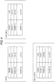
- Fig. 4 illustrates icons and a type of the table regarding presets registered for the icons.
- the monitor 10 is configured to display the CT imaging condition setting screen 10A (display screen) on which a plurality of icons 10a (nine icons in Fig. 2 ) are arranged.
- a plurality of CT imaging conditions are created in advance as presets, and the presets are registered by mating with the icons 10a one by one.
- Each icon 10a is arranged on the CT imaging condition setting screen 10A (display screen) using the two-dimensional index regarding image quality.
- the index includes a spatial resolution (that is, CT image size) 10b and a density resolution (contrast) 10c.
- the icons 10a are arranged side by side across horizontal and vertical directions on the CT imaging condition setting screen 10A (display screen) for each index (including the spatial resolution 10b and the density resolution 10c).
- the icons 10a are arranged in a 3x3 matrix shape along horizontal and vertical axes by setting the horizontal axis to the spatial resolution 10b and setting the vertical axis to the density resolution 10c.
- an icon representing the imaging time may be displayed along with each of the icons 10a by mating with the presets. As a user selects any icon 10a by clicking, for example, on a mouse, the selected icon 10a is preferably highlighted (for emphasis) in order to distinguish the selected icon 10a from other remaining icons 10a.
- a preview image 10d is displayed as an image view serving as a reference of the output image corresponding to the selected condition.
- the image view There is no particular limitation to the image view.
- a reconstructed image obtained in advance may be used as the image view, or a photograph or a schematic diagram may also be used as the image view.
- An imaging condition display unit 10e for presenting the set CT imaging condition is displayed on the CT imaging condition setting screen 10A (display screen) .
- the imaging condition display unit 10e is displayed in the right side of the CT imaging condition setting screen 10A (display screen).
- the display position of the imaging condition display unit 10e is not particularly limited.
- SCAN COUNT of Fig. 2 refers to frequency of performing the CT imaging by changing the height of the target object (work)
- MULTIPLE CUMULATIVE COUNT refers to frequency of performing CT imaging for the same position.
- BHC DATA refers to the beam hardening correction data.
- the imaging condition display unit 10e corresponds to "imaging condition display means" according to the invention.
- An imaging condition input confirmation button 10f (“START” in Fig. 2 ) is displayed on the CT imaging condition setting screen 10A (display screen).
- the imaging condition input confirmation button 10f corresponds to "imaging condition input confirmation means” according to the invention.
- the "START” button of Fig. 2 also has a function of starting execution of the CT imaging, so that the CT imaging starts as this button is pressed.
- a dropdown list 10g that allows a user to select a material of the imaging target is displayed on the CT imaging condition setting screen 10A (display screen).
- "RESIN” is selected as a material.
- light metals, heavy metals, electronic/electric components, and the like may be displayed as a list on the dropdown list 10g, so that a user can select one of them including the resin.
- an item lOh is displayed on the CT imaging condition setting screen 10A (display screen) .
- the item 10h is displayed in the upper side of th CT imaging condition setting screen 10A (display screen).
- the display position of the item 10h is not particularly limited.
- the content displayed on the item 10h is not particularly limited.
- the selected material (“RESIN” in Fig. 2 ) is displayed in the left side of the item 10h
- the set spatial resolution (CT image size) (“PIXEL SIZE” in Fig. 2 ) is displayed in the center of the item 10h
- the set total scan time is displayed in the right side of the item 10h.
- the imaging condition is roughly determined as illustrated in the flowchart of Fig. 3 .
- a material is selected (step S1).
- an icon suitable for a purpose is selected from the imaging condition icons arranged two-dimensionally (step S2).
- individual imaging conditions are displayed on the imaging condition display unit. Therefore, a user checks the individual imaging conditions (step S3). If the imaging condition is suitable, the imaging condition setting is terminated. If the condition is not suitable, the process returns to step S2, so that an imaging condition icon is selected again.
- the conditions displayed on the imaging condition display unit may also be directly changed.
- the imaging condition setting will be described by way of example.
- the material is set to "RESIN”.
- PRESET 01 is registered by mating with ICON 01.
- PRESET 02 is registered by mating with ICON 02, and so on.
- PRESET 09 is registered by mating with ICON 09
- a table is created by registering nine PRESETs 01 to 09 by mating with ICONs 01 to 09, respectively, for each resin.
- a table is created by registering nine PRESETs 11 to 19 by mating with ICONs 11 to 19, respectively, for each light metal
- a table is created by registering nine PRESETs 21 to 29 by mating with ICONs 21 to 29, respectively, for each heavy metal.
- This table creation process is performed as a factory setting performed in advance when the device is shipped in a factory. Therefore, an operator is not necessary to create the table individually.
- a material is selected from a target object (work) to be scanned.
- a target object is formed of resin
- a user selects "RESIN" from the list by clicking the dropdown list 10g (refer to Fig. 2 ).
- the table (refer to Fig. 4 ) stored in the preset table 8A (refer to Fig. 1 ) and obtained by registering nine PRESETS 01 to 09 mated with ICONs 01 to 09, respectively, for each resin is read onto the CT imaging condition setting screen 10A (refer to Fig. 2 ).
- a user selects the corresponding one from the icons 10a arranged on the CT imaging condition setting screen 10A (display screen) (refer to Fig. 2 ).
- the CT imaging condition corresponding to the selected icon is displayed on the imaging condition display unit 10e (refer to Fig. 2 ).
- a preview image 10d is displayed (refer to Fig. 2 ), and the spatial resolution of the CT imaging condition or the total scan time is displayed on the item 10h (refer to Fig. 2 ).
- a user checks the imaging condition on the basis of the CT imaging conditions (such as the imaging time or the resolution) displayed on the preview image 10d and the imaging condition display unit 10e.
- CT imaging conditions such as the imaging time or the resolution
- a user determines that the imaging condition is not suitable ("NG” in Fig. 3 )
- the process returns to step S2. If a user determines that the imaging condition is optimum ("OK” in Fig. 3 ), a user confirms the corresponding CT imaging condition by clicking the imaging condition input confirmation button 10f (refer to Fig. 2 ), and a series of imaging condition settings are terminated ("END" in Fig. 3 ).
- a control command based on the CT imaging condition determined in steps S1 to S3 of Fig. 3 is transmitted from the controller 11 (refer to Fig. 1 ) to the stage drive unit 4 (refer to Fig. 1 ), the imaging drive unit 5 (refer to Fig. 1 ), or the high-voltage generator 6 (refer to Fig. 6), so that the CT imaging is performed on the basis of the CT imaging condition.
- a plurality of CT imaging conditions are created in advance as presets, and each preset is created in advance as a control element (icons 10a in Fig. 2 ), so that each preset is registered by mating with each control element (icons 10a).
- Each control element (icons 10a) is arranged on the display screen (the CT imaging condition setting screen 10A in Fig. 2 ) with a two-dimensional index (the spatial resolution 10b and the density resolution 10c in Fig. 2 in this embodiment).
- the CT imaging condition corresponding to the selected control element (icon 10a) is selected.
- the index relates to image quality and is two-dimensional.
- control element herein refers to a virtual tool of a graphical user interface (GUI) as described above in “Summary of the Invention” and is also called “Widget”.
- GUI graphical user interface
- the icons 10a are employed as illustrated in Fig. 2 .
- the icon 10a is displayed by symbolizing an object with a simple pictogram.
- the index includes the spatial resolution (CT image size) 10b and the density resolution (contrast) 10c.
- CT image size the spatial resolution
- density resolution the density resolution
- the index is two-dimensional and includes the spatial resolution 10b and the density resolution 10c relating to image quality, even a user who does not fully understand the CT imaging condition can intuitively select and set an optimum CT imaging condition through a small number of steps just by visually checking and selecting the control element (icon 10a).
- a preview image 10d is preferably displayed as an image view serving as a reference of the output image corresponding to the selected condition.
- the preview image 10d is displayed as an image view serving as a reference of the output image corresponding to the selected condition.
- the icons 10a are arranged side by side in horizontal and vertical directions for each index (spatial resolution 10b and density resolution 10c) on the display screen (CT imaging condition setting screen 10A) as illustrated in Fig. 2 .
- the icon 10a is displayed by symbolizing an object with a simple pictogram, a user can easily recognize the icon 10a and more intuitively set an optimum CT imaging condition.
- imaging condition display means imaging condition display unit 10e in Fig. 2
- the CT imaging condition may be corrected immediately by checking the set CT imaging condition.
- imaging condition input confirmation means used to confirm the set CT imaging condition (the imaging condition input confirmation button 10f of Fig. 2 ) is provided so that CT imaging is performed on the basis of the confirmed CT imaging condition in response to an input operation of the imaging condition input confirmation means (imaging condition input confirmation button 10f).
- imaging condition input confirmation button 10f When a user determines that the set CT imaging condition is optimum, an input operation is performed on the imaging condition input confirmation means (imaging condition input confirmation button 10f), so that the input operation for confirming the CT imaging condition is performed.
- CT imaging is performed on the basis of the confirmed CT imaging condition.
- a control element (dropdown list 10g) is further provided for each material, and the control element (dropdown list 10g) is arranged to match the two-dimensional index (including the spatial resolution 10b and the density resolution 10c) relating to the image quality.
- the aforementioned control element that enables selection of the material is the dropdown list 10g as illustrated in Fig. 2 .
- the control element that enables selection of the material is the dropdown list 10g as illustrated in Fig. 2 .
- the dropdown list 10g allows a user to select one of the values from the list.
- the X-ray CT device 1 has the display device 30 according to this embodiment that enables an intuitive setting of an optimum CT imaging condition through a small number of steps with excellent operability. Therefore, it is possible to set an optimum CT imaging condition in advance before the CT imaging. Therefore, it is not necessary to restart the CT imaging. In addition, even when the CT imaging condition is not suitable, it is possible to reset (change) the CT imaging condition before CT imaging by displaying, for example, the preview image 10d as in this embodiment. Therefore, it is not necessary to repeat the CT imaging over and over until an optimum reconstructed image is obtained.
- the invention may be modified as follows without limiting to the aforementioned embodiment.
- the invention is suitable for an industrial X-ray CT device.
Landscapes
- Health & Medical Sciences (AREA)
- Engineering & Computer Science (AREA)
- Life Sciences & Earth Sciences (AREA)
- Physics & Mathematics (AREA)
- Pathology (AREA)
- General Health & Medical Sciences (AREA)
- General Physics & Mathematics (AREA)
- Medical Informatics (AREA)
- Theoretical Computer Science (AREA)
- Nuclear Medicine, Radiotherapy & Molecular Imaging (AREA)
- Radiology & Medical Imaging (AREA)
- Heart & Thoracic Surgery (AREA)
- Veterinary Medicine (AREA)
- Biomedical Technology (AREA)
- Biophysics (AREA)
- Public Health (AREA)
- Molecular Biology (AREA)
- Surgery (AREA)
- Animal Behavior & Ethology (AREA)
- Analytical Chemistry (AREA)
- Immunology (AREA)
- Chemical & Material Sciences (AREA)
- Biochemistry (AREA)
- Pulmonology (AREA)
- High Energy & Nuclear Physics (AREA)
- Optics & Photonics (AREA)
- Human Computer Interaction (AREA)
- Apparatus For Radiation Diagnosis (AREA)
- Analysing Materials By The Use Of Radiation (AREA)
Abstract
Description
- The present invention relates to a display device having a computer tomographic (CT) software function used in an X-ray CT device and an X-ray CT device having the same.
- Typically, a display device (graphical user interface) having a CT software function is employed in an industrial X-ray CT device. Note that an X-ray radioscopic imaging device performs X-ray photography by obtaining a single piece of projection data, or by irradiating X-rays, sequentially obtaining a plurality of pieces of projection data, and displaying each of the projection data in real time (video display). Thus, by performing X-ray radioscopy, it is possible to check whether or not the projection data presents an optimum image by monitoring the image in the middle of the X-ray radioscopy. Therefore, even when an imaging condition is not suitable, the imaging condition can be changed in the middle of the X-ray radioscopy on the basis of the monitoring result.
- In this regard, the X-ray CT device obtains a reconstructed image (CT image) by performing a reconstruction process using a plurality of pieces of projection data (for example, approximately 600 to 2,400 pieces of data). Therefore, unlike the X-ray radioscopic imaging device, when CT imaging is performed by the X-ray CT device, it is not possible to check whether or not the reconstructed image is optimum until the CT imaging and the reconstruction process are terminated. Therefore, when the CT imaging condition is not suitable, it is necessary to restart the CT imaging and the reconstruction process from the beginning. Even when the CT imaging is restarted, a user is not allowed to know whether or not the reset (changed) CT imaging condition is optimum before checking the reconstructed image obtained from the restarted imaging. In some cases, it is necessary to repeat the CT imaging over and over until an optimum reconstructed image is obtained.
- In this regard, it is necessary to set an optimum CT imaging condition in advance before CT imaging. In the field of the X-ray CT device of the related art, a technique of setting an optimum CT imaging condition has been proposed (for example, see
Patent Documents 1 and 2). Typically, when a user determines that the set CT imaging condition is optimum, the user performs an input operation for confirming the CT imaging condition by clicking an imaging condition input confirmation button displayed on a display screen of the graphical user interface (GUI). Then, the CT imaging is performed on the basis of the confirmed CT imaging condition. - In the field of the industrial X-ray CT device, the CT imaging is performed for various materials and structures with various image resolution requirements (such as a spatial resolution or a density resolution) and various imaging times. Therefore, since a wide variety of imaging conditions are set freely, the imaging conditions are to be set for each target object (work) as described below.
- X-ray Condition: the X-ray condition includes a tube current or a tube voltage of an X-ray tube that generates X-rays.
- Exposure Time: the exposure time is a net X-ray irradiation time.
- Number of Views
- Average Number: the number of views and the average number described above have the following relationship. Specifically, the "number of views" refers to an average number of scanned images for the same projection angle or for each projection angle including the vicinity of a target projection angle (that is, projection angles in the vicinity of the imaging time at the target projection angle), so that the number of scanned images required in the CT imaging becomes "number of views × average number" . For example, when the number of views is set to "600" and the average number is set to "3", the number of scanned images necessary in the CT imaging becomes "1,800 (= 600 × 3)". Note that, when the projection data are averaged at each projection angle including the vicinity of the target projection angle, the projection data at each projection angle are approximated to the projection data at the same angle as that of the target projection angle.
- Slice Thickness
- BH Correction Data Selection: the BH correction refers to "beam hardening correction". Note that the beam hardening correction herein refers to correction using image processing software (image processing algorithm).
- Scaling Factor: the scaling factor herein refers to a response characteristic used in grayscale correction (also called "gamma correction").
- In addition, the imaging condition includes a distance from a focal position to an X-ray detector (source-to-detector distance: SDD) in a vertical direction when the vertical line is drawn from the focal position of the X-ray tube to the X-ray detector, a distance from the focal position of the X-ray tube to a rotation center of the target object (source-to-rotation-center distance: SRD), a CT imaging mode (such as cone beam CT (CBCT)), a scan count, a total scan time, and the like.
-
- Patent Document 1:
JP-A-2009-112627 - Patent Document 2:
JP-A-2011-080971 - However, the imaging condition setting has a lot of items and takes long time disadvantageously. In addition, when a user who does not fully understand (who is not sufficiently experienced in) an industrial X-ray CT device performs the imaging condition setting, it is difficult to determine which setting is optimum.
- In view of the aforementioned problems, an object of the invention is to provide a display device and an X-ray CT device having a CT software function that enables an intuitive setting of an optimum CT imaging condition through a small number of steps with excellent operability.
- In order to achieve the aforementioned object, according to an aspect of the invention, there is provided a display device having a computer tomographic (CT) software function used in an X-ray CT device, including control elements configured to register presets for a plurality of CT imaging conditions and arranged on a display screen using a two-dimensional index relating to image quality, wherein, as one of the control elements is selected, a CT imaging condition corresponding to the selected control element is set.
- In the display device according to the invention, a plurality of CT imaging conditions are created in advance as presets, and each preset is registered by mating with each control element. Each control element is arranged on the display screen using a two-dimensional index relating to image quality. As a user selects any control element, a CT imaging condition corresponding to the selected control element is selected. The index relates to image quality and is two-dimensional. Therefore, even a user who does not fully understand the CT imaging condition can intuitively select and set an optimum CT imaging condition through a small number of steps just by visually checking and selecting the control element. In addition, in a case where new image quality improvement is required after CT imaging, and the imaging is restarted, what is selected for the required image quality becomes clear. Therefore, it is possible to easily change the CT imaging condition. As a result, it is possible to intuitively set an optimum CT imaging condition through a small number of steps with excellent operability.
- Herein, the control element refers to a virtual tool of a graphical user interface (GUI) and is also called "Widget". A control element for the input setting including selection includes, for example, an icon, a dropdown list, a combobox, a radio button, a checkbox, a tap, or the like.
- The icon is displayed by symbolizing an object with a simple pictogram. The dropdown list allows a user to select one of the values from the list. The combobox allows a user to directly input a value and select the value from existing options. The radio button is also called an "option button" and is used to select one of the options defined in advance. As one of the radio buttons is selected (pressed), a button selected (pressed) previously returns to a non-selection (not pressed) state, so that only one of buttons is selected (pressed) at all times. The checkbox is used to select a plurality of items from several options. The tap is used to switchably display a document so that the managed document is switchably displayed by selecting the tap.
- The index of the display device according to the invention described above includes, for example, a spatial resolution and a density resolution (that is, contrast). As a user selects any control element corresponding to any one of the spatial resolution and the density resolution, a CT imaging condition corresponding to the selected control element is selected. The index includes the spatial resolution and the density resolution relating to image quality and is two-dimensional. Therefore, even a user who does not fully understand the CT imaging condition can intuitively select and set an optimum CT imaging condition through a small number of steps just by visually checking and selecting the control element. In addition, in a case where the imaging is restarted as new image quality improvement is required after the CT imaging, what is selected for the spatial resolution or the density resolution to match the required image quality becomes clear. Therefore, it is possible to easily change the CT imaging condition. As a result, it is possible to intuitively set an optimum CT imaging condition through a small number of steps with excellent operability by selecting a control element corresponding to at least one of the spatial resolution or the density resolution.
- In the display device described above according to the invention, when the CT imaging condition is selected, a preview image is preferably displayed as an image view serving as a reference of the output image corresponding to the selected condition. By displaying the preview image as an image view serving as a reference of the output image corresponding to the selected condition, it is possible to display the preview image as an image view regarding what type of output image is obtained from the selected condition and display how the output image is changed for the selected CT imaging condition. In addition, it is possible to check what type of output image is obtained from the preview image without performing the CT imaging or the reconstruction process.
- In the display device described above according to the invention, it is preferable to arrange the control elements as icons side by side in horizontal and vertical directions for each index on the display screen. As described above, since the icon is displayed by symbolizing an object with a simple pictogram, a user can easily recognize the icon and more intuitively set an optimum CT imaging condition.
- In the display device described above according to the invention, the control elements may be displayed independently for each index. For example, in a case where the index includes the spatial resolution (simply, resolution) and the density resolution (contrast), a setting combination of the resolution and the contrast may be set for each imaging condition.
- The display device described above according to the invention preferably further includes imaging condition display means configured to display the set CT imaging condition. The CT imaging condition may be corrected immediately by checking the set CT imaging condition.
- The display device described above according to the invention further includes imaging condition input confirmation means configured to perform an input operation for confirming the set CT imaging condition, wherein CT imaging is performed on the basis of the confirmed CT imaging condition in response to the input operation to the imaging condition input confirmation means. When a user determines that the set CT imaging condition is optimum, an input operation is performed on the imaging condition input confirmation means, so that the input operation for confirming the CT imaging condition is performed. In addition, CT imaging is performed on the basis of the confirmed CT imaging condition.
- The display device described above according to the invention preferably further includes a control element that enables selection of a material on the display screen, wherein, when the control element is selected, a CT imaging condition is set for each material corresponding to the selected control element. A control element is further provided for each material and is arranged to match the two-dimensional index relating to image quality. All parameters necessary to set the CT imaging condition corresponding to the index and the material are set by selecting the control element. Therefore, even a user who does not fully understand the CT imaging condition can select an optimum CT imaging condition from the material of the target object (work) and the obtained image quality.
- In the display device described above according to the invention, the control element that enables selection of the material includes, for example, a dropdown list, a combobox, a radio button, a checkbox, or a tap. By configuring the control element that enables selection of the material using the dropdown list, the combobox, the radio button, the checkbox, or the tap, it is possible to allow a user to easily select the control element that enables selection of the material and select an optimum CT imaging condition on the basis of the material and the image quality.
- In the display device described above according to the invention, a preset of the registered CT imaging condition may be configured editably. In this configuration, for example, a user can arbitrarily change or add the preset, can arbitrarily change the content of the material to be selected, or can arbitrarily add the type of the material.
- The display device described above according to the invention may be applied to an X-ray CT device.
- Specifically, according to the invention, there is provided an X-ray CT device including: an X-ray source that generates an X-ray for irradiating X-rays onto a target object; a stage for placing the target object; an X-ray detector that detects the X-ray irradiated from the X-ray source to the target object and transmitted through the target object; the display device according to any one of
claims 1 to 10, the display device having a CT software function including a function of setting a CT imaging condition; and a reconstruction processing unit that reconstructs a CT image of the target object from the data detected by the X-ray detector. - The X-ray CT device according to the invention has the display device according to the invention that enables an intuitive setting of an optimum CT imaging condition through a small number of steps with excellent operability. Therefore, it is possible to set an optimum CT imaging condition in advance before the CT imaging. Therefore, it is not necessary to restart the CT imaging. In addition, even when the CT imaging condition is not suitable, it is possible to reset (change) the CT imaging condition before the CT imaging by displaying, for example, the preview image. Therefore, it is not necessary to repeat the CT imaging over and over until an optimum reconstructed image is obtained.
- In the display device according to the invention, a plurality of CT imaging conditions are created as presets in advance, and each preset is registered by mating with each control element. Each control element is arranged on the display screen using a two-dimensional index relating to image quality. As a user selects any control element, a CT imaging condition corresponding to the selected control element is selected. The index relates to image quality and is two-dimensional. Therefore, it is possible to intuitively set an optimum CT imaging condition through a small number of steps with excellent operability just by visually checking and selecting the control element.
- The X-ray CT device according to the invention has the display device according to the invention, that enables an intuitive setting of an optimum CT imaging condition through a small number of steps with excellent operability. Therefore, it is possible to set an optimum CT imaging condition in advance before the CT imaging.
-
-
Fig. 1 is a schematic diagram illustrating an X-ray CT device along with a block diagram illustrating a display device according to an embodiment of the invention. -
Fig. 2 illustrates a CT imaging condition setting screen of the display device according an embodiment of the invention. -
Fig. 3 is a flowchart illustrating a CT imaging condition setting process according to an embodiment of the invention. -
Fig. 4 illustrates a table containing icons and presets registered for the icons according to an embodiment of the invention. -
Fig. 5 illustrates a CT imaging condition setting screen of the display device according to a modification of the invention. - Embodiments of the invention will now be described with reference to the accompanying drawings.
Fig. 1 is a schematic diagram illustrating an X-ray CT device along with a block diagram of the display device according to an embodiment of the invention. - As illustrated in
Fig. 1 , theX-ray CT device 1 according to the embodiment includes animaging unit 2 that images a target object O, astage 3 for placing the target object O, astage drive unit 4 that drives thestage 3, animaging drive unit 5 that drives theimaging unit 2, a high-voltage generator 6 that generates a high voltage in order to supply a tube current or a tube voltage to anX-ray tube 21 of theimaging unit 2, and areconstruction processing unit 7 that perform a reconstruction process for the projection data obtained by theX-ray detector 22 of theimaging unit 2. - The
imaging unit 2 includes anX-ray tube 21 that irradiates X-rays onto the target object O, and anX-ray detector 22 that detects X-rays irradiated from theX-ray tube 21 and transmitted through the target object O. Any type of device such as an image intensifier (I.I) or a flat panel type X-ray detector (FPD: Flat Panel Detector) may be employed as theX-ray detector 22 without any particular limitation. In this embodiment, it is assumed that a flat panel type X-ray detector (FPD) is employed as theX-ray detector 22. TheX-ray tube 21 corresponds to an X-ray source according to the invention. - The FPD has a plurality of detection elements arranged side by side across horizontal and vertical directions by mating with pixels, and the detection element detects an X-ray, so that data (electric charge signal) on the detected X-rays are output as an X-ray detection signal. As a result, an X-ray is irradiated from the
X-ray tube 21 to the target object O, and theX-ray detector 22 such as the FPD detects the X-ray and outputs an X-ray detection signal. In addition, projection data are obtained by arranging pixel values based on the X-ray detection signal to match pixels (detection elements) . - The
stage drive unit 4 includes a motor, a drive shaft, or the like (not illustrated) to rotate thestage 3 on a horizontal plane around a Z-axis center in the drawing. By virtue of rotation of thestage 3 on the horizontal plane, the target object O also rotates around the Z-axis center on the horizontal plane, so that a plurality of pieces of projection data are obtained. - Similar to the
stage drive unit 4, theimaging drive unit 5 includes a motor, a drive shaft, or the like (not illustrated) . The X-ray CT imaging is performed by shifting theX-ray detector 22 or theX-ray tube 21 to face each other. In addition, a magnification ratio of the X-ray CT imaging may be changed by horizontally shifting theX-ray tube 21 or the X-ray detector 22 (X-direction in the drawings). In addition, the target object O may be scanned from an inclined direction by sloping theX-ray tube 21 or theX-ray detector 22 with respect to the X-axis. - The high-
voltage generator 6 generates a high voltage and applies the tube current or the tube voltage to theX-ray tube 21 to generate X-rays from theX-ray tube 21 and irradiate the X-rays to the target object O. Thereconstruction processing unit 7 executes a reconstruction process well know in the art, such as a filtered back projection (FBP) method, a successive approximation method, or a combination thereof, using a plurality of projection data to obtain a reconstructed image for the target object O. - The
display device 30 having a CT software function used in theX-ray CT device 1 has amemory unit 8, an input unit 9, amonitor 10, and acontroller 11. In addition, as a manipulation environment for an operator (user), thedisplay device 30 has a graphical user interface (GUI). - Using the
controller 11, data such as the projection data obtained by theX-ray detector 22 or the reconstructed image obtained by thereconstruction processing unit 7 are written and stored in thememory unit 8, are appropriately read as necessary, so that the projection data or the reconstructed image is transmitted and output to themonitor 10. Thememory unit 8 includes a storage medium such as a read-only memory (ROM), a random-access memory (RAM), or a hard disk. - In addition, according to this embodiment, the
memory unit 8 has a preset table 8A regarding icons and presets registered for the icons. When the CT imaging condition is set, the icons stored in the preset table 8A and the presets for a plurality of CT imaging conditions are read onto the display screen of the monitor 10 (that is, the CT imagingcondition setting screen 10A ofFig. 2 ) using thecontroller 11. - In this manner, the
display device 30 is configured such that the icons for which presets for a plurality of CT imaging conditions are registered are arranged on the display screen of the monitor 10 (the CT imagingcondition setting screen 10A ofFig. 2 ) along with a spatial resolution and a density resolution as a two-dimensional index relating to image quality. In addition, thedisplay device 30 is configured such that a CT imaging condition corresponding to the selected icon is set by selecting icon. The CT imaging condition setting will be described below in more details. - The input unit 9 transmits data or a command input from a user to the
controller 11. The input unit 9 includes a keyboard and a pointing device such as a mouse, a joystick, a track ball, and a touch panel. - The
monitor 10 is configured to display a screen for setting the CT imaging condition (that is, the CT imagingcondition setting screen 10A ofFig. 2 ) according to this embodiment. In addition, the projection data or the reconstructed image is displayed on themonitor 10 after the CT imaging. The CT imaging condition setting screen will also be described below in more details. - The
controller 11 comprehensively controls each part of theX-ray CT device 1 and thedisplay device 30. As described above, when the CT imaging condition is set, the icons stored in the preset table 8A and the presets for a plurality of CT imaging conditions are read onto the display screen of themonitor 10 using thecontroller 11. In addition, an input operation for confirming the CT imaging condition is performed as a user clicks the imaging conditioninput confirmation button 10f (refer toFig. 2 ). In order to perform the CT imaging based on the confirmed CT imaging condition, a control command based on the CT imaging condition is transmitted from thecontroller 11 to thestage drive unit 4, theimaging drive unit 5, or the high-voltage generator 6. Note that, after the CT imaging is performed, data such as the projection data obtained by theX-ray detector 22 or the reconstructed image obtained by thereconstruction processing unit 7 are written or stored in thememory unit 8 using thecontroller 11, or are transmitted and output to themonitor 10 for display. - According to this embodiment, the
reconstruction processing unit 7 or thecontroller 11 includes a central processing unit (CPU) or the like. Note that thereconstruction processing unit 7 may also include a graphic processing unit (GPU) or the like. - Next, the CT imaging condition setting will be described with reference to
Figs. 2 to 4 .Fig. 2 illustrates a type of the CT imaging condition setting screen on the display device according to an embodiment of the invention.Fig. 3 is a flowchart illustrating the CT imaging condition setting according to an embodiment of the invention.Fig. 4 illustrates icons and a type of the table regarding presets registered for the icons. - As illustrated in
Fig. 2 , themonitor 10 is configured to display the CT imagingcondition setting screen 10A (display screen) on which a plurality oficons 10a (nine icons inFig. 2 ) are arranged. A plurality of CT imaging conditions (nine conditions in this embodiment) are created in advance as presets, and the presets are registered by mating with theicons 10a one by one. Eachicon 10a is arranged on the CT imagingcondition setting screen 10A (display screen) using the two-dimensional index regarding image quality. - According to this embodiment, the index includes a spatial resolution (that is, CT image size) 10b and a density resolution (contrast) 10c. The
icons 10a are arranged side by side across horizontal and vertical directions on the CT imagingcondition setting screen 10A (display screen) for each index (including thespatial resolution 10b and thedensity resolution 10c). InFig. 2 , theicons 10a are arranged in a 3x3 matrix shape along horizontal and vertical axes by setting the horizontal axis to thespatial resolution 10b and setting the vertical axis to thedensity resolution 10c. - Note that an icon representing the imaging time may be displayed along with each of the
icons 10a by mating with the presets. As a user selects anyicon 10a by clicking, for example, on a mouse, the selectedicon 10a is preferably highlighted (for emphasis) in order to distinguish the selectedicon 10a from other remainingicons 10a. - When the CT imaging condition is selected, a
preview image 10d is displayed as an image view serving as a reference of the output image corresponding to the selected condition. There is no particular limitation to the image view. For example, a reconstructed image obtained in advance may be used as the image view, or a photograph or a schematic diagram may also be used as the image view. - An imaging
condition display unit 10e for presenting the set CT imaging condition is displayed on the CT imagingcondition setting screen 10A (display screen) . InFig. 2 , the imagingcondition display unit 10e is displayed in the right side of the CT imagingcondition setting screen 10A (display screen). However, the display position of the imagingcondition display unit 10e is not particularly limited. Note that "SCAN COUNT" ofFig. 2 refers to frequency of performing the CT imaging by changing the height of the target object (work), and "MULTIPLE CUMULATIVE COUNT" refers to frequency of performing CT imaging for the same position. "BHC DATA" refers to the beam hardening correction data. The imagingcondition display unit 10e corresponds to "imaging condition display means" according to the invention. - An imaging condition
input confirmation button 10f ("START" inFig. 2 ) is displayed on the CT imagingcondition setting screen 10A (display screen). The imaging conditioninput confirmation button 10f corresponds to "imaging condition input confirmation means" according to the invention. The "START" button ofFig. 2 also has a function of starting execution of the CT imaging, so that the CT imaging starts as this button is pressed. - A
dropdown list 10g that allows a user to select a material of the imaging target is displayed on the CT imagingcondition setting screen 10A (display screen). InFig. 2 , "RESIN" is selected as a material. Alternatively, for example, light metals, heavy metals, electronic/electric components, and the like may be displayed as a list on thedropdown list 10g, so that a user can select one of them including the resin. - In addition, an item lOh is displayed on the CT imaging
condition setting screen 10A (display screen) . InFig. 2 , theitem 10h is displayed in the upper side of th CT imagingcondition setting screen 10A (display screen). However, the display position of theitem 10h is not particularly limited. Furthermore, the content displayed on theitem 10h is not particularly limited. For example, as illustrated inFig. 2 , the selected material ("RESIN" inFig. 2 ) is displayed in the left side of theitem 10h, the set spatial resolution (CT image size) ("PIXEL SIZE" inFig. 2 ) is displayed in the center of theitem 10h, and the set total scan time is displayed in the right side of theitem 10h. - The imaging condition is roughly determined as illustrated in the flowchart of
Fig. 3 . First, a material is selected (step S1). Then, an icon suitable for a purpose is selected from the imaging condition icons arranged two-dimensionally (step S2). As a result, individual imaging conditions are displayed on the imaging condition display unit. Therefore, a user checks the individual imaging conditions (step S3). If the imaging condition is suitable, the imaging condition setting is terminated. If the condition is not suitable, the process returns to step S2, so that an imaging condition icon is selected again. When a part of the imaging conditions are changed, the conditions displayed on the imaging condition display unit may also be directly changed. - The imaging condition setting will be described by way of example. In this example, it is assumed that the material is set to "RESIN". As illustrated in
Fig. 4 , PRESET 01 is registered by mating withICON 01. Similarly, PRESET 02 is registered by mating withICON 02, and so on. Finally, as PRESET 09 is registered by mating withICON 09, a table is created by registering ninePRESETs 01 to 09 by mating withICONs 01 to 09, respectively, for each resin. Similarly, as another material, a table is created by registering ninePRESETs 11 to 19 by mating withICONs 11 to 19, respectively, for each light metal, and a table is created by registering ninePRESETs 21 to 29 by mating withICONs 21 to 29, respectively, for each heavy metal. This table creation process is performed as a factory setting performed in advance when the device is shipped in a factory. Therefore, an operator is not necessary to create the table individually. - A material is selected from a target object (work) to be scanned. For example, assuming that the target object is formed of resin, a user selects "RESIN" from the list by clicking the
dropdown list 10g (refer toFig. 2 ). The table (refer toFig. 4 ) stored in the preset table 8A (refer toFig. 1 ) and obtained by registering ninePRESETS 01 to 09 mated withICONs 01 to 09, respectively, for each resin is read onto the CT imagingcondition setting screen 10A (refer toFig. 2 ). - A user selects the corresponding one from the
icons 10a arranged on the CT imagingcondition setting screen 10A (display screen) (refer toFig. 2 ). The CT imaging condition corresponding to the selected icon is displayed on the imagingcondition display unit 10e (refer toFig. 2 ). In this case, apreview image 10d is displayed (refer toFig. 2 ), and the spatial resolution of the CT imaging condition or the total scan time is displayed on theitem 10h (refer toFig. 2 ). - A user checks the imaging condition on the basis of the CT imaging conditions (such as the imaging time or the resolution) displayed on the
preview image 10d and the imagingcondition display unit 10e. - If a user determines that the imaging condition is not suitable ("NG" in
Fig. 3 ), the process returns to step S2. If a user determines that the imaging condition is optimum ("OK" inFig. 3 ), a user confirms the corresponding CT imaging condition by clicking the imaging conditioninput confirmation button 10f (refer toFig. 2 ), and a series of imaging condition settings are terminated ("END" inFig. 3 ). - As the
START button 10f displayed inFig. 2 is pressed, a control command based on the CT imaging condition determined in steps S1 to S3 ofFig. 3 is transmitted from the controller 11 (refer toFig. 1 ) to the stage drive unit 4 (refer toFig. 1 ), the imaging drive unit 5 (refer toFig. 1 ), or the high-voltage generator 6 (refer to Fig. 6), so that the CT imaging is performed on the basis of the CT imaging condition. - In the
display device 30 according to this embodiment, a plurality of CT imaging conditions are created in advance as presets, and each preset is created in advance as a control element (icons 10a inFig. 2 ), so that each preset is registered by mating with each control element (icons 10a). Each control element (icons 10a) is arranged on the display screen (the CT imagingcondition setting screen 10A inFig. 2 ) with a two-dimensional index (thespatial resolution 10b and thedensity resolution 10c inFig. 2 in this embodiment). As a user selects any control element (icons 10a), the CT imaging condition corresponding to the selected control element (icon 10a) is selected. The index relates to image quality and is two-dimensional. Therefore, even a user who does not fully understand the CT imaging condition can intuitively select and set an optimum CT imaging condition through a small number of steps just by visually checking and selecting a control element (icon 10a). In addition, in a case where the imaging is restarted as new image quality improvement is required after the CT imaging, what is selected for the required image quality becomes clear. Therefore, it is possible to easily change the CT imaging condition. As a result, it is possible to intuitively set an optimum CT imaging condition through a small number of steps with excellent operability. - Here, the control element herein refers to a virtual tool of a graphical user interface (GUI) as described above in "Summary of the Invention" and is also called "Widget". As a control element for the input setting including selection, according to this embodiment, the
icons 10a are employed as illustrated inFig. 2 . As described above, theicon 10a is displayed by symbolizing an object with a simple pictogram. - According to this embodiment, as illustrated in
Fig. 2 , the index includes the spatial resolution (CT image size) 10b and the density resolution (contrast) 10c. As a user selects any control element (icon 10a) corresponding to at least one of the spatial resolution and the density resolution, the CT imaging condition corresponding to the selected control element (icon 10a) is selected. Since the index is two-dimensional and includes thespatial resolution 10b and thedensity resolution 10c relating to image quality, even a user who does not fully understand the CT imaging condition can intuitively select and set an optimum CT imaging condition through a small number of steps just by visually checking and selecting the control element (icon 10a). In addition, in a case where the imaging is restarted as new image quality improvement is required after the CT imaging, what is selected for thespatial resolution 10b or thedensity resolution 10c required for the image becomes clear. Therefore, it is possible to easily change the CT imaging condition. As a result, it is possible to intuitively set an optimum CT imaging condition through a small number of steps with excellent operability by selecting the control element (icon 10a) corresponding to at least one of thespatial resolution 10b and thedensity resolution 10c. - As illustrated in
Fig. 2 , when the CT imaging condition is selected, apreview image 10d is preferably displayed as an image view serving as a reference of the output image corresponding to the selected condition. By displaying thepreview image 10d as an image view serving as a reference of the output image corresponding to the selected condition, it is possible to display the preview image as an image view regarding what type of output image is obtained from the selected condition and display how the output image is changed for the selected CT imaging condition. In addition, it is possible to check what type of output image is obtained from thepreview image 10d without performing the CT imaging or the reconstruction process. - It is preferable to arrange the
icons 10a as the control elements side by side in horizontal and vertical directions for each index (spatial resolution 10b anddensity resolution 10c) on the display screen (CT imagingcondition setting screen 10A) as illustrated inFig. 2 . As described above, since theicon 10a is displayed by symbolizing an object with a simple pictogram, a user can easily recognize theicon 10a and more intuitively set an optimum CT imaging condition. - It is preferable to provide imaging condition display means (imaging
condition display unit 10e inFig. 2 ) for displaying the set CT imaging condition as illustrated inFig. 2 . The CT imaging condition may be corrected immediately by checking the set CT imaging condition. - As illustrated in
Fig. 2 , imaging condition input confirmation means used to confirm the set CT imaging condition (the imaging conditioninput confirmation button 10f ofFig. 2 ) is provided so that CT imaging is performed on the basis of the confirmed CT imaging condition in response to an input operation of the imaging condition input confirmation means (imaging conditioninput confirmation button 10f). When a user determines that the set CT imaging condition is optimum, an input operation is performed on the imaging condition input confirmation means (imaging conditioninput confirmation button 10f), so that the input operation for confirming the CT imaging condition is performed. In addition, CT imaging is performed on the basis of the confirmed CT imaging condition. - It is preferable to further provide a control element that enables selection of a material (the
dropdown list 10g ofFig. 2 in this embodiment), so that the CT imaging condition is set for each material corresponding to the selected control element (dropdown list 10g) when the control element (dropdown list 10g) is selected. A control element (dropdown list 10g) is further provided for each material, and the control element (dropdown list 10g) is arranged to match the two-dimensional index (including thespatial resolution 10b and thedensity resolution 10c) relating to the image quality. By selecting the control element (dropdown list 10g), both the index (includingspatial resolution 10b and thedensity resolution 10c) and the parameter necessary to set the CT imaging condition corresponding to the material are wholly set. Therefore, even a user who does not fully understand the CT imaging condition can select an optimum CT imaging condition from the material of the target object (work) and the obtained image quality. - According to this embodiment, the aforementioned control element that enables selection of the material is the
dropdown list 10g as illustrated inFig. 2 . By configuring the control element that enables selection of the material using thedropdown list 10g, it is possible to allow a user to easily select the control element that enables selection of the material and select an optimum CT imaging condition from the material and the image quality. Thedropdown list 10g allows a user to select one of the values from the list. - The
X-ray CT device 1 according this embodiment has thedisplay device 30 according to this embodiment that enables an intuitive setting of an optimum CT imaging condition through a small number of steps with excellent operability. Therefore, it is possible to set an optimum CT imaging condition in advance before the CT imaging. Therefore, it is not necessary to restart the CT imaging. In addition, even when the CT imaging condition is not suitable, it is possible to reset (change) the CT imaging condition before CT imaging by displaying, for example, thepreview image 10d as in this embodiment. Therefore, it is not necessary to repeat the CT imaging over and over until an optimum reconstructed image is obtained. - The invention may be modified as follows without limiting to the aforementioned embodiment.
- (1) In the aforementioned embodiment, the control element (
icon 10a in the aforementioned embodiment) is selected by clicking a mouse, and the material is selected from the list by clicking thedropdown list 10g (refer toFig. 2 ). Alternatively, by configuring the input unit 9 (refer toFig. 1 ) using a touch panel, the monitor 10 (refer toFig. 1 ) also functions as the input unit 9, so that a user may select the control element on the touch panel by pressing the control element with a finger. - (2) In the aforementioned embodiment, the imaging mode is set as illustrated in
Fig. 1 . Alternatively, any tomographic mode such as tomosynthesis may also be employed without a limitation. - (3) In the aforementioned embodiment, as the control element in which the presets for a plurality of CT imaging conditions are registered, the
icons 10a are employed as illustrated inFig. 2 . Alternatively, any control element such as thedropdown list 10g ofFig. 2 may also be employed as long as it is used to perform an input setting including selection. Alternatively, as a control element for performing the input setting including selection, for example, a combobox, a radio button, a checkbox, a tap, or the like may also be employed. The combobox allows a user to directly input a value and select the value from existing options. The radio button is also called an "option button" and is used to select one of the options defined in advance. As one of the radio buttons is selected (pressed), a button selected (pressed) previously returns to a non-selection (not pressed) state, so that only one of buttons is selected (pressed) at all times. The checkbox is used to select a plurality of items from several options. The tap is used to switchably display documents so that the managed documents are displayed switchably by selecting the tap. - (4) In the aforementioned embodiment, the control element enables selection of a material is the
dropdown list 10g as illustrated inFig. 2 . Alternatively, the combobox, the radio button, the checkbox, or the tap described above may also be employed as described above. - (5) In the aforementioned embodiment, the index includes the spatial resolution (CT image size) 10b and the density resolution (contrast) 10c as illustrated in
Fig. 2 . Alternatively, any two-dimensional index other than the spatial resolution or the density resolution may also be employed as long as it relates to image quality. For example, two parameters such as a dynamic range for expressing a brightness or color pattern range or a signal-to-noise (S/N) ratio regarding noise may be selected, and the selected parameters may be used as the two-dimensional index relating to image quality. Alternatively, any one of the spatial resolution or the density resolution may be selected, and another one of the dynamic range or the S/N ratio may be selected, so that the selected parameters may be used as the two-dimensional index relating to image quality. - (6) In the aforementioned embodiment, when the CT imaging condition is selected, the
preview image 10d is displayed as an image view serving as a reference of the output image corresponding to the selected condition as illustrated inFig. 2 . However, it is not absolutely necessary to display the preview image. Anyway, it is preferable to display the preview image as in the aforementioned embodiment in order to check what type of output image is obtained without performing the CT imaging or the reconstruction process. - (7) In the aforementioned embodiment, the control elements as the
icons 10a are arranged side by side in horizontal and vertical directions for each index (thespatial resolution 10b and thedensity resolution 10c) on the display screen (CT imagingcondition setting screen 10A) as illustrated inFig. 2 . Alternatively, the control elements may be displayed independently for each index. For example, in a case where the index includes the spatial resolution (simply, resolution) and the density resolution (contrast) as in the aforementioned embodiment, a setting combination of the resolution and the contrast may be set for each imaging condition as illustrated inFig. 5 . - (8) In the aforementioned embodiment, the display device includes the imaging condition display means (imaging
condition display unit 10e ofFig. 2 ) for displaying the set CT imaging condition. However, it is not absolutely necessary to provide the imaging condition display means (imagingcondition display unit 10e). Alternatively, it is preferable to provide the imaging condition display means (imagingcondition display unit 10e) as in the aforementioned embodiment in order to check the set CT imaging condition. - (9) In the aforementioned embodiment, the imaging condition input confirmation means used to perform an input operation for confirming the set CT imaging condition (the imaging condition
input confirmation button 10f ofFig. 2 ) also serves as the imaging start button. Alternatively, separate buttons may be employed for each purpose. In order to prevent the CT imaging from being automatically performed even when the set CT imaging condition is not suitable, another imaging condition input confirmation means (imaging conditioninput confirmation button 10f) may be provided separately from the imaging start button. That is, it is checked whether or not the CT imaging condition is suitable. When a user determines that the imaging condition is optimum, an input operation to the imaging condition input confirmation means (imaging conditioninput confirmation button 10f) may be performed to confirm the CT imaging condition. Then, the CT imaging may be performed on the basis of the confirmed CT imaging condition when the imaging start button is pressed again. - (10) In the aforementioned embodiment, the control element (the
dropdown list 10g ofFig. 2 in the aforementioned embodiment) enables selection of a material is further provided on the display screen. The CT imaging condition for each material corresponding to the selected control element (dropdown list 10g) is set when this control element (dropdown list 10g) is selected. However, it is not absolutely necessary to set the CT imaging condition for each material as long as the target object (work) is a single type. - (11) The display device may be configured such that a user can arbitrarily change or add the preset. In addition, the display device may be configured such that the content of the material can be arbitrarily changed, or the type of the material can be arbitrarily added. In this manner, the display device may be configured such that the registered CT imaging condition preset is editable.
- As described above, the invention is suitable for an industrial X-ray CT device.
-
- 1 X-ray CT device
- 3 Stage
- 7 Reconstruction processing unit
- 8A Preset table
- 10 Monitor
- 10A CT imaging condition setting screen (display screen)
- 10a Icon
- 10b Spatial resolution (CT image size)
- 10c Density resolution (contrast)
- 10d Preview image
- 10e Imaging condition display unit
- 10f Imaging condition input confirmation button
- 10g Dropdown list
- 21 X-ray tube
- 22 X-ray detector
- 30 Display device
- O Target object
Claims (11)
- A display device having a computer tomographic (CT) software function used in an X-ray CT device, comprising control elements configured to register presets for a plurality of CT imaging conditions and arranged on a display screen using a two-dimensional index relating to image quality,
wherein, as one of the control elements is selected, a CT imaging condition corresponding to the selected control element is set. - The display device according to claim 1, wherein the index includes a spatial resolution and a density resolution.
- The display device according to claim 1, wherein, when the CT imaging condition is selected, a preview image is displayed as an image view serving as a reference of an output image corresponding to the selected condition.
- The display device according to claim 1, wherein the control elements are icons arranged side by side across horizontal and vertical directions for each index on the display screen.
- The display device according to claim 1, wherein the control elements are displayed independently for each index.
- The display device according to claim 1, further comprising imaging condition display means configured to display the set CT imaging condition.
- The display device according to claim 1, further comprising imaging condition input confirmation means configured to perform an input operation for confirming the set CT imaging condition,
wherein CT imaging is performed on the basis of the confirmed CT imaging condition in response to the input operation to the imaging condition input confirmation means. - The display device according to any one of claims 1 to 7, further comprising a control element that enables selection of a material on the display screen,
wherein, when the control element is selected, a CT imaging condition is set for each material corresponding to the selected control element. - The display device according to claim 8, wherein the control element that enables selection of the material includes a dropdown list, a combobox, a radio button, a checkbox, or a tap.
- The display device according to any one of claims 1 to 7, wherein a preset of the registered CT imaging condition is configured editably.
- An X-ray CT device comprising:an X-ray source that generates an X-ray for irradiating X-rays onto a target object;a stage for placing the target object;an X-ray detector that detects the X-ray irradiated from the X-ray source to the target object and transmitted through the target object;a display device having a CT software function including a function of setting a CT imaging condition; anda reconstruction processing unit that reconstructs a CT image of the target object from the data detected by the X-ray detector,wherein the display device is the display device according to any one of claims 1 to 10.
Applications Claiming Priority (1)
| Application Number | Priority Date | Filing Date | Title |
|---|---|---|---|
| PCT/JP2015/081230 WO2017077627A1 (en) | 2015-11-05 | 2015-11-05 | Display device and x-ray ct device |
Publications (2)
| Publication Number | Publication Date |
|---|---|
| EP3372992A1 true EP3372992A1 (en) | 2018-09-12 |
| EP3372992A4 EP3372992A4 (en) | 2018-12-26 |
Family
ID=58663183
Family Applications (1)
| Application Number | Title | Priority Date | Filing Date |
|---|---|---|---|
| EP15907813.8A Withdrawn EP3372992A4 (en) | 2015-11-05 | 2015-11-05 | Display device and x-ray ct device |
Country Status (5)
| Country | Link |
|---|---|
| US (1) | US10724971B2 (en) |
| EP (1) | EP3372992A4 (en) |
| JP (1) | JP6519663B2 (en) |
| CN (1) | CN108449983B (en) |
| WO (1) | WO2017077627A1 (en) |
Families Citing this family (10)
| Publication number | Priority date | Publication date | Assignee | Title |
|---|---|---|---|---|
| US10902619B2 (en) * | 2016-10-26 | 2021-01-26 | Duke University | Systems and methods for determining quality metrics of an image or images based on an edge gradient profile and characterizing regions of interest in an image or images |
| JP6746634B2 (en) * | 2018-06-25 | 2020-08-26 | シャープ株式会社 | Book digitizing device and book digitizing method |
| JP7257761B2 (en) * | 2018-09-13 | 2023-04-14 | 東芝Itコントロールシステム株式会社 | Radiographic inspection equipment |
| JP7143567B2 (en) * | 2018-09-14 | 2022-09-29 | 株式会社島津テクノリサーチ | Material testing machine and radiation CT equipment |
| CN109171704A (en) * | 2018-09-19 | 2019-01-11 | 深圳市理邦精密仪器股份有限公司 | Method, apparatus, terminal and the computer readable storage medium of ecg wave form analysis |
| JP7164474B2 (en) * | 2019-03-26 | 2022-11-01 | 東芝Itコントロールシステム株式会社 | Radiographic image quality adjustment device |
| JP7355525B2 (en) * | 2019-05-23 | 2023-10-03 | 東芝Itコントロールシステム株式会社 | Radiation inspection equipment |
| JP7501166B2 (en) * | 2020-07-03 | 2024-06-18 | オムロン株式会社 | X-ray inspection equipment |
| JP7501167B2 (en) | 2020-07-03 | 2024-06-18 | オムロン株式会社 | X-ray inspection equipment |
| JP7160871B2 (en) * | 2020-07-21 | 2022-10-25 | 日本電子株式会社 | Charged particle beam device and setting support method |
Family Cites Families (16)
| Publication number | Priority date | Publication date | Assignee | Title |
|---|---|---|---|---|
| US5986662A (en) * | 1996-10-16 | 1999-11-16 | Vital Images, Inc. | Advanced diagnostic viewer employing automated protocol selection for volume-rendered imaging |
| JPH11126697A (en) * | 1997-10-23 | 1999-05-11 | Shimadzu Corp | X-ray control device |
| JP2004279058A (en) * | 2003-03-12 | 2004-10-07 | Shimadzu Corp | X-ray ct device |
| DE602004004821T2 (en) * | 2003-11-28 | 2007-10-18 | Koninklijke Philips Electronics N.V. | SYSTEM FOR DISPLAYING IMAGES WITH MULTIPLE ATTRIBUTES |
| DE102005004383B4 (en) | 2005-01-31 | 2007-04-12 | Siemens Ag | Method and device for controlling an imaging modality |
| JP5171215B2 (en) | 2007-11-08 | 2013-03-27 | ジーイー・メディカル・システムズ・グローバル・テクノロジー・カンパニー・エルエルシー | X-ray CT system |
| JP2009226203A (en) * | 2008-02-28 | 2009-10-08 | Fujifilm Corp | Radiation image capturing system, radiation image capturing method, and program |
| US9113799B2 (en) * | 2009-07-30 | 2015-08-25 | Telesystems Co., Ltd. | Radiation imaging apparatus and imaging method using radiation |
| JP2011080971A (en) | 2009-10-08 | 2011-04-21 | Toshiba It & Control Systems Corp | Ct equipment |
| DE102009056721A1 (en) * | 2009-12-02 | 2011-06-09 | Siemens Aktiengesellschaft | Method for supporting the selection of a recording configuration, computed tomography device and data carrier |
| US9254107B2 (en) * | 2010-09-07 | 2016-02-09 | Hitachi Medical Corporation | X-ray CT apparatus and tube current determination method |
| US20120257713A1 (en) * | 2011-04-06 | 2012-10-11 | Julien Baptiste Pierre Noel | Non-Destructive Analysis of an Object |
| US9949704B2 (en) * | 2012-05-14 | 2018-04-24 | Bayer Healthcare Llc | Systems and methods for determination of pharmaceutical fluid injection protocols based on x-ray tube voltage |
| US9078565B2 (en) * | 2012-10-04 | 2015-07-14 | General Electric Company | Dual display CT scanner user interface |
| JP6234077B2 (en) | 2013-06-18 | 2017-11-22 | キヤノン株式会社 | Tomosynthesis imaging control device, imaging device, imaging system, control method, and program for causing computer to execute the control method |
| JP6438408B2 (en) * | 2013-10-24 | 2018-12-12 | キヤノン株式会社 | Information processing apparatus, information processing method, control apparatus, control system, control method, tomosynthesis imaging apparatus, X-ray imaging apparatus, image processing apparatus, image processing system, image processing method, and computer program |
-
2015
- 2015-11-05 US US15/772,968 patent/US10724971B2/en active Active
- 2015-11-05 WO PCT/JP2015/081230 patent/WO2017077627A1/en active Application Filing
- 2015-11-05 EP EP15907813.8A patent/EP3372992A4/en not_active Withdrawn
- 2015-11-05 JP JP2017548583A patent/JP6519663B2/en active Active
- 2015-11-05 CN CN201580084328.9A patent/CN108449983B/en active Active
Also Published As
| Publication number | Publication date |
|---|---|
| CN108449983A (en) | 2018-08-24 |
| EP3372992A4 (en) | 2018-12-26 |
| JPWO2017077627A1 (en) | 2018-08-16 |
| US10724971B2 (en) | 2020-07-28 |
| JP6519663B2 (en) | 2019-05-29 |
| CN108449983B (en) | 2023-09-05 |
| US20180328864A1 (en) | 2018-11-15 |
| WO2017077627A1 (en) | 2017-05-11 |
Similar Documents
| Publication | Publication Date | Title |
|---|---|---|
| US10724971B2 (en) | Display device and x-ray CT device | |
| CN108738341B (en) | Spiral CT device | |
| US20130184537A1 (en) | Medical image diagnosis apparatus and computer-readable medium | |
| US20070053478A1 (en) | X-ray ct apparatus and x-ray radiographic method | |
| US20140037057A1 (en) | X-ray imaging apparatus, and method of setting imaging area of x-ray imaging apparatus | |
| JP5573688B2 (en) | Radiography equipment | |
| US9398888B2 (en) | Radiation imaging system and method for controlling the same | |
| CN111134699A (en) | Radiation imaging system and method, control device, and computer-readable medium | |
| JP6412921B2 (en) | X-ray CT apparatus and medical image display method | |
| US11069060B2 (en) | Image processing apparatus and radiographic image data display method | |
| JP2013215273A (en) | Radiation imaging system, control apparatus, and control method | |
| JP7257761B2 (en) | Radiographic inspection equipment | |
| JP2020027101A (en) | X-ray imaging device | |
| JP5968153B2 (en) | Control device, control method, and program | |
| JP2015116365A (en) | Medical image diagnostic apparatus | |
| JP2015116365A5 (en) | ||
| US9679106B2 (en) | Medical information display apparatus | |
| CN111951317A (en) | Reconstruction device | |
| JP7118584B2 (en) | Medical image diagnostic device, medical imaging device and medical image display device | |
| JP2023168124A (en) | X-ray ct apparatus and reconstruction method of tomographic image | |
| JP7164474B2 (en) | Radiographic image quality adjustment device | |
| US20220188980A1 (en) | Image processing apparatus, display method, and display program | |
| JP2022162852A (en) | Medical image display device, medical image display method, and program | |
| CN105982684A (en) | X-ray equipment and control method and console thereof | |
| JP7098319B2 (en) | X-ray diagnostic device |
Legal Events
| Date | Code | Title | Description |
|---|---|---|---|
| STAA | Information on the status of an ep patent application or granted ep patent |
Free format text: STATUS: THE INTERNATIONAL PUBLICATION HAS BEEN MADE |
|
| PUAI | Public reference made under article 153(3) epc to a published international application that has entered the european phase |
Free format text: ORIGINAL CODE: 0009012 |
|
| STAA | Information on the status of an ep patent application or granted ep patent |
Free format text: STATUS: REQUEST FOR EXAMINATION WAS MADE |
|
| 17P | Request for examination filed |
Effective date: 20180529 |
|
| AK | Designated contracting states |
Kind code of ref document: A1 Designated state(s): AL AT BE BG CH CY CZ DE DK EE ES FI FR GB GR HR HU IE IS IT LI LT LU LV MC MK MT NL NO PL PT RO RS SE SI SK SM TR |
|
| AX | Request for extension of the european patent |
Extension state: BA ME |
|
| A4 | Supplementary search report drawn up and despatched |
Effective date: 20181126 |
|
| RIC1 | Information provided on ipc code assigned before grant |
Ipc: G06T 11/60 20060101ALI20181120BHEP Ipc: G01N 23/04 20180101AFI20181120BHEP Ipc: A61B 5/00 20060101ALI20181120BHEP |
|
| DAV | Request for validation of the european patent (deleted) | ||
| DAX | Request for extension of the european patent (deleted) | ||
| STAA | Information on the status of an ep patent application or granted ep patent |
Free format text: STATUS: EXAMINATION IS IN PROGRESS |
|
| 17Q | First examination report despatched |
Effective date: 20210406 |
|
| STAA | Information on the status of an ep patent application or granted ep patent |
Free format text: STATUS: EXAMINATION IS IN PROGRESS |
|
| STAA | Information on the status of an ep patent application or granted ep patent |
Free format text: STATUS: THE APPLICATION IS DEEMED TO BE WITHDRAWN |
|
| 18D | Application deemed to be withdrawn |
Effective date: 20230601 |