EP3372976B1 - Verfahren und system zur identifizierung von konnektivität in einem glasfaserübertragungsnetz (ofc) - Google Patents
Verfahren und system zur identifizierung von konnektivität in einem glasfaserübertragungsnetz (ofc) Download PDFInfo
- Publication number
- EP3372976B1 EP3372976B1 EP17163926.3A EP17163926A EP3372976B1 EP 3372976 B1 EP3372976 B1 EP 3372976B1 EP 17163926 A EP17163926 A EP 17163926A EP 3372976 B1 EP3372976 B1 EP 3372976B1
- Authority
- EP
- European Patent Office
- Prior art keywords
- transducer device
- unique identifier
- ultrasound
- node
- patch cord
- Prior art date
- Legal status (The legal status is an assumption and is not a legal conclusion. Google has not performed a legal analysis and makes no representation as to the accuracy of the status listed.)
- Active
Links
Images


Classifications
-
- H—ELECTRICITY
- H04—ELECTRIC COMMUNICATION TECHNIQUE
- H04B—TRANSMISSION
- H04B10/00—Transmission systems employing electromagnetic waves other than radio-waves, e.g. infrared, visible or ultraviolet light, or employing corpuscular radiation, e.g. quantum communication
- H04B10/27—Arrangements for networking
-
- G—PHYSICS
- G01—MEASURING; TESTING
- G01M—TESTING STATIC OR DYNAMIC BALANCE OF MACHINES OR STRUCTURES; TESTING OF STRUCTURES OR APPARATUS, NOT OTHERWISE PROVIDED FOR
- G01M11/00—Testing of optical apparatus; Testing structures by optical methods not otherwise provided for
-
- G—PHYSICS
- G02—OPTICS
- G02B—OPTICAL ELEMENTS, SYSTEMS OR APPARATUS
- G02B6/00—Light guides; Structural details of arrangements comprising light guides and other optical elements, e.g. couplings
-
- H—ELECTRICITY
- H04—ELECTRIC COMMUNICATION TECHNIQUE
- H04B—TRANSMISSION
- H04B10/00—Transmission systems employing electromagnetic waves other than radio-waves, e.g. infrared, visible or ultraviolet light, or employing corpuscular radiation, e.g. quantum communication
- H04B10/07—Arrangements for monitoring or testing transmission systems; Arrangements for fault measurement of transmission systems
- H04B10/075—Arrangements for monitoring or testing transmission systems; Arrangements for fault measurement of transmission systems using an in-service signal
- H04B10/077—Arrangements for monitoring or testing transmission systems; Arrangements for fault measurement of transmission systems using an in-service signal using a supervisory or additional signal
-
- H—ELECTRICITY
- H04—ELECTRIC COMMUNICATION TECHNIQUE
- H04B—TRANSMISSION
- H04B10/00—Transmission systems employing electromagnetic waves other than radio-waves, e.g. infrared, visible or ultraviolet light, or employing corpuscular radiation, e.g. quantum communication
- H04B10/25—Arrangements specific to fibre transmission
-
- H—ELECTRICITY
- H04—ELECTRIC COMMUNICATION TECHNIQUE
- H04B—TRANSMISSION
- H04B11/00—Transmission systems employing ultrasonic, sonic or infrasonic waves
-
- H—ELECTRICITY
- H04—ELECTRIC COMMUNICATION TECHNIQUE
- H04Q—SELECTING
- H04Q1/00—Details of selecting apparatus or arrangements
- H04Q1/02—Constructional details
- H04Q1/13—Patch panels for monitoring, interconnecting or testing circuits, e.g. patch bay, patch field or jack field; Patching modules
- H04Q1/135—Patch panels for monitoring, interconnecting or testing circuits, e.g. patch bay, patch field or jack field; Patching modules characterized by patch cord details
- H04Q1/136—Patch panels for monitoring, interconnecting or testing circuits, e.g. patch bay, patch field or jack field; Patching modules characterized by patch cord details having patch field management or physical layer management arrangements
Definitions
- the present disclosure relates to the field of telecommunications. Particularly, but not exclusively, the present disclosure relates to a device for identifying connectivity in an Optical Fiber Communication (OFC) network.
- OFC Optical Fiber Communication
- a central office network comprises a plurality of nodes.
- a link between two or more nodes exist to enable communication between the nodes.
- OFC Optical Fiber Communication
- the link between the two or more nodes are enabled by a Fiber Optic (FO) patch cord.
- FO Fiber Optic
- a technician has to replace the faulty FO patch cord by connecting a new FO patch cord to the nodes. Due to large number of FO patch cords, often the technician may not connect the new FO patch cord to the correct nodes.
- the FO patch cords are placed in a tray placed at a first node. The tray may be placed below racks of the first node.
- the FO patch cords are wired to the second node.
- the wiring is made by passing the FO patch cords underneath tiles of the central office.
- the FO patch cords emerges and are placed on another tray, which may be placed below racks of the second node.
- the technician cannot identify connectivity of the FO patch cord between the first node and the second node.
- the first node and the second node may be at different rooms and different floors of the central office. Hence, tracking the FO patch cords is a tedious task.
- Traditional systems provide solutions to identify correct nodes for connecting the new FO patch cord.
- One such system comprises providing physical connections (wire) from one node to another node.
- Such systems result in additional hardware, making the telecommunication system more complex.
- cost associated with providing physical connections to every node is very high.
- Other traditional systems involve installation of a transmitter at one node and a receiver at another node. Whenever, there is a fault in a node, the transmitter transmits a signal with various parameters related to the node, and a receiver at the other end receives the transmitted message. Thus, a technician can identify the correct node and can replace the FO patch cord.
- RF Radio Frequency
- the RF shield blocks the RF signals, and the traditional systems may not be able to transmit information to identify the correct node. Also, the installation of the transmitter and receiver involves high cost. Thus, the traditional systems do not provide an efficient and cost effective solution for identifying connectivity between nodes in the central office network.
- US Patent Application US 2012/281509 A1 describes automatically tracking patching connections in communications systems by transmitting an acoustic signal including a unique identifier embedded therein over a patch cord, and receiving the acoustic signal at the second connector port whereby the unique identifier is extracted and a patching connection between the transmitting and the receiving entity is logged in the database.
- a system for identifying connectivity in an Optical Fiber Communication (OFC) network a method for identifying connectivity in an OFC network, as set forth in claims 1 and 7, respectively.
- OFC Optical Fiber Communication
- the present disclosure relates to a connectivity identification system for identifying connectivity in an Optical Fiber Communication, OFC, network (100) comprising a first node (102) and a second node (103).
- the connectivity identification system comprises an ultrasound communicator (107) and a transducer device (101) communicatively connected to the ultrasound communicator (107).
- the ultrasound communicator (107) is configured to generate a unique identifier corresponding to each Fiber Optic, FO, patch cord connected to a transmitting port (105) of the first node (102), transmit an ultrasound signal modulated with the unique identifier through the transducer device (101), through an outer jacket of a FO patch cord among a plurality of FO patch cords connected between a the transmitting port (105) of the first node (102) and a receiving port (106) of the second node (103), wherein a frequency of the ultrasound signal is selected from a set of predefined frequencies, and wherein the ultrasound signal is transmitted at the selected frequency based on one or more parameters of the transmitting port (105), one or more parameters of the receiving port (106) and one or more parameters of the FO patch cord, and wherein the generated unique identifier corresponds to the selected frequency; and transmit the unique identifier to the receiving port of the second node (103) via a wireless signal.
- the ultrasound communicator (107) is configured to receive the ultrasound signal from the transducer device (101), wherein the transducer device (101) receives the ultrasound signal from an outer jacket of one of the plurality of FO patch cords, receive the wireless signal from the transducer device (101), wherein the received wireless signal comprises the unique identifier, demodulate the ultrasound signal to retrieve the unique identifier, and compare the unique identifier received via the wireless signal with the unique identifier retrieved by demodulation of the ultrasound signal and identify the receiving port (106) based on the comparison.
- the present disclosure relates to a method of identifying connectivity in an Optical Fiber Communication, OFC, network (100) comprising a first node (102) and a second node (103).
- the method comprises generating, by a connectivity identification system, a unique identifier corresponding to each Fiber Optic, FO, patch cord connected to a transmitting port (105) of the first node (102).
- the method further comprises transmitting, by the connectivity identification system, an ultrasound signal modulated with a unique identifier, through an outer jacket of a FO patch cord among a plurality of FO patch cords connected between a transmitting port (105) of the first node (102) and a receiving port of the second node (103) wherein a frequency of the ultrasound signal is selected from a set of predefined frequencies, and wherein the ultrasound signal is transmitted at the selected frequency based on one or more parameters of the transmitting port (105), one or more parameters of the receiving port (106) and one or more parameters of the FO patch cord, and wherein the generated unique identifier corresponds to the selected frequency.
- the method further comprises receiving, by the connectivity identification system, the ultrasound signal from an outer jacket of one of the FO patch cords connected to the second node (103), receiving, by the connectivity identification system, the wireless signal from the transducer device (101), wherein the received wireless signal comprises the unique identifier, demodulating, by the connectivity identification system, the ultrasound signal to retrieve the unique identifier, comparing, by the connectivity identification system, the unique identifier received via the wireless signal with the unique identifier retrieved by demodulation of the ultrasound signal and identifying, by the connectivity identification system, the receiving port (106) based on the comparison.
- any block diagrams herein represent conceptual views of illustrative systems embodying the principles of the present subject matter.
- any flow charts, flow diagrams, state transition diagrams, random code, and the like represent various processes which may be substantially represented in computer readable medium and executed by a computer or processor, whether or not such computer or processor is explicitly shown.
- Embodiments of the present disclosure relate to a connectivity identification system and a method for identifying connectivity between nodes in an Optical Fiber Communication (OFC) network in a central office.
- the connectivity identification system comprises an ultrasound transducer for transmitting and receiving ultrasound signals.
- the connectivity identification system further comprises an ultrasound communicator to configure the transducer device as a transmitter when the transducer device is connected to a first node of the OFC network and configure the transducer device as a receiver when the transducer device is connected to a second node of the OFC network.
- the transducer device transmits ultrasound signals through a Fiber Optic (FO) patch cord, and the transducer device or a similar transducer device receives the ultrasound signal when configured as a receiver. Further, the received ultrasound signal is used to identify connectivity between the first node and the second node.
- FO Fiber Optic
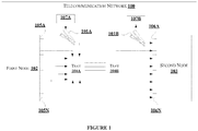
- FIG. 1 shows an Optical Fiber Communication (OFC) network 100 architecture in a central office, for identifying connectivity between nodes of the OFC network 100.
- the OFC network 100 comprises a transducer device 101A, a transducer device 101B, a first node 102, a second node 103, a first tray 104A, a second tray 104B, a transmitting port 105A, ..., a transmitting port 105N, a receiving port 106A, ..., a receiving port 106N, an ultrasound communicator 107A and an ultrasound communicator 107B.
- the transducer device 101A and a transducer device 101B may be represented together as a transducer device 101 in the present disclosure.
- the first node 102 and the second node 103 may be an Optical Distribution Frame (ODF), a transmission rack or the like.
- the OFC network 100 may be formed between a first ODF and a second ODF of the central office, a transmission rack and an ODF, or between any other entities of the central office.
- the tray 104 is used for grouping the FO patch cords at the first node 102 and the second node 103.
- the FO patch cords are wired from the first tray 104A to the second tray 104B.
- the FO patch cords may be wired beneath tiles of the central office.
- the ultrasound communicator (107A) and the ultrasound communicator (107B) may be represented together as an ultrasound communicator (107).
- the ultrasound communicator (107A) may be associated with the transducer device (101A).
- the ultrasound communicator (107B) may be associated with the transducer device (101B).
- the transmitting port 105A, ..., the transmitting port 105N may be collectively represented as one or more transmitting ports 105.
- the receiving port 106A, ..., the receiving port 106N may be collectively represented as one or more receiving port 106 in the present disclosure.
- a FO patch cord is connected to each of the one or more transmitting port 105.
- each of the FO patch cord is connected to corresponding receiving port 106.
- the transducer device 101A is connected to a FO patch cord corresponding to a faulty port.
- the faulty port may be considered as the transmitting port 105, as the transducer device 101A is used to transmit ultrasound signals from faulty port end of the OFC network 100 to another end of the OFC network 100.
- the transmitting port 105A may be considered as a faulty port.
- ports on the other end of the OFC network 100 may be considered as receiving ports 106, as the ultrasound signal is received by the transducer device 101B at the other end of the OFC network 100.
- the transducer device 101A is clipped to the FO patch cord of the transmitting port 105.
- the transducer device 101A transmits ultrasound signals through the FO patch cord.
- the transducer device 101A is clipped to an outer jacket (not shown in figure) of the FO patch cord for transmitting the ultrasound signal.
- the ultrasound signals may be transmitted through a core or cladding of the FO patch cord.
- the device 101B is clipped to a FO patch cord connected to a receiving port 106A.
- the transducer device 101B may be connected to a FO patch cord connected to each of the one or more receiving ports 106 consecutively until the transducer device 101B receives the ultrasound signals transmitted by the transducer device 101A.
- the transducer device 101B When the transducer device 101B receives the ultrasound signals, from a FO patch cord, the transducer device 101B identifies a port connected to the FO patch cord as the receiving port 106A. Thus, connectivity between the one or more transmitting ports 105 and corresponding receiving port among the one or more receiving ports 105 is identified.
- FIG. 2 shows an exemplary diagram of the connectivity identification system for identifying connectivity between nodes of the OFC network 100.
- the connectivity identification system comprises the transducer device 101 and the ultrasound communicator 107.
- the transducer device 101 represents a clip for clipping to the FO patch cord.
- the transducer device 101 comprises a probe 201. Further, the transducer device 101 may be associated with the ultrasound communicator 107.
- the transducer device 101 can be configured as an ultrasound transmitting device in one instance and as an ultrasound receiving device in another instance. When the transducer device 101 is configured as the transmitting device, the ultrasound communicator 107 is configured to generate electrical signals for transmitting corresponding ultrasound signals.
- the ultrasound communicator 107 is configured to detect ultrasound signals and process the ultrasound signals to identify connectivity between nodes of the OFC network 100.
- the probe 201 acts as an ultrasound injection probe when the transducer device 101 is configured as a transmitting device.
- the probe 201 acts as a detection probe when the transducer device is configured as a receiving device.
- the ultrasound communicator 107 When the transducer device 101 is configured as an ultrasound transmitting device, the ultrasound communicator 107 generates electrical signals. Then, the electrical signals are provided to the probe 201, where the probe 201 is inserted in the outer jacket of the FO patch cord.
- the probe 201 acts as a transducer, which converts electrical signals into mechanical vibrations.
- the mechanical vibrations propagate through the outer jacket of the FO patch cord for identifying connectivity between nodes of the OFC network 100.
- the mechanical vibrations are the ultrasound signals.
- the ultrasound communicator 107 receives the electrical signals.
- the transducer device 101 is connected to a FO patch cord, and the probe 201 is inserted into the outer jacket of the FO patch cord.
- the probe 201 acts as a transducer and receives mechanical vibrations from the FO patch cord. Further, the probe 201 converts the mechanical vibrations into electrical signals and provides the electrical signals to the ultrasound communicator 107.
- the ultrasound communicator 107 receives the electrical signals from the probe 201 and processes the electrical signals for identifying connectivity between nodes of the OFC network 100.
- FIG. 3 shows a block diagram of an ultrasound communicator 107 for identifying connectivity between nodes in an OFC network 100.
- the ultrasound communicator 107 comprises a transceiver unit 301 and a control unit 302.
- the transceiver unit 301 can be configured to transmit electrical signals and receive electrical signals.
- the control unit 302 configures the transceiver to transmit electrical signals when the transducer device 101 is connected to the first node 102.
- the control unit 302 configures the transceiver to receive electrical signals when the transducer device 101 is connected to the second node 103.
- the transceiver unit 301 may include, but is not limited to, a signal generator, a signal amplifier, an electrical transmitter, a signal conditioner, one or more band pass filters, a code detector and an ultrasound receiver.
- a signal generator When the transceiver is configured as a transmitter, the signal generator, the signal amplifier, and the transmitter are activated.
- the signal conditioner, the one or more band pass filters, the code detector and the signal receiver are activated.
- the signal generator generates electrical signals of a predefined frequency and amplitude.
- the signal amplifier amplifies the electrical signal.
- the transducer device 101 converts the electrical signals into mechanical vibrations and the mechanical vibrations are transmitted into the outer jacket of the FO patch cord.
- the transducer device 101 is also used to convert ultrasound signals back to electrical signals.
- the signal conditioner processes the electrical signals converted by the transducer device 101.
- the one or more band pass filters are used to allow a predefined band of frequencies through the filter.
- FIG. 4 shows an exemplary block diagram of a control unit 302 illustrating internal architecture of the control unit 302 for identifying connectivity between nodes in a OFC network 100.
- the control unit 302 may include at least one Central Processing Unit (“CPU” or “processor”) 403 and a memory 402 storing instructions executable by the at least one processor 403.
- the processor 403 may comprise at least one data processor for executing program components for executing user or system-generated requests.
- the memory 402 is communicatively coupled to the processor 403.
- the control unit 302 further comprises an Input/Output (I/O) interface 401.
- the I/O interface 401 is coupled with the processor 403 through which an input signal or/and an output signal is communicated.
- data 404 may be stored within the memory 402.
- the data 404 may include, for example, unique identifier 405, port data 406, FO patch cord data 407 and other data 408.
- the unique identifier 405 comprises a set of data which is unique to each of the FO patch cord connected between a transmitting port among the one or more transmitting ports 105 and a receiving port among the one or more receiving ports 106.
- the unique identifier 405 may be a set of randomly generated codes, random codes that may be present in a predefined list of codes, numeric data, alpha numeric data, or the like.
- the port data 406 may include, but are not limited to, number of ports, bit rate of port and bandwidth capacity of port.
- the FO patch cord data 407 may include, but are not limited to, channel capacity, channel gain, loss identifier in the FO patch cord, FO patch cord type, FO patch cord length, and FO patch cord number.
- the other data 408 may include, but are not limited to, OFC network 100 architecture type, type of encoding the unique identifier, and information of first node 102 and the second node 102.
- the data 404 in the memory 402 is processed by modules 409 of the control unit 302.
- the term module refers to an application specific integrated circuit (ASIC), an electronic circuit, a field-programmable gate arrays (FPGA), Programmable System-on-Chip (PSoC), a combinational logic circuit, and/or other suitable components that provide the described functionality.
- ASIC application specific integrated circuit
- FPGA field-programmable gate arrays
- PSoC Programmable System-on-Chip
- a combinational logic circuit and/or other suitable components that provide the described functionality.
- the modules 409 when configured with the functionality defined in the present disclosure will result in a novel hardware.
- the modules 409 may include, for example, a communication module 410, a configuration module 411, an identifier generation module 412, a demodulation module 413, a port identification module 414 and other modules 415. It will be appreciated that such aforementioned modules 409 may be represented as a single module or a combination of different modules.
- the communication module 410 may be used to communicate instructions to the transceiver unit 301. Further, the communication module 410 is configured to receive electrical signal from the transceiver unit 301. Also, the communication module 410 is configured to transmit the unique identifier to one or more devices similar to the device 100. Referring to Figure 1 , the transducer device 101A may be configured to transmit the ultrasound signals. The transducer device 101B may be configured to receive the ultrasound signals. Further, the first ultrasound communicator 107A transmits the unique identifier to the second ultrasound communicator 107B. The unique identifier may be transmitted over wired means or wireless means to a communication module 410 associated the one or more transducer devices.
- the configuration module 411 may configure the transducer device 100 either to transmit ultrasound signals or receive ultrasound signals.
- the configuration module 411 configures operation mode of the device 101 based on connection of the transducer device 101.
- the configuration module 411 configures the transducer device 100 to transmit ultrasound signals.
- the configuration module 411 configures the transducer device 101 to receive ultrasound signals.
- the configuration module 411 may configure the device 101 either to transmit or receive ultrasound signals upon receiving inputs from a user.
- the configuration module 411 instructs the transceiver to transmit ultrasound signals of a predefined frequency.
- the identifier generation module 412 may generate an identifier unique to each FO patch cord connected to the one or more transmitting ports (first node).
- the identifier may be a set of randomly generated codes, random codes that may be present in a predefined list of codes, numeric data, alpha numeric data, or the like. Further, the identifier generated may correspond to a predefined frequency. Thus, for a predefined frequency, a plurality of unique identifiers can be generated.
- the identifier generated for a device 101 configured in transmission mode is communicated by the communication module 410 to the device 100 configured in reception mode.
- the communication module 410 modulates the identifier with the ultrasound signals and the modulated ultrasound signals are transmitted.
- the demodulation module 413 may receive electrical signals from a transceiver unit 301 of a transducer device 101 among the one or more devices configured to receive the ultrasound signals. Further, the demodulation module 413 demodulates the electrical signals to retrieve the identifier. The demodulation of the electrical signals is performed at an end of the OFC network 100 where the receiving port 106 has to be identified. Referring to Figure 1 , the demodulation of the electrical signals is performed at the second node 103.
- the port identification module 414 may receive the demodulated identifier from the demodulation module 413. Also, the port identification module 414 receives the identifier from a transducer device 101A (in one instance) configured to transmit ultrasound signals. The port identification module 414 compares the demodulated identifier with the identifier received from the transducer device 101A. When the demodulated identifier matches the identifier received from the transducer device 101B, the port identification module 414 identifies a port connected to the FO patch cord to which the transducer device 101B (in one instance) is connected, as the receiving port 106A (in one instance).
- the other modules 415 may include a notification unit.
- the notification unit may notify the user when the demodulated identifier matches the identifier received from the transducer device 101A.
- the other modules may further include a user interface module.
- the user interface module may be used to receive information regarding length of the FO patch cord, obstacles in ultrasound signals transmission, transmission gain parameters, and the like.
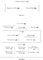
- Figure 5 shows a flow chart illustrating a method for identifying connectivity between nodes in an OFC network 100, in accordance with some embodiments of the present disclosure.
- the method 500 may comprise one or more steps for identifying connectivity between nodes in a OFC network 100, in accordance with some embodiments of the present disclosure.
- the method 500 may be described in the general context of computer executable instructions.
- computer executable instructions can include routines, programs, objects, components, data structures, procedures, modules, and functions, which perform particular functions or implement particular abstract data types.
- step 501 transmitting an ultrasound signal modulated with a unique identifier through the outer jacket of the FO patch cord among a plurality of FO patch cords, by the first transducer device 101A.
- step 502 receiving the ultrasound signal from an outer jacket of one of FO patch cord among the plurality of FO patch cords, by the second transducer device 101B.
- step 503 demodulating electrical signals corresponding to the ultrasound signal received by the second transducer device 101B to retrieve the unique identifier, by the demodulation unit 413 of the second ultrasound communicator 107B.
- step 504 identifying the receiving port based on the demodulated unique identifier, by the port identification unit 414 of the second ultrasound communicator 107B.
- the method steps 501 to 504 are illustrated in detail with an example below: Referring to Figure 1 , consider a scenario where the transmitting port 105A is faulty. Thus, there is a need to replace a FO patch cord connecting the transmitting port 105A and a port among the one or more receiving port 106. Let a first transducer device 101A be clipped to the FO patch cord among a plurality of FO patch cords, connected to the transmitting port 105A. For illustration, let us consider that, at the first node 102, the FO patch cords are placed in the first tray 104A. Further, the FO patch cords are wired to the second node 103.
- the configuration module 410 of the first ultrasound communicator 107A configures the first transducer device 101A as a transmitting device, i.e., the first transducer device 101A is configured to transmit ultrasound signals. Further, the control unit 302 of the first ultrasound communicator 107A determines the port data and the FO patch cord data to determine characteristics for transmitting the ultrasound signals. The characteristics of the ultrasound signals may include, but are not limited to, frequency of the ultrasound signal, amplitude of the ultrasound signal, and phase of the ultrasound signal. Then, the control unit 302 generates a unique identifier for modulating the ultrasound signals with the unique identifier. Once the ultrasound signals are modulated with the unique identifier, the control unit 302 of the first ultrasound communicator 107A configures the first transducer device 101A to transmit the modulated ultrasound signals through the outer jacket of the FO patch cord.
- a second transducer device 101B at the second node 103 of the OFC network 100 The FO patch cords are collected by the second tray 104B associated with the second node 103.
- the second device 101B is clipped to a FO patch cord corresponding to the receiving port 106A.
- the second transducer device is clipped to each of the plurality of FO patch cords placed in the second tray 104B consequently, for identifying the receiving port 106.
- receiving port 106A corresponds to the transmitting port 105A.
- the second ultrasound communicator 107B receives the unique identifier from the first ultrasound communicator 107A through an alternate communication channel.
- the alternate channel may include wired or wireless means.
- the second transducer device 101B receives the ultrasound signals from a FO patch cord among the plurality of FO patch cords. Then, the second ultrasound communicator 107B receives the electrical signals from the second transducer device 101B. The second ultrasound communicator 107B demodulates the electrical signals to retrieve the unique identifier. Further, the second ultrasound communicator 107B compares the demodulated unique identifier with the unique identifier received from the first ultrasound communicator 107A through the alternate channel. When the demodulated unique identifier matches the unique identifier received from the first ultrasound communicator 107A, the second ultrasound communicator 107B identifies a port connected to the FO patch cord. Further, the second ultrasound communicator 107B identifies the port as the receiving port 106A thereby identifying connectivity between the transmitting port 105A and the receiving port 106A.
- the ultrasound communicator 107 may comprise a user interface unit.
- the user interface unit may be used to receive inputs from the user.
- the inputs may include information on length of the FO patch cord, mode of operation of the device 101, FO patch cord data, port data, and OFC network architecture type.
- the transducer device 101 may undergo a testing. During testing, the transducer device 101 may be configured to transmit predefined frequencies based on the length of the FO patch cord data 407. Further, the transducer device 100 may be subjected to calibration based on results obtained during testing of the device 100. In an embodiment, by using different frequencies and unique identifier for each frequency, a plurality of unique signals may be generated.
- the transducer device 101 may receive instructions from the user to store data related to the calibration. The instructions may be in a specific format.
- the transducer device 101 may determine type of FO patch cord based on signal attenuation.
- the transducer device 101 may transmit and receive a test signal through the FO patch cord. Then, the transducer device 101 may calculate signal attenuation by comparing power transmitted with power received. The transducer device 101 then determines type of FO patch cord by comparing the signal attenuation with a list of predetermined attenuation values corresponding to a FO patch cord among a plurality of FO patch cord.
- the first transducer device 101A acts as a transmitting device and the second transducer device 101B acts as a receiving device. Also, the first transducer device 101A may act as a receiving device and the second transducer device 101B may act as a transmitting device for determining connectivity between the ports of the first node 102 and the second node 103. Reversal of mode of operation of the first transducer device 101A and the second transducer device 101B may be performed for verification.
- the first transducer device 101A may comprise a transmitter only to transmit ultrasound signals and the second transducer device 101B may comprise a receiver only to receive the ultrasound signals.
- the present disclosure discloses a portable device for identifying connectivity between nodes of a OFC network.
- the device can be connected and removed, thus providing flexibility in operating the device.
- the device of the present disclosure transmits ultrasound signals to identify connectivity between nodes.
- the ultrasound signals do not interfere with optical signals.
- the proposed device utilizes existing architecture and thereby reduces cost and complexity.
- the device of the present disclosure may be clipped to a FO patch cord and can be removed easily.
- the device proves to adhere to space constraints requirements, unlike conventional systems which are permanently installed.
- the cost associated with the device is less as compared to traditional systems.
Landscapes
- Physics & Mathematics (AREA)
- Engineering & Computer Science (AREA)
- Computer Networks & Wireless Communication (AREA)
- Signal Processing (AREA)
- Electromagnetism (AREA)
- General Physics & Mathematics (AREA)
- Chemical & Material Sciences (AREA)
- Analytical Chemistry (AREA)
- Optics & Photonics (AREA)
- Computing Systems (AREA)
- Ultra Sonic Daignosis Equipment (AREA)
Claims (13)
- Konnektivitätsidentifizierungssystem zum Identifizieren von Konnektivität in einem Glasfaser-Kommunikationsnetzwerk (Optical Fiber Communication, OFC) (100), umfassend einen ersten Knoten (102) und einen zweiten Knoten (103), das Konnektivitätsidentifizierungssystem umfassend;
einen Ultraschallkommunikator (107); und
eine Wandlervorrichtung (101), die kommunikativ mit dem Ultraschallkommunikator (107) verbunden ist, wobei,
wenn die Wandlervorrichtung (101) mit dem ersten Knoten (102) verbunden ist, der Ultraschallkommunikator (107) zu Folgendem konfiguriert ist:Erzeugen einer eindeutigen Kennung entsprechend jedem Glasfaser-Patchkabel (Fiber Optic, FO), das mit einem Sendeanschluss (105) des ersten Knotens (102) verbunden ist;Senden eines Ultraschallsignals, das mit der eindeutigen Kennung durch die Wandlervorrichtung (101) moduliert ist, durch einen äußeren Mantel des FO-Patchkabels unter einer Vielzahl von FO- Patchkabeln, die zwischen dem Sendeanschluss (105) des ersten Knotens (102) und einem Empfangsanschluss (106) des zweiten Knotens (103) verbunden ist, wobei eine Frequenz des Ultraschallsignals ausgewählt ist aus einem Satz vordefinierter Frequenzen ausgewählt wird, und wobei das Ultraschallsignal mit der ausgewählten Frequenz basierend auf einem oder mehreren Parametern des Sendeanschlusses (105), einem oder mehreren Parametern des Empfangsanschlusses (106) und einem oder mehreren Parametern des FO-Patchkabels übertragen wird, und wobei die erzeugte eindeutige Kennung der ausgewählten Frequenz entspricht; undSenden der eindeutigen Kennung über ein drahtloses Signal an den Empfangsanschluss des zweiten Knotens (103); und wobeiwenn die Wandlervorrichtung (101) mit dem zweiten Knoten (103) verbunden ist, der Ultraschallkommunikator (107) zu Folgendem konfiguriert ist:Empfangen des Ultraschallsignals von der Wandlervorrichtung (101), wobei die Wandlervorrichtung (101) das Ultraschallsignal von einem äußeren Mantel von einem der Vielzahl von FO-Patchkabeln empfängt;Empfangen des drahtlosen Signals von der Wandlervorrichtung (101), wobei das empfangene drahtlose Signal die eindeutige Kennung umfasst;Demodulieren des Ultraschallsignals, um die eindeutige Kennung abzurufen; und Vergleichen der eindeutigen Kennung, die über das drahtlose Signal empfangen wird mit der eindeutigen Kennung, die durch Demodulation des Ultraschallsignals abgerufen wird; und Identifizieren des Empfangsanschlusses (106) basierend auf dem Vergleich. - Konnektivitätsidentifizierungssystem nach Anspruch 1, wobei der Ultraschallkommunikator (107) eine Sendeempfängereinheit (301) und eine Steuereinheit (302) umfasst; optional wobei die Sendeempfängereinheit (301) mindestens eines von einem Signalgenerator, einem Signalverstärker, einem Wandler, einem Ultraschallsender, einem Signalformer, einem oder mehrere Bandpassfilter, einem Code-Detektor und einem Ultraschallempfänger umfasst.
- Konnektivitätsidentifizierungssystem nach Anspruch 1 oder 2, wobei die eindeutige Kennung zufällige eindeutige Codes und/oder alphanumerische Daten umfasst.
- Konnektivitätsidentifizierungssystem nach Anspruch 1, 2 oder 3, wobei, wenn die Wandlervorrichtung (101) mit dem ersten Knoten (102) verbunden ist, die Wandlervorrichtung (101) die eindeutige Kennung an eine Wandlervorrichtung unter einer oder mehreren Wandlervorrichtungen sendet, die mit dem zweiten Knoten (103) verbunden sind; optional wobei die mit dem ersten Knoten verbundene Wandlervorrichtung (101) eine erste Wandlervorrichtung (101A) ist und die Wandlervorrichtung unter der einen oder den mehreren Wandlervorrichtungen, die mit dem zweiten Knoten verbunden sind, eine zweite Wandlervorrichtung (101B) ist, wobei die erste Wandlervorrichtung (101A) mit einem ersten Ultraschallkommunikator (107A) assoziiert ist und die zweite Wandlervorrichtung (101B) mit einem zweiten Ultraschallkommunikator (107B) assoziiert ist.
- Konnektivitätsidentifizierungssystem nach einem vorherigen Anspruch, wobei der eine oder die mehreren Parameter des FO-Patchkabels mindestens eines von einer Kanalkapazität, einer Kanalverstärkung, einer Verlustkennung in dem FO-Patchkabel, einem FO-Patchkabeltyp, einer FO-Patchkabellänge und einer FO-Patchkabelnummer umfassen; optional wobei die zweite Wandlervorrichtung (101B) an das eine der FO-Patchkabel geklemmt wird, um das Ultraschallsignal zu empfangen, während das FO-Patchkabel mit dem Empfangsanschluss (106) verbunden ist.
- Konnektivitätsidentifizierungssystem nach Anspruch 4, wobei der zweite Ultraschallkommunikator (107B) den Empfangsanschluss (106) identifiziert, wobei ein Identifizieren Folgendes umfasst:Empfangen der eindeutigen Kennung von der ersten Wandlervorrichtung (101A); Vergleichen der demodulierten eindeutigen Kennung mit der eindeutigen Kennung, die von der ersten Wandlervorrichtung (101A) empfangen wird; undBestimmen eines Anschlusses, der mit dem einen von FO-Patchkabel als Empfangsanschluss (106) verbunden ist, wenn die demodulierte eindeutige Kennung mit der eindeutigen Kennung übereinstimmt, die von der ersten Wandlervorrichtung (101A) empfangen wird; und optional wobei die erste Wandlervorrichtung (101A) an das FO-Patchkabel geklemmt ist, um das Ultraschallsignal zu senden, während das FO-Patchkabel mit dem Sendeanschluss (105) verbunden ist.
- Verfahren zum Identifizieren von Konnektivität in einem Glasfaser-Kommunikationsnetzwerk (Optical Fiber Communication, OFC) (100), umfassend einen ersten Knoten (102) und einen zweiten Knoten (103), das Verfahren umfassend:Erzeugen, durch ein Konnektivitätsidentifizierungssystem, einer eindeutigen Kennung entsprechend jedem Glasfaser-Patchkabel (Fiber Optic, FO), das mit einem Sendeanschluss (105) des ersten Knotens (102) verbunden ist;Senden, durch das Konnektivitätsidentifizierungssystem, eines Ultraschallsignals, das mit einer eindeutigen Kennung moduliert ist, durch einen äußeren Mantel des FO-Patchkabels unter einer Vielzahl von FO- Patchkabeln, die zwischen dem Sendeanschluss (105) des ersten Knotens (102) und einem Empfangsanschluss des zweiten Knotens (103) verbunden ist, wobei eine Frequenz des Ultraschallsignals ausgewählt ist aus einem Satz vordefinierter Frequenzen ausgewählt wird, und wobei das Ultraschallsignal mit der ausgewählten Frequenz basierend auf einem oder mehreren Parametern des Sendeanschlusses (105), einem oder mehreren Parametern des Empfangsanschlusses (106) und einem oder mehreren Parametern des FO-Patchkabels übertragen wird, und wobei die erzeugte eindeutige Kennung der ausgewählten Frequenz entspricht;Empfangen, durch das Konnektivitätsidentifizierungssystem, des Ultraschallsignals von einem äußeren Mantel von einem der FO-Patchkabel, die mit dem zweiten Knoten (103) verbunden sind;Empfangen, durch das Konnektivitätsidentifizierungssystem, des drahtlosen Signals von der Wandlervorrichtung (101), wobei das empfangene drahtlose Signal die eindeutige Kennung umfasst;Demodulieren, durch das Konnektivitätsidentifizierungssystem, des Ultraschallsignals, um die eindeutige Kennung abzurufen;Vergleichen, durch das Konnektivitätsidentifizierungssystem, der eindeutigen Kennung, die über das drahtlose Signal empfangen wird mit der eindeutigen Kennung, die durch Demodulation des Ultraschallsignals abgerufen wird; undIdentifizieren, durch das Konnektivitätsidentifizierungssystem, des Empfangsanschlusses (106) basierend auf dem Vergleich.
- Verfahren nach Anspruch 7, wobei die eindeutige Kennung zufällige eindeutige Codes und/oder alphanumerische Daten umfasst.
- Verfahren nach Anspruch 7 oder 8, wobei das Ultraschallsignal mit einer vorbestimmten Frequenz basierend auf einem oder mehreren Parametern des ersten Knotens (102), einem oder mehreren Parametern des zweiten Knotens (103) und einem oder mehreren Parametern des FO-Patchkabels gesendet wird.
- Verfahren nach Anspruch 9, wobei der eine oder die mehreren Parameter des FO-Patchkabels mindestens eines von einer Kanalkapazität, einer Kanalverstärkung, einer Verlustkennung in dem FO-Patchkabel, einem FO-Patchkabeltyp, einer FO-Patchkabellänge und einer FO-Patchkabelnummer umfassen.
- Verfahren nach einem der Ansprüche 7-10, wobei der Schritt eines Sendens durch eine erste Wandlervorrichtung (101A) ausgeführt wird, die mit einem ersten Ultraschallkommunikator (107A) assoziiert ist, die Schritte eines Empfangens durch eine zweite Wandlervorrichtung (101B) ausgeführt werden und der Schritt eines Demodulierens und Identifizierens durch einen zweiten Ultraschallkommunikator (107B) ausgeführt wird, der mit der zweiten Wandlervorrichtung (101B) assoziiert ist.
- Verfahren nach einem der Ansprüche 7-11, ferner umfassend ein Senden, durch die erste Wandlervorrichtung (101A), der eindeutigen Kennung an eines der Vielzahl von FO-Patchkabeln und Empfangen, durch die zweite Wandlervorrichtung (101B), der eindeutigen Kennung von der ersten Wandlervorrichtung (101A), um den Empfangsanschluss (106) zu identifizieren.
- Verfahren nach Anspruch 12, wobei ein Identifizieren ferner Folgendes umfasst:Vergleichen der demodulierten eindeutigen Kennung mit der eindeutigen Kennung, die von der ersten Wandlervorrichtung (101A) empfangen wird; undBestimmen eines Anschlusses, der mit dem einen von FO-Patchkabel als Empfangsanschluss (106) verbunden ist, wenn die demodulierte eindeutige Kennung mit der eindeutigen Kennung übereinstimmt, die von der ersten Wandlervorrichtung (101A) empfangen wird.
Applications Claiming Priority (1)
| Application Number | Priority Date | Filing Date | Title |
|---|---|---|---|
| IN201741007852 | 2017-03-06 |
Publications (2)
| Publication Number | Publication Date |
|---|---|
| EP3372976A1 EP3372976A1 (de) | 2018-09-12 |
| EP3372976B1 true EP3372976B1 (de) | 2020-06-10 |
Family
ID=58669573
Family Applications (1)
| Application Number | Title | Priority Date | Filing Date |
|---|---|---|---|
| EP17163926.3A Active EP3372976B1 (de) | 2017-03-06 | 2017-03-30 | Verfahren und system zur identifizierung von konnektivität in einem glasfaserübertragungsnetz (ofc) |
Country Status (2)
| Country | Link |
|---|---|
| US (1) | US10069569B1 (de) |
| EP (1) | EP3372976B1 (de) |
Families Citing this family (1)
| Publication number | Priority date | Publication date | Assignee | Title |
|---|---|---|---|---|
| FI4037204T3 (fi) * | 2021-01-29 | 2024-04-23 | Jio Platforms Ltd | Järjestelmä ja menetelmä kuidun kapasiteetin automaattiseen tunnistamiseen |
Family Cites Families (10)
| Publication number | Priority date | Publication date | Assignee | Title |
|---|---|---|---|---|
| US5394503A (en) | 1993-10-08 | 1995-02-28 | Data Switch Corporation | Optical fiber connection monitoring apparatus, patch panel control system and method of using same |
| US6002331A (en) | 1998-07-20 | 1999-12-14 | Laor; Herzel | Method and apparatus for identifying and tracking connections of communication lines |
| JP4790722B2 (ja) | 2004-11-03 | 2011-10-12 | パンドウィット・コーポレーション | パッチパネルのパッチコード・ドキュメンテーションおよびその改訂のための方法および装置について |
| DE102007039294A1 (de) | 2007-08-20 | 2009-04-02 | Zellner Gmbh | Identifizierbares Kabel |
| US8092249B2 (en) * | 2009-02-19 | 2012-01-10 | Commscope Inc. Of North Carolina | Patch panel cable information detection systems and methods |
| CN102598705B (zh) * | 2009-06-29 | 2015-06-17 | 北卡罗来纳科姆斯科普公司 | 接插板、接插板系统和显示接插线连接信息的方法 |
| US9538262B2 (en) * | 2009-08-21 | 2017-01-03 | Commscope, Inc. Of North Carolina | Systems, equipment and methods for automatically tracking cable connections and for identifying work area devices and related methods of operating communications networks |
| US8391321B2 (en) * | 2010-06-10 | 2013-03-05 | Broadcom Corporation | Method and system for patch panel port identification and verification |
| GB2505090A (en) * | 2011-05-05 | 2014-02-19 | Commscope Inc | Intelligent patching systems using acoustic control signals and related equipment and methods |
| US8606972B2 (en) | 2011-11-30 | 2013-12-10 | International Business Machines Corporation | Cable identification using data traffic activity information |
-
2017
- 2017-03-20 US US15/463,401 patent/US10069569B1/en active Active
- 2017-03-30 EP EP17163926.3A patent/EP3372976B1/de active Active
Non-Patent Citations (1)
| Title |
|---|
| None * |
Also Published As
| Publication number | Publication date |
|---|---|
| US10069569B1 (en) | 2018-09-04 |
| US20180254830A1 (en) | 2018-09-06 |
| EP3372976A1 (de) | 2018-09-12 |
Similar Documents
| Publication | Publication Date | Title |
|---|---|---|
| US10469187B2 (en) | Systems and methods for detecting passive inter-modulation (PIM) interference in cellular networks | |
| CN112787716B (zh) | 故障检测方法及装置、电子设备、计算机可读介质 | |
| JP4712893B2 (ja) | 端末ネットワーク装置をグループ化する方法および装置 | |
| US9647758B2 (en) | Cabling connectivity monitoring and verification | |
| JP4416800B2 (ja) | 移動通信端末を利用したアンテナシステム遠隔測定監視装置及びその方法 | |
| US11184692B2 (en) | Systems and methods for measurement of optical parameters in an optical network | |
| US20210218469A1 (en) | Submarine cable fault determining method and apparatus | |
| WO2007005970B1 (en) | Optical autodiscovery for automated logical and physical connectivity check between optical modules | |
| CN103957220A (zh) | 一种基于变频声波的数据传输方法及系统 | |
| EP3372976B1 (de) | Verfahren und system zur identifizierung von konnektivität in einem glasfaserübertragungsnetz (ofc) | |
| US11128598B1 (en) | Methods and systems for discovering media access control (MAC) addresses | |
| US10492089B2 (en) | Method for testing a radio communication device to be tested of a gateway in a set of gateways | |
| CN110769396B (zh) | 机器人连接网络的方法、系统及终端设备 | |
| US10484895B2 (en) | Wireless data concentrator systems and methods | |
| US8855486B2 (en) | Remotely controlled fiber testing method | |
| Song et al. | Cluster-based Method for Eavesdropping Identification and Localization in Optical Links | |
| EP1745584B1 (de) | Eingebettete kanalanalyse für ein hf-datenmodem | |
| CN113411788B (zh) | 具有未配网通信机制的蓝牙网格网络系统及其通信方法 | |
| KR100545290B1 (ko) | 망 장애 판별을 위한 기지국 및 중계기 통합 관리 방법 | |
| US20200186457A1 (en) | Test System For Rack And Electronic Devices Disposed In The Rack And Method Thereof | |
| CN113852430B (zh) | 用户环境下的蓝牙设备性能测试系统及测试方法 | |
| KR101533982B1 (ko) | 광신호 루프백시험장치 및 그 장치의 동작 방법 | |
| CN117222044A (zh) | 设备连接方法、设备、系统和介质 | |
| CN114124533A (zh) | 数据拦截方法、装置、电子设备和计算机可读介质 | |
| CN109672509A (zh) | 盾构机舱内通信方法及通信系统 |
Legal Events
| Date | Code | Title | Description |
|---|---|---|---|
| PUAI | Public reference made under article 153(3) epc to a published international application that has entered the european phase |
Free format text: ORIGINAL CODE: 0009012 |
|
| STAA | Information on the status of an ep patent application or granted ep patent |
Free format text: STATUS: THE APPLICATION HAS BEEN PUBLISHED |
|
| AK | Designated contracting states |
Kind code of ref document: A1 Designated state(s): AL AT BE BG CH CY CZ DE DK EE ES FI FR GB GR HR HU IE IS IT LI LT LU LV MC MK MT NL NO PL PT RO RS SE SI SK SM TR |
|
| AX | Request for extension of the european patent |
Extension state: BA ME |
|
| STAA | Information on the status of an ep patent application or granted ep patent |
Free format text: STATUS: REQUEST FOR EXAMINATION WAS MADE |
|
| 17P | Request for examination filed |
Effective date: 20190312 |
|
| RBV | Designated contracting states (corrected) |
Designated state(s): AL AT BE BG CH CY CZ DE DK EE ES FI FR GB GR HR HU IE IS IT LI LT LU LV MC MK MT NL NO PL PT RO RS SE SI SK SM TR |
|
| STAA | Information on the status of an ep patent application or granted ep patent |
Free format text: STATUS: EXAMINATION IS IN PROGRESS |
|
| 17Q | First examination report despatched |
Effective date: 20190729 |
|
| GRAP | Despatch of communication of intention to grant a patent |
Free format text: ORIGINAL CODE: EPIDOSNIGR1 |
|
| STAA | Information on the status of an ep patent application or granted ep patent |
Free format text: STATUS: GRANT OF PATENT IS INTENDED |
|
| INTG | Intention to grant announced |
Effective date: 20200102 |
|
| GRAS | Grant fee paid |
Free format text: ORIGINAL CODE: EPIDOSNIGR3 |
|
| GRAA | (expected) grant |
Free format text: ORIGINAL CODE: 0009210 |
|
| STAA | Information on the status of an ep patent application or granted ep patent |
Free format text: STATUS: THE PATENT HAS BEEN GRANTED |
|
| AK | Designated contracting states |
Kind code of ref document: B1 Designated state(s): AL AT BE BG CH CY CZ DE DK EE ES FI FR GB GR HR HU IE IS IT LI LT LU LV MC MK MT NL NO PL PT RO RS SE SI SK SM TR |
|
| REG | Reference to a national code |
Ref country code: GB Ref legal event code: FG4D |
|
| REG | Reference to a national code |
Ref country code: CH Ref legal event code: EP Ref country code: AT Ref legal event code: REF Ref document number: 1279572 Country of ref document: AT Kind code of ref document: T Effective date: 20200615 |
|
| REG | Reference to a national code |
Ref country code: DE Ref legal event code: R096 Ref document number: 602017017871 Country of ref document: DE |
|
| REG | Reference to a national code |
Ref country code: IE Ref legal event code: FG4D |
|
| REG | Reference to a national code |
Ref country code: LT Ref legal event code: MG4D |
|
| PG25 | Lapsed in a contracting state [announced via postgrant information from national office to epo] |
Ref country code: LT Free format text: LAPSE BECAUSE OF FAILURE TO SUBMIT A TRANSLATION OF THE DESCRIPTION OR TO PAY THE FEE WITHIN THE PRESCRIBED TIME-LIMIT Effective date: 20200610 Ref country code: SE Free format text: LAPSE BECAUSE OF FAILURE TO SUBMIT A TRANSLATION OF THE DESCRIPTION OR TO PAY THE FEE WITHIN THE PRESCRIBED TIME-LIMIT Effective date: 20200610 Ref country code: FI Free format text: LAPSE BECAUSE OF FAILURE TO SUBMIT A TRANSLATION OF THE DESCRIPTION OR TO PAY THE FEE WITHIN THE PRESCRIBED TIME-LIMIT Effective date: 20200610 Ref country code: GR Free format text: LAPSE BECAUSE OF FAILURE TO SUBMIT A TRANSLATION OF THE DESCRIPTION OR TO PAY THE FEE WITHIN THE PRESCRIBED TIME-LIMIT Effective date: 20200911 Ref country code: NO Free format text: LAPSE BECAUSE OF FAILURE TO SUBMIT A TRANSLATION OF THE DESCRIPTION OR TO PAY THE FEE WITHIN THE PRESCRIBED TIME-LIMIT Effective date: 20200910 |
|
| REG | Reference to a national code |
Ref country code: NL Ref legal event code: MP Effective date: 20200610 |
|
| PG25 | Lapsed in a contracting state [announced via postgrant information from national office to epo] |
Ref country code: RS Free format text: LAPSE BECAUSE OF FAILURE TO SUBMIT A TRANSLATION OF THE DESCRIPTION OR TO PAY THE FEE WITHIN THE PRESCRIBED TIME-LIMIT Effective date: 20200610 Ref country code: LV Free format text: LAPSE BECAUSE OF FAILURE TO SUBMIT A TRANSLATION OF THE DESCRIPTION OR TO PAY THE FEE WITHIN THE PRESCRIBED TIME-LIMIT Effective date: 20200610 Ref country code: BG Free format text: LAPSE BECAUSE OF FAILURE TO SUBMIT A TRANSLATION OF THE DESCRIPTION OR TO PAY THE FEE WITHIN THE PRESCRIBED TIME-LIMIT Effective date: 20200910 Ref country code: HR Free format text: LAPSE BECAUSE OF FAILURE TO SUBMIT A TRANSLATION OF THE DESCRIPTION OR TO PAY THE FEE WITHIN THE PRESCRIBED TIME-LIMIT Effective date: 20200610 |
|
| REG | Reference to a national code |
Ref country code: AT Ref legal event code: MK05 Ref document number: 1279572 Country of ref document: AT Kind code of ref document: T Effective date: 20200610 |
|
| PG25 | Lapsed in a contracting state [announced via postgrant information from national office to epo] |
Ref country code: NL Free format text: LAPSE BECAUSE OF FAILURE TO SUBMIT A TRANSLATION OF THE DESCRIPTION OR TO PAY THE FEE WITHIN THE PRESCRIBED TIME-LIMIT Effective date: 20200610 Ref country code: AL Free format text: LAPSE BECAUSE OF FAILURE TO SUBMIT A TRANSLATION OF THE DESCRIPTION OR TO PAY THE FEE WITHIN THE PRESCRIBED TIME-LIMIT Effective date: 20200610 |
|
| PG25 | Lapsed in a contracting state [announced via postgrant information from national office to epo] |
Ref country code: RO Free format text: LAPSE BECAUSE OF FAILURE TO SUBMIT A TRANSLATION OF THE DESCRIPTION OR TO PAY THE FEE WITHIN THE PRESCRIBED TIME-LIMIT Effective date: 20200610 Ref country code: CZ Free format text: LAPSE BECAUSE OF FAILURE TO SUBMIT A TRANSLATION OF THE DESCRIPTION OR TO PAY THE FEE WITHIN THE PRESCRIBED TIME-LIMIT Effective date: 20200610 Ref country code: SM Free format text: LAPSE BECAUSE OF FAILURE TO SUBMIT A TRANSLATION OF THE DESCRIPTION OR TO PAY THE FEE WITHIN THE PRESCRIBED TIME-LIMIT Effective date: 20200610 Ref country code: IT Free format text: LAPSE BECAUSE OF FAILURE TO SUBMIT A TRANSLATION OF THE DESCRIPTION OR TO PAY THE FEE WITHIN THE PRESCRIBED TIME-LIMIT Effective date: 20200610 Ref country code: EE Free format text: LAPSE BECAUSE OF FAILURE TO SUBMIT A TRANSLATION OF THE DESCRIPTION OR TO PAY THE FEE WITHIN THE PRESCRIBED TIME-LIMIT Effective date: 20200610 Ref country code: AT Free format text: LAPSE BECAUSE OF FAILURE TO SUBMIT A TRANSLATION OF THE DESCRIPTION OR TO PAY THE FEE WITHIN THE PRESCRIBED TIME-LIMIT Effective date: 20200610 Ref country code: ES Free format text: LAPSE BECAUSE OF FAILURE TO SUBMIT A TRANSLATION OF THE DESCRIPTION OR TO PAY THE FEE WITHIN THE PRESCRIBED TIME-LIMIT Effective date: 20200610 Ref country code: PT Free format text: LAPSE BECAUSE OF FAILURE TO SUBMIT A TRANSLATION OF THE DESCRIPTION OR TO PAY THE FEE WITHIN THE PRESCRIBED TIME-LIMIT Effective date: 20201012 |
|
| PG25 | Lapsed in a contracting state [announced via postgrant information from national office to epo] |
Ref country code: SK Free format text: LAPSE BECAUSE OF FAILURE TO SUBMIT A TRANSLATION OF THE DESCRIPTION OR TO PAY THE FEE WITHIN THE PRESCRIBED TIME-LIMIT Effective date: 20200610 Ref country code: PL Free format text: LAPSE BECAUSE OF FAILURE TO SUBMIT A TRANSLATION OF THE DESCRIPTION OR TO PAY THE FEE WITHIN THE PRESCRIBED TIME-LIMIT Effective date: 20200610 Ref country code: IS Free format text: LAPSE BECAUSE OF FAILURE TO SUBMIT A TRANSLATION OF THE DESCRIPTION OR TO PAY THE FEE WITHIN THE PRESCRIBED TIME-LIMIT Effective date: 20201010 |
|
| REG | Reference to a national code |
Ref country code: DE Ref legal event code: R097 Ref document number: 602017017871 Country of ref document: DE |
|
| PLBE | No opposition filed within time limit |
Free format text: ORIGINAL CODE: 0009261 |
|
| STAA | Information on the status of an ep patent application or granted ep patent |
Free format text: STATUS: NO OPPOSITION FILED WITHIN TIME LIMIT |
|
| PG25 | Lapsed in a contracting state [announced via postgrant information from national office to epo] |
Ref country code: DK Free format text: LAPSE BECAUSE OF FAILURE TO SUBMIT A TRANSLATION OF THE DESCRIPTION OR TO PAY THE FEE WITHIN THE PRESCRIBED TIME-LIMIT Effective date: 20200610 |
|
| 26N | No opposition filed |
Effective date: 20210311 |
|
| PG25 | Lapsed in a contracting state [announced via postgrant information from national office to epo] |
Ref country code: SI Free format text: LAPSE BECAUSE OF FAILURE TO SUBMIT A TRANSLATION OF THE DESCRIPTION OR TO PAY THE FEE WITHIN THE PRESCRIBED TIME-LIMIT Effective date: 20200610 |
|
| PG25 | Lapsed in a contracting state [announced via postgrant information from national office to epo] |
Ref country code: MC Free format text: LAPSE BECAUSE OF FAILURE TO SUBMIT A TRANSLATION OF THE DESCRIPTION OR TO PAY THE FEE WITHIN THE PRESCRIBED TIME-LIMIT Effective date: 20200610 |
|
| REG | Reference to a national code |
Ref country code: CH Ref legal event code: PL |
|
| REG | Reference to a national code |
Ref country code: BE Ref legal event code: MM Effective date: 20210331 |
|
| PG25 | Lapsed in a contracting state [announced via postgrant information from national office to epo] |
Ref country code: CH Free format text: LAPSE BECAUSE OF NON-PAYMENT OF DUE FEES Effective date: 20210331 Ref country code: LU Free format text: LAPSE BECAUSE OF NON-PAYMENT OF DUE FEES Effective date: 20210330 Ref country code: LI Free format text: LAPSE BECAUSE OF NON-PAYMENT OF DUE FEES Effective date: 20210331 Ref country code: IE Free format text: LAPSE BECAUSE OF NON-PAYMENT OF DUE FEES Effective date: 20210330 |
|
| PG25 | Lapsed in a contracting state [announced via postgrant information from national office to epo] |
Ref country code: BE Free format text: LAPSE BECAUSE OF NON-PAYMENT OF DUE FEES Effective date: 20210331 |
|
| PG25 | Lapsed in a contracting state [announced via postgrant information from national office to epo] |
Ref country code: CY Free format text: LAPSE BECAUSE OF FAILURE TO SUBMIT A TRANSLATION OF THE DESCRIPTION OR TO PAY THE FEE WITHIN THE PRESCRIBED TIME-LIMIT Effective date: 20200610 |
|
| P01 | Opt-out of the competence of the unified patent court (upc) registered |
Effective date: 20230605 |
|
| PG25 | Lapsed in a contracting state [announced via postgrant information from national office to epo] |
Ref country code: HU Free format text: LAPSE BECAUSE OF FAILURE TO SUBMIT A TRANSLATION OF THE DESCRIPTION OR TO PAY THE FEE WITHIN THE PRESCRIBED TIME-LIMIT; INVALID AB INITIO Effective date: 20170330 |
|
| PG25 | Lapsed in a contracting state [announced via postgrant information from national office to epo] |
Ref country code: MK Free format text: LAPSE BECAUSE OF FAILURE TO SUBMIT A TRANSLATION OF THE DESCRIPTION OR TO PAY THE FEE WITHIN THE PRESCRIBED TIME-LIMIT Effective date: 20200610 |
|
| PG25 | Lapsed in a contracting state [announced via postgrant information from national office to epo] |
Ref country code: MT Free format text: LAPSE BECAUSE OF FAILURE TO SUBMIT A TRANSLATION OF THE DESCRIPTION OR TO PAY THE FEE WITHIN THE PRESCRIBED TIME-LIMIT Effective date: 20200610 |
|
| PG25 | Lapsed in a contracting state [announced via postgrant information from national office to epo] |
Ref country code: TR Free format text: LAPSE BECAUSE OF FAILURE TO SUBMIT A TRANSLATION OF THE DESCRIPTION OR TO PAY THE FEE WITHIN THE PRESCRIBED TIME-LIMIT Effective date: 20200610 |
|
| PGFP | Annual fee paid to national office [announced via postgrant information from national office to epo] |
Ref country code: GB Payment date: 20260209 Year of fee payment: 10 |
|
| PGFP | Annual fee paid to national office [announced via postgrant information from national office to epo] |
Ref country code: DE Payment date: 20260204 Year of fee payment: 10 |
|
| PGFP | Annual fee paid to national office [announced via postgrant information from national office to epo] |
Ref country code: FR Payment date: 20260209 Year of fee payment: 10 |