EP3372949B1 - Waffen und explosivstoffdetektor und detektionsverfahren - Google Patents
Waffen und explosivstoffdetektor und detektionsverfahren Download PDFInfo
- Publication number
- EP3372949B1 EP3372949B1 EP16861661.3A EP16861661A EP3372949B1 EP 3372949 B1 EP3372949 B1 EP 3372949B1 EP 16861661 A EP16861661 A EP 16861661A EP 3372949 B1 EP3372949 B1 EP 3372949B1
- Authority
- EP
- European Patent Office
- Prior art keywords
- antenna
- sensor
- disturbance
- detected
- area
- Prior art date
- Legal status (The legal status is an assumption and is not a legal conclusion. Google has not performed a legal analysis and makes no representation as to the accuracy of the status listed.)
- Active
Links
Images


Classifications
-
- F—MECHANICAL ENGINEERING; LIGHTING; HEATING; WEAPONS; BLASTING
- F41—WEAPONS
- F41H—ARMOUR; ARMOURED TURRETS; ARMOURED OR ARMED VEHICLES; MEANS OF ATTACK OR DEFENCE, e.g. CAMOUFLAGE, IN GENERAL
- F41H11/00—Defence installations; Defence devices
- F41H11/12—Means for clearing land minefields; Systems specially adapted for detection of landmines
-
- G—PHYSICS
- G01—MEASURING; TESTING
- G01V—GEOPHYSICS; GRAVITATIONAL MEASUREMENTS; DETECTING MASSES OR OBJECTS; TAGS
- G01V3/00—Electric or magnetic prospecting or detecting; Measuring magnetic field characteristics of the earth, e.g. declination, deviation
- G01V3/08—Electric or magnetic prospecting or detecting; Measuring magnetic field characteristics of the earth, e.g. declination, deviation operating with magnetic or electric fields produced or modified by objects or geological structures or by detecting devices
- G01V3/088—Electric or magnetic prospecting or detecting; Measuring magnetic field characteristics of the earth, e.g. declination, deviation operating with magnetic or electric fields produced or modified by objects or geological structures or by detecting devices operating with electric fields
-
- F—MECHANICAL ENGINEERING; LIGHTING; HEATING; WEAPONS; BLASTING
- F41—WEAPONS
- F41H—ARMOUR; ARMOURED TURRETS; ARMOURED OR ARMED VEHICLES; MEANS OF ATTACK OR DEFENCE, e.g. CAMOUFLAGE, IN GENERAL
- F41H11/00—Defence installations; Defence devices
- F41H11/12—Means for clearing land minefields; Systems specially adapted for detection of landmines
- F41H11/13—Systems specially adapted for detection of landmines
-
- F—MECHANICAL ENGINEERING; LIGHTING; HEATING; WEAPONS; BLASTING
- F41—WEAPONS
- F41H—ARMOUR; ARMOURED TURRETS; ARMOURED OR ARMED VEHICLES; MEANS OF ATTACK OR DEFENCE, e.g. CAMOUFLAGE, IN GENERAL
- F41H11/00—Defence installations; Defence devices
- F41H11/12—Means for clearing land minefields; Systems specially adapted for detection of landmines
- F41H11/13—Systems specially adapted for detection of landmines
- F41H11/136—Magnetic, electromagnetic, acoustic or radiation systems, e.g. ground penetrating radars or metal-detectors
-
- F—MECHANICAL ENGINEERING; LIGHTING; HEATING; WEAPONS; BLASTING
- F41—WEAPONS
- F41H—ARMOUR; ARMOURED TURRETS; ARMOURED OR ARMED VEHICLES; MEANS OF ATTACK OR DEFENCE, e.g. CAMOUFLAGE, IN GENERAL
- F41H11/00—Defence installations; Defence devices
- F41H11/12—Means for clearing land minefields; Systems specially adapted for detection of landmines
- F41H11/16—Self-propelled mine-clearing vehicles; Mine-clearing devices attachable to vehicles
-
- G—PHYSICS
- G01—MEASURING; TESTING
- G01V—GEOPHYSICS; GRAVITATIONAL MEASUREMENTS; DETECTING MASSES OR OBJECTS; TAGS
- G01V3/00—Electric or magnetic prospecting or detecting; Measuring magnetic field characteristics of the earth, e.g. declination, deviation
- G01V3/08—Electric or magnetic prospecting or detecting; Measuring magnetic field characteristics of the earth, e.g. declination, deviation operating with magnetic or electric fields produced or modified by objects or geological structures or by detecting devices
-
- G—PHYSICS
- G06—COMPUTING OR CALCULATING; COUNTING
- G06T—IMAGE DATA PROCESSING OR GENERATION, IN GENERAL
- G06T1/00—General purpose image data processing
- G06T1/0014—Image feed-back for automatic industrial control, e.g. robot with camera
Definitions
- This invention refers to a weapons and explosives detector and a method for detecting weapons and explosives More precisely, this invention refers to IED (Improvised Explosive Devices) detection when vehicles pass by, car bomb detection, land mine detection and/or weapon detection in urban areas and hideouts.
- IED Improvised Explosive Devices
- WO2015/044487 is described in the state of the art. It describes an electrostatic field sensor and a security system for inside spaces that can measure electrostatic fields and their variations through a metal conductor which acts as an antenna or capture probe. This probe is connected to an electronic circuit able to decode these changes in the electrostatic field around the antenna's metallic conductor.
- This system allows for measuring disturbances through a single antenna, and from there, deduce the presence of a person, distinguishing them from an animal or thing by measuring the disturbance itself on the single antenna.
- the system is conceived as a preventative alarm detector, by proximity, by detecting a disturbance in the transmission from the single electrode.
- this system is conceived as a security detector system and alarm, but it is not outlined as an explosives and weapons detector.
- the system set out in the WO2015/044487 document would need to be modified so that it can be used in an environment which is constantly under threat and with countermeasures made by the enemy.
- the document US2014/077993 outlines a pivotable block, where at least transmission and reception antennas are assembled for detecting improvised explosive devices, which are positioned in such a way that they illuminate at least one, same space, and a detection camera to confirm that it is facing the illuminated area through these transmission and reception antennas in such a way to be able to create an image of the area, as well as methods to control the direction of this pivotable block, which provoke a movement of the block, generating an examination of a part of the space with these detection methods.
- the US2009/182525 document also outlines a method that can include IED detection by detecting the presence of an IED's non-linear electronic component.
- the presence of the IED's non-linear electronic component can be detected by illuminating the device with a high-power microwave signal that contains multiple electromagnetic radiation radio frequencies and the reception of all and/or difference in frequency components that are made by interacting the signal illumination with a non-linear IED component and subsequently radiated.
- the document EP 1 754 983 A1 discloses or provide a technology relating to a detection-object-position-specifying device and a method for specifying a position of an object to be detected in a simple configuration without the necessity of a fixing device.
- the device for specifying a position of buried anti-personnel land mines includes a metal detection coil (sensor unit) mounted to a distal end portion of a supporting arm, a CCD camera mounted to the vicinity of a grip portion of the supporting arm, a personal computer (PC) as image analyzing means that imports information sent from the sensor unit and the CCD camera via a signal line and markers placed on the ground (GL).
- the CCD camera is fixed to the supporting arm so that the sensor unit and the markers can be included in a field of view simultaneously.
- an electric field signature detector for detecting and identifying objects that uses multiple electrostatic sensor nodes each having a passive sensing electrode whose free conduction electrons are displacement responsive to an externally applied or sensed electric field potential, and a transimpedance converter and amplifier exhibiting ultra-high input impedance for translating low level input displacement current from a sensing electrode into a useable output signal in response to a charge displacement signal induced on the passive sensing electrode by an external electric field.
- the electric field signature detector further includes an exciter for providing a reference electric field used in the retrieval and processing of an electric field signature representative of an object and class of object under investigation.
- the electric field signature detector having uses including military, security, anti-terrorist, and defense related.
- the purpose of this invention is a weapons and explosives detector and a method for detecting weapons and explosives. More precisely, this invention refers to IED (Improvised Explosive Devices) detection when vehicles pass by, car bomb detection on these vehicles, land mine detection and/or weapon detection in hideouts or other places.
- IED Improvised Explosive Devices
- the weapons and explosives detector and invention method are more precise (it can detect any disturbance from any type of threat) and easy to implement (it is based on using at least one antenna that consists of one single transmitter-receiver electrode) than those outlined in the state of the art. Therefore, it is implemented by measuring the disturbances made in an electrostatic field due to the presence of any object in its vicinity.
- the weapons and explosives detector of the invention includes at least one electrostatic sensor able to measure the disturbances generated by people, objects or animals around an antenna, which is, in turn, a transmitter of an electrostatic field and which detects the disturbances that are made in the transmitted field.
- This antenna generally an electrode, transmits the electrostatic field in a routed sense, in other words, it can transmit toward a space around it and not omnidirectionally, shielding the part that is not wanted. That's why the provision of this antenna is different for each use, given that each antenna is free to detect a disturbance in the electrostatic field generated around it, despite being connected to a single circuit. Thanks to the provision of the antenna(s), it will be possible to define a "covered" physical space by the transmitted field, depending on the physical structure where it is implemented (modifying the provision of the different elements for each specific case) simply and without any limitations.
- this invention refers to IED (Improvised Explosive Devices) detection when vehicles pass by, car bomb detection, land mine detection and/or weapon detection, by detecting a person approaching and/or profiling a strange element that could itself be considered as a threat.
- IED Improvised Explosive Devices
- An aim of the invention is a weapons and explosives detector that comprises different practical implementations, as shown below, each of the specific implementations of the parts that make up the weapons and explosives detector concerning the invention are listed.
- the electrostatic field sensor (10) is a solution based on the sensor outlined in WO2015/044487 but improved for its use as a weapons and explosives detector.
- the electrostatic field sensor (10) comprises an antenna (11) that consists of one single electrode, which is, at the same time, transmitter and receiver (transmitter-receiver electrode) and is the antenna (11) used in each every one of the implementations that are put forth in this invention, albeit with different physical configurations and connectivities that can improve their functionality. It must be considered that several antennas can coexist in parallel in some implementations, albeit, each of them maintains the particularity of being a transmitter and receiver at the same time.
- the controlled electrostatic field sensor (10) also involves a generation circuit and field measurement, preferably a tuner circuit with a work frequency of less than 5 MHz which comprises an RLC circuit and a phase stabilizer circuit.
- the signal received by the antenna goes through a filtration state and subsequently, this signal goes through a digital-analogue converter, which in turn is connected to a processor configured to detect the variations in the electrostatic field, creating a three-dimensional map with these variations, being able to define the volume and density of the object that has generated the variation.
- This processor is connected to a radio frequency circuit that transmits an encrypted signal to a control device (100), which is external to the sensor itself (10) as can also be seen in illustration 5.
- the circuit is completed with a data storage memory.
- the anti-tank mines are different in type depending on how they are activated, although the most common ones are magnetically activated, which respond due to the vehicle's proximity, and those that are activated through contact, either by touching them or by easing the pressure on the activation mechanism.
- the anti-personnel mines activated through contact or pressure on them and their manufacturing materials vary considerably, with them preferably being plastic to avoid being detected, or metal, in the case of the older ones.
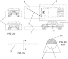
- the mine detection vehicle comprises an attachment at the front which houses at least one antenna (11) connected to at least one sensor (10).
- this attachment at the front only consists of at least one pole (1) attached to the vehicle (2) in such a way that it can be retractable or telescopic, because it only needs to be unleashed in the event of combat, and not, for example, when the vehicle is the base or the barracks.
- the pole (1) forms an angle ( ⁇ ) at 45° with the front of the vehicle (2) given that, in this way, it's possible for the pathway of the roadside and its ditches to be controlled in one sweep.
- ⁇ angle
- other solutions with the pole making other angles with the front of the vehicle could be considered depending on each use or specific application.
- the antenna (11) will be housed inside the pole (1) in such a way that an electrostatic field (3) will be created around the pole (1) and directing the lower direction, using the shield of the upper part of the pole (1) (see illustration 2c, section A-A at the front of the pole). By doing so, the field is exclusively facing the ground, which the area where the anti-tank or anti-personnel mines are buried. In the same way, it can be seen in the illustration how there is also a perimeter antenna (11) which can create a second field (3) which is on the perimeter with regards the vehicle (2) itself.
- a manual device can be seen in illustration 2b for infantry use, which is essentially a pole (1a) made with light materials, for example, plastic or another nonconductive electronic polymer, and that can be equally extended for individual use.
- the individual pole (1a) will be shielded (11a) on all sides bar one, which is the antenna itself (11) (see illustration 2c, section A-A front of the pole), in such a way that the electrostatic field created inside the pole (1a) by the antenna (11) is facing the open space, creating an electrostatic field (3) which can detect the disturbance in its region or area of influence to warn the soldier carrying it of the presence of a disturbance, which could not only be a mine, but also an IED, or even the presence of weapons buried in hideouts or any other type of disturbance that could be characterized by the sensor (10) that the antenna (11) is connected to from the individual pole (1a).
- the vehicle (2) comprises a first antenna (11) that surrounds the vehicle and that creates a first electrostatic field (3) close to the vehicle's own bodywork, in such a way that the closest of threats can be detected and profiled, such as people approaching, or foreign objects attached to it.
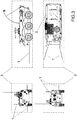
- the vehicle with the system configured for detecting IED will compose, preferably multiple poles (1), the same type of those indicated for detecting mines, but which, given the special threat that IEDs pose, they must also generate an electric field (3) of 360° around the vehicle, even in the upper section, because many of these devices are located in urban areas on windows and ledges or even in areas with trees on branches high above. Therefore, detection of these devices must be done with full coverage of the vehicle (2).
- Each of the antennas (11), preferably one per pole (1) will be connected to at least one sensor (10) placed inside the vehicle (2).
- the poles (1) will also form a 45-degree angle ( ⁇ ) with the front of the vehicle (2) like the one in illustration 2a, so that it can cover the filed with better coverage on the pathway and the roadsides.
- ⁇ 45-degree angle
- the poles (1) of the implementations shown in figures 2a and 3 cannot only have a variable angle ( ⁇ ) (understanding this variable angle, both being in a fixed position at a specific angle and changing, as even the pole (1) can be mobile for sweeps) but also its length must be so to be able to detect at an appropriate security range, which could be, in a favored implementation of 10 meters, but it must never be under the total length of the vehicle (2) and which must preferably be at least double the total length of the vehicle carrying it.
- the same individual pole (1a) can be used to detect other types of threats, such as, detecting the presence of people that are hiding in buildings or in hidden places.
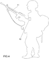
- the antenna (11) can be included in the soldier's individual weapon itself, along with the sensor (10) connected to a control device (100) which will warn the soldier of the threat and even, identify the friend/enemy, which is very important in this type of combat.
- all the sensors (10) are connected to a control device (100) that comprises: one or more processors (101); a memory (102); and one or more programs where the program(s) are stored in the memory (102) and configured to be executed by, at least, the processor(s) (101), including the instruction programs for: (i) profiling a disturbance detected by at least one sensor (10); (ii) focusing at least one camera (12) on the at least one sensor's (10) operational area with a detected disturbance; (iii) monitoring the operational area with a sensor (10) with a detected disturbance; (iv) generating a control signal and (v) notifying a combat management system or BIMS (Battlefield Information Management System).
- BIMS Binary Mobile Broadband Information Management System
- the control device (100) is the same for all implementations and it can be a specific electronic device included in the soldier's infantry combat equipment or even be installed in a combat vehicle's engine itself, or be any other electronic device, if it fulfils the individual features indicated for each implementation.
- the control signal generated by the device (100) can vary.
- the control signal is generally an alarm/warning that can also be associated to a friend/enemy identification signal using the combat management system or directly, with an automatic weapons stations to automatically engage fire, if the combat management system (which obviously includes the force commander on the ground or the soldier himself) identifies the threat as hostile or presumably hostile.
- the IED can be automatically destroyed on detection before it explodes and just after being identified, without giving the enemy any time to react.
Landscapes
- Engineering & Computer Science (AREA)
- Physics & Mathematics (AREA)
- General Engineering & Computer Science (AREA)
- Electromagnetism (AREA)
- Remote Sensing (AREA)
- Life Sciences & Earth Sciences (AREA)
- General Physics & Mathematics (AREA)
- General Life Sciences & Earth Sciences (AREA)
- Geology (AREA)
- Geophysics (AREA)
- Acoustics & Sound (AREA)
- Environmental & Geological Engineering (AREA)
- Robotics (AREA)
- Theoretical Computer Science (AREA)
- Geophysics And Detection Of Objects (AREA)
- Radar Systems Or Details Thereof (AREA)
- Aiming, Guidance, Guns With A Light Source, Armor, Camouflage, And Targets (AREA)
Claims (6)
- System, das einen Waffen- und Sprengstoffdetektor und eine automatische Waffe kombiniert, wobei das System mindestens Folgendes umfasst:eine Kamera; undeinen gesteuerten Magnetfeldsensor (10), der mit mindestens einer Antenne (11) verbunden ist;wobei diese Antenne (11) als einzelne Elektrode konfiguriert ist; undwobei der gesteuerte elektrostatische Feldsensor (10) konfiguriert ist, um eine Störung in dem elektrostatischen Feld (3) zu erfassen, die durch die mindestens eine Antenne (11) erzeugt wird, die mit diesem Sensor (10) verbunden ist;wobei die mindestens eine Antenne (11) an einem Pol (1) angebracht ist; oderam Umfang der Karosserie eines Fahrzeugs (2); oderauf eine einzelne Kampfwaffe; undwobei jeder Magnetfeldsensor (10) mit einer Steuervorrichtung (100) verbunden ist, die umfasst:ein oder mehrere Prozessoren (101);eine Erinnerung (102); undein oder mehrere Programme, in denen die Programme im Speicher (102) gespeichert und so konfiguriert sind, dass sie von mindestens dem Prozessor (den Prozessoren) (101) ausgeführt werden, einschließlich der Befehlsprogramme für:Profilieren einer Störung, die von der mindestens einen Antenne (11) erfasst wird, die mit dem mindestens einen Sensor (10) verbunden ist;Fokussieren der mindestens einen Kamera (12) auf mindestens einen Bereich, in dem die mindestens eine Antenne (11), die mit mindestens einem Sensor (10) verbunden ist, eine Störung erfasst hat;Überwachen mindestens eines Bereichs durch die Kamera (12), in dem die mindestens eine Antenne (11), die mit dem mindestens einen Sensor (10) verbunden ist, eine Störung erfasst hat;Erzeugen eines Steuersignals; undBenachrichtigung eines Kampfmanagementsystems;und das Steuersignal umfasst die folgenden Signale: Aktivieren eines Alarms; Richten der automatischen Waffe auf einen Bereich, in dem mindestens eine Antenne (11), die mit mindestens einem Sensor (10) verbunden ist, eine Störung festgestellt hat; und automatisches Schießen der automatischen Waffe in Richtung eines Bereichs, in dem die mindestens eine Antenne (11), die mit mindestens einem Sensor (10) verbunden ist, eine Störung erkannt hat, wenn sie als feindlich angesehen wird.
- System nach Anspruch 1, wobei sich die mindestens eine Antenne (11) an mindestens einem einziehbaren oder Teleskoppol (1) befindet.
- System nach Anspruch 1 oder 2, bei dem die Stange (1) gemeinsam an einem Fahrzeug (2) befestigt ist.
- Waffen und Sprengstoffverfahren, die in Übereinstimmung mit einem der Ansprüche 1 bis 3 in einem System implementiert sind, das die folgenden Stufen umfasst:Profilieren einer Störung, die von der mindestens einen Antenne (11) erfasst wird, die mit dem mindestens einen Sensor (10) verbunden ist;Fokussieren der mindestens einen Kamera (12) auf mindestens einen Bereich, in dem die mindestens eine Antenne (11), die mit mindestens einem Sensor (10) verbunden ist, eine Störung erfasst hat;Überwachen mindestens eines Bereichs durch die Kamera (12), in dem die mindestens eine Antenne (11), die mit dem mindestens einen Sensor (10) verbunden ist, eine Störung erfasst hat;Erzeugen eines Steuersignals; undBenachrichtigung eines Kampfmanagementsystems;und dadurch gekennzeichnet, dass eine Phase der Identifizierung der Bedrohung als Freund / Feind im Kampfmanagementsystem umfasst.
- Verfahren nach Anspruch 4, umfassend eine Stufe zum Ausdehnen mindestens eines Pols (1) mit mindestens einer Antenne (11) darin.
- Verfahren nach Anspruch 4, das eine Phase umfasst, in der eine Waffe automatisch auf den Bereich gerichtet wird, in dem eine Störung festgestellt wurde, und auf die Waffe geschossen wird, wenn die Störung als feindlich identifiziert wurde.
Priority Applications (1)
| Application Number | Priority Date | Filing Date | Title |
|---|---|---|---|
| PL16861661T PL3372949T3 (pl) | 2015-11-05 | 2016-11-04 | Detektor broni i materiałów wybuchowych oraz sposób detekcji |
Applications Claiming Priority (2)
| Application Number | Priority Date | Filing Date | Title |
|---|---|---|---|
| ES201531589A ES2615202B1 (es) | 2015-11-05 | 2015-11-05 | Detector de armas y explosivos y método de detección |
| PCT/ES2016/070784 WO2017077165A1 (es) | 2015-11-05 | 2016-11-04 | Detector de armas y explosivos y método de detección |
Publications (3)
| Publication Number | Publication Date |
|---|---|
| EP3372949A1 EP3372949A1 (de) | 2018-09-12 |
| EP3372949A4 EP3372949A4 (de) | 2018-10-31 |
| EP3372949B1 true EP3372949B1 (de) | 2020-07-15 |
Family
ID=58662268
Family Applications (1)
| Application Number | Title | Priority Date | Filing Date |
|---|---|---|---|
| EP16861661.3A Active EP3372949B1 (de) | 2015-11-05 | 2016-11-04 | Waffen und explosivstoffdetektor und detektionsverfahren |
Country Status (8)
| Country | Link |
|---|---|
| US (1) | US11086041B2 (de) |
| EP (1) | EP3372949B1 (de) |
| JP (1) | JP6806773B2 (de) |
| CN (1) | CN108369082B (de) |
| ES (2) | ES2615202B1 (de) |
| HK (1) | HK1259472A1 (de) |
| PL (1) | PL3372949T3 (de) |
| WO (1) | WO2017077165A1 (de) |
Families Citing this family (5)
| Publication number | Priority date | Publication date | Assignee | Title |
|---|---|---|---|---|
| EP3553477B1 (de) | 2018-04-13 | 2020-10-14 | Ontech Security, S.L. | Gerät zur messung einer störung in einem kontrollierten magnetfeld |
| US11965716B2 (en) * | 2019-07-22 | 2024-04-23 | JJ1 Holdings Pty Ltd | Landmine, UEO or IED detection and destruction system |
| CN111417280B (zh) * | 2020-05-22 | 2021-02-02 | 东莞市技师学院(东莞市高级技工学校) | 一种电气自动化设备的检测装置 |
| EP4212890A1 (de) | 2022-01-17 | 2023-07-19 | Ontech Security, SL | Verfahren und vorrichtung zur messung von störungen in einem kontrollierten elektromagnetischen feld |
| EP4213121A1 (de) | 2022-01-17 | 2023-07-19 | Ontech Security, SL | Verfahren und vorrichtung zur messung von störungen in einem kontrollierten elektromagnetischen feld |
Family Cites Families (14)
| Publication number | Priority date | Publication date | Assignee | Title |
|---|---|---|---|---|
| US5982180A (en) * | 1997-05-23 | 1999-11-09 | Lockheed Martin Corporation | Metal detection system and process using a high voltage to produce a visible electrical discharge |
| CA2408573C (en) * | 2001-10-17 | 2011-12-20 | Andre Gagnon | Intruder/escapee detection system |
| JP4301080B2 (ja) * | 2004-05-24 | 2009-07-22 | 船井電機株式会社 | 監視システム |
| JP2005351710A (ja) * | 2004-06-09 | 2005-12-22 | Tokyo Gas Co Ltd | 検出対象位置特定装置及び検出対象位置特定方法 |
| US7834320B2 (en) * | 2004-12-06 | 2010-11-16 | Bar-Giora Goldberg | Remote biological, chemical and explosive detector |
| US7512511B1 (en) | 2006-03-30 | 2009-03-31 | The Boeing Company | Improvised explosive device countermeasures |
| FR2944100B1 (fr) | 2009-04-03 | 2016-02-12 | Eca | Dispositif de leurrage notamment pour engin explosif improvise. |
| US20120092019A1 (en) * | 2010-05-05 | 2012-04-19 | Rampart Detection Systems Ltd. | Electric Field Signature Detection Using Exciter-Sensor Arrays |
| FR2972807B1 (fr) * | 2011-03-17 | 2013-12-13 | Mbda France | Systeme integre de lutte contre des engins explosifs improvises |
| US9658155B2 (en) * | 2012-12-17 | 2017-05-23 | Patrick K Brady | System and method for identifying materials using a THz spectral fingerprint in a media with high water content |
| US9494464B2 (en) * | 2013-02-20 | 2016-11-15 | Battelle Energy Alliance, Llc | Terahertz imaging devices and systems, and related methods, for detection of materials |
| ES2534702B1 (es) * | 2013-09-24 | 2016-02-09 | Ontech Security, Sl | Sensor de campos electrostáticos y sistema de seguridad en espacios interiores |
| US9395347B2 (en) | 2013-10-24 | 2016-07-19 | Andrew Lee BOTTRELL | Explosive device detection tool |
| US10001577B2 (en) * | 2014-03-07 | 2018-06-19 | avaSensor, LLC | Matter detector, sensor and locator device and methods of operation |
-
2015
- 2015-11-05 ES ES201531589A patent/ES2615202B1/es not_active Expired - Fee Related
-
2016
- 2016-11-04 HK HK19101878.4A patent/HK1259472A1/zh unknown
- 2016-11-04 CN CN201680072730.XA patent/CN108369082B/zh active Active
- 2016-11-04 WO PCT/ES2016/070784 patent/WO2017077165A1/es not_active Ceased
- 2016-11-04 PL PL16861661T patent/PL3372949T3/pl unknown
- 2016-11-04 ES ES16861661T patent/ES2826828T3/es active Active
- 2016-11-04 US US15/774,245 patent/US11086041B2/en active Active
- 2016-11-04 EP EP16861661.3A patent/EP3372949B1/de active Active
- 2016-11-04 JP JP2018522983A patent/JP6806773B2/ja active Active
Non-Patent Citations (1)
| Title |
|---|
| None * |
Also Published As
| Publication number | Publication date |
|---|---|
| PL3372949T4 (pl) | 2021-03-08 |
| JP6806773B2 (ja) | 2021-01-06 |
| US11086041B2 (en) | 2021-08-10 |
| HK1259472A1 (zh) | 2019-11-29 |
| US20200249371A1 (en) | 2020-08-06 |
| ES2615202B1 (es) | 2018-03-15 |
| WO2017077165A1 (es) | 2017-05-11 |
| EP3372949A1 (de) | 2018-09-12 |
| CN108369082A (zh) | 2018-08-03 |
| JP2018532974A (ja) | 2018-11-08 |
| ES2615202A1 (es) | 2017-06-05 |
| ES2826828T3 (es) | 2021-05-19 |
| EP3372949A4 (de) | 2018-10-31 |
| CN108369082B (zh) | 2020-12-22 |
| PL3372949T3 (pl) | 2021-03-08 |
Similar Documents
| Publication | Publication Date | Title |
|---|---|---|
| EP3372949B1 (de) | Waffen und explosivstoffdetektor und detektionsverfahren | |
| US7512511B1 (en) | Improvised explosive device countermeasures | |
| US20030196543A1 (en) | Mine sweeping and clearing system for land mines | |
| CN106643303A (zh) | 一种基于多模复合传感机理的区域监测与防卫系统 | |
| Habib | Mine detection and sensing technologies-new development potentials in the context of humanitarian demining | |
| US20070131754A1 (en) | Method and system of collecting data using unmanned vehicles having releasable data storage devices | |
| US20110030538A1 (en) | Integrated airport domain awareness response system, system for ground-based transportable defense of airports against manpads, and methods | |
| US20090021417A1 (en) | Method and system for detection of objects | |
| Habib | Humanitarian demining mine detection and sensors | |
| IL228016A (en) | An integrated system for combating improvised explosive devices | |
| Saranya et al. | Ground Penetrating Radar For Identifying Mines In A Minefield | |
| RU235268U1 (ru) | Устройство обнаружения беспилотных летательных аппаратов на базе нелинейного радиолокатора | |
| RU2780146C1 (ru) | Способ дистанционной установки комбинированного средства охранной сигнализации | |
| Gonzalez-Jorge et al. | COUNTER DRONE TECHNOLOGY. | |
| GB2418476A (en) | Defensive land mine | |
| RU2766488C2 (ru) | Устройство дистанционного разминирования | |
| Rowe et al. | Wireless sensor networks for detection of IED emplacement | |
| Carlson et al. | Autonomous mine detection system (AMDS) incorporating SFCW GPR and CWMD sensors for discrimination | |
| Gautami et al. | A homogenous prototype design for IED detection using subsurface ground-penetrating RADAR | |
| RU114546U1 (ru) | Система защиты линейного участка границы | |
| Kumar et al. | Review on smart landmine and landmine detection | |
| Obie | Standardizing Magnetic Surveying for Unexploded Ordnance Detection: Field Implementation in Cambodia | |
| Serhii et al. | ADAPTATION OF TACTICS FOR ENGINEER AND SAPPER UNITS TO THE CONDITIONS OF THE MODERN ASYMMETRIC BATTLEFIELD | |
| Rincón Pabón et al. | System for early warning in hostile areas in the context of the military applications | |
| TR2021005913A2 (tr) | Bi̇r uzaktan algilama si̇stemi̇ |
Legal Events
| Date | Code | Title | Description |
|---|---|---|---|
| STAA | Information on the status of an ep patent application or granted ep patent |
Free format text: STATUS: THE INTERNATIONAL PUBLICATION HAS BEEN MADE |
|
| PUAI | Public reference made under article 153(3) epc to a published international application that has entered the european phase |
Free format text: ORIGINAL CODE: 0009012 |
|
| STAA | Information on the status of an ep patent application or granted ep patent |
Free format text: STATUS: REQUEST FOR EXAMINATION WAS MADE |
|
| 17P | Request for examination filed |
Effective date: 20180604 |
|
| AK | Designated contracting states |
Kind code of ref document: A1 Designated state(s): AL AT BE BG CH CY CZ DE DK EE ES FI FR GB GR HR HU IE IS IT LI LT LU LV MC MK MT NL NO PL PT RO RS SE SI SK SM TR |
|
| AX | Request for extension of the european patent |
Extension state: BA ME |
|
| STAA | Information on the status of an ep patent application or granted ep patent |
Free format text: STATUS: EXAMINATION IS IN PROGRESS |
|
| A4 | Supplementary search report drawn up and despatched |
Effective date: 20181002 |
|
| RIC1 | Information provided on ipc code assigned before grant |
Ipc: F41H 11/12 20110101AFI20180926BHEP Ipc: G01V 3/08 20060101ALI20180926BHEP Ipc: F41H 11/13 20110101ALI20180926BHEP Ipc: F41H 11/136 20110101ALI20180926BHEP Ipc: F41H 11/16 20110101ALI20180926BHEP |
|
| 17Q | First examination report despatched |
Effective date: 20181022 |
|
| DAV | Request for validation of the european patent (deleted) | ||
| DAX | Request for extension of the european patent (deleted) | ||
| GRAP | Despatch of communication of intention to grant a patent |
Free format text: ORIGINAL CODE: EPIDOSNIGR1 |
|
| STAA | Information on the status of an ep patent application or granted ep patent |
Free format text: STATUS: GRANT OF PATENT IS INTENDED |
|
| INTG | Intention to grant announced |
Effective date: 20200218 |
|
| GRAS | Grant fee paid |
Free format text: ORIGINAL CODE: EPIDOSNIGR3 |
|
| GRAA | (expected) grant |
Free format text: ORIGINAL CODE: 0009210 |
|
| STAA | Information on the status of an ep patent application or granted ep patent |
Free format text: STATUS: THE PATENT HAS BEEN GRANTED |
|
| AK | Designated contracting states |
Kind code of ref document: B1 Designated state(s): AL AT BE BG CH CY CZ DE DK EE ES FI FR GB GR HR HU IE IS IT LI LT LU LV MC MK MT NL NO PL PT RO RS SE SI SK SM TR |
|
| REG | Reference to a national code |
Ref country code: CH Ref legal event code: EP Ref country code: GB Ref legal event code: FG4D |
|
| REG | Reference to a national code |
Ref country code: IE Ref legal event code: FG4D |
|
| REG | Reference to a national code |
Ref country code: DE Ref legal event code: R096 Ref document number: 602016040177 Country of ref document: DE |
|
| REG | Reference to a national code |
Ref country code: AT Ref legal event code: REF Ref document number: 1291502 Country of ref document: AT Kind code of ref document: T Effective date: 20200815 |
|
| REG | Reference to a national code |
Ref country code: SE Ref legal event code: TRGR |
|
| REG | Reference to a national code |
Ref country code: LT Ref legal event code: MG4D |
|
| REG | Reference to a national code |
Ref country code: GR Ref legal event code: EP Ref document number: 20200402886 Country of ref document: GR Effective date: 20201116 |
|
| REG | Reference to a national code |
Ref country code: AT Ref legal event code: MK05 Ref document number: 1291502 Country of ref document: AT Kind code of ref document: T Effective date: 20200715 |
|
| REG | Reference to a national code |
Ref country code: NL Ref legal event code: MP Effective date: 20200715 |
|
| PG25 | Lapsed in a contracting state [announced via postgrant information from national office to epo] |
Ref country code: BG Free format text: LAPSE BECAUSE OF FAILURE TO SUBMIT A TRANSLATION OF THE DESCRIPTION OR TO PAY THE FEE WITHIN THE PRESCRIBED TIME-LIMIT Effective date: 20201015 Ref country code: NO Free format text: LAPSE BECAUSE OF FAILURE TO SUBMIT A TRANSLATION OF THE DESCRIPTION OR TO PAY THE FEE WITHIN THE PRESCRIBED TIME-LIMIT Effective date: 20201015 Ref country code: AT Free format text: LAPSE BECAUSE OF FAILURE TO SUBMIT A TRANSLATION OF THE DESCRIPTION OR TO PAY THE FEE WITHIN THE PRESCRIBED TIME-LIMIT Effective date: 20200715 Ref country code: PT Free format text: LAPSE BECAUSE OF FAILURE TO SUBMIT A TRANSLATION OF THE DESCRIPTION OR TO PAY THE FEE WITHIN THE PRESCRIBED TIME-LIMIT Effective date: 20201116 Ref country code: FI Free format text: LAPSE BECAUSE OF FAILURE TO SUBMIT A TRANSLATION OF THE DESCRIPTION OR TO PAY THE FEE WITHIN THE PRESCRIBED TIME-LIMIT Effective date: 20200715 Ref country code: LT Free format text: LAPSE BECAUSE OF FAILURE TO SUBMIT A TRANSLATION OF THE DESCRIPTION OR TO PAY THE FEE WITHIN THE PRESCRIBED TIME-LIMIT Effective date: 20200715 Ref country code: HR Free format text: LAPSE BECAUSE OF FAILURE TO SUBMIT A TRANSLATION OF THE DESCRIPTION OR TO PAY THE FEE WITHIN THE PRESCRIBED TIME-LIMIT Effective date: 20200715 |
|
| PG25 | Lapsed in a contracting state [announced via postgrant information from national office to epo] |
Ref country code: LV Free format text: LAPSE BECAUSE OF FAILURE TO SUBMIT A TRANSLATION OF THE DESCRIPTION OR TO PAY THE FEE WITHIN THE PRESCRIBED TIME-LIMIT Effective date: 20200715 Ref country code: RS Free format text: LAPSE BECAUSE OF FAILURE TO SUBMIT A TRANSLATION OF THE DESCRIPTION OR TO PAY THE FEE WITHIN THE PRESCRIBED TIME-LIMIT Effective date: 20200715 Ref country code: IS Free format text: LAPSE BECAUSE OF FAILURE TO SUBMIT A TRANSLATION OF THE DESCRIPTION OR TO PAY THE FEE WITHIN THE PRESCRIBED TIME-LIMIT Effective date: 20201115 |
|
| PG25 | Lapsed in a contracting state [announced via postgrant information from national office to epo] |
Ref country code: NL Free format text: LAPSE BECAUSE OF FAILURE TO SUBMIT A TRANSLATION OF THE DESCRIPTION OR TO PAY THE FEE WITHIN THE PRESCRIBED TIME-LIMIT Effective date: 20200715 |
|
| REG | Reference to a national code |
Ref country code: DE Ref legal event code: R097 Ref document number: 602016040177 Country of ref document: DE |
|
| PG25 | Lapsed in a contracting state [announced via postgrant information from national office to epo] |
Ref country code: EE Free format text: LAPSE BECAUSE OF FAILURE TO SUBMIT A TRANSLATION OF THE DESCRIPTION OR TO PAY THE FEE WITHIN THE PRESCRIBED TIME-LIMIT Effective date: 20200715 Ref country code: SM Free format text: LAPSE BECAUSE OF FAILURE TO SUBMIT A TRANSLATION OF THE DESCRIPTION OR TO PAY THE FEE WITHIN THE PRESCRIBED TIME-LIMIT Effective date: 20200715 Ref country code: RO Free format text: LAPSE BECAUSE OF FAILURE TO SUBMIT A TRANSLATION OF THE DESCRIPTION OR TO PAY THE FEE WITHIN THE PRESCRIBED TIME-LIMIT Effective date: 20200715 Ref country code: DK Free format text: LAPSE BECAUSE OF FAILURE TO SUBMIT A TRANSLATION OF THE DESCRIPTION OR TO PAY THE FEE WITHIN THE PRESCRIBED TIME-LIMIT Effective date: 20200715 Ref country code: CZ Free format text: LAPSE BECAUSE OF FAILURE TO SUBMIT A TRANSLATION OF THE DESCRIPTION OR TO PAY THE FEE WITHIN THE PRESCRIBED TIME-LIMIT Effective date: 20200715 |
|
| REG | Reference to a national code |
Ref country code: DE Ref legal event code: R082 Ref document number: 602016040177 Country of ref document: DE Representative=s name: TAPPE, UDO, DIPL.-PHYS. DR.RER.NAT., DE |
|
| REG | Reference to a national code |
Ref country code: ES Ref legal event code: FG2A Ref document number: 2826828 Country of ref document: ES Kind code of ref document: T3 Effective date: 20210519 |
|
| PLBE | No opposition filed within time limit |
Free format text: ORIGINAL CODE: 0009261 |
|
| STAA | Information on the status of an ep patent application or granted ep patent |
Free format text: STATUS: NO OPPOSITION FILED WITHIN TIME LIMIT |
|
| PG25 | Lapsed in a contracting state [announced via postgrant information from national office to epo] |
Ref country code: AL Free format text: LAPSE BECAUSE OF FAILURE TO SUBMIT A TRANSLATION OF THE DESCRIPTION OR TO PAY THE FEE WITHIN THE PRESCRIBED TIME-LIMIT Effective date: 20200715 |
|
| 26N | No opposition filed |
Effective date: 20210416 |
|
| PG25 | Lapsed in a contracting state [announced via postgrant information from national office to epo] |
Ref country code: SK Free format text: LAPSE BECAUSE OF FAILURE TO SUBMIT A TRANSLATION OF THE DESCRIPTION OR TO PAY THE FEE WITHIN THE PRESCRIBED TIME-LIMIT Effective date: 20200715 Ref country code: MC Free format text: LAPSE BECAUSE OF FAILURE TO SUBMIT A TRANSLATION OF THE DESCRIPTION OR TO PAY THE FEE WITHIN THE PRESCRIBED TIME-LIMIT Effective date: 20200715 |
|
| REG | Reference to a national code |
Ref country code: CH Ref legal event code: PL |
|
| PG25 | Lapsed in a contracting state [announced via postgrant information from national office to epo] |
Ref country code: LU Free format text: LAPSE BECAUSE OF NON-PAYMENT OF DUE FEES Effective date: 20201104 |
|
| REG | Reference to a national code |
Ref country code: BE Ref legal event code: MM Effective date: 20201130 |
|
| PG25 | Lapsed in a contracting state [announced via postgrant information from national office to epo] |
Ref country code: LI Free format text: LAPSE BECAUSE OF NON-PAYMENT OF DUE FEES Effective date: 20201130 Ref country code: SI Free format text: LAPSE BECAUSE OF FAILURE TO SUBMIT A TRANSLATION OF THE DESCRIPTION OR TO PAY THE FEE WITHIN THE PRESCRIBED TIME-LIMIT Effective date: 20200715 Ref country code: CH Free format text: LAPSE BECAUSE OF NON-PAYMENT OF DUE FEES Effective date: 20201130 |
|
| PG25 | Lapsed in a contracting state [announced via postgrant information from national office to epo] |
Ref country code: IE Free format text: LAPSE BECAUSE OF NON-PAYMENT OF DUE FEES Effective date: 20201104 |
|
| PG25 | Lapsed in a contracting state [announced via postgrant information from national office to epo] |
Ref country code: MT Free format text: LAPSE BECAUSE OF FAILURE TO SUBMIT A TRANSLATION OF THE DESCRIPTION OR TO PAY THE FEE WITHIN THE PRESCRIBED TIME-LIMIT Effective date: 20200715 Ref country code: CY Free format text: LAPSE BECAUSE OF FAILURE TO SUBMIT A TRANSLATION OF THE DESCRIPTION OR TO PAY THE FEE WITHIN THE PRESCRIBED TIME-LIMIT Effective date: 20200715 |
|
| PG25 | Lapsed in a contracting state [announced via postgrant information from national office to epo] |
Ref country code: MK Free format text: LAPSE BECAUSE OF FAILURE TO SUBMIT A TRANSLATION OF THE DESCRIPTION OR TO PAY THE FEE WITHIN THE PRESCRIBED TIME-LIMIT Effective date: 20200715 |
|
| PG25 | Lapsed in a contracting state [announced via postgrant information from national office to epo] |
Ref country code: BE Free format text: LAPSE BECAUSE OF NON-PAYMENT OF DUE FEES Effective date: 20201130 |
|
| PGFP | Annual fee paid to national office [announced via postgrant information from national office to epo] |
Ref country code: TR Payment date: 20230303 Year of fee payment: 7 Ref country code: SE Payment date: 20230227 Year of fee payment: 7 Ref country code: PL Payment date: 20230227 Year of fee payment: 7 Ref country code: IT Payment date: 20230227 Year of fee payment: 7 Ref country code: GR Payment date: 20230227 Year of fee payment: 7 |
|
| REG | Reference to a national code |
Ref country code: SE Ref legal event code: EUG |
|
| PG25 | Lapsed in a contracting state [announced via postgrant information from national office to epo] |
Ref country code: GR Free format text: LAPSE BECAUSE OF NON-PAYMENT OF DUE FEES Effective date: 20240610 |
|
| PG25 | Lapsed in a contracting state [announced via postgrant information from national office to epo] |
Ref country code: GR Free format text: LAPSE BECAUSE OF NON-PAYMENT OF DUE FEES Effective date: 20240610 |
|
| PG25 | Lapsed in a contracting state [announced via postgrant information from national office to epo] |
Ref country code: SE Free format text: LAPSE BECAUSE OF NON-PAYMENT OF DUE FEES Effective date: 20231105 |
|
| PG25 | Lapsed in a contracting state [announced via postgrant information from national office to epo] |
Ref country code: IT Free format text: LAPSE BECAUSE OF NON-PAYMENT OF DUE FEES Effective date: 20231104 |
|
| PG25 | Lapsed in a contracting state [announced via postgrant information from national office to epo] |
Ref country code: IT Free format text: LAPSE BECAUSE OF NON-PAYMENT OF DUE FEES Effective date: 20231104 |
|
| PG25 | Lapsed in a contracting state [announced via postgrant information from national office to epo] |
Ref country code: PL Free format text: LAPSE BECAUSE OF NON-PAYMENT OF DUE FEES Effective date: 20231104 |
|
| REG | Reference to a national code |
Ref country code: ES Ref legal event code: RD2A Effective date: 20250527 |
|
| PGFP | Annual fee paid to national office [announced via postgrant information from national office to epo] |
Ref country code: DE Payment date: 20251107 Year of fee payment: 10 |
|
| PGFP | Annual fee paid to national office [announced via postgrant information from national office to epo] |
Ref country code: GB Payment date: 20251107 Year of fee payment: 10 |
|
| PGFP | Annual fee paid to national office [announced via postgrant information from national office to epo] |
Ref country code: FR Payment date: 20251107 Year of fee payment: 10 |
|
| PGFP | Annual fee paid to national office [announced via postgrant information from national office to epo] |
Ref country code: ES Payment date: 20251211 Year of fee payment: 10 |