EP3372758A1 - Kraftfahrzeugschlüssel - Google Patents
Kraftfahrzeugschlüssel Download PDFInfo
- Publication number
- EP3372758A1 EP3372758A1 EP18154128.5A EP18154128A EP3372758A1 EP 3372758 A1 EP3372758 A1 EP 3372758A1 EP 18154128 A EP18154128 A EP 18154128A EP 3372758 A1 EP3372758 A1 EP 3372758A1
- Authority
- EP
- European Patent Office
- Prior art keywords
- key
- motor vehicle
- bearing
- deformation
- shank
- Prior art date
- Legal status (The legal status is an assumption and is not a legal conclusion. Google has not performed a legal analysis and makes no representation as to the accuracy of the status listed.)
- Granted
Links
Images

Classifications
-
- E—FIXED CONSTRUCTIONS
- E05—LOCKS; KEYS; WINDOW OR DOOR FITTINGS; SAFES
- E05B—LOCKS; ACCESSORIES THEREFOR; HANDCUFFS
- E05B19/00—Keys; Accessories therefor
-
- B—PERFORMING OPERATIONS; TRANSPORTING
- B29—WORKING OF PLASTICS; WORKING OF SUBSTANCES IN A PLASTIC STATE IN GENERAL
- B29C—SHAPING OR JOINING OF PLASTICS; SHAPING OF MATERIAL IN A PLASTIC STATE, NOT OTHERWISE PROVIDED FOR; AFTER-TREATMENT OF THE SHAPED PRODUCTS, e.g. REPAIRING
- B29C65/00—Joining or sealing of preformed parts, e.g. welding of plastics materials; Apparatus therefor
- B29C65/56—Joining or sealing of preformed parts, e.g. welding of plastics materials; Apparatus therefor using mechanical means or mechanical connections, e.g. form-fits
- B29C65/64—Joining a non-plastics element to a plastics element, e.g. by force
- B29C65/645—Joining a non-plastics element to a plastics element, e.g. by force using friction or ultrasonic vibrations
-
- E—FIXED CONSTRUCTIONS
- E05—LOCKS; KEYS; WINDOW OR DOOR FITTINGS; SAFES
- E05B—LOCKS; ACCESSORIES THEREFOR; HANDCUFFS
- E05B19/00—Keys; Accessories therefor
- E05B19/0082—Keys or shanks being removably stored in a larger object, e.g. a remote control or a key fob
-
- E—FIXED CONSTRUCTIONS
- E05—LOCKS; KEYS; WINDOW OR DOOR FITTINGS; SAFES
- E05B—LOCKS; ACCESSORIES THEREFOR; HANDCUFFS
- E05B19/00—Keys; Accessories therefor
- E05B19/04—Construction of the bow or head of the key; Attaching the bow to the shank
-
- E—FIXED CONSTRUCTIONS
- E05—LOCKS; KEYS; WINDOW OR DOOR FITTINGS; SAFES
- E05B—LOCKS; ACCESSORIES THEREFOR; HANDCUFFS
- E05B19/00—Keys; Accessories therefor
- E05B19/26—Use of special materials for keys
Definitions
- the invention relates to a motor vehicle key, in particular for a motor vehicle radio key, comprising a key shank and a bearing element, wherein the key shank is arranged within the bearing element and between the bearing element and the key shank a deformation element, in particular a plastic element, is arranged, which is subsequently formed deformable.
- the invention also relates to a method according to independent claim 16.
- a motor vehicle key for a motor vehicle radio key is known from the prior art.
- the motor vehicle key has a key shank and a bearing element designed as a cap element.
- the key shank is pinned to the bearing member by means of a pin so that the key shank is firmly connected to the bearing member.
- tolerance deviations, especially in the bearing element, the pin and the key shank unavoidable. This can lead to increased rejection of these components.
- the bearing element has at least one bearing recess
- the key shank has at least one key shank recess, wherein after the deformation of the deformation element, the deformed deformation element at least partially within the bearing recess and at least is partially disposed within the réelleschaftausEnglishung and the key shaft and the bearing element non-positively and / or positively connects. Due to this advantageous measure, the manufacturing process of the motor vehicle key is simplified because compared to the prior art, the tolerance influence of the components is minimized to each other, so that consequently the manufacturing cost of the motor vehicle key can be reduced.
- the deformation element may be formed as a plastic element. But other deformable materials are possible.
- the melting temperature of the Deformation element is lower than the melting temperature of the material of the key shaft and the bearing element.
- the deformed material of the deformation element in particular the deformed plastic of the plastic element, penetrates into the bearing recess and the key shank recess and connects the key shank firmly and securely to the bearing element.
- the key shank recess and the bearing recess are so firmly and securely connected to one another by the deformed deformation element, in particular plastic element, so that a lock cylinder assigned to the motor vehicle can be reliably actuated with the key shank without difficulty.
- the bearing element has a trough for the arrangement of the deformation element.
- the trough ensures that upon a change in the state of aggregation of the material to be deformed, in particular of the plastic, this also remains in the bearing element, in particular in the trough and is thus available to flow into the bearing recess and the key shank recess. With the help of the tub is thus ensured that the key shank can be firmly and securely connected to the bearing element.
- the solid and secure connection between the key shank and the bearing element can be further improved if the bearing element has a first bearing recess and a second bearing recess, which are arranged within the tub, preferably opposite and / or side by side, to each other. It may even make sense, depending on the requirements of the motor vehicle key, to increase the number of bearing recesses to up to six bearing recesses and to increase the number of key shafts to as many as four key shafts.
- the construction of the motor vehicle key can be formed when the deformation element is formed in cross section as a U-profile, wherein the U-profile comprises a first leg and a second leg, which have a distance a1 to each other.
- the U-profile has the advantage that the key shank, in particular a connecting end of the key shank, to Processing of the deformation element can be safely and securely recorded therein. It may then offer, if the deformation element is designed as a container.
- the container is formed substantially pot-shaped and has an enclosed side wall. When the deformation element is processed, the enclosed side wall is substantially evenly distributed in the bearing element, in particular in the trough of the bearing element. As a result, the bearing recess and the key shaft recess can be reliably filled with the deformed material, in particular with the deformed plastic.
- the mounting of the deformation element in the bearing element can be simplified if the deformation element is designed as an insert.
- a machine or a worker on the assembly line engages the deformation element and places it in the bearing element, in particular in the trough of the bearing element.
- the deformation element in its undeformed state has a total width a2 and the bearing element, in particular the trough, a width b1, wherein the width b1 of the bearing element is less than / equal to the total width a2 of the undeformed deformation element. This ensures that the deformation element can be safely and easily mounted in the bearing element. If the width b1 of the bearing element is equal to the total width a2 of the deformation element, then the deformation element must be pressed into the bearing element.
- the key shank in particular at a connecting end, has a width c1, wherein the width c1 of the key shank is greater than the width a1 of the spaced apart one another Leg of the U-profile of the deformation element is formed.
- the sonotrode preferably with the key shank, in particular with one end of the key shaft, can be coupled.
- the key shaft is excited by the sonotrode to a vibration.
- the sonotrode is coupled to the key shaft.
- frictional forces are generated by which heat is generated on the plastic element. This heat causes the plastic to begin to deform.
- the deformed plastic then flows into the bearing recess and the key shaft recess. Subsequently, the sonotrode can be removed from the key shank and the plastic hardens, so that the key shank is firmly connected to the bearing element.
- connection between the bearing element and the key shank can be made even more reliable if the bearing recess is U-shaped.
- the U-shaped bearing recesses can absorb the deformed material, in particular the deformed plastic, well, without causing air pockets within the bearing recess. This increases the stability of the connection between the key shank and the bearing element.
- the key shank is made of metal, preferably of steel or nickel silver.
- the fixed connection between the key shank and the bearing element can be ensured if the plastic element is made of polyamide. Damage to the bearing element during the deformation of the plastic element can be ensured if the bearing element made of metal, preferably made of die-cast, is formed.
- the motor vehicle key is designed as an emergency key and is designed for arrangement in the motor vehicle radio key.
- the bearing element as Cap element and / or be designed as an actuator for the vehicle radio key.
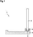
- FIG. 1 is a motor vehicle key 1 shown for a motor vehicle radio key, not shown.
- the motor vehicle key 1 can serve as an emergency key for the vehicle radio key, if the Car key, for example, is inoperable due to lack of energy.
- the motor vehicle key 1 can be arranged on or in the motor vehicle radio key.
- the motor vehicle key 1 comprises a key shank 2 formed from metal, in particular from steel or nickel silver, which is designed to operate a motor vehicle locking cylinder.
- the key shank 2 includes a connection end 3 having a width c1.
- the key shank 2 is arranged within a bearing element 4.
- the bearing element 4 is made of metal, in particular die-cast, wherein in the present case this is additionally configured as a cap element and / or actuating element.
- the bearing element 4 can then cover, for example, an opening of a housing of the motor vehicle radio key.
- a user when operating the motor vehicle lock cylinder use the bearing element 4 to operate with the help of the key shank 2, the lock cylinder. In this case, the user attacks, for example with his thumb and forefinger, the bearing element 4, so that this is then used as an actuator.
- the bearing element 4 has a trough 5 with a width b1, which is provided for the arrangement of a deformation element 6.
- the deformation element 6 is preferably formed from a plastic element 6, which is subsequently deformable.
- the plastic element 6 comprises in the present embodiment, the material polyamide. Further, the plastic element 6 may be configured as Einlegteil and may be in the bearing element 4, in particular in the tub 5, are inserted. Pushing the plastic element 6 into the bearing element 4 is likewise conceivable.
- the plastic element 6 is designed as a container 7, which preferably comprises a circumferential wall 8.
- the plastic element 6 is visualized in its undeformed state, wherein the plastic element 6 is formed in cross section as a U-profile 9, wherein the U-profile 9 comprises a first leg 10 and a second leg 11, which have a distance a1 to each other.
- the plastic element 6 has a total width a2 in its undeformed state.
- the bearing element 3 is provided with a first, preferably U-shaped, bearing recess 12 and with a second, preferably U-shaped, formed bearing recess 13, which within the Trough 4 are arranged opposite to each other.
- the shows FIG. 2 in that four key shank recesses 14, 15, 16, 17 are provided on the key shank.
- the width b1 of the bearing member 4 is smaller than or equal to the total width b2 of the undeformed plastic member 6 and the width c1 of the key shank 2, in particular, the connecting end 3 of the key shank 2 is greater than the width a1 of each other
- the method sequence for producing the motor vehicle key 1 is disclosed below, in particular for connecting the key shaft 2 to the bearing element 4.
- the plastic element 6 is inserted or pressed into the bearing element 4, in particular in the tub 5. If the total width a2 of the undeformed plastic element 6 is equal to the width b1 of the bearing element 4, the plastic element 6 must be pressed into the trough 5. In this case, there is a press fit between the plastic element 6 and the bearing element 4, in particular the trough 4. If the total width a2 of the undeformed plastic element 6 is smaller than the width b1 of the bearing element 4, then the plastic element 6 without resistance in the Tray 4 are inserted. However, the interference fit between the plastic element 6 and the bearing element 4 offers the advantage that in the further deformation of the plastic element 6, this can remain immovably in the trough 5.
- the key shank 2 is coupled to the sonotrode.
- the sonotrode can touch the key shaft 2 or be attached to this.
- the oscillation of the key shank 2 is transmitted to the plastic element 6. This happens very early, because the width c1 of the connecting end 3 of the key shank 2 is greater than that Distance a1 of the legs 10, 11. In this case, friction between the key shank 2 and the plastic element 6 is generated. The friction generates heat that deforms the plastic element 6.
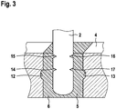
- the deformed plastic of the plastic element 6 flows into the key shaft recesses 14, 15, 16, 17 and into the bearing recesses 13, 14, so that a positive and / or positive connection is established between the key shaft 2 and the bearing element 4 will, as in the FIG. 3 is visualized.
- the key shank 2 is securely and reliably connected to the bearing element 4.
- bearing recesses in the bearing element in particular in the tub 4
- These bearing recesses can also be arranged next to each other and / or opposite each other.
- the deformation element can also be formed from other deformable materials, such as lead. It only has to be ensured that the melting temperature of the deformation element is lower than the melting temperature of the material of the key shaft and of the bearing element.
Landscapes
- Engineering & Computer Science (AREA)
- Mechanical Engineering (AREA)
- Lock And Its Accessories (AREA)
Abstract
Description
- Die Erfindung betrifft einen Kraftfahrzeugschlüssel, insbesondere für einen Kraftfahrzeugfunkschlüssel, aufweisend einen Schlüsselschaft und ein Lagerelement, wobei der Schlüsselschaft innerhalb des Lagerelements angeordnet ist und zwischen dem Lagerelement und dem Schlüsselschaft ein Verformungselement, insbesondere ein Kunststoffelement, angeordnet ist, welches nachträglich verformbar ausgebildet ist. Die Erfindung betrifft ebenfalls ein Verfahren gemäß dem unabhängigen Patentanspruch 16.
- Aus dem Stand der Technik ist ein Kraftfahrzeugschlüssel für einen Kraftfahrzeugfunkschlüssel bekannt. Der Kraftfahrzeugschlüssel weist einen Schlüsselschaft und ein als Kappenelement ausgebildetes Lagerelement auf. Der Schlüsselschaft wird mit dem Lagerelement mittels eines Stifts verstiftet, so dass der Schlüsselschaft mit dem Lagerelement fest verbunden ist. Dabei sind Toleranzabweichungen, insbesondere bei dem Lagerelement, dem Stift und dem Schlüsselschaft unvermeidbar. Dies kann zu einem erhöhten Ausschuss dieser Bauteile führen.
- Es ist daher die Aufgabe der Erfindung, die Herstellungskosten für einen Kraftfahrzeugschlüssel zu verringern.
- Die Aufgabe wird gelöst durch den kennzeichnenden Teil des Patentanspruchs 1. Es ist dabei vorgesehen, dass das Lagerelement mindestens eine Lagerausnehmung aufweist, und der Schlüsselschaft mindestens eine Schlüsselschaftausnehmung aufweist, wobei nach der Verformung des Verformungselements, das verformte Verformungselement zumindest teilweise innerhalb der Lagerausnehmung und zumindest teilweise innerhalb der Schlüsselschaftausnehmung angeordnet ist und den Schlüsselschaft und das Lagerelement kraft- und/oder formschlüssig verbindet. Aufgrund dieser vorteilhaften Maßnahme wird der Herstellungsprozess des Kraftfahrzeugschlüssels vereinfacht, weil im Vergleich zum Stand der Technik der Toleranzeinfluss der Bauteile zueinander minimiert wird, so dass folglich die Herstellungskosten für den Kraftfahrzeugschlüssel gesenkt werden können. Das Verformungselement kann als Kunststoffelement ausgebildet sein. Aber auch andere verformbare Materialien sind möglich. Es muss lediglich sichergestellt werden, dass die Schmelztemperatur des Verformungselements niedriger ist, als die Schmelztemperatur des Materials des Schlüsselschafts und des Lagerelements. Für die vorliegende Erfindung kann es sich anbieten das Verformungselement aus Kunststoff auszubilden. Das verformte Material des Verformungselements, insbesondere der verformte Kunststoff des Kunststoffelements, dringt in die Lagerausnehmung und die Schlüsselschaftausnehmung ein und verbindet den Schlüsselschaft fest und sicher mit dem Lagerelement. Die Schlüsselschaftausnehmung und die Lagerausnehmung werden durch das verformte Verformungselement, insbesondere Kunststoffelement, so fest und sicher miteinander verbunden, so dass mit dem Schlüsselschaft problemlos ein dem Kraftfahrzeug zugeordneter Schließzylinder zuverlässig betätigt werden kann.
- Um sicherzustellen, dass der verformte Kunststoff auch in die Lagerausnehmung und die Schlüsselschaftausnehmung eindringt, kann vorgesehen sein, dass das Lagerelement eine Wanne zur Anordnung des Verformungselements aufweist. Die Wanne sorgt dafür, dass bei einer Änderung des Aggregatzustands des zu verformenden Materials, insbesondere des Kunststoffs, auch dieses in dem Lagerelement, insbesondere in der Wanne verbleibt und somit zur Verfügung steht, um in die Lagerausnehmung und die Schlüsselschaftausnehmung zu strömen. Mit Hilfe der Wanne wird somit sichergestellt, dass der Schlüsselschaft fest und sicher mit dem Lagerelement verbunden werden kann.
- Die feste und sichere Verbindung zwischen dem Schlüsselschaft und dem Lagerelement kann weiter verbessert werden, wenn das Lagerelement eine erste Lagerausnehmung und eine zweite Lagerausnehmung aufweist, welche innerhalb der Wanne, vorzugsweise gegenüberliegend und/oder nebeneinander, zueinander angeordnet sind. Es kann sogar in Abhängigkeit von den Anforderungen des Kraftfahrzeugschlüssels Sinn machen, die Anzahl der Lagerausnehmung auf bis zu sechs Lagerausnehmungen zu erhöhen, und die Anzahl der Schlüsselschaftausnehmungen auf bis zu vier Schlüsselschaftausnehmungen zu erhöhen.
- Sehr einfach kann die Konstruktion des Kraftfahrzeugschlüssels ausgebildet werden, wenn das Verformungselement im Querschnitt als U-Profil ausgebildet ist, wobei das U-Profil einen ersten Schenkel und einen zweiten Schenkel umfasst, die einen Abstand a1 zueinander aufweisen. Das U-Profil weist den Vorteil auf, dass der Schlüsselschaft, insbesondere ein Verbindungsende des Schlüsselschafts, zur Verarbeitung des Verformungselements darin sicher und fest aufgenommen werden kann. Dabei kann es sich dann anbieten, wenn das Verformungselement als Behälter ausgebildet ist. Der Behälter ist im Wesentlichen topfförmig ausgebildet und weist eine umschlossene Seitenwand auf. Wenn das Verformungselement verarbeitet wird, wird die umschlossene Seitenwand im Wesentlichen gleichmäßig in dem Lagerelement, insbesondere in der Wanne des Lagerelements verteilt. Dies führt dazu, dass die Lagerausnehmung und die Schlüsselschaftausnehmung zuverlässig mit dem verformten Material, insbesondere mit dem verformten Kunststoff, befüllbar sind.
- Die Montage des Verformungselements in das Lagerelement kann vereinfacht werden, wenn das Verformungselement als Einlegeteil ausgebildet ist. Eine Maschine oder ein Werker an der Montagelinie greift das Verformungselement und legt dieses in das Lagerelement, insbesondere in die Wanne des Lagerelements ein. Dabei sollte beachtet werden, dass das Verformungselement in seinem unverformten Zustand eine Gesamtbreite a2 aufweist und das Lagerelement, insbesondere die Wanne, eine Breite b1 aufweist, wobei die Breite b1 des Lagerelements kleiner/gleich als die Gesamtbreite a2 des unverformten Verformungselements ausgebildet ist. Damit wird sichergestellt, dass sich das Verformungselement sicher und einfach in das Lagerelement montieren lässt. Wenn die Breite b1 des Lagerelements gleich der Gesamtbreite a2 des Verformungselements ist, dann muss das Verformungselement in das Lagerelement hineingedrückt werden. In diesem Fall handelt es sich zwischen dem Lagerelement und dem Verformungselement um eine Presspassung, die dafür sorgt, dass das Verformungselement sicher und fest innerhalb des Lagerelements, insbesondere in der Wanne, angeordnet ist. Dies ist besonders vorteilhaft bei der weiteren Verarbeitung des Verformungselements, weil der Schlüsselschaft präzise mit dem Verformungselement koppelbar ist bzw. form- und/oder kraftschlüssig verbunden werden kann.
- Um bereits frühzeitig bei der Herstellung des Kraftfahrzeugschlüssels einen Kontakt zwischen dem Schlüsselschaft und dem Verformungselement herzustellen, kann vorgesehen sein, dass der Schlüsselschaft, insbesondere an einem Verbindungsende, eine Breite c1 aufweist, wobei die Breite c1 des Schlüsselschafts größer als die Breite a1 der zueinander beabstandeten Schenkel des U-Profils des Verformungselements ausgebildet ist. Somit wird frühzeitig bei der Verarbeitung des Verformungselements, insbesondere um den Aggregatzustand des Verformungselements von Beginn an zu verändern, gesorgt, dass das zu verformende Material, insbesondere der Kunststoff, in die Lagerausnehmung und die Schlüsselschaftausnehmung gelangt.
- Eine zuverlässige Verformung des Kunststoffelements kann sichergestellt werden, wenn die Verformung des Kunststoffelements mittels einer Sonotrode zur Erzeugung von Ultraschallwellen durchführbar ist, wobei die Sonotrode vorzugsweise mit dem Schlüsselschaft, insbesondere mit einem Ende des Schlüsselschafts, koppelbar ist. Der Schlüsselschaft wird durch die Sonotrode zu einer Schwingung angeregt. Dazu wird die Sonotrode mit dem Schlüsselschaft gekoppelt. Wenn das Verbindungsende mit dem Kunststoffelement in Kontakt kommt, entstehen Reibungskräfte, durch die Wärme am Kunststoffelement erzeugt wird. Diese Wärme sorgt dafür, dass der Kunststoff beginnt, sich zu verformen. Der verformte Kunststoff strömt danach in die Lagerausnehmung und die Schlüsselschaftausnehmung. Anschließend kann die Sonotrode vom Schlüsselschaft entfernt werden und der Kunststoff härtet aus, so dass der Schlüsselschaft fest mit dem Lagerelement verbunden ist.
- Die Verbindung zwischen dem Lagerelement und dem Schlüsselschaft kann noch zuverlässiger ausgebildet werden, wenn die Lagerausnehmung U-förmig ausgebildet ist. Die U-förmig ausgebildeten Lagerausnehmungen können das verformte Material, insbesondere den verformten Kunststoff, gut aufnehmen, ohne dass Lufteinschlüsse innerhalb der Lagerausnehmung entstehen. Dies erhöht die Stabilität der Verbindung zwischen dem Schlüsselschaft und dem Lagerelement.
- Um das Verformungselement, insbesondere das Kunststoffelement, gut verformen zu können, kann vorgesehen sein, dass der Schlüsselschaft aus Metall, vorzugsweise aus Stahl oder Neusilber, ausgebildet ist. Die feste Verbindung zwischen dem Schlüsselschaft und dem Lagerelement kann sichergestellt werden, wenn das Kunststoffelement aus Polyamid ausgebildet ist. Eine Beschädigung des Lagerelements während des Verformens des Kunststoffelements kann gewährleistet werden, wenn das Lagerelement aus Metall, vorzugsweise aus Druckguss, ausgebildet ist.
- Um den Komfort für den Benutzer zu erhöhen, kann gemäß einer bevorzugten Ausführung des Kraftfahrzeugschlüssels vorgesehen sein, dass der Kraftfahrzeugschlüssel als Notschlüssel ausgebildet ist und zur Anordnung in dem Kraftfahrzeugfunkschlüssel ausgebildet ist. Dabei kann das Lagerelement als Kappenelement und/oder als Betätigungselement für den Kraftfahrzeugfunkschlüssel ausgebildet sein.
- Des Weiteren wird die Aufgabe gelöst durch das Verfahren gemäß Patentanspruch 16.
- Das erfindungsgemäße Verfahren zum Herstellen eines Kraftfahrzeugschlüssels ist gekennzeichnet durch die folgenden Verfahrensschritte:
- a) Einlegen eines, insbesondere im Querschnitt U-förmig ausgebildeten, Verformungselements, insbesondere eines Kunststoffelements, in ein Lagerelement aufweisend mindestens eine Lagerausnehmung,
- b) Koppeln einer Sonotrode zur Erzeugung von Ultraschallwellen mit einem Schlüsselschaft aufweisend mindestens eine Schlüsselschaftausnehmung,
- c) Hineinführen des Schlüsselschafts in das Verformungselement,
- d) Schwingungsanregung des Schlüsselschafts durch die Sonotrode,
- e) Verformen des Verformungselements durch den schwingenden Schlüsselschaft in die Schlüsselschaftausnehmung und in die Lagerausnehmung zur Herstellung einer kraft- und/oder formschlüssigen Verbindung zwischen dem Lagerelement und dem Schlüsselschaft,
- f) Abkühlen und Verfestigen des verformten Verformungselements zur Herstellung einer kraft- und/oder formschlüssigen Verbindung zwischen dem Lagerelement und dem Schlüsselschaft.
- Der erfindungsgemäße Kraftfahrzeugschlüssel wird anhand eines Ausführungsbeispiels näher beschrieben. Die Figuren zeigen:
- Figur 1
- einen erfindungsgemäßen Kraftfahrzeugschlüssel, bei welchem ein Schlüsselschaft mit einem Lagerelement verbunden ist,
- Figur 2
- einen Ausschnitt A des Kraftfahrzeugschlüssels vor dem Verbinden des Schlüsselschafts mit dem Lagerelement, und
- Figur 3
- den Ausschnitt A des Kraftfahrzeugschlüssels nach dem Verbinden des Schlüsselschafts mit dem Lagerelement.
- In der
Figur 1 ist ein Kraftfahrzeugschlüssel 1 für einen nicht näher dargestellten Kraftfahrzeugfunkschlüssel gezeigt. Der Kraftfahrzeugschlüssel 1 kann als Notschlüssel für den Kraftfahrzeugfunkschlüssel dienen, wenn der Kraftfahrzeugfunkschlüssel beispielsweise aufgrund fehlender Energie unbedienbar ist. Dabei kann der Kraftfahrzeugschlüssel 1 am oder im Kraftfahrzeugfunkschlüssel angeordnet werden. - Der Kraftfahrzeugschlüssel 1 umfasst einen aus Metall, insbesondere aus Stahl oder Neusilber, ausgebildeten Schlüsselschaft 2, der zum Bedienen eines Kraftfahrzeugschließzylinders ausgebildet ist. Der Schlüsselschaft 2 umfasst ein Verbindungsende 3, welches eine Breite c1 aufweist. Der Schlüsselschaft 2 ist innerhalb eines Lagerelements 4 angeordnet. Das Lagerelement 4 ist aus Metall, insbesondere aus Druckguss, ausgebildet, wobei im vorliegenden Fall dieses zusätzlich noch als Kappenelement und/oder Betätigungselement ausgestaltet ist. Das Lagerelement 4 kann dann beispielsweise eine Öffnung eines Gehäuses des Kraftfahrzeugfunkschlüssels abdecken. Zusätzlich kann ein Benutzer beim Bedienen des Kraftfahrzeugschließzylinders das Lagerelement 4 benutzen, um mit Hilfe des Schlüsselschaftes 2 den Schließzylinder zu bedienen. Dabei greift der Benutzer beispielsweise mit seinem Daumen und seinem Zeigefinger das Lagerelement 4 an, so dass dieses dann als Betätigungselement verwendbar ist.
- Das Lagerelement 4 weist eine Wanne 5 mit einer Breite b1 auf, welche zur Anordnung eines Verformungselements 6 vorgesehen ist. Dabei ist das Verformungselement 6 vorzugsweise aus einem Kunststoffelement 6 ausgebildet, welches nachträglich verformbar ist. Das Kunststoffelement 6 umfasst im vorliegenden Ausführungsbeispiel den Werkstoff Polyamid. Ferner kann das Kunststoffelement 6 als Einlegteil ausgestaltet sein und kann in das Lagerelement 4, insbesondere in die Wanne 5, eingelegt werden. Ein Hineindrücken des Kunststoffelements 6 in das Lagerelement 4 ist ebenfalls denkbar.
- Des Weiteren ist das Kunststoffelement 6 als Behälter 7 ausgebildet, welcher vorzugsweise eine umlaufende Wandung 8 umfasst. In der
Figur 2 ist das Kunststoffelement 6 in seinem unverformten Zustand visualisiert, wobei das Kunststoffelement 6 im Querschnitt als U-Profil 9 ausgebildet ist, wobei das U-Profil 9 einen ersten Schenkel 10 und einen zweiten Schenkel 11 umfasst, die einen Abstand a1 zueinander aufweisen. Des Weiteren erkennt man in derFigur 2 , dass das Kunststoffelement 6 in seinem unverformten Zustand eine Gesamtbreite a2 aufweist. DieFigur 2 offenbart weiter, dass das Lagerelement 3 mit einer ersten, vorzugsweise U-förmig ausgebildeten, Lagerausnehmung 12 und mit einer zweiten, vorzugsweise U-förmig, ausgebildeten Lagerausnehmung 13 versehen ist, welche innerhalb der Wanne 4 gegenüberliegend zueinander angeordnet sind. Des Weiteren zeigt dieFigur 2 , dass am Schlüsselschaft vier Schlüsselschaftausnehmung 14, 15, 16, 17 vorgesehen sind. - Im Ergebnis ist im unverformten Zustand des Kunststoffelements 6 die Breite b1 des Lagerelements 4 kleiner/gleich als die Gesamtbreite b2 des unverformten Kunststoffelements 6 und die Breite c1 des Schlüsselschaftes 2, insbesondere des Verbindungsendes 3 des Schlüsselschafts 2, ist größer als die Breite a1 der zueinander beabstandeten Schenkel 10, 11 des U-Profils des Kunststoffelements 6. Nach der Verformung des Kunststoffelements 6 mittels einer nicht näher dargestellten Sonotrode zur Erzeugung von Ultraschallwellen, welche mit dem Schlüsselschaft 2, insbesondere mit einem nicht gezeigten Ende des Schlüsselschafts 2 koppelbar ist, ist das verformte Kunststoffelement 6 in den Lagerausnehmung 13,14 und in den Schlüsselschaftausnehmungen 14, 15, 16, 17 angeordnet, wie dies in der
Figur 3 gezeigt ist. Im Endergebnis sind der Schlüsselschaft 2 und das Lagerelement 4 kraft- und/oder formschlüssig miteinander verbunden. - Im Folgenden wird der Verfahrensablauf zur Herstellung des Kraftfahrzeugschlüssels 1 offenbart, insbesondere zur Verbindung des Schlüsselschafts 2 mit dem Lagerelement 4.
- Dabei wird zunächst das Kunststoffelement 6 in das Lagerelement 4, insbesondere in die Wanne 5 eingelegt oder hineingedrückt. Wenn die Gesamtbreite a2 des unverformten Kunststoffelements 6 gleich der Breite b1 des Lagerelements 4 ist, muss das Kunststoffelement 6 in die Wanne 5 hineingedrückt werden. In diesem Fall handelt es sich um eine Presspassung zwischen dem Kunststoffelement 6 und dem Lagerelement 4, insbesondere der Wanne 4. Falls die die Gesamtbreite a2 des unverformten Kunststoffelements 6 kleiner der Breite b1 des Lagerelements 4 ist, dann kann das Kunststoffelement 6 ohne Widerstand in die Wanne 4 hineingelegt werden. Die Presspassung zwischen dem Kunststoffelement 6 und dem Lagerelement 4 bietet allerdings den Vorteil, dass bei der weiteren Verformung des Kunststoffelements 6 dieses unbeweglich in der Wanne 5 verbleiben kann. Vor dem Anordnen des Kunststoffelements 6 in die Wanne 5 oder aber auch danach wird der Schlüsselschaft 2 mit der Sonotrode gekoppelt. Dabei kann die Sonotrode den Schlüsselschaft 2 berühren oder an diesem befestigt werden. Wie bereits oben beschrieben, kann man mit der Sonotrode Ultraschallwellen erzeugen, welche den Schlüsselschaft 2 in Schwingung versetzen. Wenn der Schlüsselschaft 2 in das Kunststoffelement 6, insbesondere in den Behälter 7, hineingeführt wird, überträgt sich die Schwingung des Schlüsselschafts 2 auf das Kunststoffelement 6. Dies passiert sehr frühzeitig, weil die Breite c1 des Verbindungsendes 3 des Schlüsselschafts 2 größer ist, als der Abstand a1 der Schenkel 10, 11. Dabei wird Reibung zwischen dem Schlüsselschaft 2 und dem Kunststoffelement 6 erzeugt. Durch die Reibung wird Wärme erzeugt, die das Kunststoffelement 6 verformt. Bei der Verformung des Kunststoffelements strömt der verformte Kunststoff des Kunststoffelements 6 in die Schlüsselschaftausnehmungen 14, 15, 16, 17 und in die Lagerausnehmungen 13, 14, so dass ein eine kraft- und/oder formschlüssige Verbindung zwischen dem Schlüsselschaft 2 und dem Lagerelement 4 hergestellt wird, wie dies in der
Figur 3 visualisiert ist. Nach dem Abkühlen und Verfestigen des verformten Kunststoffelements 6 ist der Schlüsselschaft 2 sicher und zuverlässig mit dem Lagerelement 4 verbunden. - Andere Ausgestaltungen des Kraftfahrzeugschlüssel 1 sind möglich, so dass auch bis zu sechs Lagerausnehmungen in dem Lagerelement, insbesondere in der Wanne 4, angeordnet sein können. Diese Lagerausnehmungen können auch nebeneinander und/oder gegenüberliegend zueinander angeordnet sein.
- Das Verformungselement kann auch aus anderen verformbaren Materialien ausgebildet sein, wie beispielsweise Blei. Es muss lediglich sichergestellt werden, dass die Schmelztemperatur des Verformungselements niedriger ist, als die Schmelztemperatur des Materials des Schlüsselschafts und des Lagerelements.
-
- 1
- Kraftfahrzeugschlüssel
- 2
- Schlüsselschaft
- 3
- Verbindungsende
- 4
- Lagerelement
- 5
- Wanne
- 6
- Verformungselement; Kunststoffelement
- 7
- Behälter
- 8
- Wandung
- 9
- U-Profil
- 10
- erster Schenkel des U-Profils
- 11
- zweiter Schenkel des U-Profils
- 12
- erste Lagerausnehmung
- 13
- zweite Lagerausnehmung
- 14
- erste Schlüsselschaftausnehmung
- 15
- zweite Schlüsselschaftausnehmung
- 16
- dritte Schlüsselschaftausnehmung
- 17
- vierte Schlüsselschaftausnehmung
Claims (17)
- Kraftfahrzeugschlüssel (1), insbesondere für einen Kraftfahrzeugfunkschlüssel, aufweisend einen Schlüsselschaft (2) und ein Lagerelement (4), wobei der Schlüsselschaft (2) innerhalb des Lagerelements (2) angeordnet ist und zwischen dem Lagerelement (4) und dem Schlüsselschaft (2) ein Verformungselement (6), insbesondere ein Kunststoffelement (6), angeordnet ist, welches nachträglich verformbar ausgebildet ist,
dadurch gekennzeichnet, dass
das Lagerelement (4) mindestens eine Lagerausnehmung (12, 13) aufweist, und der Schlüsselschaft (2) mindestens eine Schlüsselschaftausnehmung (14, 15, 16, 17) aufweist, wobei nach der Verformung des Verformungselements, das verformte Verformungselement (6) zumindest teilweise innerhalb der Lagerausnehmung (12, 13) und zumindest teilweise innerhalb der Schlüsselschaftausnehmung (14, 15, 16, 17) angeordnet ist und den Schlüsselschaft (2) und das Lagerelement (4) kraft- und/oder formschlüssig verbindet. - Kraftfahrzeugschlüssel (1) nach Anspruch 1, dadurch gekennzeichnet, dass das Lagerelement (4) eine Wanne (5) zur Anordnung des Verformungselement (6) aufweist.
- Kraftfahrzeugschlüssel (1) nach Anspruch 2, dadurch gekennzeichnet, dass das Lagerelement (4) eine erste Lagerausnehmung (12) und eine zweite Lagerausnehmung (13) aufweist, welche innerhalb der Wanne (5), vorzugsweise gegenüberliegend und/oder nebeneinander, zueinander angeordnet sind.
- Kraftfahrzeugschlüssel (1) nach mindestens einem der Ansprüche 1 bis 3, dadurch gekennzeichnet, dass das Verformungselement (6) im Querschnitt als U-Profil (9) ausgebildet ist, wobei das U-Profil (9) einen ersten Schenkel (10) und einen zweiten Schenkel (11) umfasst, die einen Abstand a1 zueinander aufweisen.
- Kraftfahrzeugschlüssel (1) nach mindestens einem der Ansprüche 1 bis 4, dadurch gekennzeichnet, dass das Verformungselement (6) als Behälter (7) ausgebildet ist.
- Kraftfahrzeugschlüssel (1) nach mindestens einem der Ansprüche 1 bis 5, dadurch gekennzeichnet, dass Verformungselement (6) als Einlegeteil ausgebildet ist.
- Kraftfahrzeugschlüssel (1) nach mindestens einem der Ansprüche 1 bis 6, dadurch gekennzeichnet, dass das Verformungselement (6) in seinem unverformten Zustand eine Gesamtbreite a2 aufweist und das Lagerelement (4), insbesondere die Wanne (5), eine Breite b1 aufweist, wobei die Breite b1 des Lagerelements (4) kleiner/gleich als die Gesamtbreite a2 des unverformten Verformungselements (6) ausgebildet ist.
- Kraftfahrzeugschlüssel (1) nach mindestens einem der Ansprüche 1 bis 7, dadurch gekennzeichnet, dass der Schlüsselschaft (2), insbesondere an einem Verbindungsende (3), eine Breite c1 aufweist, wobei die Breite c1 des Schlüsselschafts (2) größer als die Breite a1 der zueinander beabstandeten Schenkel (10, 11) des U-Profils des Verformungselements (6) ausgebildet ist.
- Kraftfahrzeugschlüssel (1) nach mindestens einem der Ansprüche 1 bis 8, dadurch gekennzeichnet, dass die Verformung des Verformungselements (6) mittels einer Sonotrode zur Erzeugung von Ultraschallwellen durchführbar ist, wobei die Sonotrode vorzugsweise mit dem Schlüsselschaft (2), insbesondere mit einem Ende des Schlüsselschafts (2), koppelbar ist.
- Kraftfahrzeugschlüssel (1) nach mindestens einem der Ansprüche 1 bis 9, dadurch gekennzeichnet, dass die Lagerausnehmung (12, 13) U-förmig ausgebildet ist.
- Kraftfahrzeugschlüssel (1) nach mindestens einem der Ansprüche 1 bis 10, dadurch gekennzeichnet, dass der Schlüsselschaft (2) aus Metall, vorzugsweise aus Stahl oder Neusilber, ausgebildet ist.
- Kraftfahrzeugschlüssel (1) nach mindestens einem der Ansprüche 1 bis 11, dadurch gekennzeichnet, dass das Lagerelement (4) aus Metall, vorzugsweise aus Druckguss, ausgebildet ist.
- Kraftfahrzeugschlüssel (1) nach mindestens einem der Ansprüche 1 bis 12, dadurch gekennzeichnet, dass das Kunststoffelement (6) aus Polyamid ausgebildet ist
- Kraftfahrzeugschlüssel (1) nach mindestens einem der Ansprüche 1 bis 13, dadurch gekennzeichnet, dass der Kraftfahrzeugschlüssel (1) als Notschlüssel ausgebildet ist und zur Anordnung in dem Kraftfahrzeugfunkschlüssel ausgebildet ist.
- Kraftfahrzeugschlüssel (1) nach mindestens einem der Ansprüche 1 bis 14, dadurch gekennzeichnet, dass das Lagerelement (4) als Kappenelement und/oder als Betätigungselement für den Kraftfahrzeugfunkschlüssel ausgebildet ist.
- Verfahren zum Herstellen eines Kraftfahrzeugschlüssels (1), gekennzeichnet durch die folgenden Verfahrensschritte:a) Einlegen eines, insbesondere im Querschnitt U-förmig ausgebildeten Verformungselement (6), insbesondere eines Kunststoffelements (6), in ein Lagerelement (4) aufweisend mindestens eine Lagerausnehmung (12, 13),b) Koppeln einer Sonotrode zur Erzeugung von Ultraschallwellen mit einem Schlüsselschaft (2) aufweisend mindestens eine Schlüsselschaftausnehmung (14, 15, 16, 17),c) Hineinführen des Schlüsselschafts (2) in das Verformungselement (6),d) Schwingungsanregung des Schlüsselschafts (2) durch die Sonotrode,e) Verformen des Verformungselement (6) durch den schwingenden Schlüsselschaft (2) in die Schlüsselschaftausnehmung (14, 15, 16, 17) und in die Lagerausnehmung (12, 13) zur Herstellung einer kraft- und/oder formschlüssigen Verbindung zwischen dem Lagerelement (4) und dem Schlüsselschaft (2),f) Abkühlen und Verfestigen des verformten Verformungselement (6) zur Herstellung einer kraft- und/oder formschlüssigen Verbindung zwischen dem Lagerelement (4) und dem Schlüsselschaft (2).
- Verfahren nach Anspruch 16, gekennzeichnet durch einen Kraftfahrzeugschlüssel (1) nach einem der Ansprüche 1 bis 15.
Applications Claiming Priority (1)
| Application Number | Priority Date | Filing Date | Title |
|---|---|---|---|
| DE102017002122.8A DE102017002122A1 (de) | 2017-03-08 | 2017-03-08 | Kraftfahrzeugschlüssel |
Publications (2)
| Publication Number | Publication Date |
|---|---|
| EP3372758A1 true EP3372758A1 (de) | 2018-09-12 |
| EP3372758B1 EP3372758B1 (de) | 2019-06-19 |
Family
ID=61094309
Family Applications (1)
| Application Number | Title | Priority Date | Filing Date |
|---|---|---|---|
| EP18154128.5A Active EP3372758B1 (de) | 2017-03-08 | 2018-01-30 | Kraftfahrzeugschlüssel |
Country Status (3)
| Country | Link |
|---|---|
| EP (1) | EP3372758B1 (de) |
| CN (1) | CN108571233A (de) |
| DE (1) | DE102017002122A1 (de) |
Citations (4)
| Publication number | Priority date | Publication date | Assignee | Title |
|---|---|---|---|---|
| EP0761914A1 (de) * | 1995-08-23 | 1997-03-12 | Toyota Jidosha Kabushiki Kaisha | Schlüssel mit eingebauter elektronischer Schaltungseinheit und Verfahren zu dessen Herstellung |
| EP1350910A1 (de) * | 2002-04-05 | 2003-10-08 | Valeo Securite Habitacle | Schlüssel mit im Schlüsselkopf längsverriegelten Klingen |
| DE102008005840A1 (de) * | 2008-01-24 | 2009-07-30 | Hella Kgaa Hueck & Co. | Elektronischer Schlüssel mit einem mechanischen Notschlüssel |
| US20150047399A1 (en) * | 2013-08-16 | 2015-02-19 | The Hillman Group Inc. | Multi-piece key assembly |
Family Cites Families (4)
| Publication number | Priority date | Publication date | Assignee | Title |
|---|---|---|---|---|
| EP0874116A1 (de) * | 1997-04-23 | 1998-10-28 | SERRATURE MERONI S.p.A. | Zusammenklappbarer Schlüssel |
| JP6032816B2 (ja) * | 2013-12-10 | 2016-11-30 | アルプス電気株式会社 | 車両用キー装置 |
| JP2016084627A (ja) * | 2014-10-27 | 2016-05-19 | 美和ロック株式会社 | 携帯型の錠前用キー |
| CN105257099B (zh) * | 2015-11-09 | 2017-05-24 | 李�昊 | 一种提示门锁状态功能的钥匙 |
-
2017
- 2017-03-08 DE DE102017002122.8A patent/DE102017002122A1/de not_active Withdrawn
-
2018
- 2018-01-30 EP EP18154128.5A patent/EP3372758B1/de active Active
- 2018-03-05 CN CN201810178553.4A patent/CN108571233A/zh not_active Withdrawn
Patent Citations (4)
| Publication number | Priority date | Publication date | Assignee | Title |
|---|---|---|---|---|
| EP0761914A1 (de) * | 1995-08-23 | 1997-03-12 | Toyota Jidosha Kabushiki Kaisha | Schlüssel mit eingebauter elektronischer Schaltungseinheit und Verfahren zu dessen Herstellung |
| EP1350910A1 (de) * | 2002-04-05 | 2003-10-08 | Valeo Securite Habitacle | Schlüssel mit im Schlüsselkopf längsverriegelten Klingen |
| DE102008005840A1 (de) * | 2008-01-24 | 2009-07-30 | Hella Kgaa Hueck & Co. | Elektronischer Schlüssel mit einem mechanischen Notschlüssel |
| US20150047399A1 (en) * | 2013-08-16 | 2015-02-19 | The Hillman Group Inc. | Multi-piece key assembly |
Also Published As
| Publication number | Publication date |
|---|---|
| EP3372758B1 (de) | 2019-06-19 |
| DE102017002122A1 (de) | 2018-09-13 |
| CN108571233A (zh) | 2018-09-25 |
Similar Documents
| Publication | Publication Date | Title |
|---|---|---|
| EP3090188B1 (de) | Stanzniet | |
| DE102008043488A1 (de) | Welle-Nabe-Bauteil sowie Verfahren zur Herstellung eines derartigen Bauteils | |
| EP3615834B1 (de) | Bremsscheibenanordnung für eine scheibenbremse eines kraftfahrzeugs, verfahren | |
| DE102012202242B4 (de) | Stanzniet | |
| DE102012022504A1 (de) | Pressverbindung zweier Bauteile und Verfahren zum Herstellen einer Pressverbindung zweier Bauteile | |
| DE102018122200A1 (de) | Fügeverbindung und Verfahren zum Herstellen einer Fügeverbindung | |
| DE102015204087A1 (de) | Lagervorrichtung | |
| DE102004049405A1 (de) | Sicherungsring für Tripode-Gleichlaufgelenke | |
| EP3182137B1 (de) | Magneteinheit für eine sensoreinrichtung eines kraftfahrzeugs, sensoreinrichtung mit einer magneteinheit und kraftfahrzeug mit einer sensoreinrichtung | |
| WO2020064910A1 (de) | Zweiteilige hochfeste schraube | |
| EP3372758B1 (de) | Kraftfahrzeugschlüssel | |
| EP3427937A1 (de) | Schnecke eines pressschneckenseparators | |
| DE10256334B4 (de) | Kugelgelenkvorrichtung für Gestängeverbindungen | |
| DE102014211579A1 (de) | Riemenscheibe sowie Riementrieb mit derartiger Riemenscheibe | |
| DE60004917T2 (de) | Vorrichtung zum Befestigen von wenigstens zwei Griffteilen eines Küchenbehälters und Küchenbehälter mit einer solchen Vorrichtung | |
| DE102011006031A1 (de) | Segment für einen Wälzlagerkäfig und Verfahren zu dessen Herstellung | |
| EP2843252A2 (de) | Stützvorrichtung für eine Tellerfeder einer Reibkupplung mit einer Rotationsachse | |
| WO2016169557A1 (de) | Bauteilanordnung und verfahren zu deren herstellung | |
| DE102015204085A1 (de) | Gleitlager | |
| EP1321202B1 (de) | Fertigungsverfahren und Innenhochdruckumformwerkzeug zur Durchführung des Fertigungsverfahrens | |
| DE102020107701B4 (de) | Verfahren zur Herstellung von Pendelmassen für ein Fliehkraftpendel | |
| DE202007005755U1 (de) | Vorrichtung zum Stanzen eines Lochs in Blechen mit einer Fase | |
| DE2012451A1 (de) | Verfahren zum Herstellen einer Presss i t zve rb indung | |
| EP2949964A1 (de) | Fliehkraftpendel | |
| DE102018201008B4 (de) | Bauteil für Schneckengetriebe mit konkaver Vertiefung in Zahnflanken |
Legal Events
| Date | Code | Title | Description |
|---|---|---|---|
| PUAI | Public reference made under article 153(3) epc to a published international application that has entered the european phase |
Free format text: ORIGINAL CODE: 0009012 |
|
| STAA | Information on the status of an ep patent application or granted ep patent |
Free format text: STATUS: THE APPLICATION HAS BEEN PUBLISHED |
|
| AK | Designated contracting states |
Kind code of ref document: A1 Designated state(s): AL AT BE BG CH CY CZ DE DK EE ES FI FR GB GR HR HU IE IS IT LI LT LU LV MC MK MT NL NO PL PT RO RS SE SI SK SM TR |
|
| AX | Request for extension of the european patent |
Extension state: BA ME |
|
| STAA | Information on the status of an ep patent application or granted ep patent |
Free format text: STATUS: REQUEST FOR EXAMINATION WAS MADE |
|
| 17P | Request for examination filed |
Effective date: 20181008 |
|
| RBV | Designated contracting states (corrected) |
Designated state(s): AL AT BE BG CH CY CZ DE DK EE ES FI FR GB GR HR HU IE IS IT LI LT LU LV MC MK MT NL NO PL PT RO RS SE SI SK SM TR |
|
| GRAP | Despatch of communication of intention to grant a patent |
Free format text: ORIGINAL CODE: EPIDOSNIGR1 |
|
| STAA | Information on the status of an ep patent application or granted ep patent |
Free format text: STATUS: GRANT OF PATENT IS INTENDED |
|
| RIC1 | Information provided on ipc code assigned before grant |
Ipc: E05B 19/00 20060101AFI20190329BHEP Ipc: E05B 19/04 20060101ALI20190329BHEP |
|
| GRAS | Grant fee paid |
Free format text: ORIGINAL CODE: EPIDOSNIGR3 |
|
| INTG | Intention to grant announced |
Effective date: 20190418 |
|
| GRAA | (expected) grant |
Free format text: ORIGINAL CODE: 0009210 |
|
| STAA | Information on the status of an ep patent application or granted ep patent |
Free format text: STATUS: THE PATENT HAS BEEN GRANTED |
|
| AK | Designated contracting states |
Kind code of ref document: B1 Designated state(s): AL AT BE BG CH CY CZ DE DK EE ES FI FR GB GR HR HU IE IS IT LI LT LU LV MC MK MT NL NO PL PT RO RS SE SI SK SM TR |
|
| REG | Reference to a national code |
Ref country code: GB Ref legal event code: FG4D Free format text: NOT ENGLISH |
|
| REG | Reference to a national code |
Ref country code: CH Ref legal event code: EP |
|
| REG | Reference to a national code |
Ref country code: IE Ref legal event code: FG4D Free format text: LANGUAGE OF EP DOCUMENT: GERMAN |
|
| REG | Reference to a national code |
Ref country code: DE Ref legal event code: R096 Ref document number: 502018000052 Country of ref document: DE |
|
| REG | Reference to a national code |
Ref country code: AT Ref legal event code: REF Ref document number: 1145713 Country of ref document: AT Kind code of ref document: T Effective date: 20190715 |
|
| REG | Reference to a national code |
Ref country code: NL Ref legal event code: MP Effective date: 20190619 |
|
| PG25 | Lapsed in a contracting state [announced via postgrant information from national office to epo] |
Ref country code: LT Free format text: LAPSE BECAUSE OF FAILURE TO SUBMIT A TRANSLATION OF THE DESCRIPTION OR TO PAY THE FEE WITHIN THE PRESCRIBED TIME-LIMIT Effective date: 20190619 Ref country code: NO Free format text: LAPSE BECAUSE OF FAILURE TO SUBMIT A TRANSLATION OF THE DESCRIPTION OR TO PAY THE FEE WITHIN THE PRESCRIBED TIME-LIMIT Effective date: 20190919 Ref country code: FI Free format text: LAPSE BECAUSE OF FAILURE TO SUBMIT A TRANSLATION OF THE DESCRIPTION OR TO PAY THE FEE WITHIN THE PRESCRIBED TIME-LIMIT Effective date: 20190619 Ref country code: HR Free format text: LAPSE BECAUSE OF FAILURE TO SUBMIT A TRANSLATION OF THE DESCRIPTION OR TO PAY THE FEE WITHIN THE PRESCRIBED TIME-LIMIT Effective date: 20190619 Ref country code: AL Free format text: LAPSE BECAUSE OF FAILURE TO SUBMIT A TRANSLATION OF THE DESCRIPTION OR TO PAY THE FEE WITHIN THE PRESCRIBED TIME-LIMIT Effective date: 20190619 Ref country code: SE Free format text: LAPSE BECAUSE OF FAILURE TO SUBMIT A TRANSLATION OF THE DESCRIPTION OR TO PAY THE FEE WITHIN THE PRESCRIBED TIME-LIMIT Effective date: 20190619 |
|
| REG | Reference to a national code |
Ref country code: LT Ref legal event code: MG4D |
|
| PG25 | Lapsed in a contracting state [announced via postgrant information from national office to epo] |
Ref country code: RS Free format text: LAPSE BECAUSE OF FAILURE TO SUBMIT A TRANSLATION OF THE DESCRIPTION OR TO PAY THE FEE WITHIN THE PRESCRIBED TIME-LIMIT Effective date: 20190619 Ref country code: LV Free format text: LAPSE BECAUSE OF FAILURE TO SUBMIT A TRANSLATION OF THE DESCRIPTION OR TO PAY THE FEE WITHIN THE PRESCRIBED TIME-LIMIT Effective date: 20190619 Ref country code: BG Free format text: LAPSE BECAUSE OF FAILURE TO SUBMIT A TRANSLATION OF THE DESCRIPTION OR TO PAY THE FEE WITHIN THE PRESCRIBED TIME-LIMIT Effective date: 20190919 Ref country code: GR Free format text: LAPSE BECAUSE OF FAILURE TO SUBMIT A TRANSLATION OF THE DESCRIPTION OR TO PAY THE FEE WITHIN THE PRESCRIBED TIME-LIMIT Effective date: 20190920 |
|
| PG25 | Lapsed in a contracting state [announced via postgrant information from national office to epo] |
Ref country code: NL Free format text: LAPSE BECAUSE OF FAILURE TO SUBMIT A TRANSLATION OF THE DESCRIPTION OR TO PAY THE FEE WITHIN THE PRESCRIBED TIME-LIMIT Effective date: 20190619 Ref country code: CZ Free format text: LAPSE BECAUSE OF FAILURE TO SUBMIT A TRANSLATION OF THE DESCRIPTION OR TO PAY THE FEE WITHIN THE PRESCRIBED TIME-LIMIT Effective date: 20190619 Ref country code: SK Free format text: LAPSE BECAUSE OF FAILURE TO SUBMIT A TRANSLATION OF THE DESCRIPTION OR TO PAY THE FEE WITHIN THE PRESCRIBED TIME-LIMIT Effective date: 20190619 Ref country code: RO Free format text: LAPSE BECAUSE OF FAILURE TO SUBMIT A TRANSLATION OF THE DESCRIPTION OR TO PAY THE FEE WITHIN THE PRESCRIBED TIME-LIMIT Effective date: 20190619 Ref country code: EE Free format text: LAPSE BECAUSE OF FAILURE TO SUBMIT A TRANSLATION OF THE DESCRIPTION OR TO PAY THE FEE WITHIN THE PRESCRIBED TIME-LIMIT Effective date: 20190619 Ref country code: PT Free format text: LAPSE BECAUSE OF FAILURE TO SUBMIT A TRANSLATION OF THE DESCRIPTION OR TO PAY THE FEE WITHIN THE PRESCRIBED TIME-LIMIT Effective date: 20191021 |
|
| PG25 | Lapsed in a contracting state [announced via postgrant information from national office to epo] |
Ref country code: ES Free format text: LAPSE BECAUSE OF FAILURE TO SUBMIT A TRANSLATION OF THE DESCRIPTION OR TO PAY THE FEE WITHIN THE PRESCRIBED TIME-LIMIT Effective date: 20190619 Ref country code: IT Free format text: LAPSE BECAUSE OF FAILURE TO SUBMIT A TRANSLATION OF THE DESCRIPTION OR TO PAY THE FEE WITHIN THE PRESCRIBED TIME-LIMIT Effective date: 20190619 Ref country code: SM Free format text: LAPSE BECAUSE OF FAILURE TO SUBMIT A TRANSLATION OF THE DESCRIPTION OR TO PAY THE FEE WITHIN THE PRESCRIBED TIME-LIMIT Effective date: 20190619 Ref country code: IS Free format text: LAPSE BECAUSE OF FAILURE TO SUBMIT A TRANSLATION OF THE DESCRIPTION OR TO PAY THE FEE WITHIN THE PRESCRIBED TIME-LIMIT Effective date: 20191019 |
|
| PG25 | Lapsed in a contracting state [announced via postgrant information from national office to epo] |
Ref country code: TR Free format text: LAPSE BECAUSE OF FAILURE TO SUBMIT A TRANSLATION OF THE DESCRIPTION OR TO PAY THE FEE WITHIN THE PRESCRIBED TIME-LIMIT Effective date: 20190619 |
|
| PG25 | Lapsed in a contracting state [announced via postgrant information from national office to epo] |
Ref country code: DK Free format text: LAPSE BECAUSE OF FAILURE TO SUBMIT A TRANSLATION OF THE DESCRIPTION OR TO PAY THE FEE WITHIN THE PRESCRIBED TIME-LIMIT Effective date: 20190619 Ref country code: PL Free format text: LAPSE BECAUSE OF FAILURE TO SUBMIT A TRANSLATION OF THE DESCRIPTION OR TO PAY THE FEE WITHIN THE PRESCRIBED TIME-LIMIT Effective date: 20190619 |
|
| PG25 | Lapsed in a contracting state [announced via postgrant information from national office to epo] |
Ref country code: IS Free format text: LAPSE BECAUSE OF FAILURE TO SUBMIT A TRANSLATION OF THE DESCRIPTION OR TO PAY THE FEE WITHIN THE PRESCRIBED TIME-LIMIT Effective date: 20200224 |
|
| REG | Reference to a national code |
Ref country code: DE Ref legal event code: R097 Ref document number: 502018000052 Country of ref document: DE |
|
| PLBE | No opposition filed within time limit |
Free format text: ORIGINAL CODE: 0009261 |
|
| STAA | Information on the status of an ep patent application or granted ep patent |
Free format text: STATUS: NO OPPOSITION FILED WITHIN TIME LIMIT |
|
| PG2D | Information on lapse in contracting state deleted |
Ref country code: IS |
|
| 26N | No opposition filed |
Effective date: 20200603 |
|
| PG25 | Lapsed in a contracting state [announced via postgrant information from national office to epo] |
Ref country code: SI Free format text: LAPSE BECAUSE OF FAILURE TO SUBMIT A TRANSLATION OF THE DESCRIPTION OR TO PAY THE FEE WITHIN THE PRESCRIBED TIME-LIMIT Effective date: 20190619 Ref country code: MC Free format text: LAPSE BECAUSE OF FAILURE TO SUBMIT A TRANSLATION OF THE DESCRIPTION OR TO PAY THE FEE WITHIN THE PRESCRIBED TIME-LIMIT Effective date: 20190619 |
|
| REG | Reference to a national code |
Ref country code: BE Ref legal event code: MM Effective date: 20200131 |
|
| PG25 | Lapsed in a contracting state [announced via postgrant information from national office to epo] |
Ref country code: LU Free format text: LAPSE BECAUSE OF NON-PAYMENT OF DUE FEES Effective date: 20200130 Ref country code: FR Free format text: LAPSE BECAUSE OF NON-PAYMENT OF DUE FEES Effective date: 20200131 |
|
| PG25 | Lapsed in a contracting state [announced via postgrant information from national office to epo] |
Ref country code: BE Free format text: LAPSE BECAUSE OF NON-PAYMENT OF DUE FEES Effective date: 20200131 |
|
| PG25 | Lapsed in a contracting state [announced via postgrant information from national office to epo] |
Ref country code: IE Free format text: LAPSE BECAUSE OF NON-PAYMENT OF DUE FEES Effective date: 20200130 |
|
| REG | Reference to a national code |
Ref country code: CH Ref legal event code: PL |
|
| PG25 | Lapsed in a contracting state [announced via postgrant information from national office to epo] |
Ref country code: LI Free format text: LAPSE BECAUSE OF NON-PAYMENT OF DUE FEES Effective date: 20210131 Ref country code: CH Free format text: LAPSE BECAUSE OF NON-PAYMENT OF DUE FEES Effective date: 20210131 |
|
| PGFP | Annual fee paid to national office [announced via postgrant information from national office to epo] |
Ref country code: DE Payment date: 20220120 Year of fee payment: 5 |
|
| PG25 | Lapsed in a contracting state [announced via postgrant information from national office to epo] |
Ref country code: MT Free format text: LAPSE BECAUSE OF FAILURE TO SUBMIT A TRANSLATION OF THE DESCRIPTION OR TO PAY THE FEE WITHIN THE PRESCRIBED TIME-LIMIT Effective date: 20190619 Ref country code: CY Free format text: LAPSE BECAUSE OF FAILURE TO SUBMIT A TRANSLATION OF THE DESCRIPTION OR TO PAY THE FEE WITHIN THE PRESCRIBED TIME-LIMIT Effective date: 20190619 |
|
| PG25 | Lapsed in a contracting state [announced via postgrant information from national office to epo] |
Ref country code: MK Free format text: LAPSE BECAUSE OF FAILURE TO SUBMIT A TRANSLATION OF THE DESCRIPTION OR TO PAY THE FEE WITHIN THE PRESCRIBED TIME-LIMIT Effective date: 20190619 |
|
| GBPC | Gb: european patent ceased through non-payment of renewal fee |
Effective date: 20220130 |
|
| PG25 | Lapsed in a contracting state [announced via postgrant information from national office to epo] |
Ref country code: GB Free format text: LAPSE BECAUSE OF NON-PAYMENT OF DUE FEES Effective date: 20220130 |
|
| REG | Reference to a national code |
Ref country code: DE Ref legal event code: R119 Ref document number: 502018000052 Country of ref document: DE |
|
| PG25 | Lapsed in a contracting state [announced via postgrant information from national office to epo] |
Ref country code: DE Free format text: LAPSE BECAUSE OF NON-PAYMENT OF DUE FEES Effective date: 20230801 |
|
| REG | Reference to a national code |
Ref country code: AT Ref legal event code: MM01 Ref document number: 1145713 Country of ref document: AT Kind code of ref document: T Effective date: 20230130 |
|
| PG25 | Lapsed in a contracting state [announced via postgrant information from national office to epo] |
Ref country code: AT Free format text: LAPSE BECAUSE OF NON-PAYMENT OF DUE FEES Effective date: 20230130 |
|
| PG25 | Lapsed in a contracting state [announced via postgrant information from national office to epo] |
Ref country code: AT Free format text: LAPSE BECAUSE OF NON-PAYMENT OF DUE FEES Effective date: 20230130 |
|
| PGFP | Annual fee paid to national office [announced via postgrant information from national office to epo] |
Ref country code: AT Payment date: 20260410 Year of fee payment: 5 |