EP3372529A1 - Container - Google Patents
Container Download PDFInfo
- Publication number
- EP3372529A1 EP3372529A1 EP17736148.2A EP17736148A EP3372529A1 EP 3372529 A1 EP3372529 A1 EP 3372529A1 EP 17736148 A EP17736148 A EP 17736148A EP 3372529 A1 EP3372529 A1 EP 3372529A1
- Authority
- EP
- European Patent Office
- Prior art keywords
- rack
- container
- line
- bottom part
- crossbar
- Prior art date
- Legal status (The legal status is an assumption and is not a legal conclusion. Google has not performed a legal analysis and makes no representation as to the accuracy of the status listed.)
- Granted
Links
- 230000003014 reinforcing effect Effects 0.000 claims description 7
- 230000008878 coupling Effects 0.000 claims description 4
- 238000010168 coupling process Methods 0.000 claims description 4
- 238000005859 coupling reaction Methods 0.000 claims description 4
- 238000005266 casting Methods 0.000 claims description 3
- 239000000470 constituent Substances 0.000 description 3
- 230000000694 effects Effects 0.000 description 3
- 238000004146 energy storage Methods 0.000 description 1
- 230000005484 gravity Effects 0.000 description 1
- 230000004048 modification Effects 0.000 description 1
- 238000012986 modification Methods 0.000 description 1
Images


Classifications
-
- E—FIXED CONSTRUCTIONS
- E04—BUILDING
- E04H—BUILDINGS OR LIKE STRUCTURES FOR PARTICULAR PURPOSES; SWIMMING OR SPLASH BATHS OR POOLS; MASTS; FENCING; TENTS OR CANOPIES, IN GENERAL
- E04H5/00—Buildings or groups of buildings for industrial or agricultural purposes
- E04H5/02—Buildings or groups of buildings for industrial purposes, e.g. for power-plants or factories
- E04H5/04—Transformer houses; Substations or switchgear houses
-
- B—PERFORMING OPERATIONS; TRANSPORTING
- B60—VEHICLES IN GENERAL
- B60H—ARRANGEMENTS OF HEATING, COOLING, VENTILATING OR OTHER AIR-TREATING DEVICES SPECIALLY ADAPTED FOR PASSENGER OR GOODS SPACES OF VEHICLES
- B60H1/00—Heating, cooling or ventilating [HVAC] devices
- B60H1/24—Devices purely for ventilating or where the heating or cooling is irrelevant
- B60H1/241—Devices purely for ventilating or where the heating or cooling is irrelevant characterised by the location of ventilation devices in the vehicle
- B60H1/243—Devices purely for ventilating or where the heating or cooling is irrelevant characterised by the location of ventilation devices in the vehicle located in the lateral area (e.g. doors, pillars)
-
- B—PERFORMING OPERATIONS; TRANSPORTING
- B60—VEHICLES IN GENERAL
- B60P—VEHICLES ADAPTED FOR LOAD TRANSPORTATION OR TO TRANSPORT, TO CARRY, OR TO COMPRISE SPECIAL LOADS OR OBJECTS
- B60P1/00—Vehicles predominantly for transporting loads and modified to facilitate loading, consolidating the load, or unloading
- B60P1/64—Vehicles predominantly for transporting loads and modified to facilitate loading, consolidating the load, or unloading the load supporting or containing element being readily removable
- B60P1/6418—Vehicles predominantly for transporting loads and modified to facilitate loading, consolidating the load, or unloading the load supporting or containing element being readily removable the load-transporting element being a container or similar
-
- B—PERFORMING OPERATIONS; TRANSPORTING
- B60—VEHICLES IN GENERAL
- B60J—WINDOWS, WINDSCREENS, NON-FIXED ROOFS, DOORS, OR SIMILAR DEVICES FOR VEHICLES; REMOVABLE EXTERNAL PROTECTIVE COVERINGS SPECIALLY ADAPTED FOR VEHICLES
- B60J5/00—Doors
- B60J5/04—Doors arranged at the vehicle sides
- B60J5/0401—Upper door structure
-
- B—PERFORMING OPERATIONS; TRANSPORTING
- B60—VEHICLES IN GENERAL
- B60J—WINDOWS, WINDSCREENS, NON-FIXED ROOFS, DOORS, OR SIMILAR DEVICES FOR VEHICLES; REMOVABLE EXTERNAL PROTECTIVE COVERINGS SPECIALLY ADAPTED FOR VEHICLES
- B60J5/00—Doors
- B60J5/04—Doors arranged at the vehicle sides
- B60J5/0493—Appurtenances
-
- B—PERFORMING OPERATIONS; TRANSPORTING
- B60—VEHICLES IN GENERAL
- B60P—VEHICLES ADAPTED FOR LOAD TRANSPORTATION OR TO TRANSPORT, TO CARRY, OR TO COMPRISE SPECIAL LOADS OR OBJECTS
- B60P1/00—Vehicles predominantly for transporting loads and modified to facilitate loading, consolidating the load, or unloading
- B60P1/64—Vehicles predominantly for transporting loads and modified to facilitate loading, consolidating the load, or unloading the load supporting or containing element being readily removable
- B60P1/6409—Vehicles predominantly for transporting loads and modified to facilitate loading, consolidating the load, or unloading the load supporting or containing element being readily removable details, accessories, auxiliary devices
-
- B—PERFORMING OPERATIONS; TRANSPORTING
- B60—VEHICLES IN GENERAL
- B60P—VEHICLES ADAPTED FOR LOAD TRANSPORTATION OR TO TRANSPORT, TO CARRY, OR TO COMPRISE SPECIAL LOADS OR OBJECTS
- B60P1/00—Vehicles predominantly for transporting loads and modified to facilitate loading, consolidating the load, or unloading
- B60P1/64—Vehicles predominantly for transporting loads and modified to facilitate loading, consolidating the load, or unloading the load supporting or containing element being readily removable
- B60P1/6418—Vehicles predominantly for transporting loads and modified to facilitate loading, consolidating the load, or unloading the load supporting or containing element being readily removable the load-transporting element being a container or similar
- B60P1/6481—Specially adapted for carrying different numbers of container or containers of different sizes
-
- B—PERFORMING OPERATIONS; TRANSPORTING
- B60—VEHICLES IN GENERAL
- B60P—VEHICLES ADAPTED FOR LOAD TRANSPORTATION OR TO TRANSPORT, TO CARRY, OR TO COMPRISE SPECIAL LOADS OR OBJECTS
- B60P1/00—Vehicles predominantly for transporting loads and modified to facilitate loading, consolidating the load, or unloading
- B60P1/64—Vehicles predominantly for transporting loads and modified to facilitate loading, consolidating the load, or unloading the load supporting or containing element being readily removable
- B60P1/6418—Vehicles predominantly for transporting loads and modified to facilitate loading, consolidating the load, or unloading the load supporting or containing element being readily removable the load-transporting element being a container or similar
- B60P1/649—Guiding means for the load-transporting element
-
- B—PERFORMING OPERATIONS; TRANSPORTING
- B65—CONVEYING; PACKING; STORING; HANDLING THIN OR FILAMENTARY MATERIAL
- B65D—CONTAINERS FOR STORAGE OR TRANSPORT OF ARTICLES OR MATERIALS, e.g. BAGS, BARRELS, BOTTLES, BOXES, CANS, CARTONS, CRATES, DRUMS, JARS, TANKS, HOPPERS, FORWARDING CONTAINERS; ACCESSORIES, CLOSURES, OR FITTINGS THEREFOR; PACKAGING ELEMENTS; PACKAGES
- B65D85/00—Containers, packaging elements or packages, specially adapted for particular articles or materials
- B65D85/62—Containers, packaging elements or packages, specially adapted for particular articles or materials for stacks of articles; for special arrangements of groups of articles
-
- B—PERFORMING OPERATIONS; TRANSPORTING
- B65—CONVEYING; PACKING; STORING; HANDLING THIN OR FILAMENTARY MATERIAL
- B65D—CONTAINERS FOR STORAGE OR TRANSPORT OF ARTICLES OR MATERIALS, e.g. BAGS, BARRELS, BOTTLES, BOXES, CANS, CARTONS, CRATES, DRUMS, JARS, TANKS, HOPPERS, FORWARDING CONTAINERS; ACCESSORIES, CLOSURES, OR FITTINGS THEREFOR; PACKAGING ELEMENTS; PACKAGES
- B65D90/00—Component parts, details or accessories for large containers
- B65D90/0006—Coupling devices between containers, e.g. ISO-containers
-
- B—PERFORMING OPERATIONS; TRANSPORTING
- B65—CONVEYING; PACKING; STORING; HANDLING THIN OR FILAMENTARY MATERIAL
- B65D—CONTAINERS FOR STORAGE OR TRANSPORT OF ARTICLES OR MATERIALS, e.g. BAGS, BARRELS, BOTTLES, BOXES, CANS, CARTONS, CRATES, DRUMS, JARS, TANKS, HOPPERS, FORWARDING CONTAINERS; ACCESSORIES, CLOSURES, OR FITTINGS THEREFOR; PACKAGING ELEMENTS; PACKAGES
- B65D90/00—Component parts, details or accessories for large containers
- B65D90/004—Contents retaining means
- B65D90/0046—Contents retaining means fixed on the top of the container
Landscapes
- Engineering & Computer Science (AREA)
- Mechanical Engineering (AREA)
- Transportation (AREA)
- Architecture (AREA)
- Physics & Mathematics (AREA)
- Power Engineering (AREA)
- Thermal Sciences (AREA)
- Civil Engineering (AREA)
- Structural Engineering (AREA)
- Battery Mounting, Suspending (AREA)
- Casings For Electric Apparatus (AREA)
- Vibration Prevention Devices (AREA)
- Packaging Of Annular Or Rod-Shaped Articles, Wearing Apparel, Cassettes, Or The Like (AREA)
Abstract
Description
- The present invention relates to a container, and more particularly, to a container having an anti-vibration property so that the container does not shake in vibration.
- The present application claims the benefit of the priority of Korean Patent Application No.
10-2016-0002043, filed on January 07, 2016 - Containers refer to box-shaped containers used to economically transport cargos. Such a container may be used to store and transport a variety of cargos such as clothing, electronics, furniture, agricultural products, and the like. Particularly, such a container may be used for loading, storing, and transporting batteries such as secondary batteries.
- Particularly, a container capable of storing energy by providing a plurality of batteries therein is called a battery energy storage system (BESS) container.
- In such a BESS container, it may be very important to be manufactured so as not to be shaken even when vibration due to the earthquake or the like occurs. If the battery becomes unstable due to the vibration, the battery may be overheated or exploded.
- The container according to the related art does not have a structure for preventing the vibration as described above. Particularly, it is more difficult to change a structure to satisfy anti-vibration standards in ISO standard container (ISO 40ftHC etc.).
- Also, the BESS container has to have high energy density, many battery racks and equipment are installed in the container, and the container has a large load, and thus, it is difficult to meet the anti-vibration standard.
- Therefore, the present invention had been made to solve the abovementioned problems, and an object of the present invention is to provide a container having an anti-vibration property so that the container does not shake in vibration.
- A container according to the present invention comprises a bottom part, a ceiling part facing the bottom part, a sidewall part connecting the bottom part to the ceiling part, and a rack installed to be fixed in an inner space that is surrounded by the bottom part, the ceiling part, and the sidewall part.
- The container according to the present invention may comprise a bottom part, a ceiling part facing the bottom part, a sidewall part connecting the bottom part to the ceiling part, and a rack installed to be fixed in an inner space that is surrounded by the bottom part, the ceiling part, and the sidewall part and thus may have the anti-vibration property without being shaken by the vibration. Particularly, the BESS container having the ISO standard size, which satisfies the anti-vibration standard, may be realized.
-
-
FIG. 1 is a perspective view of a container according to Embodiment 1 of the present invention. -
FIG. 2 is a plan view of the container ofFIG. 1 . -
FIG. 3 is a plan view illustrating an anchor unit of the container according to Embodiment 1 of the present invention. -
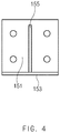
FIG. 4 is a front view illustrating the anchor unit of the container according to Embodiment 1 of the present invention. -
FIG. 5 is a left side view illustrating the anchor unit of the container according to Embodiment 1 of the present invention. -
FIG. 6 is a partial perspective view of a container according to Embodiment 2 of the present invention. - Preferred embodiments of the present invention will be described below in more detail with reference to the accompanying drawings. However, the present invention is not limited to the embodiments below.
-
FIG. 1 is a perspective view of a container according to Embodiment 1 of the present invention.FIG. 2 is a plan view of the container ofFIG. 1 .FIG. 3 is a plan view illustrating an anchor unit of the container according to Embodiment 1 of the present invention.FIG. 4 is a front view illustrating the anchor unit of the container according to Embodiment 1 of the present invention.FIG. 5 is a left side view illustrating the anchor unit of the container according to Embodiment 1 of the present invention. - Hereinafter, a container according to Embodiment 1 of the present invention will be described with reference to
FIGS. 1 to 5 . - Referring to
FIGS. 1 and2 , the container according to Embodiment 1 of the present invention comprises abottom part 110, aceiling part 111, asidewall part 113, and arack 120. - The
rack 120 is configured to load a battery. Therack 120 may comprise a support (not shown) on which the battery is placed. Also, the inside of therack 120 is divided to be partitioned into predetermined spaces. - The
bottom part 110 may have a bottom surface on which therack 120 is placed. Theceiling part 111 is disposed above thebottom part 110 to face thebottom part 110. - The
sidewall part 113 may connect thebottom part 110 to theceiling part 111. Thesidewall part 113 may be configured to support theceiling part 111 so that theceiling part 111 is dropped by gravity to thebottom part 110. Also, thesidewall part 113 may be disposed around therack 120 to surround a side surface of therack 120. - The
rack 120 may be fixed and stalled in an inner space that is surrounded by thebottom part 110, theceiling part 111, and thesidewall part 113. Thus, the container may be stably fixed without being shaken by external vibration. As a result, the battery stored in therack 120 within the container may be stably stored and maintained. - The
container 100 according to Embodiment 1 of the present invention may have several characteristics in order to prevent shaking and provide an anti-vibration property. - First, the
rack 120 may be installed to be fixed to thesidewall part 113. For example, therack 120 may be fixed to thesidewall part 113 through coupling of a bolt. Alternatively, therack 120 may be fixed to thesidewall part 113 through a constituent other than the bolt coupling. - Referring to
FIG. 2 , therack 120 may comprise a wall protrusion protruding to thesidewall part 113. Thewall protrusion 121 may be prevented from being shaken by being supported by thesidewall part 113. Thewall protrusion 121 may be supported by thesidewall part 113 in a state in which thewall protrusion 121 is inserted into a groove formed in thesidewall part 113. Particularly, thesidewall protrusion 121 may have a shape that protrudes from upper and central portions of the rack 120 (seeFIG. 1 ). Since therack 120 is fixed to thesidewall part 113 of the container, the load may be dispersed. - A plurality of
racks 120 may be connected in a line to thecontainer 100 according to Embodiment 1 of the present invention. Particularly, therack 120 may be adjacent in a longitudinal direction X of the container and arranged in a line. Also, therack 120 may be coupled to theadjacent rack 120 through a bolt. Thus, therack 120 may be more stably fixed through the bolt coupling. - More particularly, the
rack 120 may comprise aside surface part 123 coming into contact with theadjacent rack 120, and the bolt may be coupled to theside surface part 123. M6 bolts may be used to be coupled to four points on theside surface part 123. - The
container 100 according to Embodiment 1 of the present invention may comprise acrossbar 125 connecting therack 120 disposed on one side V of thebottom part 110 to therack 120 disposed on the other side W of thebottom part 110. Thecrossbar 125 may restrict relative movement of therack 120 disposed on the one side V of thebottom part 110 and therack 120 disposed on the other side W of thebottom part 110. - The
rack 120 may comprise arack post 130 vertically supporting therack 120. Thecrossbar 125 may be connected to therack post 130. Particularly, thecrossbar 125 may be connected to the uppermost portion of therack post 130. - The
rack post 130 may have a more expanded shape. This will be described in more detail. - Referring to
FIGS. 1 and2 , thecontainer 100 according to Embodiment 1 of the present invention may comprise afirst rack line 127 in which the plurality ofracks 120 disposed on the one side V of thebottom part 110 are connected to each other in a line, asecond rack line 129 in which the plurality of racks disposed on the other side W of thebottom part 110 are connected to each other in a line, and thecrossbar 125 connecting thefirst rack line 127 to thesecond rack line 129. Thecrossbar 125 may restrict relative movement of thefirst rack line 127 and thesecond rack line 129. - Also, the
first rack line 127 may comprise a firstrack line post 131 vertically supporting thefirst rack line 127, and thesecond rack line 129 may comprise a secondrack line post 133 vertically supporting thesecond rack line 129. Thecrossbar 125 may be configured to connect the firstrack line post 131 to the second rack line post 133 (seeFIG. 1 ). - When compared to one
rack 120, if the rack lines fixed to be arranged in a line are connected to each other by thecrossbar 125 as described above, the shaking of therack 120 may be more prevented to realize a more improved anti-vibration property. Particularly, when a rigid member is used as thecrossbar 125, a relative position of therack 120 may be more strongly fixed. - Also, the
crossbar 125 may connect the uppermost portion of the firstrack line post 131 to the uppermost portion of the secondrack line post 133. When thecrossbar 125 is disposed at the uppermost portion of the rack line post, the shaking may be more prevented. - The reason for this is as follows. That is, the
rack 120 coming into contact with thebottom part 110 or adhering to thebottom part 110 may be more seriously shaken as the rack120 is away from thebottom part 110. The portion adhering to thebottom part 110 may not be shaken by adhesion force or friction force. On the other hand, the largest movement may occur at the portion that is farthest from thebottom part 110 because the portion has the largest movement radius. - The portion that is farthest from the
bottom part 110 may be the uppermost portion of therack 120, and thus, the largest shaking may occur at the uppermost portion of therack 120. Thus, when thecrossbar 125 is disposed at the uppermost portion of therack 120 as described above, the shaking of therack 120 may be maximally prevented. - Furthermore, when the
crossbar 125 is disposed at the uppermost portion of the rack line post, a path between thefirst rack line 127 and thesecond rack line 129 may be secured, and thus, it may be more advantageous. - Also, referring to
FIG. 1 , thecontainer 100 according to Embodiment 1 of the present invention may further comprise a reinforcingmember 140 disposed on acorner casting part 115 at which two sides of thesidewall part 113, which meet each other at a predetermined angle, and thebottom part 110 meet each other to surround thecorner casting part 115. The reinforcingmember 140 may absorb or buffer vibration. - Also, at least one or
more anchor units 150 may be disposed between the reinforcingmember 140 disposed at a corner of one side in the longitudinal direction of thecontainer 100 and the reinforcingmember 140 disposed at a corner of the other side. - Referring to
FIG. 1 , theanchor unit 150 may be configured to support acorner part 117 at which one surface of thesidewall part 113 and thebottom part 110 meet each other. Particularly, theanchor unit 150 will be described with reference toFIGS. 1 ,3 ,4 , and5 . - The
anchor unit 150 may comprise afirst member 151 facing thefirst sidewall part 113, asecond member 153 extending from a lower end of thefirst member 151 in a direction parallel to thebottom part 110, arib member 155 connecting thefirst member 151 to thesecond member 153 and supporting thefirst member 151 and thesecond member 153, and aprotrusion member 157 protruding from thefirst member 151 to thesidewall part 113 and inserted into thesidewall part 113. - The
protrusion member 157 may be inserted into a groove formed in thesidewall part 113. Since theprotrusion member 157 is inserted into the groove, theanchor unit 150 may be more firmly coupled to thesidewall part 113. Theanchor unit 150 may be disposed between the reinforcingmembers 140 to more firmly support thecontainer 110. When theanchor unit 150 is provided compared to a case in which theanchor unit 150 is not provided, the load of thecontainer 100 may be effectively dispersed. Particularly, the dispersing effect may be improved when the effect of supporting the container at more points than when only the reinforcingmember 140 is provided. - As described above, the
container 100 according to Embodiment 1 of the present invention may comprise the characteristic constituent for preventing thecontainer 100 from being shaken and thus have the anti-vibration property that is not shaken by the vibration, and particularly, the BESS container having the ISO standard size may be realized. -
FIG. 6 is a partial perspective view of a container according to Embodiment 2 of the present invention. - The container according to Embodiment 2 of the present invention has constituents similar to those of the container according to Embodiment 1 of the present invention. However, the container according to Embodiment 2 is different from that according to Embodiment 1 in that a bracket is further provided.
- For reference, the same (equivalent) component as that according to the foregoing embodiment is given by the same (equivalent) reference symbol, and thus, their detailed description will be omitted.
- Hereinafter, the
container 200 according to Embodiment 2 of the present invention will be described with reference toFIG. 6 . - In the
container 200 according to Embodiment 2 of the present invention, a plurality of racks may be installed to be connected to each other in a line. Each of the racks may comprise arack post 230 that vertically supports the rack. - A
bracket 260 may be configured to connect and fix the rack posts 230 to each other. For this, thebracket 260 may compriseadhesion parts 260 adhering to therack post 230 and along rod part 263 connecting the plurality ofadhesion parts 260 to each other. Thebracket 260 may be installed at two points of upper and lower portions of therack post 230. - The
container 200 according to Embodiment 2 of the present invention may comprise thebracket 260 to more surely prevent thecontainer 200 from being shaken in a longitudinal direction of thecontainer 200, and thus, more secure the stability of the battery. - While the embodiments of the present invention have been described with reference to the specific embodiments, it will be apparent to those skilled in the art that various changes and modifications may be made without departing from the spirit and scope of the invention as defined in the following claims.
Claims (16)
- A container comprising:a bottom part;a ceiling part facing the bottom part;a sidewall part connecting the bottom part to the ceiling part; anda rack installed to be fixed in an inner space that is surrounded by the bottom part, the ceiling part, and the sidewall part.
- The container of claim 1, wherein the rack is installed to be fixed to the sidewall part.
- The container of claim 2, wherein the rack is fixed to the sidewall part by bolt coupling.
- The container of claim 2, wherein the rack comprises a wall protrusion protruding toward the sidewall part, and
the wall protrusion protrudes from each of upper and central portions of the rack. - The container of claim 1, wherein the rack is provided in plurality, and the plurality of racks are connected to each other in a line, and
the racks adjacent to each other are coupled to each other by a bolt. - The container of claim 5, wherein the rack has a side surface that comes into contact with the adjacent rack, and
the bolt is coupled to the side surface. - The container of claim 1, further comprising a crossbar connecting the rack disposed on one side of the bottom part to the rack disposed on the other side of the bottom part,
wherein the crossbar restricts relative movement of the rack disposed on the one side of the bottom part and the rack disposed on the other side of the bottom part. - The container of claim 7, wherein the rack comprises a rack post vertically supporting the rack, and
the crossbar is connected to the rack post. - The container of claim 8, wherein the crossbar is connected to an upmost portion of the rack post.
- The container of claim 1, further comprising:a first rack line in which a plurality racks disposed on one side of the bottom part are connected to each other in a line;a second rack line in which a plurality of racks disposed on the other side of the bottom part are connected to each other in a line; anda crossbar connecting the first rack line to the second rack line,wherein the crossbar restricts relative movement of the first rack line and the second rack line.
- The container of claim 10, wherein the first rack line comprises a first rack line post vertically supporting the first rack line,
the second rack line comprises a second rack line post vertically supporting the second rack line, and
the crossbar connecting the first rack line post to the second rack line post. - The container of claim 11, wherein the crossbar connects an uppermost portion of the first rack line post to an uppermost portion of the second rack line post.
- The container of claim 1, further comprising a reinforcing member surrounding a corner casting part at which two sides of the sidewall part, which meet each other at a predetermined angle, and the bottom part meet each other.
- The container of claim 1, further comprising an anchor unit supporting an edge at which one surface of the sidewall part and the bottom part meet each other.
- The container of claim 14, wherein the anchor unit comprises:a first member facing the sidewall part;a second member extending from a lower end of the first member in a direction parallel to the bottom part;a rib member connecting the first member to the second member and supporting the first member and the second member; anda protrusion member protruding from the first member to the sidewall part and inserted into the sidewall part.
- The container of claim 1, wherein the rack is provided in plurality, and the plurality of racks are connected to each other in a line,
each of the racks comprises a rack post vertically supporting the rack, and
the container further comprises a bracket connecting and fixing the rack posts to each other.
Applications Claiming Priority (2)
| Application Number | Priority Date | Filing Date | Title |
|---|---|---|---|
| KR1020160002043A KR102159975B1 (en) | 2016-01-07 | 2016-01-07 | Container |
| PCT/KR2017/000215 WO2017119776A1 (en) | 2016-01-07 | 2017-01-06 | Container |
Publications (3)
| Publication Number | Publication Date |
|---|---|
| EP3372529A1 true EP3372529A1 (en) | 2018-09-12 |
| EP3372529A4 EP3372529A4 (en) | 2018-12-26 |
| EP3372529B1 EP3372529B1 (en) | 2020-08-12 |
Family
ID=59273923
Family Applications (1)
| Application Number | Title | Priority Date | Filing Date |
|---|---|---|---|
| EP17736148.2A Active EP3372529B1 (en) | 2016-01-07 | 2017-01-06 | Container |
Country Status (6)
| Country | Link |
|---|---|
| US (1) | US10894498B2 (en) |
| EP (1) | EP3372529B1 (en) |
| JP (1) | JP6758665B2 (en) |
| KR (1) | KR102159975B1 (en) |
| CN (1) | CN108137225B (en) |
| WO (1) | WO2017119776A1 (en) |
Families Citing this family (8)
| Publication number | Priority date | Publication date | Assignee | Title |
|---|---|---|---|---|
| KR101924136B1 (en) | 2018-03-06 | 2019-02-22 | (주) 삼진넥스틸 | Container house with seismic device |
| KR101923558B1 (en) | 2018-03-06 | 2019-02-22 | (주) 삼진넥스틸 | Toilet for container house with earthquake-proof device |
| KR101927204B1 (en) | 2018-03-06 | 2019-03-12 | (주) 삼진넥스틸 | Toilet for container house with earthquake-proof device |
| KR101924135B1 (en) | 2018-03-06 | 2019-02-22 | (주) 삼진넥스틸 | Wall structure of container house with seismic device |
| KR20230156488A (en) * | 2022-05-06 | 2023-11-14 | 주식회사 엘지에너지솔루션 | Battery container and energy storage system including the same |
| KR20230168068A (en) * | 2022-06-03 | 2023-12-12 | 주식회사 엘지에너지솔루션 | Battery container and Energy storage system including the same |
| KR20230168069A (en) * | 2022-06-03 | 2023-12-12 | 주식회사 엘지에너지솔루션 | Battery container and Energy storage system including the same |
| KR102654399B1 (en) | 2023-11-22 | 2024-04-05 | 주식회사 에이이 | Earthquake reistant container |
Family Cites Families (24)
| Publication number | Priority date | Publication date | Assignee | Title |
|---|---|---|---|---|
| US4212405A (en) * | 1972-03-07 | 1980-07-15 | Srick Corporation | Aluminum panel container or trailer body |
| FR2577534A1 (en) | 1985-02-14 | 1986-08-22 | Weidmann Pittet Sa | NON-REUSABLE, HIGH CAPACITY INTERMODAL PACKAGING |
| JPH041118Y2 (en) | 1986-07-31 | 1992-01-14 | ||
| US4860913A (en) * | 1988-08-11 | 1989-08-29 | Bertolini William A | Cabinet restraint system for cargo container |
| GB9024672D0 (en) * | 1990-11-13 | 1991-01-02 | Palletower G B Limited | Load supporting structure |
| KR970009675B1 (en) * | 1994-10-18 | 1997-06-17 | Hyundai Electronics Ind Ltd | Method for improving decoder using eraser method |
| KR0148467B1 (en) * | 1995-08-19 | 1999-02-18 | 최재관 | Baggage rack for a railcar |
| JPH1193265A (en) * | 1997-09-17 | 1999-04-06 | Nippon Treks Kk | Portable disaster preventing warehouse |
| US6422795B2 (en) * | 1998-01-16 | 2002-07-23 | Anthony J. Holt | Cargo lash to bar |
| US6179522B1 (en) | 1999-01-07 | 2001-01-30 | The United States Of America As Represented By The Secretary Of The Navy | Mobile refuse center structure for containment and handling of hazardous materials |
| US6729098B1 (en) * | 2002-07-23 | 2004-05-04 | James F. Brennan, Jr. | Adjustable height corner fitting |
| JP3742050B2 (en) * | 2002-10-11 | 2006-02-01 | 豊田通商株式会社 | Manufacturing method of lashing metal fittings |
| CN201272579Y (en) * | 2008-04-14 | 2009-07-15 | 柳州五菱汽车工业有限公司 | Water tank and fire-fighting truck with the same |
| CN201321244Y (en) * | 2008-08-08 | 2009-10-07 | 胜狮货柜技术研发(上海)有限公司 | Rack-type container |
| US7990710B2 (en) | 2008-12-31 | 2011-08-02 | Vs Acquisition Co. Llc | Data center |
| JP5383643B2 (en) | 2010-12-28 | 2014-01-08 | 三菱重工業株式会社 | Storage rack |
| KR101255243B1 (en) * | 2011-04-15 | 2013-04-16 | 삼성에스디아이 주식회사 | Rack housing assembly and energy storage apparatus having the same |
| TW201302013A (en) * | 2011-06-20 | 2013-01-01 | Hon Hai Prec Ind Co Ltd | Container data center |
| KR101393257B1 (en) * | 2012-03-21 | 2014-05-08 | 홍경만 | A sample box retractor and liquid gas frozen storage tank having the same |
| JP2013256327A (en) * | 2012-06-13 | 2013-12-26 | Rokko Engineering Co Ltd | Rack for cargo |
| GB201214599D0 (en) | 2012-08-16 | 2012-10-03 | Beaverfit Ltd | Functional training rig kit |
| US9828172B2 (en) * | 2013-01-07 | 2017-11-28 | Eirik Skeid | Intermodal container |
| KR101381592B1 (en) * | 2013-09-04 | 2014-04-04 | 채재훈 | Container for energy storage device |
| KR101644873B1 (en) * | 2014-07-17 | 2016-08-03 | 주식회사 엘지화학 | Electric power transport system and method for transport of electric power using the same |
-
2016
- 2016-01-07 KR KR1020160002043A patent/KR102159975B1/en active IP Right Grant
-
2017
- 2017-01-06 EP EP17736148.2A patent/EP3372529B1/en active Active
- 2017-01-06 WO PCT/KR2017/000215 patent/WO2017119776A1/en active Application Filing
- 2017-01-06 JP JP2018522044A patent/JP6758665B2/en active Active
- 2017-01-06 US US15/740,881 patent/US10894498B2/en active Active
- 2017-01-06 CN CN201780003261.0A patent/CN108137225B/en active Active
Also Published As
| Publication number | Publication date |
|---|---|
| CN108137225A (en) | 2018-06-08 |
| US10894498B2 (en) | 2021-01-19 |
| US20180339636A1 (en) | 2018-11-29 |
| KR102159975B1 (en) | 2020-09-28 |
| WO2017119776A1 (en) | 2017-07-13 |
| EP3372529B1 (en) | 2020-08-12 |
| KR20170082817A (en) | 2017-07-17 |
| JP6758665B2 (en) | 2020-09-23 |
| CN108137225B (en) | 2020-08-25 |
| JP2018535896A (en) | 2018-12-06 |
| EP3372529A4 (en) | 2018-12-26 |
Similar Documents
| Publication | Publication Date | Title |
|---|---|---|
| EP3372529B1 (en) | Container | |
| US11230221B2 (en) | Structure and method for securing and transporting equipment racks | |
| US9247660B2 (en) | Isolator system for a segmented frame for a storage drive | |
| JP2013524482A (en) | Information technology equipment and related portable information technology hosting center | |
| JP2018516819A (en) | Container binding device | |
| US20150316964A1 (en) | Segmented frame for a storage drive | |
| JP4901289B2 (en) | Pallet equipment for transporting large precision cargo | |
| AU2008325729B2 (en) | Cushioning device | |
| US20200317431A1 (en) | Casing for Transporting Communications Computers and Electronics Racks | |
| GB2518843A (en) | Shock attenuation system | |
| US8567881B2 (en) | Container data center | |
| EP2743595A2 (en) | Indoor unit for air-conditioning apparatus | |
| KR101984837B1 (en) | Pallet having fence | |
| KR20220002464U (en) | Secession preventing device and carrying box including the same | |
| JP5792102B2 (en) | Support member for workpiece | |
| CN113353420A (en) | Anti-collision device for transporting electronic elements | |
| US6695140B2 (en) | Packaging method and protective packaging system with automatic positioning component | |
| JP4863470B2 (en) | Plastic pallet | |
| KR102595523B1 (en) | Waper shipping box | |
| CN210823275U (en) | Material box frame capable of being assembled and disassembled quickly | |
| CN115214848B (en) | Ship cargo hold and container ship | |
| US20230070970A1 (en) | Substrate tray | |
| KR200400134Y1 (en) | Gate panel of loading case for a freight vehicle having internal shelf bracket | |
| KR20220001831U (en) | Eps molding support device for securing form stability of pvc thermoplastic eco-friendly fiber | |
| KR20140004857U (en) | Multi heaping space control device for carrier box |
Legal Events
| Date | Code | Title | Description |
|---|---|---|---|
| STAA | Information on the status of an ep patent application or granted ep patent |
Free format text: STATUS: THE INTERNATIONAL PUBLICATION HAS BEEN MADE |
|
| PUAI | Public reference made under article 153(3) epc to a published international application that has entered the european phase |
Free format text: ORIGINAL CODE: 0009012 |
|
| STAA | Information on the status of an ep patent application or granted ep patent |
Free format text: STATUS: REQUEST FOR EXAMINATION WAS MADE |
|
| 17P | Request for examination filed |
Effective date: 20180309 |
|
| AK | Designated contracting states |
Kind code of ref document: A1 Designated state(s): AL AT BE BG CH CY CZ DE DK EE ES FI FR GB GR HR HU IE IS IT LI LT LU LV MC MK MT NL NO PL PT RO RS SE SI SK SM TR |
|
| AX | Request for extension of the european patent |
Extension state: BA ME |
|
| A4 | Supplementary search report drawn up and despatched |
Effective date: 20181128 |
|
| RIC1 | Information provided on ipc code assigned before grant |
Ipc: B65D 90/02 20060101ALI20181123BHEP Ipc: B65D 90/00 20060101AFI20181123BHEP Ipc: E04H 5/04 20060101ALI20181123BHEP Ipc: B65D 88/12 20060101ALI20181123BHEP |
|
| DAV | Request for validation of the european patent (deleted) | ||
| DAX | Request for extension of the european patent (deleted) | ||
| GRAP | Despatch of communication of intention to grant a patent |
Free format text: ORIGINAL CODE: EPIDOSNIGR1 |
|
| STAA | Information on the status of an ep patent application or granted ep patent |
Free format text: STATUS: GRANT OF PATENT IS INTENDED |
|
| INTG | Intention to grant announced |
Effective date: 20200512 |
|
| GRAS | Grant fee paid |
Free format text: ORIGINAL CODE: EPIDOSNIGR3 |
|
| GRAA | (expected) grant |
Free format text: ORIGINAL CODE: 0009210 |
|
| STAA | Information on the status of an ep patent application or granted ep patent |
Free format text: STATUS: THE PATENT HAS BEEN GRANTED |
|
| AK | Designated contracting states |
Kind code of ref document: B1 Designated state(s): AL AT BE BG CH CY CZ DE DK EE ES FI FR GB GR HR HU IE IS IT LI LT LU LV MC MK MT NL NO PL PT RO RS SE SI SK SM TR |
|
| REG | Reference to a national code |
Ref country code: CH Ref legal event code: EP |
|
| REG | Reference to a national code |
Ref country code: IE Ref legal event code: FG4D |
|
| REG | Reference to a national code |
Ref country code: DE Ref legal event code: R096 Ref document number: 602017021565 Country of ref document: DE |
|
| REG | Reference to a national code |
Ref country code: AT Ref legal event code: REF Ref document number: 1301362 Country of ref document: AT Kind code of ref document: T Effective date: 20200915 |
|
| REG | Reference to a national code |
Ref country code: LT Ref legal event code: MG4D |
|
| REG | Reference to a national code |
Ref country code: NL Ref legal event code: MP Effective date: 20200812 |
|
| PG25 | Lapsed in a contracting state [announced via postgrant information from national office to epo] |
Ref country code: NO Free format text: LAPSE BECAUSE OF FAILURE TO SUBMIT A TRANSLATION OF THE DESCRIPTION OR TO PAY THE FEE WITHIN THE PRESCRIBED TIME-LIMIT Effective date: 20201112 Ref country code: GR Free format text: LAPSE BECAUSE OF FAILURE TO SUBMIT A TRANSLATION OF THE DESCRIPTION OR TO PAY THE FEE WITHIN THE PRESCRIBED TIME-LIMIT Effective date: 20201113 Ref country code: FI Free format text: LAPSE BECAUSE OF FAILURE TO SUBMIT A TRANSLATION OF THE DESCRIPTION OR TO PAY THE FEE WITHIN THE PRESCRIBED TIME-LIMIT Effective date: 20200812 Ref country code: SE Free format text: LAPSE BECAUSE OF FAILURE TO SUBMIT A TRANSLATION OF THE DESCRIPTION OR TO PAY THE FEE WITHIN THE PRESCRIBED TIME-LIMIT Effective date: 20200812 Ref country code: BG Free format text: LAPSE BECAUSE OF FAILURE TO SUBMIT A TRANSLATION OF THE DESCRIPTION OR TO PAY THE FEE WITHIN THE PRESCRIBED TIME-LIMIT Effective date: 20201112 Ref country code: LT Free format text: LAPSE BECAUSE OF FAILURE TO SUBMIT A TRANSLATION OF THE DESCRIPTION OR TO PAY THE FEE WITHIN THE PRESCRIBED TIME-LIMIT Effective date: 20200812 Ref country code: HR Free format text: LAPSE BECAUSE OF FAILURE TO SUBMIT A TRANSLATION OF THE DESCRIPTION OR TO PAY THE FEE WITHIN THE PRESCRIBED TIME-LIMIT Effective date: 20200812 |
|
| REG | Reference to a national code |
Ref country code: AT Ref legal event code: MK05 Ref document number: 1301362 Country of ref document: AT Kind code of ref document: T Effective date: 20200812 |
|
| PG25 | Lapsed in a contracting state [announced via postgrant information from national office to epo] |
Ref country code: IS Free format text: LAPSE BECAUSE OF FAILURE TO SUBMIT A TRANSLATION OF THE DESCRIPTION OR TO PAY THE FEE WITHIN THE PRESCRIBED TIME-LIMIT Effective date: 20201212 Ref country code: PL Free format text: LAPSE BECAUSE OF FAILURE TO SUBMIT A TRANSLATION OF THE DESCRIPTION OR TO PAY THE FEE WITHIN THE PRESCRIBED TIME-LIMIT Effective date: 20200812 Ref country code: RS Free format text: LAPSE BECAUSE OF FAILURE TO SUBMIT A TRANSLATION OF THE DESCRIPTION OR TO PAY THE FEE WITHIN THE PRESCRIBED TIME-LIMIT Effective date: 20200812 Ref country code: LV Free format text: LAPSE BECAUSE OF FAILURE TO SUBMIT A TRANSLATION OF THE DESCRIPTION OR TO PAY THE FEE WITHIN THE PRESCRIBED TIME-LIMIT Effective date: 20200812 Ref country code: NL Free format text: LAPSE BECAUSE OF FAILURE TO SUBMIT A TRANSLATION OF THE DESCRIPTION OR TO PAY THE FEE WITHIN THE PRESCRIBED TIME-LIMIT Effective date: 20200812 |
|
| PG25 | Lapsed in a contracting state [announced via postgrant information from national office to epo] |
Ref country code: EE Free format text: LAPSE BECAUSE OF FAILURE TO SUBMIT A TRANSLATION OF THE DESCRIPTION OR TO PAY THE FEE WITHIN THE PRESCRIBED TIME-LIMIT Effective date: 20200812 Ref country code: SM Free format text: LAPSE BECAUSE OF FAILURE TO SUBMIT A TRANSLATION OF THE DESCRIPTION OR TO PAY THE FEE WITHIN THE PRESCRIBED TIME-LIMIT Effective date: 20200812 Ref country code: CZ Free format text: LAPSE BECAUSE OF FAILURE TO SUBMIT A TRANSLATION OF THE DESCRIPTION OR TO PAY THE FEE WITHIN THE PRESCRIBED TIME-LIMIT Effective date: 20200812 Ref country code: DK Free format text: LAPSE BECAUSE OF FAILURE TO SUBMIT A TRANSLATION OF THE DESCRIPTION OR TO PAY THE FEE WITHIN THE PRESCRIBED TIME-LIMIT Effective date: 20200812 Ref country code: RO Free format text: LAPSE BECAUSE OF FAILURE TO SUBMIT A TRANSLATION OF THE DESCRIPTION OR TO PAY THE FEE WITHIN THE PRESCRIBED TIME-LIMIT Effective date: 20200812 |
|
| REG | Reference to a national code |
Ref country code: DE Ref legal event code: R097 Ref document number: 602017021565 Country of ref document: DE |
|
| PG25 | Lapsed in a contracting state [announced via postgrant information from national office to epo] |
Ref country code: ES Free format text: LAPSE BECAUSE OF FAILURE TO SUBMIT A TRANSLATION OF THE DESCRIPTION OR TO PAY THE FEE WITHIN THE PRESCRIBED TIME-LIMIT Effective date: 20200812 Ref country code: AL Free format text: LAPSE BECAUSE OF FAILURE TO SUBMIT A TRANSLATION OF THE DESCRIPTION OR TO PAY THE FEE WITHIN THE PRESCRIBED TIME-LIMIT Effective date: 20200812 Ref country code: AT Free format text: LAPSE BECAUSE OF FAILURE TO SUBMIT A TRANSLATION OF THE DESCRIPTION OR TO PAY THE FEE WITHIN THE PRESCRIBED TIME-LIMIT Effective date: 20200812 |
|
| PLBE | No opposition filed within time limit |
Free format text: ORIGINAL CODE: 0009261 |
|
| STAA | Information on the status of an ep patent application or granted ep patent |
Free format text: STATUS: NO OPPOSITION FILED WITHIN TIME LIMIT |
|
| PG25 | Lapsed in a contracting state [announced via postgrant information from national office to epo] |
Ref country code: SK Free format text: LAPSE BECAUSE OF FAILURE TO SUBMIT A TRANSLATION OF THE DESCRIPTION OR TO PAY THE FEE WITHIN THE PRESCRIBED TIME-LIMIT Effective date: 20200812 |
|
| 26N | No opposition filed |
Effective date: 20210514 |
|
| PG25 | Lapsed in a contracting state [announced via postgrant information from national office to epo] |
Ref country code: IT Free format text: LAPSE BECAUSE OF FAILURE TO SUBMIT A TRANSLATION OF THE DESCRIPTION OR TO PAY THE FEE WITHIN THE PRESCRIBED TIME-LIMIT Effective date: 20200812 |
|
| PG25 | Lapsed in a contracting state [announced via postgrant information from national office to epo] |
Ref country code: SI Free format text: LAPSE BECAUSE OF FAILURE TO SUBMIT A TRANSLATION OF THE DESCRIPTION OR TO PAY THE FEE WITHIN THE PRESCRIBED TIME-LIMIT Effective date: 20200812 Ref country code: MC Free format text: LAPSE BECAUSE OF FAILURE TO SUBMIT A TRANSLATION OF THE DESCRIPTION OR TO PAY THE FEE WITHIN THE PRESCRIBED TIME-LIMIT Effective date: 20200812 |
|
| REG | Reference to a national code |
Ref country code: CH Ref legal event code: PL |
|
| PG25 | Lapsed in a contracting state [announced via postgrant information from national office to epo] |
Ref country code: LU Free format text: LAPSE BECAUSE OF NON-PAYMENT OF DUE FEES Effective date: 20210106 |
|
| REG | Reference to a national code |
Ref country code: BE Ref legal event code: MM Effective date: 20210131 |
|
| PG25 | Lapsed in a contracting state [announced via postgrant information from national office to epo] |
Ref country code: LI Free format text: LAPSE BECAUSE OF NON-PAYMENT OF DUE FEES Effective date: 20210131 Ref country code: CH Free format text: LAPSE BECAUSE OF NON-PAYMENT OF DUE FEES Effective date: 20210131 |
|
| PG25 | Lapsed in a contracting state [announced via postgrant information from national office to epo] |
Ref country code: IE Free format text: LAPSE BECAUSE OF NON-PAYMENT OF DUE FEES Effective date: 20210106 |
|
| PG25 | Lapsed in a contracting state [announced via postgrant information from national office to epo] |
Ref country code: BE Free format text: LAPSE BECAUSE OF NON-PAYMENT OF DUE FEES Effective date: 20210131 |
|
| PG25 | Lapsed in a contracting state [announced via postgrant information from national office to epo] |
Ref country code: PT Free format text: LAPSE BECAUSE OF FAILURE TO SUBMIT A TRANSLATION OF THE DESCRIPTION OR TO PAY THE FEE WITHIN THE PRESCRIBED TIME-LIMIT Effective date: 20201214 |
|
| REG | Reference to a national code |
Ref country code: DE Ref legal event code: R081 Ref document number: 602017021565 Country of ref document: DE Owner name: LG ENERGY SOLUTION, LTD., KR Free format text: FORMER OWNER: LG CHEM, LTD., SEOUL, KR |
|
| PGFP | Annual fee paid to national office [announced via postgrant information from national office to epo] |
Ref country code: DE Payment date: 20221220 Year of fee payment: 7 |
|
| P01 | Opt-out of the competence of the unified patent court (upc) registered |
Effective date: 20230512 |
|
| PG25 | Lapsed in a contracting state [announced via postgrant information from national office to epo] |
Ref country code: CY Free format text: LAPSE BECAUSE OF FAILURE TO SUBMIT A TRANSLATION OF THE DESCRIPTION OR TO PAY THE FEE WITHIN THE PRESCRIBED TIME-LIMIT Effective date: 20200812 |
|
| PG25 | Lapsed in a contracting state [announced via postgrant information from national office to epo] |
Ref country code: HU Free format text: LAPSE BECAUSE OF FAILURE TO SUBMIT A TRANSLATION OF THE DESCRIPTION OR TO PAY THE FEE WITHIN THE PRESCRIBED TIME-LIMIT; INVALID AB INITIO Effective date: 20170106 |
|
| REG | Reference to a national code |
Ref country code: GB Ref legal event code: 732E Free format text: REGISTERED BETWEEN 20230824 AND 20230831 |
|
| PGFP | Annual fee paid to national office [announced via postgrant information from national office to epo] |
Ref country code: GB Payment date: 20231220 Year of fee payment: 8 |
|
| PGFP | Annual fee paid to national office [announced via postgrant information from national office to epo] |
Ref country code: FR Payment date: 20231222 Year of fee payment: 8 |
|
| PG25 | Lapsed in a contracting state [announced via postgrant information from national office to epo] |
Ref country code: MK Free format text: LAPSE BECAUSE OF FAILURE TO SUBMIT A TRANSLATION OF THE DESCRIPTION OR TO PAY THE FEE WITHIN THE PRESCRIBED TIME-LIMIT Effective date: 20200812 |
|
| PGFP | Annual fee paid to national office [announced via postgrant information from national office to epo] |
Ref country code: DE Payment date: 20231220 Year of fee payment: 8 |