EP3372469A1 - Door apparatus and the vehicle equipped therewith - Google Patents
Door apparatus and the vehicle equipped therewith Download PDFInfo
- Publication number
- EP3372469A1 EP3372469A1 EP18160614.6A EP18160614A EP3372469A1 EP 3372469 A1 EP3372469 A1 EP 3372469A1 EP 18160614 A EP18160614 A EP 18160614A EP 3372469 A1 EP3372469 A1 EP 3372469A1
- Authority
- EP
- European Patent Office
- Prior art keywords
- door
- receiving portion
- movable receiving
- opening
- opening frame
- Prior art date
- Legal status (The legal status is an assumption and is not a legal conclusion. Google has not performed a legal analysis and makes no representation as to the accuracy of the status listed.)
- Granted
Links
Images









Classifications
-
- B—PERFORMING OPERATIONS; TRANSPORTING
- B61—RAILWAYS
- B61D—BODY DETAILS OR KINDS OF RAILWAY VEHICLES
- B61D19/00—Door arrangements specially adapted for rail vehicles
- B61D19/003—Door arrangements specially adapted for rail vehicles characterised by the movements of the door
- B61D19/008—Door arrangements specially adapted for rail vehicles characterised by the movements of the door both swinging and sliding
-
- B—PERFORMING OPERATIONS; TRANSPORTING
- B61—RAILWAYS
- B61D—BODY DETAILS OR KINDS OF RAILWAY VEHICLES
- B61D19/00—Door arrangements specially adapted for rail vehicles
- B61D19/003—Door arrangements specially adapted for rail vehicles characterised by the movements of the door
-
- B—PERFORMING OPERATIONS; TRANSPORTING
- B61—RAILWAYS
- B61D—BODY DETAILS OR KINDS OF RAILWAY VEHICLES
- B61D19/00—Door arrangements specially adapted for rail vehicles
- B61D19/02—Door arrangements specially adapted for rail vehicles for carriages
-
- E—FIXED CONSTRUCTIONS
- E06—DOORS, WINDOWS, SHUTTERS, OR ROLLER BLINDS IN GENERAL; LADDERS
- E06B—FIXED OR MOVABLE CLOSURES FOR OPENINGS IN BUILDINGS, VEHICLES, FENCES OR LIKE ENCLOSURES IN GENERAL, e.g. DOORS, WINDOWS, BLINDS, GATES
- E06B1/00—Border constructions of openings in walls, floors, or ceilings; Frames to be rigidly mounted in such openings
- E06B1/04—Frames for doors, windows, or the like to be fixed in openings
- E06B1/52—Frames specially adapted for doors
-
- E—FIXED CONSTRUCTIONS
- E06—DOORS, WINDOWS, SHUTTERS, OR ROLLER BLINDS IN GENERAL; LADDERS
- E06B—FIXED OR MOVABLE CLOSURES FOR OPENINGS IN BUILDINGS, VEHICLES, FENCES OR LIKE ENCLOSURES IN GENERAL, e.g. DOORS, WINDOWS, BLINDS, GATES
- E06B1/00—Border constructions of openings in walls, floors, or ceilings; Frames to be rigidly mounted in such openings
- E06B1/70—Sills; Thresholds
-
- E—FIXED CONSTRUCTIONS
- E06—DOORS, WINDOWS, SHUTTERS, OR ROLLER BLINDS IN GENERAL; LADDERS
- E06B—FIXED OR MOVABLE CLOSURES FOR OPENINGS IN BUILDINGS, VEHICLES, FENCES OR LIKE ENCLOSURES IN GENERAL, e.g. DOORS, WINDOWS, BLINDS, GATES
- E06B7/00—Special arrangements or measures in connection with doors or windows
- E06B7/16—Sealing arrangements on wings or parts co-operating with the wings
- E06B7/22—Sealing arrangements on wings or parts co-operating with the wings by means of elastic edgings, e.g. elastic rubber tubes; by means of resilient edgings, e.g. felt or plush strips, resilient metal strips
- E06B7/23—Plastic, sponge rubber, or like strips or tubes
Definitions
- the present invention relates to a door apparatus and a vehicle equipped therewith.
- a plug door apparatus installed at an opening of a vehicle such as a railway vehicle.
- the plug door apparatus causes the door to move in a width direction of the vehicle.
- a seal surface be provided in a peripheral region of the opening of the vehicle, the peripheral region being directly opposed to the door.
- the opening is narrowed by the region in which the seal surface is provided, resulting in obstructing passage of a human or movement of an object through the opening.
- the present invention has been made in view of such circumstances, and it is an object of the present invention to provide a door apparatus capable of widening an opening when a door is opened
- a door apparatus is provided with an opening frame defining an opening, and a door for operating between a first door position and a second door position, the door making contact with the opening frame when at the first door position, the door being separated from the opening frame when at the second door position, wherein a movable receiving portion constituted by at least part of the opening frame operates so that the opening is larger when the door is at the second door position than when the door is at the first door position.
- the movable receiving portion may operate so as to narrow the opening.
- the movable receiving portion may operate in accordance with an operation of the door between the first door position and the second door position.
- the door apparatus according to the present invention may be provided further with a plug operation portion (45) for operating the door between the first door position and the second door position, and a transmission unit provided between either the plug operation portion (45) or the door and the movable receiving portion of the opening frame, the transmission unit transmitting an operation of either the plug operation portion (45) or the door to the movable receiving portion.
- a plug operation portion (45) for operating the door between the first door position and the second door position
- a transmission unit provided between either the plug operation portion (45) or the door and the movable receiving portion of the opening frame, the transmission unit transmitting an operation of either the plug operation portion (45) or the door to the movable receiving portion.
- the movable receiving portion of the opening frame may start an operation after the door has started an operation from the first door position and moved a given distance.
- the movable receiving portion of the opening frame may end an operation before the door reaches the second door position.
- the movable receiving portion of the opening frame may end an operation before the door reaches the first door position.
- the movable receiving portion may be rotatable about an axis non-parallel to a moving direction of the door between the first door position and the second door position.
- the movable receiving portion may be rotatable about an axis along an extending direction of the opening frame.
- the opening frame includes a door receiving plate portion forming a receiving surface, the receiving surface coming in contact with the door being at the first door position, and a support portion connected to the door receiving plate portion, and the movable receiving portion constitutes part of the door receiving plate portion and is operable between a first receiving portion position and a second receiving portion position, the movable receiving portion standing from the support portion when at the first receiving portion position, the movable receiving portion being lowered when at the second receiving portion position.
- the door receiving plate portion further includes a stationary receiving portion maintained in a stationary state while the door operates between the first door position and the second door position, and when the door is at the first door position, an end portion of the stationary receiving portion along an extending direction of the opening frame and an end portion of the movable receiving portion along the extending direction are directly opposed to each other in a moving direction of the door operating between the first door position and the second door position.
- a seal member may be provided between the end portion of the stationary receiving portion and the end portion of the movable receiving portion.
- the movable receiving portion being at the first receiving portion position may be tightly attached to the support portion in a region along an extending direction of the opening frame.
- the door apparatus according to the present invention may be used for a vehicle.
- a vehicle according to the present invention is provided with a vehicle body, and the above-mentioned door apparatus installed in the vehicle body.
- the present invention it is possible to widen the opening when the door is opened. Therefore, when the door is closed, airtightness of the vehicle body can be obtained by providing, at a periphery of the opening, a region that makes contact with the door, while when the door is opened, passage of a human or movement of an object through the opening can be facilitated by widening the opening.
- Fig. 1 is a plan view of a door apparatus according to this embodiment.
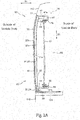
- Fig. 2A and Fig. 2B are side views of a railway vehicle having a vehicle body with the door apparatus shown in Fig. 1 installed therein.
- a railway vehicle 100 has a vehicle body 110 and a door apparatus 10 installed in the vehicle body 110.
- the door apparatus 10 is a so-called plug door apparatus in which a door 20 can be moved in a width direction (hereinafter, a "vehicle width direction") ZA (see Fig. 2A ) of the vehicle body 110.
- the door 20 is operated between a first door position shown in Fig. 2A (see Fig. 2A ) and a second door position shown in Fig. 2B .
- the door 20 is further operated in a front-rear direction (hereinafter, a "front-rear direction”) ZB of the vehicle body 110 from the second door position shown in Fig. 2B .
- a boarding/alighting assisting step board 120 is housed at the time of boarding/alighting of passengers of the railway vehicle 100.
- the boarding/alighting assisting step board 120 is stretched between the vehicle body 110 and a platform (not shown) so as to assist the passengers in their boarding/alighting.
- a platform not shown
- the boarding/alighting assisting step board 120 is drawn out from inside the vehicle body 110 toward the platform, and when the door 20 is closed, the boarding/alighting assisting step board 120 is drawn into the vehicle body 110.
- the door apparatus 10 has the door 20, a circumferential opening frame 30 fixed to the vehicle body 110, a fixed base 41 fixed to the vehicle body 110 in an area above an opening 130 defined by the opening frame 30, a plug operation portion 45 that operates the door 20 in the vehicle width direction ZA, a front-rear operation portion 47 that operates the door 20 in the front-rear direction ZB, and a door driver 44 as a drive source that drives the plug operation portion 45 and the front-rear operation portion 47.
- the plug operation portion 45 has an upper slide member 43 slidable in the vehicle width direction ZA with respect to the fixed base 41, a pair of rails 42 that supports the upper slide member 43 so that the upper slide member 43 is slidable in the vehicle width direction ZA, an upper plug operation portion 46 that operates the upper slide member 43 in the vehicle width direction ZA, and a lower plug operation portion 60 that transmits an operation of the upper slide member 43 to a lower portion of the door 20.
- the plug operation portion 45 causes the door 20 to perform an operation (hereinafter, a "plug operation") between a first door position (see Fig. 2A ) at which the door 20 makes contact with the opening frame 30 and a second door position (see Fig. 2B ) at which the door 20 is separated from the opening frame 30.
- the door apparatus 10 described here is so designed that in a case where the door 20 being at the first door position is opened, a movable receiving portion 34 constituted by at least part of the opening frame 30 operates so as to widen the opening 13 defined by the opening frame 30.
- a doorway 115 can be increased in wideness, thus making it possible to facilitate moving in and out via the door apparatus 10.
- the door apparatus 10 is applied to the railway vehicle 100. It is to be noted, however, that without any limitation to this application example, the door apparatus 10 can be broadly applied to various uses such as, for example, a door to a factory required to achieve airtightness (a door constituting a doorway of a refrigeration factory). Further, in various applications, it is also possible to enjoy an advantage of being able to facilitate moving in and out via the door apparatus 10.
- the door apparatus 10 is a so-called outside plug type door apparatus. Consequently, when the door 20 moves from the first door position at which the door 20 makes contact with the opening frame 30 to the second door position at which the door 20 is separated from the opening frame 30, the door 20 moves in a direction from inside of the vehicle body 110 toward outside thereof. On the other hand, when the door 20 moves from the second door position to the first door position, the door 20 moves in a direction from outside of the vehicle body 110 toward inside thereof.
- the fixed base 41 extends along an upper edge of the opening 130.
- the pair of rails 42 is fixed to both ends of a bottom surface of the fixed base 41 in the front-rear direction ZB of the vehicle body 110.
- the pair of rails 42 extends in the vehicle width direction ZA.
- a gap is provided between the upper slide member 43 and the fixed base 41, the upper slide member 43 being supported by the pair of rails 42 described above.
- a door guide hole 48 for restricting motion of the door 20 is provided in the fixed base 41.
- the door guide hole 48 as a whole is L-shaped and has a width direction portion 48a extending in the vehicle width direction ZA and a front-rear direction portion 48b extending in the front-rear direction ZB.
- an operation of the door 20 in the vehicle width direction ZA or in the front-rear direction ZB is restricted
- the door 20 has dimensions corresponding to dimensions of the opening 130 so as not to interfere with an operation of drawing out/in the boarding/alighting assisting step board 120.
- the door 20 has an inner surface 20a facing inside of the vehicle body 110 and an outer surface 20b facing outside of the vehicle body 110.
- a seal member 51 is provided circumferentially along an edge portion 21 of the door 20.
- a door coupling member 22 extending in the vehicle width direction ZA is fixed to an upper portion of the door 20.
- the door coupling member 22 is inserted into the gap between the upper slide member 43 and the fixed base 41. In this manner, the door 20 is suspended from between the upper slide member 43 and the fixed base 41.
- a shaft member 22a extending in the height direction ZC is provided at an end portion of the door coupling member 22 on an opposite side to the door 20.
- the shaft member 22a is disposed within the door guide hole 48 provided in the fixed base 41.
- the door driver 44 is provided on a bottom surface of the upper slide member 43 and includes a motor (not shown) and a planetary gear mechanism (not shown) that transmits a driving force of the motor to the plug operation portion 45 and to the front-rear operation portion 47. While the shaft member 22a of the door coupling member 22 is in the width direction portion 48a of the door guide hole 48, the door driver 44 distributes a driving force to the plug operation portion 45, and while the shaft member 22a of the door coupling member 22 is in the front-rear direction portion 48b of the door guide hole 48, the door driver 44 distributes a driving force to the front-rear operation portion 47.
- the plug operation portion 45 is driven by the door driver 44 described above, and thus the door 20 can perform a plug operation in the vehicle width direction ZA between the first door position shown in Fig. 2A and the second door position shown in Fig. 2B . Furthermore, the front-rear operation portion 47 is driven by the door driver 44 described above, and thus the door 20 being at the second door position is moved in the front-rear direction ZB so that the opening 130 defined by the opening frame 30, accordingly, the doorway 115 (corresponding to a boarding/alighting port in this example in which the present invention is applied to the railway vehicle 100) is exposed
- the upper plug operation portion 46 of the plug operation portion 45 is driven by the door driver 44 to operate the upper slide member 43 in the vehicle width direction ZA.
- the upper plug operation portion 46 has a rotary portion 46a rotatably fixed to the upper slide member 43 and a rack 46b fixed to a bottom surface of the fixed base 41 and extending in the vehicle width direction ZA.
- the rotary portion 46a is caused to rotate by the door driver 44.
- the rack 46b is meshed with a pinion provided on the rotary portion 46a. Consequently, the upper slide member 43 moves in the vehicle width direction ZA as the rotary portion 46a rotates.
- the lower plug operation portion 60 of the plug operation portion 45 transmits motion of the upper slide member 43 to the lower portion of the door 20.
- the lower plug operation portion 60 has a shaft 61 extending in the height direction ZC from the upper slide member 43 to a lower region of the door 20, a lower slide member 63 provided in the lower region of the door 20, a roller 63a (see Fig. 6A , etc.) provided at an end portion of the lower slide member 63 near the door 20, and a roller rail 20c provided on the door 20 along the front-rear direction ZB of the vehicle body 110.
- the shaft 61 is rotatably retained to a wall surface 111 of the vehicle body 110.
- the shaft 61 has a first pinion 61a fixed at one end portion thereof and a second pinion 61b fixed to the other end thereof.
- a first rack 62 is provided on a side surface of the upper slide member 43 so as to be meshed with the first pinion 61a of the shaft 61.
- the first rack 62 extends along a moving direction (the vehicle width direction ZA) of the upper slide member 43 and causes the shaft 61 to rotate via the first pinion 61a in accordance with motion of the upper slide member 43.
- the lower slide member 63 is provided on the wall surface 111 of the vehicle body 110 so as to be opposed to the second pinion 61b of the shaft 61.
- the lower slide member 63 is provided so as to be slidable in the vehicle width direction ZA.
- the lower slide member 63 has a second rack 65 provided so as to be meshed with the second pinion 61b.
- the second rack 65 extends along the vehicle width direction ZA and causes the lower slide member 63 to move in the vehicle width direction ZA in accordance with rotation of the shaft 61, i.e. in accordance with rotation of the second pinion 61b.
- the roller 63a is provided at the end portion of the lower slide member 63, which is opposed to the door 20.
- the roller 63a is disposed within the roller rail 20c provided on the door 20 along the front-rear direction ZB.
- the roller rail 20c has a wall portion opposed to the door 20, and the roller 63a is disposed between said wall portion and the door 20.
- the roller 63a rotates as the door 20 moves. Shaking of the door 20 is restricted by the roller rail 20c and the roller 63a described above, and thus it is possible to cause the door 20 to stably move in the vehicle width direction ZA and in the front-rear direction ZB.
- the front-rear operation portion 47 shown in Fig. 1 has a pair of pulleys 47a provided on the bottom surface of the upper slide member 43 so as to be spaced apart from each other in the front-rear direction ZB, a belt 47b wound around the pair of pulleys 47a, and a door coupling member 47c coupling the belt 47b to the door 20.
- the belt 47b is caused to rotate around the pair of pulleys 47a by the door driver 44. Rotation of the belt 47b causes the door coupling member 47c to move in the front-rear direction ZB, thus causing the door 20 to move in the front-rear direction ZB.
- the opening frame 30 has a circumferential door receiving plate portion 31 directly opposed to the door 20 being at the first door position shown in Fig. 2A and a support portion 32 connected to the door receiving plate portion 31.
- the support portion 32 extends circumferentially.
- the support portion 32 is formed generally as a plate-shaped member extending in the vehicle width direction ZA.
- the door receiving plate portion 31 is a plate-shaped member extending out in the front-rear direction ZB from an outer end of the support portion 32 in the width direction ZA.
- the door receiving plate portion 31 extends circumferentially along the circumferential support portion 32 and extends out inwardly from the circumferential support portion 32. Consequently, in a state shown in Fig. 4A , an outer edge of the opening 130 defined by the circumferential opening frame 30 is defined by the circumferential door receiving plate portion 31.
- the door receiving plate portion 31 forms a receiving surface 31a.
- the receiving surface 31a makes contact with the seal member 51 provided circumferentially on the door 20.
- the receiving surface 31a faces outside in the vehicle width direction ZA.
- the door receiving plate portion 31 has a stationary receiving portion 33 that is maintained in a stationary state during a plug operation of the door 20 and the movable receiving portion 34 that is operable during a plug operation of the door 20.
- the doorway 115 is shown by a dotted line. Normally, the doorway 115 corresponds with the opening 130 defined by the opening frame 30 shown in Fig. 4A . However, in a case where the doorway 115 is desired to be widened, part of a portion constituting the receiving surface 31a may undesirably lie in a space expected to be used as the doorway 115 thus widened In the example shown by way of illustration, preferably, the boarding/alighting assisting step board 120 is set to be equal in level to a floor surface of the vehicle body 110.
- the movable receiving portion 34 is particularly useful in such a case.
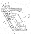
- Fig. 4B in a case where the door 20 is at the second door position shown in Fig. 2B , the movable receiving portion 34 operates, thus making it possible to widen the opening 130 so that the opening 130 corresponds with the doorway 115, in other words, to avoid a situation where the door receiving plate portion 31 defining the opening 130 stands within the doorway 115.
- Fig. 4A in a case where the door 20 is at the first door position shown in Fig.
- the movable receiving portion 34 stands within the space expected to be used as the doorway 115 closed by the door 20, forming part of the circumferential receiving surface 31a. Thus, it is possible to achieve effective airtightness between the door 20 and the vehicle body 110.
- a portion of the opening frame 30 other than the movable receiving portion 34 is hidden in structures such as a wall and a ceiling of the vehicle body 110 and thus is concealed from passengers (people passing therethrough). That is, in the example shown, the opening frame 30 is configured as a four-way frame including an upper portion, a lower portion, and a pair of side portions. Only the lower portion is operable between a position at which the lower portion lies within the space expected to be used as the doorway 115 and a position at which the lower portion is separated from the space expected to be used as the doorway 115.
- the movable receiving portion 34 is rotatable about an axis LA (in the example shown in Fig. 1 to Fig. 6C , the axis LA along an extending direction (a circumferential direction) ZD of the opening frame 30) non-parallel to the moving direction ZA of the door 20 at the time of a plug operation.
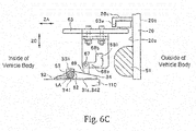
- the movable receiving portion 34 can operate between a first receiving portion position (see Fig. 6A ) at which the movable receiving portion 34 stands from the support portion 32 and a second receiving portion position at which the movable receiving portion 34 is lowered (see Fig. 6C ).
- the opening 130 defined by the circumferential opening frame 30 becomes wider than in a case where the movable receiving portion 34 is at the first receiving portion position.
- the movable receiving portion 34 shown in Fig. 1 operates between the first receiving portion position and the second receiving portion position in accordance with an operation (a plug operation) of the door 20 between the first door position and the second door position. Specifically, during a plug operation of the door 20, an operation of the plug operation portion 45 is transmitted to the movable receiving portion 34, so that in a case where the door 20 is at the first door position, the movable receiving portion 34 is positioned at the first receiving portion position shown in Fig. 6A , and in a case where the door 20 is at the second door position, the movable receiving portion 34 is at the second receiving portion position shown in Fig. 6C .
- An operation of the plug operation portion 45 is transmitted by a transmission unit 64 provided between the plug operation portion 45 and the movable receiving portion 34 of the opening frame 30.
- the transmission unit 64 may be provided between the door 20 and the movable receiving portion 34 so as to transmit an operation of the door 20 to the movable receiving portion 34.
- Fig. 5 is an enlarged perspective view showing a connection portion between the stationary receiving portion 33 and the movable receiving portion 34 of the opening frame 30.
- an end portion 331 of the stationary receiving portion 33 and an end portion 341 of the movable receiving portion 34 extend along the circumferential direction ZD of the opening frame 30 and are positioned so as to overlap each other in a partial region along the circumferential direction ZD.
- the end portion 331 of the stationary receiving portion 33 and the end portion 341 of the movable receiving portion 34 are directly opposed to each other in the moving direction ZA of the door 20 at the time of a plug operation.
- a seal member 52 is provided at the end portion 331 of the stationary receiving portion 33 so that the end portion 341 of the movable receiving portion 34 being at the first receiving portion position and the end portion 331 of the stationary receiving portion 33 are tightly attached to each other along the circumferential direction ZD of the opening frame 30. Furthermore, in a region of the support portion 32, which is directly opposed to the movable receiving portion 34 being at the first receiving portion position, a seal member 53 is provided along said circumferential direction ZD so that the movable receiving portion 34 being at the first receiving portion position and the support portion 32 are tightly attached to each other along said circumferential direction ZD.
- This configuration makes it possible to achieve effective airtightness between the stationary receiving portion 33 and the movable receiving portion 34 of the opening frame 30 and thus to achieve effective airtightness between the opening frame 30 and the door 20 in a case where the door 20 is at the first door position shown in Fig. 2A .
- the transmission unit 64 is provided between the lower slide member 63 of the plug operation portion 45 and an end portion of the movable receiving portion 34.
- the transmission unit 64 has a plate 66 fixed to the lower slide member 63 and a pin 67 fixed to one end portion of the movable receiving portion 34 and engaged with the plate 66.
- the plate 66 has an L-shaped opening 68 provided therein.
- the L-shaped opening 68 has a width direction opening region 68a extending along the vehicle width direction ZA and a height direction opening region 68b extending in the height direction ZC.
- the height direction opening region 68b extends upward from an end portion of the width direction opening region 68a near the door 20.
- a width W of the height direction opening region 68b is larger than a diameter R of the after-mentioned pin 67 and is, preferably, twice to three times larger than the diameter R.
- the pin 67 is provided on a pin base 69 protruding from the one end portion of the movable receiving portion 34 and protrudes from the pin base 69 toward the plate 66. Positioning of the plate 66 and the pin 67 is set so that when the movable receiving portion 34 is at the first receiving portion position shown in Fig. 6A , the pin 67 is positioned within the height direction opening region 68b of the plate 66, and when the movable receiving portion 34 is at the second receiving portion position shown in Fig. 6C , the pin 67 is positioned within the width direction opening region 68a.
- the movable receiving portion 34 of the opening frame 30 is at the first receiving portion position at which the movable receiving portion 34 stands from the support portion 32 of the opening frame 30 as shown in Fig. 6A .
- a surface 342 of the movable receiving portion 34 which is directly opposed to the door 20, becomes flush with the receiving surface 31a of the stationary receiving portion 33 of the opening frame 30. Consequently, the receiving surface 31a of the opening frame 30 becomes circumferential.
- the receiving surface 31a which has become circumferential as mentioned above, and the door 20 are tightly attached to each other via the seal member 51 provided circumferentially on the door 20.
- the end portion 331 of the stationary receiving portion 33 along the circumferential direction ZD and the end portion 341 of the movable receiving portion 34 along said circumferential direction ZD are directly opposed to each other in the moving direction ZA of the door 20 at the time of a plug operation. Therefore, the end portion 331 of the stationary receiving portion 33 and the end portion 341 of the movable receiving portion 34 are tightly attached to each other via the seal member 52.
- the movable receiving portion 34 is tightly attached to the support portion 32 via the seal member 53 of the opening frame 30. In this manner, the vehicle body 110 has been made airtight.
- the plug operation portion 45 is driven by the door driver 44 so that the upper slide member 43 slides in the vehicle width direction ZA along the rails 42 toward outside of the vehicle body 110.
- the door 20 suspended from between the upper slide member 43 and the fixed base 41 moves in the vehicle width direction ZA toward the second door position shown in Fig. 2B .
- the lower slide member 63 also slides toward outside of the vehicle body 110.
- the first rack 62 of the transmission unit 64 which is provided on the side surface of the upper slide member 43, also moves together with the upper slide member 43.
- the first pinion 61a provided at the one end portion of the shaft 61 rotates, so that the shaft 61 and the second pinion 61b provided at the other end of the shaft 61 also rotate.
- the transmission unit 64 operates the movable receiving portion 34.
- the plate 66 fixed to the lower slide member 63 moves toward outside of the vehicle body 110.
- the pin 67 does not make contact with the plate 66 from right after the plate 66 has started to move to a time when the plate 66 has moved a given distance. Consequently, for a given period of time after a start of a plug operation of the door 20, the movable receiving portion 34 is retained at the first receiving portion position at which the movable receiving portion 34 stands from the support portion 32.
- the opening 130 defined by the circumferential opening frame 30 becomes wider than in a case where the movable receiving portion 34 is at the first receiving portion position shown in Fig. 4A and Fig. 6A .
- the stationary receiving portion 33 of the opening frame 30 is maintained in a stationary state also during a plug operation of the door 20.
- the movable receiving portion 34 shown in Fig. 6A to Fig. 6C ends an operation before the door 20 reaches the second door position. Consequently, even after the movable receiving portion 34 has ended movement to the second receiving portion position at which the movable receiving portion 34 is towered, the plate 66 moves in accordance with movement of the door 20 to the second door position. At this time, since the pin 67 is disposed within the width direction opening region 68a of the opening 68, movement of the plate 66 is not obstructed
- the front-rear operation portion 47 is driven by the door driver 44, and thus the door 20 moves in the front-rear direction ZB with respect to the opening frame 30.
- the doorway (the boarding/alighting port) 115 is exposed
- the movable receiving portion 34 has been lowered onto the floor surface and thus does not stand and lie in the space expected to be used as the doorway 115. Consequently, the opening 130 can be increased in wideness, and it is also possible to effectively avoid a situation where the door receiving plate portion 31 protrudes therein and interferes with passage therethrough.
- the upper plug operation portion 46 is driven by the door driver 44 so that the upper slide member 43 slides in the vehicle width direction ZA along the rails 42 toward inside of the vehicle body 110.
- the door 20 suspended from between the upper slide member 43 and the fixed base 41 moves in the vehicle width direction ZA toward the first door position shown in Fig. 2A .
- the first rack 62 of the lower plug operation portion 60 which is provided on the side surface of the upper slide member 43, also moves together with the upper slide member 43.
- the first pinion 61a provided at the one end portion of the shaft 61 rotates, so that the shaft 61 and the second pinion 61b provided at the other end of the shaft 61 also rotate.
- the plate 66 fixed to the lower slide member 63 moves toward inside of the vehicle body 110.
- the pin 67 being positioned within the width direction opening region 68a of the opening 68 of the plate 66 makes contact with and moves along the edge portion 681 of the opening 68, which extends in the height direction ZC, into the height direction opening region 68b.
- the movable receiving portion 34 in a lowered state rotates about the axis LA so as to operate toward the first receiving portion position at which the movable receiving portion 34 stands.
- the movable receiving portion 34 constituting part of the opening frame 30 operates so as to narrow the opening 13 defined by the opening frame 30.
- the end portion 331 of the stationary receiving portion 33 and the end portion 341 of the movable receiving portion 34 are directly opposed to each other in the moving direction ZA of the door 20 at the time of a plug operation.
- the surface 342 of the movable receiving portion 34 which is directly opposed to the door 20, becomes flush with the receiving surface 31a of the stationary receiving portion 33 of the opening frame 30. Consequently, the receiving surface 31a of the opening frame 30 becomes circumferential (see Fig. 4A ).
- the receiving surface 31a of the opening frame 30 becomes circumferential (see Fig. 4A ).
- the receiving surface 31a of the opening frame 30, which has become circumferential, and the door 20 are tightly attached to each other via the seal member 51 provided circumferentially on the door 20.
- the end portion 331 of the stationary receiving portion 33 and the end portion 341 of the movable receiving portion 34 which is directly opposed to said end portion 331, are tightly attached to each other via the seal member 52. Furthermore, the support portion 32 and a region of the movable receiving portion 34 along the circumferential direction ZD of the opening frame 30 are tightly attached to each other via the seal member 53. In this manner, the vehicle body 110 is made airtight.
- the door apparatus 10 is provided with the opening frame 30 defining the opening 130 and the door 20 that operates between the first door position at which the door 20 makes contact with the opening frame 30 and the second door position at which the door 20 is separated from the opening frame 30.
- the movable receiving portion 34 constituted by at least part of the opening frame 30 operates so that the opening 130 is larger when the door 20 is at the second door position than when the door 20 is at the first door position.
- the opening frame 30 defining the opening 130 can be operated so that the opening 130 is widened when the door 20 is opened Therefore, when the door 20 is closed, airtightness of the vehicle body 110 can be obtained by providing, at a peripheral portion of the opening 130, a region that makes contact with the door 20. On the other hand, when the door 20 is opened, passage of a human or movement of an object through the opening 130 can be facilitated by widening the opening 130.
- an operation of widening the opening 130 of the opening frame 30 is performed in accordance with an operation of opening the door 20, and thus at the time of opening the door 20, it is possible to widen the opening 130 without performing an additional operation for operating the opening frame 30.
- the movable receiving portion 34 operates so as to narrow the opening 130.
- the opening 130 which has been widened upon opening of the door 20, without performing an additional operation for operating the opening frame 30.
- the movable receiving portion 34 operates in accordance with an operation of the door 20 between the first door position and the second door position. As a result, at the time of opening and closing the door 20, it is possible to widen and narrow the opening 130, respectively, without performing an additional operation for operating the opening frame 30.
- the door apparatus 10 is provided further with the plug operation portion 45 that operates the door 20 between the first door position and the second door position, and the transmission unit 64 that is provided between either the plug operation portion 45 or the door 20 and the movable receiving portion 34 of the opening frame 30 and transmits an operation of either the plug operation 45 or the door 20 to the movable receiving portion 34.
- the movable receiving portion 34 can be operated in accordance with a plug operation of the door 20.
- the movable receiving portion 34 of the opening frame 30 starts an operation after the door 20 has started an operation from the first door position and moved a given distance. As a result, it is possible to effectively avoid a situation where the movable receiving portion 34 collides with the door 20.
- the movable receiving portion 34 of the opening frame 30 ends an operation before the door 20 reaches the second door position.
- the door 20 is caused to move in the front-rear direction from the second door position, thus exposing the opening 130, there is prevented a phenomenon in which an operation of the movable receiving portion 34 has not ended yet, so that passage of a human or movement of an object through the opening 130 is obstructed
- the movable receiving portion 34 is rotatable about the axis LA non-parallel to the moving direction ZA of the door 20 between the first door position and the second door position. Specifically, the movable receiving portion 34 is rotatable about the axis LA along the extending direction ZD of the opening frame 30. Thus, the movable receiving portion 34 is easily operated so as to widen the opening 130 defined by the opening frame 30.
- the opening frame 30 has the circumferential door receiving plate portion 31 forming the circumferential receiving surface 31a coming in contact with the door 20 being at the first door position, and the support portion 32 connected to the door receiving plate portion 31, and the movable receiving portion 34 constitutes part of the door receiving plate portion 31 and is operable between the first receiving portion position at which the movable receiving portion 34 stands from the support portion 32 and the second receiving portion position at which the movable receiving portion 34 is lowered
- the door apparatus 10 described above using a simple configuration and a simple operation, it is possible to achieve a state where the circumferential receiving surface 31a is formed and a state where the opening 140 is widened
- the door receiving plate portion 31 further has the stationary receiving portion 33 maintained in a stationary state while the door 20 operates between the first door position and the second door position, and when the door 20 is at the first door position, the end portion 331 of the stationary receiving portion 33 along the extending direction ZD of the opening frame 30 and the end portion 341 of the movable receiving portion 34 along the extending direction ZD are directly opposed to each other in the moving direction ZA of the door 20 when operating between the first door position and the second door position. Therefore, airtightness is easily obtained between the end portion 331 of the stationary receiving portion 33 and the end portion 341 of the movable receiving portion 34.
- the seal member 52 is provided between the end portion 331 of the stationary receiving portion 33 and the end portion 341 of the movable receiving portion 34.
- the movable receiving portion 34 being at the first receiving portion position is tightly attached to the support portion 32 in a region along the extending direction ZD of the opening frame 30.
- airtightness can be obtained between the movable receiving portion 34 and the support portion 32.
- the door apparatus 10 is used for the vehicle 100.
- the opening 130 is narrowed and the door 20 is brought in contact with the opening frame 30, so that airtightness of the vehicle body 110 can be obtained
- the vehicle 100 stops and the door 20 is opened, passage of a human or movement of an object through the opening 130 can be facilitated by widening the opening 130.
- the vehicle 100 is provided with the vehicle body 110 and the above-mentioned door apparatus 10 installed in the vehicle body 110.
- the opening 130 is narrowed and the door 20 is brought in contact with the opening frame 30, so that airtightness of the vehicle body 110 can be obtained.
- the vehicle 100 stops and the door 20 is opened, passage of a human or movement of an object through the opening 130 can be facilitated by widening the opening 130.
- a transmission unit is configured differently, and other configurations are substantially the same as those in the embodiment shown in Fig. 1 to Fig. 6C .
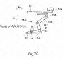
- a transmission unit 164 has a base 165 fixed to the lower slide member 63, a pin 67 fixed to one end portion of the movable receiving portion 34, and a first link plate 166 and a second link plate 167 disposed between the base 165 and the movable receiving portion 34.
- the first link plate 166 is fixed at one end portion thereof to the base 165.
- the first link plate 166 extends so that the other end portion thereof is positioned more inside of the vehicle body 110 than the one end portion thereof.
- the first link plate 166 is rotatably connected at the other end portion thereof to one end portion of the second link plate 167.
- the pin 67 of the movable receiving portion 34 is rotatably connected to the other end portion of the second link plate 167.
- the base 165 of the transmission unit 164 and the pin 67 provided at the movable receiving portion 34 are in proximity to each other. Therefore, the one end portion of the first link plate 166 and the other end portion of the second link plate 167 are in proximity to each other, and thus the first link plate 166 and the second link plate 167 are in a folded state.
- the plug operation portion 45 is driven to cause the lower slide member 63 to slide toward outside of the vehicle body 110.
- the base 165 moves toward outside of the vehicle body 110.
- the movable receiving portion 34 rotates in a direction toward the second receiving portion position shown in Fig. 7C .
- the first link plate 166 and the second link plate 167 rotate relative to each other, so that the one end portion of the first link plate 166 and the other end portion of the second link plate 167 are separated from each other.
- Fig. 7B in accordance with movement of the lower slide member 63, the base 165 moves toward outside of the vehicle body 110.
- the movable receiving portion 34 rotates in a direction toward the second receiving portion position shown in Fig. 7C .
- the first link plate 166 and the second link plate 167 rotate relative to each other, so that the one end portion of the first link plate 166 and the other end portion of the second link plate 167 are separated from each other.
- the base 165 continues to move toward outside of the vehicle body 110 while further separating the one end portion of the first link plate 166 from the other end portion of the second link plate 167.
- the base 165 stops moving when the door 20 reaches the second door position.
- the plug operation portion 45 is driven to cause the lower slide member 63 to slide toward inside of the vehicle body 110.
- the base 165 moves toward inside of the vehicle body 110.
- the movable receiving portion 34 rotates in a direction toward the first receiving portion position shown in Fig. 7A .
- the first link plate 166 and the second link plate 167 rotate relative to each other, so that they are folded while the one end portion of the first link plate 166 and the other end portion of the second link plate 167 are brought closer together.
- a transmission unit is configured differently, and other configurations are substantially the same as those in the embodiment shown in Fig. 1 to Fig. 6C .
- a transmission unit 264 has a base 265 fixed to the lower slide member 63, a pin 67 fixed to one end portion of the movable receiving portion 34, and a first link plate 266 and a second link plate 267 disposed between the base 265 and the movable receiving portion 34.
- a first pin 271 is provided at one end of the base 265. The first pin 271 protrudes substantially parallel to the front-rear direction ZB of the vehicle body 110.
- the first link plate 266 is rotatably supported at one end portion thereof by a second pin 272 projecting from the wall surface 111 of the vehicle body 110. The first link plate 266 can rotate in a plane substantially perpendicular to the front-rear direction ZB of the vehicle body 110.
- a cutout 266a is provided at the other end portion of the first link plate 266.
- the cutout 266a receives the first pin 271 provided at the base 265. While the base 265 moves, the first pin 271 is received by said cutout 266a, thus causing the first link plate 266 to rotate.
- the second link plate 267 is fixed at one end portion thereof to the one end portion of the first link plate 266.
- the second link plate 267 can rotate together with the first link plate 266 about the second pin 272.
- the second link plate 267 has, at the other end portion thereof, an opening 268 extending along a longitudinal direction of the second link plate 267.
- the pin 67 of the movable receiving portion 34 is disposed within the opening 268, and the second link plate 267 and the pin 67 are rotatable relative to each other.
- the first pin 271 provided at the base 265 of the transmission unit 264 is positioned more inside of the vehicle body 110 than the other end portion of the first link plate 266.
- the plug operation portion 45 is driven to cause the lower slide member 63 to slide toward outside of the vehicle body 110.
- the base 265 moves toward outside of the vehicle body 110.
- the first pin 271 is received by the cutout 266a of the first link plate 266, thus causing the first link plate 266 and the second link plate 267 fixed to the first link plate 266 to rotate.
- the movable receiving portion 34 rotates in a direction toward the second receiving portion position shown in Fig. 8D .
- the plug operation portion 45 is driven to cause the lower slide member 63 to slide toward inside of the vehicle body 110.
- the base 265 moves toward inside of the vehicle body 110.
- the first pin 271 is received by the cutout 266a of the first link plate 266, thus causing the first link plate 266 and the second link plate 267 fixed to the first link plate 266 to rotate.
- the movable receiving portion 34 rotates in a direction toward the first receiving portion position shown in Fig. 8A .
- a similar effect to that of the door apparatus according to the foregoing embodiment can be obtained also by the door apparatus according to the second modification example.
- the plug operation device of the second modification example in a case where the door 20 moves from the second door position to the first door position, the movable receiving portion 34 of the opening frame 30 ends an operation before the door 20 reaches the first door position. As a result, there is prevented a phenomenon in which movement of the door 20 to the first door position is obstructed by the movable receiving portion 34.
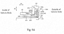
- FIG. 9A to Fig. 9C a description is given of a third modification example of the door apparatus according to the present invention.
- the third modification example shown in Fig. 9A to Fig. 9C is different in that a so-called inside plug type door apparatus is used and in that a transmission unit is configured differently.
- Other configurations are substantially the same as those in the embodiment shown in Fig. 1 to Fig. 6C .
- a door apparatus 320 shown in Fig. 9A to Fig. 9C is a so-called inside plug type door apparatus as mentioned above. Therefore, in the door apparatus 320, when the door 20 moves from the first door position shown in Fig. 9A to the second door position shown in Fig. 9C , the door 20 and the upper slide member 43 move in a direction from outside of the vehicle body 110 toward inside thereof. On the other hand, when the door 20 moves from the second door position to the first door position, the door 20 and the upper slide member 43 move in a direction from inside of the vehicle body 110 toward outside thereof. Therefore, the seal member 51 of the door 20 is provided on the outer surface 20b thereof. Furthermore, the receiving surface 31a of the opening frame 30, which is directly opposed to the door 20, faces inside of the vehicle body 110.
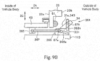
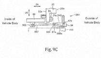
- a transmission unit 364 of the door apparatus 320 has a base 365 fixed to the lower slide member 63, a plate 366 provided adjacently to one end portion of the movable receiving portion 34, two pins 67a and 67b protruding from the one end portion of the movable receiving portion 34 toward the plate 366, and a link shaft 367 disposed between the pin 67a and the base 365.
- the plate 366 has a width direction opening 368a extending generally along the vehicle width direction ZA and a height direction opening 368b extending generally along the height direction ZC.
- the height direction opening 368b extends upward from a vicinity of an end portion of the width direction opening 368a near outside of the vehicle body 110.
- the pins 67a and 67b of the movable receiving portion 34 are disposed within the width direction opening 368a and the height direction opening 368b, respectively.
- the link shaft 367 is rotatably connected at one end thereof to the base 365 and rotatably connected at the other end thereof to the pin 67a.
- the outer surface 20b of the door 20 is directly opposed to a surface 343 of the movable receiving portion 34, which faces inside of the vehicle body 110. Furthermore, the outer surface 20b of the door 20 and said surface 343 of the movable receiving portion 34, which faces inside, are tightly attached to each other via the seal member 51.
- the plug operation portion 45 is driven to cause the lower slide member 63 to slide toward inside of the vehicle body 110.
- the base 365 moves toward inside of the vehicle body 110.
- the link shaft 367 is pulled toward inside of the vehicle body 110.
- the pins 67a and 67b of the movable receiving portion 34 move by being guided by the openings 368a and 368b, respectively.
- the movable receiving portion 34 rotates toward the second receiving portion position shown in Fig. 9C .
- the plug operation portion 45 is driven to cause the lower slide member 63 to slide toward outside of the vehicle body 110.
- the base 365 moves toward outside of the vehicle body 110.
- the link shaft 367 is pushed toward outside of the vehicle body 110.
- the pins 67a and 67b of the movable receiving portion 34 move by being guided by the openings 368a and 368b, respectively.
- the movable receiving portion 34 rotates toward the first receiving portion position shown in Fig. 9A .
- a transmission unit is configured differently, and other configurations are substantially the same as those in the embodiment shown in Fig. 1 to Fig. 6C .
- a transmission unit 464 according to the fourth modification example includes a first pinion 465 fixed to one end portion of the movable receiving portion 34, a second pinion 466 disposed in a lower region of the lower slide member 63, a chain 467 wound around the first pinion 465 and the second pinion 466, and a rack 468 fixed to a lower end portion of the lower slide member 63 so as to be opposed to the second pinion 466.
- the first pinion 465 is provided so as to be rotatable about the axis LA.
- the second pinion 466 is provided on the wall surface 111 of the vehicle body 110 and is rotatable about an axis parallel to the axis LA.
- the rack 468 causes the second pinion 466 to rotate in accordance with movement of the lower slide member 63.
- the plug operation portion 45 is driven to cause the lower slide member 63 to slide toward outside of the vehicle body 110.
- the rack 468 moves toward outside of the vehicle body 110.
- the second pinion 466 rotates in accordance with movement of the rack 468.
- the first pinion 465 rotates in tandem with the second pinion 466.
- the movable receiving portion 34 rotates to the second receiving portion position.
- the plug operation portion 45 is driven to cause the lower slide member 63 to slide toward inside of the vehicle body 110.
- the rack 468 moves toward inside of the vehicle body 110.
- the second pinion 466 rotates in accordance with movement of the rack 468.
- the first pinion 465 rotates in tandem with rotation of the second pinion 466.
- the movable receiving portion 34 rotates to the first receiving portion position.
Landscapes
- Engineering & Computer Science (AREA)
- Mechanical Engineering (AREA)
- Civil Engineering (AREA)
- Structural Engineering (AREA)
- Specific Sealing Or Ventilating Devices For Doors And Windows (AREA)
- Support Devices For Sliding Doors (AREA)
- Wing Frames And Configurations (AREA)
Abstract
Description
- The present invention relates to a door apparatus and a vehicle equipped therewith.
- Conventionally, there is known a plug door apparatus installed at an opening of a vehicle such as a railway vehicle. When a door is opened or closed, the plug door apparatus causes the door to move in a width direction of the vehicle.
- In a case of using the above-mentioned plug door apparatus, in order to increase airtightness inside the vehicle, it is required that a seal surface be provided in a peripheral region of the opening of the vehicle, the peripheral region being directly opposed to the door. In such a case, the opening is narrowed by the region in which the seal surface is provided, resulting in obstructing passage of a human or movement of an object through the opening.
- The present invention has been made in view of such circumstances, and it is an object of the present invention to provide a door apparatus capable of widening an opening when a door is opened
- A door apparatus according to the present invention is provided with an opening frame defining an opening, and a door for operating between a first door position and a second door position, the door making contact with the opening frame when at the first door position, the door being separated from the opening frame when at the second door position, wherein a movable receiving portion constituted by at least part of the opening frame operates so that the opening is larger when the door is at the second door position than when the door is at the first door position.
- In this case, when the door being at the second door position moves to the first door position, the movable receiving portion may operate so as to narrow the opening.
- Furthermore, the movable receiving portion may operate in accordance with an operation of the door between the first door position and the second door position.
- The door apparatus according to the present invention may be provided further with a plug operation portion (45) for operating the door between the first door position and the second door position, and a transmission unit provided between either the plug operation portion (45) or the door and the movable receiving portion of the opening frame, the transmission unit transmitting an operation of either the plug operation portion (45) or the door to the movable receiving portion.
- In the door apparatus according to the present invention, when the door moves from the first door position to the second door position, the movable receiving portion of the opening frame may start an operation after the door has started an operation from the first door position and moved a given distance.
- In the door apparatus according to the present invention, when the door moves from the first door position to the second door position, the movable receiving portion of the opening frame may end an operation before the door reaches the second door position.
- In the door apparatus according to the present invention, when the door moves from the second door position to the first door position, the movable receiving portion of the opening frame may end an operation before the door reaches the first door position.
- In the door apparatus according to the present invention, the movable receiving portion may be rotatable about an axis non-parallel to a moving direction of the door between the first door position and the second door position.
- In the door apparatus according to the present invention, the movable receiving portion may be rotatable about an axis along an extending direction of the opening frame.
- In the door apparatus according to the present invention, a configuration may be adopted in which the opening frame includes a door receiving plate portion forming a receiving surface, the receiving surface coming in contact with the door being at the first door position, and a support portion connected to the door receiving plate portion, and the movable receiving portion constitutes part of the door receiving plate portion and is operable between a first receiving portion position and a second receiving portion position, the movable receiving portion standing from the support portion when at the first receiving portion position, the movable receiving portion being lowered when at the second receiving portion position.
- In this case, a configuration may be adopted in which the door receiving plate portion further includes a stationary receiving portion maintained in a stationary state while the door operates between the first door position and the second door position, and when the door is at the first door position, an end portion of the stationary receiving portion along an extending direction of the opening frame and an end portion of the movable receiving portion along the extending direction are directly opposed to each other in a moving direction of the door operating between the first door position and the second door position.
- In this case, a seal member may be provided between the end portion of the stationary receiving portion and the end portion of the movable receiving portion.
- In the door apparatus according to the present invention, the movable receiving portion being at the first receiving portion position may be tightly attached to the support portion in a region along an extending direction of the opening frame.
- The door apparatus according to the present invention may be used for a vehicle.
- A vehicle according to the present invention is provided with a vehicle body, and the above-mentioned door apparatus installed in the vehicle body.
- According to the present invention, it is possible to widen the opening when the door is opened. Therefore, when the door is closed, airtightness of the vehicle body can be obtained by providing, at a periphery of the opening, a region that makes contact with the door, while when the door is opened, passage of a human or movement of an object through the opening can be facilitated by widening the opening.
-
-
Fig. 1 illustrates an embodiment of the present invention, showing a front view of a door apparatus. -
Fig. 2A is a side view showing the door apparatus in which a door shown inFig. 1 is at a first door position. -
Fig. 2B is a side view showing the door apparatus in which the door is at a second door position. -
Fig. 3 is a perspective view, on a planar side, of the door apparatus shown inFig. 1 . -
Fig. 4A is a perspective view showing an opening frame in a case where a movable receiving portion is at a first receiving portion position. -
Fig. 4B is a perspective view showing the opening frame in a case where the movable receiving portion is at a second receiving portion position. -
Fig. 5 is an enlarged perspective view showing a connection portion between a stationary portion and the movable receiving portion of the opening frame. -
Fig. 6A is a side view showing the movable receiving portion being at the first receiving portion position. -
Fig. 6B is a side view showing the movable receiving portion being between the first receiving portion position and the second receiving portion position. -
Fig. 6C is a side view showing the movable receiving portion being at the second receiving portion position. -
Fig. 7A illustrates a first modification example of the door apparatus, showing a side view of a movable receiving portion being at a first receiving portion position. -
Fig. 7B is a side view showing the movable receiving portion being between the first receiving portion position and a second receiving portion position. -
Fig. 7C is a side view showing the movable receiving portion being at the second receiving portion position. -
Fig. 8A illustrates a second modification example of the door apparatus, showing a side view of a movable receiving portion being at a first receiving portion position. -
Fig. 8B is a side view showing the movable receiving portion being between the first receiving portion position and a second receiving portion position. -
Fig. 8C is a side view showing the movable receiving portion being between a position shown inFig. 8B and the second receiving portion position. -
Fig. 8D is a side view showing the movable receiving portion being at the second receiving portion position. -
Fig. 9A illustrates a third modification example of the door apparatus, showing a side view of a movable receiving portion being at a first receiving portion position. -
Fig. 9B is a side view showing the movable receiving portion being between the first receiving portion position and a second receiving portion position. -
Fig. 9C is a side view showing the movable receiving portion being at the second receiving portion position. -
Fig. 10 illustrates a fourth modification example of the door apparatus, showing a perspective view of a rotary drive portion that rotates the movable receiving portion. - An embodiment of the present invention will now be described with reference to the appended drawings.
Fig. 1 is a plan view of a door apparatus according to this embodiment.Fig. 2A andFig. 2B are side views of a railway vehicle having a vehicle body with the door apparatus shown inFig. 1 installed therein. - As shown in
Fig. 1 , arailway vehicle 100 has avehicle body 110 and adoor apparatus 10 installed in thevehicle body 110. Thedoor apparatus 10 according to this embodiment is a so-called plug door apparatus in which adoor 20 can be moved in a width direction (hereinafter, a "vehicle width direction") ZA (seeFig. 2A ) of thevehicle body 110. Specifically, in thedoor apparatus 10 according to this embodiment, thedoor 20 is operated between a first door position shown inFig. 2A (seeFig. 2A ) and a second door position shown inFig. 2B . In thedoor apparatus 10 according to this embodiment, thedoor 20 is further operated in a front-rear direction (hereinafter, a "front-rear direction") ZB of thevehicle body 110 from the second door position shown inFig. 2B . - Furthermore, as shown in
Fig. 1 andFig. 2A , on a lower side of thedoor apparatus 10, a boarding/alighting assistingstep board 120 is housed At the time of boarding/alighting of passengers of therailway vehicle 100, the boarding/alighting assistingstep board 120 is stretched between thevehicle body 110 and a platform (not shown) so as to assist the passengers in their boarding/alighting. As shown inFig. 2B , when thedoor 20 is opened, the boarding/alighting assistingstep board 120 is drawn out from inside thevehicle body 110 toward the platform, and when thedoor 20 is closed, the boarding/alighting assistingstep board 120 is drawn into thevehicle body 110. - With reference to
Fig. 1 to Fig. 4 , the following describes in detail the door apparatus according to this embodiment. - In an example shown in
Fig. 1 to Fig. 4B , thedoor apparatus 10 has thedoor 20, acircumferential opening frame 30 fixed to thevehicle body 110, a fixedbase 41 fixed to thevehicle body 110 in an area above anopening 130 defined by theopening frame 30, aplug operation portion 45 that operates thedoor 20 in the vehicle width direction ZA, a front-rear operation portion 47 that operates thedoor 20 in the front-rear direction ZB, and adoor driver 44 as a drive source that drives theplug operation portion 45 and the front-rear operation portion 47. Theplug operation portion 45 has anupper slide member 43 slidable in the vehicle width direction ZA with respect to the fixedbase 41, a pair ofrails 42 that supports theupper slide member 43 so that theupper slide member 43 is slidable in the vehicle width direction ZA, an upperplug operation portion 46 that operates theupper slide member 43 in the vehicle width direction ZA, and a lowerplug operation portion 60 that transmits an operation of theupper slide member 43 to a lower portion of thedoor 20. Theplug operation portion 45 causes thedoor 20 to perform an operation (hereinafter, a "plug operation") between a first door position (seeFig. 2A ) at which thedoor 20 makes contact with theopening frame 30 and a second door position (seeFig. 2B ) at which thedoor 20 is separated from theopening frame 30. - Particularly, the
door apparatus 10 described here is so designed that in a case where thedoor 20 being at the first door position is opened, amovable receiving portion 34 constituted by at least part of theopening frame 30 operates so as to widen the opening 13 defined by theopening frame 30. Thus, adoorway 115 can be increased in wideness, thus making it possible to facilitate moving in and out via thedoor apparatus 10. Hereinafter, a description will be given of an example in which thedoor apparatus 10 is applied to therailway vehicle 100. It is to be noted, however, that without any limitation to this application example, thedoor apparatus 10 can be broadly applied to various uses such as, for example, a door to a factory required to achieve airtightness (a door constituting a doorway of a refrigeration factory). Further, in various applications, it is also possible to enjoy an advantage of being able to facilitate moving in and out via thedoor apparatus 10. - As is understood from
Fig. 2A andFig. 2B , thedoor apparatus 10 according to this embodiment is a so-called outside plug type door apparatus. Consequently, when thedoor 20 moves from the first door position at which thedoor 20 makes contact with theopening frame 30 to the second door position at which thedoor 20 is separated from theopening frame 30, thedoor 20 moves in a direction from inside of thevehicle body 110 toward outside thereof. On the other hand, when thedoor 20 moves from the second door position to the first door position, thedoor 20 moves in a direction from outside of thevehicle body 110 toward inside thereof. - As shown in
Fig. 1 , above theopening 130, the fixedbase 41 extends along an upper edge of theopening 130. The pair ofrails 42 is fixed to both ends of a bottom surface of the fixedbase 41 in the front-rear direction ZB of thevehicle body 110. The pair ofrails 42 extends in the vehicle width direction ZA. In a height direction (hereinafter, a "height direction") ZC of thevehicle body 110, a gap is provided between theupper slide member 43 and the fixedbase 41, theupper slide member 43 being supported by the pair ofrails 42 described above. - As shown in
Fig. 3 , adoor guide hole 48 for restricting motion of thedoor 20 is provided in the fixedbase 41. Thedoor guide hole 48 as a whole is L-shaped and has a width direction portion 48a extending in the vehicle width direction ZA and a front-rear direction portion 48b extending in the front-rear direction ZB. As will be mentioned later, by thedoor guide hole 48 described above, an operation of thedoor 20 in the vehicle width direction ZA or in the front-rear direction ZB is restricted - As is understood from
Fig. 2A andFig. 2B , thedoor 20 has dimensions corresponding to dimensions of theopening 130 so as not to interfere with an operation of drawing out/in the boarding/alighting assistingstep board 120. Thedoor 20 has aninner surface 20a facing inside of thevehicle body 110 and anouter surface 20b facing outside of thevehicle body 110. On theinner surface 20a of thedoor 20, aseal member 51 is provided circumferentially along anedge portion 21 of thedoor 20. - As shown in
Fig. 3 , adoor coupling member 22 extending in the vehicle width direction ZA is fixed to an upper portion of thedoor 20. Thedoor coupling member 22 is inserted into the gap between theupper slide member 43 and the fixedbase 41. In this manner, thedoor 20 is suspended from between theupper slide member 43 and the fixedbase 41. - A
shaft member 22a extending in the height direction ZC is provided at an end portion of thedoor coupling member 22 on an opposite side to thedoor 20. Theshaft member 22a is disposed within thedoor guide hole 48 provided in the fixedbase 41. Thus, an operation of thedoor 20 is restricted in the vehicle width direction ZA or in the front-rear direction ZB. - The
door driver 44 is provided on a bottom surface of theupper slide member 43 and includes a motor (not shown) and a planetary gear mechanism (not shown) that transmits a driving force of the motor to theplug operation portion 45 and to the front-rear operation portion 47. While theshaft member 22a of thedoor coupling member 22 is in the width direction portion 48a of thedoor guide hole 48, thedoor driver 44 distributes a driving force to theplug operation portion 45, and while theshaft member 22a of thedoor coupling member 22 is in the front-rear direction portion 48b of thedoor guide hole 48, thedoor driver 44 distributes a driving force to the front-rear operation portion 47. Theplug operation portion 45 is driven by thedoor driver 44 described above, and thus thedoor 20 can perform a plug operation in the vehicle width direction ZA between the first door position shown inFig. 2A and the second door position shown inFig. 2B . Furthermore, the front-rear operation portion 47 is driven by thedoor driver 44 described above, and thus thedoor 20 being at the second door position is moved in the front-rear direction ZB so that theopening 130 defined by theopening frame 30, accordingly, the doorway 115 (corresponding to a boarding/alighting port in this example in which the present invention is applied to the railway vehicle 100) is exposed - The upper
plug operation portion 46 of theplug operation portion 45 is driven by thedoor driver 44 to operate theupper slide member 43 in the vehicle width direction ZA. The upperplug operation portion 46 has arotary portion 46a rotatably fixed to theupper slide member 43 and arack 46b fixed to a bottom surface of the fixedbase 41 and extending in the vehicle width direction ZA. Therotary portion 46a is caused to rotate by thedoor driver 44. Therack 46b is meshed with a pinion provided on therotary portion 46a. Consequently, theupper slide member 43 moves in the vehicle width direction ZA as therotary portion 46a rotates. - The lower
plug operation portion 60 of theplug operation portion 45 transmits motion of theupper slide member 43 to the lower portion of thedoor 20. The lowerplug operation portion 60 has ashaft 61 extending in the height direction ZC from theupper slide member 43 to a lower region of thedoor 20, alower slide member 63 provided in the lower region of thedoor 20, aroller 63a (seeFig. 6A , etc.) provided at an end portion of thelower slide member 63 near thedoor 20, and aroller rail 20c provided on thedoor 20 along the front-rear direction ZB of thevehicle body 110. - The
shaft 61 is rotatably retained to awall surface 111 of thevehicle body 110. Theshaft 61 has afirst pinion 61a fixed at one end portion thereof and asecond pinion 61b fixed to the other end thereof. - A
first rack 62 is provided on a side surface of theupper slide member 43 so as to be meshed with thefirst pinion 61a of theshaft 61. Thefirst rack 62 extends along a moving direction (the vehicle width direction ZA) of theupper slide member 43 and causes theshaft 61 to rotate via thefirst pinion 61a in accordance with motion of theupper slide member 43. - The
lower slide member 63 is provided on thewall surface 111 of thevehicle body 110 so as to be opposed to thesecond pinion 61b of theshaft 61. Thelower slide member 63 is provided so as to be slidable in the vehicle width direction ZA. Thelower slide member 63 has asecond rack 65 provided so as to be meshed with thesecond pinion 61b. Thesecond rack 65 extends along the vehicle width direction ZA and causes thelower slide member 63 to move in the vehicle width direction ZA in accordance with rotation of theshaft 61, i.e. in accordance with rotation of thesecond pinion 61b. - As shown in
Fig. 6A to Fig. 6B , theroller 63a is provided at the end portion of thelower slide member 63, which is opposed to thedoor 20. Theroller 63a is disposed within theroller rail 20c provided on thedoor 20 along the front-rear direction ZB. Theroller rail 20c has a wall portion opposed to thedoor 20, and theroller 63a is disposed between said wall portion and thedoor 20. Furthermore, when thedoor 20 moves in the front-rear direction ZB, theroller 63a rotates as thedoor 20 moves. Shaking of thedoor 20 is restricted by theroller rail 20c and theroller 63a described above, and thus it is possible to cause thedoor 20 to stably move in the vehicle width direction ZA and in the front-rear direction ZB. - The front-rear operation portion 47 shown in
Fig. 1 has a pair ofpulleys 47a provided on the bottom surface of theupper slide member 43 so as to be spaced apart from each other in the front-rear direction ZB, a belt 47b wound around the pair ofpulleys 47a, and adoor coupling member 47c coupling the belt 47b to thedoor 20. The belt 47b is caused to rotate around the pair ofpulleys 47a by thedoor driver 44. Rotation of the belt 47b causes thedoor coupling member 47c to move in the front-rear direction ZB, thus causing thedoor 20 to move in the front-rear direction ZB. - The
opening frame 30 has a circumferential door receivingplate portion 31 directly opposed to thedoor 20 being at the first door position shown inFig. 2A and asupport portion 32 connected to the door receivingplate portion 31. In the example shown inFig. 4A , thesupport portion 32 extends circumferentially. Thesupport portion 32 is formed generally as a plate-shaped member extending in the vehicle width direction ZA. In this example, the door receivingplate portion 31 is a plate-shaped member extending out in the front-rear direction ZB from an outer end of thesupport portion 32 in the width direction ZA. Particularly, in the example shown, the door receivingplate portion 31 extends circumferentially along thecircumferential support portion 32 and extends out inwardly from thecircumferential support portion 32. Consequently, in a state shown inFig. 4A , an outer edge of theopening 130 defined by thecircumferential opening frame 30 is defined by the circumferential door receivingplate portion 31. - As shown in
Fig. 4A andFig. 4B , the door receivingplate portion 31 forms a receivingsurface 31a. In a case where thedoor 20 is at the first door position shown inFig. 2A , the receivingsurface 31a makes contact with theseal member 51 provided circumferentially on thedoor 20. The receivingsurface 31a faces outside in the vehicle width direction ZA. Furthermore, as shown inFig. 4A andFig. 4B , the door receivingplate portion 31 has astationary receiving portion 33 that is maintained in a stationary state during a plug operation of thedoor 20 and the movable receivingportion 34 that is operable during a plug operation of thedoor 20. - In
Fig. 4A andFig. 4B , thedoorway 115 is shown by a dotted line. Normally, thedoorway 115 corresponds with theopening 130 defined by theopening frame 30 shown inFig. 4A . However, in a case where thedoorway 115 is desired to be widened, part of a portion constituting the receivingsurface 31a may undesirably lie in a space expected to be used as thedoorway 115 thus widened In the example shown by way of illustration, preferably, the boarding/alighting assistingstep board 120 is set to be equal in level to a floor surface of thevehicle body 110. In this case, it becomes necessary that a portion of the door receivingplate portion 31, which is positioned on a lower side, be set to lie within thedoorway 115. Themovable receiving portion 34 is particularly useful in such a case. As shown inFig. 4B , in a case where thedoor 20 is at the second door position shown inFig. 2B , the movable receivingportion 34 operates, thus making it possible to widen theopening 130 so that theopening 130 corresponds with thedoorway 115, in other words, to avoid a situation where the door receivingplate portion 31 defining theopening 130 stands within thedoorway 115. On the other hand, as shown inFig. 4A , in a case where thedoor 20 is at the first door position shown inFig. 2A , the movable receivingportion 34 stands within the space expected to be used as thedoorway 115 closed by thedoor 20, forming part of the circumferential receivingsurface 31a. Thus, it is possible to achieve effective airtightness between thedoor 20 and thevehicle body 110. - A portion of the
opening frame 30 other than the movable receivingportion 34 is hidden in structures such as a wall and a ceiling of thevehicle body 110 and thus is concealed from passengers (people passing therethrough). That is, in the example shown, theopening frame 30 is configured as a four-way frame including an upper portion, a lower portion, and a pair of side portions. Only the lower portion is operable between a position at which the lower portion lies within the space expected to be used as thedoorway 115 and a position at which the lower portion is separated from the space expected to be used as thedoorway 115. - As shown in
Fig. 6A to Fig. 6C , the movable receivingportion 34 is rotatable about an axis LA (in the example shown inFig. 1 to Fig. 6C , the axis LA along an extending direction (a circumferential direction) ZD of the opening frame 30) non-parallel to the moving direction ZA of thedoor 20 at the time of a plug operation. Themovable receiving portion 34 can operate between a first receiving portion position (seeFig. 6A ) at which the movable receivingportion 34 stands from thesupport portion 32 and a second receiving portion position at which the movable receivingportion 34 is lowered (seeFig. 6C ). As is understood also fromFig. 6A andFig. 6C , in a case where the movable receivingportion 34 is at the second receiving portion position, theopening 130 defined by thecircumferential opening frame 30 becomes wider than in a case where the movable receivingportion 34 is at the first receiving portion position. - The
movable receiving portion 34 shown inFig. 1 operates between the first receiving portion position and the second receiving portion position in accordance with an operation (a plug operation) of thedoor 20 between the first door position and the second door position. Specifically, during a plug operation of thedoor 20, an operation of theplug operation portion 45 is transmitted to the movable receivingportion 34, so that in a case where thedoor 20 is at the first door position, the movable receivingportion 34 is positioned at the first receiving portion position shown inFig. 6A , and in a case where thedoor 20 is at the second door position, the movable receivingportion 34 is at the second receiving portion position shown inFig. 6C . An operation of theplug operation portion 45 is transmitted by atransmission unit 64 provided between theplug operation portion 45 and the movable receivingportion 34 of theopening frame 30. Thetransmission unit 64 may be provided between thedoor 20 and the movable receivingportion 34 so as to transmit an operation of thedoor 20 to the movable receivingportion 34. -
Fig. 5 is an enlarged perspective view showing a connection portion between thestationary receiving portion 33 and the movable receivingportion 34 of theopening frame 30. As shown inFig. 5 , anend portion 331 of thestationary receiving portion 33 and anend portion 341 of the movable receivingportion 34 extend along the circumferential direction ZD of theopening frame 30 and are positioned so as to overlap each other in a partial region along the circumferential direction ZD. As shown inFig. 6A , in a case where the movable receivingportion 34 is at the first receiving portion position, theend portion 331 of thestationary receiving portion 33 and theend portion 341 of the movable receivingportion 34 are directly opposed to each other in the moving direction ZA of thedoor 20 at the time of a plug operation. Aseal member 52 is provided at theend portion 331 of thestationary receiving portion 33 so that theend portion 341 of the movable receivingportion 34 being at the first receiving portion position and theend portion 331 of thestationary receiving portion 33 are tightly attached to each other along the circumferential direction ZD of theopening frame 30. Furthermore, in a region of thesupport portion 32, which is directly opposed to the movable receivingportion 34 being at the first receiving portion position, aseal member 53 is provided along said circumferential direction ZD so that the movable receivingportion 34 being at the first receiving portion position and thesupport portion 32 are tightly attached to each other along said circumferential direction ZD. This configuration makes it possible to achieve effective airtightness between thestationary receiving portion 33 and the movable receivingportion 34 of theopening frame 30 and thus to achieve effective airtightness between theopening frame 30 and thedoor 20 in a case where thedoor 20 is at the first door position shown inFig. 2A . - Next, with reference to
Fig. 6A to Fig. 6C , the following describes in detail thetransmission unit 64 according to this embodiment. As shown inFig. 6A to Fig. 6C , thetransmission unit 64 is provided between thelower slide member 63 of theplug operation portion 45 and an end portion of the movable receivingportion 34. - As shown in
Fig. 6A to Fig. 6C , thetransmission unit 64 has aplate 66 fixed to thelower slide member 63 and apin 67 fixed to one end portion of the movable receivingportion 34 and engaged with theplate 66. Theplate 66 has an L-shapedopening 68 provided therein. The L-shapedopening 68 has a widthdirection opening region 68a extending along the vehicle width direction ZA and a heightdirection opening region 68b extending in the height direction ZC. The heightdirection opening region 68b extends upward from an end portion of the widthdirection opening region 68a near thedoor 20. A width W of the heightdirection opening region 68b is larger than a diameter R of the after-mentionedpin 67 and is, preferably, twice to three times larger than the diameter R. - The
pin 67 is provided on apin base 69 protruding from the one end portion of the movable receivingportion 34 and protrudes from thepin base 69 toward theplate 66. Positioning of theplate 66 and thepin 67 is set so that when the movable receivingportion 34 is at the first receiving portion position shown inFig. 6A , thepin 67 is positioned within the heightdirection opening region 68b of theplate 66, and when the movable receivingportion 34 is at the second receiving portion position shown inFig. 6C , thepin 67 is positioned within the widthdirection opening region 68a. - Next, a description is given of an effect of the door apparatus according to the first embodiment.
- First, in a case where the
door 20 is at the first door position as shown inFig. 2A , the movable receivingportion 34 of theopening frame 30 is at the first receiving portion position at which the movable receivingportion 34 stands from thesupport portion 32 of theopening frame 30 as shown inFig. 6A . At this time, asurface 342 of the movable receivingportion 34, which is directly opposed to thedoor 20, becomes flush with the receivingsurface 31a of thestationary receiving portion 33 of theopening frame 30. Consequently, the receivingsurface 31a of theopening frame 30 becomes circumferential. - In a case where the
door 20 is at the first door position as shown inFig. 2A andFig. 6A , the receivingsurface 31a, which has become circumferential as mentioned above, and thedoor 20 are tightly attached to each other via theseal member 51 provided circumferentially on thedoor 20. Furthermore, in theopening frame 30, theend portion 331 of thestationary receiving portion 33 along the circumferential direction ZD and theend portion 341 of the movable receivingportion 34 along said circumferential direction ZD are directly opposed to each other in the moving direction ZA of thedoor 20 at the time of a plug operation. Therefore, theend portion 331 of thestationary receiving portion 33 and theend portion 341 of the movable receivingportion 34 are tightly attached to each other via theseal member 52. Furthermore, the movable receivingportion 34 is tightly attached to thesupport portion 32 via theseal member 53 of theopening frame 30. In this manner, thevehicle body 110 has been made airtight. - In a case where the
door 20 being at the first door position shown inFig. 2A is opened, theplug operation portion 45 is driven by thedoor driver 44 so that theupper slide member 43 slides in the vehicle width direction ZA along therails 42 toward outside of thevehicle body 110. In accordance therewith, thedoor 20 suspended from between theupper slide member 43 and the fixedbase 41 moves in the vehicle width direction ZA toward the second door position shown inFig. 2B . - At this time, in tandem with an operation of the
upper slide member 43, thelower slide member 63 also slides toward outside of thevehicle body 110. Specifically, when theupper slide member 43 slides in the vehicle width direction ZA to outside of thevehicle body 110, thefirst rack 62 of thetransmission unit 64, which is provided on the side surface of theupper slide member 43, also moves together with theupper slide member 43. In accordance with movement of thefirst rack 62, thefirst pinion 61a provided at the one end portion of theshaft 61 rotates, so that theshaft 61 and thesecond pinion 61b provided at the other end of theshaft 61 also rotate. - When the
second pinion 61b rotates, rotation of thesecond pinion 61b is transmitted to thesecond rack 65, and thus thelower slide member 63 slides in the vehicle width direction ZA toward outside of thevehicle body 110. - In tandem with an operation of the
lower slide member 63, thetransmission unit 64 operates the movable receivingportion 34. Specifically, in accordance with movement of the lower slide member 73, theplate 66 fixed to thelower slide member 63 moves toward outside of thevehicle body 110. In this case, however, since the width W of the heightdirection opening region 68b is larger than the diameter of thepin 67, thepin 67 does not make contact with theplate 66 from right after theplate 66 has started to move to a time when theplate 66 has moved a given distance. Consequently, for a given period of time after a start of a plug operation of thedoor 20, the movable receivingportion 34 is retained at the first receiving portion position at which the movable receivingportion 34 stands from thesupport portion 32. As shown inFig. 6B , when theplate 66 moves to a predetermined position, thepin 67 being positioned within the heightdirection opening region 68b of the L-shapedopening 68 of theplate 66 makes contact with and moves along anedge portion 681 of theopening 68 into the widthdirection opening region 68a. Upon this movement of thepin 67, the movable receivingportion 34 rotates about the axis LA so as to operate toward the second receiving portion position at which the movable receivingportion 34 is lowered In this manner, in a case where thedoor 20 being at the first door position is opened, the movable receivingportion 34 constituting part of theopening frame 30 operates so as to widen theopening 130 defined by theopening frame 30. As a result, as is understood fromFig. 6A andFig. 6C , in a case where the movable receivingportion 34 is at the second receiving portion position shown inFig. 4B andFig. 6C , theopening 130 defined by thecircumferential opening frame 30 becomes wider than in a case where the movable receivingportion 34 is at the first receiving portion position shown inFig. 4A andFig. 6A . Thestationary receiving portion 33 of theopening frame 30 is maintained in a stationary state also during a plug operation of thedoor 20. - Herein, the movable receiving
portion 34 shown inFig. 6A to Fig. 6C ends an operation before thedoor 20 reaches the second door position. Consequently, even after the movable receivingportion 34 has ended movement to the second receiving portion position at which the movable receivingportion 34 is towered, theplate 66 moves in accordance with movement of thedoor 20 to the second door position. At this time, since thepin 67 is disposed within the widthdirection opening region 68a of theopening 68, movement of theplate 66 is not obstructed - After the
door 20 has moved to the second door position, the front-rear operation portion 47 is driven by thedoor driver 44, and thus thedoor 20 moves in the front-rear direction ZB with respect to theopening frame 30. Thus, the doorway (the boarding/alighting port) 115 is exposed At this time, the movable receivingportion 34 has been lowered onto the floor surface and thus does not stand and lie in the space expected to be used as thedoorway 115. Consequently, theopening 130 can be increased in wideness, and it is also possible to effectively avoid a situation where the door receivingplate portion 31 protrudes therein and interferes with passage therethrough. - On the other hand, in a case where the
door 20 being at the second door position shown inFig. 2B is closed, the upperplug operation portion 46 is driven by thedoor driver 44 so that theupper slide member 43 slides in the vehicle width direction ZA along therails 42 toward inside of thevehicle body 110. In accordance therewith, thedoor 20 suspended from between theupper slide member 43 and the fixedbase 41 moves in the vehicle width direction ZA toward the first door position shown inFig. 2A . - When the
upper slide member 43 slides in the vehicle width direction ZA, thefirst rack 62 of the lowerplug operation portion 60, which is provided on the side surface of theupper slide member 43, also moves together with theupper slide member 43. In accordance with movement of thefirst rack 62, thefirst pinion 61a provided at the one end portion of theshaft 61 rotates, so that theshaft 61 and thesecond pinion 61b provided at the other end of theshaft 61 also rotate. - When the
second pinion 61b rotates, rotation of thesecond pinion 61b is transmitted to thesecond rack 65, and thus thelower slide member 63 slides in the vehicle width direction ZA toward inside of thevehicle body 110. - As shown in
Fig. 6C andFig. 6B , in accordance with movement of thelower slide member 63, theplate 66 fixed to thelower slide member 63 moves toward inside of thevehicle body 110. When theplate 66 moves to a predetermined position, as shown inFig. 6B , thepin 67 being positioned within the widthdirection opening region 68a of theopening 68 of theplate 66 makes contact with and moves along theedge portion 681 of theopening 68, which extends in the height direction ZC, into the heightdirection opening region 68b. Upon this movement of thepin 67, the movable receivingportion 34 in a lowered state rotates about the axis LA so as to operate toward the first receiving portion position at which the movable receivingportion 34 stands. In this manner, in a case where thedoor 20 being at the second door position is closed, the movable receivingportion 34 constituting part of theopening frame 30 operates so as to narrow the opening 13 defined by theopening frame 30. At this time, in theopening frame 30, theend portion 331 of thestationary receiving portion 33 and theend portion 341 of the movable receivingportion 34 are directly opposed to each other in the moving direction ZA of thedoor 20 at the time of a plug operation. - When the movable receiving
portion 34 moves to the first receiving portion position shown inFig. 6A , thesurface 342 of the movable receivingportion 34, which is directly opposed to thedoor 20, becomes flush with the receivingsurface 31a of thestationary receiving portion 33 of theopening frame 30. Consequently, the receivingsurface 31a of theopening frame 30 becomes circumferential (seeFig. 4A ). As shown inFig. 6A , when thedoor 20 moves to the first door position, the receivingsurface 31a of theopening frame 30, which has become circumferential, and thedoor 20 are tightly attached to each other via theseal member 51 provided circumferentially on thedoor 20. Furthermore, in theopening frame 30, theend portion 331 of thestationary receiving portion 33 and theend portion 341 of the movable receivingportion 34, which is directly opposed to saidend portion 331, are tightly attached to each other via theseal member 52. Furthermore, thesupport portion 32 and a region of the movable receivingportion 34 along the circumferential direction ZD of theopening frame 30 are tightly attached to each other via theseal member 53. In this manner, thevehicle body 110 is made airtight. - The
door apparatus 10 according to this embodiment is provided with theopening frame 30 defining theopening 130 and thedoor 20 that operates between the first door position at which thedoor 20 makes contact with theopening frame 30 and the second door position at which thedoor 20 is separated from theopening frame 30. Themovable receiving portion 34 constituted by at least part of theopening frame 30 operates so that theopening 130 is larger when thedoor 20 is at the second door position than when thedoor 20 is at the first door position. - According to the
door apparatus 10 described above, theopening frame 30 defining theopening 130 can be operated so that theopening 130 is widened when thedoor 20 is opened Therefore, when thedoor 20 is closed, airtightness of thevehicle body 110 can be obtained by providing, at a peripheral portion of theopening 130, a region that makes contact with thedoor 20. On the other hand, when thedoor 20 is opened, passage of a human or movement of an object through theopening 130 can be facilitated by widening theopening 130. - It can be said that this working effect is useful not only for a door apparatus used for a vehicle but also for a door apparatus applied to various uses.
- Furthermore, in this embodiment, an operation of widening the
opening 130 of theopening frame 30 is performed in accordance with an operation of opening thedoor 20, and thus at the time of opening thedoor 20, it is possible to widen theopening 130 without performing an additional operation for operating theopening frame 30. - Furthermore, in the
door apparatus 10 according to this embodiment, when thedoor 20 being at the second door position moves to the first door position, the movable receivingportion 34 operates so as to narrow theopening 130. As a result, at the time of closing thedoor 20, it is possible to narrow theopening 130, which has been widened upon opening of thedoor 20, without performing an additional operation for operating theopening frame 30. - Furthermore, in the
door apparatus 10 according to this embodiment, the movable receivingportion 34 operates in accordance with an operation of thedoor 20 between the first door position and the second door position. As a result, at the time of opening and closing thedoor 20, it is possible to widen and narrow theopening 130, respectively, without performing an additional operation for operating theopening frame 30. - Specifically, the
door apparatus 10 according to this embodiment is provided further with theplug operation portion 45 that operates thedoor 20 between the first door position and the second door position, and thetransmission unit 64 that is provided between either theplug operation portion 45 or thedoor 20 and the movable receivingportion 34 of theopening frame 30 and transmits an operation of either theplug operation 45 or thedoor 20 to the movable receivingportion 34. As a result, the movable receivingportion 34 can be operated in accordance with a plug operation of thedoor 20. - Furthermore, in the
door apparatus 10 according to this embodiment, when thedoor 20 moves from the first door position to the second door position, the movable receivingportion 34 of theopening frame 30 starts an operation after thedoor 20 has started an operation from the first door position and moved a given distance. As a result, it is possible to effectively avoid a situation where the movable receivingportion 34 collides with thedoor 20. - Furthermore, in the
door apparatus 10 according to this embodiment, when thedoor 20 moves from the first door position to the second door position, the movable receivingportion 34 of theopening frame 30 ends an operation before thedoor 20 reaches the second door position. As a result, when thedoor 20 is caused to move in the front-rear direction from the second door position, thus exposing theopening 130, there is prevented a phenomenon in which an operation of the movable receivingportion 34 has not ended yet, so that passage of a human or movement of an object through theopening 130 is obstructed - Furthermore, in the
door apparatus 10 according to this embodiment, the movable receivingportion 34 is rotatable about the axis LA non-parallel to the moving direction ZA of thedoor 20 between the first door position and the second door position. Specifically, the movable receivingportion 34 is rotatable about the axis LA along the extending direction ZD of theopening frame 30. Thus, the movable receivingportion 34 is easily operated so as to widen theopening 130 defined by theopening frame 30. - Furthermore, in the
door apparatus 10 according to this embodiment, theopening frame 30 has the circumferential door receivingplate portion 31 forming the circumferential receivingsurface 31a coming in contact with thedoor 20 being at the first door position, and thesupport portion 32 connected to the door receivingplate portion 31, and the movable receivingportion 34 constitutes part of the door receivingplate portion 31 and is operable between the first receiving portion position at which the movable receivingportion 34 stands from thesupport portion 32 and the second receiving portion position at which the movable receivingportion 34 is lowered According to thedoor apparatus 10 described above, using a simple configuration and a simple operation, it is possible to achieve a state where thecircumferential receiving surface 31a is formed and a state where the opening 140 is widened - Furthermore, in the
door apparatus 10 according to this embodiment, the door receivingplate portion 31 further has thestationary receiving portion 33 maintained in a stationary state while thedoor 20 operates between the first door position and the second door position, and when thedoor 20 is at the first door position, theend portion 331 of thestationary receiving portion 33 along the extending direction ZD of theopening frame 30 and theend portion 341 of the movable receivingportion 34 along the extending direction ZD are directly opposed to each other in the moving direction ZA of thedoor 20 when operating between the first door position and the second door position. Therefore, airtightness is easily obtained between theend portion 331 of thestationary receiving portion 33 and theend portion 341 of the movable receivingportion 34. Specifically, in thedoor apparatus 10 according to this embodiment, theseal member 52 is provided between theend portion 331 of thestationary receiving portion 33 and theend portion 341 of the movable receivingportion 34. - Furthermore, in the
door apparatus 10 according to this embodiment, the movable receivingportion 34 being at the first receiving portion position is tightly attached to thesupport portion 32 in a region along the extending direction ZD of theopening frame 30. Thus, airtightness can be obtained between the movable receivingportion 34 and thesupport portion 32. - Furthermore, the
door apparatus 10 according to this embodiment is used for thevehicle 100. According to thedoor apparatus 10 described above, while thevehicle 100 travels, theopening 130 is narrowed and thedoor 20 is brought in contact with theopening frame 30, so that airtightness of thevehicle body 110 can be obtained On the other hand, when thevehicle 100 stops and thedoor 20 is opened, passage of a human or movement of an object through theopening 130 can be facilitated by widening theopening 130. - The
vehicle 100 according to this embodiment is provided with thevehicle body 110 and the above-mentioneddoor apparatus 10 installed in thevehicle body 110. According to thevehicle 100 described above, while thevehicle 100 travels, theopening 130 is narrowed and thedoor 20 is brought in contact with theopening frame 30, so that airtightness of thevehicle body 110 can be obtained. On the other hand, when thevehicle 100 stops and thedoor 20 is opened, passage of a human or movement of an object through theopening 130 can be facilitated by widening theopening 130. - Various modifications can be made to the foregoing embodiment. While referring to the appended drawings, the following describes several modification examples. In the following description and the drawings used therein, parts that can be configured in a similar manner to that in the foregoing embodiment are denoted by the same reference characters as those used for corresponding parts in the foregoing embodiment, and duplicate descriptions thereof are omitted Furthermore, when it is obvious that the working effects obtained in the foregoing embodiment can be obtained also in the modification examples, a description thereof is possibly omitted
- With reference to
Fig. 7A to Fig. 7C , a description is given of a first modification example of the door apparatus according to the present invention. In the first modification example shown inFig. 7A to Fig. 7C , a transmission unit is configured differently, and other configurations are substantially the same as those in the embodiment shown inFig. 1 to Fig. 6C . - A
transmission unit 164 according to the first modification example has a base 165 fixed to thelower slide member 63, apin 67 fixed to one end portion of the movable receivingportion 34, and afirst link plate 166 and asecond link plate 167 disposed between the base 165 and the movable receivingportion 34. Thefirst link plate 166 is fixed at one end portion thereof to thebase 165. Thefirst link plate 166 extends so that the other end portion thereof is positioned more inside of thevehicle body 110 than the one end portion thereof. Furthermore, thefirst link plate 166 is rotatably connected at the other end portion thereof to one end portion of thesecond link plate 167. Thepin 67 of the movable receivingportion 34 is rotatably connected to the other end portion of thesecond link plate 167. - Next, a description is given of an effect of the door apparatus according to the first modification example.
- First, as shown in
Fig. 7A , in a case where thedoor 20 is at the first door position and the movable receivingportion 34 of theopening frame 30 is at the first receiving portion position at which the movable receivingportion 34 stands, thebase 165 of thetransmission unit 164 and thepin 67 provided at the movable receivingportion 34 are in proximity to each other. Therefore, the one end portion of thefirst link plate 166 and the other end portion of thesecond link plate 167 are in proximity to each other, and thus thefirst link plate 166 and thesecond link plate 167 are in a folded state. - In a case where the
door 20 being at the first door position is opened, theplug operation portion 45 is driven to cause thelower slide member 63 to slide toward outside of thevehicle body 110. As shown inFig. 7B , in accordance with movement of thelower slide member 63, the base 165 moves toward outside of thevehicle body 110. When the base 165 moves toward outside of thevehicle body 110, the movable receivingportion 34 rotates in a direction toward the second receiving portion position shown inFig. 7C . At this time, thefirst link plate 166 and thesecond link plate 167 rotate relative to each other, so that the one end portion of thefirst link plate 166 and the other end portion of thesecond link plate 167 are separated from each other. As shown inFig. 7C , after the movable receivingportion 34 has moved to the second receiving portion position, thebase 165 continues to move toward outside of thevehicle body 110 while further separating the one end portion of thefirst link plate 166 from the other end portion of thesecond link plate 167. The base 165 stops moving when thedoor 20 reaches the second door position. - On the other hand, in a case where the
door 20 being at the second door position is closed, theplug operation portion 45 is driven to cause thelower slide member 63 to slide toward inside of thevehicle body 110. As shown inFig. 7C andFig. 7B , in accordance with movement of thelower slide member 63, the base 165 moves toward inside of thevehicle body 110. When the base 165 moves toward inside of thevehicle body 110, the movable receivingportion 34 rotates in a direction toward the first receiving portion position shown inFig. 7A . At this time, thefirst link plate 166 and thesecond link plate 167 rotate relative to each other, so that they are folded while the one end portion of thefirst link plate 166 and the other end portion of thesecond link plate 167 are brought closer together. - A similar effect to that of the plug operation device according to the foregoing embodiment can be obtained also by the plug operation device according to the first modification example.
- With reference to
Fig. 8A to Fig. 8D , a description is given of a second modification example of the door apparatus according to the present invention. In the second modification example shown inFig. 8A to Fig. 8D , a transmission unit is configured differently, and other configurations are substantially the same as those in the embodiment shown inFig. 1 to Fig. 6C . - A transmission unit 264 according to the second modification example has a base 265 fixed to the
lower slide member 63, apin 67 fixed to one end portion of the movable receivingportion 34, and afirst link plate 266 and asecond link plate 267 disposed between the base 265 and the movable receivingportion 34. Afirst pin 271 is provided at one end of thebase 265. Thefirst pin 271 protrudes substantially parallel to the front-rear direction ZB of thevehicle body 110. Thefirst link plate 266 is rotatably supported at one end portion thereof by asecond pin 272 projecting from thewall surface 111 of thevehicle body 110. Thefirst link plate 266 can rotate in a plane substantially perpendicular to the front-rear direction ZB of thevehicle body 110. Acutout 266a is provided at the other end portion of thefirst link plate 266. Thecutout 266a receives thefirst pin 271 provided at thebase 265. While the base 265 moves, thefirst pin 271 is received by saidcutout 266a, thus causing thefirst link plate 266 to rotate. - The
second link plate 267 is fixed at one end portion thereof to the one end portion of thefirst link plate 266. Thesecond link plate 267 can rotate together with thefirst link plate 266 about thesecond pin 272. Thesecond link plate 267 has, at the other end portion thereof, anopening 268 extending along a longitudinal direction of thesecond link plate 267. Thepin 67 of the movable receivingportion 34 is disposed within theopening 268, and thesecond link plate 267 and thepin 67 are rotatable relative to each other. - Next, a description is given of an effect of the door apparatus according to the second modification example.
- First, as shown in
Fig. 8A , in a case where thedoor 20 is at the first door position and the movable receivingportion 34 of theopening frame 30 is at the first receiving portion position at which the movable receivingportion 34 stands, thefirst pin 271 provided at thebase 265 of the transmission unit 264 is positioned more inside of thevehicle body 110 than the other end portion of thefirst link plate 266. - As shown in
Fig. 8B , in a case where thedoor 20 being at the first door position is opened, theplug operation portion 45 is driven to cause thelower slide member 63 to slide toward outside of thevehicle body 110. Thus, the base 265 moves toward outside of thevehicle body 110. As shown inFig. 8B , when the base 265 moves to a predetermined position, thefirst pin 271 is received by thecutout 266a of thefirst link plate 266, thus causing thefirst link plate 266 and thesecond link plate 267 fixed to thefirst link plate 266 to rotate. As a result of rotation of thesecond link plate 267, the movable receivingportion 34 rotates in a direction toward the second receiving portion position shown inFig. 8D . As shown inFig. 8C andFig. 8D , when thefirst pin 271 moves to a predetermined position, thefirst pin 271 is released from thecutout 266a of thefirst link plate 266. After that, the movable receivingportion 34 continues to rotate and thus moves to the second receiving portion position. The base 265 stops moving when thedoor 20 reaches the second door position. - On the other hand, in a case where the
door 20 being at the second door position is closed, theplug operation portion 45 is driven to cause thelower slide member 63 to slide toward inside of thevehicle body 110. Thus, the base 265 moves toward inside of thevehicle body 110. As shown inFig. 8D andFig. 8C , when the base 265 moves to a predetermined position, thefirst pin 271 is received by thecutout 266a of thefirst link plate 266, thus causing thefirst link plate 266 and thesecond link plate 267 fixed to thefirst link plate 266 to rotate. As a result of rotation of thesecond link plate 267, the movable receivingportion 34 rotates in a direction toward the first receiving portion position shown inFig. 8A . As shown inFig. 8B andFig. 8A , when thefirst pin 271 moves to a predetermined position, thefirst pin 271 is released from thecutout 266a of thefirst link plate 266. After that, the movable receivingportion 34 continues to rotate and thus moves to the first receiving portion position. The base 265 stops moving when thedoor 20 reaches the first door position. - A similar effect to that of the door apparatus according to the foregoing embodiment can be obtained also by the door apparatus according to the second modification example. Moreover, according to the plug operation device of the second modification example, in a case where the
door 20 moves from the second door position to the first door position, the movable receivingportion 34 of theopening frame 30 ends an operation before thedoor 20 reaches the first door position. As a result, there is prevented a phenomenon in which movement of thedoor 20 to the first door position is obstructed by the movable receivingportion 34. - Next, with reference to
Fig. 9A to Fig. 9C , a description is given of a third modification example of the door apparatus according to the present invention. The third modification example shown inFig. 9A to Fig. 9C is different in that a so-called inside plug type door apparatus is used and in that a transmission unit is configured differently. Other configurations are substantially the same as those in the embodiment shown inFig. 1 to Fig. 6C . - A door apparatus 320 shown in
Fig. 9A to Fig. 9C is a so-called inside plug type door apparatus as mentioned above. Therefore, in the door apparatus 320, when thedoor 20 moves from the first door position shown inFig. 9A to the second door position shown inFig. 9C , thedoor 20 and theupper slide member 43 move in a direction from outside of thevehicle body 110 toward inside thereof. On the other hand, when thedoor 20 moves from the second door position to the first door position, thedoor 20 and theupper slide member 43 move in a direction from inside of thevehicle body 110 toward outside thereof. Therefore, theseal member 51 of thedoor 20 is provided on theouter surface 20b thereof. Furthermore, the receivingsurface 31a of theopening frame 30, which is directly opposed to thedoor 20, faces inside of thevehicle body 110. - A
transmission unit 364 of the door apparatus 320 has a base 365 fixed to thelower slide member 63, aplate 366 provided adjacently to one end portion of the movable receivingportion 34, twopins portion 34 toward theplate 366, and alink shaft 367 disposed between thepin 67a and thebase 365. Theplate 366 has awidth direction opening 368a extending generally along the vehicle width direction ZA and a height direction opening 368b extending generally along the height direction ZC. The height direction opening 368b extends upward from a vicinity of an end portion of thewidth direction opening 368a near outside of thevehicle body 110. Thepins portion 34 are disposed within thewidth direction opening 368a and the height direction opening 368b, respectively. Thelink shaft 367 is rotatably connected at one end thereof to thebase 365 and rotatably connected at the other end thereof to thepin 67a. - Next, a description is given of an effect of the door apparatus according to the third modification example.
- First, as shown in
Fig. 9A , in a case where thedoor 20 is at the first door position and the movable receivingportion 34 of theopening frame 30 is at the first receiving portion position at which the movable receivingportion 34 stands, theouter surface 20b of thedoor 20 is directly opposed to asurface 343 of the movable receivingportion 34, which faces inside of thevehicle body 110. Furthermore, theouter surface 20b of thedoor 20 and saidsurface 343 of the movable receivingportion 34, which faces inside, are tightly attached to each other via theseal member 51. - In a case where the
door 20 being at the first door position is opened, as shown inFig. 9B , theplug operation portion 45 is driven to cause thelower slide member 63 to slide toward inside of thevehicle body 110. Thus, the base 365 moves toward inside of thevehicle body 110. As shown inFig. 9B , in accordance with movement of thebase 365, thelink shaft 367 is pulled toward inside of thevehicle body 110. Thus, thepins portion 34 move by being guided by theopenings portion 34 rotates toward the second receiving portion position shown inFig. 9C . - On the other hand, in a case where the
door 20 being at the second door position is closed, as shown inFig. 9B , theplug operation portion 45 is driven to cause thelower slide member 63 to slide toward outside of thevehicle body 110. Thus, the base 365 moves toward outside of thevehicle body 110. As shown inFig. 9B , in accordance with movement of thebase 365, thelink shaft 367 is pushed toward outside of thevehicle body 110. Thus, thepins portion 34 move by being guided by theopenings portion 34 rotates toward the first receiving portion position shown inFig. 9A . - A similar effect to that of the door apparatus according to the foregoing embodiment can be obtained also by the door apparatus according to the third modification example.
- Next, with reference to
Fig. 10 , a description is given of a fourth modification example of the door apparatus according to the present invention. In the fourth modification example shown inFig. 10 , a transmission unit is configured differently, and other configurations are substantially the same as those in the embodiment shown inFig. 1 to Fig. 6C . - A
transmission unit 464 according to the fourth modification example includes afirst pinion 465 fixed to one end portion of the movable receivingportion 34, asecond pinion 466 disposed in a lower region of thelower slide member 63, achain 467 wound around thefirst pinion 465 and thesecond pinion 466, and arack 468 fixed to a lower end portion of thelower slide member 63 so as to be opposed to thesecond pinion 466. - The
first pinion 465 is provided so as to be rotatable about the axis LA. Thesecond pinion 466 is provided on thewall surface 111 of thevehicle body 110 and is rotatable about an axis parallel to the axis LA. Therack 468 causes thesecond pinion 466 to rotate in accordance with movement of thelower slide member 63. - Next, a description is given of an effect of the door apparatus according to the fourth modification example.
- In a case where the
door 20 being at the first door position is opened, theplug operation portion 45 is driven to cause thelower slide member 63 to slide toward outside of thevehicle body 110. Thus, therack 468 moves toward outside of thevehicle body 110. Thesecond pinion 466 rotates in accordance with movement of therack 468 Thefirst pinion 465 rotates in tandem with thesecond pinion 466. As a result of rotation of thefirst pinion 465, the movable receivingportion 34 rotates to the second receiving portion position. - On the other hand, in a case where the
door 20 being at the second door position is closed, theplug operation portion 45 is driven to cause thelower slide member 63 to slide toward inside of thevehicle body 110. Thus, therack 468 moves toward inside of thevehicle body 110. Thesecond pinion 466 rotates in accordance with movement of therack 468 Thefirst pinion 465 rotates in tandem with rotation of thesecond pinion 466. As a result of rotation of thefirst pinion 465, the movable receivingportion 34 rotates to the first receiving portion position. - A similar effect to that of the door apparatus according to the foregoing embodiment can be obtained also by the door apparatus according to the fourth modification example.
- The embodiment of the present invention and several modification examples with respect to said embodiment described thus far are illustrative and not intended to limit the scope of the invention. This new embodiment and its modification examples may have various other forms and are susceptible to omission, replacement, and modification of various elements thereof within the scope of the invention. The foregoing embodiment and its variations are included in the scope and purport of the invention and are also included in the inventions recited in the claims and equivalents thereof.
Claims (15)
- A door apparatus (10), comprising:an opening frame (30) defining an opening (130); anda door (20) for operating between a first door position and a second door position, the door (20) making contact with the opening frame (30) when at the first door position, the door (20) being separated from the opening frame (30) when at the second door position,wherein a movable receiving portion (34) constituted by at least part of the opening frame (30) operates so that the opening (130) is larger when the door (20) is at the second door position than when the door (20) is at the first door position.
- The door apparatus (10) according to claim 1, wherein when the door (20) moves from the second door position to the first door position, the movable receiving portion (34) operates so as to narrow the opening (130).
- The door apparatus (10) according to claim 1, wherein the movable receiving portion (34) operates in accordance with an operation of the door (20) between the first door position and the second door position.
- The door apparatus (10) according to claim 1, further comprising:a plug operation portion (45) for operating the door (20) between the first door position and the second door position; anda transmission unit (64) provided between either the plug operation portion (45) or the door (20) and the movable receiving portion (34) of the opening frame (30), the transmission unit (64) transmitting an operation of either the plug operation portion (45) or the door (20) to the movable receiving portion (34).
- The door apparatus (10) according to claim 1, wherein when the door (20) moves from the first door position to the second door position, the movable receiving portion (34) of the opening frame (30) starts an operation after the door (20) has started an operation from the first door position and moved a given distance.
- The door apparatus (10) according to claim 1, wherein when the door (20) moves from the first door position to the second door position, the movable receiving portion (34) of the opening frame (30) ends an operation before the door (20) reaches the second door position.
- The door apparatus (10) according to claim 1, wherein when the door (20) moves from the second door position to the first door position, the movable receiving portion (34) of the opening frame (30) ends an operation before the door (20) reaches the first door position.
- The door apparatus (10) according to claim 1, wherein the movable receiving portion (34) is rotatable about an axis (LA) non-parallel to a moving direction of the door (20) between the first door position and the second door position.
- The door apparatus (10) according to claim 1, wherein the movable receiving portion (34) is rotatable about an axis (LA) along an extending direction of the opening frame (30).
- The door apparatus (10) according to claim 1, wherein
the opening frame (30) includes:a door receiving plate portion (31) forming a receiving surface (31a), the receiving surface (31a) coming in contact with the door (20) being at the first door position; anda support portion (32) connected to the door receiving plate portion (31), andthe movable receiving portion (34) constitutes part of the door receiving plate portion (31) and is operable between a first receiving portion position and a second receiving portion position, the movable receiving portion (34) standing from the support portion (32) when at the first receiving portion position, the movable receiving portion (34) being lowered when at the second receiving portion position. - The door apparatus (10) according to claim 10, wherein
the door receiving plate portion (31) further includes a stationary receiving portion (33) maintained in a stationary state while the door (20) operates between the first door position and the second door position, and
when the door (20) is at the first door position, an end portion (331) of the stationary receiving portion (33) along an extending direction of the opening frame (30) and an end portion (341) of the movable receiving portion (34) along the extending direction are directly opposed to each other in a moving direction of the door (20) operating between the first door position and the second door position. - The door apparatus (10) according to claim 11, wherein a seal member (51) is provided between the end portion of the stationary receiving portion (33) and the end portion of the movable receiving portion (34).
- The door apparatus (10) according to claim 10, wherein the movable receiving portion (34) being at the first receiving portion position is tightly attached to the support portion (32) in a region along an extending direction of the opening frame (30).
- The door apparatus (10) according to claim 1, wherein the door apparatus (10) is used for a vehicle (100).
- A vehicle, comprising:a vehicle body (110); anda door apparatus (10) of claim 1 installed in the vehicle body (110).
Applications Claiming Priority (1)
| Application Number | Priority Date | Filing Date | Title |
|---|---|---|---|
| JP2017044310A JP6804344B2 (en) | 2017-03-08 | 2017-03-08 | Vehicles with door devices and door devices |
Publications (2)
| Publication Number | Publication Date |
|---|---|
| EP3372469A1 true EP3372469A1 (en) | 2018-09-12 |
| EP3372469B1 EP3372469B1 (en) | 2020-05-13 |
Family
ID=62063252
Family Applications (1)
| Application Number | Title | Priority Date | Filing Date |
|---|---|---|---|
| EP18160614.6A Not-in-force EP3372469B1 (en) | 2017-03-08 | 2018-03-08 | Door apparatus and the vehicle equipped therewith |
Country Status (3)
| Country | Link |
|---|---|
| US (1) | US10889307B2 (en) |
| EP (1) | EP3372469B1 (en) |
| JP (1) | JP6804344B2 (en) |
Families Citing this family (7)
| Publication number | Priority date | Publication date | Assignee | Title |
|---|---|---|---|---|
| US11933093B2 (en) * | 2019-05-20 | 2024-03-19 | Westinghouse Air Brake Technologies Corporation | Vehicle door operator system |
| WO2021029120A1 (en) * | 2019-08-09 | 2021-02-18 | スガツネ工業株式会社 | Sliding door device |
| USD980767S1 (en) * | 2020-04-09 | 2023-03-14 | LCI Italy s.r.l. | Hatch for a vehicle |
| USD987509S1 (en) * | 2020-04-09 | 2023-05-30 | LCI Italy s.r.l. | Hatch for a vehicle |
| DE102022118452A1 (en) * | 2021-08-04 | 2023-02-09 | Bode - Die Tür Gmbh | Door system for a public transport vehicle |
| KR20250111894A (en) * | 2024-01-16 | 2025-07-23 | 현대자동차주식회사 | Door open-close device for vehicle |
| KR20250112339A (en) * | 2024-01-16 | 2025-07-24 | 현대자동차주식회사 | Door open-close device for vehicle |
Citations (4)
| Publication number | Priority date | Publication date | Assignee | Title |
|---|---|---|---|---|
| GB664862A (en) * | 1949-06-24 | 1952-01-16 | Arthur Charles Needs | Improvements in doors and entrances for passenger vehicles |
| FR2485077A1 (en) * | 1980-06-18 | 1981-12-24 | Ife Gmbh | SLIDING DOOR, ESPECIALLY FOR ROAD VEHICLES AND RAIL VEHICLES |
| EP0420835A2 (en) * | 1989-09-11 | 1991-04-03 | Wiener Metallwerk Gesmbh. | Door for communication passages in railway carriages |
| DE20015593U1 (en) * | 2000-09-08 | 2000-12-21 | Fahrzeugtechnik Dessau AG Railroad Technologies, 06844 Dessau | Prefabricated door module for rail vehicles |
Family Cites Families (18)
| Publication number | Priority date | Publication date | Assignee | Title |
|---|---|---|---|---|
| US3384995A (en) * | 1966-05-19 | 1968-05-28 | Furrer Erich | Sliding door for automobiles |
| US4176999A (en) * | 1977-02-17 | 1979-12-04 | Transportation, Design & Technology, Inc. | Wheelchair lift |
| DE4133179A1 (en) * | 1991-10-07 | 1993-04-08 | Bode & Co Geb | DEVICE FOR MOVING A PIVOTING SLIDING DOOR FOR VEHICLES FOR PASSENGER TRANSPORTATION, IN PARTICULAR RAIL VEHICLES |
| US5261779A (en) * | 1992-01-24 | 1993-11-16 | The Braun Corporation | Dual hydraulic, parallelogram arm wheelchair lift |
| US5628274A (en) * | 1995-07-24 | 1997-05-13 | Harris Kayot, Inc. | Boat ingress/egress system and ramp |
| US5676515A (en) * | 1996-06-03 | 1997-10-14 | Haustein; Norman E. | Low floor vehicle ramp |
| NL1003674C2 (en) * | 1996-07-24 | 1998-01-28 | Sab Wabco B V | Swing sliding door system for a vehicle. |
| US5893236A (en) * | 1997-05-13 | 1999-04-13 | Westinghouse Air Brake Company | Power operator for sliding plug doors |
| US5871329A (en) * | 1997-05-21 | 1999-02-16 | U.S. Vantage Company Llc | Powered wheelchair ramp for minivans |
| US5993135A (en) * | 1997-06-18 | 1999-11-30 | Wolgamood; Steve | Retractable loading ramp for a cargo vehicle |
| US6179545B1 (en) * | 1999-11-04 | 2001-01-30 | Ricon Corporation | Flip-over ramp |
| US6539669B1 (en) | 2000-09-14 | 2003-04-01 | Westinghouse Air Brake Technologies Corporation | Plug door drive system |
| ITBL20030004A1 (en) * | 2003-04-09 | 2004-10-10 | Bortoluzzi Mobili S P A Ora Borto Luzzi Mobili S | SLIDING DOORS WITH CAM GUIDE FOR COPLANAR CLOSURE, |
| US7445416B2 (en) * | 2006-02-03 | 2008-11-04 | Ricon Corp. | Wheelchair lift with slidable support arm |
| JP4447634B2 (en) * | 2007-11-08 | 2010-04-07 | 三井金属鉱業株式会社 | Automatic opening / closing device for vehicle sliding door |
| ITTV20110070A1 (en) * | 2011-05-23 | 2012-11-24 | Bortoluzzi Lab S R L | DEVICE FOR SLIDING DOORS WITH COMPLANAR CLOSING, PARTICULARLY FOR FURNITURE AND SIMILAR |
| JP6064332B2 (en) * | 2012-02-09 | 2017-01-25 | アイシン精機株式会社 | Sliding door device for vehicle |
| JP6356555B2 (en) * | 2014-09-19 | 2018-07-11 | ナブテスコ株式会社 | Plug door opening and closing device and plug door device |
-
2017
- 2017-03-08 JP JP2017044310A patent/JP6804344B2/en active Active
-
2018
- 2018-03-05 US US15/912,108 patent/US10889307B2/en not_active Expired - Fee Related
- 2018-03-08 EP EP18160614.6A patent/EP3372469B1/en not_active Not-in-force
Patent Citations (4)
| Publication number | Priority date | Publication date | Assignee | Title |
|---|---|---|---|---|
| GB664862A (en) * | 1949-06-24 | 1952-01-16 | Arthur Charles Needs | Improvements in doors and entrances for passenger vehicles |
| FR2485077A1 (en) * | 1980-06-18 | 1981-12-24 | Ife Gmbh | SLIDING DOOR, ESPECIALLY FOR ROAD VEHICLES AND RAIL VEHICLES |
| EP0420835A2 (en) * | 1989-09-11 | 1991-04-03 | Wiener Metallwerk Gesmbh. | Door for communication passages in railway carriages |
| DE20015593U1 (en) * | 2000-09-08 | 2000-12-21 | Fahrzeugtechnik Dessau AG Railroad Technologies, 06844 Dessau | Prefabricated door module for rail vehicles |
Also Published As
| Publication number | Publication date |
|---|---|
| US10889307B2 (en) | 2021-01-12 |
| EP3372469B1 (en) | 2020-05-13 |
| US20180257674A1 (en) | 2018-09-13 |
| JP2018145751A (en) | 2018-09-20 |
| JP6804344B2 (en) | 2020-12-23 |
Similar Documents
| Publication | Publication Date | Title |
|---|---|---|
| EP3372469B1 (en) | Door apparatus and the vehicle equipped therewith | |
| CN106218369B (en) | Sliding door apparatus for vehicle | |
| JP6583685B2 (en) | Door opener | |
| US20020043818A1 (en) | Opening and closing device for sliding vehicle door | |
| KR100867735B1 (en) | Actuation device of platform screen door which can control the opening and closing force of door | |
| EP3225494A1 (en) | Plug door device | |
| KR20100004987A (en) | Doorway device for elevator | |
| KR102948477B1 (en) | Door hinge device for vehicles | |
| JP2016120911A (en) | Two-stage telescopic home door device | |
| JP5869050B2 (en) | Platform door equipment | |
| JP6672558B2 (en) | Door opening and closing device | |
| JP2015209175A (en) | Two-stage telescopic home door device | |
| KR20180136297A (en) | Safety foot holder for subway | |
| JP5955932B2 (en) | Platform door equipment | |
| KR102223558B1 (en) | Vertically moving screen door with structure for manual opening and closing | |
| CN101622188A (en) | Elevator entrance and exit device | |
| EP1532341B1 (en) | An apparatus for opening and closing a sliding door | |
| JP2007113205A (en) | Wire winding device | |
| JP2013132921A (en) | Platform door device | |
| JP6165228B2 (en) | Home door device | |
| WO2009050327A1 (en) | Door arrangement of an elevator | |
| KR20150059655A (en) | Automatic opening and shutting system of door | |
| JP2004316251A (en) | Door closing-order regulator | |
| JP2009166953A (en) | Elevator door equipment | |
| JP2006256822A (en) | Elevator cage |
Legal Events
| Date | Code | Title | Description |
|---|---|---|---|
| PUAI | Public reference made under article 153(3) epc to a published international application that has entered the european phase |
Free format text: ORIGINAL CODE: 0009012 |
|
| STAA | Information on the status of an ep patent application or granted ep patent |
Free format text: STATUS: THE APPLICATION HAS BEEN PUBLISHED |
|
| AK | Designated contracting states |
Kind code of ref document: A1 Designated state(s): AL AT BE BG CH CY CZ DE DK EE ES FI FR GB GR HR HU IE IS IT LI LT LU LV MC MK MT NL NO PL PT RO RS SE SI SK SM TR |
|
| AX | Request for extension of the european patent |
Extension state: BA ME |
|
| STAA | Information on the status of an ep patent application or granted ep patent |
Free format text: STATUS: REQUEST FOR EXAMINATION WAS MADE |
|
| 17P | Request for examination filed |
Effective date: 20190312 |
|
| RBV | Designated contracting states (corrected) |
Designated state(s): AL AT BE BG CH CY CZ DE DK EE ES FI FR GB GR HR HU IE IS IT LI LT LU LV MC MK MT NL NO PL PT RO RS SE SI SK SM TR |
|
| GRAP | Despatch of communication of intention to grant a patent |
Free format text: ORIGINAL CODE: EPIDOSNIGR1 |
|
| STAA | Information on the status of an ep patent application or granted ep patent |
Free format text: STATUS: GRANT OF PATENT IS INTENDED |
|
| INTG | Intention to grant announced |
Effective date: 20191016 |
|
| GRAS | Grant fee paid |
Free format text: ORIGINAL CODE: EPIDOSNIGR3 |
|
| GRAA | (expected) grant |
Free format text: ORIGINAL CODE: 0009210 |
|
| STAA | Information on the status of an ep patent application or granted ep patent |
Free format text: STATUS: THE PATENT HAS BEEN GRANTED |
|
| AK | Designated contracting states |
Kind code of ref document: B1 Designated state(s): AL AT BE BG CH CY CZ DE DK EE ES FI FR GB GR HR HU IE IS IT LI LT LU LV MC MK MT NL NO PL PT RO RS SE SI SK SM TR |
|
| REG | Reference to a national code |
Ref country code: GB Ref legal event code: FG4D |
|
| REG | Reference to a national code |
Ref country code: CH Ref legal event code: EP |
|
| REG | Reference to a national code |
Ref country code: DE Ref legal event code: R096 Ref document number: 602018004313 Country of ref document: DE |
|
| REG | Reference to a national code |
Ref country code: AT Ref legal event code: REF Ref document number: 1269873 Country of ref document: AT Kind code of ref document: T Effective date: 20200615 |
|
| REG | Reference to a national code |
Ref country code: LT Ref legal event code: MG4D |
|
| REG | Reference to a national code |
Ref country code: NL Ref legal event code: MP Effective date: 20200513 |
|
| PG25 | Lapsed in a contracting state [announced via postgrant information from national office to epo] |
Ref country code: IS Free format text: LAPSE BECAUSE OF FAILURE TO SUBMIT A TRANSLATION OF THE DESCRIPTION OR TO PAY THE FEE WITHIN THE PRESCRIBED TIME-LIMIT Effective date: 20200913 Ref country code: SE Free format text: LAPSE BECAUSE OF FAILURE TO SUBMIT A TRANSLATION OF THE DESCRIPTION OR TO PAY THE FEE WITHIN THE PRESCRIBED TIME-LIMIT Effective date: 20200513 Ref country code: LT Free format text: LAPSE BECAUSE OF FAILURE TO SUBMIT A TRANSLATION OF THE DESCRIPTION OR TO PAY THE FEE WITHIN THE PRESCRIBED TIME-LIMIT Effective date: 20200513 Ref country code: FI Free format text: LAPSE BECAUSE OF FAILURE TO SUBMIT A TRANSLATION OF THE DESCRIPTION OR TO PAY THE FEE WITHIN THE PRESCRIBED TIME-LIMIT Effective date: 20200513 Ref country code: GR Free format text: LAPSE BECAUSE OF FAILURE TO SUBMIT A TRANSLATION OF THE DESCRIPTION OR TO PAY THE FEE WITHIN THE PRESCRIBED TIME-LIMIT Effective date: 20200814 Ref country code: NO Free format text: LAPSE BECAUSE OF FAILURE TO SUBMIT A TRANSLATION OF THE DESCRIPTION OR TO PAY THE FEE WITHIN THE PRESCRIBED TIME-LIMIT Effective date: 20200813 Ref country code: PT Free format text: LAPSE BECAUSE OF FAILURE TO SUBMIT A TRANSLATION OF THE DESCRIPTION OR TO PAY THE FEE WITHIN THE PRESCRIBED TIME-LIMIT Effective date: 20200914 |
|
| PG25 | Lapsed in a contracting state [announced via postgrant information from national office to epo] |
Ref country code: HR Free format text: LAPSE BECAUSE OF FAILURE TO SUBMIT A TRANSLATION OF THE DESCRIPTION OR TO PAY THE FEE WITHIN THE PRESCRIBED TIME-LIMIT Effective date: 20200513 Ref country code: RS Free format text: LAPSE BECAUSE OF FAILURE TO SUBMIT A TRANSLATION OF THE DESCRIPTION OR TO PAY THE FEE WITHIN THE PRESCRIBED TIME-LIMIT Effective date: 20200513 Ref country code: LV Free format text: LAPSE BECAUSE OF FAILURE TO SUBMIT A TRANSLATION OF THE DESCRIPTION OR TO PAY THE FEE WITHIN THE PRESCRIBED TIME-LIMIT Effective date: 20200513 Ref country code: BG Free format text: LAPSE BECAUSE OF FAILURE TO SUBMIT A TRANSLATION OF THE DESCRIPTION OR TO PAY THE FEE WITHIN THE PRESCRIBED TIME-LIMIT Effective date: 20200813 |
|
| PG25 | Lapsed in a contracting state [announced via postgrant information from national office to epo] |
Ref country code: AL Free format text: LAPSE BECAUSE OF FAILURE TO SUBMIT A TRANSLATION OF THE DESCRIPTION OR TO PAY THE FEE WITHIN THE PRESCRIBED TIME-LIMIT Effective date: 20200513 Ref country code: NL Free format text: LAPSE BECAUSE OF FAILURE TO SUBMIT A TRANSLATION OF THE DESCRIPTION OR TO PAY THE FEE WITHIN THE PRESCRIBED TIME-LIMIT Effective date: 20200513 |
|
| PG25 | Lapsed in a contracting state [announced via postgrant information from national office to epo] |
Ref country code: ES Free format text: LAPSE BECAUSE OF FAILURE TO SUBMIT A TRANSLATION OF THE DESCRIPTION OR TO PAY THE FEE WITHIN THE PRESCRIBED TIME-LIMIT Effective date: 20200513 Ref country code: CZ Free format text: LAPSE BECAUSE OF FAILURE TO SUBMIT A TRANSLATION OF THE DESCRIPTION OR TO PAY THE FEE WITHIN THE PRESCRIBED TIME-LIMIT Effective date: 20200513 Ref country code: RO Free format text: LAPSE BECAUSE OF FAILURE TO SUBMIT A TRANSLATION OF THE DESCRIPTION OR TO PAY THE FEE WITHIN THE PRESCRIBED TIME-LIMIT Effective date: 20200513 Ref country code: DK Free format text: LAPSE BECAUSE OF FAILURE TO SUBMIT A TRANSLATION OF THE DESCRIPTION OR TO PAY THE FEE WITHIN THE PRESCRIBED TIME-LIMIT Effective date: 20200513 Ref country code: EE Free format text: LAPSE BECAUSE OF FAILURE TO SUBMIT A TRANSLATION OF THE DESCRIPTION OR TO PAY THE FEE WITHIN THE PRESCRIBED TIME-LIMIT Effective date: 20200513 Ref country code: SM Free format text: LAPSE BECAUSE OF FAILURE TO SUBMIT A TRANSLATION OF THE DESCRIPTION OR TO PAY THE FEE WITHIN THE PRESCRIBED TIME-LIMIT Effective date: 20200513 |
|
| REG | Reference to a national code |
Ref country code: DE Ref legal event code: R097 Ref document number: 602018004313 Country of ref document: DE |
|
| PG25 | Lapsed in a contracting state [announced via postgrant information from national office to epo] |
Ref country code: PL Free format text: LAPSE BECAUSE OF FAILURE TO SUBMIT A TRANSLATION OF THE DESCRIPTION OR TO PAY THE FEE WITHIN THE PRESCRIBED TIME-LIMIT Effective date: 20200513 Ref country code: SK Free format text: LAPSE BECAUSE OF FAILURE TO SUBMIT A TRANSLATION OF THE DESCRIPTION OR TO PAY THE FEE WITHIN THE PRESCRIBED TIME-LIMIT Effective date: 20200513 |
|
| PLBE | No opposition filed within time limit |
Free format text: ORIGINAL CODE: 0009261 |
|
| STAA | Information on the status of an ep patent application or granted ep patent |
Free format text: STATUS: NO OPPOSITION FILED WITHIN TIME LIMIT |
|
| 26N | No opposition filed |
Effective date: 20210216 |
|
| PG25 | Lapsed in a contracting state [announced via postgrant information from national office to epo] |
Ref country code: SI Free format text: LAPSE BECAUSE OF FAILURE TO SUBMIT A TRANSLATION OF THE DESCRIPTION OR TO PAY THE FEE WITHIN THE PRESCRIBED TIME-LIMIT Effective date: 20200513 |
|
| PG25 | Lapsed in a contracting state [announced via postgrant information from national office to epo] |
Ref country code: MC Free format text: LAPSE BECAUSE OF FAILURE TO SUBMIT A TRANSLATION OF THE DESCRIPTION OR TO PAY THE FEE WITHIN THE PRESCRIBED TIME-LIMIT Effective date: 20200513 |
|
| REG | Reference to a national code |
Ref country code: CH Ref legal event code: PL |
|
| REG | Reference to a national code |
Ref country code: AT Ref legal event code: UEP Ref document number: 1269873 Country of ref document: AT Kind code of ref document: T Effective date: 20200513 |
|
| REG | Reference to a national code |
Ref country code: BE Ref legal event code: MM Effective date: 20210331 |
|
| PG25 | Lapsed in a contracting state [announced via postgrant information from national office to epo] |
Ref country code: IE Free format text: LAPSE BECAUSE OF NON-PAYMENT OF DUE FEES Effective date: 20210308 Ref country code: LI Free format text: LAPSE BECAUSE OF NON-PAYMENT OF DUE FEES Effective date: 20210331 Ref country code: LU Free format text: LAPSE BECAUSE OF NON-PAYMENT OF DUE FEES Effective date: 20210308 Ref country code: CH Free format text: LAPSE BECAUSE OF NON-PAYMENT OF DUE FEES Effective date: 20210331 |
|
| PG25 | Lapsed in a contracting state [announced via postgrant information from national office to epo] |
Ref country code: BE Free format text: LAPSE BECAUSE OF NON-PAYMENT OF DUE FEES Effective date: 20210331 |
|
| P01 | Opt-out of the competence of the unified patent court (upc) registered |
Effective date: 20230523 |
|
| PG25 | Lapsed in a contracting state [announced via postgrant information from national office to epo] |
Ref country code: CY Free format text: LAPSE BECAUSE OF FAILURE TO SUBMIT A TRANSLATION OF THE DESCRIPTION OR TO PAY THE FEE WITHIN THE PRESCRIBED TIME-LIMIT Effective date: 20200513 |
|
| PG25 | Lapsed in a contracting state [announced via postgrant information from national office to epo] |
Ref country code: HU Free format text: LAPSE BECAUSE OF FAILURE TO SUBMIT A TRANSLATION OF THE DESCRIPTION OR TO PAY THE FEE WITHIN THE PRESCRIBED TIME-LIMIT; INVALID AB INITIO Effective date: 20180308 |
|
| PGFP | Annual fee paid to national office [announced via postgrant information from national office to epo] |
Ref country code: AT Payment date: 20240321 Year of fee payment: 7 |
|
| PG25 | Lapsed in a contracting state [announced via postgrant information from national office to epo] |
Ref country code: MK Free format text: LAPSE BECAUSE OF FAILURE TO SUBMIT A TRANSLATION OF THE DESCRIPTION OR TO PAY THE FEE WITHIN THE PRESCRIBED TIME-LIMIT Effective date: 20200513 |
|
| PGFP | Annual fee paid to national office [announced via postgrant information from national office to epo] |
Ref country code: DE Payment date: 20240320 Year of fee payment: 7 Ref country code: GB Payment date: 20240320 Year of fee payment: 7 |
|
| PGFP | Annual fee paid to national office [announced via postgrant information from national office to epo] |
Ref country code: IT Payment date: 20240329 Year of fee payment: 7 Ref country code: FR Payment date: 20240328 Year of fee payment: 7 |
|
| PG25 | Lapsed in a contracting state [announced via postgrant information from national office to epo] |
Ref country code: MT Free format text: LAPSE BECAUSE OF FAILURE TO SUBMIT A TRANSLATION OF THE DESCRIPTION OR TO PAY THE FEE WITHIN THE PRESCRIBED TIME-LIMIT Effective date: 20200513 |
|
| REG | Reference to a national code |
Ref country code: DE Ref legal event code: R119 Ref document number: 602018004313 Country of ref document: DE |
|
| REG | Reference to a national code |
Ref country code: AT Ref legal event code: MM01 Ref document number: 1269873 Country of ref document: AT Kind code of ref document: T Effective date: 20250308 |
|
| GBPC | Gb: european patent ceased through non-payment of renewal fee |
Effective date: 20250308 |
|
| PG25 | Lapsed in a contracting state [announced via postgrant information from national office to epo] |
Ref country code: TR Free format text: LAPSE BECAUSE OF FAILURE TO SUBMIT A TRANSLATION OF THE DESCRIPTION OR TO PAY THE FEE WITHIN THE PRESCRIBED TIME-LIMIT Effective date: 20200513 |
|
| PG25 | Lapsed in a contracting state [announced via postgrant information from national office to epo] |
Ref country code: DE Free format text: LAPSE BECAUSE OF NON-PAYMENT OF DUE FEES Effective date: 20251001 |
|
| PG25 | Lapsed in a contracting state [announced via postgrant information from national office to epo] |
Ref country code: GB Free format text: LAPSE BECAUSE OF NON-PAYMENT OF DUE FEES Effective date: 20250308 |
|
| PG25 | Lapsed in a contracting state [announced via postgrant information from national office to epo] |
Ref country code: AT Free format text: LAPSE BECAUSE OF NON-PAYMENT OF DUE FEES Effective date: 20250308 |
|
| PG25 | Lapsed in a contracting state [announced via postgrant information from national office to epo] |
Ref country code: FR Free format text: LAPSE BECAUSE OF NON-PAYMENT OF DUE FEES Effective date: 20250331 Ref country code: IT Free format text: LAPSE BECAUSE OF NON-PAYMENT OF DUE FEES Effective date: 20250308 |