EP3372181A1 - Clavicle fixation system - Google Patents
Clavicle fixation system Download PDFInfo
- Publication number
- EP3372181A1 EP3372181A1 EP18160632.8A EP18160632A EP3372181A1 EP 3372181 A1 EP3372181 A1 EP 3372181A1 EP 18160632 A EP18160632 A EP 18160632A EP 3372181 A1 EP3372181 A1 EP 3372181A1
- Authority
- EP
- European Patent Office
- Prior art keywords
- clavicle
- pair
- plate
- holes
- fixation device
- Prior art date
- Legal status (The legal status is an assumption and is not a legal conclusion. Google has not performed a legal analysis and makes no representation as to the accuracy of the status listed.)
- Granted
Links
Images




Classifications
-
- A—HUMAN NECESSITIES
- A61—MEDICAL OR VETERINARY SCIENCE; HYGIENE
- A61B—DIAGNOSIS; SURGERY; IDENTIFICATION
- A61B17/00—Surgical instruments, devices or methods
- A61B17/56—Surgical instruments or methods for treatment of bones or joints; Devices specially adapted therefor
- A61B17/58—Surgical instruments or methods for treatment of bones or joints; Devices specially adapted therefor for osteosynthesis, e.g. bone plates, screws or setting implements
- A61B17/68—Internal fixation devices, including fasteners and spinal fixators, even if a part thereof projects from the skin
- A61B17/80—Cortical plates, i.e. bone plates; Instruments for holding or positioning cortical plates, or for compressing bones attached to cortical plates
- A61B17/8061—Cortical plates, i.e. bone plates; Instruments for holding or positioning cortical plates, or for compressing bones attached to cortical plates specially adapted for particular bones
-
- A—HUMAN NECESSITIES
- A61—MEDICAL OR VETERINARY SCIENCE; HYGIENE
- A61B—DIAGNOSIS; SURGERY; IDENTIFICATION
- A61B17/00—Surgical instruments, devices or methods
- A61B17/56—Surgical instruments or methods for treatment of bones or joints; Devices specially adapted therefor
- A61B17/58—Surgical instruments or methods for treatment of bones or joints; Devices specially adapted therefor for osteosynthesis, e.g. bone plates, screws or setting implements
- A61B17/68—Internal fixation devices, including fasteners and spinal fixators, even if a part thereof projects from the skin
- A61B17/72—Intramedullary devices, e.g. pins or nails
-
- A—HUMAN NECESSITIES
- A61—MEDICAL OR VETERINARY SCIENCE; HYGIENE
- A61B—DIAGNOSIS; SURGERY; IDENTIFICATION
- A61B17/00—Surgical instruments, devices or methods
- A61B17/56—Surgical instruments or methods for treatment of bones or joints; Devices specially adapted therefor
- A61B17/58—Surgical instruments or methods for treatment of bones or joints; Devices specially adapted therefor for osteosynthesis, e.g. bone plates, screws or setting implements
- A61B17/68—Internal fixation devices, including fasteners and spinal fixators, even if a part thereof projects from the skin
- A61B17/80—Cortical plates, i.e. bone plates; Instruments for holding or positioning cortical plates, or for compressing bones attached to cortical plates
- A61B17/8004—Cortical plates, i.e. bone plates; Instruments for holding or positioning cortical plates, or for compressing bones attached to cortical plates with means for distracting or compressing the bone or bones
-
- A—HUMAN NECESSITIES
- A61—MEDICAL OR VETERINARY SCIENCE; HYGIENE
- A61B—DIAGNOSIS; SURGERY; IDENTIFICATION
- A61B17/00—Surgical instruments, devices or methods
- A61B17/56—Surgical instruments or methods for treatment of bones or joints; Devices specially adapted therefor
- A61B17/58—Surgical instruments or methods for treatment of bones or joints; Devices specially adapted therefor for osteosynthesis, e.g. bone plates, screws or setting implements
- A61B17/68—Internal fixation devices, including fasteners and spinal fixators, even if a part thereof projects from the skin
- A61B17/80—Cortical plates, i.e. bone plates; Instruments for holding or positioning cortical plates, or for compressing bones attached to cortical plates
- A61B17/8004—Cortical plates, i.e. bone plates; Instruments for holding or positioning cortical plates, or for compressing bones attached to cortical plates with means for distracting or compressing the bone or bones
- A61B17/8014—Cortical plates, i.e. bone plates; Instruments for holding or positioning cortical plates, or for compressing bones attached to cortical plates with means for distracting or compressing the bone or bones the extension or compression force being caused by interaction of the plate hole and the screws
-
- A—HUMAN NECESSITIES
- A61—MEDICAL OR VETERINARY SCIENCE; HYGIENE
- A61B—DIAGNOSIS; SURGERY; IDENTIFICATION
- A61B17/00—Surgical instruments, devices or methods
- A61B17/56—Surgical instruments or methods for treatment of bones or joints; Devices specially adapted therefor
- A61B17/58—Surgical instruments or methods for treatment of bones or joints; Devices specially adapted therefor for osteosynthesis, e.g. bone plates, screws or setting implements
- A61B17/68—Internal fixation devices, including fasteners and spinal fixators, even if a part thereof projects from the skin
- A61B17/80—Cortical plates, i.e. bone plates; Instruments for holding or positioning cortical plates, or for compressing bones attached to cortical plates
- A61B17/8085—Cortical plates, i.e. bone plates; Instruments for holding or positioning cortical plates, or for compressing bones attached to cortical plates with pliable or malleable elements or having a mesh-like structure, e.g. small strips
-
- A—HUMAN NECESSITIES
- A61—MEDICAL OR VETERINARY SCIENCE; HYGIENE
- A61B—DIAGNOSIS; SURGERY; IDENTIFICATION
- A61B17/00—Surgical instruments, devices or methods
- A61B17/56—Surgical instruments or methods for treatment of bones or joints; Devices specially adapted therefor
- A61B17/58—Surgical instruments or methods for treatment of bones or joints; Devices specially adapted therefor for osteosynthesis, e.g. bone plates, screws or setting implements
- A61B17/68—Internal fixation devices, including fasteners and spinal fixators, even if a part thereof projects from the skin
- A61B17/80—Cortical plates, i.e. bone plates; Instruments for holding or positioning cortical plates, or for compressing bones attached to cortical plates
- A61B17/8052—Cortical plates, i.e. bone plates; Instruments for holding or positioning cortical plates, or for compressing bones attached to cortical plates immobilised relative to screws by interlocking form of the heads and plate holes, e.g. conical or threaded
- A61B17/8057—Cortical plates, i.e. bone plates; Instruments for holding or positioning cortical plates, or for compressing bones attached to cortical plates immobilised relative to screws by interlocking form of the heads and plate holes, e.g. conical or threaded the interlocking form comprising a thread
Definitions
- the present disclosure is generally directed to surgical devices and methods. More particularly, the present disclosure is directed to trauma plates, fasteners, intramedullary nails, systems, and methods designed to fix fractures, non-unions, and ligamentous injuries of the clavicle or the like.
- the clavicle or collar bone is one of the most commonly broken bones in the body. While some clavicle fractures heal with nonoperative management, more recent studies have found that in cases of specific fracture patterns and locations, not all clavicle fractures behave the same way.
- middle third fractures The focus of treatment of middle third fractures remains nonoperative, although evidence is mounting in support of operative treatment for displaced midshaft clavicle fractures.
- the incidence of nonunion of displaced distal third fractures is high, and current recommendations are to fix these injuries surgically.
- Clavicle bone plates, intramedullary clavicle nails, systems, and methods of treatment are provided.
- the systems and devices may be particularly suitable for fixation of the clavicle. Although generally described with reference to the clavicle, it will be appreciated that the systems and devices may be adapted for use with any long bone, short bone, flat bone, or the like.
- the present disclosure provides clavicle fixation device includes an elongated plate extending between first and second ends and defining a central portion, a first end portion between the central portion and the first end, and a second end portion between the central portion and the second end.
- the elongated plate defines a plurality of spaced apart screw holes. At least one pair of relief cuts extends into the elongated plate on opposite sides thereof and are axially positioned between a pair of the spaced apart screw holes. At least one pair of suture holes extends into the elongated plate along opposite sides thereof and are axially positioned between a pair of the spaced apart screw holes.
- the present disclosure provides a clavicle fixation device including an elongated plate extending between first and second ends, the elongated plate defining a plurality of spaced apart screw holes. At least one pair of relief cuts extends into the elongated plate on opposite sides thereof, the at least one pair of relief cuts axially positioned between a pair of the spaced apart screw holes and at least one pair of suture holes along opposite sides of the elongated plate, the at least one pair of suture holes axially positioned between a pair of the spaced apart screw holes. At least one pair of relief cuts is axially aligned with a pair of suture holes to define combined holes on opposite sides of the elongated plate.
- the present disclosure provides a method of preparing a clavicle fixation device which comprises an elongated plate extending between first and second ends, the elongated plate defining a plurality of spaced apart screw holes, wherein at least one pair of relief cuts extends into the elongated plate on opposite sides thereof, the at least one pair of relief cuts axially positioned between a pair of the spaced apart screw holes and at least one pair of suture holes along opposite sides of the elongated plate, the at least one pair of suture holes axially positioned between a pair of the spaced apart screw holes; and wherein at least one pair of relief cuts is axially aligned with a pair of suture holes to define combined holes on opposite sides of the elongated plate.
- the method includes the step of bending the elongated plate in the anterior/posterior direction and/or in the caudal/cranial direction at at least one combined hole pair such that the elongated plate has a contour which complements the contour of a clavicle anterior or superior surface.
- Also provided are methods of treatment and kits including bone plates and/or intramedullary nails of varying shapes and sizes, bone anchors, fasteners, insertion tools, and other components for installing the same.
- a clavicle fixation device comprising: an elongated plate extending between first and second ends, the elongated plate defining a plurality of spaced apart screw holes, wherein at least one pair of relief cuts extends into the elongated plate on opposite sides thereof, the at least one pair of relief cuts axially positioned between a pair of the spaced apart screw holes and at least one pair of suture holes along opposite sides of the elongated plate, the at least one pair of suture holes axially positioned between a pair of the spaced apart screw holes; and wherein at least one pair of relief cuts is axially aligned with a pair of suture holes to define combined holes on opposite sides of the elongated plate.
- an undercut in an inner surface of the elongated plate is aligned with each suture hole and forms a portion of the combined hole.
- the elongated plate has an initial unbent flat contour.
- a portion of the elongated plate between a relief cut and a suture hole of a combined hole is configured to stretch and straighten when a sufficient tension force is applied to the elongated body proximate the combined hole.
- a method of preparing a clavicle fixation device which comprises an elongated plate extending between first and second ends, the elongated plate defining a plurality of spaced apart screw holes, wherein at least one pair of relief cuts extends into the elongated plate on opposite sides thereof, the at least one pair of relief cuts axially positioned between a pair of the spaced apart screw holes and at least one pair of suture holes along opposite sides of the elongated plate, the at least one pair of suture holes axially positioned between a pair of the spaced apart screw holes; and wherein at least one pair of relief cuts is axially aligned with a pair of suture holes to define combined holes on opposite sides of the elongated plate, the method comprising the steps of: bending the elongated plate in the anterior/posterior direction and/or in the caudal/cranial direction at at least one combined hole pair such that the elongated plate has a contour which complements the contour of a clavicle
- Orthopedic bone plates, intramedullary nails, systems, and methods of treatment are provided.
- the bone plates and nails may be useful in repair of the clavicle.
- the system and devices may be adapted for use with any bones, including but not limited to, the femur, tibia, humerus, fibula, ulna, radius, bones of the foot, bones of the hand, or the like.
- FIGs. 1-19 anterior fixation plates 100a-100d in accordance with various embodiments of the disclosure will be described.
- Figs. 1a,1b , 3a, 3b, 4a and 4b illustrate anterior fixation plates 100a, 100b positioned along an anterior surface of a clavicle 10.
- Each anterior fixation plate 100a, 100b includes an elongate body 102 extending between opposed ends 101, 103 with an outer surface 105 and an inner, bone contacting surface 107.
- the anterior plates 100a, 100a', 100b, 100b' are anatomically contoured to fit along the curved anatomy of the anterior clavicle.
- the anterior plates 100a, 100a', 100b, 100b' are interchangeable for left-side and right-side clavicles.
- the anterior plates 100a, 100a', 100b, 100b' are offered in multiple contours, with exemplary contours illustrated in Figs. 2A-2D .
- Each plate 100a, 100a', 100b, 100b' includes a central portion 104 extending between end portions 106, 108. Referring first to Figs.
- the contour of the plate 100a, 100a' is defined by the angle ⁇ , ⁇ of the end portions 106, 108 relative to the central portion 104 as well as the curvature R 1 , R 2 , R 3 , R 4 of each end portion 106, 108.
- the angle ⁇ of plate 100a may range, for example, from about 20-30°, about 20-25°, about 23-25°, or about 24°.
- the angle ⁇ of plate 100' may range, for example, from about 30-40°, about 30-35°, about 33-35°, or about 34°.
- the radius R 1 may range, for example, from about 100-200 mm, about 120-160 mm, or about 140mm.
- the radius R 2 may range, for example, from about 10-100 mm, about 60-100 mm, or about 80 mm.
- the radius R 3 may range, for example, from about 50-150 mm, about 90-130 mm, or about 110mm.
- the radius R 4 may range, for example, from about 10-100 mm, about 30-70 mm, or about 50mm.
- the angle ⁇ of plate 100 (for example 24°) is smaller than the angle ⁇ of plate 100' (for example 34°) and the radiuses R 1 , R 2 (for example 140mm, 80mm) are larger than the radiuses R 3 , R 4 (for example 110mm, 50mm).
- the plates 100b, 100b' have a longer length with the ends 106, 108 extending over a greater arcuate length. Each arcuate length is defined by the arc of a respective ellipse.
- the plates 100b, 100b' may have varying radiuses to achieve a shallow configuration as in plate 100b or a deep configuration as in plate 100b'.
- the plates 100a, 100a', 100b, 100b' may have various angles and radiuses or elliptical dimensions and are not limited to the illustrative examples. Selecting a contoured plate 100a, 100a', 100b, 100b' closely matching the bone's contour minimizes plate prominence and irritation under soft tissue.
- the anterior fixation plate 100a, 100b is further contoured in both width and cross-sectional thickness.
- the plate 100a, 100b has a largest cross-sectional thickness T 1 in the central portion 104 and then tapers to smaller cross-sectional thickness T 2 , T 3 in each end portion 106, 108.
- the thicknesses T 2 , T 3 in the end portions 106, 108 may be the same or distinct from one another.
- the plate 100a, 100b may include additional taper 109 at the plate ends 101, 103, beyond the last hole. The additional taper 109 aids sub-muscular insertion of the plate for minimally-invasive procedures.
- the plate 100a, 100b also has a largest width W 1 in the central portion 104 and then narrows to smaller widths W 2 , W 3 in each end portion 106, 108.
- the widths W 2 , W 3 in the end portions 106, 108 may be the same or distinct from one another.
- the end portion 108 narrows at different rates, with the portion 108a closest to the central portion 104 narrowing more steeply than the portion 108b toward the end 103, which has a more gradual narrowing.
- Fig. 5B in the plate 100b, the end portion 108 narrows at a constant rate.
- the plate 100a, 100b thicknesses and widths are selected such that the plate 100a, 100b optimally spans a common clavicle fracture zone.
- Image research study of clavicle fractures is used to identify the most common fracture zones. For example, referring to Figs. 40A, 40B and 40D , image studies may show that a common fracture zone 12 occurs at a location which is about 42% of the length of the bone 10. Accordingly, the plates 100 are configured such that the central portion 104 will overly the area at about 42% of the length of the bone 10 when the plate 100 is attached to the bone 10.
- each plate portion 104, 106, 108 are selected such that the optimal span comprises a thicker cross-sectional area and greater moment of inertia for a distance appropriate to the extent of the fracture zone.
- the plate 100 narrows in width and tapers lower in thickness. This narrowing and taper enables the plate 100 to be low-profile, minimizing prominence and irritation under soft tissue.
- the plate 100a, 100b may also include a rounded outer surface 105 and a rounded inner surface 107.
- the rounded surfaces 105, 107 assist in keeping plate prominence to a minimum.
- the inner surface 107 may further include cylindrical or elliptical undercuts 112, 114 sweeping the length of the plate 100.
- the undercuts 112, 114 reduce the contact surface of the plate 100a, 100b against the clavicle bone 10. This may reduce damage to the periosteum, preserve blood supply, reduce osteonecrosis, and speed fracture consolidation.
- the plate inner surface 107 has a curvature with a radius of R A and defines the bone contacting surface.
- the radius R A is similar to the radius of the clavicle bone surface.
- Each of the undercuts 112, 114 extends the length of the plate 100 and has a radius R B , R C , respectively.
- the radiuses R B , R C may be the same or may be different from one another.
- the radiuses R B , R C of the undercuts 112, 114 are smaller than the radius containing the plate/bone contact surfaces R A .
- the undercuts 112, 114 reduce plate contact with the bone surface while only minimally reducing cross-sectional strength. While two undercuts are illustrated, more or fewer undercuts, either circular or elliptical, may be utilized.
- side relief cuts 116 extend into the body 102 of the plate 100a, 100b along the sides thereof.
- the relief cuts 116 are provided in opposed pairs on each side of the body 102, however, other configurations may be utilized.
- the relief cuts 116 are positioned between screw holes thereby reducing the moment of inertia between the screw holes to allow preferential bending between holes, helping to minimize deformation of the screw holes.
- the illustrated relief cuts 116 have a rounded or smooth configuration to minimize the risk of kinking or fracture. As illustrated in Figs.
- the relief cuts 116 in the plate 100a are present near the end portions 106, 108 of the plate 100a where contour customization by bending is the most likely to be desired, however, other configurations may be utilized.
- the relief cuts 116 are present in the central portion 104 as well as near the end portions 106, 108 of the plate 100b.
- the plates 100a-100d may be provided with various through holes, including oblong suture holes 120, round K-wire holes 126, dynamic compression plating (DCP) slots 130, and polyaxial holes 136.
- the oblong suture holes 120 are positioned along but inward of the side edges of the plate body 102.
- the round K-wire holes 126 are provided at each end 101, 103 of the plate 100, 100" and may be provided at other more central areas, as shown in Fig. 14A .
- the oblong suture holes 120 and the round K-wire holes 126 may be used as K-wire holes to allow provisional fixation of the plate 100, 100" with K-wires.
- the oblong suture holes 120 may be used for suture and an undercut 122 is aligned with each oblong suture hole 120 and extends into the inner surface 107 of the plate 100a-100d.
- the undercuts 122 have a width that is wider than the width of the corresponding suture hole 120.
- the undercuts 122 enable free passage of suture underneath the plate 100, 100" without interference at the plate/bone interface.
- the undercuts 122 help reduce the moment of inertia between screw holes to allow preferential bending between holes, helping to minimize deformation of screw holes. This is useful for plate contour customization.
- the undercuts 122 also serve to further reduce the contact surface of the inner surface 107 of the plate 100a-100d.
- the undercuts 122 may be co-located with relief cuts 116 and suture holes 120.
- the oblong suture holes 120 have a rounded triangular configuration and are positioned between screw holes 130, 136. With this configuration, the oblong suture holes 120 reduce the moment of inertia between screw holes to allow preferential bending between holes, helping to minimize deformation of screw holes. This is useful for plate contour customization. While the oblong suture holes 120 are illustrated with a rounded triangular configuration, other configurations may be utilized, for example, elliptical, round, oval.
- the oblong suture holes 120 also facilitate passage of suture/needles to serve as anchor points useful for reattachment and repositioning of soft tissue damaged during surgery which may aid post-surgical soft tissue healing.
- the oblong suture holes 120 also facilitate passage of suture/needles for cerclage techniques which may aid in reduction and fixation of bone fragments, particularly "butterfly" fragments on the inferior side of the bone.
- the opposed suture holes 120 on either side of the plate 100a-100d allow for cerclage running from one side of the plate, down under the bone, up to the opposing suture hole, and potentially across again to the originating hole for successive loops.
- These opposing holes 120 also aid cerclage perpendicular to the plate trajectory. This is the optimal angle for applying force to reduce fragments toward the plate.
- each DCP slot 130 has an oblong configuration with tapered end walls 132 and a central neutral head receiving area 134. Contact of a screw head 133 with the tapered end wall 132 may cause medial-lateral motion of the plate 100a-100d relative to the bone to compress a bone fracture. Standard neutral placement may also be achieved by positioning the screw head in the central neutral head receiving area 134. Compression or neutral placement is typically achieved using a non-locking screw 131, for example, a 3.5 mm non-locking screw.
- the DCP slot 130 also enables off-axis, or oblique, screw trajectories in the plane of the slot using non-locking screws. Cancellous screws enable oblique or neutral screw trajectories through the DCP slot 130, useful for fragment capture or load neutralization across the fracture line.
- the polyaxial holes 136 accept locking and non-locking screws, both inserted within a cone of angulation, as illustrated in Fig. 18 .
- the polyaxial holes 136 may be configured to accept different sized screws, for example, 3.5mm screws at the midshaft end 101 of the plate 100 and 2.5mm screws at the far lateral end 103 of the plate 100.
- the nominal trajectory of the far lateral holes assists in aiming screws to good quality bone and away from the acromioclavicular joint space, as illustrated in Fig. 19 .
- the DCP slots 130 and polyaxial holes 136 may be arranged in various configurations.
- the DCP slots 130 and the polyaxial holes 136 alternate in the central portion 104 and the end portion 106 while the end portion 108 includes consecutive polyaxial holes 136.
- the anterior lateral plate 100b illustrated in Fig. 14B is similar to the plate 100a wherein the DCP slots 130 and the polyaxial holes 136 alternate in the central portion 104 and the end portion 106 while the end portion 108 includes consecutive polyaxial holes 136, however the end portion 108 incudes additional polyaxial holes 136 compared to the previous embodiment.
- the DCP slots 130 and the polyaxial holes 136 alternate over the length of the plate 100c.
- the DCP slots 130 and the polyaxial holes 136 generally alternate over the length of the plate 100d with the exception of an additional DCP slot near the end 108.
- Other configurations other than those illustrated may also be utilized.
- FIGs. 20A-28B superior fixation plates 200a-200d in accordance with various embodiments of the disclosure will be described.
- FIGs. 20A-20C illustrate superior fixation plates 200a, 200b positioned along a superior surface of a respective clavicle 10.
- the superior fixation plates 200a-200d are similar to the anterior fixation plates described above and each includes an elongate body 202 extending between opposed ends 201, 203 with an outer surface 205 and an inner, bone contacting surface 207.
- the superior fixation plates 200a-200d may include any of the features described with respect to the anterior plates, including rounded outer and inner surfaces 205, 207, undercuts 112, 114 on the inner surface 207, side relief cuts 116, oblong suture holes 120, undercuts 122, round K-wire holes 126, DCP slots 130 and polyaxial holes 136.
- the superior plates 200a-200c are anatomically contoured to fit along the curved anatomy of the superior clavicle.
- the superior plates 200a-200c are not interchangeable for left-side and right-side clavicles, but instead are configured for either the left-side or right-side clavicle.
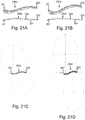
- the superior plates 200a-200c are offered in multiple contours, with exemplary contours illustrated in Figs. 21A-21F .
- Each plate 200a-200c' has an "S" curvature in the A/P direction and a slight bow in the caudal/cranial direction. Plates 200a-200c' following contours with less ( Fig.
- the plates 200a-200c' may have various angles and radiuses or elliptical dimensions, however, the configurations are not limited to the illustrative examples. Selecting a contoured plate 200a-200c' closely matching the bone's contour minimizes plate prominence and irritation under soft tissue.
- the plates 200a-200d may have varying lengths with varying hole configurations.
- Figs. 22 and 23 show superior lateral plates 200a, 200c having a length longer than the length of the superior midshaft plate 200d illustrated in Figs. 24A-24C .
- Each of the plates 200a-200d generally include alternating DCP slots 130 and polyaxial holes 136, however, other hole configurations may be utilized.
- the superior fixation plates 200a and 200b include an additional hole, namely, a sliding slot 240.
- the sliding slot 240 has a rectangular configuration and is configured to receive a sliding slot screw 241 with a wide head 242.
- the shaft of the screw 241 has a diameter smaller than the width of the slot 240 while the head 242 has a diameter greater than the width of the slot 240.
- the slot 240 allows fine bi-directional adjustments of the plate 200 while maintaining provisional placement.
- the screw 241 may also be utilized for permanent fixation.
- the sliding slot screw and all other screws in the set may also be utilized as a stand-alone fragment capture/lag screw.
- the lateral superior fixation plates 200a, 200b include a lateral extension 210.
- a lateral extension 210 Such a plate 200a, 200b may be used, for example, to fix fractures occurring at the far lateral end of the clavicle 10.
- the lateral extension 210 contains a plurality of polyaxial holes 136 that allow many diverging screw trajectories to secure the plate in this thin, metaphyseal bone region, as shown in Figs. 26A-B .
- the polyaxial holes 136 accept locking and non-locking screws.
- nominal, diverging and converging trajectories are intended to secure in regions of dense bone and away from the acromioclavicular joint space.
- the lateral extension 210 also defines a plurality of oblong suture holes 120 similar to those in the shaft of the plate 200a, 200b.
- the lateral extension suture holes 120 have undercuts 122' to allow free passage of suture underneath the plate 200, however, the width of these undercuts 122' is limited to the width of the suture hole 120.
- FIG. 29-34B superior hook plates 200e, 200f will be described.
- the body 202 of the superior hook plates 200e, 200f is similar to the previous embodiments except that a hook member 250 extends from the end 201' of the plate 200e, 200f.
- Such hook plates 200e, 200f may, for example, be utilized to aid healing of acromioclavicular (AC) joint separations with clavicular displacement.
- the hook member 250 includes an extension portion 251 which extends from the end 201' of the plate 200e, 200f to the postero-lateral side of the AC joint 12.
- a descending arm 252 extends inferiorly from the extension portion 251 to a given depth from which a lateral arm 254 angles laterally to hook underneath the acromion 14. This constrains superior displacement of the clavicle 10.
- the hook plates are offered with various descending arm 252 lengths to accommodate diverse shoulder and injury anatomies.
- the lateral arm 254 fans out into a widened head 256, 256' that increases contact surface area between the hook member 250 and the underside of the acromion 14.
- the widened head 256, 256' may have various shapes, with Figs. 34A and 34B illustrating exemplary shapes.
- the widened head 256 in Fig. 34A has a curved spatula shape while the widened head 256' in Fig. 34B has a curved spoon shape, each with smoothed edges.
- the widened heads 256, 256' help to reduce painful irritation, bony erosion, and incidental fracture on the underside of the acromion 14 by distributing the load to a wider area.
- the smoothed edges of the widened head 256, 256' also facilitate insertion into this soft tissue space and eventual removal, and while in place minimizes irritation to the rotator cuff and other soft tissues.
- the straight fixation plates 300 is similar to the anterior and superior fixation plates described above and includes an elongate body 302 extending between opposed ends 301, 303 with an outer surface 305 and an inner, bone contacting surface 307.
- the straight fixation plates 300 differs from the previously described plates in that the straight fixation plate 300 is not pre-bent, but instead may be configured to be bent to an appropriate curved configuration complementing the curvature of the bone to which it will be attached.
- the straight fixation plate 300 may include any of the features described with respect to the anterior and superior plates, including a wider and/or thicker central portion 304, rounded outer and inner surfaces 305, 307, undercuts 112, 114 on the inner surface 307, side relief cuts 116, oblong suture holes 120, undercuts 122, round K-wire holes 126, DCP slots 130 and polyaxial holes 136.
- the straight fixation plate 300 may have varying lengths with varying hole configurations.
- the plate 300 generally includes alternating DCP slots 130 and polyaxial holes 136, with the illustrated embodiments having an additional DCP slot 130 in the central region. However, other hole configurations may be utilized.
- each combined hole 325 includes a relief cut 316 and undercut 322 into the body 302 in alignment with the oblong suture hole 320.
- the relief cut portions 316 are positioned between screw holes thereby reducing the moment of inertia between the screw holes to allow preferential bending between holes, helping to minimize deformation of the screw holes.
- the illustrated relief cuts 316 have a rounded or smooth configuration to minimize the risk of kinking or fracture.
- the undercuts 322 also help reduce the moment of inertia between screw holes to allow preferential bending between holes, helping to minimize deformation of screw holes.
- the combined holes 325 provide further assistance with bending. More specifically, during surgeon contouring of the plate 300b by bending in the caudal/cranial direction, as illustrated in Fig. 40 , the side relief cut 316 of the combined hole 325 on the compression side (bottom side in Fig. 40 ) will deform, or further "crimp", inwards.
- the outer edge of the suture hole 320 on the tension side (upper side of Fig. 40 ) contains more material than is necessary for this span. This tension side will "uncrimp” or deform by necking outwards, resulting in a straighter outer plate edge. Bending to evident failure of the necked material on the tension side may be calibrated to serve as an indicator of excessive bending of the plate 300, making it unusable.
- the intentional regions of deformation during bending created by the combined holes 325 may diminish bending at undesirable regions at the screw holes.
- an intramedullary clavicle nail 400 in accordance with an embodiment of the disclosure will be described.
- a plurality of different sized nails 400 for example, having diameters of 3.0, 3.5, 4.0, 4.5, and 5.0 mm, may be provided as a set.
- the nails 400 enable minimally invasive treatment of select clavicle fractures. Advantages of this technique are much less incision and scarring, and often elimination of soft tissue prominence.
- Each nail 400 includes an elongated body 402 extending from a trailing end 401 to a medial, leading end 403.
- the nail body 402 has a pre-contoured configuration with anatomically appropriate radius R M at the medial, leading end 403.
- the body 402 transitions to a straight region at the trailing end 401.
- the trailing end 401 of the nail 400 exits the posterolateral side of the clavicle 10. The nail 400 is then cut to length and tamped below the bone surface.
- the leading end 403 of the nail 400 has a pointed shape with flats 405 on each side of a rounded tip 407.
- the rounded tip 407 extends to a wide underside 409.
- the pointed shape helps to advance the nail 400 in the medullary canal with minimal pre-drilling, while the wide underside 409 of the tip offers some width to rest against the canal wall. Such resistance helps to provide some rotational stability to maintain the orientation of the pre-curved nail with the restored anterior bone curvature.
- the orthopedic bone plates, intramedullary nails, and systems may be particularly useful in in the treatment of the clavicle.
- the devices may be provided with anatomic shapes suitable for fixation at distinct regions of the clavicle. It is envisioned, however, that the features of one embodiment may be combined with features of another embodiment and the disclosure and associated technology can encompass other embodiments not expressly shown or described herein. It will also be appreciated that although generally described with reference to the clavicle, it will be appreciated that the systems and devices may be adapted for use with any long bone, short bone, flat bone, or the like.
- the invention could be inter alia defined by the following aspects;
Landscapes
- Health & Medical Sciences (AREA)
- Orthopedic Medicine & Surgery (AREA)
- Surgery (AREA)
- Life Sciences & Earth Sciences (AREA)
- Heart & Thoracic Surgery (AREA)
- Nuclear Medicine, Radiotherapy & Molecular Imaging (AREA)
- Engineering & Computer Science (AREA)
- Biomedical Technology (AREA)
- Neurology (AREA)
- Medical Informatics (AREA)
- Molecular Biology (AREA)
- Animal Behavior & Ethology (AREA)
- General Health & Medical Sciences (AREA)
- Public Health (AREA)
- Veterinary Medicine (AREA)
- Surgical Instruments (AREA)
Abstract
Description
- This application is a continuation-in-part of
U.S. application No. 15/719,633, filed September 29, 2017 U.S. provisional application No. 62/469,813, filed March 10, 2017 - The present disclosure is generally directed to surgical devices and methods. More particularly, the present disclosure is directed to trauma plates, fasteners, intramedullary nails, systems, and methods designed to fix fractures, non-unions, and ligamentous injuries of the clavicle or the like.
- The clavicle or collar bone is one of the most commonly broken bones in the body. While some clavicle fractures heal with nonoperative management, more recent studies have found that in cases of specific fracture patterns and locations, not all clavicle fractures behave the same way.
- The focus of treatment of middle third fractures remains nonoperative, although evidence is mounting in support of operative treatment for displaced midshaft clavicle fractures. The incidence of nonunion of displaced distal third fractures is high, and current recommendations are to fix these injuries surgically.
- Patients with the following injuries, for example, are often considered for operative intervention: complete fracture displacement, severe displacement causing tenting of the skin with the risk of puncture, fractures with significant shortening, comminuted fractures with a displaced transverse zed fragment, fractures with neurovascular compromise, displaced medial clavicular fractures with mediastinal structures at risk, polytrauma with multiple fractures, open fractures, fractures where the patient has an inability to tolerate closed treatment, fractures with interposed muscle, established symptomatic nonunion, or concomitant glenoid neck fracture.
- Additionally, evidence is mounting in support of operative treatment for displaced midshaft clavicle fractures, finding that operative repair for these injuries provided better results than did nonoperative treatment. In several studies, outcomes with regard to the rate of successful bone union, functional outcome, time required for patients to resume their daily activities, and overall patient satisfaction were superior in the operative group than in nonoperative patients. There was also significantly less posttraumatic clavicular shortening in the surgical group.
- With an increased consideration of operative repair, improved clavicle fixation systems are desired.
- Clavicle bone plates, intramedullary clavicle nails, systems, and methods of treatment are provided. The systems and devices may be particularly suitable for fixation of the clavicle. Although generally described with reference to the clavicle, it will be appreciated that the systems and devices may be adapted for use with any long bone, short bone, flat bone, or the like.
- In at least one embodiment, the present disclosure provides clavicle fixation device includes an elongated plate extending between first and second ends and defining a central portion, a first end portion between the central portion and the first end, and a second end portion between the central portion and the second end. The elongated plate defines a plurality of spaced apart screw holes. At least one pair of relief cuts extends into the elongated plate on opposite sides thereof and are axially positioned between a pair of the spaced apart screw holes. At least one pair of suture holes extends into the elongated plate along opposite sides thereof and are axially positioned between a pair of the spaced apart screw holes.
- In at least one embodiment, the present disclosure provides a clavicle fixation device including an elongated plate extending between first and second ends, the elongated plate defining a plurality of spaced apart screw holes. At least one pair of relief cuts extends into the elongated plate on opposite sides thereof, the at least one pair of relief cuts axially positioned between a pair of the spaced apart screw holes and at least one pair of suture holes along opposite sides of the elongated plate, the at least one pair of suture holes axially positioned between a pair of the spaced apart screw holes. At least one pair of relief cuts is axially aligned with a pair of suture holes to define combined holes on opposite sides of the elongated plate.
- In at least one embodiment, the present disclosure provides a method of preparing a clavicle fixation device which comprises an elongated plate extending between first and second ends, the elongated plate defining a plurality of spaced apart screw holes, wherein at least one pair of relief cuts extends into the elongated plate on opposite sides thereof, the at least one pair of relief cuts axially positioned between a pair of the spaced apart screw holes and at least one pair of suture holes along opposite sides of the elongated plate, the at least one pair of suture holes axially positioned between a pair of the spaced apart screw holes; and wherein at least one pair of relief cuts is axially aligned with a pair of suture holes to define combined holes on opposite sides of the elongated plate. The method includes the step of bending the elongated plate in the anterior/posterior direction and/or in the caudal/cranial direction at at least one combined hole pair such that the elongated plate has a contour which complements the contour of a clavicle anterior or superior surface.
- Also provided are methods of treatment and kits including bone plates and/or intramedullary nails of varying shapes and sizes, bone anchors, fasteners, insertion tools, and other components for installing the same.
- According to a further aspect of the invention it is provided a clavicle fixation device comprising: an elongated plate extending between first and second ends, the elongated plate defining a plurality of spaced apart screw holes, wherein at least one pair of relief cuts extends into the elongated plate on opposite sides thereof, the at least one pair of relief cuts axially positioned between a pair of the spaced apart screw holes and at least one pair of suture holes along opposite sides of the elongated plate, the at least one pair of suture holes axially positioned between a pair of the spaced apart screw holes; and wherein at least one pair of relief cuts is axially aligned with a pair of suture holes to define combined holes on opposite sides of the elongated plate.
- In a version, an undercut in an inner surface of the elongated plate is aligned with each suture hole and forms a portion of the combined hole.
- In another version the elongated plate has an initial unbent flat contour.
- In a further version a portion of the elongated plate between a relief cut and a suture hole of a combined hole is configured to stretch and straighten when a sufficient tension force is applied to the elongated body proximate the combined hole.
- It is further provided a method of preparing a clavicle fixation device which comprises an elongated plate extending between first and second ends, the elongated plate defining a plurality of spaced apart screw holes, wherein at least one pair of relief cuts extends into the elongated plate on opposite sides thereof, the at least one pair of relief cuts axially positioned between a pair of the spaced apart screw holes and at least one pair of suture holes along opposite sides of the elongated plate, the at least one pair of suture holes axially positioned between a pair of the spaced apart screw holes; and wherein at least one pair of relief cuts is axially aligned with a pair of suture holes to define combined holes on opposite sides of the elongated plate, the method comprising the steps of: bending the elongated plate in the anterior/posterior direction and/or in the caudal/cranial direction at at least one combined hole pair such that the elongated plate has a contour which complements the contour of a clavicle anterior or superior surface.
- The accompanying drawings, which are included to provide a further understanding of the present disclosure, are incorporated in and constitute a part of this specification, illustrate aspects of the present disclosure and together with the detailed description serve to explain the principles of the present disclosure. No attempt is made to show structural details of the present disclosure in more detail than may be necessary for a fundamental understanding of the present disclosure and the various ways in which it may be practiced. In the drawings:
-
Figs. 1A and 1B are perspective views of anterior fixation plates in accordance with embodiments of the present disclosure, each shown positioned along a clavicle; -
Figs. 2A-2D are side elevation views of anterior fixation plates in accordance with embodiments of the disclosure illustrating different contours; -
Figs. 3A and 3B are top plan views of the anterior fixation plates ofFigs. 1A and 1B , respectively; -
Figs. 4A and 4B are front elevation views of the anterior fixation plates ofFigs. 1A and 1B , respectively; -
Figs. 5A and 5B are plan views of end portions of anterior fixation plates in accordance with embodiments of the disclosure; -
Fig. 6 is a perspective view of an end tip of an anterior fixation plate in accordance with an embodiment of the disclosure; -
Fig. 7 is a perspective view of an anterior fixation plate in accordance with an embodiment of the disclosure illustrating the rounded top and undersides thereof; -
Fig. 8 is a perspective view of the underside of a central portion of an anterior fixation plate in accordance with an embodiment of the disclosure; -
Fig. 9 is a perspective view of the underside of an end portion of the anterior fixation plate ofFig. 8 ; -
Fig. 10 is a top perspective view illustrating the cross-sectional profile of a fixation plate in accordance with an embodiment of the disclosure; -
Fig. 11 is a bottom perspective view illustrating the underside of the cross-sectional profile ofFig. 10 ; -
Fig. 12 is a side perspective view of a portion of an anterior fixation plate in accordance with an embodiment of the disclosure illustrating the side relief cuts thereof; -
Fig. 13 is a plan view illustrating the side relief cuts ofFig. 12 ; -
Figs. 14A and 14B are perspective views of the anterior lateral fixation plates ofFigs. 1A and 1B , respectively; -
Fig. 15A is a perspective view of an anterior midshaft fixation plate in accordance with an embodiment of the disclosure; -
Figs. 15B, 15C and 15D are a top plan view, side elevation view and a perspective view, respectively, of another anterior midshaft fixation plate in accordance with an embodiment of the disclosure; -
Fig. 16 is a plan view of a central portion of an anterior fixation plate in accordance with an embodiment of the disclosure; -
Fig. 17 is a side perspective view of the anterior fixation plate ofFig. 16 ; -
Fig. 18 is a cross-sectional view of a portion of an anterior fixation plate in accordance with an embodiment of the invention illustrating a screw extending through a dynamic compression plating slot thereof; -
Fig. 19 is a cross-sectional view of a portion of an anterior fixation plate in accordance with an embodiment of the invention illustrating screws extending through polyaxial holes thereof; -
Figs. 20A, 20B and 20C are perspective views of superior fixation plates in accordance with embodiments of the present disclosure, each shown positioned along a clavicle; -
Figs. 21A and 21B are top and side elevation views of superior fixation plates in accordance with an embodiments of the disclosure illustrating different contours; -
Figs. 21C, 21D and21E are top views of superior fixation plates in accordance with an embodiments of the disclosure illustrating additional contours; -
Fig. 21F is a side elevation view and perspective view of a superior fixation plate in accordance with an embodiment of the disclosure illustrating different contours; -
Fig. 22 is a perspective of the superior fixation plate ofFig. 20 ; -
Fig. 23 is a perspective view of another superior fixation plate in accordance with an embodiment of the present disclosure; -
Figs. 24A, 24B and 24C are a perspective view, a top view, and a bottom perspective view of another superior fixation plate in accordance with an embodiment of the present disclosure; -
Figs. 25A, 25B ,26A and 26B are top and side perspective views, respectively, of end portions of superior fixation plates in accordance with embodiments of the disclosure illustrating a plurality of screws extending through the polyaxial holes thereof; -
Figs. 27A, 27B ,28A and 28B are top and bottom perspective views of a portion of the end of superior fixation plates in accordance with embodiments of the disclosure illustrating the k-wire/suture holes thereof; -
Figs. 29 and 30 are front perspective views of a hook plate in accordance with an embodiment of the disclosure positioned relative a clavicle and AC joint, withFig. 30 illustrating the clavicle and AC joint transparently; -
Figs. 31A and32A are top perspective views of the hook plate ofFig. 29 , withFig. 32A illustrating the clavicle and AC joint transparently,Figs. 31B and 32B are top perspective views similar toFigs. 31A and32A illustrating a hook plate in accordance with another embodiment of the disclosure; -
Figs. 33A, 33B and 33C are a perspective view, top view and side elevation view of the hook plate ofFigs. 31B and 32B ; -
Fig. 34A and 34B are perspective views of the hook portions of the hook plates in accordance with embodiments of the disclosure; -
Fig. 35 is a perspective view of a straight fixation plate in accordance with an embodiment of the invention; -
Fig. 36 is a top view of the straight fixation plate ofFig. 35 ; -
Fig. 37 is a side elevation view of the straight fixation plate ofFig. 35 ; -
Fig. 38 is a bottom perspective view of a portion of the straight fixation plate ofFig. 35 ; -
Fig. 39 is an expanded top view of the straight fixation plate ofFig. 35 ; -
Figs. 40A, 40B ,40C, 40D and 40E illustrated the position of clavicle common fracture zones and the positioning of a plate in accordance with the embodiment of the disclosure relative thereto. -
Fig. 41 is a side elevation view of an intramedullary clavicle nail in accordance with an embodiment of the invention; -
Fig. 42 is a left side perspective view of the tip portion of the intramedullary clavicle nail ofFig. 41 ; -
Fig. 43 is a right side perspective view of the tip portion of the intramedullary clavicle nail ofFig. 41 ; -
Fig. 44 is a bottom perspective view of the tip portion of the intramedullary clavicle nail ofFig. 41 ; and -
Fig. 45 is a side elevation view of the intramedullary clavicle nail ofFig. 41 positioned within the intramedullary of a clavicle. - The aspects of the present disclosure and the various features and advantageous details thereof are explained more fully with reference to the non-limiting aspects and examples that are described and/or illustrated in the accompanying drawings and detailed in the following description. It should be noted that the features illustrated in the drawings are not necessarily drawn to scale, and features of one aspect may be employed with other aspects as the skilled artisan would recognize, even if not explicitly stated herein. Descriptions of well-known components and processing techniques may be omitted so as to not unnecessarily obscure the aspects of the present disclosure. The examples used herein are intended merely to facilitate an understanding of ways in which the present disclosure may be practiced and to further enable those of skill in the art to practice the aspects of the present disclosure. Accordingly, the examples and aspects herein should not be construed as limiting the scope of the present disclosure, which is defined solely by the appended aspects and applicable law. Moreover, it is noted that like reference numerals represent similar parts throughout the several views of the drawings.
- Orthopedic bone plates, intramedullary nails, systems, and methods of treatment are provided. The bone plates and nails may be useful in repair of the clavicle. Although further described with reference to treatment of the clavicle, it will be appreciated that the system and devices may be adapted for use with any bones, including but not limited to, the femur, tibia, humerus, fibula, ulna, radius, bones of the foot, bones of the hand, or the like.
- Referring to
Figs. 1-19 ,anterior fixation plates 100a-100d in accordance with various embodiments of the disclosure will be described.Figs. 1a,1b ,3a, 3b, 4a and 4b illustrateanterior fixation plates clavicle 10. Eachanterior fixation plate elongate body 102 extending between opposed ends 101, 103 with anouter surface 105 and an inner,bone contacting surface 107. - Referring to
Figs. 2A-2D , theanterior plates anterior plates anterior plates Figs. 2A-2D . Eachplate central portion 104 extending betweenend portions Figs. 2A and 2B , the contour of theplate end portions central portion 104 as well as the curvature R1, R2, R3, R4 of eachend portion plate 100a may range, for example, from about 20-30°, about 20-25°, about 23-25°, or about 24°. The angle β of plate 100' may range, for example, from about 30-40°, about 30-35°, about 33-35°, or about 34°. The radius R1, may range, for example, from about 100-200 mm, about 120-160 mm, or about 140mm. The radius R2 may range, for example, from about 10-100 mm, about 60-100 mm, or about 80 mm. The radius R3 may range, for example, from about 50-150 mm, about 90-130 mm, or about 110mm. The radius R4 may range, for example, from about 10-100 mm, about 30-70 mm, or about 50mm. In the illustrated embodiments, the angle α of plate 100 (for example 24°) is smaller than the angle β of plate 100' (for example 34°) and the radiuses R1, R2 (for example 140mm, 80mm) are larger than the radiuses R3, R4 (for example 110mm, 50mm). With the illustrated configurations, theplate 100a ofFig. 2A is said to have a shallow configuration while theplate 100a' ofFig. 2B is said to have a deep configuration. Referring toFigs. 2C and 2D , theplates ends plates plate 100b or a deep configuration as inplate 100b'. Theplates contoured plate - Referring to
Figs. 3A-6 , theanterior fixation plate plate central portion 104 and then tapers to smaller cross-sectional thickness T2, T3 in eachend portion end portions Figs. 5A, 5B and 6 , theplate additional taper 109 at the plate ends 101, 103, beyond the last hole. Theadditional taper 109 aids sub-muscular insertion of the plate for minimally-invasive procedures. - The
plate central portion 104 and then narrows to smaller widths W2, W3 in eachend portion end portions Fig. 5A , in theplate 100a, theend portion 108 narrows at different rates, with theportion 108a closest to thecentral portion 104 narrowing more steeply than theportion 108b toward theend 103, which has a more gradual narrowing. Referring toFig. 5B , in theplate 100b, theend portion 108 narrows at a constant rate. - The
plate plate Figs. 40A, 40B and40D , image studies may show that acommon fracture zone 12 occurs at a location which is about 42% of the length of thebone 10. Accordingly, theplates 100 are configured such that thecentral portion 104 will overly the area at about 42% of the length of thebone 10 when theplate 100 is attached to thebone 10.Figs. 40C and 40E illustrate instances wherein studies show acommon fracture zone 12 at different positions along thebone 10, namely, at 35% of the bone length and 50% of the bone length, respectively. Accordingly, theplates 100 are configured such that thecentral portion 104 will overly the area at about 35% of the length of thebone plate 100 is attached to thebone 10. The length, thicknesses and width of eachplate portion plate 100 narrows in width and tapers lower in thickness. This narrowing and taper enables theplate 100 to be low-profile, minimizing prominence and irritation under soft tissue. - Referring to
Figs. 7-11 , theplate outer surface 105 and a roundedinner surface 107. Therounded surfaces inner surface 107 may further include cylindrical orelliptical undercuts plate 100. Theundercuts plate clavicle bone 10. This may reduce damage to the periosteum, preserve blood supply, reduce osteonecrosis, and speed fracture consolidation. - Referring to
Figs. 10 and 11 , an exemplary undercut pattern is illustrated. The plateinner surface 107 has a curvature with a radius of RA and defines the bone contacting surface. The radius RA is similar to the radius of the clavicle bone surface. Each of theundercuts plate 100 and has a radius RB, RC, respectively. The radiuses RB, RC may be the same or may be different from one another. The radiuses RB, RC of theundercuts undercuts - Referring to
Figs. 12 and 13 ,side relief cuts 116 extend into thebody 102 of theplate relief cuts 116 are provided in opposed pairs on each side of thebody 102, however, other configurations may be utilized. The relief cuts 116 are positioned between screw holes thereby reducing the moment of inertia between the screw holes to allow preferential bending between holes, helping to minimize deformation of the screw holes. The illustratedrelief cuts 116 have a rounded or smooth configuration to minimize the risk of kinking or fracture. As illustrated inFigs. 1A ,4A and14A, therelief cuts 116 in theplate 100a are present near theend portions plate 100a where contour customization by bending is the most likely to be desired, however, other configurations may be utilized. For example, in theplate 100b, as illustrated inFigs. 1B ,4B and14B , therelief cuts 116 are present in thecentral portion 104 as well as near theend portions plate 100b. - Referring to
Figs. 14A-19 , theplates 100a-100d may be provided with various through holes, including oblong suture holes 120, round K-wire holes 126, dynamic compression plating (DCP)slots 130, andpolyaxial holes 136. The oblong suture holes 120 are positioned along but inward of the side edges of theplate body 102. The round K-wire holes 126 are provided at eachend plate Fig. 14A . The oblong suture holes 120 and the round K-wire holes 126 may be used as K-wire holes to allow provisional fixation of theplate oblong suture hole 120 and extends into theinner surface 107 of theplate 100a-100d. Theundercuts 122 have a width that is wider than the width of the correspondingsuture hole 120. Theundercuts 122 enable free passage of suture underneath theplate undercuts 122 help reduce the moment of inertia between screw holes to allow preferential bending between holes, helping to minimize deformation of screw holes. This is useful for plate contour customization. Theundercuts 122 also serve to further reduce the contact surface of theinner surface 107 of theplate 100a-100d. Theundercuts 122 may be co-located withrelief cuts 116 and suture holes 120. - In the illustrated embodiments, the oblong suture holes 120 have a rounded triangular configuration and are positioned between screw holes 130, 136. With this configuration, the oblong suture holes 120 reduce the moment of inertia between screw holes to allow preferential bending between holes, helping to minimize deformation of screw holes. This is useful for plate contour customization. While the oblong suture holes 120 are illustrated with a rounded triangular configuration, other configurations may be utilized, for example, elliptical, round, oval.
- The oblong suture holes 120 also facilitate passage of suture/needles to serve as anchor points useful for reattachment and repositioning of soft tissue damaged during surgery which may aid post-surgical soft tissue healing. The oblong suture holes 120 also facilitate passage of suture/needles for cerclage techniques which may aid in reduction and fixation of bone fragments, particularly "butterfly" fragments on the inferior side of the bone. In the illustrated embodiment, the opposed suture holes 120 on either side of the
plate 100a-100d allow for cerclage running from one side of the plate, down under the bone, up to the opposing suture hole, and potentially across again to the originating hole for successive loops. These opposingholes 120 also aid cerclage perpendicular to the plate trajectory. This is the optimal angle for applying force to reduce fragments toward the plate. - Referring to
Figs. 16 and 18 , eachDCP slot 130 has an oblong configuration withtapered end walls 132 and a central neutralhead receiving area 134. Contact of ascrew head 133 with thetapered end wall 132 may cause medial-lateral motion of theplate 100a-100d relative to the bone to compress a bone fracture. Standard neutral placement may also be achieved by positioning the screw head in the central neutralhead receiving area 134. Compression or neutral placement is typically achieved using anon-locking screw 131, for example, a 3.5 mm non-locking screw. TheDCP slot 130 also enables off-axis, or oblique, screw trajectories in the plane of the slot using non-locking screws. Cancellous screws enable oblique or neutral screw trajectories through theDCP slot 130, useful for fragment capture or load neutralization across the fracture line. - The polyaxial holes 136 accept locking and non-locking screws, both inserted within a cone of angulation, as illustrated in
Fig. 18 . The polyaxial holes 136 may be configured to accept different sized screws, for example, 3.5mm screws at themidshaft end 101 of theplate 100 and 2.5mm screws at the farlateral end 103 of theplate 100. The nominal trajectory of the far lateral holes assists in aiming screws to good quality bone and away from the acromioclavicular joint space, as illustrated inFig. 19 . - As illustrated in
Figs. 14A-15C , theDCP slots 130 andpolyaxial holes 136 may be arranged in various configurations. In the anteriorlateral plate 100a illustrated inFig. 14A , theDCP slots 130 and thepolyaxial holes 136 alternate in thecentral portion 104 and theend portion 106 while theend portion 108 includes consecutive polyaxial holes 136. The anteriorlateral plate 100b illustrated inFig. 14B is similar to theplate 100a wherein theDCP slots 130 and thepolyaxial holes 136 alternate in thecentral portion 104 and theend portion 106 while theend portion 108 includes consecutivepolyaxial holes 136, however theend portion 108 incudes additionalpolyaxial holes 136 compared to the previous embodiment. In theanterior midshaft plate 100c illustrated inFig. 15A , theDCP slots 130 and thepolyaxial holes 136 alternate over the length of theplate 100c. In theanterior midshaft plate 100d illustrated inFigs. 15B-15D , theDCP slots 130 and thepolyaxial holes 136 generally alternate over the length of theplate 100d with the exception of an additional DCP slot near theend 108. Other configurations other than those illustrated may also be utilized. - Referring to
Figs. 20A-28B ,superior fixation plates 200a-200d in accordance with various embodiments of the disclosure will be described.Figs. 20A-20C illustratesuperior fixation plates respective clavicle 10. Thesuperior fixation plates 200a-200d are similar to the anterior fixation plates described above and each includes anelongate body 202 extending between opposed ends 201, 203 with anouter surface 205 and an inner,bone contacting surface 207. Thesuperior fixation plates 200a-200d may include any of the features described with respect to the anterior plates, including rounded outer andinner surfaces inner surface 207,side relief cuts 116, oblong suture holes 120, undercuts 122, round K-wire holes 126,DCP slots 130 andpolyaxial holes 136. - Referring to
Figs. 21A-21F , thesuperior plates 200a-200c are anatomically contoured to fit along the curved anatomy of the superior clavicle. Thesuperior plates 200a-200c are not interchangeable for left-side and right-side clavicles, but instead are configured for either the left-side or right-side clavicle. As the curvature of the bone varies between individuals, thesuperior plates 200a-200c are offered in multiple contours, with exemplary contours illustrated inFigs. 21A-21F . Eachplate 200a-200c' has an "S" curvature in the A/P direction and a slight bow in the caudal/cranial direction.Plates 200a-200c' following contours with less (Fig. 21A and Fig. 21C ) or more (Fig. 21B or Fig. 21D ) "S" curvature may be referred to as "shallow" or "deep" contoured plates, respectively. As illustrated, theplates 200a-200c' may have various angles and radiuses or elliptical dimensions, however, the configurations are not limited to the illustrative examples. Selecting acontoured plate 200a-200c' closely matching the bone's contour minimizes plate prominence and irritation under soft tissue. - Furthermore, as shown in
Figs. 22-24C , theplates 200a-200d may have varying lengths with varying hole configurations.Figs. 22 and23 showsuperior lateral plates superior midshaft plate 200d illustrated inFigs. 24A-24C . Each of theplates 200a-200d generally include alternatingDCP slots 130 andpolyaxial holes 136, however, other hole configurations may be utilized. Thesuperior fixation plates slot 240. Referring toFigs. 25A-25B , the slidingslot 240 has a rectangular configuration and is configured to receive a slidingslot screw 241 with a wide head 242. The shaft of thescrew 241 has a diameter smaller than the width of theslot 240 while the head 242 has a diameter greater than the width of theslot 240. Theslot 240 allows fine bi-directional adjustments of the plate 200 while maintaining provisional placement. Thescrew 241 may also be utilized for permanent fixation. The sliding slot screw and all other screws in the set may also be utilized as a stand-alone fragment capture/lag screw. - Referring to
Figs. 22 and25A-28B , the lateralsuperior fixation plates lateral extension 210. Such aplate clavicle 10. Thelateral extension 210 contains a plurality ofpolyaxial holes 136 that allow many diverging screw trajectories to secure the plate in this thin, metaphyseal bone region, as shown inFigs. 26A-B . The polyaxial holes 136 accept locking and non-locking screws. For ease of surgical planning, nominal, diverging and converging trajectories are intended to secure in regions of dense bone and away from the acromioclavicular joint space. - The
lateral extension 210 also defines a plurality of oblong suture holes 120 similar to those in the shaft of theplate suture hole 120. - Referring to
Figs. 29-34B ,superior hook plates body 202 of thesuperior hook plates hook member 250 extends from the end 201' of theplate Such hook plates hook member 250 includes anextension portion 251 which extends from the end 201' of theplate arm 252 extends inferiorly from theextension portion 251 to a given depth from which alateral arm 254 angles laterally to hook underneath theacromion 14. This constrains superior displacement of theclavicle 10. The hook plates are offered with various descendingarm 252 lengths to accommodate diverse shoulder and injury anatomies. - In each of the illustrated embodiments, the
lateral arm 254 fans out into awidened head 256, 256' that increases contact surface area between thehook member 250 and the underside of theacromion 14. The widenedhead 256, 256' may have various shapes, withFigs. 34A and 34B illustrating exemplary shapes. The widenedhead 256 inFig. 34A has a curved spatula shape while the widened head 256' inFig. 34B has a curved spoon shape, each with smoothed edges. The widened heads 256, 256' help to reduce painful irritation, bony erosion, and incidental fracture on the underside of the acromion 14 by distributing the load to a wider area. The smoothed edges of the widenedhead 256, 256' also facilitate insertion into this soft tissue space and eventual removal, and while in place minimizes irritation to the rotator cuff and other soft tissues. - Referring to
Figs. 35-39 , astraight fixation plate 300 in accordance with various embodiments of the disclosure will be described. Thestraight fixation plates 300 is similar to the anterior and superior fixation plates described above and includes anelongate body 302 extending between opposed ends 301, 303 with anouter surface 305 and an inner,bone contacting surface 307. Thestraight fixation plates 300 differs from the previously described plates in that thestraight fixation plate 300 is not pre-bent, but instead may be configured to be bent to an appropriate curved configuration complementing the curvature of the bone to which it will be attached. That being said, thestraight fixation plate 300 may include any of the features described with respect to the anterior and superior plates, including a wider and/or thickercentral portion 304, rounded outer andinner surfaces inner surface 307,side relief cuts 116, oblong suture holes 120, undercuts 122, round K-wire holes 126,DCP slots 130 andpolyaxial holes 136. Thestraight fixation plate 300 may have varying lengths with varying hole configurations. Theplate 300 generally includes alternatingDCP slots 130 andpolyaxial holes 136, with the illustrated embodiments having anadditional DCP slot 130 in the central region. However, other hole configurations may be utilized. - The
straight fixation plate 300 does not have alternating relief cuts and suture holes like in the previous embodiments, but instead, the holes provide a combined relief cut and suture hole with undercuts. As seen inFigs. 38 and 39 , each combinedhole 325 includes arelief cut 316 and undercut 322 into thebody 302 in alignment with theoblong suture hole 320. As with the previous embodiments, the relief cutportions 316 are positioned between screw holes thereby reducing the moment of inertia between the screw holes to allow preferential bending between holes, helping to minimize deformation of the screw holes. The illustratedrelief cuts 316 have a rounded or smooth configuration to minimize the risk of kinking or fracture. Similar to the previous embodiments, theundercuts 322 also help reduce the moment of inertia between screw holes to allow preferential bending between holes, helping to minimize deformation of screw holes. - Furthermore, the combined
holes 325 provide further assistance with bending. More specifically, during surgeon contouring of the plate 300b by bending in the caudal/cranial direction, as illustrated inFig. 40 , the side relief cut 316 of the combinedhole 325 on the compression side (bottom side inFig. 40 ) will deform, or further "crimp", inwards. The outer edge of thesuture hole 320 on the tension side (upper side ofFig. 40 ) contains more material than is necessary for this span. This tension side will "uncrimp" or deform by necking outwards, resulting in a straighter outer plate edge. Bending to evident failure of the necked material on the tension side may be calibrated to serve as an indicator of excessive bending of theplate 300, making it unusable. The intentional regions of deformation during bending created by the combinedholes 325 may diminish bending at undesirable regions at the screw holes. - Referring to
Figs. 41-45 , anintramedullary clavicle nail 400 in accordance with an embodiment of the disclosure will be described. A plurality of differentsized nails 400, for example, having diameters of 3.0, 3.5, 4.0, 4.5, and 5.0 mm, may be provided as a set. Thenails 400 enable minimally invasive treatment of select clavicle fractures. Advantages of this technique are much less incision and scarring, and often elimination of soft tissue prominence. - Each
nail 400 includes anelongated body 402 extending from a trailingend 401 to a medial, leadingend 403. Thenail body 402 has a pre-contoured configuration with anatomically appropriate radius RM at the medial, leadingend 403. Thebody 402 transitions to a straight region at the trailingend 401. As shown inFig. 45 , upon insertion, the trailingend 401 of thenail 400 exits the posterolateral side of theclavicle 10. Thenail 400 is then cut to length and tamped below the bone surface. - Referring to
Figs. 42-44 , theleading end 403 of thenail 400 has a pointed shape withflats 405 on each side of arounded tip 407. Therounded tip 407 extends to awide underside 409. The pointed shape helps to advance thenail 400 in the medullary canal with minimal pre-drilling, while thewide underside 409 of the tip offers some width to rest against the canal wall. Such resistance helps to provide some rotational stability to maintain the orientation of the pre-curved nail with the restored anterior bone curvature. - The orthopedic bone plates, intramedullary nails, and systems may be particularly useful in in the treatment of the clavicle. The devices may be provided with anatomic shapes suitable for fixation at distinct regions of the clavicle. It is envisioned, however, that the features of one embodiment may be combined with features of another embodiment and the disclosure and associated technology can encompass other embodiments not expressly shown or described herein. It will also be appreciated that although generally described with reference to the clavicle, it will be appreciated that the systems and devices may be adapted for use with any long bone, short bone, flat bone, or the like.
- While the present disclosure has been described in terms of exemplary aspects, those skilled in the art will recognize that the present disclosure can be practiced with modifications in the spirit and scope of the appended aspects. These examples given above are merely illustrative and are not meant to be an exhaustive list of all possible designs, aspects, applications or modifications of the present disclosure.
- The invention could be inter alia defined by the following aspects;
- 1. A clavicle fixation device comprising: an elongated plate extending between first and second ends and defining a central portion, a first end portion between the central portion and the first end, and a second end portion between the central portion and the second end, the elongated plate defining a plurality of spaced apart screw holes, wherein at least one pair of relief cuts extends into the elongated plate on opposite sides thereof, the at least one pair of relief cuts axially positioned between a pair of the spaced apart screw holes and at least one pair of suture holes along opposite sides of the elongated plate, the at least one pair of suture holes axially positioned between a pair of the spaced apart screw holes.
- 2. The clavicle fixation device according to
aspect 1 wherein an undercut in an inner surface of the elongated plate is aligned with each suture hole. - 3. The clavicle fixation device according to
aspect 2 wherein at least a portion of the undercuts have a width larger than a width of the corresponding suture hole. - 4. The clavicle fixation device according to
aspect 1 wherein at least one pair of relief cuts is axially aligned with a pair of suture holes to define combined holes on opposite sides of the elongated plate. - 5. The clavicle fixation device according to
aspect 1 wherein are a plurality of combined hole pairs are defined along the elongated plate. - 6. The clavicle fixation device according to
aspect 1 wherein the elongated plate has an initial contour which complements the contour of a clavicle anterior or superior surface. - 7. The clavicle fixation device according to
aspect 1 wherein the elongated plate has an initial unbent flat contour. - 8. The clavicle fixation device according to
aspect 1 wherein the second end portion narrows moving from the central portion to the second end. - 9. The clavicle fixation device according to
aspect 1 wherein the first end portion narrows at at least two different angles, with a first subportion closer to the central portion narrowing at a steeper angle than a second subportion closer to the first end. - 10. The clavicle fixation device according to
aspect 1 wherein each of the end portions tapers from a maximum thickness adjacent the central portion to a reduced thickness adjacent the respective end. - 11. The clavicle fixation device according to aspect 4 wherein the central portion is sized such that the central portion overlies a common clavicle fracture zone which is determined based on image research study of clavicle fractures.
- 12. The clavicle fixation device according to
aspect 1 wherein the elongated plate defines an outer surface and an inner surface and at least the inner surface has a rounded configuration. - 13. The clavicle fixation device according to
aspect 12 wherein at least one elongated undercut is defined along the inner surface extending between the first and second ends, the elongated undercut having a radial or elliptical dimension smaller than a radial or elliptical dimension of the inner surface. - 14. The clavicle fixation device according to
aspect 12 wherein at least two elongated undercuts are defined along the inner surface extending between the first and second ends, each elongated undercut having a radial or elliptical dimension smaller than a radial or elliptical dimension of the inner surface. - 15. The clavicle fixation device according to
aspect 1 wherein the screw holes include polyaxial holes and dynamic compression plating slots. - 16. A clavicle fixation device comprising: an elongated plate extending between first and second ends, the elongated plate defining a plurality of spaced apart screw holes, wherein at least one pair of relief cuts extends into the elongated plate on opposite sides thereof, the at least one pair of relief cuts axially positioned between a pair of the spaced apart screw holes and at least one pair of suture holes along opposite sides of the elongated plate, the at least one pair of suture holes axially positioned between a pair of the spaced apart screw holes; and wherein at least one pair of relief cuts is axially aligned with a pair of suture holes to define combined holes on opposite sides of the elongated plate.
- 17. The clavicle fixation device according to
aspect 1 wherein an undercut in an inner surface of the elongated plate is aligned with each suture hole and forms a portion of the combined hole. - 18. The clavicle fixation device according to aspect 16 wherein the elongated plate has an initial unbent flat contour.
- 19. The clavicle fixation device according to aspect 16 wherein a portion of the elongated plate between a relief cut and a suture hole of a combined hole is configured to stretch and straighten when a sufficient tension force is applied to the elongated body proximate the combined hole.
- 20. A method of preparing a clavicle fixation device which comprises an elongated plate extending between first and second ends, the elongated plate defining a plurality of spaced apart screw holes, wherein at least one pair of relief cuts extends into the elongated plate on opposite sides thereof, the at least one pair of relief cuts axially positioned between a pair of the spaced apart screw holes and at least one pair of suture holes along opposite sides of the elongated plate, the at least one pair of suture holes axially positioned between a pair of the spaced apart screw holes; and wherein at least one pair of relief cuts is axially aligned with a pair of suture holes to define combined holes on opposite sides of the elongated plate, the method comprising the steps of: bending the elongated plate in the anterior/posterior direction and/or in the caudal/cranial direction at at least one combined hole pair such that the elongated plate has a contour which complements the contour of a clavicle anterior or superior surface.
Claims (15)
- A clavicle fixation device comprising:- an elongated plate extending between first and second ends and defining a central portion, a first end portion between the central portion and the first end, and a second end portion between the central portion and the second end, the elongated plate defining a plurality of spaced apart screw holes,- wherein at least one pair of relief cuts extends into the elongated plate on opposite sides thereof, the at least one pair of relief cuts axially positioned between a pair of the spaced apart screw holes and at least one pair of suture holes along opposite sides of the elongated plate, the at least one pair of suture holes axially positioned between a pair of the spaced apart screw holes.
- The clavicle fixation device according to claim 1 wherein an undercut in an inner surface of the elongated plate is aligned with each suture hole.
- The clavicle fixation device according to claim 2 wherein at least a portion of the undercuts have a width larger than a width of the corresponding suture hole.
- The clavicle fixation device according to claim 1 wherein at least one pair of relief cuts is axially aligned with a pair of suture holes to define combined holes on opposite sides of the elongated plate.
- The clavicle fixation device according to claim 1 wherein are a plurality of combined hole pairs are defined along the elongated plate.
- The clavicle fixation device according to claim 1 wherein the elongated plate has an initial contour which complements the contour of a clavicle anterior or superior surface.
- The clavicle fixation device according to claim 1 wherein the elongated plate has an initial unbent flat contour.
- The clavicle fixation device according to claim 1 wherein the second end portion narrows moving from the central portion to the second end.
- The clavicle fixation device according to claim 1 wherein the first end portion narrows at at least two different angles, with a first subportion closer to the central portion narrowing at a steeper angle than a second subportion closer to the first end.
- The clavicle fixation device according to claim 1 wherein each of the end portions tapers from a maximum thickness adjacent the central portion to a reduced thickness adjacent the respective end.
- The clavicle fixation device according to claim 4 wherein the central portion is sized such that the central portion overlies a common clavicle fracture zone which is determined based on image research study of clavicle fractures.
- The clavicle fixation device according to claim 1 wherein the elongated plate defines an outer surface and an inner surface and at least the inner surface has a rounded configuration.
- The clavicle fixation device according to claim 12 wherein at least one elongated undercut is defined along the inner surface extending between the first and second ends, the elongated undercut having a radial or elliptical dimension smaller than a radial or elliptical dimension of the inner surface.
- The clavicle fixation device according to claim 12 wherein at least two elongated undercuts are defined along the inner surface extending between the first and second ends, each elongated undercut having a radial or elliptical dimension smaller than a radial or elliptical dimension of the inner surface.
- The clavicle fixation device according to claim 1 wherein the screw holes include polyaxial holes and dynamic compression plating slots.
Applications Claiming Priority (3)
| Application Number | Priority Date | Filing Date | Title |
|---|---|---|---|
| US201762469813P | 2017-03-10 | 2017-03-10 | |
| US15/719,633 US10881438B2 (en) | 2017-03-10 | 2017-09-29 | Clavicle fixation system |
| US15/808,113 US10631903B2 (en) | 2017-03-10 | 2017-11-09 | Clavicle fixation system |
Publications (2)
| Publication Number | Publication Date |
|---|---|
| EP3372181A1 true EP3372181A1 (en) | 2018-09-12 |
| EP3372181B1 EP3372181B1 (en) | 2022-06-01 |
Family
ID=63446193
Family Applications (1)
| Application Number | Title | Priority Date | Filing Date |
|---|---|---|---|
| EP18160632.8A Active EP3372181B1 (en) | 2017-03-10 | 2018-03-08 | Clavicle fixation system |
Country Status (3)
| Country | Link |
|---|---|
| US (6) | US10881438B2 (en) |
| EP (1) | EP3372181B1 (en) |
| JP (1) | JP7369512B2 (en) |
Cited By (2)
| Publication number | Priority date | Publication date | Assignee | Title |
|---|---|---|---|---|
| WO2023019370A1 (en) * | 2021-08-18 | 2023-02-23 | Bonebridge Ag | Clavicle bone plate |
| US12582453B2 (en) | 2021-03-22 | 2026-03-24 | Acumed Llc | Anterolateral clavicle fracture fixation plate |
Families Citing this family (24)
| Publication number | Priority date | Publication date | Assignee | Title |
|---|---|---|---|---|
| US10548649B2 (en) * | 2015-04-24 | 2020-02-04 | Biomet Manufacturing, Llc | Clavicle implants |
| US10881438B2 (en) * | 2017-03-10 | 2021-01-05 | Globus Medical, Inc. | Clavicle fixation system |
| USD847343S1 (en) | 2017-11-02 | 2019-04-30 | Paragon 28, Inc. | Hook plate |
| US11071570B2 (en) * | 2018-03-02 | 2021-07-27 | Globus Medical, Inc. | Distal tibial plating system |
| CN110141348A (en) * | 2019-06-20 | 2019-08-20 | 中国科学院大学宁波华美医院(宁波市第二医院) | An atlantoaxial fixation plate with a guide hole and its application method |
| US12185995B2 (en) * | 2019-10-09 | 2025-01-07 | Globus Medical, Inc. | Bone stabilization systems |
| CN114513996B (en) * | 2019-10-29 | 2025-11-28 | 史密夫和内修有限公司 | Periprosthetic bone plate system |
| US11207111B2 (en) * | 2019-11-04 | 2021-12-28 | DePuy Synthes Products, Inc. | Clavicle segmental plate system |
| US20210290276A1 (en) * | 2020-03-20 | 2021-09-23 | Alliance Partners Llc | Medical implant systems and methods of use thereof |
| WO2021236495A1 (en) | 2020-05-19 | 2021-11-25 | Smith & Nephew, Inc. | Periprosthetic bone plate |
| US20230255671A1 (en) * | 2020-07-07 | 2023-08-17 | The General Hospital Corporation | 5th metatarsal compression fixation system |
| BE1028532B1 (en) * | 2020-08-05 | 2022-03-07 | Bv Dr Guy Putzeys | PROXIMAL HUMERAL FIXATION SYSTEM |
| CN114376697A (en) * | 2020-10-19 | 2022-04-22 | 江苏国立医疗器械有限公司 | Height-adjustable bone fracture plate |
| EP4231945A1 (en) | 2020-10-21 | 2023-08-30 | Meticuly Company Limited | Bone fixation system for human bone, method of designing and manufacturing thereof |
| US20240099748A1 (en) * | 2020-12-17 | 2024-03-28 | Dgt Medical Limited | A bone fixation device and system and method for using the device |
| KR102623573B1 (en) * | 2021-01-14 | 2024-01-10 | 주식회사 트라디쏠 | Fracture fixation plate |
| RU208207U1 (en) * | 2021-09-04 | 2021-12-08 | Федеральное государственное бюджетное учреждение "Национальный медицинский исследовательский центр травматологии и ортопедии имени Р.Р. Вредена" Министерства здравоохранения Российской Федерации | Revision anterior plate for osteosynthesis for pseudarthrosis of the clavicle |
| EP4510956A1 (en) * | 2022-04-22 | 2025-02-26 | Universiteit Gent | Medical implant for treatment of a scapula fracture |
| BE1030630B1 (en) * | 2022-06-15 | 2024-01-22 | Life Int | Bone fixation system |
| WO2024237771A1 (en) * | 2023-05-18 | 2024-11-21 | 임준열 | Acromioclavicular joint reduction or clavicle reduction and bone tunnel guide using 3d printer and manufacturing method therefor |
| US20250134562A1 (en) * | 2023-10-30 | 2025-05-01 | DePuy Synthes Products, Inc. | Suture hole with funnel on bone plate |
| WO2025248495A1 (en) * | 2024-05-31 | 2025-12-04 | DePuy Synthes Products, Inc. | Long locking attachment washer for nail-plate combo construct |
| USD1099319S1 (en) * | 2024-06-07 | 2025-10-21 | Stryker European Operations Limited | Bone plate |
| DE102024127783A1 (en) * | 2024-09-25 | 2026-03-26 | Karl Leibinger Asset Management Gmbh & Co. Kg | Osteosynthesis plate and osteosynthesis set |
Citations (4)
| Publication number | Priority date | Publication date | Assignee | Title |
|---|---|---|---|---|
| US20120059424A1 (en) * | 2010-03-10 | 2012-03-08 | Advanced Orthopaedic Solutions, Inc. | Clavicle Bone Plate |
| FR3003749A1 (en) * | 2013-04-02 | 2014-10-03 | Fx Solutions | BONE PLATE FOR REPAIRING A FRACTURED CLAVIC |
| US20150209091A1 (en) * | 2014-01-28 | 2015-07-30 | Biomet C.V. | Implant with Suspended Locking Holes |
| US20160310185A1 (en) * | 2015-04-24 | 2016-10-27 | Robert Sixto | Clavicle implants |
Family Cites Families (238)
| Publication number | Priority date | Publication date | Assignee | Title |
|---|---|---|---|---|
| US1105105A (en) | 1912-02-10 | 1914-07-28 | William O'n Sherman | Surgical appliance. |
| US2486303A (en) | 1948-04-29 | 1949-10-25 | Harry Herschel Leiter | Surgical appliance for bone fractures |
| US3716050A (en) | 1971-02-11 | 1973-02-13 | F Johnston | Olecranon plate |
| CH651192A5 (en) | 1980-11-20 | 1985-09-13 | Synthes Ag | OSTEOSYNTHETIC DEVICE AND CORRESPONDING DRILL GAUGE. |
| FR2517536B1 (en) | 1981-12-09 | 1986-12-12 | Zbikowski Juan | FUNCTIONAL FIXING DEVICE FOR OSTEO-SYNTHESIS USING COMPRESSION PLATES |
| CH662936A5 (en) | 1984-05-18 | 1987-11-13 | Technomed Gmk | BONE JOINT PLATE. |
| US4683878A (en) | 1985-04-29 | 1987-08-04 | Kirschner Medical Corporation | Osteosynthetic fixation plate |
| PL147580B1 (en) | 1986-04-14 | 1989-06-30 | Plate for uniting epiphysis and diaphysis of broken bone | |
| US4776330A (en) | 1986-06-23 | 1988-10-11 | Pfizer Hospital Products Group, Inc. | Modular femoral fixation system |
| US4781183A (en) | 1986-08-27 | 1988-11-01 | American Cyanamid Company | Surgical prosthesis |
| DE8706912U1 (en) | 1987-05-14 | 1987-08-27 | Howmedica GmbH, 2314 Schönkirchen | Small bone plate and screws, particularly for the treatment of fractures of the skull and facial skeleton or similar. |
| US5151103A (en) | 1987-11-03 | 1992-09-29 | Synthes (U.S.A.) | Point contact bone compression plate |
| CH673762A5 (en) | 1987-12-02 | 1990-04-12 | Synthes Ag | |
| IT1237496B (en) | 1989-10-26 | 1993-06-08 | Giuseppe Vrespa | SCREW DEVICE FOR ANCHORING BONE PROSTHESES, METHOD FOR THE APPLICATION OF SUCH DEVICE AND RELATED EQUIPMENT |
| US6001099A (en) | 1998-06-08 | 1999-12-14 | Huebner; Randall J. | Bone plate with varying rigidity |
| US5423826A (en) | 1993-02-05 | 1995-06-13 | Danek Medical, Inc. | Anterior cervical plate holder/drill guide and method of use |
| US5364399A (en) | 1993-02-05 | 1994-11-15 | Danek Medical, Inc. | Anterior cervical plating system |
| US5601553A (en) | 1994-10-03 | 1997-02-11 | Synthes (U.S.A.) | Locking plate and bone screw |
| SE505453C2 (en) | 1995-02-14 | 1997-09-01 | Robert J Medoff | Implantable support plate |
| WO1996029948A1 (en) | 1995-03-27 | 1996-10-03 | Synthes Ag, Chur | Bone plate |
| ES2158127T3 (en) | 1995-09-06 | 2001-09-01 | Synthes Ag | OSEA SHEET. |
| US5676667A (en) | 1995-12-08 | 1997-10-14 | Hausman; Michael | Bone fixation apparatus and method |
| DE19549180A1 (en) | 1995-12-30 | 1997-07-03 | Bosch Gmbh Robert | Stator for electrical machine |
| US5785712A (en) | 1996-04-16 | 1998-07-28 | Terray Corporation | Reconstruction bone plate |
| US6096040A (en) | 1996-06-14 | 2000-08-01 | Depuy Ace Medical Company | Upper extremity bone plates |
| CA2179864C (en) | 1996-06-25 | 2002-05-07 | Robert John Runciman | Bone plate template |
| CA2262441C (en) | 1996-08-12 | 2004-12-28 | Synthes Usa, Llc | Bone plate |
| ZA983955B (en) | 1997-05-15 | 2001-08-13 | Sdgi Holdings Inc | Anterior cervical plating system. |
| US5938664A (en) | 1998-03-31 | 1999-08-17 | Zimmer, Inc. | Orthopaedic bone plate |
| US6533786B1 (en) | 1999-10-13 | 2003-03-18 | Sdgi Holdings, Inc. | Anterior cervical plating system |
| DE19858889B4 (en) | 1998-12-19 | 2008-08-07 | Wolter, Dietmar, Prof. Dr.Med. | Fixation system for bones |
| NZ513746A (en) | 1999-03-09 | 2001-09-28 | Synthes Ag | Bone plate |
| ATE286678T1 (en) | 1999-05-03 | 2005-01-15 | Medartis Ag | LOCKABLE BONE PLATE |
| US7094239B1 (en) | 1999-05-05 | 2006-08-22 | Sdgi Holdings, Inc. | Screws of cortical bone and method of manufacture thereof |
| ES2211583T3 (en) | 1999-09-13 | 2004-07-16 | Synthes Ag Chur | OSEA PLATE SYSTEM. |
| US6974461B1 (en) | 1999-09-14 | 2005-12-13 | Dietmar Wolter | Fixation system for bones |
| DE50011716D1 (en) | 2000-01-27 | 2005-12-29 | Synthes Ag | BONE PLATE |
| US7857838B2 (en) | 2003-03-27 | 2010-12-28 | Depuy Products, Inc. | Anatomical distal radius fracture fixation plate |
| US6712820B2 (en) | 2000-02-01 | 2004-03-30 | Hand Innovations, Inc. | Fixation plate system for dorsal wrist fracture fixation |
| US20040153073A1 (en) | 2000-02-01 | 2004-08-05 | Hand Innovations, Inc. | Orthopedic fixation system including plate element with threaded holes having divergent axes |
| US6866665B2 (en) | 2003-03-27 | 2005-03-15 | Hand Innovations, Llc | Bone fracture fixation system with subchondral and articular surface support |
| US6358250B1 (en) | 2000-02-01 | 2002-03-19 | Hand Innovations, Inc. | Volar fixation system |
| US6283969B1 (en) | 2000-03-10 | 2001-09-04 | Wright Medical Technology, Inc. | Bone plating system |
| US6740088B1 (en) | 2000-10-25 | 2004-05-25 | Sdgi Holdings, Inc. | Anterior lumbar plate and method |
| US8518090B2 (en) | 2010-10-05 | 2013-08-27 | Acumed Llc | Fastener with serrated thread for attachment to a bone plate at a selectable angle |
| US7153309B2 (en) | 2002-11-19 | 2006-12-26 | Acumed Llc | Guide system for bone-repair devices |
| US8523919B2 (en) | 2010-09-27 | 2013-09-03 | Acumed Llc | Targeting guide with a radiopaque marker to facilitate positioning a bone plate on bone |
| SI1389963T1 (en) | 2001-05-28 | 2006-10-31 | Synthes Ag | Bone plate for the fixation of fractures of the proximal humerus |
| JP2003210478A (en) | 2002-01-18 | 2003-07-29 | Ai-Medic:Kk | Plate for ulnar proximal crush fracture fixation |
| US7322983B2 (en) | 2002-02-12 | 2008-01-29 | Ebi, L.P. | Self-locking bone screw and implant |
| US7862597B2 (en) | 2002-08-22 | 2011-01-04 | Warsaw Orthopedic, Inc. | System for stabilizing a portion of the spine |
| US7179260B2 (en) | 2003-09-29 | 2007-02-20 | Smith & Nephew, Inc. | Bone plates and bone plate assemblies |
| FR2845588B1 (en) | 2002-10-09 | 2006-12-15 | Biotech Internat | SELF-LOCKING OSTEOSYNTHESIS DEVICE |
| US6955677B2 (en) | 2002-10-15 | 2005-10-18 | The University Of North Carolina At Chapel Hill | Multi-angular fastening apparatus and method for surgical bone screw/plate systems |
| FR2846870B1 (en) | 2002-11-07 | 2005-07-01 | Fixano | OSTEOSYNTHESIS EQUIPMENT FOR THE TREATMENT OF A "LONG" CUBITUS |
| US20040097937A1 (en) * | 2002-11-19 | 2004-05-20 | Sandi Pike | Orthopedic bone plate |
| US20050187551A1 (en) | 2002-12-02 | 2005-08-25 | Orbay Jorge L. | Bone plate system with bone screws fixed by secondary compression |
| EP1610700B1 (en) | 2003-03-26 | 2010-08-04 | Swiss Orthopedic Solutions SA | Locking bone plate |
| US7722653B2 (en) | 2003-03-26 | 2010-05-25 | Greatbatch Medical S.A. | Locking bone plate |
| US7250053B2 (en) * | 2003-03-27 | 2007-07-31 | Depuy Products, Inc. | Low profile distal radius fracture fixation plate |
| US7294130B2 (en) | 2003-03-27 | 2007-11-13 | Depuy Products, Inc. | Distal radius fracture fixation plate having K-wire hole structured to fix a K-wire in one dimension relative to the plate |
| US7635381B2 (en) | 2003-03-27 | 2009-12-22 | Depuy Products, Inc. | Anatomical distal radius fracture fixation plate with fixed-angle K-wire holes defining a three-dimensional surface |
| US7776076B2 (en) | 2004-05-11 | 2010-08-17 | Synthes Usa, Llc | Bone plate |
| US20050131413A1 (en) | 2003-06-20 | 2005-06-16 | O'driscoll Shawn W. | Bone plate with interference fit screw |
| US8105367B2 (en) | 2003-09-29 | 2012-01-31 | Smith & Nephew, Inc. | Bone plate and bone plate assemblies including polyaxial fasteners |
| WO2007014192A2 (en) | 2005-07-25 | 2007-02-01 | Smith & Nephew, Inc. | Systems and methods for using polyaxial plates |
| CA2545019C (en) | 2003-10-30 | 2012-02-28 | Synthes Gmbh | Bone plate |
| US7867260B2 (en) | 2003-11-05 | 2011-01-11 | Koenigsee Implantate Und Instrumente Zur Osteosynthese Gmbh | Plate used to stabilise distal radius fractures |
| CA2546050C (en) | 2003-11-18 | 2012-08-28 | Synthes Gmbh | Osteosynthesis plate set |
| US7637928B2 (en) | 2004-01-26 | 2009-12-29 | Synthes Usa, Llc | Variable angle locked bone fixation system |
| US8574268B2 (en) | 2004-01-26 | 2013-11-05 | DePuy Synthes Product, LLC | Highly-versatile variable-angle bone plate system |
| US7632277B2 (en) | 2004-03-29 | 2009-12-15 | Woll Bioorthopedics Llc | Orthopedic intramedullary fixation system |
| US7137987B2 (en) | 2004-07-02 | 2006-11-21 | Wright Medical Technology, Inc. | Distal radius bone plating system with locking and non-locking screws |
| AU2005282396A1 (en) | 2004-09-07 | 2006-03-16 | Smith & Nephew, Inc. | Minimal thickness bone plate locking mechanism |
| US20060173458A1 (en) | 2004-10-07 | 2006-08-03 | Micah Forstein | Bone fracture fixation system |
| US8043297B2 (en) | 2004-11-03 | 2011-10-25 | Synthes Usa, Llc | Aiming arm for bone plates |
| US8062296B2 (en) | 2005-03-17 | 2011-11-22 | Depuy Products, Inc. | Modular fracture fixation plate system with multiple metaphyseal and diaphyseal plates |
| US8394130B2 (en) | 2005-03-17 | 2013-03-12 | Biomet C.V. | Modular fracture fixation system |
| US7604657B2 (en) | 2005-09-19 | 2009-10-20 | Depuy Products, Inc. | Bone fixation plate with complex suture anchor locations |
| US8172886B2 (en) | 2004-12-14 | 2012-05-08 | Depuy Products, Inc. | Bone plate with pre-assembled drill guide tips |
| US8118846B2 (en) | 2005-01-28 | 2012-02-21 | Orthohelix Surgical Designs, Inc. | Orthopedic plates for use in clavicle repair and methods for their use |
| EP1693013A1 (en) | 2005-02-22 | 2006-08-23 | Kyon | Plate and screws for treatment of bone fractures |
| US20060241607A1 (en) | 2005-03-31 | 2006-10-26 | Mark Myerson | Metatarsal fixation plate |
| CA2512229C (en) * | 2005-07-14 | 2008-11-18 | Terray Corporation | Clavicular bone plate |
| US8382807B2 (en) | 2005-07-25 | 2013-02-26 | Smith & Nephew, Inc. | Systems and methods for using polyaxial plates |
| DE112006002765A5 (en) | 2005-09-01 | 2008-09-04 | Merete Medical Gmbh | Bone plate with at least one screw for angular stable fixation |
| KR101246113B1 (en) | 2005-10-25 | 2013-03-20 | 앤썸 오르소패딕스, 엘엘씨 | Bone fastening assembly and bushing and screw for use therewith |
| ES2298921T3 (en) | 2005-12-23 | 2008-05-16 | Aap Implantate Ag | OSEA PLATE. |
| US8491593B2 (en) | 2006-01-17 | 2013-07-23 | Stryker Trauma Gmbh | Targeting device for orthopedic implants |
| US7473255B2 (en) | 2006-02-08 | 2009-01-06 | Synthes (U.S.A.) | Transbuccal plate holding cannula |
| US8523921B2 (en) | 2006-02-24 | 2013-09-03 | DePuy Synthes Products, LLC | Tibial plateau leveling osteotomy plate |
| US7875062B2 (en) | 2006-03-07 | 2011-01-25 | Warsaw Orthopedic, Inc. | Methods and devices for retaining bone plate anchors |
| US8808334B2 (en) | 2006-03-07 | 2014-08-19 | Orthohelix Surgical Designs, Inc. | Orthopedic plate |
| US9687282B2 (en) | 2006-03-07 | 2017-06-27 | Orthohelix Surgical Designs, Inc. | Orthopedic plate having threaded holes for locking screws or pegs and non-threaded holes for a variable axis locking mechanism |
| US7867261B2 (en) | 2006-03-17 | 2011-01-11 | Depuy Products, Inc. | Bone plate with variable torsional stiffness at fixed angle holes |
| BRPI0601069B1 (en) | 2006-03-17 | 2014-10-14 | Gm Dos Reis Ind E Com Ltda | BONE BOARD |
| US7951178B2 (en) | 2006-04-03 | 2011-05-31 | Acumed Llc | Bone plates with hybrid apertures |
| US8926675B2 (en) | 2006-04-11 | 2015-01-06 | Biomet Manufacturing, Llc | Contoured bone plate |
| US20070270849A1 (en) | 2006-04-21 | 2007-11-22 | Orbay Jorge L | Fixation Plate With Multifunctional Holes |
| EP2037827B1 (en) | 2006-07-07 | 2014-09-17 | Swiss Pro Orthopedic SA | Bone plate with complex, adjacent holes joined by a relief-space |
| US8512385B2 (en) | 2006-07-07 | 2013-08-20 | Swiss Pro Orthopedic Sa | Bone plate with complex, adjacent holes joined by a bend relief zone |
| US8057520B2 (en) | 2006-07-18 | 2011-11-15 | Orthohelix Surgical Designs, Inc. | Calcaneal plate |
| US8267972B1 (en) | 2006-12-01 | 2012-09-18 | Gehlert Rick J | Bone plate |
| US20080234749A1 (en) | 2007-01-26 | 2008-09-25 | Zimmer Technology, Inc. | Bone plate providing threaded locking head screw capture |
| US8870931B2 (en) | 2007-03-21 | 2014-10-28 | The University Of North Carolina At Chapel Hill | Anti-unscrewing and multi-angular fastening apparatuses and methods for surgical bone screw/plate systems |
| JP5499244B2 (en) | 2007-04-27 | 2014-05-21 | ジンテス ゲゼルシャフト ミット ベシュレンクテル ハフツング | Implant device composed of metal and polymer elements |
| EP1987792B1 (en) | 2007-05-03 | 2011-06-22 | Medartis AG | Fixing device, combination of a fixing device with a long element, assembly with such a combination and osteosynthesis set |
| AR061999A1 (en) | 2007-07-18 | 2008-08-10 | Pizzicara Mario Angel | BLOCKED PLATE OF COMBINED HOLES, STABILITY CONTROL AND DOUBLE ANGULATION, FOR UNION OF FRACTURED BONES |
| ATE527949T1 (en) | 2007-11-02 | 2011-10-15 | Depuy Products Inc | FIXATION SYSTEM FOR ELBOW Fracture |
| US8317842B2 (en) | 2007-11-30 | 2012-11-27 | Biomet C.V. | Distal tibia plating system |
| EP2072016B1 (en) | 2007-12-17 | 2012-10-03 | Stryker Leibinger GmbH & Co. KG | Bone plate instrument and method |
| WO2009100310A1 (en) | 2008-02-06 | 2009-08-13 | Raymond Raven Iii | Subcondylar fracture fixation plate system for tubular bones of the hand |
| US8257406B2 (en) | 2008-02-19 | 2012-09-04 | Orthohelix Surgical Designs, Inc. | Orthopedic plate for use on a single ray in the midfoot |
| US8257403B2 (en) | 2008-02-19 | 2012-09-04 | Orthohelix Surgical Designs, Inc. | Orthopedic plate for use in the midfoot |
| US8167918B2 (en) | 2008-02-19 | 2012-05-01 | Orthohelix Surgical Designs, Inc. | Orthopedic plate for use in the MTP joint |
| FR2928259B1 (en) | 2008-03-07 | 2011-04-22 | D L P Sarl | MATERIAL FOR THE REDUCTION OF A FRACTURE, ESPECIALLY A DISTAL RADIUS FRACTURE |
| WO2009114389A2 (en) | 2008-03-10 | 2009-09-17 | Eduardo Gonzalez-Hernandez | Bone fixation system |
| US8728126B2 (en) | 2008-03-10 | 2014-05-20 | Dennis L. Steffen | Bone fixation system and method |
| US20090248084A1 (en) | 2008-03-27 | 2009-10-01 | Beat Hintermann | Systems and methods for performing ankle arthrodesis in a human patient |
| WO2009121144A1 (en) | 2008-04-03 | 2009-10-08 | Austofix Group Limited | Tool jig for bone implant assembly |
| US8177822B2 (en) | 2008-05-05 | 2012-05-15 | Lars G. Tellman | Contoured bone plate for fracture fixation having hook members and drill guide for same |
| US9283010B2 (en) | 2008-05-05 | 2016-03-15 | Trimed, Incorporated | Contoured bone plate for fracture fixation having hook members and holder/impactor for same |
| WO2009148762A2 (en) | 2008-05-09 | 2009-12-10 | Skeletal Dynamics Llc | Formable bone plate, clamping apparatus, osteotomy system and method for reconstructing a bone |
| US8343155B2 (en) | 2008-05-15 | 2013-01-01 | Zimmer, Inc. | Cable button |
| SE533632C2 (en) | 2008-07-01 | 2010-11-09 | Swemac Innovation Ab | Device for internal fixation of the bone fragments in a bone fracture |
| US8282674B2 (en) * | 2008-07-18 | 2012-10-09 | Suspension Orthopaedic Solutions, Inc. | Clavicle fixation |
| US9072555B2 (en) | 2008-07-21 | 2015-07-07 | Arthrex, Inc. | Carbon fiber reinforced peek bone plate with titanium fixation screws |
| US8262707B2 (en) | 2008-07-31 | 2012-09-11 | Biomet C.V. | Periarticular bone plate with biplanar offset head member |
| US8257405B2 (en) | 2008-07-31 | 2012-09-04 | Biomet C.V. | Periarticular bone plate with biplanar offset head member |
| US20100057086A1 (en) | 2008-08-29 | 2010-03-04 | Zimmer, Inc. | Anodized locking plate components |
| ES2533802T3 (en) | 2008-09-02 | 2015-04-14 | Stryker Trauma Sa | Locator device for a bone plate |
| US8906076B2 (en) | 2008-10-17 | 2014-12-09 | Osteomed Llc | Angulated locking plate and screw |
| US8597334B2 (en) | 2008-10-17 | 2013-12-03 | Osteomed Llc | Angulated locking plate/screw interface |
| DE102008043370A1 (en) | 2008-10-31 | 2010-05-06 | Universität Rostock | Fixation device for bones |
| US8403966B2 (en) | 2008-11-24 | 2013-03-26 | Mbd Medical Llc | Clavicle plate and screws |
| US8444679B2 (en) | 2008-11-24 | 2013-05-21 | Mbd Medical Llc | Clavicle plate and screws |
| US8439918B2 (en) | 2008-12-02 | 2013-05-14 | Suspension Orthopaedic Solutions, Inc. | Ulna fixation |
| US8777998B2 (en) | 2009-02-23 | 2014-07-15 | Orthopediatrics Corp. | Pediatric long bone support or fixation plate |
| US8506608B2 (en) | 2009-03-24 | 2013-08-13 | Douglas Cerynik | Orthopedic fixation device with bioresorbable layer |
| US9322562B2 (en) | 2009-04-01 | 2016-04-26 | Mitsubishi Electric Corporation | Air-conditioning apparatus |
| DE102009016394B4 (en) | 2009-04-07 | 2016-02-11 | Merete Medical Gmbh | Device for stable-angle fixation and compression of a fracture site or osteotomy on a bone |
| EP2238936B1 (en) | 2009-04-09 | 2012-05-23 | Arthrex, Inc. | Clavicle nail with locking end cap |
| EP2248479B1 (en) | 2009-05-06 | 2012-09-19 | Greatbatch Ltd. | Bone plate assembly |
| US8808333B2 (en) | 2009-07-06 | 2014-08-19 | Zimmer Gmbh | Periprosthetic bone plates |
| US8834532B2 (en) | 2009-07-07 | 2014-09-16 | Zimmer Gmbh | Plate for the treatment of bone fractures |
| US20110009865A1 (en) * | 2009-07-13 | 2011-01-13 | Orfaly Robert M | Bone fixation using an intramedullary pin |
| US9259255B2 (en) | 2009-07-15 | 2016-02-16 | Orthohelix Surgical Designs, Inc. | Variable axis locking mechanism for use in orthopedic implants |
| US20130123841A1 (en) | 2009-09-30 | 2013-05-16 | Thomas Lyon | Apparatus and Method for a Suture Button |
| EP2501312B1 (en) | 2009-11-16 | 2016-07-20 | The Research Foundation for The State University of New York | Pre-curved intramedullary clavicle nail and method of using same |
| WO2011076205A1 (en) | 2009-12-22 | 2011-06-30 | Merete Medical Gmbh | Bone plate system for osteosynthesis |
| US9486262B2 (en) * | 2010-01-27 | 2016-11-08 | DePuy Synthes Products, Inc. | System and method for minimally invasive clavicle plate application |
| US8764751B2 (en) | 2010-03-04 | 2014-07-01 | Skeletal Dynamics, Llc | Endosteal nail plate for fixing bone segments |
| EP2542170B1 (en) | 2010-03-04 | 2018-05-09 | Synthes GmbH | Osteotomy system |
| US20110218580A1 (en) | 2010-03-08 | 2011-09-08 | Stryker Trauma Sa | Bone fixation system with curved profile threads |
| US9113970B2 (en) | 2010-03-10 | 2015-08-25 | Orthohelix Surgical Designs, Inc. | System for achieving selectable fixation in an orthopedic plate |
| US8603148B2 (en) | 2010-05-07 | 2013-12-10 | Raymond B. Raven, III | System for treating bone fractures |
| ES2427981T3 (en) | 2010-05-25 | 2013-11-05 | Stryker Trauma Sa | Bone fixation implant |
| USD643121S1 (en) | 2010-05-27 | 2011-08-09 | Ebi, Llc | Orthopedic wrist spanning bone plate |
| USD646785S1 (en) | 2010-05-27 | 2011-10-11 | Ebi, Llc | Orthopedic volar bone plate |
| CN105877829B (en) | 2010-06-07 | 2018-06-22 | 卡波菲克斯整形有限公司 | Composite material bone implant |
| DE102010025001B4 (en) | 2010-06-24 | 2016-08-04 | Aap Implantate Ag | Fixation system with bone plate and bone screw |
| WO2012028192A1 (en) | 2010-09-02 | 2012-03-08 | Neosteo | Osteosynthesis device |
| KR101926339B1 (en) | 2010-09-09 | 2019-03-07 | 신세스 게엠바하 | Surgical nail |
| PL2623057T3 (en) | 2010-09-28 | 2024-05-06 | Olympus Terumo Biomaterials Corp. | Bone plate and bone plate system |
| US8523862B2 (en) | 2011-04-04 | 2013-09-03 | Stryker Leibinger Gmbh & Co. Kg | Bone plate aiming block |
| WO2012050572A1 (en) | 2010-10-13 | 2012-04-19 | Stryker Leibinger Gmbh & Co., Kg. | Bone plate aiming block |
| EP3527144B1 (en) | 2010-11-17 | 2023-12-13 | Arthrex Inc | Adjustable suture-button construct for ankle syndesmosis repair |
| CN201987653U (en) | 2010-12-22 | 2011-09-28 | 蔡林 | Clavicular hook steel plate |
| US8551095B2 (en) * | 2011-02-02 | 2013-10-08 | Bionet Manufacturing, LLC | Bone plate having combination locking and compression screw holes |
| EP2680767A1 (en) | 2011-03-04 | 2014-01-08 | Synthes GmbH | Modular hook plate assembly |
| US9427269B2 (en) | 2011-03-14 | 2016-08-30 | Genossis Llc | Locking screws and plates |
| EP2693963B1 (en) | 2011-04-01 | 2015-06-03 | Synthes GmbH | Posterior vertebral plating system |
| US20140330320A1 (en) | 2011-05-17 | 2014-11-06 | Dietmar Wolter | Bone Plate |
| US8728082B2 (en) | 2011-05-26 | 2014-05-20 | Biomet Manufacturing, Llc | Bone plate positioning scaffold |
| RU2013158111A (en) | 2011-06-15 | 2015-07-20 | Смит Энд Нефью, Инк. | IMPLANT WITH A VARIABLE ANGLE OF FIXATION |
| US20130018426A1 (en) | 2011-07-11 | 2013-01-17 | Feng-Te Tsai | Bone Plate Module with Adjustable Fixing Direction and an Adjustment Ring Thereof |
| CN202313691U (en) | 2011-09-01 | 2012-07-11 | 吴荣博 | Proximal ulna hook plate |
| US10098677B2 (en) | 2011-09-06 | 2018-10-16 | Globus Medical, Inc. | Spinal plate |
| WO2013036362A1 (en) | 2011-09-06 | 2013-03-14 | Synthes Usa, Llc | Pancarpal arthrodesis bone plate |
| DE202011106835U1 (en) | 2011-10-14 | 2012-02-06 | Königsee Implantate GmbH | bone plate |
| TWI452992B (en) | 2011-10-17 | 2014-09-21 | Taichung Veterans General Hospital Vacrs | Interlocking plate system |
| US8940029B2 (en) | 2011-10-17 | 2015-01-27 | Biomet Trauma, LLC | Variable locking bone plating system |
| TW201316942A (en) | 2011-10-28 | 2013-05-01 | Plus Biotechnology Co Ltd A | Clavicle bone plate and clavicle bone plate group |
| US8632574B2 (en) | 2011-12-07 | 2014-01-21 | Biomet C.V. | Reduced component bone plating system |
| US20130150902A1 (en) | 2011-12-13 | 2013-06-13 | Neoortho Produtos Ortopedicos | Blocked bone plate and screw provided with a threaded conic or parabolic head and arrangement comprising an implant and respective insertion method of said implant to a bone tissue |
| US9320554B2 (en) * | 2011-12-22 | 2016-04-26 | Stryker European Holdings I, Llc | Wrist fusion plate |
| US9259217B2 (en) | 2012-01-03 | 2016-02-16 | Biomet Manufacturing, Llc | Suture Button |
| US9107718B2 (en) | 2012-01-10 | 2015-08-18 | Biomet Manufacturing, Llc | Bone plate |
| US9050151B2 (en) | 2012-03-06 | 2015-06-09 | Stryker Trauma Sa | Bone plate and aiming block |
| EP2838458B1 (en) | 2012-04-18 | 2018-09-12 | Materialise N.V. | Orthopedic bone fixation systems and methods |
| HK1209010A1 (en) | 2012-05-22 | 2016-03-24 | Austofix Group Limited | Bone fixation device |
| US9387022B2 (en) | 2012-06-27 | 2016-07-12 | DePuy Synthes Products, Inc. | Variable angle bone fixation device |
| US9265542B2 (en) | 2012-06-27 | 2016-02-23 | DePuy Synthes Products, Inc. | Variable angle bone fixation device |
| US9433452B2 (en) | 2012-08-03 | 2016-09-06 | Nextremity Solutions, Llc | Bone fixation device and method |
| FR2994380B1 (en) | 2012-08-13 | 2015-07-17 | Biotech Ortho | COATING PLATE OF BONE FRAGMENTS AND METHODS OF MAKING SUCH PLATE. |
| CN202821574U (en) | 2012-08-27 | 2013-03-27 | 熊鹰 | Full-locking type inner fixing device and locating-guiding device for broken shoulder |
| CN202821575U (en) | 2012-09-04 | 2013-03-27 | 黄淑明 | Ulna far-end dissection locking type bone plate |
| US20140066998A1 (en) | 2012-09-06 | 2014-03-06 | Jean-Jacques Martin | Assembly comprising an implantable part designed to be fastened to one or more bones or bone portions to be joined, and at least one screw for fastening the implantable part to said bone(s) |
| JP2016506774A (en) | 2013-01-11 | 2016-03-07 | ザ ユーエイビー リサーチ ファンデーション | Device for fixing proximal humeral fractures |
| US9107711B2 (en) | 2013-02-20 | 2015-08-18 | Stryker Trauma Sa | Screw thread with flattened peaks |
| US20160022336A1 (en) | 2013-03-08 | 2016-01-28 | Edward Richard Bateman | Apparatus for Humeral Fracture Repair |
| US20140277178A1 (en) | 2013-03-13 | 2014-09-18 | Wright Medical Technology, Inc. | Posterior Ankle Fusion Plate |
| US20140277181A1 (en) | 2013-03-14 | 2014-09-18 | Arthrex, Inc. | Variable angle locking screw and plate |
| US9700360B2 (en) * | 2013-06-13 | 2017-07-11 | James Platt | Channeled bone plate and methods for implanting the same |
| US9510880B2 (en) | 2013-08-13 | 2016-12-06 | Zimmer, Inc. | Polyaxial locking mechanism |
| US9468479B2 (en) * | 2013-09-06 | 2016-10-18 | Cardinal Health 247, Inc. | Bone plate |
| CN203506858U (en) | 2013-10-30 | 2014-04-02 | 丽水市中心医院 | Internal fixing plate used for distal ulna fracture |
| AU2014259507B2 (en) | 2013-11-08 | 2019-05-30 | Trimed Inc. | Drill guides and inserters for bone plates having hook members |
| ITPI20130095A1 (en) | 2013-11-11 | 2015-05-12 | Umberto Ragghianti | PLAQUE FOR OSTEOSYNTHESIS OF THE DISTAL PERONE / LATERAL MALLEOLUS AND RELATIVE METHOD. |
| US9855083B2 (en) | 2013-12-12 | 2018-01-02 | Extremity Designs, Llc | Bone plate with elevated suture hole structures |
| US20160166297A1 (en) | 2013-12-12 | 2016-06-16 | Extremity Designs, Llc | Bone plate with elevated suture hole structures |
| WO2015105979A1 (en) | 2014-01-08 | 2015-07-16 | Smith & Nephew, Inc. | Drill guide system |
| US9545277B2 (en) | 2014-03-11 | 2017-01-17 | DePuy Synthes Products, Inc. | Bone plate |
| US10226287B2 (en) | 2014-03-31 | 2019-03-12 | Association For The Advancement Of Musculoskeletal | Bone plate with versatile screw holes |
| WO2015164355A1 (en) | 2014-04-21 | 2015-10-29 | The General Hospital Corporation | Fracture fixation device having clip for stabilizing intramedullary nail |
| CN203815563U (en) | 2014-04-29 | 2014-09-10 | 爱派司生技股份有限公司 | Clavicle fixator with anti-oxidation layer on the surface |
| US20160045238A1 (en) | 2014-08-13 | 2016-02-18 | Biomet C.V. | Calcaneal bone plate targeting guide |
| GB2532721B (en) | 2014-11-21 | 2021-02-10 | Everost Uk Ltd | Bone fixation plate |
| US10226289B2 (en) | 2015-01-09 | 2019-03-12 | Biomet Manufacturing, Llc | Anatomic distal fibula plate with anterolateral directed syndesmosis screw holes |
| CN105982727A (en) | 2015-02-11 | 2016-10-05 | 张长青 | Clavicle hooking plate |
| US10238438B2 (en) | 2015-04-22 | 2019-03-26 | Flower Orthopedics Corporation | Proximal humeral fracture plate |
| FR3040132B1 (en) | 2015-08-19 | 2021-11-12 | In2Bones | BOOT TO ASSIST THE POSITIONING AND FIXATION OF A SURGICAL IMPLANT |
| US10966765B2 (en) | 2015-09-05 | 2021-04-06 | Life Spine, Inc. | Orthopedic implants with variable angle bone screw locking |
| AU2016382956A1 (en) * | 2015-12-28 | 2018-08-09 | Glenhurst Labs, Llc | Surgical devices for small bone fracture surgery |
| US10357293B2 (en) | 2016-02-02 | 2019-07-23 | Stryker European Holdings I, Llc | Bone plate with alternating chamfers |
| US11432857B2 (en) * | 2016-08-17 | 2022-09-06 | Globus Medical, Inc. | Stabilization systems |
| US11331128B2 (en) * | 2016-08-17 | 2022-05-17 | Globus Medical Inc. | Distal radius stabilization system |
| US10575884B2 (en) * | 2016-08-17 | 2020-03-03 | Globus Medical, Inc. | Fracture plates, systems, and methods |
| US10751098B2 (en) * | 2016-08-17 | 2020-08-25 | Globus Medical Inc. | Stabilization systems |
| US11213327B2 (en) * | 2016-08-17 | 2022-01-04 | Globus Medical, Inc. | Fracture plates, systems, and methods |
| US11197701B2 (en) * | 2016-08-17 | 2021-12-14 | Globus Medical, Inc. | Stabilization systems |
| US10687873B2 (en) * | 2016-08-17 | 2020-06-23 | Globus Medical Inc. | Stabilization systems |
| US11141204B2 (en) * | 2016-08-17 | 2021-10-12 | Globus Medical Inc. | Wrist stabilization systems |
| US10881438B2 (en) * | 2017-03-10 | 2021-01-05 | Globus Medical, Inc. | Clavicle fixation system |
| US10905477B2 (en) * | 2017-03-13 | 2021-02-02 | Globus Medical, Inc. | Bone stabilization systems |
| US10687854B2 (en) * | 2017-05-30 | 2020-06-23 | DePuy Synthes Products, Inc. | Acromioclavicular hook plate |
| US11224468B2 (en) * | 2018-03-02 | 2022-01-18 | Globus Medical, Inc. | Distal tibial plating system |
| US11071570B2 (en) * | 2018-03-02 | 2021-07-27 | Globus Medical, Inc. | Distal tibial plating system |
-
2017
- 2017-09-29 US US15/719,633 patent/US10881438B2/en active Active
- 2017-11-09 US US15/808,113 patent/US10631903B2/en active Active
-
2018
- 2018-03-08 EP EP18160632.8A patent/EP3372181B1/en active Active
- 2018-03-09 JP JP2018042740A patent/JP7369512B2/en active Active
-
2020
- 2020-03-24 US US16/827,763 patent/US11357554B2/en active Active
-
2022
- 2022-05-18 US US17/747,069 patent/US11857229B2/en active Active
-
2023
- 2023-12-21 US US18/392,734 patent/US12161372B2/en active Active
-
2024
- 2024-11-21 US US18/954,854 patent/US20250082379A1/en active Pending
Patent Citations (4)
| Publication number | Priority date | Publication date | Assignee | Title |
|---|---|---|---|---|
| US20120059424A1 (en) * | 2010-03-10 | 2012-03-08 | Advanced Orthopaedic Solutions, Inc. | Clavicle Bone Plate |
| FR3003749A1 (en) * | 2013-04-02 | 2014-10-03 | Fx Solutions | BONE PLATE FOR REPAIRING A FRACTURED CLAVIC |
| US20150209091A1 (en) * | 2014-01-28 | 2015-07-30 | Biomet C.V. | Implant with Suspended Locking Holes |
| US20160310185A1 (en) * | 2015-04-24 | 2016-10-27 | Robert Sixto | Clavicle implants |
Cited By (2)
| Publication number | Priority date | Publication date | Assignee | Title |
|---|---|---|---|---|
| US12582453B2 (en) | 2021-03-22 | 2026-03-24 | Acumed Llc | Anterolateral clavicle fracture fixation plate |
| WO2023019370A1 (en) * | 2021-08-18 | 2023-02-23 | Bonebridge Ag | Clavicle bone plate |
Also Published As
| Publication number | Publication date |
|---|---|
| JP2018171433A (en) | 2018-11-08 |
| US12161372B2 (en) | 2024-12-10 |
| US10881438B2 (en) | 2021-01-05 |
| EP3372181B1 (en) | 2022-06-01 |
| US20180256224A1 (en) | 2018-09-13 |
| US20250082379A1 (en) | 2025-03-13 |
| US11857229B2 (en) | 2024-01-02 |
| JP7369512B2 (en) | 2023-10-26 |
| US20240197373A1 (en) | 2024-06-20 |
| US20220273347A1 (en) | 2022-09-01 |
| US20180256226A1 (en) | 2018-09-13 |
| US20200222093A1 (en) | 2020-07-16 |
| US11357554B2 (en) | 2022-06-14 |
| US10631903B2 (en) | 2020-04-28 |
Similar Documents
| Publication | Publication Date | Title |
|---|---|---|
| US12161372B2 (en) | Clavicle fixation system | |
| AU2019250124B2 (en) | Metacarpal neck plate | |
| US12150683B2 (en) | Clavicle implants | |
| US12042194B2 (en) | Bone stabilization systems | |
| US8652179B2 (en) | Bone plate extender and extension system for bone restoration and methods of use thereof | |
| US20120209333A1 (en) | Fracture fixation plate | |
| US11992251B2 (en) | Clavicle segmental plate system | |
| EP3443918B1 (en) | Femur plate | |
| WO1996022743A1 (en) | Pin plate | |
| EP3542739A1 (en) | Bone stabilization systems | |
| WO2025177040A1 (en) | Antero-medial locking compression plate for distal shaft humerus fracture treatment and its utilization method thereof | |
| Smekal et al. | Intramedullary Nailing of the Clavicle |
Legal Events
| Date | Code | Title | Description |
|---|---|---|---|
| PUAI | Public reference made under article 153(3) epc to a published international application that has entered the european phase |
Free format text: ORIGINAL CODE: 0009012 |
|
| STAA | Information on the status of an ep patent application or granted ep patent |
Free format text: STATUS: THE APPLICATION HAS BEEN PUBLISHED |
|
| AK | Designated contracting states |
Kind code of ref document: A1 Designated state(s): AL AT BE BG CH CY CZ DE DK EE ES FI FR GB GR HR HU IE IS IT LI LT LU LV MC MK MT NL NO PL PT RO RS SE SI SK SM TR |
|
| AX | Request for extension of the european patent |
Extension state: BA ME |
|
| STAA | Information on the status of an ep patent application or granted ep patent |
Free format text: STATUS: REQUEST FOR EXAMINATION WAS MADE |
|
| 17P | Request for examination filed |
Effective date: 20190306 |
|
| RBV | Designated contracting states (corrected) |
Designated state(s): AL AT BE BG CH CY CZ DE DK EE ES FI FR GB GR HR HU IE IS IT LI LT LU LV MC MK MT NL NO PL PT RO RS SE SI SK SM TR |
|
| GRAP | Despatch of communication of intention to grant a patent |
Free format text: ORIGINAL CODE: EPIDOSNIGR1 |
|
| STAA | Information on the status of an ep patent application or granted ep patent |
Free format text: STATUS: GRANT OF PATENT IS INTENDED |
|
| INTG | Intention to grant announced |
Effective date: 20220324 |
|
| GRAA | (expected) grant |
Free format text: ORIGINAL CODE: 0009210 |
|
| GRAS | Grant fee paid |
Free format text: ORIGINAL CODE: EPIDOSNIGR3 |
|
| STAA | Information on the status of an ep patent application or granted ep patent |
Free format text: STATUS: THE PATENT HAS BEEN GRANTED |
|
| AK | Designated contracting states |
Kind code of ref document: B1 Designated state(s): AL AT BE BG CH CY CZ DE DK EE ES FI FR GB GR HR HU IE IS IT LI LT LU LV MC MK MT NL NO PL PT RO RS SE SI SK SM TR |
|
| REG | Reference to a national code |
Ref country code: GB Ref legal event code: FG4D |
|
| REG | Reference to a national code |
Ref country code: AT Ref legal event code: REF Ref document number: 1494875 Country of ref document: AT Kind code of ref document: T Effective date: 20220615 Ref country code: CH Ref legal event code: EP Ref country code: DE Ref legal event code: R096 Ref document number: 602018036083 Country of ref document: DE |
|
| REG | Reference to a national code |
Ref country code: IE Ref legal event code: FG4D |
|
| REG | Reference to a national code |
Ref country code: LT Ref legal event code: MG9D |
|
| REG | Reference to a national code |
Ref country code: NL Ref legal event code: MP Effective date: 20220601 |
|
| PG25 | Lapsed in a contracting state [announced via postgrant information from national office to epo] |
Ref country code: SE Free format text: LAPSE BECAUSE OF FAILURE TO SUBMIT A TRANSLATION OF THE DESCRIPTION OR TO PAY THE FEE WITHIN THE PRESCRIBED TIME-LIMIT Effective date: 20220601 Ref country code: NO Free format text: LAPSE BECAUSE OF FAILURE TO SUBMIT A TRANSLATION OF THE DESCRIPTION OR TO PAY THE FEE WITHIN THE PRESCRIBED TIME-LIMIT Effective date: 20220901 Ref country code: LT Free format text: LAPSE BECAUSE OF FAILURE TO SUBMIT A TRANSLATION OF THE DESCRIPTION OR TO PAY THE FEE WITHIN THE PRESCRIBED TIME-LIMIT Effective date: 20220601 Ref country code: HR Free format text: LAPSE BECAUSE OF FAILURE TO SUBMIT A TRANSLATION OF THE DESCRIPTION OR TO PAY THE FEE WITHIN THE PRESCRIBED TIME-LIMIT Effective date: 20220601 Ref country code: GR Free format text: LAPSE BECAUSE OF FAILURE TO SUBMIT A TRANSLATION OF THE DESCRIPTION OR TO PAY THE FEE WITHIN THE PRESCRIBED TIME-LIMIT Effective date: 20220902 Ref country code: FI Free format text: LAPSE BECAUSE OF FAILURE TO SUBMIT A TRANSLATION OF THE DESCRIPTION OR TO PAY THE FEE WITHIN THE PRESCRIBED TIME-LIMIT Effective date: 20220601 Ref country code: ES Free format text: LAPSE BECAUSE OF FAILURE TO SUBMIT A TRANSLATION OF THE DESCRIPTION OR TO PAY THE FEE WITHIN THE PRESCRIBED TIME-LIMIT Effective date: 20220601 Ref country code: BG Free format text: LAPSE BECAUSE OF FAILURE TO SUBMIT A TRANSLATION OF THE DESCRIPTION OR TO PAY THE FEE WITHIN THE PRESCRIBED TIME-LIMIT Effective date: 20220901 |
|
| REG | Reference to a national code |
Ref country code: AT Ref legal event code: MK05 Ref document number: 1494875 Country of ref document: AT Kind code of ref document: T Effective date: 20220601 |
|
| PG25 | Lapsed in a contracting state [announced via postgrant information from national office to epo] |
Ref country code: RS Free format text: LAPSE BECAUSE OF FAILURE TO SUBMIT A TRANSLATION OF THE DESCRIPTION OR TO PAY THE FEE WITHIN THE PRESCRIBED TIME-LIMIT Effective date: 20220601 Ref country code: PL Free format text: LAPSE BECAUSE OF FAILURE TO SUBMIT A TRANSLATION OF THE DESCRIPTION OR TO PAY THE FEE WITHIN THE PRESCRIBED TIME-LIMIT Effective date: 20220601 Ref country code: LV Free format text: LAPSE BECAUSE OF FAILURE TO SUBMIT A TRANSLATION OF THE DESCRIPTION OR TO PAY THE FEE WITHIN THE PRESCRIBED TIME-LIMIT Effective date: 20220601 |
|
| PG25 | Lapsed in a contracting state [announced via postgrant information from national office to epo] |
Ref country code: NL Free format text: LAPSE BECAUSE OF FAILURE TO SUBMIT A TRANSLATION OF THE DESCRIPTION OR TO PAY THE FEE WITHIN THE PRESCRIBED TIME-LIMIT Effective date: 20220601 |
|
| PG25 | Lapsed in a contracting state [announced via postgrant information from national office to epo] |
Ref country code: SM Free format text: LAPSE BECAUSE OF FAILURE TO SUBMIT A TRANSLATION OF THE DESCRIPTION OR TO PAY THE FEE WITHIN THE PRESCRIBED TIME-LIMIT Effective date: 20220601 Ref country code: SK Free format text: LAPSE BECAUSE OF FAILURE TO SUBMIT A TRANSLATION OF THE DESCRIPTION OR TO PAY THE FEE WITHIN THE PRESCRIBED TIME-LIMIT Effective date: 20220601 Ref country code: RO Free format text: LAPSE BECAUSE OF FAILURE TO SUBMIT A TRANSLATION OF THE DESCRIPTION OR TO PAY THE FEE WITHIN THE PRESCRIBED TIME-LIMIT Effective date: 20220601 Ref country code: PT Free format text: LAPSE BECAUSE OF FAILURE TO SUBMIT A TRANSLATION OF THE DESCRIPTION OR TO PAY THE FEE WITHIN THE PRESCRIBED TIME-LIMIT Effective date: 20221003 Ref country code: EE Free format text: LAPSE BECAUSE OF FAILURE TO SUBMIT A TRANSLATION OF THE DESCRIPTION OR TO PAY THE FEE WITHIN THE PRESCRIBED TIME-LIMIT Effective date: 20220601 Ref country code: CZ Free format text: LAPSE BECAUSE OF FAILURE TO SUBMIT A TRANSLATION OF THE DESCRIPTION OR TO PAY THE FEE WITHIN THE PRESCRIBED TIME-LIMIT Effective date: 20220601 Ref country code: AT Free format text: LAPSE BECAUSE OF FAILURE TO SUBMIT A TRANSLATION OF THE DESCRIPTION OR TO PAY THE FEE WITHIN THE PRESCRIBED TIME-LIMIT Effective date: 20220601 |
|
| PG25 | Lapsed in a contracting state [announced via postgrant information from national office to epo] |
Ref country code: IS Free format text: LAPSE BECAUSE OF FAILURE TO SUBMIT A TRANSLATION OF THE DESCRIPTION OR TO PAY THE FEE WITHIN THE PRESCRIBED TIME-LIMIT Effective date: 20221001 |
|
| REG | Reference to a national code |
Ref country code: DE Ref legal event code: R097 Ref document number: 602018036083 Country of ref document: DE |
|
| PG25 | Lapsed in a contracting state [announced via postgrant information from national office to epo] |
Ref country code: AL Free format text: LAPSE BECAUSE OF FAILURE TO SUBMIT A TRANSLATION OF THE DESCRIPTION OR TO PAY THE FEE WITHIN THE PRESCRIBED TIME-LIMIT Effective date: 20220601 |
|
| PLBE | No opposition filed within time limit |
Free format text: ORIGINAL CODE: 0009261 |
|
| STAA | Information on the status of an ep patent application or granted ep patent |
Free format text: STATUS: NO OPPOSITION FILED WITHIN TIME LIMIT |
|
| PG25 | Lapsed in a contracting state [announced via postgrant information from national office to epo] |
Ref country code: DK Free format text: LAPSE BECAUSE OF FAILURE TO SUBMIT A TRANSLATION OF THE DESCRIPTION OR TO PAY THE FEE WITHIN THE PRESCRIBED TIME-LIMIT Effective date: 20220601 |
|
| 26N | No opposition filed |
Effective date: 20230302 |
|
| PG25 | Lapsed in a contracting state [announced via postgrant information from national office to epo] |
Ref country code: SI Free format text: LAPSE BECAUSE OF FAILURE TO SUBMIT A TRANSLATION OF THE DESCRIPTION OR TO PAY THE FEE WITHIN THE PRESCRIBED TIME-LIMIT Effective date: 20220601 |
|
| PG25 | Lapsed in a contracting state [announced via postgrant information from national office to epo] |
Ref country code: MC Free format text: LAPSE BECAUSE OF FAILURE TO SUBMIT A TRANSLATION OF THE DESCRIPTION OR TO PAY THE FEE WITHIN THE PRESCRIBED TIME-LIMIT Effective date: 20220601 |
|
| REG | Reference to a national code |
Ref country code: CH Ref legal event code: PL |
|
| REG | Reference to a national code |
Ref country code: BE Ref legal event code: MM Effective date: 20230331 |
|
| PG25 | Lapsed in a contracting state [announced via postgrant information from national office to epo] |
Ref country code: LU Free format text: LAPSE BECAUSE OF NON-PAYMENT OF DUE FEES Effective date: 20230308 |
|
| REG | Reference to a national code |
Ref country code: IE Ref legal event code: MM4A |
|
| PG25 | Lapsed in a contracting state [announced via postgrant information from national office to epo] |
Ref country code: LI Free format text: LAPSE BECAUSE OF NON-PAYMENT OF DUE FEES Effective date: 20230331 Ref country code: IT Free format text: LAPSE BECAUSE OF FAILURE TO SUBMIT A TRANSLATION OF THE DESCRIPTION OR TO PAY THE FEE WITHIN THE PRESCRIBED TIME-LIMIT Effective date: 20220601 Ref country code: IE Free format text: LAPSE BECAUSE OF NON-PAYMENT OF DUE FEES Effective date: 20230308 Ref country code: FR Free format text: LAPSE BECAUSE OF NON-PAYMENT OF DUE FEES Effective date: 20230331 Ref country code: CH Free format text: LAPSE BECAUSE OF NON-PAYMENT OF DUE FEES Effective date: 20230331 |
|
| PG25 | Lapsed in a contracting state [announced via postgrant information from national office to epo] |
Ref country code: BE Free format text: LAPSE BECAUSE OF NON-PAYMENT OF DUE FEES Effective date: 20230331 |
|
| PG25 | Lapsed in a contracting state [announced via postgrant information from national office to epo] |
Ref country code: BG Free format text: LAPSE BECAUSE OF FAILURE TO SUBMIT A TRANSLATION OF THE DESCRIPTION OR TO PAY THE FEE WITHIN THE PRESCRIBED TIME-LIMIT Effective date: 20220601 |
|
| PG25 | Lapsed in a contracting state [announced via postgrant information from national office to epo] |
Ref country code: BG Free format text: LAPSE BECAUSE OF FAILURE TO SUBMIT A TRANSLATION OF THE DESCRIPTION OR TO PAY THE FEE WITHIN THE PRESCRIBED TIME-LIMIT Effective date: 20220601 |
|
| PG25 | Lapsed in a contracting state [announced via postgrant information from national office to epo] |
Ref country code: CY Free format text: LAPSE BECAUSE OF FAILURE TO SUBMIT A TRANSLATION OF THE DESCRIPTION OR TO PAY THE FEE WITHIN THE PRESCRIBED TIME-LIMIT; INVALID AB INITIO Effective date: 20180308 |
|
| PG25 | Lapsed in a contracting state [announced via postgrant information from national office to epo] |
Ref country code: HU Free format text: LAPSE BECAUSE OF FAILURE TO SUBMIT A TRANSLATION OF THE DESCRIPTION OR TO PAY THE FEE WITHIN THE PRESCRIBED TIME-LIMIT; INVALID AB INITIO Effective date: 20180308 |
|
| PG25 | Lapsed in a contracting state [announced via postgrant information from national office to epo] |
Ref country code: TR Free format text: LAPSE BECAUSE OF FAILURE TO SUBMIT A TRANSLATION OF THE DESCRIPTION OR TO PAY THE FEE WITHIN THE PRESCRIBED TIME-LIMIT Effective date: 20220601 |
|
| PGFP | Annual fee paid to national office [announced via postgrant information from national office to epo] |
Ref country code: GB Payment date: 20260106 Year of fee payment: 9 |
|
| PGFP | Annual fee paid to national office [announced via postgrant information from national office to epo] |
Ref country code: DE Payment date: 20260102 Year of fee payment: 9 |